EP3189815A1 - Gripping device - Google Patents
Gripping device Download PDFInfo
- Publication number
- EP3189815A1 EP3189815A1 EP16275006.1A EP16275006A EP3189815A1 EP 3189815 A1 EP3189815 A1 EP 3189815A1 EP 16275006 A EP16275006 A EP 16275006A EP 3189815 A1 EP3189815 A1 EP 3189815A1
- Authority
- EP
- European Patent Office
- Prior art keywords
- body portion
- user
- gripping device
- jaws
- elongate member
- Prior art date
- Legal status (The legal status is an assumption and is not a legal conclusion. Google has not performed a legal analysis and makes no representation as to the accuracy of the status listed.)
- Ceased
Links
Images


Classifications
-
- A—HUMAN NECESSITIES
- A61—MEDICAL OR VETERINARY SCIENCE; HYGIENE
- A61F—FILTERS IMPLANTABLE INTO BLOOD VESSELS; PROSTHESES; DEVICES PROVIDING PATENCY TO, OR PREVENTING COLLAPSING OF, TUBULAR STRUCTURES OF THE BODY, e.g. STENTS; ORTHOPAEDIC, NURSING OR CONTRACEPTIVE DEVICES; FOMENTATION; TREATMENT OR PROTECTION OF EYES OR EARS; BANDAGES, DRESSINGS OR ABSORBENT PADS; FIRST-AID KITS
- A61F2/00—Filters implantable into blood vessels; Prostheses, i.e. artificial substitutes or replacements for parts of the body; Appliances for connecting them with the body; Devices providing patency to, or preventing collapsing of, tubular structures of the body, e.g. stents
- A61F2/50—Prostheses not implantable in the body
- A61F2/54—Artificial arms or hands or parts thereof
- A61F2/58—Elbows; Wrists ; Other joints; Hands
- A61F2/583—Hands; Wrist joints
- A61F2/588—Hands having holding devices shaped differently from human fingers, e.g. claws, hooks, tubes
-
- A—HUMAN NECESSITIES
- A61—MEDICAL OR VETERINARY SCIENCE; HYGIENE
- A61F—FILTERS IMPLANTABLE INTO BLOOD VESSELS; PROSTHESES; DEVICES PROVIDING PATENCY TO, OR PREVENTING COLLAPSING OF, TUBULAR STRUCTURES OF THE BODY, e.g. STENTS; ORTHOPAEDIC, NURSING OR CONTRACEPTIVE DEVICES; FOMENTATION; TREATMENT OR PROTECTION OF EYES OR EARS; BANDAGES, DRESSINGS OR ABSORBENT PADS; FIRST-AID KITS
- A61F4/00—Methods or devices enabling patients or disabled persons to operate an apparatus or a device not forming part of the body
-
- B—PERFORMING OPERATIONS; TRANSPORTING
- B25—HAND TOOLS; PORTABLE POWER-DRIVEN TOOLS; MANIPULATORS
- B25J—MANIPULATORS; CHAMBERS PROVIDED WITH MANIPULATION DEVICES
- B25J1/00—Manipulators positioned in space by hand
- B25J1/04—Manipulators positioned in space by hand rigid, e.g. shelf-reachers
Definitions
- the present invention relates to gripping devices.
- Manual gripping or grabbing tools may be used by people in their daily activities to help with reaching and gripping items.
- the present invention provides a gripping device comprising: an elongate first body portion having a first end and a second end opposite to the first end, the first body portion comprising a first arm mount for fitting to a forearm of a user; a jaw portion comprising a pair of jaws moveable relative to each other between a fully open position and a fully clamped position thereof, the jaw portion being coupled to the first end of the first body portion; a second body portion coupled to the second end of the first body portion, and moveable with respect to the first body portion, the second body portion comprising a second arm mount for fitting to an upper arm of a user; and a pull member operatively coupled between the jaw portion and the second body portion, the pull member being at least partially housed within the first body portion.
- Movement of the second body portion with respect to the first body portion is operative to move the pull member thereby to cause the pull member to act on the jaw portion so as to cause the jaws to move from at or proximate to the fully open position thereof towards the fully clamped position thereof.
- the jaw portion may further comprise a ratchet system configured to oppose movement of the jaws from at or proximate to the fully clamped position thereof towards the fully open position thereof.
- the jaw portion may further comprise a release mechanism for releasing the ratchet system so as to allow movement of the jaws from at or proximate to the fully clamped position thereof towards the fully open position thereof.
- the jaw portion may further comprise a first spring mechanism for moving the jaws from at or proximate to the fully clamped position thereof towards the fully open position thereof responsive to the release mechanism releasing the ratchet system.
- the first body portion may be selectively extendible such that a distance between the jaw portion and the second body portion can be varied.
- the first body portion may further comprise a first elongate member and a second elongate member slidably mounted to the first elongate member.
- the jaw portion may be coupled to the second elongate member.
- the second body portion may be coupled to the first elongate member.
- the first body portion may further comprise a handle portion moveable between a first position and a second position thereof. The first position of the handle portion may be such that the handle portion is engaged with the first elongate member and the second elongate member thereby to fix the relative positions of the first elongate member and the second elongate member.
- the second position of the handle portion may be such that the handle portion is not engaged with at least one of the first elongate member and the second elongate member thereby allowing the relative movement of the first elongate member and the second elongate member.
- the first body portion may further comprise a second spring mechanism for moving the handle portion from the second position thereof to the first position thereof.
- the movement of the second body portion with respect to the first body portion that moves the pull member and thereby causes the pull member to act on the jaw portion so as to cause the jaws to move from at or proximate to the fully open position thereof towards the fully clamped position thereof may correspond to the user's arm being straightened.
- Further movement of the second body portion with respect to the first body portion may be operative to move the pull member and thereby causes the pull member to act on the jaw portion so as to cause the jaws to move from at or proximate to the fully clamped position thereof towards the fully open position thereof.
- the further movement may be in an opposite direction to that of the movement of the second body portion with respect to the first body portion that moves the pull member and thereby causes the pull member to act on the jaw portion so as to cause the jaws to move from at or proximate to the fully open position thereof towards the fully clamped position thereof.
- the pull member may be a cable.
- At least part of the pull member may be housed in a sleeve.
- the second body portion may comprise a roller chain system that, when the first arm mount is fitted to the forearm of a user and the second arm mount is fitted the upper arm of that user, is located at an elbow of that user.
- the present invention provides a method of providing a gripping device, the method comprising: providing an elongate first body portion having a first end and a second end opposite to the first end, the first body portion comprising a first arm mount for fitting to a forearm of a user; coupling a jaw portion the first end of the first body portion, the jaw portion comprising a pair of jaws moveable relative to each other between a fully open position and a fully clamped position thereof; coupling a second body portion to the second end of the first body portion such that the second body portion is moveable with respect to the first body portion, the second body portion comprising a second arm mount for fitting to an upper arm of a user; and coupling a pull member between the jaw portion and the second body portion such that the pull member is at least partially housed within the first body portion and such that movement of the second body portion with respect to the first body portion is operative to move the pull member thereby to cause the pull member to act on the jaw portion so as to cause the jaws to
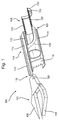
- Figure 1 is a schematic illustration (not to scale) of an embodiment of a gripping device 100.
- the gripping device 100 comprises a jaw portion 102, a first body portion 104, and a second body portion 106.
- the jaw portion 102 comprises a pair of opposing jaws 108 that are moveable relative to one another.
- the jaws 108 are moveable between a fully open position and a fully clamped position, and vice versa, as described in more detail later below with reference to Figures 2 and 3 . Further details of the jaw portion 102 are described in more detail later below with reference to Figure 4 .
- the first body portion 104 comprises a first elongate member 110, a second elongate member 112, a first arm mount 114, and a handle 116.
- the first body portion 104 is a substantially elongate structure having a first end 118 and a second end 120 opposite to the first end 118.
- the jaw portion 102 is attached to the first end 118 of the first body portion 104.
- the second body portion 106 is attached to the second end 120 of the first body portion 104.
- the first elongate member 110 and the second elongate member 112 are mounted together such that they are substantially aligned along their lengths.
- the first elongate member 110 is slidably mounted to second elongate member 112 such that the second elongate member 112 may slide along a length of the first elongate member 110.
- the jaw portion 102 is fixedly attached to a free end of the second elongate member 112 at the first end 118 of the first body portion 104.
- the first elongate member 110 is fixedly attached on top of the first arm mount 114.
- the first arm mount 114 is shaped so as to fit to a forearm of a user as described in more detail later below with reference to Figures 2 and 3 .
- the handle 116 is coupled to the first arm mount 114 at a front end of the first arm mount 114.
- a lower end of the handle portion 116 is coupled to first arm mount 114, while an upper end of the handle portion 116 selectively engages with the first and second elongate portions 110, 112 to selectively fix the relative positions of the first and second elongate members 110, 112.
- the second body portion 106 comprises a hinged chain system 122 and a second arm mount 124.
- the hinged chain system 122 is disposed between the first arm mount 114 at the second end 120 of the first body portion 104 and the second arm mount 124.
- the hinged chain system 122 comprises two chain structures located at opposite sides of the gripping device 100.
- Each chain structure of the hinged chain system 122 has the same or a similar structure to that of a roller chain, and comprises a series of connected chain links attached together to form an elongate chain.
- the second arm mount 124 is shaped so as to fit to an upper arm of a user as described in more detail later below with reference to Figures 2 and 3 .
- the gripping device 100 further comprises a cable 126.
- the cable 126 coupled together the jaw portion 102 and the second arm mount 124.
- the cable 126 is attached at its first end 128 to the jaw portion 102 and at its second end 130, which is opposite to the first end 128, to the second arm mount 124.
- the cable 126 runs from the jaw portion 102, through the first body portion 104 from the first end 118 of the first body portion 104 to the second end 120 of the first body portion 104, and then through a chain structure of the hinged chain system 122 to the second arm mount 124.
- the cable 126 passes through at least part of the first elongate member 110 and then through at least part of the first arm mount 114.
- the cable 126 is housed in a sleeve.
- the cable 126 may be moveable inside the sleeve in a direction along the length of the cable 126.
- the sleeve is fixedly attached to some other component of the gripping device 100, for example, the first arm mount 114.
- Figures 2 and 3 are a schematic illustration (not to scale) showing the gripping device 100 in use.
- the gripping device 100 is fitted to a user's arm 200 such that the first arm mount 114 is fitted to a forearm of the user, and the second arm mount 124 is fitted to the upper arm of the user. Also, the user grips the handle 116 with their hand.
- At least one arm mount 114, 124 comprises an adjustable arm straps to provide support to the arm & forearm.
- the adjustable arm straps may be plastic and coated with a foam material for user comfort.
- the adjustable arm straps allow different sized arms to be accommodated by the gripping device 100.
- the user straightening his or her arm at the elbow i.e. moving from the state shown in Figure 2 to that shown in Figure 3 ), causes the second arm mount 124 to pull the cable 126 in a direction towards the second arm mount 124, i.e. away from the jaw portion 102.
- the cable 126 exerts a pulling force on the jaw portion 102, thereby actuating the jaw portion 102 and causing the jaws 108 to move from their fully open configuration ( Figure 2 ) to their fully clamped or closed configuration ( Figure 3 ).
- the user may operate the gripping device 100 to grip an object.
- the user bending his or her arm at the elbow i.e. moving from the state shown in Figure 3 to that shown in Figure 2 ), causes the second arm mount 124 to release the tension on the cable 126.
- the pulling force exerted on the jaw portion 102 by the cable 126 is reduced or stopped. This may cause the jaws 108 of the jaw portion to move from their fully clamped configuration ( Figure 3 ) back towards their fully open configuration ( Figure 2 ), for example, under action of a sprung return mechanism in the jaw portion 102.
- the cable is sufficiently rigid such that the user bending his or her arm at the elbow (i.e. moving from the state shown in Figure 3 to that shown in Figure 2 ), causes the second arm mount 124 to push the cable 126 in a direction towards the first arm mount 114, i.e. towards the jaw portion 102.
- the cable 126 exerts a pushing force on the jaw portion 102, thereby actuating the jaw portion 102 and causing the jaws 108 to move from their fully clamped configuration ( Figure 3 ) towards their fully open configuration ( Figure 2 ).
- the user may operate the gripping device 100 to release a gripped object.
- Figure 4 is a schematic illustration (not to scale) showing further details of the jaw portion 102.
- Figure 4 shows a top-down view of the jaw portion 102.
- the jaw portion 102 further comprises a ratchet mechanism 400, a return mechanism 404, and a release pin 406.
- the ratchet mechanism 400 is coupled to the jaws 108.
- the ratchet mechanism 400 is configured to allow the jaws 108 to move towards each other, i.e. in a direction from the fully open configuration of the jaws 108 to the fully closed configuration of the jaws 108.
- the ratchet mechanism 400 is further configured to prevent or oppose the jaws 108 moving apart, i.e. in a direction from the fully clamped configuration of the jaws 108 to the fully open configuration of the jaws 108.
- return mechanism 404 is coupled to the jaws 108 and acts on the jaws 108 to force the jaws 108 apart, i.e. to move the jaws 108 in a direction from the fully clamped configuration of the jaws 108 to the fully open configuration of the jaws 108.
- the return mechanism 404 may include a spring mechanism for moving the jaws 108.
- the force with which the ratchet mechanism 400 prevents or opposes the jaws 108 moving apart is much greater than the force with which the return mechanism 404 moves the jaws 108 apart.
- the jaws 108 prevented from moving apart.
- the release pin 406 is coupled to the ratchet mechanism 400. Pressing, or performing some other action, on the release pin 406 causes the release pin 406 to act of the ratchet mechanism 400, thereby disengaging the ratchet mechanism 400 from the jaws 108.
- the ratchet mechanism 400 being disengaged from the jaws 108 means that the ratchet mechanism 400 no longer prevents or opposed the jaws 108 from moving apart, and thus, in this embodiment, the jaws 108 are moved apart by the return mechanism 404.
- the user may operate the gripping device 100 to release a gripped object.
- Figures 5 and 6 are a schematic illustration (not to scale) showing further details of certain parts of the first body portion 104. Figures 5 and 6 show a side view cross section of part of the first body portion 104.
- first elongate member 110 comprise hole (hereinafter “first hole” 500) along its length.
- second elongate member 112 comprises a series of spaced apart through holes (hereinafter “second holes” 502) along its length.
- the handle 116 comprises a protrusion 504 at its upper end.
- the protrusion 504 is sized to fit through the first hole 500 and the second holes 502.
- the handle 116 is coupled at its lower end to the first arm mount 114 via a spring 506 so that the handle may be moved up and down along its length with respect to the other components of the first body portion 104, e.g. with respect to the elongate members 110, 112 and the first arm mount 114.
- the handle 116 may be moved (for example, by the user gripping the handle and moving his or her wrist) up or down along its length between a first position (shown in Figure 5 ), and a second position (shown in Figure 6 ).
- the protrusion 504 of the handle 116 is positioned through aligned first and second holes 500, 502, i.e. through the elongate members 110, 112. This prevents or opposes the second elongate member 112 moving relative to the first elongate member 110, and the relative positions of the elongate members 100, 112 are fixed.
- the spring 506 may force the handle against the elongate members 110, 112.
- the protrusion 504 of the handle 116 does not pass through at least a second hole 502, and preferably also the first hole 500.
- the handle 116 is moved downwards such that a tip of the protrusion 504 is below a lower surface of the second elongate member 112.
- the handle 116 no longer prevents or opposes the second elongate member 112 moving relative to the first elongate member 110.
- the second elongate member 112 may slide along the length of the first elongate member 110 so as to extend or reduce the length of the gripping device 100 (i.e. to increase or decrease a distance between the jaw portion 102 and the arm 200 of the user).
- the new relative positions of the first and second elongate members 100, 112 may be fixed by the handle 116 being returned to its first position.
- the user may move his or her arm to overcome the force exerted on the handle 116 by the spring 506.
- the user may allow the handle 116 to return towards its first position from its second position by releasing the downwards force on the handle 116 and allowing the spring 506 to force the handle upwards.
- the gripping device 100 is advantageously extendible to allow a user to grip objects that are further away.
- the slidable mounting of the elongate members 110, 112 allows for the length of the first body portion 104 to be increased by up to 75%
- the arm mounts tend to uniformly distributes the load across the arm and reduce strain on the user's wrist.
- the gripping device tends to reduce a need for hand motor movements of a user.
- the gripping device tends allow greater loads to be lifted.
- the gripping device tends provide improved control compared to conventional devices.
- the gripping device tends to help prevent repetitive strain injury to a user.
- the inner faces of one or more of the arm mounts may be lined with an easy clean polyethylene foam to provide comfort and improved hygiene.
- An inside surface of the chain systems may be coated with a flexible foam material to prevent injury to the user during operation.
- the handle may be ergonomically designed for the user to hold. This tends to provide support and can help to increase control when using the gripping device.
- the handle may be coated in a thin rubber material to increase friction and provide comfort for the user.
- the jaws may be replaceable.
- the jaws may have standard fitting structures facilitating replacement.
- the gripping device can be reconfigured using different jaws for different tasks.
- the gripping device tends to be easy to manufacture using, for example, Additive Manufacturing techniques.
Landscapes
- Health & Medical Sciences (AREA)
- Engineering & Computer Science (AREA)
- Life Sciences & Earth Sciences (AREA)
- Animal Behavior & Ethology (AREA)
- Transplantation (AREA)
- Biomedical Technology (AREA)
- Heart & Thoracic Surgery (AREA)
- Vascular Medicine (AREA)
- Orthopedic Medicine & Surgery (AREA)
- Veterinary Medicine (AREA)
- General Health & Medical Sciences (AREA)
- Public Health (AREA)
- Human Computer Interaction (AREA)
- Robotics (AREA)
- Mechanical Engineering (AREA)
- Cardiology (AREA)
- Oral & Maxillofacial Surgery (AREA)
- Prostheses (AREA)
Abstract
A gripping device comprising: a first portion (104) having a first end and a second end and comprising a first arm mount (114) for fitting to a user's forearm; a jaw portion (102) comprising a pair of moveable jaws (108) and coupled to the first end of the first portion (104); a second portion (106) coupled to the second end of the first portion (104) and moveable with respect to the first portion (104) and comprising a second arm mount (124) for fitting to a user's upper arm; and a pull member (126) coupled between the jaw portion (102) and the second body portion (106). Movement of the second portion (106) with respect to the first portion (104) moves the pull member (126) causing it to act on the jaw portion (102) to move the jaws (108) from an open position to a clamped position.
Description
- The present invention relates to gripping devices.
- Manual gripping or grabbing tools may be used by people in their daily activities to help with reaching and gripping items.
- Typically these tools require the user to have relatively good gripping or squeezing strength to use.
- Many users have physical limitations, such as arthritis, a disability, poor hand strength and/or poor dexterity. Manual gripping or grabbing tools tend to be difficult or sometimes impossible for such persons with limitations to operate.
- In a first aspect, the present invention provides a gripping device comprising: an elongate first body portion having a first end and a second end opposite to the first end, the first body portion comprising a first arm mount for fitting to a forearm of a user; a jaw portion comprising a pair of jaws moveable relative to each other between a fully open position and a fully clamped position thereof, the jaw portion being coupled to the first end of the first body portion; a second body portion coupled to the second end of the first body portion, and moveable with respect to the first body portion, the second body portion comprising a second arm mount for fitting to an upper arm of a user; and a pull member operatively coupled between the jaw portion and the second body portion, the pull member being at least partially housed within the first body portion. Movement of the second body portion with respect to the first body portion is operative to move the pull member thereby to cause the pull member to act on the jaw portion so as to cause the jaws to move from at or proximate to the fully open position thereof towards the fully clamped position thereof.
- The jaw portion may further comprise a ratchet system configured to oppose movement of the jaws from at or proximate to the fully clamped position thereof towards the fully open position thereof. The jaw portion may further comprise a release mechanism for releasing the ratchet system so as to allow movement of the jaws from at or proximate to the fully clamped position thereof towards the fully open position thereof. The jaw portion may further comprise a first spring mechanism for moving the jaws from at or proximate to the fully clamped position thereof towards the fully open position thereof responsive to the release mechanism releasing the ratchet system.
- The first body portion may be selectively extendible such that a distance between the jaw portion and the second body portion can be varied. The first body portion may further comprise a first elongate member and a second elongate member slidably mounted to the first elongate member. The jaw portion may be coupled to the second elongate member. The second body portion may be coupled to the first elongate member. The first body portion may further comprise a handle portion moveable between a first position and a second position thereof. The first position of the handle portion may be such that the handle portion is engaged with the first elongate member and the second elongate member thereby to fix the relative positions of the first elongate member and the second elongate member. The second position of the handle portion may be such that the handle portion is not engaged with at least one of the first elongate member and the second elongate member thereby allowing the relative movement of the first elongate member and the second elongate member. The first body portion may further comprise a second spring mechanism for moving the handle portion from the second position thereof to the first position thereof.
- When the first arm mount is fitted to the forearm of a user and the second arm mount is fitted the upper arm of that user, the movement of the second body portion with respect to the first body portion that moves the pull member and thereby causes the pull member to act on the jaw portion so as to cause the jaws to move from at or proximate to the fully open position thereof towards the fully clamped position thereof may correspond to the user's arm being straightened.
- Further movement of the second body portion with respect to the first body portion may be operative to move the pull member and thereby causes the pull member to act on the jaw portion so as to cause the jaws to move from at or proximate to the fully clamped position thereof towards the fully open position thereof. The further movement may be in an opposite direction to that of the movement of the second body portion with respect to the first body portion that moves the pull member and thereby causes the pull member to act on the jaw portion so as to cause the jaws to move from at or proximate to the fully open position thereof towards the fully clamped position thereof. When the first arm mount is fitted to the forearm of a user and the second arm mount is fitted the upper arm of that user, the further movement of the second body portion with respect to the first body portion may correspond to the user's arm being bent at an elbow of the user.
- The pull member may be a cable.
- At least part of the pull member may be housed in a sleeve.
- The second body portion may comprise a roller chain system that, when the first arm mount is fitted to the forearm of a user and the second arm mount is fitted the upper arm of that user, is located at an elbow of that user.
- In a second aspect, the present invention provides a method of providing a gripping device, the method comprising: providing an elongate first body portion having a first end and a second end opposite to the first end, the first body portion comprising a first arm mount for fitting to a forearm of a user; coupling a jaw portion the first end of the first body portion, the jaw portion comprising a pair of jaws moveable relative to each other between a fully open position and a fully clamped position thereof; coupling a second body portion to the second end of the first body portion such that the second body portion is moveable with respect to the first body portion, the second body portion comprising a second arm mount for fitting to an upper arm of a user; and coupling a pull member between the jaw portion and the second body portion such that the pull member is at least partially housed within the first body portion and such that movement of the second body portion with respect to the first body portion is operative to move the pull member thereby to cause the pull member to act on the jaw portion so as to cause the jaws to move from at or proximate to the fully open position thereof towards the fully clamped position thereof.
-
-
Figure 1 is a schematic illustration (not to scale) of an embodiment of a gripping device; -
Figure 2 is a schematic illustration (not to scale) showing thegripping device 100 in use; -
Figures 3 is a further schematic illustration (not to scale) showing the gripping device in use; -
Figure 4 is a schematic illustration (not to scale) showing further details of a jaw portion of the gripping device; -
Figure 5 is a schematic illustration (not to scale) showing further details of certain parts of a first body portion of the gripping device; and -
Figure 6 is a further schematic illustration (not to scale) showing further details of certain parts of the first body portion. -
Figure 1 is a schematic illustration (not to scale) of an embodiment of agripping device 100. - In this embodiment, the
gripping device 100 comprises ajaw portion 102, afirst body portion 104, and asecond body portion 106. - The
jaw portion 102 comprises a pair ofopposing jaws 108 that are moveable relative to one another. Thejaws 108 are moveable between a fully open position and a fully clamped position, and vice versa, as described in more detail later below with reference toFigures 2 and 3 . Further details of thejaw portion 102 are described in more detail later below with reference toFigure 4 . - The
first body portion 104 comprises a firstelongate member 110, a secondelongate member 112, afirst arm mount 114, and ahandle 116. - In this embodiment, the
first body portion 104 is a substantially elongate structure having afirst end 118 and asecond end 120 opposite to thefirst end 118. Thejaw portion 102 is attached to thefirst end 118 of thefirst body portion 104. Thesecond body portion 106 is attached to thesecond end 120 of thefirst body portion 104. - The first
elongate member 110 and the secondelongate member 112 are mounted together such that they are substantially aligned along their lengths. The firstelongate member 110 is slidably mounted to secondelongate member 112 such that the secondelongate member 112 may slide along a length of the firstelongate member 110. In this embodiment, thejaw portion 102 is fixedly attached to a free end of the secondelongate member 112 at thefirst end 118 of thefirst body portion 104. - The first
elongate member 110 is fixedly attached on top of thefirst arm mount 114. - The
first arm mount 114 is shaped so as to fit to a forearm of a user as described in more detail later below with reference toFigures 2 and 3 . - The
handle 116 is coupled to thefirst arm mount 114 at a front end of thefirst arm mount 114. In particular, in this embodiment, as described in more detail later below with reference toFigures 5 and 6 , a lower end of thehandle portion 116 is coupled tofirst arm mount 114, while an upper end of thehandle portion 116 selectively engages with the first and secondelongate portions elongate members - The
second body portion 106 comprises ahinged chain system 122 and asecond arm mount 124. Thehinged chain system 122 is disposed between thefirst arm mount 114 at thesecond end 120 of thefirst body portion 104 and thesecond arm mount 124. - In this embodiment, the
hinged chain system 122 comprises two chain structures located at opposite sides of thegripping device 100. Each chain structure of thehinged chain system 122 has the same or a similar structure to that of a roller chain, and comprises a series of connected chain links attached together to form an elongate chain. - The
second arm mount 124 is shaped so as to fit to an upper arm of a user as described in more detail later below with reference toFigures 2 and 3 . - In this embodiment, the
gripping device 100 further comprises acable 126. Thecable 126 coupled together thejaw portion 102 and thesecond arm mount 124. In particular, thecable 126 is attached at itsfirst end 128 to thejaw portion 102 and at itssecond end 130, which is opposite to thefirst end 128, to thesecond arm mount 124. In this embodiment, thecable 126 runs from thejaw portion 102, through thefirst body portion 104 from thefirst end 118 of thefirst body portion 104 to thesecond end 120 of thefirst body portion 104, and then through a chain structure of thehinged chain system 122 to thesecond arm mount 124. In this embodiment, when passing through thefirst body portion 104, thecable 126 passes through at least part of the firstelongate member 110 and then through at least part of thefirst arm mount 114. - In some embodiments, at least part of the
cable 126 is housed in a sleeve. Thecable 126 may be moveable inside the sleeve in a direction along the length of thecable 126. In some embodiments, the sleeve is fixedly attached to some other component of thegripping device 100, for example, thefirst arm mount 114. -
Figures 2 and 3 are a schematic illustration (not to scale) showing thegripping device 100 in use. - In this embodiment, the
gripping device 100 is fitted to a user'sarm 200 such that thefirst arm mount 114 is fitted to a forearm of the user, and thesecond arm mount 124 is fitted to the upper arm of the user. Also, the user grips thehandle 116 with their hand. - Preferably, at least one
arm mount gripping device 100. - In
Figure 2 , the user'sarm 200 is bent at the elbow. In this state, thecable 126 within thegripping device 100 is relatively slack. Also, in this state, thejaws 108 of thejaw portion 102 are in their fully open configuration. - The user straightening his or her arm at the elbow (i.e. moving from the state shown in
Figure 2 to that shown inFigure 3 ), causes thesecond arm mount 124 to pull thecable 126 in a direction towards thesecond arm mount 124, i.e. away from thejaw portion 102. Thus, thecable 126 exerts a pulling force on thejaw portion 102, thereby actuating thejaw portion 102 and causing thejaws 108 to move from their fully open configuration (Figure 2 ) to their fully clamped or closed configuration (Figure 3 ). - In this way, the user may operate the
gripping device 100 to grip an object. - In some embodiments, the user bending his or her arm at the elbow (i.e. moving from the state shown in
Figure 3 to that shown inFigure 2 ), causes thesecond arm mount 124 to release the tension on thecable 126. Thus, the pulling force exerted on thejaw portion 102 by thecable 126 is reduced or stopped. This may cause thejaws 108 of the jaw portion to move from their fully clamped configuration (Figure 3 ) back towards their fully open configuration (Figure 2 ), for example, under action of a sprung return mechanism in thejaw portion 102. - In some embodiments, the cable is sufficiently rigid such that the user bending his or her arm at the elbow (i.e. moving from the state shown in
Figure 3 to that shown inFigure 2 ), causes thesecond arm mount 124 to push thecable 126 in a direction towards thefirst arm mount 114, i.e. towards thejaw portion 102. Thus, thecable 126 exerts a pushing force on thejaw portion 102, thereby actuating thejaw portion 102 and causing thejaws 108 to move from their fully clamped configuration (Figure 3 ) towards their fully open configuration (Figure 2 ). - In this way, the user may operate the
gripping device 100 to release a gripped object. -
Figure 4 is a schematic illustration (not to scale) showing further details of thejaw portion 102.Figure 4 shows a top-down view of thejaw portion 102. - In this embodiment, the
jaw portion 102 further comprises aratchet mechanism 400, areturn mechanism 404, and arelease pin 406. - In this embodiment, the
ratchet mechanism 400 is coupled to thejaws 108. Theratchet mechanism 400 is configured to allow thejaws 108 to move towards each other, i.e. in a direction from the fully open configuration of thejaws 108 to the fully closed configuration of thejaws 108. Theratchet mechanism 400 is further configured to prevent or oppose thejaws 108 moving apart, i.e. in a direction from the fully clamped configuration of thejaws 108 to the fully open configuration of thejaws 108. - In this embodiment,
return mechanism 404 is coupled to thejaws 108 and acts on thejaws 108 to force thejaws 108 apart, i.e. to move thejaws 108 in a direction from the fully clamped configuration of thejaws 108 to the fully open configuration of thejaws 108. Thereturn mechanism 404 may include a spring mechanism for moving thejaws 108. - In this embodiment, the force with which the
ratchet mechanism 400 prevents or opposes thejaws 108 moving apart is much greater than the force with which thereturn mechanism 404 moves thejaws 108 apart. Thus, when theratchet mechanism 400 is engaged with thejaws 108, thejaws 108 prevented from moving apart. - The
release pin 406 is coupled to theratchet mechanism 400. Pressing, or performing some other action, on therelease pin 406 causes therelease pin 406 to act of theratchet mechanism 400, thereby disengaging theratchet mechanism 400 from thejaws 108. Theratchet mechanism 400 being disengaged from thejaws 108 means that theratchet mechanism 400 no longer prevents or opposed thejaws 108 from moving apart, and thus, in this embodiment, thejaws 108 are moved apart by thereturn mechanism 404. - In this way, i.e. by operating the
release pin 406, the user may operate thegripping device 100 to release a gripped object. -
Figures 5 and 6 are a schematic illustration (not to scale) showing further details of certain parts of thefirst body portion 104.Figures 5 and 6 show a side view cross section of part of thefirst body portion 104. - In this embodiment, the first
elongate member 110 comprise hole (hereinafter "first hole" 500) along its length. Also, the secondelongate member 112 comprises a series of spaced apart through holes (hereinafter "second holes" 502) along its length. - The
handle 116 comprises aprotrusion 504 at its upper end. Theprotrusion 504 is sized to fit through thefirst hole 500 and thesecond holes 502. - The
handle 116 is coupled at its lower end to thefirst arm mount 114 via aspring 506 so that the handle may be moved up and down along its length with respect to the other components of thefirst body portion 104, e.g. with respect to theelongate members first arm mount 114. - In particular, in this embodiment, the
handle 116 may be moved (for example, by the user gripping the handle and moving his or her wrist) up or down along its length between a first position (shown inFigure 5 ), and a second position (shown inFigure 6 ). - In its first position (
Figure 5 ), theprotrusion 504 of thehandle 116 is positioned through aligned first andsecond holes elongate members elongate member 112 moving relative to the firstelongate member 110, and the relative positions of theelongate members spring 506 may force the handle against theelongate members - In its second position (
Figure 6 ), theprotrusion 504 of thehandle 116 does not pass through at least asecond hole 502, and preferably also thefirst hole 500. In other words, thehandle 116 is moved downwards such that a tip of theprotrusion 504 is below a lower surface of the secondelongate member 112. In this position, thehandle 116 no longer prevents or opposes the secondelongate member 112 moving relative to the firstelongate member 110. Thus, the secondelongate member 112 may slide along the length of the firstelongate member 110 so as to extend or reduce the length of the gripping device 100 (i.e. to increase or decrease a distance between thejaw portion 102 and thearm 200 of the user). The new relative positions of the first and secondelongate members handle 116 being returned to its first position. - To move the
handle 116 from its first position to its second position, the user may move his or her arm to overcome the force exerted on thehandle 116 by thespring 506. The user may allow thehandle 116 to return towards its first position from its second position by releasing the downwards force on thehandle 116 and allowing thespring 506 to force the handle upwards. - Thus, the
gripping device 100 is advantageously extendible to allow a user to grip objects that are further away. In some embodiments, the slidable mounting of theelongate members first body portion 104 to be increased by up to 75% - Advantageously, the arm mounts tend to uniformly distributes the load across the arm and reduce strain on the user's wrist.
- The gripping device tends to reduce a need for hand motor movements of a user. The gripping device tends allow greater loads to be lifted. The gripping device tends provide improved control compared to conventional devices. The gripping device tends to help prevent repetitive strain injury to a user.
- The inner faces of one or more of the arm mounts may be lined with an easy clean polyethylene foam to provide comfort and improved hygiene.
- An inside surface of the chain systems may be coated with a flexible foam material to prevent injury to the user during operation.
- The handle may be ergonomically designed for the user to hold. This tends to provide support and can help to increase control when using the gripping device. The handle may be coated in a thin rubber material to increase friction and provide comfort for the user.
- Advantageously, the jaws may be replaceable. The jaws may have standard fitting structures facilitating replacement. Thus, the gripping device can be reconfigured using different jaws for different tasks.
- Advantageously, the gripping device tends to be easy to manufacture using, for example, Additive Manufacturing techniques.
- A specific embodiment of a gripping device and its method of use has been described for the purposes of illustrating the manner in which the invention is made and used. It should be understood that the implementation of other variations and modifications of the invention and its various aspects will be apparent to one skilled in the art, and that the invention is not limited by the specific embodiment described. Therefore, it is contemplated to cover the present invention and any and all modifications, variations, or equivalents that fall within the scope of the basic underlying principles disclosed and claimed herein.
Claims (15)
- A gripping device comprising:an elongate first body portion (104) having a first end and a second end opposite to the first end, the first body portion (104) comprising a first arm mount (114) for fitting to a forearm of a user;a jaw portion (102) comprising a pair of jaws (108) moveable relative to each other between a fully open position and a fully clamped position thereof, the jaw portion (102) being coupled to the first end of the first body portion (104);a second body portion (106) coupled to the second end of the first body portion (104), and moveable with respect to the first body portion (104), the second body portion (106) comprising a second arm mount (124) for fitting to an upper arm of a user; anda pull member (126) operatively coupled between the jaw portion (102) and the second body portion (106), the pull member (126) being at least partially housed within the first body portion (104); whereinmovement of the second body portion (106) with respect to the first body portion (104) is operative to move the pull member (126) thereby to cause the pull member (126) to act on the jaw portion (102) so as to cause the jaws (108) to move from at or proximate to the fully open position thereof towards the fully clamped position thereof.
- A gripping device (100) according to claim 1, wherein the jaw portion (102) further comprises a ratchet system (400) configured to oppose movement of the jaws (108) from at or proximate to the fully clamped position thereof towards the fully open position thereof.
- A gripping device (100) according to claim 2, wherein the jaw portion (102) further comprises a release mechanism (404) for releasing the ratchet system (400) so as to allow movement of the jaws (108) from at or proximate to the fully clamped position thereof towards the fully open position thereof.
- A gripping device (100) according to claim 3, wherein the jaw portion (102) further comprises a first spring mechanism for moving the jaws (108) from at or proximate to the fully clamped position thereof towards the fully open position thereof responsive to the release mechanism (404) releasing the ratchet system (400).
- A gripping device (100) according to any of claims 1 to 4, wherein the first body portion (104) is selectively extendible such that a distance between the jaw portion (102) and the second body portion (106) can be varied.
- A gripping device (100) according to any of claims 1 to 5, wherein:the first body portion (104) further comprises:a first elongate member (110); anda second elongate member (112) slidably mounted to the first elongate member (110);the jaw portion (102) is coupled to the second elongate member (112); andthe second body portion (106) is coupled to the first elongate member (110).
- A gripping device (100) according to claim 6, wherein:the first body portion (104) further comprises a handle portion (116) moveable between a first position and a second position thereof;the first position of the handle portion (116) is such that the handle portion (116) is engaged with the first elongate member (110) and the second elongate member (112) thereby to fix the relative positions of the first elongate member (110) and the second elongate member (112); andthe second position of the handle portion (116) is such that the handle portion (116) is not engaged with at least one of the first elongate member (110) and the second elongate member (112) thereby allowing the relative movement of the first elongate member (110) and the second elongate member (112).
- A gripping device (100) according to claim 7, wherein the first body portion (104) further comprises a second spring mechanism (506) for moving the handle portion (116) from the second position thereof to the first position thereof.
- A gripping device (100) according to any of claims 1 to 8, wherein, when the first arm mount (114) is fitted to the forearm of a user and the second arm mount (124) is fitted the upper arm of that user, the movement of the second body portion (106) with respect to the first body portion (104) that moves the pull member (126) and thereby causes the pull member (126) to act on the jaw portion (102) so as to cause the jaws (108) to move from at or proximate to the fully open position thereof towards the fully clamped position thereof corresponds to the user's arm being straightened.
- A gripping device (100) according to any of claims 1 to 9, wherein:further movement of the second body portion (106) with respect to the first body portion (104) is operative to move the pull member (126) and thereby causes the pull member (126) to act on the jaw portion (102) so as to cause the jaws (108) to move from at or proximate to the fully clamped position thereof towards the fully open position thereof; andthe further movement is in an opposite direction to that of the movement of the second body portion (106) with respect to the first body portion (104) that moves the pull member (126) and thereby causes the pull member (126) to act on the jaw portion (102) so as to cause the jaws (108) to move from at or proximate to the fully open position thereof towards the fully clamped position thereof.
- A gripping device (100) according to claim 10, wherein, when the first arm mount (114) is fitted to the forearm of a user and the second arm mount (124) is fitted the upper arm of that user, the further movement of the second body portion (106) with respect to the first body portion (104) corresponds to the user's arm being bent at an elbow of the user.
- A gripping device (100) according to any of claims 1 to 11, wherein the pull member (126) is a cable.
- A gripping device (100) according to any of claims 1 to 12, wherein at least part of the pull member (126) is housed in a sleeve.
- A gripping device (100) according to any of claims 1 to 13, wherein the second body portion (106) comprises a roller chain system (122) that, when the first arm mount (114) is fitted to the forearm of a user and the second arm mount (124) is fitted the upper arm of that user, is located at an elbow of that user.
- A method of providing a gripping device (100), the method comprising:providing an elongate first body portion (104) having a first end and a second end opposite to the first end, the first body portion (104) comprising a first arm mount (114) for fitting to a forearm of a user;coupling a jaw portion (102) the first end of the first body portion (104), the jaw portion (102) comprising a pair of jaws (108) moveable relative to each other between a fully open position and a fully clamped position thereof;coupling a second body portion (106) to the second end of the first body portion (104) such that the second body portion (106) is moveable with respect to the first body portion (104), the second body portion (106) comprising a second arm mount (124) for fitting to an upper arm of a user; andcoupling a pull member (126) between the jaw portion (102) and the second body portion (106) such that the pull member (126) is at least partially housed within the first body portion (104) and such that movement of the second body portion (106) with respect to the first body portion (104) is operative to move the pull member (126) thereby to cause the pull member (126) to act on the jaw portion (102) so as to cause the jaws (108) to move from at or proximate to the fully open position thereof towards the fully clamped position thereof.
Priority Applications (1)
| Application Number | Priority Date | Filing Date | Title |
|---|---|---|---|
| EP16275006.1A EP3189815A1 (en) | 2016-01-06 | 2016-01-06 | Gripping device |
Applications Claiming Priority (1)
| Application Number | Priority Date | Filing Date | Title |
|---|---|---|---|
| EP16275006.1A EP3189815A1 (en) | 2016-01-06 | 2016-01-06 | Gripping device |
Publications (1)
| Publication Number | Publication Date |
|---|---|
| EP3189815A1 true EP3189815A1 (en) | 2017-07-12 |
Family
ID=55072598
Family Applications (1)
| Application Number | Title | Priority Date | Filing Date |
|---|---|---|---|
| EP16275006.1A Ceased EP3189815A1 (en) | 2016-01-06 | 2016-01-06 | Gripping device |
Country Status (1)
| Country | Link |
|---|---|
| EP (1) | EP3189815A1 (en) |
Cited By (1)
| Publication number | Priority date | Publication date | Assignee | Title |
|---|---|---|---|---|
| DE102018205762A1 (en) * | 2018-04-16 | 2019-10-17 | Ass Maschinenbau Gmbh | Tool system for people with reduced grip or limited motor skills |
Citations (4)
| Publication number | Priority date | Publication date | Assignee | Title |
|---|---|---|---|---|
| US3020908A (en) * | 1960-06-27 | 1962-02-13 | All American Eng Co | Mechanical hand |
| US3967321A (en) * | 1975-02-05 | 1976-07-06 | Indiana University Foundation | Electrically driven hand orthosis device for providing finger prehension |
| US4758035A (en) * | 1987-04-24 | 1988-07-19 | Harrington Arthritis Research Center | Self-gripping reacher |
| EP2737880A1 (en) * | 2012-11-29 | 2014-06-04 | Invencon ApS | Aid grabbing tool with force activated gripping function |
-
2016
- 2016-01-06 EP EP16275006.1A patent/EP3189815A1/en not_active Ceased
Patent Citations (4)
| Publication number | Priority date | Publication date | Assignee | Title |
|---|---|---|---|---|
| US3020908A (en) * | 1960-06-27 | 1962-02-13 | All American Eng Co | Mechanical hand |
| US3967321A (en) * | 1975-02-05 | 1976-07-06 | Indiana University Foundation | Electrically driven hand orthosis device for providing finger prehension |
| US4758035A (en) * | 1987-04-24 | 1988-07-19 | Harrington Arthritis Research Center | Self-gripping reacher |
| EP2737880A1 (en) * | 2012-11-29 | 2014-06-04 | Invencon ApS | Aid grabbing tool with force activated gripping function |
Cited By (2)
| Publication number | Priority date | Publication date | Assignee | Title |
|---|---|---|---|---|
| DE102018205762A1 (en) * | 2018-04-16 | 2019-10-17 | Ass Maschinenbau Gmbh | Tool system for people with reduced grip or limited motor skills |
| DE102018205762B4 (en) | 2018-04-16 | 2019-10-24 | Ass Maschinenbau Gmbh | Tool system for people with reduced grip or limited motor skills |
Similar Documents
| Publication | Publication Date | Title |
|---|---|---|
| US6551226B1 (en) | Adjustment apparatus for exercise machine | |
| US4374600A (en) | Lock-type gripping device for handicapped persons | |
| US4758035A (en) | Self-gripping reacher | |
| KR101939514B1 (en) | Posture holder | |
| US8777287B2 (en) | Sliding handle reacher | |
| US9861499B2 (en) | Gripping device with switchable opening modes | |
| WO2014195373A1 (en) | Lifting aid worn on the body | |
| US20190111545A1 (en) | Load induced mechanism system | |
| CN102026780A (en) | Pick up device with telescoping tube | |
| US919731A (en) | Lifting device. | |
| US4993766A (en) | Mechanical gripping aid for handicapped persons | |
| US5357677A (en) | Toe nail clipper apparatus | |
| EP2703569A1 (en) | Height adjustment assembly for use in bathing supplies | |
| DK177548B1 (en) | Aid grabbing tool with hand operated gripper that can be pushed aside | |
| US6453851B1 (en) | Animal restraint leash | |
| EP2737880A1 (en) | Aid grabbing tool with force activated gripping function | |
| WO2014196537A1 (en) | Opening implement for accessory catch | |
| US20150305452A1 (en) | Cane with Spring-Actuated Gripper | |
| US10016082B1 (en) | Garment removal apparatus and method | |
| EP1790390A1 (en) | Gymnastic machine | |
| GB2546080A (en) | Gripping device | |
| US5941587A (en) | Grasping tool | |
| KR102352899B1 (en) | Tenodesis action support device | |
| EP3574882B1 (en) | Hoist with handle | |
| NL2015789B1 (en) | A handgrip for a leash |
Legal Events
| Date | Code | Title | Description |
|---|---|---|---|
| PUAI | Public reference made under article 153(3) epc to a published international application that has entered the european phase |
Free format text: ORIGINAL CODE: 0009012 |
|
| AK | Designated contracting states |
Kind code of ref document: A1 Designated state(s): AL AT BE BG CH CY CZ DE DK EE ES FI FR GB GR HR HU IE IS IT LI LT LU LV MC MK MT NL NO PL PT RO RS SE SI SK SM TR |
|
| AX | Request for extension of the european patent |
Extension state: BA ME |
|
| 18R | Application refused |
Effective date: 20170804 |