EP3188873B1 - Electroslag cladding method - Google Patents
Electroslag cladding method Download PDFInfo
- Publication number
- EP3188873B1 EP3188873B1 EP15825945.7A EP15825945A EP3188873B1 EP 3188873 B1 EP3188873 B1 EP 3188873B1 EP 15825945 A EP15825945 A EP 15825945A EP 3188873 B1 EP3188873 B1 EP 3188873B1
- Authority
- EP
- European Patent Office
- Prior art keywords
- wire
- cladding
- metal cored
- electroslag
- composition
- Prior art date
- Legal status (The legal status is an assumption and is not a legal conclusion. Google has not performed a legal analysis and makes no representation as to the accuracy of the status listed.)
- Active
Links
Images


Classifications
-
- B—PERFORMING OPERATIONS; TRANSPORTING
- B23—MACHINE TOOLS; METAL-WORKING NOT OTHERWISE PROVIDED FOR
- B23K—SOLDERING OR UNSOLDERING; WELDING; CLADDING OR PLATING BY SOLDERING OR WELDING; CUTTING BY APPLYING HEAT LOCALLY, e.g. FLAME CUTTING; WORKING BY LASER BEAM
- B23K25/00—Slag welding, i.e. using a heated layer or mass of powder, slag or the like in contact with the material to be joined
- B23K25/005—Welding for purposes other than joining, e.g. build-up welding
-
- B—PERFORMING OPERATIONS; TRANSPORTING
- B23—MACHINE TOOLS; METAL-WORKING NOT OTHERWISE PROVIDED FOR
- B23K—SOLDERING OR UNSOLDERING; WELDING; CLADDING OR PLATING BY SOLDERING OR WELDING; CUTTING BY APPLYING HEAT LOCALLY, e.g. FLAME CUTTING; WORKING BY LASER BEAM
- B23K35/00—Rods, electrodes, materials, or media, for use in soldering, welding, or cutting
- B23K35/02—Rods, electrodes, materials, or media, for use in soldering, welding, or cutting characterised by mechanical features, e.g. shape
- B23K35/0255—Rods, electrodes, materials, or media, for use in soldering, welding, or cutting characterised by mechanical features, e.g. shape for use in welding
-
- B—PERFORMING OPERATIONS; TRANSPORTING
- B23—MACHINE TOOLS; METAL-WORKING NOT OTHERWISE PROVIDED FOR
- B23K—SOLDERING OR UNSOLDERING; WELDING; CLADDING OR PLATING BY SOLDERING OR WELDING; CUTTING BY APPLYING HEAT LOCALLY, e.g. FLAME CUTTING; WORKING BY LASER BEAM
- B23K35/00—Rods, electrodes, materials, or media, for use in soldering, welding, or cutting
- B23K35/02—Rods, electrodes, materials, or media, for use in soldering, welding, or cutting characterised by mechanical features, e.g. shape
- B23K35/0255—Rods, electrodes, materials, or media, for use in soldering, welding, or cutting characterised by mechanical features, e.g. shape for use in welding
- B23K35/0261—Rods, electrodes or wires
-
- B—PERFORMING OPERATIONS; TRANSPORTING
- B23—MACHINE TOOLS; METAL-WORKING NOT OTHERWISE PROVIDED FOR
- B23K—SOLDERING OR UNSOLDERING; WELDING; CLADDING OR PLATING BY SOLDERING OR WELDING; CUTTING BY APPLYING HEAT LOCALLY, e.g. FLAME CUTTING; WORKING BY LASER BEAM
- B23K35/00—Rods, electrodes, materials, or media, for use in soldering, welding, or cutting
- B23K35/02—Rods, electrodes, materials, or media, for use in soldering, welding, or cutting characterised by mechanical features, e.g. shape
- B23K35/0255—Rods, electrodes, materials, or media, for use in soldering, welding, or cutting characterised by mechanical features, e.g. shape for use in welding
- B23K35/0261—Rods, electrodes or wires
- B23K35/0266—Rods, electrodes or wires flux-cored
-
- B—PERFORMING OPERATIONS; TRANSPORTING
- B23—MACHINE TOOLS; METAL-WORKING NOT OTHERWISE PROVIDED FOR
- B23K—SOLDERING OR UNSOLDERING; WELDING; CLADDING OR PLATING BY SOLDERING OR WELDING; CUTTING BY APPLYING HEAT LOCALLY, e.g. FLAME CUTTING; WORKING BY LASER BEAM
- B23K35/00—Rods, electrodes, materials, or media, for use in soldering, welding, or cutting
- B23K35/22—Rods, electrodes, materials, or media, for use in soldering, welding, or cutting characterised by the composition or nature of the material
- B23K35/24—Selection of soldering or welding materials proper
- B23K35/30—Selection of soldering or welding materials proper with the principal constituent melting at less than 1550°C
-
- B—PERFORMING OPERATIONS; TRANSPORTING
- B23—MACHINE TOOLS; METAL-WORKING NOT OTHERWISE PROVIDED FOR
- B23K—SOLDERING OR UNSOLDERING; WELDING; CLADDING OR PLATING BY SOLDERING OR WELDING; CUTTING BY APPLYING HEAT LOCALLY, e.g. FLAME CUTTING; WORKING BY LASER BEAM
- B23K35/00—Rods, electrodes, materials, or media, for use in soldering, welding, or cutting
- B23K35/22—Rods, electrodes, materials, or media, for use in soldering, welding, or cutting characterised by the composition or nature of the material
- B23K35/24—Selection of soldering or welding materials proper
- B23K35/30—Selection of soldering or welding materials proper with the principal constituent melting at less than 1550°C
- B23K35/3033—Ni as the principal constituent
-
- B—PERFORMING OPERATIONS; TRANSPORTING
- B23—MACHINE TOOLS; METAL-WORKING NOT OTHERWISE PROVIDED FOR
- B23K—SOLDERING OR UNSOLDERING; WELDING; CLADDING OR PLATING BY SOLDERING OR WELDING; CUTTING BY APPLYING HEAT LOCALLY, e.g. FLAME CUTTING; WORKING BY LASER BEAM
- B23K35/00—Rods, electrodes, materials, or media, for use in soldering, welding, or cutting
- B23K35/22—Rods, electrodes, materials, or media, for use in soldering, welding, or cutting characterised by the composition or nature of the material
- B23K35/24—Selection of soldering or welding materials proper
- B23K35/30—Selection of soldering or welding materials proper with the principal constituent melting at less than 1550°C
- B23K35/3053—Fe as the principal constituent
- B23K35/3066—Fe as the principal constituent with Ni as next major constituent
-
- B—PERFORMING OPERATIONS; TRANSPORTING
- B23—MACHINE TOOLS; METAL-WORKING NOT OTHERWISE PROVIDED FOR
- B23K—SOLDERING OR UNSOLDERING; WELDING; CLADDING OR PLATING BY SOLDERING OR WELDING; CUTTING BY APPLYING HEAT LOCALLY, e.g. FLAME CUTTING; WORKING BY LASER BEAM
- B23K35/00—Rods, electrodes, materials, or media, for use in soldering, welding, or cutting
- B23K35/22—Rods, electrodes, materials, or media, for use in soldering, welding, or cutting characterised by the composition or nature of the material
- B23K35/24—Selection of soldering or welding materials proper
- B23K35/30—Selection of soldering or welding materials proper with the principal constituent melting at less than 1550°C
- B23K35/3053—Fe as the principal constituent
- B23K35/308—Fe as the principal constituent with Cr as next major constituent
-
- B—PERFORMING OPERATIONS; TRANSPORTING
- B23—MACHINE TOOLS; METAL-WORKING NOT OTHERWISE PROVIDED FOR
- B23K—SOLDERING OR UNSOLDERING; WELDING; CLADDING OR PLATING BY SOLDERING OR WELDING; CUTTING BY APPLYING HEAT LOCALLY, e.g. FLAME CUTTING; WORKING BY LASER BEAM
- B23K35/00—Rods, electrodes, materials, or media, for use in soldering, welding, or cutting
- B23K35/22—Rods, electrodes, materials, or media, for use in soldering, welding, or cutting characterised by the composition or nature of the material
- B23K35/24—Selection of soldering or welding materials proper
- B23K35/30—Selection of soldering or welding materials proper with the principal constituent melting at less than 1550°C
- B23K35/3053—Fe as the principal constituent
- B23K35/308—Fe as the principal constituent with Cr as next major constituent
- B23K35/3086—Fe as the principal constituent with Cr as next major constituent containing Ni or Mn
-
- C—CHEMISTRY; METALLURGY
- C22—METALLURGY; FERROUS OR NON-FERROUS ALLOYS; TREATMENT OF ALLOYS OR NON-FERROUS METALS
- C22C—ALLOYS
- C22C19/00—Alloys based on nickel or cobalt
- C22C19/03—Alloys based on nickel or cobalt based on nickel
-
- C—CHEMISTRY; METALLURGY
- C22—METALLURGY; FERROUS OR NON-FERROUS ALLOYS; TREATMENT OF ALLOYS OR NON-FERROUS METALS
- C22C—ALLOYS
- C22C19/00—Alloys based on nickel or cobalt
- C22C19/03—Alloys based on nickel or cobalt based on nickel
- C22C19/05—Alloys based on nickel or cobalt based on nickel with chromium
-
- C—CHEMISTRY; METALLURGY
- C22—METALLURGY; FERROUS OR NON-FERROUS ALLOYS; TREATMENT OF ALLOYS OR NON-FERROUS METALS
- C22C—ALLOYS
- C22C19/00—Alloys based on nickel or cobalt
- C22C19/03—Alloys based on nickel or cobalt based on nickel
- C22C19/05—Alloys based on nickel or cobalt based on nickel with chromium
- C22C19/051—Alloys based on nickel or cobalt based on nickel with chromium and Mo or W
- C22C19/055—Alloys based on nickel or cobalt based on nickel with chromium and Mo or W with the maximum Cr content being at least 20% but less than 30%
-
- C—CHEMISTRY; METALLURGY
- C22—METALLURGY; FERROUS OR NON-FERROUS ALLOYS; TREATMENT OF ALLOYS OR NON-FERROUS METALS
- C22C—ALLOYS
- C22C19/00—Alloys based on nickel or cobalt
- C22C19/03—Alloys based on nickel or cobalt based on nickel
- C22C19/05—Alloys based on nickel or cobalt based on nickel with chromium
- C22C19/058—Alloys based on nickel or cobalt based on nickel with chromium without Mo and W
-
- C—CHEMISTRY; METALLURGY
- C22—METALLURGY; FERROUS OR NON-FERROUS ALLOYS; TREATMENT OF ALLOYS OR NON-FERROUS METALS
- C22C—ALLOYS
- C22C38/00—Ferrous alloys, e.g. steel alloys
- C22C38/002—Ferrous alloys, e.g. steel alloys containing In, Mg, or other elements not provided for in one single group C22C38/001 - C22C38/60
-
- C—CHEMISTRY; METALLURGY
- C22—METALLURGY; FERROUS OR NON-FERROUS ALLOYS; TREATMENT OF ALLOYS OR NON-FERROUS METALS
- C22C—ALLOYS
- C22C38/00—Ferrous alloys, e.g. steel alloys
- C22C38/02—Ferrous alloys, e.g. steel alloys containing silicon
-
- C—CHEMISTRY; METALLURGY
- C22—METALLURGY; FERROUS OR NON-FERROUS ALLOYS; TREATMENT OF ALLOYS OR NON-FERROUS METALS
- C22C—ALLOYS
- C22C38/00—Ferrous alloys, e.g. steel alloys
- C22C38/04—Ferrous alloys, e.g. steel alloys containing manganese
-
- C—CHEMISTRY; METALLURGY
- C22—METALLURGY; FERROUS OR NON-FERROUS ALLOYS; TREATMENT OF ALLOYS OR NON-FERROUS METALS
- C22C—ALLOYS
- C22C38/00—Ferrous alloys, e.g. steel alloys
- C22C38/06—Ferrous alloys, e.g. steel alloys containing aluminium
-
- C—CHEMISTRY; METALLURGY
- C22—METALLURGY; FERROUS OR NON-FERROUS ALLOYS; TREATMENT OF ALLOYS OR NON-FERROUS METALS
- C22C—ALLOYS
- C22C38/00—Ferrous alloys, e.g. steel alloys
- C22C38/18—Ferrous alloys, e.g. steel alloys containing chromium
- C22C38/40—Ferrous alloys, e.g. steel alloys containing chromium with nickel
-
- C—CHEMISTRY; METALLURGY
- C22—METALLURGY; FERROUS OR NON-FERROUS ALLOYS; TREATMENT OF ALLOYS OR NON-FERROUS METALS
- C22C—ALLOYS
- C22C38/00—Ferrous alloys, e.g. steel alloys
- C22C38/18—Ferrous alloys, e.g. steel alloys containing chromium
- C22C38/40—Ferrous alloys, e.g. steel alloys containing chromium with nickel
- C22C38/42—Ferrous alloys, e.g. steel alloys containing chromium with nickel with copper
-
- C—CHEMISTRY; METALLURGY
- C22—METALLURGY; FERROUS OR NON-FERROUS ALLOYS; TREATMENT OF ALLOYS OR NON-FERROUS METALS
- C22C—ALLOYS
- C22C38/00—Ferrous alloys, e.g. steel alloys
- C22C38/18—Ferrous alloys, e.g. steel alloys containing chromium
- C22C38/40—Ferrous alloys, e.g. steel alloys containing chromium with nickel
- C22C38/44—Ferrous alloys, e.g. steel alloys containing chromium with nickel with molybdenum or tungsten
-
- C—CHEMISTRY; METALLURGY
- C22—METALLURGY; FERROUS OR NON-FERROUS ALLOYS; TREATMENT OF ALLOYS OR NON-FERROUS METALS
- C22C—ALLOYS
- C22C38/00—Ferrous alloys, e.g. steel alloys
- C22C38/18—Ferrous alloys, e.g. steel alloys containing chromium
- C22C38/40—Ferrous alloys, e.g. steel alloys containing chromium with nickel
- C22C38/48—Ferrous alloys, e.g. steel alloys containing chromium with nickel with niobium or tantalum
-
- C—CHEMISTRY; METALLURGY
- C22—METALLURGY; FERROUS OR NON-FERROUS ALLOYS; TREATMENT OF ALLOYS OR NON-FERROUS METALS
- C22C—ALLOYS
- C22C38/00—Ferrous alloys, e.g. steel alloys
- C22C38/18—Ferrous alloys, e.g. steel alloys containing chromium
- C22C38/40—Ferrous alloys, e.g. steel alloys containing chromium with nickel
- C22C38/50—Ferrous alloys, e.g. steel alloys containing chromium with nickel with titanium or zirconium
-
- C—CHEMISTRY; METALLURGY
- C22—METALLURGY; FERROUS OR NON-FERROUS ALLOYS; TREATMENT OF ALLOYS OR NON-FERROUS METALS
- C22C—ALLOYS
- C22C38/00—Ferrous alloys, e.g. steel alloys
- C22C38/18—Ferrous alloys, e.g. steel alloys containing chromium
- C22C38/40—Ferrous alloys, e.g. steel alloys containing chromium with nickel
- C22C38/58—Ferrous alloys, e.g. steel alloys containing chromium with nickel with more than 1.5% by weight of manganese
Definitions
- the Invention relates to electroslag cladding. More specifically, the invention relates to a hybrid electroslag cladding method according to the preamble of claim 1.
- Cladding is a well established overlay welding technique that provides a layer of alloyed steel onto the surface of a metal device for, inter alia, wear and corrosion protection. For instance, pressure vessels are exposed to corrosive media under high pressure and high temperatures and generally require a cladding layer. Other example devices to which protective cladding layers are applied include reactors, heat exchangers and separators.
- the cladding has to meet specific requirements depending on the Intended use of the device.
- the deposited weld overlay grade is prescribed by engineering companies that design the device. Some examples are: Nickel Base Alloy 400, 600, 625, 825, and others, and Stainless Steel SS 308L, 316L. 317L, 347, Duplex, Super Duplex, and others.
- the grade requirements differ; for instance, when cladding Nickel Base Alloy 625 in Carbon steel or low-alloyed steel, a low Fe content ⁇ 5 wt% is a major requirement, and when cladding e.g. Stainless Steel SS347 on carbon steel or low alloyed steel, different stainless steel chemistry is required depending on the application.
- the current state of the art comprises numerous cladding techniques.
- the submerged-arc strip cladding process uses an arc and generally requires several layers to achieve specified requirements, see e.g. "Submerged-arc strip cladding of continuous casting rollerstiti", in: Svetsaren nr 1, 2001, pages 17 to 19 .
- the electroslag process has been used with a strip electrode and a flux-cored wire (" Modification of the electroslag process opens up possibilities with regard to weld surfacing", in: Welding and Cutting 5 (2006) No. 4, pages 215 to 220 ), however, for the purpose of Hardfacing rather than corrosion resistant cladding and with chemical compositions in the hardfacing layer which are incompatible with typical weld overly grades for corrosion resistant cladding.
- Hardfacing is the method of weld overlay of hard facing material for mechanical wear resistance. This is mainly used in the cement, mining and steel industry.
- the object of the invention is thus to provide a hybrid electroslag cladding method that allows the fast deposition of a single cladding layer that meets high overlay grades with respect to the desired cladding chemistry.
- the invention thus provides hybrid electroslag cladding, i.e. arcless cladding with both a strip electrode and an alloyed metal cored wire, that allows very fast (typically > 27 cm/min) cladding of a preferably single cladding layer of desired thickness (typically 4.5 to 5.5 mm) and that meets the typical weld overlay grade chemical requirements (e.g. Fe ⁇ 5 wt% for Nickel Base Alloy 625).
- the invention provides a hybrid electroslag cladding method, comprising: providing a workpiece to be cladded; guiding a strip electrode onto the surface of the workpiece; cladding the strip electrode onto the surface of the workpiece using electroslag cladding; and guiding a metal cored hybrid cladding wire into the weld puddle of the strip electrode for controlling the chemical composition of the cladding; using a strip electrode with a given chemical composition for a first and a second workpiece requiring stainless steel claddings with different cladding compositions, and selecting a first metal cored electroslag cladding wire for controlling the chemical composition of the cladding of the first workpice and a second metal cored electroslag cladding wire for controlling the chemical composition of the cladding of the second workpiece, the first metal cored electroslag cladding wire having a chemical composition that differs from the chemical composition of the second metal cored electroslag cladding wire.
- a metal cored wire in the arcless cladding process allows a precise control of the cladding chemistry with a fast cladding speed of about 25 cm/min, preferably above, and more preferably about 27 cm/min, with a cladding layer thickness of about 5 mm, preferably in the range between 4.5 and 5.5 mm.
- both the strip electrode and a metal cored hybrid electroslag cladding wire may be selected for controlling the chemical composition of the cladding.
- the invention allows to use the same cladding strip for different steel grades, and only the metal cored hybrid electroslag cladding wire needs to be changed according to the desired cladding chemistry.
- the inventive method thus not only provides fast cladding with precise control of the cladding chemistry, but additionally minimizes complexity by reducing the number of different consumables that need to be provided.
- Cladding parameters may be controlled by a controller, preferably a programmable logic controller (PLC), reliable process stability. Prior art cladding technology does not normally use such controllers.
- the controller may be connected to sensors and controls at least one of the following parameters: the stickout length of the metal cored hybrid electroslag cladding wire, the feed speed of the strip electrode, the feed speed of the metal cored hybrid electroslag cladding wire.
- the use of a programmable logic controller allows a very precise control of the cladding chemistry.
- the invention thus provides, as an example, to change the feed speed of the metal cored hybrid electroslag cladding wire automatically if a change of the feed speed of the strip electrode is detected. For instance, if the strip electrode feed slows down temporarily, the controller will slow down the feed speed of the metal cored hybrid electroslag cladding wire automatically to ensure the same chemical composition throughout the process.
- the inventive use of a controller thus results in a precise ratio of deposition from strips and metal cored wires as selected and ensures homogeneity and uniformity In the final cladding chemistry.
- controller further ensures precise control of pre-selected welding parameters for Strike Start, and/or Welding Crater and/or their Slope conditions.
- the electrical stickout control may also be provided through the controller.
- the metal cored hybrid cladding wire is preferably heated in order to control the deposition rate.
- the heat control Is preferably effected with the controller.
- the invention uses a metal cored cladding wire with a Ni-Cr nickel base sheath and a metal powder flux within the Ni-Cr nickel base sheath, wherein the wire has a composition of WIRE 625, WIRE 600, WIRE 825, or WIRE 400, as specified in the tables hereinbelow.
- the invention uses a Ni-Cr stainless steel base sheath and a metal powder flux within the stainless steel base sheath, wherein the wire has a composition of WIRE 308L, WIRE 347, WIRE 316L, or WIRE 317L, as specified in the tables hereinbelow.
- the upper limit of at least one of the elements or of all elements may be 5%, 10% or 20% lower than specified in the corresponding table.
- the lower limit of at least one of the elements or of all elements may be 5%, 10% or 20% higher than specified In the corresponding table.
- the metal cored hybrid cladding wire is used for electroslag cladding of carbon/low alloy black steel together with a strip electrode, and preferably electroslag powder flux.
- the strip electrode and the flux may be of ordinary composition as the chemistry of the cladding layer is controlled by the wire, in the stainless steel aspect of the invention. It is not required to provide different strip electrodes or fluxes for the specific process, base material or desired weld overlay grade.
- the invention is suitable for a cladding system comprising a cladding head and a cladding power supply, the cladding head guiding a strip electrode onto a surface of a workpiece to be cladded with the strip electrode, the cladding power supply providing power to the strip electrode for arcless deposition onto the surface of the workpiece, the cladding head guiding a metal cored hybrid cladding wire Into the weld puddle of the strip electrode, the system further preferably comprising a flux feeder for deposition of flux on the strip electrode.
- the cladding system is hybrid in that it deposits a metal cored hybrid cladding wire into the puddle of a strip electrode for control of the chemistry of the cladding layer.
- the cladding system may comprise a hot wire power supply for heating the metal cored hybrid electroslag cladding wire, and/or a controller, preferably a programmable logic controller, for controlling at least one of the following parameters: the heat of the metal cored hybrid electroslag cladding wire according to a desired deposition rate, the stickout length of the strip and/or metal cored hybrid electroslag cladding wire, the feed speed of the strip electrode, the feed speed of the metal cored hybrid electroslag cladding wire.
- a controller preferably a programmable logic controller
- the cladding system comprises a hot wire power supply for heating the metal cored hybrid cladding wire, and a controller for controlling the heat of the metal cored hybrid cladding wire according to a desired deposition rate.
- the cladding system may additionally comprise a magnet steering device adjacent the strip electrode for steering the weld puddle magnetically.
- the angle between the strip electrode and/or the metal cored hybrid cladding wire and the surface of the workpiece may be adjustable.
- the cladding head guides one, two, three or more adjacent metal cored hybrid cladding wires into the weld puddle.
- the wires are preferably identical or at least of equal diameter and spaced such that they cover the width of the strip electrode.
- Fig. 1 illustrates a cladding system 1 having a flux feeder 2 and a cladding head 3 which guides both, a strip electrode 4 powered by a cladding power supply 5 onto a surface of a workpiece 6, as well as a metal cored hybrid cladding wire 7 heated by a hot wire power supply 8 into the weld puddle 9 of the strip electrode 4.
- the strip electrode 4 covered by flux 10 is deposited onto the surface of the workpiece 6 by means of an arcless electroslag process for cladding the workpiece 6 while the cladding 3 head moves along the workpiece 6 in the direction of arrow 11. Both the strip electrode 4 and the surface of the workpiece 6 melt and form the weld puddle 9 which solidifies after a period of time. Prior to solidification, the metal cored hybrid cladding wire 7 is fed Into the weld puddle 9. The wire 7 melts and mixes with the weld puddle 9, controlling the chemical composition of the resulting cladding layer 12.
- a controller 13 for controlling the heat of the metal cored hybrid cladding wire 7 according to a desired deposition rate, the movement of the cladding head 3, and the cladding power supply 5, is preferably provided.
- the controller 13 may be connected to the powers supplies 5, 8 and the welding head 3 as well as strip and wire feeders (not depicted) by wire connection, via a network and/or wirelessly.
- the flux feeder 2 is preferably attached to the cladding head 3 and filled with flux for electroslag cladding, see Fig. 2 showing an embodiment with two metal cored hybrid cladding wires 7.
- the cladding head 3 is adapted to guide the strip electrode 4 about vertically onto the surface of the workpiece 6, see In particular Fig. 2(d) , and the metal cored hybrid cladding wire 7 is guided downstream of movement arrow 11 into the weld puddle.
- a magnetic steering device 14, here comprising two steering magnets 15 adjacent either side of the strip electrode 4, may be provided for steering the weld puddle magnetically. This allows a precise control of the weld puddle, in particular width.
- Mechanisms 16 may be provided on the cladding head for adjustment the angle between the strip electrode 4, the metal cored hybrid cladding wire 7, and/or the surface of the workpiece 6, see in particular Fig. 2 (d) .
- a strip wire feeder 17 and a metal cored hybrid cladding wire feeder 18 are preferably attached on or provided adjacent the cladding head.
- the wire 7 is preferably positioned at the centre of the strip electrode, see Fig. 3(a) . More than one wire 7 can be used, see Figs. 3(b), 3(c) . If more wires 7 are used, they are preferably identical. However, they may be of different compositions and/or diameters. Ideally, the wires 7 are spaced equidistant across the width of the strip electrode 4 in order to ensure a homogeneous composition of the cladding layer 12, however, they may also be spaced at different distances, e.g. closer towards the edges, see Fig. 3(c) , or centered as in Fig. 2(c) .
- the following metal cored hybrid electroslag cladding wires are used (all figures are wt%): Wire 400 C Mn Si S P Ni Cu Al Ti Fe Min 0 0 0 0 0 62.0 28.0 0 0 0 Max 0,15 4.0 1.2 0.015 0.020 68.0 36.0 0.75 1.2 2.5 All other elements ⁇ 0.50%
- the cladding system is operated according to the following method. First, a workpiece to be cladded is provided. Then, a strip electrode Is guided onto the surface of the workpiece. The strip electrode is cladded onto the surface of the workpiece using electroslag cladding, while a metal cored hybrid cladding wire is heated and guided into the weld puddle of the strip electrode.
- cladding nickel based workpieces When cladding nickel based workpieces, a combination of a strip electrode and metal cored hybrid electroslag cladding wire is used to obtain the desired final chemistry of the cladding.
- a standard strip electrode can be used for different workpiece compositions, and only the metal cored hybrid electroslag cladding wire will be varied to achieve the desired cladding composition.
- Preferred wire compositions are specified in the preceding section.
- Nickel Base metal cored hybrid electroslag cladding wire strip electrode Flux Alloy 625 Wire 625 Typical 625 Strip Flux A Alloy 600 Wire 600 Typical 600 Strip Flux A Alloy 825 Wire 825 Typical 825 Strip Flux A Alloy 400 Wire 400 Typical 400 Strip Flux A
- the preferred Flux A is an Electro Slag High speed flux with Al 2 O 3 + CaF 2 >73wt % without any intended metallic addition. Other flux compositions may work as well, but with inferior performance.
- the strip Is preferably a standard strip.
- Stainless Steel Base metal cored hybrid electroslag cladding wire strip electrode Flux 308L Wire 308L Typical 18Cr-8Ni Strip Flux B 347 Wire 347 Typical 18Cr-8Ni Strip Flux B 316L Wire 316L Typical 18Cr-8Ni Strip Flux B 317L Wire 317L Typical 18Cr-8Ni Strip Flux B
- the preferred Flux B Is an Electro Slag High speed flux with Al 2 O 3 + CaF 2 >81wt % without any Intended metallic addition. Other flux compositions may work as well, but with inferior performance.
- the strip is preferably a typical 18Cr-8Ni Strip.
- the speed of movement of the cladding head 3 is preferably about 27 cm/min, the cladding layer thickness is preferably about 5 mm.
- the invention provides a cladding head In which the strip electrode is fed essentially vertically onto the workplace and the metal cored hybrid wire Is fed In an adjustable angle relative thereto as indicated In fig. 2 .
- a magnetic steering device Is provided In the preferred embodiment as are a PLC controller, configured to control stick out length of the strip and/or metal cored hybrid electroslag wire(s) and the feed speeds of the metal cored hybrid electroslag wire(s) and the strip electrode, as well as the heat provided to the metal cored hybrid electroslag wire(s).
Landscapes
- Chemical & Material Sciences (AREA)
- Engineering & Computer Science (AREA)
- Mechanical Engineering (AREA)
- Materials Engineering (AREA)
- Metallurgy (AREA)
- Organic Chemistry (AREA)
- Arc Welding In General (AREA)
- Nonmetallic Welding Materials (AREA)
- Arc Welding Control (AREA)
Description
- The Invention relates to electroslag cladding. More specifically, the invention relates to a hybrid electroslag cladding method according to the preamble of
claim 1. - Cladding is a well established overlay welding technique that provides a layer of alloyed steel onto the surface of a metal device for, inter alia, wear and corrosion protection. For instance, pressure vessels are exposed to corrosive media under high pressure and high temperatures and generally require a cladding layer. Other example devices to which protective cladding layers are applied include reactors, heat exchangers and separators.
- The cladding has to meet specific requirements depending on the Intended use of the device. Typically, the deposited weld overlay grade is prescribed by engineering companies that design the device. Some examples are: Nickel Base Alloy 400, 600, 625, 825, and others, and Stainless Steel SS 308L, 316L. 317L, 347, Duplex, Super Duplex, and others. The grade requirements differ; for instance, when cladding Nickel Base Alloy 625 in Carbon steel or low-alloyed steel, a low Fe content < 5 wt% is a major requirement, and when cladding e.g. Stainless Steel SS347 on carbon steel or low alloyed steel, different stainless steel chemistry is required depending on the application.
- In practice, it is challenging to achieve the required grades and chemistries, as dilution of the deposited alloyed material with the typically unalloyed or low alloyed base metal will occur. This makes it currently costly or sometimes even impossible to provide the required chemistry in a fast process.
- The current state of the art comprises numerous cladding techniques.
- The submerged-arc strip cladding process uses an arc and generally requires several layers to achieve specified requirements, see e.g. "Submerged-arc strip cladding of continuous casting rollers [...]", in: Svetsaren .
- The electroslag process has been used with a strip electrode and a flux-cored wire ("Modification of the electroslag process opens up possibilities with regard to weld surfacing", in: Welding and Cutting 5 (2006) No. 4, pages 215 to 220), however, for the purpose of Hardfacing rather than corrosion resistant cladding and with chemical compositions in the hardfacing layer which are incompatible with typical weld overly grades for corrosion resistant cladding. Hardfacing is the method of weld overlay of hard facing material for mechanical wear resistance. This is mainly used in the cement, mining and steel industry.
-
US 2013/004674 A1 , against whichclaim 1 is delimited, discloses a method of cladding where first and second cladding heads are provided, where each cladding head delivers its own respective cladding electrode to common molten puddle. - Other processes exist, however, all known processes fail to provide a fast and preferably single pass cladding layer deposition that reliably meets the typical weld overlay grade requirements and/or desired stainless steel chemistry.
- The object of the invention is thus to provide a hybrid electroslag cladding method that allows the fast deposition of a single cladding layer that meets high overlay grades with respect to the desired cladding chemistry.
- This object is solved according to the features of
claim 1. - The invention thus provides hybrid electroslag cladding, i.e. arcless cladding with both a strip electrode and an alloyed metal cored wire, that allows very fast (typically > 27 cm/min) cladding of a preferably single cladding layer of desired thickness (typically 4.5 to 5.5 mm) and that meets the typical weld overlay grade chemical requirements (e.g. Fe < 5 wt% for Nickel Base Alloy 625).
- The invention provides a hybrid electroslag cladding method, comprising: providing a workpiece to be cladded; guiding a strip electrode onto the surface of the workpiece; cladding the strip electrode onto the surface of the workpiece using electroslag cladding; and guiding a metal cored hybrid cladding wire into the weld puddle of the strip electrode for controlling the chemical composition of the cladding; using a strip electrode with a given chemical composition for a first and a second workpiece requiring stainless steel claddings with different cladding compositions, and selecting a first metal cored electroslag cladding wire for controlling the chemical composition of the cladding of the first workpice and a second metal cored electroslag cladding wire for controlling the chemical composition of the cladding of the second workpiece, the first metal cored electroslag cladding wire having a chemical composition that differs from the chemical composition of the second metal cored electroslag cladding wire.
- The use of a metal cored wire in the arcless cladding process allows a precise control of the cladding chemistry with a fast cladding speed of about 25 cm/min, preferably above, and more preferably about 27 cm/min, with a cladding layer thickness of about 5 mm, preferably in the range between 4.5 and 5.5 mm.
- When cladding a nickel based workpiece, both the strip electrode and a metal cored hybrid electroslag cladding wire may be selected for controlling the chemical composition of the cladding.
- When cladding stainless steel based workpleces, the invention allows to use the same cladding strip for different steel grades, and only the metal cored hybrid electroslag cladding wire needs to be changed according to the desired cladding chemistry.
- For both, Nickel and Stainless Steel, only one flux can be used for all Stainless steel grades and one flux can be used for all Nickel alloy grades.
- The inventive method thus not only provides fast cladding with precise control of the cladding chemistry, but additionally minimizes complexity by reducing the number of different consumables that need to be provided.
- Cladding parameters may be controlled by a controller, preferably a programmable logic controller (PLC), reliable process stability. Prior art cladding technology does not normally use such controllers. The controller may be connected to sensors and controls at least one of the following parameters: the stickout length of the metal cored hybrid electroslag cladding wire, the feed speed of the strip electrode, the feed speed of the metal cored hybrid electroslag cladding wire.
- The use of a programmable logic controller allows a very precise control of the cladding chemistry. The invention thus provides, as an example, to change the feed speed of the metal cored hybrid electroslag cladding wire automatically if a change of the feed speed of the strip electrode is detected. For instance, if the strip electrode feed slows down temporarily, the controller will slow down the feed speed of the metal cored hybrid electroslag cladding wire automatically to ensure the same chemical composition throughout the process. The inventive use of a controller thus results in a precise ratio of deposition from strips and metal cored wires as selected and ensures homogeneity and uniformity In the final cladding chemistry.
- The use of a controller further ensures precise control of pre-selected welding parameters for Strike Start, and/or Welding Crater and/or their Slope conditions. The electrical stickout control may also be provided through the controller.
- The metal cored hybrid cladding wire is preferably heated in order to control the deposition rate. The heat control Is preferably effected with the controller.
- More specifically, in the Nickel Base aspect, the invention uses a metal cored cladding wire with a Ni-Cr nickel base sheath and a metal powder flux within the Ni-Cr nickel base sheath, wherein the wire has a composition of WIRE 625, WIRE 600, WIRE 825, or WIRE 400, as specified in the tables hereinbelow.
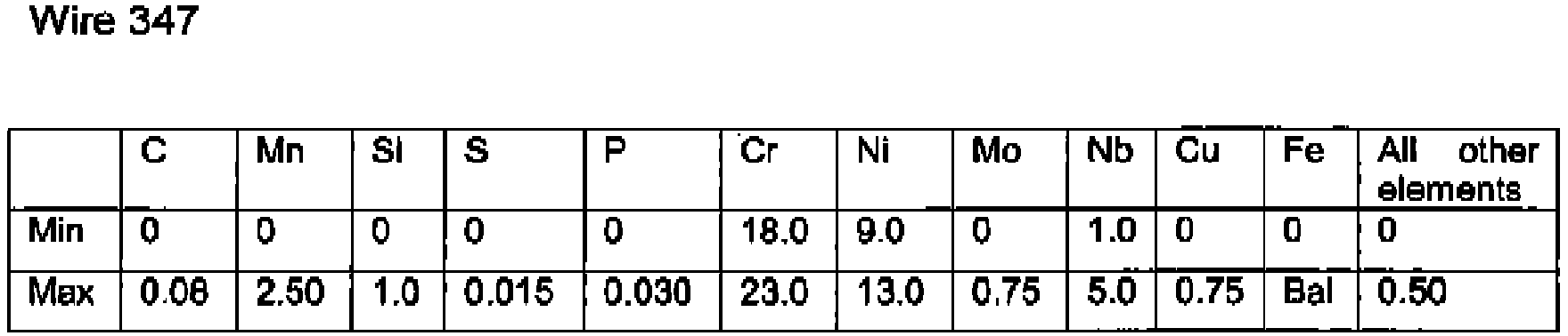
- In the Stainless Steel Base aspect, the invention uses a Ni-Cr stainless steel base sheath and a metal powder flux within the stainless steel base sheath, wherein the wire has a composition of WIRE 308L, WIRE 347, WIRE 316L, or WIRE 317L, as specified in the tables hereinbelow.
- The upper limit of at least one of the elements or of all elements may be 5%, 10% or 20% lower than specified in the corresponding table. The lower limit of at least one of the elements or of all elements may be 5%, 10% or 20% higher than specified In the corresponding table.
- The metal cored hybrid cladding wire is used for electroslag cladding of carbon/low alloy black steel together with a strip electrode, and preferably electroslag powder flux. The strip electrode and the flux may be of ordinary composition as the chemistry of the cladding layer is controlled by the wire, in the stainless steel aspect of the invention. It is not required to provide different strip electrodes or fluxes for the specific process, base material or desired weld overlay grade.
- The invention is suitable for a cladding system comprising a cladding head and a cladding power supply, the cladding head guiding a strip electrode onto a surface of a workpiece to be cladded with the strip electrode, the cladding power supply providing power to the strip electrode for arcless deposition onto the surface of the workpiece, the cladding head guiding a metal cored hybrid cladding wire Into the weld puddle of the strip electrode, the system further preferably comprising a flux feeder for deposition of flux on the strip electrode. The cladding system is hybrid in that it deposits a metal cored hybrid cladding wire into the puddle of a strip electrode for control of the chemistry of the cladding layer.
- The cladding system may comprise a hot wire power supply for heating the metal cored hybrid electroslag cladding wire, and/or a controller, preferably a programmable logic controller, for controlling at least one of the following parameters: the heat of the metal cored hybrid electroslag cladding wire according to a desired deposition rate, the stickout length of the strip and/or metal cored hybrid electroslag cladding wire, the feed speed of the strip electrode, the feed speed of the metal cored hybrid electroslag cladding wire.
- Preferably, the cladding system comprises a hot wire power supply for heating the metal cored hybrid cladding wire, and a controller for controlling the heat of the metal cored hybrid cladding wire according to a desired deposition rate.
- The cladding system may additionally comprise a magnet steering device adjacent the strip electrode for steering the weld puddle magnetically.
- The angle between the strip electrode and/or the metal cored hybrid cladding wire and the surface of the workpiece may be adjustable.
- The cladding head guides one, two, three or more adjacent metal cored hybrid cladding wires into the weld puddle. The wires are preferably identical or at least of equal diameter and spaced such that they cover the width of the strip electrode.
- Further features and embodiments of the invention are inferable from the ensuing description, drawings and claims.
-
-
Fig. 1 Illustrates a hybrid cladding system for use by the method according to the invention. -
Fig. 2 shows a cladding head in (a) a 3D-view, (b) a left view, (c) a front view, (d) a right view, (e) a rear view, and (f) an enlarged detail from the encircled region ofFig. 2(a) . -
Fig. 3 (a), (b), (c) illustrate variants with one, two and four metal cored hybrid cladding wires, in a view along the arrow 11 A ofFig. 1 . - Embodiments of the inventive method as well as systems and wires suitable for use therewith are discussed In more detail.
-
Fig. 1 illustrates acladding system 1 having a flux feeder 2 and acladding head 3 which guides both, astrip electrode 4 powered by acladding power supply 5 onto a surface of aworkpiece 6, as well as a metal coredhybrid cladding wire 7 heated by a hotwire power supply 8 into theweld puddle 9 of thestrip electrode 4. - The
strip electrode 4 covered byflux 10 is deposited onto the surface of theworkpiece 6 by means of an arcless electroslag process for cladding theworkpiece 6 while thecladding 3 head moves along theworkpiece 6 in the direction ofarrow 11. Both thestrip electrode 4 and the surface of theworkpiece 6 melt and form theweld puddle 9 which solidifies after a period of time. Prior to solidification, the metal coredhybrid cladding wire 7 is fed Into theweld puddle 9. Thewire 7 melts and mixes with theweld puddle 9, controlling the chemical composition of the resultingcladding layer 12. - A
controller 13 for controlling the heat of the metal coredhybrid cladding wire 7 according to a desired deposition rate, the movement of thecladding head 3, and thecladding power supply 5, is preferably provided. Thecontroller 13 may be connected to the powers supplies 5, 8 and thewelding head 3 as well as strip and wire feeders (not depicted) by wire connection, via a network and/or wirelessly. - The flux feeder 2 is preferably attached to the
cladding head 3 and filled with flux for electroslag cladding, seeFig. 2 showing an embodiment with two metal coredhybrid cladding wires 7. - In a preferred embodiment, the
cladding head 3 is adapted to guide thestrip electrode 4 about vertically onto the surface of theworkpiece 6, see In particularFig. 2(d) , and the metal coredhybrid cladding wire 7 is guided downstream ofmovement arrow 11 into the weld puddle. - A
magnetic steering device 14, here comprising two steeringmagnets 15 adjacent either side of thestrip electrode 4, may be provided for steering the weld puddle magnetically. This allows a precise control of the weld puddle, in particular width. -
Mechanisms 16 may be provided on the cladding head for adjustment the angle between thestrip electrode 4, the metal coredhybrid cladding wire 7, and/or the surface of theworkpiece 6, see in particularFig. 2 (d) . - A
strip wire feeder 17 and a metal cored hybridcladding wire feeder 18 are preferably attached on or provided adjacent the cladding head. - The
wire 7 is preferably positioned at the centre of the strip electrode, seeFig. 3(a) . More than onewire 7 can be used, seeFigs. 3(b), 3(c) . Ifmore wires 7 are used, they are preferably identical. However, they may be of different compositions and/or diameters. Ideally, thewires 7 are spaced equidistant across the width of thestrip electrode 4 in order to ensure a homogeneous composition of thecladding layer 12, however, they may also be spaced at different distances, e.g. closer towards the edges, seeFig. 3(c) , or centered as inFig. 2(c) . - In the stainless steel based aspect of the Invention, the following metal cored hybrid electroslag cladding wires are used (all figures are wt%, bal=balance):



- In the nickel based aspect of the invention, the following metal cored hybrid electroslag cladding wires are used (all figures are wt%):


Wire 400 C Mn Si S P Ni Cu Al Ti Fe Min 0 0 0 0 0 62.0 28.0 0 0 0 Max 0,15 4.0 1.2 0.015 0.020 68.0 36.0 0.75 1.2 2.5 All other elements <0.50% - The cladding system is operated according to the following method. First, a workpiece to be cladded is provided. Then, a strip electrode Is guided onto the surface of the workpiece. The strip electrode is cladded onto the surface of the workpiece using electroslag cladding, while a metal cored hybrid cladding wire is heated and guided into the weld puddle of the strip electrode.
- When cladding nickel based workpieces, a combination of a strip electrode and metal cored hybrid electroslag cladding wire is used to obtain the desired final chemistry of the cladding. When cladding stainless steel based workpieces, a standard strip electrode can be used for different workpiece compositions, and only the metal cored hybrid electroslag cladding wire will be varied to achieve the desired cladding composition. Preferred wire compositions are specified in the preceding section.
- It is preferred to make the following combinations:
Nickel Base metal cored hybrid electroslag cladding wire strip electrode Flux Alloy 625 Wire 625 Typical 625 Strip Flux A Alloy 600 Wire 600 Typical 600 Strip Flux A Alloy 825 Wire 825 Typical 825 Strip Flux A Alloy 400 Wire 400 Typical 400 Strip Flux A - The preferred Flux A is an Electro Slag High speed flux with Al2O3 + CaF2 >73wt % without any intended metallic addition. Other flux compositions may work as well, but with inferior performance. The strip Is preferably a standard strip.
Stainless Steel Base metal cored hybrid electroslag cladding wire strip electrode Flux 308L Wire 308L Typical 18Cr-8Ni Strip Flux B 347 Wire 347 Typical 18Cr-8Ni Strip Flux B 316L Wire 316L Typical 18Cr-8Ni Strip Flux B 317L Wire 317L Typical 18Cr-8Ni Strip Flux B - The preferred Flux B Is an Electro Slag High speed flux with Al2O3 + CaF2 >81wt % without any Intended metallic addition. Other flux compositions may work as well, but with inferior performance. The strip is preferably a typical 18Cr-8Ni Strip.
- The speed of movement of the
cladding head 3 is preferably about 27 cm/min, the cladding layer thickness is preferably about 5 mm. - Various different embodiments and individual aspects of the invention have been described above. They may be combined In any way. In a preferred embodiment, the invention provides a cladding head In which the strip electrode is fed essentially vertically onto the workplace and the metal cored hybrid wire Is fed In an adjustable angle relative thereto as indicated In
fig. 2 . A magnetic steering device Is provided In the preferred embodiment as are a PLC controller, configured to control stick out length of the strip and/or metal cored hybrid electroslag wire(s) and the feed speeds of the metal cored hybrid electroslag wire(s) and the strip electrode, as well as the heat provided to the metal cored hybrid electroslag wire(s). In the preferred embodiment, a single layer of cladding Is deposited on the workpiece with a high speed and homogenous and uniform cladding chemistry according to the required grade. - Although only a few embodiments of this invention have been described above, it should be appreciated that many modifications can be made without departing from the scope of the invention. All such modifications are intended to be included within the scope of this Invention, which is to be limited only by the following claims.
-
- 1
- hybrid electroslag cladding system
- 2
- flux feeder
- 3
- cladding head
- 4
- strip electrode
- 5
- cladding power supply
- 6
- workpiece
- 7
- metal cored hybrid electroslag cladding wire
- 8
- hot wire power supply
- 9
- weld puddle
- 10
- flux
- 11
- arrow
- 12
- cladding layer
- 13
- controller
- 14
- magnetic steering device
- 15
- steering magnet
- 16
- metal cored wire feeding mechanism
- 17
- strip wire feeder
- 18
- metal cored hybrid electroslag cladding wire feeder
Claims (15)
- Hybrid electroslag cladding method, comprising:providing a workpiece (6) to be cladded;guiding a strip electrode (4) onto the surface of the workpiece (6);cladding the strip electrode (4) onto the surface of the workpiece (6) using electroslag cladding;guiding a metal cored hybrid electroslag cladding wire (7) into the weld puddle (9) of the strip electrode (4) for controlling the chemical composition of the cladding;characterized byusing a strip electrode (4) with a given chemical composition for a first and a second workpiece (6) requiring stainless steel claddings with different cladding compositions, and selecting a first metal cored hybrid electroslag cladding wire (7) for controlling the chemical composition of the cladding of the first workpice (6) and a second metal cored hybrid electroslag cladding wire (7) for controlling the chemical composition of the cladding of the second workpiece (6), the first metal cored hybrid electroslag cladding wire (7) having a chemical composition that differs from the chemical composition of the second metal cored hybrid electroslag cladding wire (7).
- Method according to claim 1, characterized by using a flux of a given composition for a first and a second workpiece (6), the first workpiece (6) having a chemical composition that differs from the chemical composition of the second workpiece (6).
- Method according to claim 1 or 2, characterized by controlling at least one of the following parameters using a controller, in particular a programmable logic controller, and sensors: the stickout length of the metal cored electroslag cladding wire (7), the feed speed of the strip electrode (4), the feed speed of the metal cored electroslag cladding wire (7).
- Method of claim 3, characterized by changing the feed speed of the metal cored electroslag cladding wire (7) if a change of the feed speed of the strip electrode (4) is detected.
- Method according to one of the claims 1 to 4, wherein the metal cored electroslag cladding wire (7) is heated.
- Method according to one of the claims 1 to 5, characterized by using a metal cored electroslag cladding wire (7) having a Ni-Cr nickel base sheath and a metal powder flux within the Ni-Cr nickel base sheath, wherein the wire has a composition of: 0 ≤ C ≤ 0.05 wt%, 0 ≤ Mn ≤ 0.50 wt%, 0 ≤ Si ≤ 0.50 wt%, 0 ≤ S ≤ 0.015 wt%, 0 ≤ P ≤ 0.015 wt%, 22.0 ≤ Cr ≤ 27.0 wt%, 50 ≤ Ni wt%, 8.0 ≤ Mo ≤ 14.0 wt%, 3.5 ≤ Nb ≤ 6.5 wt%, 0 ≤ Cu ≤ 0.50 wt%, 0 ≤ Al ≤ 0.50 wt%, 0 ≤ Ti ≤ 0.50 wt%, 0 ≤ Fe ≤ 2.0 wt%.
- Method according to one of the claims 1 to 5, characterized by using a metal cored electroslag cladding wire (7) having a Ni-Cr nickel base sheath and a metal powder flux within the Ni-Cr nickel base sheath, wherein the wire has a composition of: 0 ≤ C ≤ 0.05 wt%, 2.0 ≤ Mn ≤ 5.0 wt%, 0 ≤ Si ≤ 0.50 wt%, 0 ≤ S ≤ 0.015 wt%, 0 ≤ P ≤ 0.020 wt%, 21.0 ≤ Cr ≤ 26.0 wt%, 67 ≤ Ni wt%, 2.0 ≤ Nb ≤ 5.0 wt%, 0 ≤ Cu ≤ 0.50 wt%, 0.2 ≤ Ti ≤ 0,8 wt%, 0 ≤ Fe ≤ 3.0 wt%.
- Method according to one of the claims 1 to 5, characterized by using a metal cored electroslag cladding wire (7) having a Ni-Cr nickel base sheath and a metal powder flux within the Ni-Cr nickel base sheath, wherein the wire has a composition of: 0 ≤C ≤ 0.05 wt%, 0 ≤ Mn ≤ 1.0 wt%, 0 ≤ Si ≤ 0.50 wt%, 0 ≤ S ≤ 0.015 wt%, 0 ≤ P ≤ 0.020 wt%, 24.0 ≤ Cr ≤ 27.0 wt%, 46 ≤ Ni ≤ 52 wt%, 2.0 ≤ Mo ≤ 14.0 wt%, 1.0 ≤ Cu ≤ 4.0 wt%, 0 ≤ Al ≤ 0.20 wt%, 0.8 ≤ Ti ≤ 1.6 wt%, 0 wt% ≤Fe.
- Method according to one of the claims 1 to 5, characterized by using a metal cored electroslag cladding wire (7) having a Ni-Cr nickel base sheath and a metal powder flux within the Ni-Cr nickel base sheath, wherein the wire has a composition of: 0 ≤ C ≤ 0.15 wt%, 0 ≤ Mn ≤ 4.0 wt%, 0 ≤ Si ≤ 1.2 wt%, 0 ≤ S ≤ 0.015 wt%, 0 ≤ P ≤ 0.020 wt%, 62.0 ≤ Ni ≤ 68.0 wt%, 28.0 ≤ Cu ≤ 36.0 wt%, 0 ≤ Al ≤ 0.75 wt%, 0 ≤ Ti ≤ 1.2 wt%, 0 ≤ Fe ≤ 2.5 wt%.
- Method according to one of the claims 1 to 5, characterized by using a metal cored electroslag cladding wire (7) having a stainless steel base sheath and a metal powder flux within the stainless steel base sheath, wherein the wire has a composition of: 0 ≤ C ≤ 0.03 wt%, 0.5 ≤ Mn < 2.50 wt%, 0 ≤ Si ≤ 1.0 wt%, 0 ≤ S ≤ 0.015 wt%, 0 ≤ P ≤ 0.030 wt%, 18.0 ≤ Cr ≤ 23.0 wt%, 9.0 ≤ Ni ≤ 13.0 wt%, 0 ≤ Mo ≤ 0.85 wt%, 0 ≤ Cu ≤ 0.75 wt%, 0 wt% ≤ Fe.
- Method according to one of the claims 1 to 5, characterized by using a metal cored electroslag cladding wire (7) having a stainless steel base sheath and a metal powder flux within the stainless steel base sheath, wherein the wire has a composition of: 0 ≤ C ≤ 0.08 wt%, 0 ≤ Mn ≤ 2.50 wt%, 0 ≤ Si ≤ 1.0 wt%, 0 ≤ S ≤ 0.015 wt%, 0 ≤ P ≤ 0.030 wt%, 18.0 ≤ Cr ≤ 23.0 wt%, 9.0 ≤ Ni ≤ 13.0 wt%, 0 ≤ Mo ≤ 0.75 wt%, 1.0 ≤ Nb ≤ 5.0 wt%, 0 ≤ Cu ≤ 0.75 wt%, 0 wt% ≤ Fe.
- Method according to one of the claims 1 to 5, characterized by using a metal cored electroslag cladding wire (7) having a stainless steel base sheath and a metal powder flux within the stainless steel base sheath, wherein the wire has a composition of: 0 ≤ C ≤ 0.04 wt%, 0 ≤ Mn ≤ 2.50 wt%, 0 ≤ Si ≤ 1.0 wt%, 0 ≤ S ≤ 0.015 wt%, 0 ≤ P ≤ 0.030 wt%, 17.0 ≤ Cr ≤ 22.0 wt%, 16 ≤ Ni ≤ 21.0 wt%, 7.0 ≤ Mo ≤ 11.0 wt%, 0 ≤ Cu ≤ 0.75 wt%, 0 wt% ≤ Fe.
- Method according to one of the claims 1 to 5, characterized by using a metal cored electroslag cladding wire (7) having a stainless steel base sheath and a metal powder flux within the stainless steel base sheath, wherein the wire has a composition of: 0 ≤ C ≤ 0.04 wt%, 0 ≤ Mn ≤ 2.50 wt%, 0 ≤ Si ≤ 1.0 wt%, 0 ≤ S ≤ 0.015 wt%, 0 ≤ P ≤ 0.030 wt%, 18.0 ≤ Cr ≤ 23.0 wt%, 18 ≤ Ni ≤ 22.0 wt%, 10.0 ≤ Mo ≤ 15.0 wt%, 0 ≤ Cu ≤ 0.75 wt%, 0 wt% ≤ Fe.
- Method according to one of the claims 6 to 13, wherein the upper limit of at least one of the elements or of all elements is 5%, 10% or 20% lower than specified in the composition.
- Method according to one of the claims 6 to 14, wherein the lower limit of at least one of the elements or of all elements is 5%, 10% or 20% higher than specified in the composition.
Priority Applications (2)
| Application Number | Priority Date | Filing Date | Title |
|---|---|---|---|
| PL15825945T PL3188873T3 (en) | 2015-06-19 | 2015-11-26 | Electroslag cladding method |
| EP20150575.7A EP3670061A1 (en) | 2015-06-19 | 2015-11-26 | Hybrid electroslag cladding |
Applications Claiming Priority (3)
| Application Number | Priority Date | Filing Date | Title |
|---|---|---|---|
| DE202015004355 | 2015-06-19 | ||
| DE202015007709.9U DE202015007709U1 (en) | 2015-06-19 | 2015-11-10 | Hybrid Electro-Slag |
| PCT/IB2015/002224 WO2016203286A1 (en) | 2015-06-19 | 2015-11-26 | Hybrid electroslag cladding |
Related Child Applications (1)
| Application Number | Title | Priority Date | Filing Date |
|---|---|---|---|
| EP20150575.7A Division EP3670061A1 (en) | 2015-06-19 | 2015-11-26 | Hybrid electroslag cladding |
Publications (2)
| Publication Number | Publication Date |
|---|---|
| EP3188873A1 EP3188873A1 (en) | 2017-07-12 |
| EP3188873B1 true EP3188873B1 (en) | 2020-01-08 |
Family
ID=57110211
Family Applications (2)
| Application Number | Title | Priority Date | Filing Date |
|---|---|---|---|
| EP15825945.7A Active EP3188873B1 (en) | 2015-06-19 | 2015-11-26 | Electroslag cladding method |
| EP20150575.7A Pending EP3670061A1 (en) | 2015-06-19 | 2015-11-26 | Hybrid electroslag cladding |
Family Applications After (1)
| Application Number | Title | Priority Date | Filing Date |
|---|---|---|---|
| EP20150575.7A Pending EP3670061A1 (en) | 2015-06-19 | 2015-11-26 | Hybrid electroslag cladding |
Country Status (8)
| Country | Link |
|---|---|
| US (1) | US10766100B2 (en) |
| EP (2) | EP3188873B1 (en) |
| JP (1) | JP2018517565A (en) |
| KR (1) | KR102110024B1 (en) |
| CN (1) | CN107771111B (en) |
| DE (1) | DE202015007709U1 (en) |
| PL (1) | PL3188873T3 (en) |
| WO (1) | WO2016203286A1 (en) |
Families Citing this family (10)
| Publication number | Priority date | Publication date | Assignee | Title |
|---|---|---|---|---|
| ITUA20162981A1 (en) | 2016-04-28 | 2017-10-28 | Illinois Tool Works | RELEASE DEVICES FOR A GRANULAR WELDING FLOW AND TAPE PLATING SYSTEMS WITH RELEASE DEVICES FOR A GRANULAR FLOW |
| ITUA20162979A1 (en) | 2016-04-28 | 2017-10-28 | Illinois Tool Works | HEADS FOR RIBBON PLATING WITH RIBBON PRESSURE LIMITS AND RIBBON BANDING SYSTEMS WITH HEADS FOR RIBBON BANDING WITH RIBBON PRESSURE LIMITS |
| ITUA20162983A1 (en) | 2016-04-28 | 2017-10-28 | Illinois Tool Works | HEADS FOR RIBBON PLATING HAVING INDEPENDENT BELT PRESSURE ADJUSTMENTS AND RIBBON BANDING SYSTEMS WITH HEADS FOR RIBBON BANDING WITH INDEPENDENT BELT PRESSURE ADJUSTMENT |
| ITUA20162977A1 (en) | 2016-04-28 | 2017-10-28 | Illinois Tool Works | TAPE FEEDERS FOR PLATING HAVING ADJUSTABLE RIBBON GUIDES AND RIBBON PLATING SYSTEMS WITH TAPE FEEDERS FOR PLATING HAVING ADJUSTABLE RIBBON GUIDES FOR THE RIBBON |
| ITUA20162975A1 (en) | 2016-04-28 | 2017-10-28 | Illinois Tool Works | TAPE FEEDERS FOR PLATING HAVING INDEPENDENT PRESSURE ROLLERS AND TAPE PLATING SYSTEMS WITH TAPE FEEDERS FOR PLATING HAVING INDEPENDENT PRESSURE ROLLERS |
| US11801569B2 (en) * | 2017-06-28 | 2023-10-31 | Esab Ab | Stopping an electroslag welding process |
| BE1027743B1 (en) * | 2020-04-02 | 2021-06-08 | Voestalpine Boehler Welding Belgium | PROCESS FOR DEPOSITING A COVERING MATERIAL IN AT LEAST TWO LAYERS ON A METAL SURFACE BY MEANS OF A VENEER WITH STRIP BY FUSION IN ELECTRIC CONDUCTIVE MILK |
| US12358066B2 (en) | 2021-12-13 | 2025-07-15 | Esab Ab | Dual twin-saw wire cladding |
| CN115635092B (en) * | 2022-11-04 | 2026-05-12 | 北京航空航天大学 | Method and device for preparing ultrafine powder by taking strip as pulse discharge electrode |
| CN116038099A (en) * | 2022-12-13 | 2023-05-02 | 永胜机械工业(昆山)有限公司 | A new urea grade super austenitic stainless steel electroslag surfacing process |
Family Cites Families (14)
| Publication number | Priority date | Publication date | Assignee | Title |
|---|---|---|---|---|
| JPS508749A (en) * | 1973-05-29 | 1975-01-29 | ||
| JPS5785686A (en) * | 1980-11-19 | 1982-05-28 | Kawasaki Steel Corp | Horizontal electroslag alloy build-up welding method |
| SE433579B (en) * | 1983-08-22 | 1984-06-04 | Sitnikov Ivan I | ELECTRICAL WELDING AND PASSWELDING DEVICE |
| KR100739513B1 (en) * | 1999-06-10 | 2007-07-13 | 인코 앨로이즈 인터내셔날, 인코포레이티드 | Welding alloy and welding product, welding material and manufacturing method of welding material |
| DE102007006688B4 (en) | 2007-02-10 | 2011-10-27 | Eisenbau Krämer mbH | Welding process and its application |
| CN100551603C (en) * | 2007-04-28 | 2009-10-21 | 重庆大学 | An Electromagnetic Composite Field Fusion Pole Surfacing Method, Equipment and Its Extended Application |
| US9289843B2 (en) * | 2011-07-01 | 2016-03-22 | Lincoln Global, Inc. | Tandem strip cladding method and apparatus |
| TWI604912B (en) | 2011-07-13 | 2017-11-11 | Illinois Tool Works | Cored welding wires, the method for making the same and its use |
| US10105780B2 (en) * | 2012-07-06 | 2018-10-23 | Lincoln Global, Inc. | Method and system of using a consumable and a heat source with a weld puddle |
| BR112015003409B1 (en) * | 2012-08-14 | 2018-12-04 | Esab Ab | method and system for submerged arc welding |
| US9272363B2 (en) * | 2013-01-31 | 2016-03-01 | Siemens Energy, Inc. | Hybrid laser plus submerged arc or electroslag cladding of superalloys |
| JP5968855B2 (en) | 2013-10-31 | 2016-08-10 | 株式会社神戸製鋼所 | Ni-based alloy flux cored wire |
| CN104668767A (en) * | 2013-12-03 | 2015-06-03 | 黑龙江融德建筑技术开发有限公司 | Tubular dissolved nozzle electroslag welding device of steel structural high-rise building construction |
| US10046419B2 (en) * | 2014-01-24 | 2018-08-14 | Lincoln Global, Inc. | Method and system for additive manufacturing using high energy source and hot-wire |
-
2015
- 2015-11-10 DE DE202015007709.9U patent/DE202015007709U1/en not_active Expired - Lifetime
- 2015-11-26 EP EP15825945.7A patent/EP3188873B1/en active Active
- 2015-11-26 JP JP2017565784A patent/JP2018517565A/en active Pending
- 2015-11-26 PL PL15825945T patent/PL3188873T3/en unknown
- 2015-11-26 KR KR1020177037022A patent/KR102110024B1/en active Active
- 2015-11-26 EP EP20150575.7A patent/EP3670061A1/en active Pending
- 2015-11-26 US US15/737,689 patent/US10766100B2/en active Active
- 2015-11-26 WO PCT/IB2015/002224 patent/WO2016203286A1/en not_active Ceased
- 2015-11-26 CN CN201580081120.1A patent/CN107771111B/en active Active
Non-Patent Citations (1)
| Title |
|---|
| None * |
Also Published As
| Publication number | Publication date |
|---|---|
| JP2018517565A (en) | 2018-07-05 |
| EP3670061A1 (en) | 2020-06-24 |
| WO2016203286A1 (en) | 2016-12-22 |
| CN107771111B (en) | 2020-03-20 |
| CN107771111A (en) | 2018-03-06 |
| KR102110024B1 (en) | 2020-05-13 |
| PL3188873T3 (en) | 2020-07-27 |
| US10766100B2 (en) | 2020-09-08 |
| KR20180018583A (en) | 2018-02-21 |
| DE202015007709U1 (en) | 2016-09-21 |
| EP3188873A1 (en) | 2017-07-12 |
| US20180178317A1 (en) | 2018-06-28 |
Similar Documents
| Publication | Publication Date | Title |
|---|---|---|
| EP3670061A1 (en) | Hybrid electroslag cladding | |
| JP4676698B2 (en) | Improved consumable electrode arc welding | |
| JP5792712B2 (en) | Welding head and welding head assembly for an arc welding system | |
| US20160199939A1 (en) | Hot wire laser cladding process and consumables used for the same | |
| EP2879833B1 (en) | Root pass welding | |
| EP2885106B1 (en) | Method and system for submerged arc welding | |
| DE212013000148U1 (en) | A system for using induction heating to heat a consumable during a hot wire process | |
| GB1586103A (en) | Method of connecting metallic parts by means including arc fusion welding | |
| CA3036375C (en) | Helical welding wire and helix forming welding torch | |
| JP2018517565A5 (en) | ||
| EP1762324B2 (en) | Flux system to reduce copper cracking | |
| KR101172016B1 (en) | Weld wire and process for manufacturing the weld wire | |
| US5945014A (en) | Method of arc welding heavy steel plates | |
| JPH0675792B2 (en) | Plasma arc welding method | |
| EP1677939B1 (en) | Manufacture of thin hardfaced plates | |
| KR102228164B1 (en) | Adaptive Control Method with changing groove width | |
| KR101931140B1 (en) | Method of depositing an overlay material onto a metal surface by means of electroslag strip cladding, with flux having more than 55 wt% caf2; corresponding flux and article with such overlay | |
| EP1147844B1 (en) | Method of plasma powder brazing | |
| EP3799991A1 (en) | A system and a method achieving ultra high deposition rate welding | |
| EP1570939B1 (en) | Submerged arc welding process | |
| JP3726813B2 (en) | Powder plasma welding apparatus and welding method | |
| JP5979734B2 (en) | Welding head and welding head assembly for an arc welding system | |
| KR20140023765A (en) | Multilayer electro gas arc welding and welded material thereof | |
| JP6637272B2 (en) | Welding method |
Legal Events
| Date | Code | Title | Description |
|---|---|---|---|
| STAA | Information on the status of an ep patent application or granted ep patent |
Free format text: STATUS: UNKNOWN |
|
| STAA | Information on the status of an ep patent application or granted ep patent |
Free format text: STATUS: THE INTERNATIONAL PUBLICATION HAS BEEN MADE |
|
| PUAI | Public reference made under article 153(3) epc to a published international application that has entered the european phase |
Free format text: ORIGINAL CODE: 0009012 |
|
| STAA | Information on the status of an ep patent application or granted ep patent |
Free format text: STATUS: REQUEST FOR EXAMINATION WAS MADE |
|
| 17P | Request for examination filed |
Effective date: 20170406 |
|
| AK | Designated contracting states |
Kind code of ref document: A1 Designated state(s): AL AT BE BG CH CY CZ DE DK EE ES FI FR GB GR HR HU IE IS IT LI LT LU LV MC MK MT NL NO PL PT RO RS SE SI SK SM TR |
|
| AX | Request for extension of the european patent |
Extension state: BA ME |
|
| STAA | Information on the status of an ep patent application or granted ep patent |
Free format text: STATUS: EXAMINATION IS IN PROGRESS |
|
| 17Q | First examination report despatched |
Effective date: 20180404 |
|
| DAV | Request for validation of the european patent (deleted) | ||
| DAX | Request for extension of the european patent (deleted) | ||
| GRAP | Despatch of communication of intention to grant a patent |
Free format text: ORIGINAL CODE: EPIDOSNIGR1 |
|
| STAA | Information on the status of an ep patent application or granted ep patent |
Free format text: STATUS: GRANT OF PATENT IS INTENDED |
|
| INTG | Intention to grant announced |
Effective date: 20190705 |
|
| GRAS | Grant fee paid |
Free format text: ORIGINAL CODE: EPIDOSNIGR3 |
|
| GRAA | (expected) grant |
Free format text: ORIGINAL CODE: 0009210 |
|
| STAA | Information on the status of an ep patent application or granted ep patent |
Free format text: STATUS: THE PATENT HAS BEEN GRANTED |
|
| RIN1 | Information on inventor provided before grant (corrected) |
Inventor name: THUME, CHRISTOPHER Inventor name: NATHEGHI, AMIN Inventor name: GOLDING, MARK, S. Inventor name: CHATTOPADHYAY, PALLAV Inventor name: POLLMANN, ROLAND Inventor name: BOLTE, FRANK Inventor name: ZHANG, ZHUYAO |
|
| AK | Designated contracting states |
Kind code of ref document: B1 Designated state(s): AL AT BE BG CH CY CZ DE DK EE ES FI FR GB GR HR HU IE IS IT LI LT LU LV MC MK MT NL NO PL PT RO RS SE SI SK SM TR |
|
| REG | Reference to a national code |
Ref country code: GB Ref legal event code: FG4D |
|
| REG | Reference to a national code |
Ref country code: CH Ref legal event code: EP |
|
| REG | Reference to a national code |
Ref country code: DE Ref legal event code: R096 Ref document number: 602015045316 Country of ref document: DE |
|
| REG | Reference to a national code |
Ref country code: IE Ref legal event code: FG4D |
|
| REG | Reference to a national code |
Ref country code: AT Ref legal event code: REF Ref document number: 1222095 Country of ref document: AT Kind code of ref document: T Effective date: 20200215 |
|
| REG | Reference to a national code |
Ref country code: SE Ref legal event code: TRGR |
|
| REG | Reference to a national code |
Ref country code: NL Ref legal event code: MP Effective date: 20200108 |
|
| REG | Reference to a national code |
Ref country code: LT Ref legal event code: MG4D |
|
| PG25 | Lapsed in a contracting state [announced via postgrant information from national office to epo] |
Ref country code: FI Free format text: LAPSE BECAUSE OF FAILURE TO SUBMIT A TRANSLATION OF THE DESCRIPTION OR TO PAY THE FEE WITHIN THE PRESCRIBED TIME-LIMIT Effective date: 20200108 Ref country code: NO Free format text: LAPSE BECAUSE OF FAILURE TO SUBMIT A TRANSLATION OF THE DESCRIPTION OR TO PAY THE FEE WITHIN THE PRESCRIBED TIME-LIMIT Effective date: 20200408 Ref country code: LT Free format text: LAPSE BECAUSE OF FAILURE TO SUBMIT A TRANSLATION OF THE DESCRIPTION OR TO PAY THE FEE WITHIN THE PRESCRIBED TIME-LIMIT Effective date: 20200108 Ref country code: NL Free format text: LAPSE BECAUSE OF FAILURE TO SUBMIT A TRANSLATION OF THE DESCRIPTION OR TO PAY THE FEE WITHIN THE PRESCRIBED TIME-LIMIT Effective date: 20200108 Ref country code: PT Free format text: LAPSE BECAUSE OF FAILURE TO SUBMIT A TRANSLATION OF THE DESCRIPTION OR TO PAY THE FEE WITHIN THE PRESCRIBED TIME-LIMIT Effective date: 20200531 Ref country code: RS Free format text: LAPSE BECAUSE OF FAILURE TO SUBMIT A TRANSLATION OF THE DESCRIPTION OR TO PAY THE FEE WITHIN THE PRESCRIBED TIME-LIMIT Effective date: 20200108 |
|
| PG25 | Lapsed in a contracting state [announced via postgrant information from national office to epo] |
Ref country code: BG Free format text: LAPSE BECAUSE OF FAILURE TO SUBMIT A TRANSLATION OF THE DESCRIPTION OR TO PAY THE FEE WITHIN THE PRESCRIBED TIME-LIMIT Effective date: 20200408 Ref country code: GR Free format text: LAPSE BECAUSE OF FAILURE TO SUBMIT A TRANSLATION OF THE DESCRIPTION OR TO PAY THE FEE WITHIN THE PRESCRIBED TIME-LIMIT Effective date: 20200409 Ref country code: HR Free format text: LAPSE BECAUSE OF FAILURE TO SUBMIT A TRANSLATION OF THE DESCRIPTION OR TO PAY THE FEE WITHIN THE PRESCRIBED TIME-LIMIT Effective date: 20200108 Ref country code: IS Free format text: LAPSE BECAUSE OF FAILURE TO SUBMIT A TRANSLATION OF THE DESCRIPTION OR TO PAY THE FEE WITHIN THE PRESCRIBED TIME-LIMIT Effective date: 20200508 Ref country code: LV Free format text: LAPSE BECAUSE OF FAILURE TO SUBMIT A TRANSLATION OF THE DESCRIPTION OR TO PAY THE FEE WITHIN THE PRESCRIBED TIME-LIMIT Effective date: 20200108 |
|
| REG | Reference to a national code |
Ref country code: DE Ref legal event code: R097 Ref document number: 602015045316 Country of ref document: DE |
|
| REG | Reference to a national code |
Ref country code: AT Ref legal event code: UEP Ref document number: 1222095 Country of ref document: AT Kind code of ref document: T Effective date: 20200108 |
|
| PG25 | Lapsed in a contracting state [announced via postgrant information from national office to epo] |
Ref country code: ES Free format text: LAPSE BECAUSE OF FAILURE TO SUBMIT A TRANSLATION OF THE DESCRIPTION OR TO PAY THE FEE WITHIN THE PRESCRIBED TIME-LIMIT Effective date: 20200108 Ref country code: RO Free format text: LAPSE BECAUSE OF FAILURE TO SUBMIT A TRANSLATION OF THE DESCRIPTION OR TO PAY THE FEE WITHIN THE PRESCRIBED TIME-LIMIT Effective date: 20200108 Ref country code: DK Free format text: LAPSE BECAUSE OF FAILURE TO SUBMIT A TRANSLATION OF THE DESCRIPTION OR TO PAY THE FEE WITHIN THE PRESCRIBED TIME-LIMIT Effective date: 20200108 Ref country code: EE Free format text: LAPSE BECAUSE OF FAILURE TO SUBMIT A TRANSLATION OF THE DESCRIPTION OR TO PAY THE FEE WITHIN THE PRESCRIBED TIME-LIMIT Effective date: 20200108 Ref country code: SM Free format text: LAPSE BECAUSE OF FAILURE TO SUBMIT A TRANSLATION OF THE DESCRIPTION OR TO PAY THE FEE WITHIN THE PRESCRIBED TIME-LIMIT Effective date: 20200108 Ref country code: SK Free format text: LAPSE BECAUSE OF FAILURE TO SUBMIT A TRANSLATION OF THE DESCRIPTION OR TO PAY THE FEE WITHIN THE PRESCRIBED TIME-LIMIT Effective date: 20200108 |
|
| PLBE | No opposition filed within time limit |
Free format text: ORIGINAL CODE: 0009261 |
|
| STAA | Information on the status of an ep patent application or granted ep patent |
Free format text: STATUS: NO OPPOSITION FILED WITHIN TIME LIMIT |
|
| 26N | No opposition filed |
Effective date: 20201009 |
|
| PG25 | Lapsed in a contracting state [announced via postgrant information from national office to epo] |
Ref country code: IT Free format text: LAPSE BECAUSE OF FAILURE TO SUBMIT A TRANSLATION OF THE DESCRIPTION OR TO PAY THE FEE WITHIN THE PRESCRIBED TIME-LIMIT Effective date: 20200108 |
|
| PG25 | Lapsed in a contracting state [announced via postgrant information from national office to epo] |
Ref country code: SI Free format text: LAPSE BECAUSE OF FAILURE TO SUBMIT A TRANSLATION OF THE DESCRIPTION OR TO PAY THE FEE WITHIN THE PRESCRIBED TIME-LIMIT Effective date: 20200108 |
|
| PG25 | Lapsed in a contracting state [announced via postgrant information from national office to epo] |
Ref country code: MC Free format text: LAPSE BECAUSE OF FAILURE TO SUBMIT A TRANSLATION OF THE DESCRIPTION OR TO PAY THE FEE WITHIN THE PRESCRIBED TIME-LIMIT Effective date: 20200108 |
|
| REG | Reference to a national code |
Ref country code: CH Ref legal event code: PL |
|
| GBPC | Gb: european patent ceased through non-payment of renewal fee |
Effective date: 20201126 |
|
| PG25 | Lapsed in a contracting state [announced via postgrant information from national office to epo] |
Ref country code: LU Free format text: LAPSE BECAUSE OF NON-PAYMENT OF DUE FEES Effective date: 20201126 |
|
| REG | Reference to a national code |
Ref country code: BE Ref legal event code: MM Effective date: 20201130 |
|
| PG25 | Lapsed in a contracting state [announced via postgrant information from national office to epo] |
Ref country code: LI Free format text: LAPSE BECAUSE OF NON-PAYMENT OF DUE FEES Effective date: 20201130 Ref country code: CH Free format text: LAPSE BECAUSE OF NON-PAYMENT OF DUE FEES Effective date: 20201130 |
|
| PG25 | Lapsed in a contracting state [announced via postgrant information from national office to epo] |
Ref country code: FR Free format text: LAPSE BECAUSE OF NON-PAYMENT OF DUE FEES Effective date: 20201130 Ref country code: IE Free format text: LAPSE BECAUSE OF NON-PAYMENT OF DUE FEES Effective date: 20201126 |
|
| PG25 | Lapsed in a contracting state [announced via postgrant information from national office to epo] |
Ref country code: GB Free format text: LAPSE BECAUSE OF NON-PAYMENT OF DUE FEES Effective date: 20201126 |
|
| PGFP | Annual fee paid to national office [announced via postgrant information from national office to epo] |
Ref country code: PL Payment date: 20211118 Year of fee payment: 7 |
|
| PG25 | Lapsed in a contracting state [announced via postgrant information from national office to epo] |
Ref country code: TR Free format text: LAPSE BECAUSE OF FAILURE TO SUBMIT A TRANSLATION OF THE DESCRIPTION OR TO PAY THE FEE WITHIN THE PRESCRIBED TIME-LIMIT Effective date: 20200108 Ref country code: MT Free format text: LAPSE BECAUSE OF FAILURE TO SUBMIT A TRANSLATION OF THE DESCRIPTION OR TO PAY THE FEE WITHIN THE PRESCRIBED TIME-LIMIT Effective date: 20200108 Ref country code: CY Free format text: LAPSE BECAUSE OF FAILURE TO SUBMIT A TRANSLATION OF THE DESCRIPTION OR TO PAY THE FEE WITHIN THE PRESCRIBED TIME-LIMIT Effective date: 20200108 |
|
| PG25 | Lapsed in a contracting state [announced via postgrant information from national office to epo] |
Ref country code: MK Free format text: LAPSE BECAUSE OF FAILURE TO SUBMIT A TRANSLATION OF THE DESCRIPTION OR TO PAY THE FEE WITHIN THE PRESCRIBED TIME-LIMIT Effective date: 20200108 Ref country code: AL Free format text: LAPSE BECAUSE OF FAILURE TO SUBMIT A TRANSLATION OF THE DESCRIPTION OR TO PAY THE FEE WITHIN THE PRESCRIBED TIME-LIMIT Effective date: 20200108 |
|
| PG25 | Lapsed in a contracting state [announced via postgrant information from national office to epo] |
Ref country code: BE Free format text: LAPSE BECAUSE OF NON-PAYMENT OF DUE FEES Effective date: 20201130 |
|
| PG25 | Lapsed in a contracting state [announced via postgrant information from national office to epo] |
Ref country code: PL Free format text: LAPSE BECAUSE OF NON-PAYMENT OF DUE FEES Effective date: 20221126 |
|
| PG25 | Lapsed in a contracting state [announced via postgrant information from national office to epo] |
Ref country code: PL Free format text: LAPSE BECAUSE OF NON-PAYMENT OF DUE FEES Effective date: 20221126 |
|
| PGFP | Annual fee paid to national office [announced via postgrant information from national office to epo] |
Ref country code: DE Payment date: 20251118 Year of fee payment: 11 |
|
| PGFP | Annual fee paid to national office [announced via postgrant information from national office to epo] |
Ref country code: AT Payment date: 20251117 Year of fee payment: 11 |
|
| PGFP | Annual fee paid to national office [announced via postgrant information from national office to epo] |
Ref country code: SE Payment date: 20251119 Year of fee payment: 11 |
|
| PGFP | Annual fee paid to national office [announced via postgrant information from national office to epo] |
Ref country code: CZ Payment date: 20251113 Year of fee payment: 11 |