EP3188395A1 - Device and method for generating precoding matrix, and storage medium - Google Patents
Device and method for generating precoding matrix, and storage medium Download PDFInfo
- Publication number
- EP3188395A1 EP3188395A1 EP15844462.0A EP15844462A EP3188395A1 EP 3188395 A1 EP3188395 A1 EP 3188395A1 EP 15844462 A EP15844462 A EP 15844462A EP 3188395 A1 EP3188395 A1 EP 3188395A1
- Authority
- EP
- European Patent Office
- Prior art keywords
- precoding matrix
- parameter
- row
- lookup table
- generating
- Prior art date
- Legal status (The legal status is an assumption and is not a legal conclusion. Google has not performed a legal analysis and makes no representation as to the accuracy of the status listed.)
- Granted
Links
Images


Classifications
-
- H—ELECTRICITY
- H04—ELECTRIC COMMUNICATION TECHNIQUE
- H04B—TRANSMISSION
- H04B7/00—Radio transmission systems, i.e. using radiation field
- H04B7/02—Diversity systems; Multi-antenna system, i.e. transmission or reception using multiple antennas
- H04B7/04—Diversity systems; Multi-antenna system, i.e. transmission or reception using multiple antennas using two or more spaced independent antennas
- H04B7/0413—MIMO systems
- H04B7/0456—Selection of precoding matrices or codebooks, e.g. using matrices antenna weighting
-
- H—ELECTRICITY
- H04—ELECTRIC COMMUNICATION TECHNIQUE
- H04L—TRANSMISSION OF DIGITAL INFORMATION, e.g. TELEGRAPHIC COMMUNICATION
- H04L25/00—Baseband systems
- H04L25/02—Details ; arrangements for supplying electrical power along data transmission lines
- H04L25/03—Shaping networks in transmitter or receiver, e.g. adaptive shaping networks
- H04L25/03891—Spatial equalizers
- H04L25/03898—Spatial equalizers codebook-based design
- H04L25/0391—Spatial equalizers codebook-based design construction details of matrices
-
- H—ELECTRICITY
- H04—ELECTRIC COMMUNICATION TECHNIQUE
- H04B—TRANSMISSION
- H04B7/00—Radio transmission systems, i.e. using radiation field
- H04B7/02—Diversity systems; Multi-antenna system, i.e. transmission or reception using multiple antennas
- H04B7/04—Diversity systems; Multi-antenna system, i.e. transmission or reception using multiple antennas using two or more spaced independent antennas
- H04B7/0413—MIMO systems
- H04B7/0456—Selection of precoding matrices or codebooks, e.g. using matrices antenna weighting
- H04B7/0478—Special codebook structures directed to feedback optimisation
-
- H—ELECTRICITY
- H04—ELECTRIC COMMUNICATION TECHNIQUE
- H04B—TRANSMISSION
- H04B7/00—Radio transmission systems, i.e. using radiation field
- H04B7/02—Diversity systems; Multi-antenna system, i.e. transmission or reception using multiple antennas
- H04B7/04—Diversity systems; Multi-antenna system, i.e. transmission or reception using multiple antennas using two or more spaced independent antennas
- H04B7/06—Diversity systems; Multi-antenna system, i.e. transmission or reception using multiple antennas using two or more spaced independent antennas at the transmitting station
- H04B7/0613—Diversity systems; Multi-antenna system, i.e. transmission or reception using multiple antennas using two or more spaced independent antennas at the transmitting station using simultaneous transmission
- H04B7/0615—Diversity systems; Multi-antenna system, i.e. transmission or reception using multiple antennas using two or more spaced independent antennas at the transmitting station using simultaneous transmission of weighted versions of same signal
- H04B7/0619—Diversity systems; Multi-antenna system, i.e. transmission or reception using multiple antennas using two or more spaced independent antennas at the transmitting station using simultaneous transmission of weighted versions of same signal using feedback from receiving side
- H04B7/0636—Feedback format
- H04B7/0639—Using selective indices, e.g. of a codebook, e.g. pre-distortion matrix index [PMI] or for beam selection
Definitions
- the disclosure relates to the field of mobile communications, and in particular to a device and method for generating a precoding matrix, and a storage medium.
- MIMO Multiple-Input Multiple-Output
- the commonly used method for generating a precoding matrix is storing all possible precoding matrixes by providing a large storage device.
- the number of the precoding matrixes increases rapidly.
- storing all the precoding matrixes needs a very expensive storage device, causing the cost of the terminal to increase.
- the disclosure is intended to provide a device and method for generating a precoding matrix, and a storage medium in the embodiments, which can generate a precoding matrix through simple calculation and table lookup, thereby avoiding consuming a large number of storage units.
- a device for generating a precoding matrix which includes: a parameter calculator, a counter and an element generator.
- the parameter calculator is arranged to calculate, according to a first Precoding Matrix Identifier (PMI) and a second PMI, a first parameter and a second parameter for determining a precoding matrix, and send the first parameter and the second parameter to the element generator.
- PMI Precoding Matrix Identifier
- the counter is arranged to control a row number of an element in the precoding matrix that is to be generated by the element generator.
- the element generator is arranged to generate the element corresponding to the row number in the precoding matrix according to the received first parameter and second parameter and the row number.
- the element generator includes: a first lookup table unit, a second lookup table unit, a first lookup table address unit, and an element output control unit.
- the first lookup table unit is arranged to store values of elements from the zeroth row to the third row in the precoding matrix calculated in advance, and obtain, according to a base address input by the first lookup table address unit, a value of the corresponding element and output the value of the corresponding element.
- the second lookup table unit is arranged to store values of operator influencing elements from the fourth row to the seventh row in the precoding matrix calculated in advance, inquire the value of the operator according to the second parameter, calculate the product of the value of the element output by the first lookup table unit and the value of the operator, and send the product to the element output control unit as the value of the corresponding element from the fourth row to the seventh row in the precoding matrix.
- the first lookup table address unit is arranged to generate the base address of the first lookup table unit according to the first parameter and the row number, and send the base address to the first lookup table unit.
- the element output control unit is arranged to receive inputs of the first lookup table unit and the second lookup table unit, and output the element corresponding to the row number in the precoding matrix according to the row number input by the counter.
- the first lookup table address unit is implemented by a four-to-one multiplexer.
- the element output control unit is implemented by a two-to-one multiplexer.
- a method for generating a precoding matrix which includes the following steps: the first parameter and the second parameter for determining the precoding matrix are calculated according to the first PMI and the second PMI; a row number of an element in the precoding matrix is controlled by the counter; the element corresponding to the row number in the precoding matrix is generated in order according to the first parameter, the second parameter and the row number; and elements in the precoding matrix are output in an ascending order of row numbers.
- the method before the element corresponding to the row number in the precoding matrix are generated in order according to the first parameter, the second parameter and the row number, the method further includes the following steps: the values of the elements from the zeroth row to the third row in the precoding matrix are calculated in advance, and the corresponding relationships between the values of the elements and the first parameter are established, and the corresponding relationships are stored in the first lookup table; and the values of the operator influencing the elements from the fourth row to the seventh row in the precoding matrix calculated are calculated in advance, and corresponding relationships between the values of the operator and the second parameter are established, and the corresponding relationships are stored in the second lookup table.
- the base address of the first lookup table is generated according to the first parameter and the row number; a value of a first element is obtained from the first lookup table according to the base address; the values of the operator are obtained from the second lookup table according to the second parameter; when the row number is from the zeroth row to the third row, the value of the first element is output as the value of the element corresponding to the row number in the precoding matrix; and when the row number is from the fourth row to the seventh row, the product of the value of the first element and the value of the operator is calculated and output as the value corresponding to the row number in the precoding matrix.
- the base address of the first lookup table is generated according to the zeroth bit to the fourth bit of the first parameter and the zeroth bit to the first bit of the row number.
- the device and method for generating a precoding matrix, and the storage medium provided by the disclosure can generate the elements of a precoding matrix through simple calculation and table lookup and then generate the precoding matrix, thereby avoiding consuming a large number of storage units to store various precoding matrixes.
- the number of antennas of a base station communicating with an LET terminal is 1, so the number of layers of a precoding matrix for the LTE terminal to calculate a Channel Quality Indicator (CQI) is 1;
- W m , n 1 represents a precoding matrix determined by parameters m and n whose the number of layers is 1;
- Fig. 1 is a structure diagram of a device for generating a precoding matrix according to an embodiment of the disclosure; as shown in Fig. 1 , the device includes: a parameter calculator 101, a counter 102, and an element generator 103.
- the parameter calculator 101 is arranged to calculate, according to the first PMI and the second PMI, the first parameter m and the second parameter n for determining the precoding matrix W m , n 1 , and send the first parameter m and the second parameter n to the element generator 103.
- the counter 102 is arranged to control a row number of an element in the precoding matrix that are to be generated by the element generator 103.
- the element generator 103 is arranged to generate the element in a (valid_cnt)th row in the precoding matrix according to the received first parameter m, the second parameter n and a row number valid_cnt.
- I1 and I2 can be any integer in [0, 15], and in the practical application, they are 4-bit binary numbers.
- the counter 102 generates the row number of the element in the precoding matrix; the row number is marked as valid_cnt in a range is [0, 7], and in the practical application, it is a 3-bit binary number.
- the counter 102 sends the valid-cnt to the element generator 103, so as to control the element generator 103 to generate the element of which the row number is valid-cnt in the precoding matrix.
- the value of valid_cnt gradually increases from 0 to 7, so that the element generator 103 is controlled to gradually output the element in the zeroth row, the element in the first row ... until the element in the seventh row, thereby generating the whole 8 ⁇ 1 precoding matrix.
- the element generator 103 includes: a first lookup table unit 201, a second lookup table unit 202, a first lookup table address unit 203, and an element output control unit 204.
- the first lookup table address unit 203 is arranged to generate a base address of the first lookup table unit according to the first parameter m and the row number valid_cnt, and send the base address to the first lookup table unit 201; here, the first lookup table address unit 203 may be implemented by a four-to-one multiplexer.
- the first lookup table unit 201 is arranged to store values of elements from the zeroth row to the third row in the precoding matrix calculated in advance, and obtain, according to the base address input by the first lookup table address unit 203, a value of the corresponding element, and output the value of the corresponding element; here, the first lookup table unit 201 can be implemented by a Read-Only Memory (ROM) and an auxiliary circuit.
- ROM Read-Only Memory
- the second lookup table unit 202 is arranged to store values of an operator influencing elements from the fourth row to the seventh row in the precoding matrix calculated in advance, inquire a value of the operator according to the second parameter n, calculate the product of the value of the element output by the first lookup table unit 201 and the value of the operator, and send the product to the element output control unit 204 as the value of the corresponding element from the fourth row to the seventh row in the precoding matrix; here, the second lookup table unit 202 can be implemented by the ROM and the auxiliary circuit.
- the element output control unit 204 is arranged to receive inputs of the first lookup table unit 201 and the second lookup table unit 202, and output the (valid_cnt)th element in the precoding matrix according to the row number valid_cnt input by the counter 102; here, the element output control unit 204 can be implemented by a two-to-one multiplexer.
- the matrix M is equal to 1 8 v m , that is, the matrix M is only dependent on the first parameter m. Because the values of m are a limited set, 1 8 v m corresponding to all the m can be calculated in advance and stored in the first lookup table unit 201, so that the element Mi of the ith row in the matrix M can be obtained when ixm is taken as the base address to search the first lookup table unit 201, where 0 ⁇ i ⁇ 3, and i is an integer.
- ⁇ n corresponding to all the n can be calculated in advance and stored in the second lookup table unit 202, so that the values of the operator ⁇ n corresponding to the n can be obtained when the n is taken as the base address to search the second lookup table unit 202, and then the element Ni of the ith row in the matrix N is calculated; Ni is equal to ⁇ n Mi, and corresponds to the element of the (i+4)th row in the precoding matrix W m , n 1 .
- the first lookup table address unit 203 receives the 0-4 bits, namely m[4:0], of the first parameter m which is sent by the parameter calculator 101, and receives the 0-1 bits, namely valid_cnt[1:0], of the row number valid_cnt which is sent by the counter 102; the base address ixm of the first lookup table is obtained by using the characteristic of the four-to-one multiplexer, where i is the value represented by valid_cnt[1:0]; obviously 0 ⁇ i ⁇ 3, and i is an integer; the base address ixm is sent to the first lookup table unit 201.
- the first lookup table unit 201 is arranged to obtain the corresponding Mi according to the base address ixm, and send the Mi to the second lookup table unit 202 and the element output control unit 204.
- the second lookup table unit 202 is arranged to receive the Mi sent by the first lookup table unit 201, receive the second parameter n sent by the parameter calculator 101, obtain the corresponding operator ⁇ n according to the second parameter n and calculate ⁇ n Mi, namely Ni, and send the Ni to the element output control unit 204.
- the element output control unit 204 When 0 ⁇ valid_cnt ⁇ 3, the second bit of the valid_cnt, namely valid_cnt[2], is 0; by using the characteristic of the two-to-one multiplexer, the element output control unit 204 outputs the received Mi, namely the elements from the zeroth row to the third row in the precoding matrix W m , n 1 ; when 4 ⁇ valid_cnt ⁇ 7, the second bit of the valid_cnt, namely valid_cnt[2], is 1; by using the characteristic of the two-to-one multiplexer, the element output control unit 204 outputs the Ni sent by the second lookup table unit 202, namely the elements from the fourth row to the seventh row in the precoding matrix W m , n 1 .
- the precoding matrix W m , n 1 is generated.
- All of the parameter calculator, the counter and the element generator in the device for generating a precoding matrix provided by the embodiment of the disclosure, and these units in the element generator can be implemented by a processor in the terminal or a specific logic circuit; in the specific implementation, the processor can be a Central Processing Unit (CPU), a Microprocessor Unit (MPU), a Digital Signal Processor (DSP) or a Field Programmable Gate Array (FPGA).
- CPU Central Processing Unit
- MPU Microprocessor Unit
- DSP Digital Signal Processor
- FPGA Field Programmable Gate Array
- the device for generating a precoding matrix provided by the above embodiment can generate a precoding matrix through simple calculation and table lookup, thereby avoiding consuming a large number of storage units.
- Fig. 3 is a flowchart of a method for generating a precoding matrix provided by the disclosure; as shown in Fig. 7, the method includes the following steps.
- Step 301 the first parameter and the second parameter for determining the precoding matrix are calculated according to the first PMI and the second PMI.
- Step 302 a row number of an element in the precoding matrix is controlled by the counter.
- Step 303 the element corresponding to the row number in the precoding matrix is generated in order according to the first parameter, the second parameter and the row number.
- Step 303 the method further includes the following steps.
- the values of the elements from the zeroth row to the third row in the precoding matrix are calculated in advance, and the corresponding relationships between the values of the elements and the first parameter are established, and the corresponding relationships are stored in the first lookup table; and the values of the operator influencing the elements from the fourth row to the seventh row in the precoding matrix are calculated in advance, and corresponding relationships between the values of the operator and the second parameter are established, and the corresponding relationships are stored in the second lookup table.
- Step 303 may include the following steps.
- the base address of the first lookup table is generated according to the first parameter and the row number; the value of the first element is obtained from the first lookup table according to the base address; a value of the operator is obtained from the second lookup table according to the second parameter; when the row number is from the zeroth row to the third row, the value of the first element is output as the value of the element corresponding to the row number in the precoding matrix; and when the row number is from the fourth row to the seventh row, the product of the value of the first element and the value of the operator is calculated and output as the value corresponding to the row number in the precoding matrix.
- the base address of the first lookup table is generated according to the zeroth bit to the fourth bit of the first parameter and the zeroth bit to the first bit of the row number.
- the method for generating a precoding matrix is implemented by software function modules, and the software function modules are sold or used as independent products, they can also be stored in a computer readable storage medium.
- the technical solutions in the embodiments of the disclosure substantially or the part making a contribution to the traditional art can be embodied in the form of software product;
- the computer software product is stored in a storage medium and includes a number of instructions to make a computer device (which can be a personal computer, a server or a network device, etc.) perform all or part of the method in each embodiment of the disclosure.
- the above storage medium includes: a USB flash disk, a mobile hard disk, an ROM, a magnetic disk or a compact disc, and other media which can store program codes. In this way, the disclosure is not limited to any particular combination of hardware and software.
- the embodiment of the disclosure also provides a computer storage medium, which stores computer executable instructions for performing the method for generating a precoding matrix provided in the embodiments of the disclosure.
- the embodiments of the disclosure can provide a method, a system or a computer program product.
- forms of hardware embodiments, software embodiments or embodiments integrating software and hardware can be adopted in the disclosure.
- a form of the computer program product implemented on one or more computer available storage media including, but not limited to, a disk memory, an optical memory and the like
- computer available program codes can be adopted in the disclosure.
- each flow and/or block in the flowcharts and/or the block diagrams and a combination of the flows and/or the blocks in the flowcharts and/or the block diagrams can be implemented by computer program instructions.
- These computer program instructions can be provided for a general computer, a dedicated computer, an embedded processor or processors of other programmable data processing devices to generate a machine, so that an apparatus for realizing functions assigned in one or more flows of the flowcharts and/or one or more blocks of the block diagrams is generated via instructions executed by the computers or the processors of the other programmable data processing devices.
- These computer program instructions can also be stored in a computer readable memory capable of guiding the computers or the other programmable data processing devices to work in a specific mode, so that a manufactured product including an instruction apparatus is generated via the instructions stored in the computer readable memory, and the instruction apparatus realizes the functions assigned in one or more flows of the flowcharts and/or one or more blocks of the block diagrams.
- These computer program instructions can also be loaded to the computers or the other programmable data processing devices, so that processing implemented by the computers is generated by executing a series of operation steps on the computers or the other programmable devices, and therefore the instructions executed on the computers or the other programmable devices provide a step of implementing the functions designated in one or more flows of the flowcharts and/or one or more blocks of the block diagrams.
- the first parameter and the second parameter for determining the precoding matrix are calculated according to the first PMI and the second PMI; the row number of the element in the precoding matrix is controlled by the counter; the element corresponding to the row number in the precoding matrix is generated in order according to the first parameter, the second parameter and the row number; and the element in the precoding matrix are output in an ascending order of row numbers; in such a manner, a precoding matrix can be generated through simple calculation and table lookup, thereby avoiding consuming a large number of storage units.
Landscapes
- Engineering & Computer Science (AREA)
- Computer Networks & Wireless Communication (AREA)
- Signal Processing (AREA)
- Physics & Mathematics (AREA)
- Mathematical Physics (AREA)
- Power Engineering (AREA)
- Error Detection And Correction (AREA)
- Compression, Expansion, Code Conversion, And Decoders (AREA)
Abstract
Description
- The disclosure relates to the field of mobile communications, and in particular to a device and method for generating a precoding matrix, and a storage medium.
- With the widespread use of the Multiple-Input Multiple-Output (MIMO) technology in a Long Term Evolution (LTE) communication system, especially with the increase of the number of antenna ports defined by a user-specified reference signal, an LTE terminal must accurately and quickly generate a precoding matrix required for channel quality calculation.
- At present, the commonly used method for generating a precoding matrix is storing all possible precoding matrixes by providing a large storage device. However, with the increase of the number of antenna ports, the number of the precoding matrixes increases rapidly.. In this case, storing all the precoding matrixes needs a very expensive storage device, causing the cost of the terminal to increase.
- To solve the existing technical problems, the disclosure is intended to provide a device and method for generating a precoding matrix, and a storage medium in the embodiments, which can generate a precoding matrix through simple calculation and table lookup, thereby avoiding consuming a large number of storage units.
- The technical solutions of the disclosure are implemented as follows.
- On the first aspect, a device for generating a precoding matrix is provided, which includes: a parameter calculator, a counter and an element generator.
- The parameter calculator is arranged to calculate, according to a first Precoding Matrix Identifier (PMI) and a second PMI, a first parameter and a second parameter for determining a precoding matrix, and send the first parameter and the second parameter to the element generator.
- The counter is arranged to control a row number of an element in the precoding matrix that is to be generated by the element generator.
- The element generator is arranged to generate the element corresponding to the row number in the precoding matrix according to the received first parameter and second parameter and the row number.
- In an embodiment of the disclosure, the element generator includes: a first lookup table unit, a second lookup table unit, a first lookup table address unit, and an element output control unit.
- The first lookup table unit is arranged to store values of elements from the zeroth row to the third row in the precoding matrix calculated in advance, and obtain, according to a base address input by the first lookup table address unit, a value of the corresponding element and output the value of the corresponding element.
- The second lookup table unit is arranged to store values of operator influencing elements from the fourth row to the seventh row in the precoding matrix calculated in advance, inquire the value of the operator according to the second parameter, calculate the product of the value of the element output by the first lookup table unit and the value of the operator, and send the product to the element output control unit as the value of the corresponding element from the fourth row to the seventh row in the precoding matrix.
- The first lookup table address unit is arranged to generate the base address of the first lookup table unit according to the first parameter and the row number, and send the base address to the first lookup table unit.
- The element output control unit is arranged to receive inputs of the first lookup table unit and the second lookup table unit, and output the element corresponding to the row number in the precoding matrix according to the row number input by the counter.
- In an embodiment of the disclosure, the first lookup table address unit is implemented by a four-to-one multiplexer.
- In an embodiment of the disclosure, the element output control unit is implemented by a two-to-one multiplexer.
- In an embodiment of the disclosure, the precoding matrix is:

- On the second aspect, a method for generating a precoding matrix is provided, which includes the following steps: the first parameter and the second parameter for determining the precoding matrix are calculated according to the first PMI and the second PMI; a row number of an element in the precoding matrix is controlled by the counter; the element corresponding to the row number in the precoding matrix is generated in order according to the first parameter, the second parameter and the row number; and elements in the precoding matrix are output in an ascending order of row numbers.
- In an embodiment of the disclosure, before the element corresponding to the row number in the precoding matrix are generated in order according to the first parameter, the second parameter and the row number, the method further includes the following steps: the values of the elements from the zeroth row to the third row in the precoding matrix are calculated in advance, and the corresponding relationships between the values of the elements and the first parameter are established, and the corresponding relationships are stored in the first lookup table; and the values of the operator influencing the elements from the fourth row to the seventh row in the precoding matrix calculated are calculated in advance, and corresponding relationships between the values of the operator and the second parameter are established, and the corresponding relationships are stored in the second lookup table.
- In an embodiment of the disclosure, in order to generate the element corresponding to the row number in the precoding matrix in order according to the first parameter, the second parameter and the row number, the base address of the first lookup table is generated according to the first parameter and the row number; a value of a first element is obtained from the first lookup table according to the base address; the values of the operator are obtained from the second lookup table according to the second parameter; when the row number is from the zeroth row to the third row, the value of the first element is output as the value of the element corresponding to the row number in the precoding matrix; and when the row number is from the fourth row to the seventh row, the product of the value of the first element and the value of the operator is calculated and output as the value corresponding to the row number in the precoding matrix.
- In an embodiment of the disclosure, in order to generate the base address of the first lookup table according to the first parameter and the row number, the base address of the first lookup table is generated according to the zeroth bit to the fourth bit of the first parameter and the zeroth bit to the first bit of the row number.
- In an embodiment of the disclosure, the precoding matrix is:

- Through the values of elements from the zeroth row to the third row in the precoding matrix and the values of operator influencing the elements from the fourth row to the seventh row in the precoding matrix which are calculated in advance, and by skilfully using the first parameter, the second parameter and the row number, the device and method for generating a precoding matrix, and the storage medium provided by the disclosure can generate the elements of a precoding matrix through simple calculation and table lookup and then generate the precoding matrix, thereby avoiding consuming a large number of storage units to store various precoding matrixes.
-
-
Fig. 1 is a structure diagram of a device for generating a precoding matrix according to an embodiment of the disclosure; -
Fig. 2 is a schematic diagram showing the structure of an element generator and a connection relationship between the element generator and a parameter calculator and a counter in the device for generating the precoding matrix according to an embodiment of the disclosure; and -
Fig. 3 is a flowchart of a method for generating the precoding matrix according to an embodiment of the disclosure. - In order to more clearly elaborate the technical solutions in embodiments of the disclosure, the technical solutions of the disclosure are elaborated below in combination with the accompanying drawings and the embodiments. Obviously, the described embodiments are only a part but not all of the embodiments of the disclosure. Based on the embodiments of the disclosure, all the other embodiments obtained by the ordinary skill in the art on the premise of not contributing creative effort belong to the scope of protection of the disclosure.
- In an embodiment of the disclosure, the number of antennas of a base station communicating with an LET terminal is 1, so the number of layers of a precoding matrix for the LTE terminal to calculate a Channel Quality Indicator (CQI) is 1;

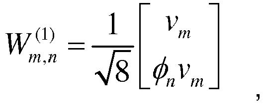


-
Fig. 1 is a structure diagram of a device for generating a precoding matrix according to an embodiment of the disclosure; as shown inFig. 1 , the device includes: aparameter calculator 101, acounter 102, and anelement generator 103. - The
parameter calculator 101 is arranged to calculate, according to the first PMI and the second PMI, the first parameter m and the second parameter n for determining the precoding matrix
element generator 103. - The
counter 102 is arranged to control a row number of an element in the precoding matrix that are to be generated by theelement generator 103. - The
element generator 103 is arranged to generate the element in a (valid_cnt)th row in the precoding matrix according to the received first parameter m, the second parameter n and a row number valid_cnt. - Specifically, the
parameter calculator 101 receives the first PMI and the second PMI configured by the terminal; the value of the first PMI is I1, the value of the second PMI is I2, then m=2×I1+I2[3:2], n=I2[1:0]; the calculated m and n are sent to theelement generator 103. As mentioned above, I1 and I2 can be any integer in [0, 15], and in the practical application, they are 4-bit binary numbers. - Specifically, the
counter 102 generates the row number of the element in the precoding matrix; the row number is marked as valid_cnt in a range is [0, 7], and in the practical application, it is a 3-bit binary number. Thecounter 102 sends the valid-cnt to theelement generator 103, so as to control theelement generator 103 to generate the element of which the row number is valid-cnt in the precoding matrix. The value of valid_cnt gradually increases from 0 to 7, so that theelement generator 103 is controlled to gradually output the element in the zeroth row, the element in the first row ... until the element in the seventh row, thereby generating the whole 8×1 precoding matrix. - In an embodiment, as shown in
Fig .2 , theelement generator 103 includes: a firstlookup table unit 201, a secondlookup table unit 202, a first lookuptable address unit 203, and an elementoutput control unit 204. - The first lookup
table address unit 203 is arranged to generate a base address of the first lookup table unit according to the first parameter m and the row number valid_cnt, and send the base address to the firstlookup table unit 201; here, the first lookuptable address unit 203 may be implemented by a four-to-one multiplexer. - The first
lookup table unit 201 is arranged to store values of elements from the zeroth row to the third row in the precoding matrix calculated in advance, and obtain, according to the base address input by the first lookuptable address unit 203, a value of the corresponding element, and output the value of the corresponding element; here, the firstlookup table unit 201 can be implemented by a Read-Only Memory (ROM) and an auxiliary circuit. - The second
lookup table unit 202 is arranged to store values of an operator influencing elements from the fourth row to the seventh row in the precoding matrix calculated in advance, inquire a value of the operator according to the second parameter n, calculate the product of the value of the element output by the firstlookup table unit 201 and the value of the operator, and send the product to the elementoutput control unit 204 as the value of the corresponding element from the fourth row to the seventh row in the precoding matrix; here, the secondlookup table unit 202 can be implemented by the ROM and the auxiliary circuit. - The element
output control unit 204 is arranged to receive inputs of the firstlookup table unit 201 and the secondlookup table unit 202, and output the (valid_cnt)th element in the precoding matrix according to the row number valid_cnt input by thecounter 102; here, the elementoutput control unit 204 can be implemented by a two-to-one multiplexer. - Specifically, as mentioned above, if the elements from the zeroth row to the third row in the precoding matrix


lookup table unit 201, so that the element Mi of the ith row in the matrix M can be obtained when ixm is taken as the base address to search the firstlookup table unit 201, where 0≤i≤3, and i is an integer. - Correspondingly, if the elements from the fourth row to the seventh row in the 1 precoding matrix


lookup table unit 202, so that the values of the operator φn corresponding to the n can be obtained when the n is taken as the base address to search the secondlookup table unit 202, and then the element Ni of the ith row in the matrix N is calculated; Ni is equal to φn Mi, and corresponds to the element of the (i+4)th row in the precoding matrix
- When the element of the kth row in the precoding matrix

- Therefore, as shown in
Fig. 2 , the first lookuptable address unit 203 receives the 0-4 bits, namely m[4:0], of the first parameter m which is sent by theparameter calculator 101, and receives the 0-1 bits, namely valid_cnt[1:0], of the row number valid_cnt which is sent by thecounter 102; the base address ixm of the first lookup table is obtained by using the characteristic of the four-to-one multiplexer, where i is the value represented by valid_cnt[1:0]; obviously 0≤i≤3, and i is an integer; the base address ixm is sent to the firstlookup table unit 201. - The first
lookup table unit 201 is arranged to obtain the corresponding Mi according to the base address ixm, and send the Mi to the secondlookup table unit 202 and the elementoutput control unit 204. - The second
lookup table unit 202 is arranged to receive the Mi sent by the firstlookup table unit 201, receive the second parameter n sent by theparameter calculator 101, obtain the corresponding operator φn according to the second parameter n and calculate φn Mi, namely Ni, and send the Ni to the elementoutput control unit 204. - When 0≤valid_cnt≤3, the second bit of the valid_cnt, namely valid_cnt[2], is 0; by using the characteristic of the two-to-one multiplexer, the element
output control unit 204 outputs the received Mi, namely the elements from the zeroth row to the third row in the precoding matrix
when 4≤valid_cnt≤7, the second bit of the valid_cnt, namely valid_cnt[2], is 1; by using the characteristic of the two-to-one multiplexer, the elementoutput control unit 204 outputs the Ni sent by the secondlookup table unit 202, namely the elements from the fourth row to the seventh row in the precoding matrix
- After the elements from the zeroth row to the seventh row in the precoding matrix


- All of the parameter calculator, the counter and the element generator in the device for generating a precoding matrix provided by the embodiment of the disclosure, and these units in the element generator can be implemented by a processor in the terminal or a specific logic circuit; in the specific implementation, the processor can be a Central Processing Unit (CPU), a Microprocessor Unit (MPU), a Digital Signal Processor (DSP) or a Field Programmable Gate Array (FPGA).
- The device for generating a precoding matrix provided by the above embodiment can generate a precoding matrix through simple calculation and table lookup, thereby avoiding consuming a large number of storage units.
-
Fig. 3 is a flowchart of a method for generating a precoding matrix provided by the disclosure; as shown in Fig. 7, the method includes the following steps. - In
Step 301, the first parameter and the second parameter for determining the precoding matrix are calculated according to the first PMI and the second PMI. - In
Step 302, a row number of an element in the precoding matrix is controlled by the counter. - In
Step 303, the element corresponding to the row number in the precoding matrix is generated in order according to the first parameter, the second parameter and the row number. - Furthermore, before performing
Step 303, the method further includes the following steps. - The values of the elements from the zeroth row to the third row in the precoding matrix are calculated in advance, and the corresponding relationships between the values of the elements and the first parameter are established, and the corresponding relationships are stored in the first lookup table; and the values of the operator influencing the elements from the fourth row to the seventh row in the precoding matrix are calculated in advance, and corresponding relationships between the values of the operator and the second parameter are established, and the corresponding relationships are stored in the second lookup table.
- Therefore, in the method for generating a precoding matrix,
Step 303 may include the following steps. - The base address of the first lookup table is generated according to the first parameter and the row number; the value of the first element is obtained from the first lookup table according to the base address; a value of the operator is obtained from the second lookup table according to the second parameter; when the row number is from the zeroth row to the third row, the value of the first element is output as the value of the element corresponding to the row number in the precoding matrix; and when the row number is from the fourth row to the seventh row, the product of the value of the first element and the value of the operator is calculated and output as the value corresponding to the row number in the precoding matrix.
- In order to generate the base address of the first lookup table according to the first parameter and the row number, specifically, the base address of the first lookup table is generated according to the zeroth bit to the fourth bit of the first parameter and the zeroth bit to the first bit of the row number.
- It is to be noted that, in the embodiment of the disclosure, if the method for generating a precoding matrix is implemented by software function modules, and the software function modules are sold or used as independent products, they can also be stored in a computer readable storage medium. Based on this understanding, the technical solutions in the embodiments of the disclosure substantially or the part making a contribution to the traditional art can be embodied in the form of software product; the computer software product is stored in a storage medium and includes a number of instructions to make a computer device (which can be a personal computer, a server or a network device, etc.) perform all or part of the method in each embodiment of the disclosure. The above storage medium includes: a USB flash disk, a mobile hard disk, an ROM, a magnetic disk or a compact disc, and other media which can store program codes. In this way, the disclosure is not limited to any particular combination of hardware and software.
- Correspondingly, the embodiment of the disclosure also provides a computer storage medium, which stores computer executable instructions for performing the method for generating a precoding matrix provided in the embodiments of the disclosure.
- Those skilled in the art should understand that the embodiments of the disclosure can provide a method, a system or a computer program product. Thus, forms of hardware embodiments, software embodiments or embodiments integrating software and hardware can be adopted in the disclosure. Moreover, a form of the computer program product implemented on one or more computer available storage media (including, but not limited to, a disk memory, an optical memory and the like) containing computer available program codes can be adopted in the disclosure.
- The disclosure is described with reference to flowcharts and/or block diagrams of the method, the equipment (system) and the computer program product according to the embodiments of the disclosure. It should be understood that each flow and/or block in the flowcharts and/or the block diagrams and a combination of the flows and/or the blocks in the flowcharts and/or the block diagrams can be implemented by computer program instructions. These computer program instructions can be provided for a general computer, a dedicated computer, an embedded processor or processors of other programmable data processing devices to generate a machine, so that an apparatus for realizing functions assigned in one or more flows of the flowcharts and/or one or more blocks of the block diagrams is generated via instructions executed by the computers or the processors of the other programmable data processing devices.
- These computer program instructions can also be stored in a computer readable memory capable of guiding the computers or the other programmable data processing devices to work in a specific mode, so that a manufactured product including an instruction apparatus is generated via the instructions stored in the computer readable memory, and the instruction apparatus realizes the functions assigned in one or more flows of the flowcharts and/or one or more blocks of the block diagrams.
- These computer program instructions can also be loaded to the computers or the other programmable data processing devices, so that processing implemented by the computers is generated by executing a series of operation steps on the computers or the other programmable devices, and therefore the instructions executed on the computers or the other programmable devices provide a step of implementing the functions designated in one or more flows of the flowcharts and/or one or more blocks of the block diagrams.
- The above is only the preferred embodiments of the disclosure and not intended to limit the scope of protection of the disclosure.
- In the disclosure, the first parameter and the second parameter for determining the precoding matrix are calculated according to the first PMI and the second PMI; the row number of the element in the precoding matrix is controlled by the counter; the element corresponding to the row number in the precoding matrix is generated in order according to the first parameter, the second parameter and the row number; and the element in the precoding matrix are output in an ascending order of row numbers; in such a manner, a precoding matrix can be generated through simple calculation and table lookup, thereby avoiding consuming a large number of storage units.
Claims (11)
- A device for generating a precoding matrix, comprising: a parameter calculator, a counter and an element generator; wherein,
the parameter calculator is arranged to calculate, according to a first Precoding Matrix Identifier (PMI) and a second PMI, a first parameter and a second parameter for determining the precoding matrix, and send the first parameter and the second parameter to the element generator;
the counter is arranged to control a row number of an element in the precoding matrix that is to be generated by the element generator; and
the element generator is arranged to generate the element corresponding to the row number in the precoding matrix according to the received first parameter and second parameter and the row number. - The device for generating a precoding matrix according to claim 1, wherein the element generator comprises: a first lookup table unit, a second lookup table unit, a first lookup table address unit, and an element output control unit; wherein,
the first lookup table unit is arranged to store values of elements from a zeroth row to a third row in the precoding matrix calculated in advance, obtain, according to a base address input by the first lookup table address unit, a value of the corresponding element and output the value of the corresponding element;
the second lookup table unit is arranged to store values of an operator influencing elements from a fourth row to a seventh row in the precoding matrix calculated in advance, inquire a value of the operator according to the second parameter, calculate product of the value of the element output by the first lookup table unit and the value of the operator, and send the product to the element output control unit as the value of the corresponding element from the fourth row to the seventh row in the precoding matrix;
the first lookup table address unit is arranged to generate the base address of the first lookup table unit according to the first parameter and the row number, and send the base address to the first lookup table unit; and
the element output control unit is arranged to receive inputs of the first lookup table unit and the second lookup table unit, and output, according to the row number input by the counter, the element of the precoding matrix corresponding to the row number. - The device for generating a precoding matrix according to claim 2, wherein the first lookup table address unit is implemented by a four-to-one multiplexer.
- The device for generating a precoding matrix according to claim 2, wherein the element output control unit is implemented by a two-to-one multiplexer.
- The device for generating a precoding matrix according to any one of claims 1 to 4, wherein the precoding matrix is:

- A method for generating a precoding matrix, comprising:calculating a first parameter and a second parameter for determining the precoding matrix according to a first Precoding Matrix Identifier (PMI) and a second PMI;controlling a row number of an element in the precoding matrix by a counter;generating in order the element corresponding to the row number in the precoding matrix according to the first parameter, the second parameter and the row number; andoutputting elements in the precoding matrix in an ascending order of row numbers.
- The method for generating a precoding matrix according to claim 6, wherein before generating in order the element corresponding to the row number in the precoding matrix according to the first parameter, the second parameter and the row number, the method further comprises:calculating in advance values of elements from a zeroth row to a third row in the precoding matrix, and establishing corresponding relationships between the values of the elements and the first parameter, and storing the corresponding relationships in a first lookup table; andcalculating in advance values of an operator influencing elements from a fourth row to a seventh row in the precoding matrix, and establishing corresponding relationships between the values of the operator and the second parameter, and storing the corresponding relationships in a second lookup table.
- The method for generating a precoding matrix according to claim 7, wherein generating in order the element corresponding to the row number in the precoding matrix according to the first parameter, the second parameter and the row number comprises:generating a base address of the first lookup table according to the first parameter and the row number;obtaining a value of a first element from the first lookup table according to the base address;obtaining the value of the operator from the second lookup table according to the second parameter;when the row number is from the zeroth row to the third row, outputting the value of the first element as the value of the element corresponding to the row number in the precoding matrix; andwhen the row number is from a fourth row to a seventh row, calculating and outputting the product of the value of the first element and the value of the operator as the value corresponding to the row number in the precoding matrix.
- The method for generating a precoding matrix according to claim 8, wherein generating the base address of the first lookup table according to the first parameter and the row number comprises:generating the base address of the first lookup table according to a zeroth bit to a fourth bit of the first parameter and a zeroth bit to a first bit of the row number.
- The method for generating a precoding matrix according to any one of claims 6 to 9, wherein the precoding matrix is:

- A computer storage medium storing computer executable instructions for performing the method for generating a precoding matrix according to any one of claims 6 to 10.
Applications Claiming Priority (2)
| Application Number | Priority Date | Filing Date | Title |
|---|---|---|---|
| CN201410493837.4A CN105515630A (en) | 2014-09-24 | 2014-09-24 | Pre-encoding matrix generation apparatus and method |
| PCT/CN2015/072146 WO2016045292A1 (en) | 2014-09-24 | 2015-02-03 | Device and method for generating precoding matrix, and storage medium |
Publications (3)
| Publication Number | Publication Date |
|---|---|
| EP3188395A1 true EP3188395A1 (en) | 2017-07-05 |
| EP3188395A4 EP3188395A4 (en) | 2017-08-30 |
| EP3188395B1 EP3188395B1 (en) | 2019-07-24 |
Family
ID=55580206
Family Applications (1)
| Application Number | Title | Priority Date | Filing Date |
|---|---|---|---|
| EP15844462.0A Active EP3188395B1 (en) | 2014-09-24 | 2015-02-03 | Device and method for generating precoding matrix, and storage medium |
Country Status (4)
| Country | Link |
|---|---|
| US (1) | US10038482B2 (en) |
| EP (1) | EP3188395B1 (en) |
| CN (1) | CN105515630A (en) |
| WO (1) | WO2016045292A1 (en) |
Families Citing this family (1)
| Publication number | Priority date | Publication date | Assignee | Title |
|---|---|---|---|---|
| CN108988988B (en) * | 2018-06-29 | 2020-05-19 | 华中科技大学 | RCM (Radar Cross-correlation) encoder and encoding method based on two-stage lookup table of quasi-cyclic matrix |
Family Cites Families (16)
| Publication number | Priority date | Publication date | Assignee | Title |
|---|---|---|---|---|
| US8982969B2 (en) * | 2007-05-03 | 2015-03-17 | Broadcom Corporation | Method and system for CQI/PMI feedback for precoded MIMO systems utilizing differential codebooks |
| US8311144B1 (en) * | 2008-04-01 | 2012-11-13 | Marvell International Ltd. | Systems and methods for efficient codebook searches |
| KR101749845B1 (en) * | 2008-04-29 | 2017-06-21 | 애플 인크. | Improved performance for a multiple antenna beamforming cellular network |
| CN101877684B (en) | 2009-04-28 | 2012-11-14 | 电信科学技术研究院 | Method and device for determining precoding matrix |
| CN102082635B (en) | 2010-03-30 | 2013-04-10 | 电信科学技术研究院 | Codebook storage and information transceiving method and device using codebook |
| CN102244565B (en) | 2010-05-11 | 2014-02-12 | 电信科学技术研究院 | Method and device for generating channel information feedback and precoding matrix |
| KR101231487B1 (en) | 2010-06-03 | 2013-02-07 | (주)휴맥스 | Method for Differential Precoding and Base Station for Supporting That Method |
| US8711907B2 (en) * | 2010-10-01 | 2014-04-29 | Intel Corporation | PMI feedback with codebook interpolation |
| CN102651676B (en) | 2011-02-24 | 2015-01-21 | 华为技术有限公司 | Method and device for determining pre-coding matrix |
| US9019850B2 (en) * | 2011-04-11 | 2015-04-28 | Qualcomm Incorporated | CSI reporting for multiple carriers with different system configurations |
| US20120314590A1 (en) * | 2011-06-10 | 2012-12-13 | Sharp Laboratories Of America, Inc. | Enhanced precoding feedback for multiple-user multiple-input and multiple-output (mimo) |
| CN102368698B (en) * | 2011-11-10 | 2014-04-16 | 电信科学技术研究院 | Method and device for transmitting Precoding Matrix Indicator (PMI) information |
| CN103188032B (en) | 2011-12-29 | 2015-11-25 | 航通互联网信息服务有限责任公司 | A kind of multi-user downlink precode generation method, Apparatus and system |
| JP6407144B2 (en) * | 2012-06-04 | 2018-10-17 | インターデイジタル パテント ホールディングス インコーポレイテッド | Communication of channel state information (CSI) of multiple transmission points |
| CN103051420B (en) | 2012-12-14 | 2015-04-08 | 无锡北邮感知技术产业研究院有限公司 | Codebook generation method of MIMO (Multiple-Input Multiple-output) system |
| CN104009785B (en) * | 2013-02-25 | 2017-11-28 | 华为技术有限公司 | Code book feedback method, user equipment and base station |
-
2014
- 2014-09-24 CN CN201410493837.4A patent/CN105515630A/en not_active Withdrawn
-
2015
- 2015-02-03 WO PCT/CN2015/072146 patent/WO2016045292A1/en not_active Ceased
- 2015-02-03 US US15/513,742 patent/US10038482B2/en active Active
- 2015-02-03 EP EP15844462.0A patent/EP3188395B1/en active Active
Also Published As
| Publication number | Publication date |
|---|---|
| WO2016045292A1 (en) | 2016-03-31 |
| EP3188395B1 (en) | 2019-07-24 |
| US10038482B2 (en) | 2018-07-31 |
| EP3188395A4 (en) | 2017-08-30 |
| US20170288749A1 (en) | 2017-10-05 |
| CN105515630A (en) | 2016-04-20 |
Similar Documents
| Publication | Publication Date | Title |
|---|---|---|
| EP3944511A1 (en) | Channel state information reporting method and device | |
| EP3343777A1 (en) | Methods and apparatuses for transmitting coding indication information and determining precoding matrix | |
| EP3432482B1 (en) | Csi feedback method, precoding method, terminal and base station | |
| US12574079B2 (en) | Precoding matrix indication method, precoding matrix determination method, apparatuses and medium | |
| US10574409B2 (en) | Information notification method and channel state information process execution method | |
| EP3358752A1 (en) | Method and apparatus for selecting a resource, and electronic device | |
| JP7153078B2 (en) | SRS power headroom reporting method, terminal equipment and computer storage medium | |
| EP2963964B1 (en) | Method for ensuring channel phase continuity between rb groups after precoding, base station, and computer readable storage medium | |
| KR102151334B1 (en) | Data transmission method and device | |
| EP4184841A1 (en) | Csi measurement reporting method, terminal, and network-side device | |
| US10855343B2 (en) | Method, apparatus and system for acquiring codebook by channel state information report type | |
| EP4044443B1 (en) | Method and device for transmitting feedback information | |
| US11424806B2 (en) | Method and device for determining precoding, method and device for detecting data, storage medium and electronic device | |
| EP3367583A1 (en) | Method and apparatus for transmitting channel state information | |
| EP4195523A1 (en) | Method and apparatus for determining sending power of uplink element, and device and storage medium | |
| US10038482B2 (en) | Device and method for generating precoding matrix, and storage medium | |
| CN103795450A (en) | Methods for transmitting coding indication information and determining pre-coding matrix, system and equipment | |
| EP4369621A1 (en) | Channel state information reporting method, channel state information receiving method, communication node, and storage medium | |
| WO2017133549A1 (en) | Method and device for reducing complexity of channel quantization | |
| CN105337692B (en) | Down channel method for precoding and device | |
| WO2019232682A1 (en) | Codebook processing method and system, network device, user equipment, and storage medium | |
| US9780849B2 (en) | Method and system for performance testing | |
| CN106034008A (en) | Value determination method and value determination device for precoding type indicator | |
| WO2020006689A1 (en) | Method for determining channel state information, terminal device, and storage medium | |
| CN104660364B (en) | Channel status measuring method, device and user terminal |
Legal Events
| Date | Code | Title | Description |
|---|---|---|---|
| STAA | Information on the status of an ep patent application or granted ep patent |
Free format text: STATUS: THE INTERNATIONAL PUBLICATION HAS BEEN MADE |
|
| PUAI | Public reference made under article 153(3) epc to a published international application that has entered the european phase |
Free format text: ORIGINAL CODE: 0009012 |
|
| STAA | Information on the status of an ep patent application or granted ep patent |
Free format text: STATUS: REQUEST FOR EXAMINATION WAS MADE |
|
| 17P | Request for examination filed |
Effective date: 20170330 |
|
| AK | Designated contracting states |
Kind code of ref document: A1 Designated state(s): AL AT BE BG CH CY CZ DE DK EE ES FI FR GB GR HR HU IE IS IT LI LT LU LV MC MK MT NL NO PL PT RO RS SE SI SK SM TR |
|
| AX | Request for extension of the european patent |
Extension state: BA ME |
|
| REG | Reference to a national code |
Ref country code: DE Ref legal event code: R079 Ref document number: 602015034530 Country of ref document: DE Free format text: PREVIOUS MAIN CLASS: H04L0001060000 Ipc: H04L0025030000 |
|
| A4 | Supplementary search report drawn up and despatched |
Effective date: 20170801 |
|
| RIC1 | Information provided on ipc code assigned before grant |
Ipc: H04L 25/03 20060101AFI20170726BHEP Ipc: H04B 7/0456 20170101ALI20170726BHEP |
|
| DAX | Request for extension of the european patent (deleted) | ||
| GRAP | Despatch of communication of intention to grant a patent |
Free format text: ORIGINAL CODE: EPIDOSNIGR1 |
|
| STAA | Information on the status of an ep patent application or granted ep patent |
Free format text: STATUS: GRANT OF PATENT IS INTENDED |
|
| INTG | Intention to grant announced |
Effective date: 20190212 |
|
| GRAS | Grant fee paid |
Free format text: ORIGINAL CODE: EPIDOSNIGR3 |
|
| GRAA | (expected) grant |
Free format text: ORIGINAL CODE: 0009210 |
|
| STAA | Information on the status of an ep patent application or granted ep patent |
Free format text: STATUS: THE PATENT HAS BEEN GRANTED |
|
| AK | Designated contracting states |
Kind code of ref document: B1 Designated state(s): AL AT BE BG CH CY CZ DE DK EE ES FI FR GB GR HR HU IE IS IT LI LT LU LV MC MK MT NL NO PL PT RO RS SE SI SK SM TR |
|
| REG | Reference to a national code |
Ref country code: GB Ref legal event code: FG4D |
|
| REG | Reference to a national code |
Ref country code: CH Ref legal event code: EP |
|
| REG | Reference to a national code |
Ref country code: DE Ref legal event code: R096 Ref document number: 602015034530 Country of ref document: DE |
|
| REG | Reference to a national code |
Ref country code: AT Ref legal event code: REF Ref document number: 1159585 Country of ref document: AT Kind code of ref document: T Effective date: 20190815 |
|
| REG | Reference to a national code |
Ref country code: IE Ref legal event code: FG4D |
|
| REG | Reference to a national code |
Ref country code: NL Ref legal event code: MP Effective date: 20190724 |
|
| REG | Reference to a national code |
Ref country code: LT Ref legal event code: MG4D |
|
| REG | Reference to a national code |
Ref country code: AT Ref legal event code: MK05 Ref document number: 1159585 Country of ref document: AT Kind code of ref document: T Effective date: 20190724 |
|
| PG25 | Lapsed in a contracting state [announced via postgrant information from national office to epo] |
Ref country code: FI Free format text: LAPSE BECAUSE OF FAILURE TO SUBMIT A TRANSLATION OF THE DESCRIPTION OR TO PAY THE FEE WITHIN THE PRESCRIBED TIME-LIMIT Effective date: 20190724 Ref country code: HR Free format text: LAPSE BECAUSE OF FAILURE TO SUBMIT A TRANSLATION OF THE DESCRIPTION OR TO PAY THE FEE WITHIN THE PRESCRIBED TIME-LIMIT Effective date: 20190724 Ref country code: SE Free format text: LAPSE BECAUSE OF FAILURE TO SUBMIT A TRANSLATION OF THE DESCRIPTION OR TO PAY THE FEE WITHIN THE PRESCRIBED TIME-LIMIT Effective date: 20190724 Ref country code: NO Free format text: LAPSE BECAUSE OF FAILURE TO SUBMIT A TRANSLATION OF THE DESCRIPTION OR TO PAY THE FEE WITHIN THE PRESCRIBED TIME-LIMIT Effective date: 20191024 Ref country code: AT Free format text: LAPSE BECAUSE OF FAILURE TO SUBMIT A TRANSLATION OF THE DESCRIPTION OR TO PAY THE FEE WITHIN THE PRESCRIBED TIME-LIMIT Effective date: 20190724 Ref country code: LT Free format text: LAPSE BECAUSE OF FAILURE TO SUBMIT A TRANSLATION OF THE DESCRIPTION OR TO PAY THE FEE WITHIN THE PRESCRIBED TIME-LIMIT Effective date: 20190724 Ref country code: NL Free format text: LAPSE BECAUSE OF FAILURE TO SUBMIT A TRANSLATION OF THE DESCRIPTION OR TO PAY THE FEE WITHIN THE PRESCRIBED TIME-LIMIT Effective date: 20190724 Ref country code: BG Free format text: LAPSE BECAUSE OF FAILURE TO SUBMIT A TRANSLATION OF THE DESCRIPTION OR TO PAY THE FEE WITHIN THE PRESCRIBED TIME-LIMIT Effective date: 20191024 Ref country code: PT Free format text: LAPSE BECAUSE OF FAILURE TO SUBMIT A TRANSLATION OF THE DESCRIPTION OR TO PAY THE FEE WITHIN THE PRESCRIBED TIME-LIMIT Effective date: 20191125 |
|
| PG25 | Lapsed in a contracting state [announced via postgrant information from national office to epo] |
Ref country code: ES Free format text: LAPSE BECAUSE OF FAILURE TO SUBMIT A TRANSLATION OF THE DESCRIPTION OR TO PAY THE FEE WITHIN THE PRESCRIBED TIME-LIMIT Effective date: 20190724 Ref country code: GR Free format text: LAPSE BECAUSE OF FAILURE TO SUBMIT A TRANSLATION OF THE DESCRIPTION OR TO PAY THE FEE WITHIN THE PRESCRIBED TIME-LIMIT Effective date: 20191025 Ref country code: LV Free format text: LAPSE BECAUSE OF FAILURE TO SUBMIT A TRANSLATION OF THE DESCRIPTION OR TO PAY THE FEE WITHIN THE PRESCRIBED TIME-LIMIT Effective date: 20190724 Ref country code: AL Free format text: LAPSE BECAUSE OF FAILURE TO SUBMIT A TRANSLATION OF THE DESCRIPTION OR TO PAY THE FEE WITHIN THE PRESCRIBED TIME-LIMIT Effective date: 20190724 Ref country code: IS Free format text: LAPSE BECAUSE OF FAILURE TO SUBMIT A TRANSLATION OF THE DESCRIPTION OR TO PAY THE FEE WITHIN THE PRESCRIBED TIME-LIMIT Effective date: 20191124 Ref country code: RS Free format text: LAPSE BECAUSE OF FAILURE TO SUBMIT A TRANSLATION OF THE DESCRIPTION OR TO PAY THE FEE WITHIN THE PRESCRIBED TIME-LIMIT Effective date: 20190724 |
|
| PG25 | Lapsed in a contracting state [announced via postgrant information from national office to epo] |
Ref country code: TR Free format text: LAPSE BECAUSE OF FAILURE TO SUBMIT A TRANSLATION OF THE DESCRIPTION OR TO PAY THE FEE WITHIN THE PRESCRIBED TIME-LIMIT Effective date: 20190724 |
|
| PG25 | Lapsed in a contracting state [announced via postgrant information from national office to epo] |
Ref country code: EE Free format text: LAPSE BECAUSE OF FAILURE TO SUBMIT A TRANSLATION OF THE DESCRIPTION OR TO PAY THE FEE WITHIN THE PRESCRIBED TIME-LIMIT Effective date: 20190724 Ref country code: RO Free format text: LAPSE BECAUSE OF FAILURE TO SUBMIT A TRANSLATION OF THE DESCRIPTION OR TO PAY THE FEE WITHIN THE PRESCRIBED TIME-LIMIT Effective date: 20190724 Ref country code: PL Free format text: LAPSE BECAUSE OF FAILURE TO SUBMIT A TRANSLATION OF THE DESCRIPTION OR TO PAY THE FEE WITHIN THE PRESCRIBED TIME-LIMIT Effective date: 20190724 Ref country code: IT Free format text: LAPSE BECAUSE OF FAILURE TO SUBMIT A TRANSLATION OF THE DESCRIPTION OR TO PAY THE FEE WITHIN THE PRESCRIBED TIME-LIMIT Effective date: 20190724 Ref country code: DK Free format text: LAPSE BECAUSE OF FAILURE TO SUBMIT A TRANSLATION OF THE DESCRIPTION OR TO PAY THE FEE WITHIN THE PRESCRIBED TIME-LIMIT Effective date: 20190724 |
|
| PG25 | Lapsed in a contracting state [announced via postgrant information from national office to epo] |
Ref country code: SK Free format text: LAPSE BECAUSE OF FAILURE TO SUBMIT A TRANSLATION OF THE DESCRIPTION OR TO PAY THE FEE WITHIN THE PRESCRIBED TIME-LIMIT Effective date: 20190724 Ref country code: CZ Free format text: LAPSE BECAUSE OF FAILURE TO SUBMIT A TRANSLATION OF THE DESCRIPTION OR TO PAY THE FEE WITHIN THE PRESCRIBED TIME-LIMIT Effective date: 20190724 Ref country code: SM Free format text: LAPSE BECAUSE OF FAILURE TO SUBMIT A TRANSLATION OF THE DESCRIPTION OR TO PAY THE FEE WITHIN THE PRESCRIBED TIME-LIMIT Effective date: 20190724 Ref country code: IS Free format text: LAPSE BECAUSE OF FAILURE TO SUBMIT A TRANSLATION OF THE DESCRIPTION OR TO PAY THE FEE WITHIN THE PRESCRIBED TIME-LIMIT Effective date: 20200224 |
|
| REG | Reference to a national code |
Ref country code: DE Ref legal event code: R097 Ref document number: 602015034530 Country of ref document: DE |
|
| PLBE | No opposition filed within time limit |
Free format text: ORIGINAL CODE: 0009261 |
|
| STAA | Information on the status of an ep patent application or granted ep patent |
Free format text: STATUS: NO OPPOSITION FILED WITHIN TIME LIMIT |
|
| PG2D | Information on lapse in contracting state deleted |
Ref country code: IS |
|
| 26N | No opposition filed |
Effective date: 20200603 |
|
| PG25 | Lapsed in a contracting state [announced via postgrant information from national office to epo] |
Ref country code: SI Free format text: LAPSE BECAUSE OF FAILURE TO SUBMIT A TRANSLATION OF THE DESCRIPTION OR TO PAY THE FEE WITHIN THE PRESCRIBED TIME-LIMIT Effective date: 20190724 |
|
| REG | Reference to a national code |
Ref country code: CH Ref legal event code: PL |
|
| GBPC | Gb: european patent ceased through non-payment of renewal fee |
Effective date: 20200203 |
|
| REG | Reference to a national code |
Ref country code: BE Ref legal event code: MM Effective date: 20200229 |
|
| PG25 | Lapsed in a contracting state [announced via postgrant information from national office to epo] |
Ref country code: MC Free format text: LAPSE BECAUSE OF FAILURE TO SUBMIT A TRANSLATION OF THE DESCRIPTION OR TO PAY THE FEE WITHIN THE PRESCRIBED TIME-LIMIT Effective date: 20190724 Ref country code: LU Free format text: LAPSE BECAUSE OF NON-PAYMENT OF DUE FEES Effective date: 20200203 |
|
| PG25 | Lapsed in a contracting state [announced via postgrant information from national office to epo] |
Ref country code: CH Free format text: LAPSE BECAUSE OF NON-PAYMENT OF DUE FEES Effective date: 20200229 Ref country code: LI Free format text: LAPSE BECAUSE OF NON-PAYMENT OF DUE FEES Effective date: 20200229 |
|
| PG25 | Lapsed in a contracting state [announced via postgrant information from national office to epo] |
Ref country code: GB Free format text: LAPSE BECAUSE OF NON-PAYMENT OF DUE FEES Effective date: 20200203 Ref country code: FR Free format text: LAPSE BECAUSE OF NON-PAYMENT OF DUE FEES Effective date: 20200229 Ref country code: IE Free format text: LAPSE BECAUSE OF NON-PAYMENT OF DUE FEES Effective date: 20200203 |
|
| PG25 | Lapsed in a contracting state [announced via postgrant information from national office to epo] |
Ref country code: BE Free format text: LAPSE BECAUSE OF NON-PAYMENT OF DUE FEES Effective date: 20200229 |
|
| PG25 | Lapsed in a contracting state [announced via postgrant information from national office to epo] |
Ref country code: MT Free format text: LAPSE BECAUSE OF FAILURE TO SUBMIT A TRANSLATION OF THE DESCRIPTION OR TO PAY THE FEE WITHIN THE PRESCRIBED TIME-LIMIT Effective date: 20190724 Ref country code: CY Free format text: LAPSE BECAUSE OF FAILURE TO SUBMIT A TRANSLATION OF THE DESCRIPTION OR TO PAY THE FEE WITHIN THE PRESCRIBED TIME-LIMIT Effective date: 20190724 |
|
| PG25 | Lapsed in a contracting state [announced via postgrant information from national office to epo] |
Ref country code: MK Free format text: LAPSE BECAUSE OF FAILURE TO SUBMIT A TRANSLATION OF THE DESCRIPTION OR TO PAY THE FEE WITHIN THE PRESCRIBED TIME-LIMIT Effective date: 20190724 |
|
| PGFP | Annual fee paid to national office [announced via postgrant information from national office to epo] |
Ref country code: DE Payment date: 20251210 Year of fee payment: 12 |