EP3188353A1 - Current estimation circuit for rectification circuit, ac-dc converter, electric power control device, current estimation circuit, and method and program for current estimation - Google Patents
Current estimation circuit for rectification circuit, ac-dc converter, electric power control device, current estimation circuit, and method and program for current estimation Download PDFInfo
- Publication number
- EP3188353A1 EP3188353A1 EP15851081.8A EP15851081A EP3188353A1 EP 3188353 A1 EP3188353 A1 EP 3188353A1 EP 15851081 A EP15851081 A EP 15851081A EP 3188353 A1 EP3188353 A1 EP 3188353A1
- Authority
- EP
- European Patent Office
- Prior art keywords
- current
- phase
- rectification
- voltages
- voltage
- Prior art date
- Legal status (The legal status is an assumption and is not a legal conclusion. Google has not performed a legal analysis and makes no representation as to the accuracy of the status listed.)
- Ceased
Links
Images


Classifications
-
- H—ELECTRICITY
- H02—GENERATION; CONVERSION OR DISTRIBUTION OF ELECTRIC POWER
- H02M—APPARATUS FOR CONVERSION BETWEEN AC AND AC, BETWEEN AC AND DC, OR BETWEEN DC AND DC, AND FOR USE WITH MAINS OR SIMILAR POWER SUPPLY SYSTEMS; CONVERSION OF DC OR AC INPUT POWER INTO SURGE OUTPUT POWER; CONTROL OR REGULATION THEREOF
- H02M7/00—Conversion of AC power input into DC power output; Conversion of DC power input into AC power output
- H02M7/02—Conversion of AC power input into DC power output without possibility of reversal
- H02M7/04—Conversion of AC power input into DC power output without possibility of reversal by static converters
- H02M7/06—Conversion of AC power input into DC power output without possibility of reversal by static converters using discharge tubes without control electrode or semiconductor devices without control electrode
-
- H—ELECTRICITY
- H02—GENERATION; CONVERSION OR DISTRIBUTION OF ELECTRIC POWER
- H02M—APPARATUS FOR CONVERSION BETWEEN AC AND AC, BETWEEN AC AND DC, OR BETWEEN DC AND DC, AND FOR USE WITH MAINS OR SIMILAR POWER SUPPLY SYSTEMS; CONVERSION OF DC OR AC INPUT POWER INTO SURGE OUTPUT POWER; CONTROL OR REGULATION THEREOF
- H02M1/00—Details of apparatus for conversion
- H02M1/32—Means for protecting converters other than automatic disconnection
-
- H—ELECTRICITY
- H02—GENERATION; CONVERSION OR DISTRIBUTION OF ELECTRIC POWER
- H02M—APPARATUS FOR CONVERSION BETWEEN AC AND AC, BETWEEN AC AND DC, OR BETWEEN DC AND DC, AND FOR USE WITH MAINS OR SIMILAR POWER SUPPLY SYSTEMS; CONVERSION OF DC OR AC INPUT POWER INTO SURGE OUTPUT POWER; CONTROL OR REGULATION THEREOF
- H02M7/00—Conversion of AC power input into DC power output; Conversion of DC power input into AC power output
- H02M7/02—Conversion of AC power input into DC power output without possibility of reversal
- H02M7/04—Conversion of AC power input into DC power output without possibility of reversal by static converters
- H02M7/12—Conversion of AC power input into DC power output without possibility of reversal by static converters using discharge tubes with control electrode or semiconductor devices with control electrode
- H02M7/21—Conversion of AC power input into DC power output without possibility of reversal by static converters using discharge tubes with control electrode or semiconductor devices with control electrode using devices of a triode or transistor type requiring continuous application of a control signal
- H02M7/217—Conversion of AC power input into DC power output without possibility of reversal by static converters using discharge tubes with control electrode or semiconductor devices with control electrode using devices of a triode or transistor type requiring continuous application of a control signal using semiconductor devices only
-
- H—ELECTRICITY
- H02—GENERATION; CONVERSION OR DISTRIBUTION OF ELECTRIC POWER
- H02M—APPARATUS FOR CONVERSION BETWEEN AC AND AC, BETWEEN AC AND DC, OR BETWEEN DC AND DC, AND FOR USE WITH MAINS OR SIMILAR POWER SUPPLY SYSTEMS; CONVERSION OF DC OR AC INPUT POWER INTO SURGE OUTPUT POWER; CONTROL OR REGULATION THEREOF
- H02M7/00—Conversion of AC power input into DC power output; Conversion of DC power input into AC power output
- H02M7/42—Conversion of DC power input into AC power output without possibility of reversal
- H02M7/44—Conversion of DC power input into AC power output without possibility of reversal by static converters
- H02M7/48—Conversion of DC power input into AC power output without possibility of reversal by static converters using discharge tubes with control electrode or semiconductor devices with control electrode
-
- H—ELECTRICITY
- H02—GENERATION; CONVERSION OR DISTRIBUTION OF ELECTRIC POWER
- H02M—APPARATUS FOR CONVERSION BETWEEN AC AND AC, BETWEEN AC AND DC, OR BETWEEN DC AND DC, AND FOR USE WITH MAINS OR SIMILAR POWER SUPPLY SYSTEMS; CONVERSION OF DC OR AC INPUT POWER INTO SURGE OUTPUT POWER; CONTROL OR REGULATION THEREOF
- H02M1/00—Details of apparatus for conversion
- H02M1/0003—Details of control, feedback or regulation circuits
- H02M1/0009—Devices or circuits for detecting current in a converter
Definitions
- the present invention relates to a current estimation circuit for a rectification circuit, an AC-DC converter, an electric power control device, a current estimation circuit, and a method and program for current estimation.
- the system that generates a voltage to drive a motor includes an AC-DC converter and an inverter.
- the AC-DC converter converts the alternating voltage supplied from the three-phase alternating power supply from the alternating voltage into a DC voltage
- the inverter converts the DC voltage converted by the AC-DC converter into an alternating voltage.
- a device disclosed in PTL 1 includes a pulse width modulation (PWM) rectification circuit and a PWM inverter. This device determines whether or not there is an abnormality in a supply voltage for the PWM rectification circuit on the basis of a current. This device decreases an output frequency or a duty of the PWM inverter in a case where it is determined that there is an abnormality, to thereby protect the circuit.
- PWM pulse width modulation
- an excessive current may flow into a device to which an electric power is supplied from the three-phase alternating power supply or a device connected to a stage subsequent to such a device. In this case, a malfunction is likely to occur in the system.
- An object of the present invention is to provide a current estimation circuit for a rectification circuit, an AC-DC converter, an electric power control device, a current estimation circuit, and a method and program for current estimation capable of solving the above problem.
- a current estimation circuit for a rectification circuit includes a phase identification part that identifies respective phases of a plurality of alternating voltages that are output from a power supply; and a current identification part that identifies currents corresponding to voltages after rectification of the plurality of alternating voltages at time intervals determined on the basis of the respective phases identified by the phase identification part.
- the current identification part may identify the currents corresponding to the voltages after rectification on the basis of a current flowing through a resistor after the rectification.
- the current identification part may identify the currents corresponding to the voltages after rectification on the basis of a current detected by a current transformer after the rectification.
- the current estimation circuit for a rectification circuit in any one of the first to third aspects may further include a current estimation part that estimates respective currents corresponding to the plurality of alternating voltages on the basis of the currents corresponding to the voltages after rectification identified by the current identification part.
- the current estimation circuit for a rectification circuit in the fourth aspect may further include a current determination part that determines whether or not each of the currents estimated by the current estimation part exceeds a current abnormality detection threshold value; and a current limiting part that limits an upper limit of the respective estimated currents corresponding to the determination in a case where the current determination part determines that the respective estimated currents exceed the current abnormality detection threshold value.
- an AC-DC converter includes the current estimation circuit for a rectification circuit in any one of the first to fifth aspects; and a smoothing circuit that smoothes a voltage output by the rectification circuit.
- an electric power control device includes the AC-DC converter in the sixth aspect; and an inverter that converts a DC voltage output by the AC-DC converter into an alternating voltage.
- a current estimation circuit includes a current estimation part that estimates respective currents corresponding to a plurality of alternating voltages output from a power supply on the basis of currents corresponding to voltages after rectification of the plurality of alternating voltages at time intervals determined on the basis of respective phases of the plurality of alternating voltages.
- the current estimation circuit in the eighth aspect may further include a current determination part that determines whether or not each of the currents estimated by the current estimation part exceeds a current abnormality detection threshold value; and a current limiting part that limits an upper limit of the respective estimated currents corresponding to the determination in a case where the current determination part determines that the respective estimated currents exceed the current abnormality detection threshold value.
- a current estimation method includes identifying respective phases of a plurality of alternating voltages that are output from a power supply; and identifying currents corresponding to voltages after rectification of the plurality of alternating voltages at time intervals determined on the basis of the respective identified phases.
- a current estimation method includes estimating respective currents corresponding to a plurality of alternating voltages output from a power supply on the basis of currents corresponding to voltages after rectification of the plurality of alternating voltages at time intervals determined on the basis of respective phases of the plurality of alternating voltages.
- a program causes a computer to execute estimating respective currents corresponding to a plurality of alternating voltages output from a power supply on the basis of currents corresponding to voltages after rectification of the plurality of alternating voltages at time intervals determined on the basis of respective phases of the plurality of alternating voltages.
- the current estimation circuit for a rectification circuit the AC-DC converter, the electric power control device, the current estimation circuit, and the method and the program for current estimation, it is possible to easily detect an abnormal state in a system and protect the system in a case where respective voltages of the R phase, the S phase, and the T phase of the three-phase alternating power supply enter an unbalanced state.
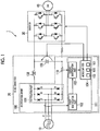
- Fig. 1 is a diagram illustrating an example of a configuration of the electric power control device 1 including a rectification circuit 100 according to an embodiment of the present invention.
- the electric power control device 1 includes an alternating power supply 10, an AC (Alternative Current)-DC (Direct Current) converter 20, an inverter 30, and a motor 40.
- the alternating power supply 10 outputs a plurality of alternating voltages.
- the alternating power supply 10 outputs three sinusoidal alternating voltages (R phase, S phase, and T phase) of which phases are mutually shifted by 120° to a rectification part 101.
- the AC-DC converter 20 includes a rectification circuit 100, a reactor 108, and a capacitor 109.
- the rectification circuit 100 includes the rectification part 101, a current detection resistor 110, and a current estimation circuit 111.
- the rectification part 101 rectifies the alternating voltage output from the alternating power supply 10.
- the rectification part 101 includes six diodes D1 to D6.
- An anode of the diode D1 is connected to a cathode of the diode D2.
- An anode of the diode D3 is connected to a cathode of the diode D4.
- An anode of the diode D5 is connected to a cathode of the diode D6.
- the alternating power supply 10 outputs an R-phase alternating voltage to the anode of the diode D1.
- the alternating power supply 10 outputs an S-phase alternating voltage to the anode of the diode D3.
- the alternating power supply 10 outputs a T-phase alternating voltage to the anode of the diode D5.
- the rectification part 101 performs full-wave rectification on the alternating voltage that the alternating power supply 10 outputs to the rectification part 101.
- the current detection resistor 110 is a resistor that detects a converter current flowing through the AC-DC converter 20.
- the current estimation circuit 111 includes a phase identification part 102, a current identification part 103, and a microcomputer 104.
- the phase identification part 102 identifies each phase of the plurality of alternating voltages output from the alternating power supply 10.
- the phase identification part 102 includes a zero cross detection circuit.
- the zero cross detection circuit included in the phase identification part 102 detects a zero cross point using an inter-line voltage or a phase voltage.
- the zero cross point is a point at which a bias voltage indicating a zero amplitude of the alternating voltage crosses the alternating voltage.
- the zero cross detection circuit included in the phase identification part 102 detects a zero cross point of the R-phase alternating voltage.
- the phase identification part 102 identifies a zero cross timing of the R-phase alternating voltage on the basis of the zero cross point of the R-phase alternating voltage detected by the zero cross detection circuit.
- the phase identification part 102 identifies a timing obtained by shifting the identified zero cross timing of the R-phase alternating voltage by a timing (+1/3 period) corresponding to the phase of +120° as a zero cross timing of the S-phase alternating voltage.
- the phase identification part 102 identifies a timing obtained by shifting the identified zero cross timing of the S-phase alternating voltage by a timing corresponding to the phase of +120° as a zero cross timing of the T-phase alternating voltage.
- the zero cross detection circuit included in the phase identification part 102 detects a zero cross point of the R-S voltage.
- the phase identification part 102 identifies a zero cross timing of the R-S voltage on the basis of the zero cross point of the R-S voltage detected by the zero cross detection circuit.
- the phase identification part 102 identifies a timing obtained by shifting the identified zero cross timing of the R-S voltage by a timing (+1/3 period) corresponding to a phase of +120° as a zero cross timing of the S-T voltage.
- the phase identification part 102 identifies a timing obtained by shifting the identified zero cross timing of the S-T voltage by the timing corresponding to the phase of +120° as a zero cross timing of the T-R voltage.
- the zero cross detection circuit included in the phase identification part 102 is not limited to a circuit that detects one phase of the three-phase alternating voltage (a zero cross point of the R-phase alternating voltage in a case where the zero cross point is detected using the phase voltage, and a zero cross point of the R-S voltage in a case where the zero cross point is detected using the inter-line voltage).
- the zero cross detection circuit included in the phase identification part 102 may detect two phases of the three-phase alternating voltage. Further, the zero cross detection circuit may detect three phases of the three-phase alternating voltage. In the zero cross detection circuit included in the phase identification part 102, it is possible to reduce an influence of noise or a detection error on a phase detection result if the number of voltages of which a phase is detected in the three-phase alternating voltage increases.
- the current identification part 103 identifies a current corresponding to a voltage after rectification of a plurality of alternating voltages at time intervals of the zero cross timing determined on the basis of each phase of the plurality of alternating voltages identified by the phase identification part 102. For example, the current identification part 103 acquires a voltage generated across a resistor arranged in stage subsequent to the rectification circuit 100. The current identification part 103 calculates a current by dividing the acquired voltage by a resistance value of the resistor. Further, for example, the current identification part 103 divides a voltage across the current detection resistor 110 arranged in a stage subsequent to the rectification circuit 100 by a resistance value to acquire a current.
- the microcomputer 104 includes a current estimation part 105, a current determination part 106, and a current limiting part 107.
- the current estimation part 105 estimates a current corresponding to each of the plurality of alternating voltages on the basis of the current corresponding to the voltage after rectification of the plurality of alternating voltages identified by the current identification part 103.
- the current determination part 106 determines whether or not each current estimated by the current estimation part 105 exceeds a current abnormality detection threshold value.
- the current abnormality detection threshold value is a current value serving as a criterion on the basis of which the current determination part 106 determines that the electric power control device 1 is in a state different from a normal state if a current higher than the current abnormality detection threshold value flows.
- the current abnormality detection threshold value may be determined by circuit simulation, for example.
- the current limiting part 107 limits an upper limit of the current corresponding to the determination.
- the reactor 108 and the capacitor 109 constitute a smoothing circuit.
- This smoothing circuit smoothes the voltage output by the rectification circuit 100.
- the inverter 30 converts a DC voltage output by the AC-DC converter 20 into an alternating voltage.
- the inverter 30 is an inverter configured with an Insulated Gate Bipolar Transistor (IGBT).
- IGBT Insulated Gate Bipolar Transistor
- the motor 40 operates according to the alternating voltage output by the inverter 30.
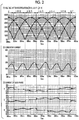
- Fig. 2 is a diagram illustrating an example of simulation waveforms of a voltage and a current in a case where a three-phase (R phase, S phase, and T phase) alternating voltage is in a balanced state.
- a simulation condition is that a frequency of the three-phase alternating voltage is 50 Hz. Further, the simulation condition is that an amplitude of the three-phase alternating voltage is 380 volts.
- Part (1) of Fig. 2 illustrates simulation waveforms of inter-line voltages (R-S voltage, S-T voltage, and T-R voltage) after rectification of the three-phase alternating voltage.
- a horizontal axis indicates time. Further, a vertical axis indicates the voltage.
- Phases of the respective simulation waveforms of the R-S voltage, the S-T voltage, and the T-R voltage are shifted from one another by 120°. Further, since the three-phase alternating voltage is in a balanced state, amplitudes of the simulation waveforms of the R-S voltage, the S-T voltage, and the T-R voltage are the same.
- Part (2) of Fig. 2 illustrates a simulation waveform of a converter current.
- a horizontal axis indicates time. Further, a vertical axis indicates the current.
- the converter current is a sum of currents corresponding to voltages after rectification of the three-phase alternating voltage, and is the current identified by the current identification part 103.
- the three-phase alternating voltage is in a balanced state, and the R-S voltage, the S-T voltage, and the T-R voltage are substantially the same. Therefore, the converter current which is a sum of currents corresponding to the voltages after rectification of the three-phase alternating voltage shows a slight fluctuation in a bias current, but shows a current fluctuation having a waveform close to a sinusoidal wave having a constant period.
- Part (3) of Fig. 2 illustrates a simulation waveform of respective currents corresponding to the R phase, the S phase, and the T phase of the three-phase alternating voltage.
- a horizontal axis indicates time. Further, a vertical axis indicates the current.
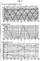
- Fig. 3 is a diagram illustrating an example of simulation waveforms of a voltage and a current in a case where the three-phase alternating voltage is in an unbalanced state.
- a simulation condition is that a frequency of the three-phase alternating voltage is 50 Hz. Further, the simulation condition is that an amplitude of the three-phase alternating voltage is 380 volts. However, in a simulation of a voltage and a current in a case where the three-phase alternating voltage is in an unbalanced state, a 3% variation is given as an unbalance rate. (Amplitudes of the S and T-phase alternating voltages are 3% larger than the amplitude of the R-phase alternating voltage.)
- Part (1) of Fig. 3 illustrates a simulation waveform of the inter-line voltage (R-S voltage, S-T voltage, and T-R voltage) after rectification of the three-phase alternating voltage.
- a horizontal axis indicates time. Further, a vertical axis indicates the voltage.
- Phases of the respective simulation waveforms of the R-S voltage, the S-T voltage, and the T-R voltage are shifted from one another by 120°. Further, the unbalance rate is 3%, and the three-phase alternating voltage is in an unbalanced state. Therefore, an amplitude of the simulation waveform of the S-T voltage is larger than the amplitudes of the respective simulation waveforms of the R-S voltage and the T-R voltage.
- Part (2) of Fig. 3 illustrates a simulation waveform of the converter current.
- a horizontal axis indicates time. Further, a vertical axis indicates the current.
- the three-phase alternating voltage is in an unbalanced state, and an amplitude of the simulation waveform of the S-T voltage is larger than the amplitudes of the simulation waveform of the R-S voltage and the T-R voltage. Therefore, a waveform of the converter current which is a sum of currents corresponding to the voltages after rectification of the three-phase alternating voltage is different from a waveform close to a sinusoidal wave having a constant period viewed in a case where the three-phase alternating voltage is in a balanced state.
- a waveform of the converter current is a waveform having a constant period, but including a period of time in which a large current flows and a period of time in which a much current does not flow. Further, a peak value of the converter current in a case where the three-phase alternating voltage is in an unbalanced state is larger than a peak value of the converter current in a case where the three-phase alternating voltage is in the balanced state.
- Part (3) of Fig. 3 illustrates simulation waveforms of the respective currents corresponding to the R phase, the S phase, and the T phase of the three-phase alternating voltage.
- a horizontal axis indicates time. Further, a vertical axis indicates the current.
- the respective currents corresponding to the R phase, the S phase, and the T phase have different current waveforms, unlike the case where the three-phase alternating voltage is in the unbalanced state.
- the period of time 1 and the period of time 4 are periods of time in which the current corresponding to the T phase of the three-phase alternating voltage does not flow as illustrated in the part (3) of Fig. 3 . Therefore, currents in period of time 1 and period of time 4 of the converter current illustrated in part (2) of Fig. 3 are currents flowing on the basis of the currents corresponding to the R phase and the S phase of the three-phase alternating voltage.
- the period of time 2 and the period of time 5 are periods of time in which the current corresponding to the S phase of the three-phase alternating voltage does not flow as illustrated in the part (3) of Fig. 3 . Therefore, currents in period of time 2 and period of time 5 of the converter current illustrated in part (2) of Fig. 3 are currents flowing on the basis of the currents corresponding to the R phase and the T phase of the three-phase alternating voltage.
- the period of time 3 and the period of time 6 are periods of time in which the current corresponding to the R phase of the three-phase alternating voltage does not flow as illustrated in the part (3) of Fig. 3 . Therefore, currents in period of time 3 and period of time 6 of the converter current illustrated in part (2) of Fig. 3 are currents flowing on the basis of the currents corresponding to the S phase and the T phase of the three-phase alternating voltage.
- the respective converter currents in the period of time 1 to the period of time 6 are currents flowing on the basis of respective currents corresponding to the R phase, the S phase, and the T phase of the three-phase alternating voltage.
- the respective converter currents in the period of time 1 to the period of time 6 have a correlation with the respective currents corresponding to the R phase, the S phase, and the T phase of the three-phase alternating voltage. It is known that if the respective currents corresponding to the R phase, the S phase, and the T phase of the three-phase alternating voltage increase, the corresponding converter currents in the period of time 1 to period of time 6 also increase. Therefore, the current estimation part 105 can estimate the currents corresponding to the R phase, the S phase, and the T phase of the three-phase alternating voltage on the basis of the converter current.
- the current estimation part 105 estimates a magnitude of the current corresponding to each phase of the three-phase alternating voltage by averaging the converter current identified by the current identification part 103 in a period of time in which the current flows.
- the current estimation part 105 estimates the current corresponding to the R phase of the three-phase alternating voltage as an average value of the converter current in (period of time 1 + period of time 2 + period of time 4 + period of time 5).
- the current estimation part 105 estimates the current corresponding to the S phase of the three-phase alternating voltage as an average value of the converter current in (period of time 1 + period of time 3 + period of time 4 + period of time 6).
- the current estimation part 105 estimates the current corresponding to the T phase of the three-phase alternating voltage as an average value of the converter current in (period of time 2 + period of time 3 + period of time 5 + period of time 6).
- the current determination part 106 determines whether or not each current estimated by the current estimation part 105 exceeds a current abnormality detection threshold value.
- the current limiting part 107 limits an upper limit of the current corresponding to the determination.
- the electric power control device 1 can detect an excessive current flowing in a case where the three-phase alternating voltage is in an unbalanced state, and protect the device.
- a process in a normal state in which the electric power control device 1 rectifies a three-phase alternating voltage to generate a DC voltage, and generates an alternating voltage for driving the motor 40 from the generated DC voltage will be described.
- Fig. 4 is a diagram illustrating an example of a process flow in a normal state of the electric power control device 1 according to this embodiment.
- the alternating power supply 10 outputs an alternating voltage of three phases (R phase, S phase, and T phase) that are shifted from one another by 120° to the AC-DC converter 20.
- the rectification part 101 receives the three-phase alternating voltage from the alternating power supply 10 (step S1). More specifically, for example, the rectification part 101 receives the R-phase alternating voltage from a connection node between the anode of the diode D1 and the cathode of the diode D2, as illustrated in Fig. 1 . The rectification part 101 receives the S-phase alternating voltage from a connection node between the anode of the diode D3 and the cathode of the diode D4. The rectification part 101 receives the T-phase alternating voltage from a connection node between the anode of the diode D5 and the cathode of the diode D6.
- the rectification part 101 performs full-wave rectification on the received three-phase alternating voltage (step S2).
- the rectification part 101 outputs the voltage after rectification to the reactor 108.
- the reactor 108 and the capacitor 109 constitute a smoothing circuit and smoothes the voltage after rectification (step S3).
- the reactor 108 and the capacitor 109 output the DC voltage after smoothing to the inverter 30.
- the inverter 30 If the inverter 30 receives the DC voltage, the inverter 30 generates an alternating voltage for driving the motor 40 from the received DC voltage (step S4). The inverter 30 outputs the generated alternating voltage to the motor 40.
- step S5 If the motor 40 receives the alternating voltage from the inverter 30, the motor 40 operates according to the received alternating voltage (step S5).
- a process in a case where the electric power control device 1 is in a normal state has been described above. In the normal state, the electric power control device 1 performs the above-described process to operate the motor 40.
- Fig. 5 is a diagram illustrating an example of a process flow for detecting an abnormal state of the electric power control device 1 according to this embodiment.
- the phase identification part 102 receives the three-phase alternating voltage from the alternating power supply 10.
- the phase identification part 102 identifies the phases of respective voltages of the R phase, the S phase, and the T phase of the received three-phase alternating voltage (step S11).
- the phase identification part 102 includes a zero cross detection circuit.
- the zero cross detection circuit included in the phase identification part 102 detects the zero cross point of the inter-line voltage R-S voltage.
- the phase identification part 102 identifies the zero cross point of the R-S voltage detected by the zero cross detection circuit as a zero cross timing of the R-S voltage.
- the phase identification part 102 identifies a timing obtained by shifting the identified zero cross timing of the R-S voltage by a timing (+1/3 period) corresponding to a phase of +120° as a zero cross timing of the S-T voltage.
- the phase identification part 102 identifies a timing obtained by shifting the identified zero cross timing of the S-T voltage by the timing corresponding to the phase of +120° as a zero cross timing of the T-R voltage.
- the zero cross detection circuit included in the phase identification part 102 may be a circuit that detects the zero cross point using the phase voltage.
- the phase identification part 102 is not limited to a phase identification part that detects one phase of the three-phase alternating voltage (a zero cross point of the R-phase alternating voltage in a case where the zero cross point is detected using the phase voltage, and a zero cross point of the R-S voltage in a case where the zero cross point is detected using the inter-line voltage).
- the zero cross detection circuit may detect two phases of the three-phase alternating voltage.
- the zero cross detection circuit may detect three phases of the three-phase alternating voltage. In the zero cross detection circuit, it is possible to reduce an influence of noise or a detection error on a phase detection result if the number of voltages of which a phase is detected in the three-phase alternating voltage increases.
- the phase identification part 102 outputs the identified phase of the voltage of each of the R phase, the S phase, and the T phase of the three-phase alternating voltage to the current identification part 103.
- the phase identification part 102 outputs the zero cross timing of each of specific inter-line voltages (R-S voltage, S-T voltage, and T-R voltage) indicating the phase of the voltage of each of the R phase, the S phase, and the T phase of the three-phase alternating voltage described with reference to Fig. 3 to the current identification part 103.
- the current identification part 103 identifies the converter current in each period of time indicated by the zero cross timing (step S12).
- a frequency of the three-phase alternating voltage is 50 Hz
- an amplitude of the three-phase alternating voltage is 380 volts
- an unbalance rate is 3% will be described as a specific example.
- the current identification part 103 identifies the converter current in each of a period of time 1 to a period of time 6 illustrated in part (2) of Fig. 3 .
- the current identification part 103 outputs a current value of the identified converter current in each of period of time 1 to period of time 6 to the microcomputer 104.
- the current estimation part 105 estimates currents corresponding to the R phase, the S phase, and the T phase of the three-phase alternating voltage on the basis of the current value of the converter current in each of period of time 1 to period of time 6 (step S13).
- the three-phase alternating voltage is in an unbalanced state and has the voltage and the current illustrated in Fig. 2 will be described as a specific example.
- the current estimation part 105 estimates the current corresponding to the R phase of the three-phase alternating voltage as an average value of the converter current in (period of time 1 + period of time 2 + period of time 4 + period of time 5).
- the current estimation part 105 estimates the current corresponding to the S phase of the three-phase alternating voltage as an average value of the converter current in (period of time 1 + period of time 3 + period of time 4 + period of time 6).
- the current estimation part 105 estimates the current corresponding to the T phase of the three-phase alternating voltage as an average value of the converter current in (period of time 2 + period of time 3 + period of time 5 + period of time 6).
- the current estimation part 105 outputs the average value of the converter current estimated for each of the R phase, the S phase, and the T phase of the three-phase alternating voltage to the current determination part 106.
- the current determination part 106 receives the average value of the converter current estimated for each of the R phase, the S phase, and the T phase of the three-phase alternating voltage from the current estimation part 105.
- the current determination part 106 compares the received average value of the converter current estimated for each of the R phase, the S phase, and the T phase with the current abnormality detection threshold value to determine whether or not each average value of the converter current exceeds the current abnormality detection threshold value (step S14).
- the current abnormality detection threshold value is a current value serving as a criterion on the basis of which the current determination part 106 determines that the electric power control device 1 is in a state different from a normal state, that is, in an abnormal state.
- the current determination part 106 determines that the electric power control device 1 is in an abnormal state.
- the current determination part 106 outputs an abnormality notification signal for notifying that the electric power control device 1 is in an abnormal state to the current limiting part 107.
- the abnormality notification signal includes information for notifying that the electric power control device 1 is in an abnormal state, and information on the average value of the converter current.
- the current limiting part 107 limits an upper limit of a current for any one of the R phase, the S phase, and the T phase corresponding to a largest average value of the converter current determined to be in an abnormal state (step S15). For example, the current limiting part 107 identifies any one of the R phase, the S phase, and the T phase corresponding to the highest average value of the converter current on the basis of the abnormality notification signal received from the current determination part 106. The current limiting part 107 limits the upper limit of the current corresponding to the alternating voltage of the identified one of the R phase, the S phase, and the T phase, to limit the upper limit of the current flowing through the inverter 30.
- the current limiting part 107 changes a threshold value of a window comparator that determines an upper limit of a current, which is arranged in a stage before the inverter 30, to limit the upper limit of the current flowing through the inverter 30.
- Limiting the upper limit of the current flowing through the inverter 30 includes setting the upper limit of the current to zero. Further, limiting the upper limit of the current flowing through the inverter 30 also includes stopping the electric power control device 1.
- the inverter 30 receives a DC voltage corresponding to the current of which the upper limit has been limited from the smoothing circuit including the reactor 108 and the capacitor 109.
- the inverter 30 generates an alternating voltage for driving the motor 40 from the DC voltage corresponding to the current of which the upper limit has been limited (step S16).
- the inverter 30 outputs the generated alternating voltage to the motor 40.
- step S17 If the motor 40 receives the alternating voltage from the inverter 30, the motor 40 operates according to the received alternating voltage (step S17). The process returns to step S11.
- the current determination part 106 determines that the electric power control device 1 is in a normal state. In this case, the current limiting part 107 releases the upper limit of the current that has been limited (step S18). The process returns to step S11.
- the phase identification part 102 identifies the phases of respective voltages of the R phase, the S phase, and the T phase of the received three-phase alternating voltage. If the current identification part 103 receives the zero cross timing from the phase identification part 102, the current identification part 103 identifies the converter currents corresponding to the respective voltages of the R phase, the S phase, and the T phase of the three-phase alternating voltage in each period of time indicated by the zero cross timing.
- the current estimation circuit 111 is not limited to the application to the electric power control device 1 described in this embodiment.
- the current estimation circuit 111 may be applied to the electric power control device 1 including a pulse amplitude modulation (PAM) circuit.
- the current estimation circuit 111 may be applied to an electric power control device 1 including an active converter using a transistor or the like. Further, the current estimation circuit 111 may be applied to an electric power control device 1 including an active filter.
- PAM pulse amplitude modulation
- the current identification part 103 may detect the converter current on the basis of a current detected by a current sensor such as a current transformer arranged in place of the current detection resistor 110.
- the process flow of the electric power control device 1 has been described using the process for the three-phase alternating voltage as an example, the process flow is not limited thereto.
- the process flow of the electric power control device 1 may be a process for a two-phase alternating voltage and a four or more-phase alternating voltage.
- the phase difference between the respective voltages is different from a phase difference 120° of the three-phase alternating voltage.
- a processing order may be interchanged in a range in which an appropriate process is performed.
- the current estimation circuit 111 included in the electric power control device 1 described above includes a computer system therein.
- the above-described processes of the steps are stored in the form of a program in a computer-readable recording medium, and this program is read and executed by the computer to perform the above process.
- the computer-readable recording medium refers to a magnetic disk, a magnetooptical disc, a CD-ROM, a DVD-ROM, a semiconductor memory, or the like.
- this computer program may be distributed via a communication line, and the computer receiving this distribution may execute the program.
- the above program may realize some of the above-described functions.
- the program may be a file capable of realizing the above-described functions in combination with a program previously stored in a computer system, a so-called differential file (a differential program).
- the current estimation circuit for a rectification circuit the AC-DC converter, the electric power control device, the current estimation circuit, and the method and the program for current estimation described above, it is possible to easily detect an abnormal state in a system and protect the system in a case where respective voltages of the R phase, the S phase, and the T phase of the three-phase alternating power supply enter the unbalanced state.
- Reference Signs List
Landscapes
- Engineering & Computer Science (AREA)
- Power Engineering (AREA)
- Rectifiers (AREA)
- Inverter Devices (AREA)
Abstract
Description
- The present invention relates to a current estimation circuit for a rectification circuit, an AC-DC converter, an electric power control device, a current estimation circuit, and a method and program for current estimation.
- Priority is claimed on Japanese Patent Application No.
2014-212667, filed October 17, 2014 - There is a system that generates a voltage to drive a motor on the basis of an alternating voltage that is supplied from a three-phase alternating power supply. Generally, the system that generates a voltage to drive a motor includes an AC-DC converter and an inverter. In this system, the AC-DC converter converts the alternating voltage supplied from the three-phase alternating power supply from the alternating voltage into a DC voltage, and the inverter converts the DC voltage converted by the AC-DC converter into an alternating voltage. By doing so, the system generates a DC voltage suitable for driving of the motor.
- Related art is disclosed in
PTL 1. A device disclosed inPTL 1 includes a pulse width modulation (PWM) rectification circuit and a PWM inverter. This device determines whether or not there is an abnormality in a supply voltage for the PWM rectification circuit on the basis of a current. This device decreases an output frequency or a duty of the PWM inverter in a case where it is determined that there is an abnormality, to thereby protect the circuit. - [PTL 1] Japanese Patent No.
4759968 - If respective voltages of an R phase, an S phase, and a T phase of a three-phase alternating power supply enter an unbalanced state in a system that generates a voltage to drive a general motor, an excessive current may flow into a device to which an electric power is supplied from the three-phase alternating power supply or a device connected to a stage subsequent to such a device. In this case, a malfunction is likely to occur in the system.
- Therefore, a technology capable of easily detecting an abnormal state in a system and protecting the system in a case where the respective voltages of the R phase, the S phase, and the T phase of the three-phase alternating power supply enter an unbalanced state, is required.
- An object of the present invention is to provide a current estimation circuit for a rectification circuit, an AC-DC converter, an electric power control device, a current estimation circuit, and a method and program for current estimation capable of solving the above problem.
- According to a first aspect of the present invention, a current estimation circuit for a rectification circuit includes a phase identification part that identifies respective phases of a plurality of alternating voltages that are output from a power supply; and a current identification part that identifies currents corresponding to voltages after rectification of the plurality of alternating voltages at time intervals determined on the basis of the respective phases identified by the phase identification part.
- According to a second aspect of the present invention, in the current estimation circuit for a rectification circuit in the first aspect, the current identification part may identify the currents corresponding to the voltages after rectification on the basis of a current flowing through a resistor after the rectification.
- According to a third aspect of the present invention, in the current estimation circuit for a rectification circuit in the first aspect, the current identification part may identify the currents corresponding to the voltages after rectification on the basis of a current detected by a current transformer after the rectification.
- According to a fourth aspect of the present invention, the current estimation circuit for a rectification circuit in any one of the first to third aspects may further include a current estimation part that estimates respective currents corresponding to the plurality of alternating voltages on the basis of the currents corresponding to the voltages after rectification identified by the current identification part.
- According to a fifth aspect of the present invention, the current estimation circuit for a rectification circuit in the fourth aspect may further include a current determination part that determines whether or not each of the currents estimated by the current estimation part exceeds a current abnormality detection threshold value; and a current limiting part that limits an upper limit of the respective estimated currents corresponding to the determination in a case where the current determination part determines that the respective estimated currents exceed the current abnormality detection threshold value.
- According to a sixth aspect of the present invention, an AC-DC converter includes the current estimation circuit for a rectification circuit in any one of the first to fifth aspects; and a smoothing circuit that smoothes a voltage output by the rectification circuit.
- According to a seventh aspect of the present invention, an electric power control device includes the AC-DC converter in the sixth aspect; and an inverter that converts a DC voltage output by the AC-DC converter into an alternating voltage.
- According to an eighth aspect of the present invention, a current estimation circuit includes a current estimation part that estimates respective currents corresponding to a plurality of alternating voltages output from a power supply on the basis of currents corresponding to voltages after rectification of the plurality of alternating voltages at time intervals determined on the basis of respective phases of the plurality of alternating voltages.
- According to a ninth aspect of the present invention, the current estimation circuit in the eighth aspect may further include a current determination part that determines whether or not each of the currents estimated by the current estimation part exceeds a current abnormality detection threshold value; and a current limiting part that limits an upper limit of the respective estimated currents corresponding to the determination in a case where the current determination part determines that the respective estimated currents exceed the current abnormality detection threshold value.
- According to a tenth aspect of the present invention, a current estimation method includes identifying respective phases of a plurality of alternating voltages that are output from a power supply; and identifying currents corresponding to voltages after rectification of the plurality of alternating voltages at time intervals determined on the basis of the respective identified phases.
- According to an eleventh aspect of the present invention, a current estimation method includes estimating respective currents corresponding to a plurality of alternating voltages output from a power supply on the basis of currents corresponding to voltages after rectification of the plurality of alternating voltages at time intervals determined on the basis of respective phases of the plurality of alternating voltages.
- According to a twelfth aspect of the present invention, a program causes a computer to execute estimating respective currents corresponding to a plurality of alternating voltages output from a power supply on the basis of currents corresponding to voltages after rectification of the plurality of alternating voltages at time intervals determined on the basis of respective phases of the plurality of alternating voltages. Advantageous Effects of Invention
- According to the current estimation circuit for a rectification circuit, the AC-DC converter, the electric power control device, the current estimation circuit, and the method and the program for current estimation, it is possible to easily detect an abnormal state in a system and protect the system in a case where respective voltages of the R phase, the S phase, and the T phase of the three-phase alternating power supply enter an unbalanced state. Brief Description of Drawings
-
-
Fig. 1 is a diagram illustrating an example of a configuration of an electric power control device including a rectification circuit according to an embodiment of the present invention. -
Fig. 2 is a diagram illustrating an example of simulation waveforms of voltages and currents in a case where a three-phase (R phase, S phase, and T phase) alternating voltage is in a balanced state in the embodiment. -
Fig. 3 is a diagram illustrating an example of simulation waveforms of voltages and currents in a case where a three-phase alternating voltage is in an unbalanced state in the embodiment. -
Fig. 4 is a diagram illustrating an example of a process flow in a normal state of the electric power control device according to the embodiment. -
Fig. 5 is a diagram illustrating an example of a process flow for detecting an abnormal state of the electric power control device according to the embodiment. -
Fig. 6 is a diagram illustrating an example of a configuration of an electric power control device including a PAM circuit according to the embodiment. -
Fig. 7 is a diagram illustrating an example of a configuration of an electric power control device including an active converter according to the embodiment. - Hereinafter, embodiments will be described in detail with reference to the drawings.
- First, a configuration of an electric
power control device 1 including arectification circuit 100 according to this embodiment will be described. -
Fig. 1 is a diagram illustrating an example of a configuration of the electricpower control device 1 including arectification circuit 100 according to an embodiment of the present invention. - As illustrated in
Fig. 1 , the electricpower control device 1 according to this embodiment includes analternating power supply 10, an AC (Alternative Current)-DC (Direct Current)converter 20, aninverter 30, and amotor 40. - The alternating power supply 10 outputs a plurality of alternating voltages. For example, the alternating power supply 10 outputs three sinusoidal alternating voltages (R phase, S phase, and T phase) of which phases are mutually shifted by 120° to a
rectification part 101. - The AC-
DC converter 20 includes arectification circuit 100, areactor 108, and acapacitor 109. - The
rectification circuit 100 includes therectification part 101, acurrent detection resistor 110, and acurrent estimation circuit 111. - The
rectification part 101 rectifies the alternating voltage output from thealternating power supply 10. For example, therectification part 101 includes six diodes D1 to D6. An anode of the diode D1 is connected to a cathode of the diode D2. An anode of the diode D3 is connected to a cathode of the diode D4. An anode of the diode D5 is connected to a cathode of the diode D6. Thealternating power supply 10 outputs an R-phase alternating voltage to the anode of the diode D1. Thealternating power supply 10 outputs an S-phase alternating voltage to the anode of the diode D3. The alternating power supply 10 outputs a T-phase alternating voltage to the anode of the diode D5. Therectification part 101 performs full-wave rectification on the alternating voltage that the alternating power supply 10 outputs to therectification part 101. - The
current detection resistor 110 is a resistor that detects a converter current flowing through the AC-DC converter 20. - The
current estimation circuit 111 includes aphase identification part 102, acurrent identification part 103, and amicrocomputer 104. - The
phase identification part 102 identifies each phase of the plurality of alternating voltages output from thealternating power supply 10. For example, thephase identification part 102 includes a zero cross detection circuit. The zero cross detection circuit included in thephase identification part 102 detects a zero cross point using an inter-line voltage or a phase voltage. The zero cross point is a point at which a bias voltage indicating a zero amplitude of the alternating voltage crosses the alternating voltage. - For example, in a case where the zero cross point is detected using the phase voltage, the zero cross detection circuit included in the
phase identification part 102 detects a zero cross point of the R-phase alternating voltage. Thephase identification part 102 identifies a zero cross timing of the R-phase alternating voltage on the basis of the zero cross point of the R-phase alternating voltage detected by the zero cross detection circuit. Thephase identification part 102 identifies a timing obtained by shifting the identified zero cross timing of the R-phase alternating voltage by a timing (+1/3 period) corresponding to the phase of +120° as a zero cross timing of the S-phase alternating voltage. Thephase identification part 102 identifies a timing obtained by shifting the identified zero cross timing of the S-phase alternating voltage by a timing corresponding to the phase of +120° as a zero cross timing of the T-phase alternating voltage. - For example, in a case where the zero cross point is detected using the inter-line voltage, the zero cross detection circuit included in the
phase identification part 102 detects a zero cross point of the R-S voltage. Thephase identification part 102 identifies a zero cross timing of the R-S voltage on the basis of the zero cross point of the R-S voltage detected by the zero cross detection circuit. Thephase identification part 102 identifies a timing obtained by shifting the identified zero cross timing of the R-S voltage by a timing (+1/3 period) corresponding to a phase of +120° as a zero cross timing of the S-T voltage. Thephase identification part 102 identifies a timing obtained by shifting the identified zero cross timing of the S-T voltage by the timing corresponding to the phase of +120° as a zero cross timing of the T-R voltage. - The zero cross detection circuit included in the
phase identification part 102 is not limited to a circuit that detects one phase of the three-phase alternating voltage (a zero cross point of the R-phase alternating voltage in a case where the zero cross point is detected using the phase voltage, and a zero cross point of the R-S voltage in a case where the zero cross point is detected using the inter-line voltage). For example, the zero cross detection circuit included in thephase identification part 102 may detect two phases of the three-phase alternating voltage. Further, the zero cross detection circuit may detect three phases of the three-phase alternating voltage. In the zero cross detection circuit included in thephase identification part 102, it is possible to reduce an influence of noise or a detection error on a phase detection result if the number of voltages of which a phase is detected in the three-phase alternating voltage increases. - The
current identification part 103 identifies a current corresponding to a voltage after rectification of a plurality of alternating voltages at time intervals of the zero cross timing determined on the basis of each phase of the plurality of alternating voltages identified by thephase identification part 102. For example, thecurrent identification part 103 acquires a voltage generated across a resistor arranged in stage subsequent to therectification circuit 100. Thecurrent identification part 103 calculates a current by dividing the acquired voltage by a resistance value of the resistor. Further, for example, thecurrent identification part 103 divides a voltage across thecurrent detection resistor 110 arranged in a stage subsequent to therectification circuit 100 by a resistance value to acquire a current. - The
microcomputer 104 includes acurrent estimation part 105, acurrent determination part 106, and a current limitingpart 107. - The
current estimation part 105 estimates a current corresponding to each of the plurality of alternating voltages on the basis of the current corresponding to the voltage after rectification of the plurality of alternating voltages identified by thecurrent identification part 103. - The
current determination part 106 determines whether or not each current estimated by thecurrent estimation part 105 exceeds a current abnormality detection threshold value. The current abnormality detection threshold value is a current value serving as a criterion on the basis of which thecurrent determination part 106 determines that the electricpower control device 1 is in a state different from a normal state if a current higher than the current abnormality detection threshold value flows. The current abnormality detection threshold value may be determined by circuit simulation, for example. - In a case where the
current determination part 106 determines that the current exceeds the current abnormality detection threshold value, the current limitingpart 107 limits an upper limit of the current corresponding to the determination. - The
reactor 108 and thecapacitor 109 constitute a smoothing circuit. This smoothing circuit smoothes the voltage output by therectification circuit 100. - The
inverter 30 converts a DC voltage output by the AC-DC converter 20 into an alternating voltage. For example, theinverter 30 is an inverter configured with an Insulated Gate Bipolar Transistor (IGBT). - The
motor 40 operates according to the alternating voltage output by theinverter 30. - Next, full-wave rectification of the alternating voltage that is performed by the
rectification circuit 100 will be described. -
Fig. 2 is a diagram illustrating an example of simulation waveforms of a voltage and a current in a case where a three-phase (R phase, S phase, and T phase) alternating voltage is in a balanced state. - A simulation condition is that a frequency of the three-phase alternating voltage is 50 Hz. Further, the simulation condition is that an amplitude of the three-phase alternating voltage is 380 volts.
- Part (1) of
Fig. 2 illustrates simulation waveforms of inter-line voltages (R-S voltage, S-T voltage, and T-R voltage) after rectification of the three-phase alternating voltage. A horizontal axis indicates time. Further, a vertical axis indicates the voltage. - Phases of the respective simulation waveforms of the R-S voltage, the S-T voltage, and the T-R voltage are shifted from one another by 120°. Further, since the three-phase alternating voltage is in a balanced state, amplitudes of the simulation waveforms of the R-S voltage, the S-T voltage, and the T-R voltage are the same.
- Part (2) of
Fig. 2 illustrates a simulation waveform of a converter current. A horizontal axis indicates time. Further, a vertical axis indicates the current. - The converter current is a sum of currents corresponding to voltages after rectification of the three-phase alternating voltage, and is the current identified by the
current identification part 103. - The three-phase alternating voltage is in a balanced state, and the R-S voltage, the S-T voltage, and the T-R voltage are substantially the same. Therefore, the converter current which is a sum of currents corresponding to the voltages after rectification of the three-phase alternating voltage shows a slight fluctuation in a bias current, but shows a current fluctuation having a waveform close to a sinusoidal wave having a constant period.
- Part (3) of
Fig. 2 illustrates a simulation waveform of respective currents corresponding to the R phase, the S phase, and the T phase of the three-phase alternating voltage. A horizontal axis indicates time. Further, a vertical axis indicates the current. - Since the three-phase alternating voltage is in balanced state, phases of the respective currents corresponding to the R phase, the S phase, and the T phase are shifted from one another by 120°, but the respective current waveforms are substantially the same.
-
Fig. 3 is a diagram illustrating an example of simulation waveforms of a voltage and a current in a case where the three-phase alternating voltage is in an unbalanced state. - A simulation condition is that a frequency of the three-phase alternating voltage is 50 Hz. Further, the simulation condition is that an amplitude of the three-phase alternating voltage is 380 volts. However, in a simulation of a voltage and a current in a case where the three-phase alternating voltage is in an unbalanced state, a 3% variation is given as an unbalance rate. (Amplitudes of the S and T-phase alternating voltages are 3% larger than the amplitude of the R-phase alternating voltage.)
- Part (1) of
Fig. 3 illustrates a simulation waveform of the inter-line voltage (R-S voltage, S-T voltage, and T-R voltage) after rectification of the three-phase alternating voltage. A horizontal axis indicates time. Further, a vertical axis indicates the voltage. - Phases of the respective simulation waveforms of the R-S voltage, the S-T voltage, and the T-R voltage are shifted from one another by 120°. Further, the unbalance rate is 3%, and the three-phase alternating voltage is in an unbalanced state. Therefore, an amplitude of the simulation waveform of the S-T voltage is larger than the amplitudes of the respective simulation waveforms of the R-S voltage and the T-R voltage.
- Part (2) of
Fig. 3 illustrates a simulation waveform of the converter current. A horizontal axis indicates time. Further, a vertical axis indicates the current. - The three-phase alternating voltage is in an unbalanced state, and an amplitude of the simulation waveform of the S-T voltage is larger than the amplitudes of the simulation waveform of the R-S voltage and the T-R voltage. Therefore, a waveform of the converter current which is a sum of currents corresponding to the voltages after rectification of the three-phase alternating voltage is different from a waveform close to a sinusoidal wave having a constant period viewed in a case where the three-phase alternating voltage is in a balanced state. A waveform of the converter current is a waveform having a constant period, but including a period of time in which a large current flows and a period of time in which a much current does not flow. Further, a peak value of the converter current in a case where the three-phase alternating voltage is in an unbalanced state is larger than a peak value of the converter current in a case where the three-phase alternating voltage is in the balanced state.
- Part (3) of
Fig. 3 illustrates simulation waveforms of the respective currents corresponding to the R phase, the S phase, and the T phase of the three-phase alternating voltage. A horizontal axis indicates time. Further, a vertical axis indicates the current. - Since the three-phase alternating voltage is in an unbalanced state, the respective currents corresponding to the R phase, the S phase, and the T phase have different current waveforms, unlike the case where the three-phase alternating voltage is in the unbalanced state.
- As illustrated in
Fig. 3 , attention is paid to part (2) ofFig. 3 and part (3) ofFig. 3 which are divided into period oftime 1 to period oftime 6. - The period of
time 1 and the period oftime 4 are periods of time in which the current corresponding to the T phase of the three-phase alternating voltage does not flow as illustrated in the part (3) ofFig. 3 . Therefore, currents in period oftime 1 and period oftime 4 of the converter current illustrated in part (2) ofFig. 3 are currents flowing on the basis of the currents corresponding to the R phase and the S phase of the three-phase alternating voltage. - The period of
time 2 and the period oftime 5 are periods of time in which the current corresponding to the S phase of the three-phase alternating voltage does not flow as illustrated in the part (3) ofFig. 3 . Therefore, currents in period oftime 2 and period oftime 5 of the converter current illustrated in part (2) ofFig. 3 are currents flowing on the basis of the currents corresponding to the R phase and the T phase of the three-phase alternating voltage. - The period of
time 3 and the period oftime 6 are periods of time in which the current corresponding to the R phase of the three-phase alternating voltage does not flow as illustrated in the part (3) ofFig. 3 . Therefore, currents in period oftime 3 and period oftime 6 of the converter current illustrated in part (2) ofFig. 3 are currents flowing on the basis of the currents corresponding to the S phase and the T phase of the three-phase alternating voltage. - Therefore, the respective converter currents in the period of
time 1 to the period oftime 6 are currents flowing on the basis of respective currents corresponding to the R phase, the S phase, and the T phase of the three-phase alternating voltage. The respective converter currents in the period oftime 1 to the period oftime 6 have a correlation with the respective currents corresponding to the R phase, the S phase, and the T phase of the three-phase alternating voltage. It is known that if the respective currents corresponding to the R phase, the S phase, and the T phase of the three-phase alternating voltage increase, the corresponding converter currents in the period oftime 1 to period oftime 6 also increase. Therefore, thecurrent estimation part 105 can estimate the currents corresponding to the R phase, the S phase, and the T phase of the three-phase alternating voltage on the basis of the converter current. - More specifically, the
current estimation part 105 estimates a magnitude of the current corresponding to each phase of the three-phase alternating voltage by averaging the converter current identified by thecurrent identification part 103 in a period of time in which the current flows. A case where the three-phase alternating voltage is in an unbalanced state and has the voltage and the current illustrated inFig. 3 will be described as a specific example. In this case, thecurrent estimation part 105 estimates the current corresponding to the R phase of the three-phase alternating voltage as an average value of the converter current in (period oftime 1 + period oftime 2 + period oftime 4 + period of time 5). Thecurrent estimation part 105 estimates the current corresponding to the S phase of the three-phase alternating voltage as an average value of the converter current in (period oftime 1 + period oftime 3 + period oftime 4 + period of time 6). Thecurrent estimation part 105 estimates the current corresponding to the T phase of the three-phase alternating voltage as an average value of the converter current in (period oftime 2 + period oftime 3 + period oftime 5 + period of time 6). - The
current determination part 106 determines whether or not each current estimated by thecurrent estimation part 105 exceeds a current abnormality detection threshold value. - In a case where the
current determination part 106 determines that the current exceeds the current abnormality detection threshold value, the current limitingpart 107 limits an upper limit of the current corresponding to the determination. - By doing so, the electric
power control device 1 can detect an excessive current flowing in a case where the three-phase alternating voltage is in an unbalanced state, and protect the device. - Next, a process that is performed by the electric
power control device 1 according to this embodiment will be described. - Here, the process will be described, for example, in the electric
power control device 1 illustrated inFig. 1 . - A process in a normal state in which the electric
power control device 1 rectifies a three-phase alternating voltage to generate a DC voltage, and generates an alternating voltage for driving themotor 40 from the generated DC voltage will be described. -
Fig. 4 is a diagram illustrating an example of a process flow in a normal state of the electricpower control device 1 according to this embodiment. - The alternating
power supply 10 outputs an alternating voltage of three phases (R phase, S phase, and T phase) that are shifted from one another by 120° to the AC-DC converter 20. - If the AC-
DC converter 20 receives the three-phase alternating voltage from the alternatingpower supply 10, therectification part 101 receives the three-phase alternating voltage from the alternating power supply 10 (step S1). More specifically, for example, therectification part 101 receives the R-phase alternating voltage from a connection node between the anode of the diode D1 and the cathode of the diode D2, as illustrated inFig. 1 . Therectification part 101 receives the S-phase alternating voltage from a connection node between the anode of the diode D3 and the cathode of the diode D4. Therectification part 101 receives the T-phase alternating voltage from a connection node between the anode of the diode D5 and the cathode of the diode D6. - The
rectification part 101 performs full-wave rectification on the received three-phase alternating voltage (step S2). Therectification part 101 outputs the voltage after rectification to thereactor 108. - The
reactor 108 and thecapacitor 109 constitute a smoothing circuit and smoothes the voltage after rectification (step S3). Thereactor 108 and thecapacitor 109 output the DC voltage after smoothing to theinverter 30. - If the
inverter 30 receives the DC voltage, theinverter 30 generates an alternating voltage for driving themotor 40 from the received DC voltage (step S4). Theinverter 30 outputs the generated alternating voltage to themotor 40. - If the
motor 40 receives the alternating voltage from theinverter 30, themotor 40 operates according to the received alternating voltage (step S5). - A process in a case where the electric
power control device 1 is in a normal state has been described above. In the normal state, the electricpower control device 1 performs the above-described process to operate themotor 40. - Next, a process of detecting an abnormal state that the electric
power control device 1 performs in parallel with the process in the normal state will be described. -
Fig. 5 is a diagram illustrating an example of a process flow for detecting an abnormal state of the electricpower control device 1 according to this embodiment. - If the AC-
DC converter 20 receives the three-phase alternating voltage from the alternatingpower supply 10, thephase identification part 102 receives the three-phase alternating voltage from the alternatingpower supply 10. - The
phase identification part 102 identifies the phases of respective voltages of the R phase, the S phase, and the T phase of the received three-phase alternating voltage (step S11). For example, thephase identification part 102 includes a zero cross detection circuit. The zero cross detection circuit included in thephase identification part 102 detects the zero cross point of the inter-line voltage R-S voltage. Thephase identification part 102 identifies the zero cross point of the R-S voltage detected by the zero cross detection circuit as a zero cross timing of the R-S voltage. Thephase identification part 102 identifies a timing obtained by shifting the identified zero cross timing of the R-S voltage by a timing (+1/3 period) corresponding to a phase of +120° as a zero cross timing of the S-T voltage. Thephase identification part 102 identifies a timing obtained by shifting the identified zero cross timing of the S-T voltage by the timing corresponding to the phase of +120° as a zero cross timing of the T-R voltage. The zero cross detection circuit included in thephase identification part 102 may be a circuit that detects the zero cross point using the phase voltage. - The
phase identification part 102 is not limited to a phase identification part that detects one phase of the three-phase alternating voltage (a zero cross point of the R-phase alternating voltage in a case where the zero cross point is detected using the phase voltage, and a zero cross point of the R-S voltage in a case where the zero cross point is detected using the inter-line voltage). For example, the zero cross detection circuit may detect two phases of the three-phase alternating voltage. Further, the zero cross detection circuit may detect three phases of the three-phase alternating voltage. In the zero cross detection circuit, it is possible to reduce an influence of noise or a detection error on a phase detection result if the number of voltages of which a phase is detected in the three-phase alternating voltage increases. - The
phase identification part 102 outputs the identified phase of the voltage of each of the R phase, the S phase, and the T phase of the three-phase alternating voltage to thecurrent identification part 103. For example, thephase identification part 102 outputs the zero cross timing of each of specific inter-line voltages (R-S voltage, S-T voltage, and T-R voltage) indicating the phase of the voltage of each of the R phase, the S phase, and the T phase of the three-phase alternating voltage described with reference toFig. 3 to thecurrent identification part 103. - If the
current identification part 103 receives the zero cross timing fromphase identification part 102, thecurrent identification part 103 identifies the converter current in each period of time indicated by the zero cross timing (step S12). A case where a frequency of the three-phase alternating voltage is 50 Hz, an amplitude of the three-phase alternating voltage is 380 volts, and an unbalance rate is 3% will be described as a specific example. In this case, thecurrent identification part 103 identifies the converter current in each of a period oftime 1 to a period oftime 6 illustrated in part (2) ofFig. 3 . Thecurrent identification part 103 outputs a current value of the identified converter current in each of period oftime 1 to period oftime 6 to themicrocomputer 104. - If the
microcomputer 104 receives the current value of the converter current in each of period oftime 1 to period oftime 6 from thecurrent identification part 103, thecurrent estimation part 105 estimates currents corresponding to the R phase, the S phase, and the T phase of the three-phase alternating voltage on the basis of the current value of the converter current in each of period oftime 1 to period of time 6 (step S13). A case where the three-phase alternating voltage is in an unbalanced state and has the voltage and the current illustrated inFig. 2 will be described as a specific example. In this case, thecurrent estimation part 105 estimates the current corresponding to the R phase of the three-phase alternating voltage as an average value of the converter current in (period oftime 1 + period oftime 2 + period oftime 4 + period of time 5). Thecurrent estimation part 105 estimates the current corresponding to the S phase of the three-phase alternating voltage as an average value of the converter current in (period oftime 1 + period oftime 3 + period oftime 4 + period of time 6). Thecurrent estimation part 105 estimates the current corresponding to the T phase of the three-phase alternating voltage as an average value of the converter current in (period oftime 2 + period oftime 3 + period oftime 5 + period of time 6). - The
current estimation part 105 outputs the average value of the converter current estimated for each of the R phase, the S phase, and the T phase of the three-phase alternating voltage to thecurrent determination part 106. - The
current determination part 106 receives the average value of the converter current estimated for each of the R phase, the S phase, and the T phase of the three-phase alternating voltage from thecurrent estimation part 105. Thecurrent determination part 106 compares the received average value of the converter current estimated for each of the R phase, the S phase, and the T phase with the current abnormality detection threshold value to determine whether or not each average value of the converter current exceeds the current abnormality detection threshold value (step S14). The current abnormality detection threshold value is a current value serving as a criterion on the basis of which thecurrent determination part 106 determines that the electricpower control device 1 is in a state different from a normal state, that is, in an abnormal state. - In a case where the average value of the converter current exceeds the current abnormality detection threshold value (YES in step S14), the
current determination part 106 determines that the electricpower control device 1 is in an abnormal state. Thecurrent determination part 106 outputs an abnormality notification signal for notifying that the electricpower control device 1 is in an abnormal state to the current limitingpart 107. The abnormality notification signal includes information for notifying that the electricpower control device 1 is in an abnormal state, and information on the average value of the converter current. - If the current limiting
part 107 receives the abnormality notification signal from thecurrent determination part 106, the current limitingpart 107 limits an upper limit of a current for any one of the R phase, the S phase, and the T phase corresponding to a largest average value of the converter current determined to be in an abnormal state (step S15). For example, the current limitingpart 107 identifies any one of the R phase, the S phase, and the T phase corresponding to the highest average value of the converter current on the basis of the abnormality notification signal received from thecurrent determination part 106. The current limitingpart 107 limits the upper limit of the current corresponding to the alternating voltage of the identified one of the R phase, the S phase, and the T phase, to limit the upper limit of the current flowing through theinverter 30. For example, the current limitingpart 107 changes a threshold value of a window comparator that determines an upper limit of a current, which is arranged in a stage before theinverter 30, to limit the upper limit of the current flowing through theinverter 30. Limiting the upper limit of the current flowing through theinverter 30 includes setting the upper limit of the current to zero. Further, limiting the upper limit of the current flowing through theinverter 30 also includes stopping the electricpower control device 1. - The
inverter 30 receives a DC voltage corresponding to the current of which the upper limit has been limited from the smoothing circuit including thereactor 108 and thecapacitor 109. Theinverter 30 generates an alternating voltage for driving themotor 40 from the DC voltage corresponding to the current of which the upper limit has been limited (step S16). Theinverter 30 outputs the generated alternating voltage to themotor 40. - If the
motor 40 receives the alternating voltage from theinverter 30, themotor 40 operates according to the received alternating voltage (step S17). The process returns to step S11. - In a case where the average value of the converter current is lower than or equal to the current abnormality detection threshold value (NO in step S14), the
current determination part 106 determines that the electricpower control device 1 is in a normal state. In this case, the current limitingpart 107 releases the upper limit of the current that has been limited (step S18). The process returns to step S11. - The process flow of the electric
power control device 1 according to an embodiment of the present invention has been described above. In the process of the electricpower control device 1 described above, thephase identification part 102 identifies the phases of respective voltages of the R phase, the S phase, and the T phase of the received three-phase alternating voltage. If thecurrent identification part 103 receives the zero cross timing from thephase identification part 102, thecurrent identification part 103 identifies the converter currents corresponding to the respective voltages of the R phase, the S phase, and the T phase of the three-phase alternating voltage in each period of time indicated by the zero cross timing. - Thus, it is possible to easily detect an abnormal state in the electric power control device 1 (system) and protect the electric
power control device 1 on the basis of the estimated currents corresponding to the respective voltages of the R phase, the S phase, and the T phase in a case where respective voltages of the R phase, the S phase, and the T phase of the three-phase alternating power supply enter an unbalanced state.. - The
current estimation circuit 111 according to an embodiment of the present invention is not limited to the application to the electricpower control device 1 described in this embodiment. For example, as illustrated inFig. 6 , thecurrent estimation circuit 111 may be applied to the electricpower control device 1 including a pulse amplitude modulation (PAM) circuit. Further, as illustrated inFig. 7 , thecurrent estimation circuit 111 may be applied to an electricpower control device 1 including an active converter using a transistor or the like. Further, thecurrent estimation circuit 111 may be applied to an electricpower control device 1 including an active filter. - The
current identification part 103 according to an embodiment of the present invention may detect the converter current on the basis of a current detected by a current sensor such as a current transformer arranged in place of thecurrent detection resistor 110. - The process flow of the electric
power control device 1 according to an embodiment of the present invention has been described using the process for the three-phase alternating voltage as an example, the process flow is not limited thereto. For example, the process flow of the electricpower control device 1 may be a process for a two-phase alternating voltage and a four or more-phase alternating voltage. However, in a case where the electricpower control device 1 performs the process for the two-phase alternating voltage or a four or more-phase alternating voltage, the phase difference between the respective voltages is different from a phase difference 120° of the three-phase alternating voltage. - In the process flow in an embodiment of the present invention, a processing order may be interchanged in a range in which an appropriate process is performed.
- Although the embodiments of the present invention have been described, the
current estimation circuit 111 included in the electricpower control device 1 described above includes a computer system therein. The above-described processes of the steps are stored in the form of a program in a computer-readable recording medium, and this program is read and executed by the computer to perform the above process. Here, the computer-readable recording medium refers to a magnetic disk, a magnetooptical disc, a CD-ROM, a DVD-ROM, a semiconductor memory, or the like. Further, this computer program may be distributed via a communication line, and the computer receiving this distribution may execute the program. - Further, the above program may realize some of the above-described functions. Further, the program may be a file capable of realizing the above-described functions in combination with a program previously stored in a computer system, a so-called differential file (a differential program).
- Several embodiments of the present invention have been described, but the embodiments are examples and do not limit the scope of the invention. Various omissions, substitutions, and changes may be made for the embodiments without departing from the scope of the invention.
- According to the current estimation circuit for a rectification circuit, the AC-DC converter, the electric power control device, the current estimation circuit, and the method and the program for current estimation described above, it is possible to easily detect an abnormal state in a system and protect the system in a case where respective voltages of the R phase, the S phase, and the T phase of the three-phase alternating power supply enter the unbalanced state. Reference Signs List
-
- 1: electric power control device
- 10: alternating power supply
- 20: AC-DC converter
- 30: inverter
- 40: motor
- 100: rectification circuit
- 101: rectification part
- 102: phase identification part
- 103: current identification part
- 104: microcomputer
- 105: current estimation part
- 106: current determination part
- 107: current limiting part
- 108, 108a, 108b, 108c: reactor
- 109: capacitor
- 110: current detection resistor
- 111: current estimation circuit
- D1, D2, D3, D4, D5, D6: diode
Claims (12)
- A current estimation circuit for a rectification circuit, the current estimation circuit comprising:a phase identification part that identifies respective phases of a plurality of alternating voltages that are output from a power supply; anda current identification part that identifies currents corresponding to voltages after rectification of the plurality of alternating voltages at time intervals determined on the basis of the respective phases identified by the phase identification part.
- The current estimation circuit for a rectification circuit according to claim 1,
wherein the current identification part identifies the currents corresponding to the voltages after rectification on the basis of a current flowing through a resistor after the rectification. - The current estimation circuit for a rectification circuit according to claim 1,
wherein the current identification part identifies the currents corresponding to the voltages after rectification on the basis of a current detected by a current transformer after the rectification. - The current estimation circuit for a rectification circuit according to any one of claims 1 to 3, further comprising:a current estimation part that estimates respective currents corresponding to the plurality of alternating voltages on the basis of the currents corresponding to the voltages after rectification identified by the current identification part.
- The current estimation circuit for a rectification circuit according to claim 4, further comprising:a current determination part that determines whether or not each of the currents estimated by the current estimation part exceeds a current abnormality detection threshold value; anda current limiting part that limits an upper limit of the respective estimated currents corresponding to the determination in a case where the current determination part determines that the respective estimated currents exceed the current abnormality detection threshold value.
- An AC-DC converter, comprising:the current estimation circuit for a rectification circuit according to any one of claims 1 to 5; anda smoothing circuit that smoothes a voltage output by the rectification circuit.
- An electric power control device, comprising:the AC-DC converter according to claim 6; andan inverter that converts a DC voltage output by the AC-DC converter into an alternating voltage.
- A current estimation circuit, comprising:a current estimation part that estimates respective currents corresponding to a plurality of alternating voltages output from a power supply on the basis of currents corresponding to voltages after rectification of the plurality of alternating voltages at time intervals determined on the basis of respective phases of the plurality of alternating voltages.
- The current estimation circuit according to claim 8, further comprising:a current determination part that determines whether or not each of the currents estimated by the current estimation part exceeds a current abnormality detection threshold value; anda current limiting part that limits an upper limit of the respective estimated currents corresponding to the determination in a case where the current determination part determines that the respective estimated currents exceed the current abnormality detection threshold value.
- A current estimation method, comprising:identifying respective phases of a plurality of alternating voltages that are output from a power supply; andidentifying currents corresponding to voltages after rectification of the plurality of alternating voltages at time intervals determined on the basis of the respective identified phases.
- A current estimation method, comprising:estimating respective currents corresponding to a plurality of alternating voltages output from a power supply on the basis of currents corresponding to voltages after rectification of the plurality of alternating voltages at time intervals determined on the basis of respective phases of the plurality of alternating voltages.
- A program that causes a computer to execute:estimating respective currents corresponding to a plurality of alternating voltages output from a power supply on the basis of currents corresponding to voltages after rectification of the plurality of alternating voltages at time intervals determined on the basis of respective phases of the plurality of alternating voltages.
Applications Claiming Priority (2)
| Application Number | Priority Date | Filing Date | Title |
|---|---|---|---|
| JP2014212667A JP6532099B2 (en) | 2014-10-17 | 2014-10-17 | Current estimation circuit, AC-DC converter, power control apparatus, current estimation method and program |
| PCT/JP2015/079148 WO2016060196A1 (en) | 2014-10-17 | 2015-10-15 | Current estimation circuit for rectification circuit, ac-dc converter, electric power control device, current estimation circuit, and method and program for current estimation |
Publications (2)
| Publication Number | Publication Date |
|---|---|
| EP3188353A1 true EP3188353A1 (en) | 2017-07-05 |
| EP3188353A4 EP3188353A4 (en) | 2017-08-02 |
Family
ID=55746738
Family Applications (1)
| Application Number | Title | Priority Date | Filing Date |
|---|---|---|---|
| EP15851081.8A Ceased EP3188353A4 (en) | 2014-10-17 | 2015-10-15 | Current estimation circuit for rectification circuit, ac-dc converter, electric power control device, current estimation circuit, and method and program for current estimation |
Country Status (4)
| Country | Link |
|---|---|
| EP (1) | EP3188353A4 (en) |
| JP (1) | JP6532099B2 (en) |
| CN (1) | CN106716811B (en) |
| WO (1) | WO2016060196A1 (en) |
Families Citing this family (1)
| Publication number | Priority date | Publication date | Assignee | Title |
|---|---|---|---|---|
| JP6712553B2 (en) * | 2017-02-09 | 2020-06-24 | 日立オートモティブシステムズ株式会社 | Inverter verification device and verification method |
Family Cites Families (7)
| Publication number | Priority date | Publication date | Assignee | Title |
|---|---|---|---|---|
| JP4759968B2 (en) * | 2004-10-04 | 2011-08-31 | ダイキン工業株式会社 | Method and apparatus for protecting PWM rectifier circuit |
| JP4815239B2 (en) * | 2006-03-22 | 2011-11-16 | 東芝三菱電機産業システム株式会社 | Control device for power conversion circuit |
| JP5069882B2 (en) * | 2006-08-30 | 2012-11-07 | 日立アプライアンス株式会社 | Three-phase converter / inverter device and module |
| JP4887216B2 (en) * | 2007-05-29 | 2012-02-29 | 日立アプライアンス株式会社 | Power converter for driving refrigeration cycle compressor and refrigeration system using the same |
| US8902616B2 (en) * | 2011-10-13 | 2014-12-02 | Rockwell Automation Technologies, Inc. | Active front end power converter with diagnostic and failure prevention using peak detector with decay |
| JP2014064447A (en) * | 2012-08-30 | 2014-04-10 | Mitsubishi Heavy Ind Ltd | Converter control device, method and program, and air conditioner |
| JP6037913B2 (en) * | 2013-03-29 | 2016-12-07 | 株式会社日立産機システム | Power converter |
-
2014
- 2014-10-17 JP JP2014212667A patent/JP6532099B2/en active Active
-
2015
- 2015-10-15 EP EP15851081.8A patent/EP3188353A4/en not_active Ceased
- 2015-10-15 WO PCT/JP2015/079148 patent/WO2016060196A1/en not_active Ceased
- 2015-10-15 CN CN201580050944.2A patent/CN106716811B/en active Active
Also Published As
| Publication number | Publication date |
|---|---|
| CN106716811B (en) | 2020-07-28 |
| CN106716811A (en) | 2017-05-24 |
| EP3188353A4 (en) | 2017-08-02 |
| JP6532099B2 (en) | 2019-06-19 |
| WO2016060196A1 (en) | 2016-04-21 |
| JP2016082744A (en) | 2016-05-16 |
Similar Documents
| Publication | Publication Date | Title |
|---|---|---|
| US9488686B2 (en) | Filter capacitor degradation identification using computed current | |
| US10693377B2 (en) | Converter device | |
| US9389263B2 (en) | Filter capacitor degradation identification using measured and expected voltage | |
| JP5689497B2 (en) | Motor drive device having DC link unit abnormality detection function | |
| US20150357813A1 (en) | Short circuit detection circuit and short circuit detection method for multi-phase rectifier at frequency domain | |
| EP3522363B1 (en) | Control device for power converter | |
| JP2016027779A (en) | AC-DC converter | |
| CN108627684B (en) | Apparatus for detecting output current of inverter | |
| JP5834217B2 (en) | DC power supply device and application system | |
| EP3352364A1 (en) | Inverter substrate, method for determining connection sequence, and method for determining open phase | |
| US9641094B2 (en) | Converter and power conversion device having an imbalance detection unit | |
| EP3054576B1 (en) | Rectification device | |
| WO2010098084A1 (en) | Power factor correction circuit with overcurrent protection | |
| CA2866868C (en) | Detecting shorted diodes | |
| JP6532099B2 (en) | Current estimation circuit, AC-DC converter, power control apparatus, current estimation method and program | |
| JP2016174444A (en) | Controller, control method and program | |
| JP6358508B2 (en) | Unbalance correction device, unbalance correction method, and program | |
| EP4007152A1 (en) | Multiple power conversion system | |
| CN104247243B (en) | Rectifier and rectifying system | |
| EP2980978A1 (en) | Electric power conversion device | |
| CN107258051A (en) | For the method and apparatus for the control method for recognizing inverter | |
| KR20130115489A (en) | Apparatus for detecting 3-phase input voltage of pwm converter |
Legal Events
| Date | Code | Title | Description |
|---|---|---|---|
| STAA | Information on the status of an ep patent application or granted ep patent |
Free format text: STATUS: THE INTERNATIONAL PUBLICATION HAS BEEN MADE |
|
| PUAI | Public reference made under article 153(3) epc to a published international application that has entered the european phase |
Free format text: ORIGINAL CODE: 0009012 |
|
| STAA | Information on the status of an ep patent application or granted ep patent |
Free format text: STATUS: REQUEST FOR EXAMINATION WAS MADE |
|
| 17P | Request for examination filed |
Effective date: 20170329 |
|
| AK | Designated contracting states |
Kind code of ref document: A1 Designated state(s): AL AT BE BG CH CY CZ DE DK EE ES FI FR GB GR HR HU IE IS IT LI LT LU LV MC MK MT NL NO PL PT RO RS SE SI SK SM TR |
|
| AX | Request for extension of the european patent |
Extension state: BA ME |
|
| A4 | Supplementary search report drawn up and despatched |
Effective date: 20170629 |
|
| RIC1 | Information provided on ipc code assigned before grant |
Ipc: H02M 7/48 20070101ALI20170623BHEP Ipc: H02M 7/06 20060101AFI20170623BHEP Ipc: H02M 1/32 20070101ALI20170623BHEP |
|
| DAV | Request for validation of the european patent (deleted) | ||
| DAX | Request for extension of the european patent (deleted) | ||
| STAA | Information on the status of an ep patent application or granted ep patent |
Free format text: STATUS: EXAMINATION IS IN PROGRESS |
|
| 17Q | First examination report despatched |
Effective date: 20190315 |
|
| RAP1 | Party data changed (applicant data changed or rights of an application transferred) |
Owner name: MITSUBISHI HEAVY INDUSTRIES THERMAL SYSTEMS, LTD. |
|
| REG | Reference to a national code |
Ref country code: DE Ref legal event code: R003 |
|
| STAA | Information on the status of an ep patent application or granted ep patent |
Free format text: STATUS: THE APPLICATION HAS BEEN REFUSED |
|
| 18R | Application refused |
Effective date: 20240123 |