EP3188316A1 - Electrical wire with terminal, and wire harness structure - Google Patents
Electrical wire with terminal, and wire harness structure Download PDFInfo
- Publication number
- EP3188316A1 EP3188316A1 EP15836917.3A EP15836917A EP3188316A1 EP 3188316 A1 EP3188316 A1 EP 3188316A1 EP 15836917 A EP15836917 A EP 15836917A EP 3188316 A1 EP3188316 A1 EP 3188316A1
- Authority
- EP
- European Patent Office
- Prior art keywords
- terminal
- cover
- crimping portion
- conductive wire
- crimping
- Prior art date
- Legal status (The legal status is an assumption and is not a legal conclusion. Google has not performed a legal analysis and makes no representation as to the accuracy of the status listed.)
- Withdrawn
Links
- 238000002788 crimping Methods 0.000 claims abstract description 96
- 239000004020 conductor Substances 0.000 claims abstract description 9
- 230000006835 compression Effects 0.000 claims description 48
- 238000007906 compression Methods 0.000 claims description 48
- 239000011347 resin Substances 0.000 claims description 10
- 229920005989 resin Polymers 0.000 claims description 10
- 239000000463 material Substances 0.000 abstract description 13
- 229910052782 aluminium Inorganic materials 0.000 abstract description 6
- XAGFODPZIPBFFR-UHFFFAOYSA-N aluminium Chemical compound [Al] XAGFODPZIPBFFR-UHFFFAOYSA-N 0.000 abstract description 6
- 239000004014 plasticizer Substances 0.000 abstract description 4
- 239000004800 polyvinyl chloride Substances 0.000 abstract description 3
- 239000000945 filler Substances 0.000 abstract description 2
- 229910052736 halogen Inorganic materials 0.000 abstract description 2
- 150000002367 halogens Chemical class 0.000 abstract description 2
- 229920000915 polyvinyl chloride Polymers 0.000 abstract description 2
- 239000003381 stabilizer Substances 0.000 abstract description 2
- XLYOFNOQVPJJNP-UHFFFAOYSA-N water Substances O XLYOFNOQVPJJNP-UHFFFAOYSA-N 0.000 description 22
- 238000012360 testing method Methods 0.000 description 10
- 238000011156 evaluation Methods 0.000 description 7
- 238000010438 heat treatment Methods 0.000 description 7
- 230000007797 corrosion Effects 0.000 description 6
- 238000005260 corrosion Methods 0.000 description 6
- 238000000034 method Methods 0.000 description 6
- 229910052751 metal Inorganic materials 0.000 description 5
- 239000002184 metal Substances 0.000 description 5
- RYGMFSIKBFXOCR-UHFFFAOYSA-N Copper Chemical compound [Cu] RYGMFSIKBFXOCR-UHFFFAOYSA-N 0.000 description 4
- 229910052802 copper Inorganic materials 0.000 description 4
- 239000010949 copper Substances 0.000 description 4
- 150000002739 metals Chemical class 0.000 description 4
- 239000000853 adhesive Substances 0.000 description 3
- 230000001070 adhesive effect Effects 0.000 description 3
- 230000000694 effects Effects 0.000 description 3
- NBIIXXVUZAFLBC-UHFFFAOYSA-N Phosphoric acid Chemical compound OP(O)(O)=O NBIIXXVUZAFLBC-UHFFFAOYSA-N 0.000 description 2
- WNLRTRBMVRJNCN-UHFFFAOYSA-N adipic acid Chemical compound OC(=O)CCCCC(O)=O WNLRTRBMVRJNCN-UHFFFAOYSA-N 0.000 description 2
- 230000007423 decrease Effects 0.000 description 2
- 238000006073 displacement reaction Methods 0.000 description 2
- ARCGXLSVLAOJQL-UHFFFAOYSA-N trimellitic acid Chemical compound OC(=O)C1=CC=C(C(O)=O)C(C(O)=O)=C1 ARCGXLSVLAOJQL-UHFFFAOYSA-N 0.000 description 2
- 229910000838 Al alloy Inorganic materials 0.000 description 1
- 229910000881 Cu alloy Inorganic materials 0.000 description 1
- 239000004698 Polyethylene Substances 0.000 description 1
- 239000001361 adipic acid Substances 0.000 description 1
- 235000011037 adipic acid Nutrition 0.000 description 1
- 229910000147 aluminium phosphate Inorganic materials 0.000 description 1
- 239000010953 base metal Substances 0.000 description 1
- 230000015556 catabolic process Effects 0.000 description 1
- 230000003247 decreasing effect Effects 0.000 description 1
- 238000005304 joining Methods 0.000 description 1
- 230000007257 malfunction Effects 0.000 description 1
- 239000007769 metal material Substances 0.000 description 1
- 238000002156 mixing Methods 0.000 description 1
- 238000012986 modification Methods 0.000 description 1
- 230000004048 modification Effects 0.000 description 1
- 238000007254 oxidation reaction Methods 0.000 description 1
- XNGIFLGASWRNHJ-UHFFFAOYSA-L phthalate(2-) Chemical compound [O-]C(=O)C1=CC=CC=C1C([O-])=O XNGIFLGASWRNHJ-UHFFFAOYSA-L 0.000 description 1
- -1 polyethylene Polymers 0.000 description 1
- 229920000573 polyethylene Polymers 0.000 description 1
- 238000005096 rolling process Methods 0.000 description 1
- 239000013535 sea water Substances 0.000 description 1
- 238000003466 welding Methods 0.000 description 1
Images






Classifications
-
- H—ELECTRICITY
- H01—ELECTRIC ELEMENTS
- H01R—ELECTRICALLY-CONDUCTIVE CONNECTIONS; STRUCTURAL ASSOCIATIONS OF A PLURALITY OF MUTUALLY-INSULATED ELECTRICAL CONNECTING ELEMENTS; COUPLING DEVICES; CURRENT COLLECTORS
- H01R4/00—Electrically-conductive connections between two or more conductive members in direct contact, i.e. touching one another; Means for effecting or maintaining such contact; Electrically-conductive connections having two or more spaced connecting locations for conductors and using contact members penetrating insulation
- H01R4/10—Electrically-conductive connections between two or more conductive members in direct contact, i.e. touching one another; Means for effecting or maintaining such contact; Electrically-conductive connections having two or more spaced connecting locations for conductors and using contact members penetrating insulation effected solely by twisting, wrapping, bending, crimping, or other permanent deformation
- H01R4/18—Electrically-conductive connections between two or more conductive members in direct contact, i.e. touching one another; Means for effecting or maintaining such contact; Electrically-conductive connections having two or more spaced connecting locations for conductors and using contact members penetrating insulation effected solely by twisting, wrapping, bending, crimping, or other permanent deformation by crimping
-
- H—ELECTRICITY
- H01—ELECTRIC ELEMENTS
- H01R—ELECTRICALLY-CONDUCTIVE CONNECTIONS; STRUCTURAL ASSOCIATIONS OF A PLURALITY OF MUTUALLY-INSULATED ELECTRICAL CONNECTING ELEMENTS; COUPLING DEVICES; CURRENT COLLECTORS
- H01R4/00—Electrically-conductive connections between two or more conductive members in direct contact, i.e. touching one another; Means for effecting or maintaining such contact; Electrically-conductive connections having two or more spaced connecting locations for conductors and using contact members penetrating insulation
- H01R4/10—Electrically-conductive connections between two or more conductive members in direct contact, i.e. touching one another; Means for effecting or maintaining such contact; Electrically-conductive connections having two or more spaced connecting locations for conductors and using contact members penetrating insulation effected solely by twisting, wrapping, bending, crimping, or other permanent deformation
- H01R4/18—Electrically-conductive connections between two or more conductive members in direct contact, i.e. touching one another; Means for effecting or maintaining such contact; Electrically-conductive connections having two or more spaced connecting locations for conductors and using contact members penetrating insulation effected solely by twisting, wrapping, bending, crimping, or other permanent deformation by crimping
- H01R4/20—Electrically-conductive connections between two or more conductive members in direct contact, i.e. touching one another; Means for effecting or maintaining such contact; Electrically-conductive connections having two or more spaced connecting locations for conductors and using contact members penetrating insulation effected solely by twisting, wrapping, bending, crimping, or other permanent deformation by crimping using a crimping sleeve
- H01R4/203—Electrically-conductive connections between two or more conductive members in direct contact, i.e. touching one another; Means for effecting or maintaining such contact; Electrically-conductive connections having two or more spaced connecting locations for conductors and using contact members penetrating insulation effected solely by twisting, wrapping, bending, crimping, or other permanent deformation by crimping using a crimping sleeve having an uneven wire-receiving surface to improve the contact
- H01R4/206—Electrically-conductive connections between two or more conductive members in direct contact, i.e. touching one another; Means for effecting or maintaining such contact; Electrically-conductive connections having two or more spaced connecting locations for conductors and using contact members penetrating insulation effected solely by twisting, wrapping, bending, crimping, or other permanent deformation by crimping using a crimping sleeve having an uneven wire-receiving surface to improve the contact with transversal grooves or threads
-
- H—ELECTRICITY
- H01—ELECTRIC ELEMENTS
- H01R—ELECTRICALLY-CONDUCTIVE CONNECTIONS; STRUCTURAL ASSOCIATIONS OF A PLURALITY OF MUTUALLY-INSULATED ELECTRICAL CONNECTING ELEMENTS; COUPLING DEVICES; CURRENT COLLECTORS
- H01R4/00—Electrically-conductive connections between two or more conductive members in direct contact, i.e. touching one another; Means for effecting or maintaining such contact; Electrically-conductive connections having two or more spaced connecting locations for conductors and using contact members penetrating insulation
- H01R4/58—Electrically-conductive connections between two or more conductive members in direct contact, i.e. touching one another; Means for effecting or maintaining such contact; Electrically-conductive connections having two or more spaced connecting locations for conductors and using contact members penetrating insulation characterised by the form or material of the contacting members
- H01R4/62—Connections between conductors of different materials; Connections between or with aluminium or steel-core aluminium conductors
-
- B—PERFORMING OPERATIONS; TRANSPORTING
- B60—VEHICLES IN GENERAL
- B60K—ARRANGEMENT OR MOUNTING OF PROPULSION UNITS OR OF TRANSMISSIONS IN VEHICLES; ARRANGEMENT OR MOUNTING OF PLURAL DIVERSE PRIME-MOVERS IN VEHICLES; AUXILIARY DRIVES FOR VEHICLES; INSTRUMENTATION OR DASHBOARDS FOR VEHICLES; ARRANGEMENTS IN CONNECTION WITH COOLING, AIR INTAKE, GAS EXHAUST OR FUEL SUPPLY OF PROPULSION UNITS IN VEHICLES
- B60K35/00—Instruments specially adapted for vehicles; Arrangement of instruments in or on vehicles
- B60K35/10—Input arrangements, i.e. from user to vehicle, associated with vehicle functions or specially adapted therefor
-
- B—PERFORMING OPERATIONS; TRANSPORTING
- B60—VEHICLES IN GENERAL
- B60R—VEHICLES, VEHICLE FITTINGS, OR VEHICLE PARTS, NOT OTHERWISE PROVIDED FOR
- B60R16/00—Electric or fluid circuits specially adapted for vehicles and not otherwise provided for; Arrangement of elements of electric or fluid circuits specially adapted for vehicles and not otherwise provided for
- B60R16/02—Electric or fluid circuits specially adapted for vehicles and not otherwise provided for; Arrangement of elements of electric or fluid circuits specially adapted for vehicles and not otherwise provided for electric constitutive elements
- B60R16/0207—Wire harnesses
- B60R16/0215—Protecting, fastening and routing means therefor
-
- H—ELECTRICITY
- H01—ELECTRIC ELEMENTS
- H01B—CABLES; CONDUCTORS; INSULATORS; SELECTION OF MATERIALS FOR THEIR CONDUCTIVE, INSULATING OR DIELECTRIC PROPERTIES
- H01B7/00—Insulated conductors or cables characterised by their form
- H01B7/0045—Cable-harnesses
-
- H—ELECTRICITY
- H01—ELECTRIC ELEMENTS
- H01B—CABLES; CONDUCTORS; INSULATORS; SELECTION OF MATERIALS FOR THEIR CONDUCTIVE, INSULATING OR DIELECTRIC PROPERTIES
- H01B7/00—Insulated conductors or cables characterised by their form
- H01B7/17—Protection against damage caused by external factors, e.g. sheaths or armouring
-
- H—ELECTRICITY
- H01—ELECTRIC ELEMENTS
- H01R—ELECTRICALLY-CONDUCTIVE CONNECTIONS; STRUCTURAL ASSOCIATIONS OF A PLURALITY OF MUTUALLY-INSULATED ELECTRICAL CONNECTING ELEMENTS; COUPLING DEVICES; CURRENT COLLECTORS
- H01R11/00—Individual connecting elements providing two or more spaced connecting locations for conductive members which are, or may be, thereby interconnected, e.g. end pieces for wires or cables supported by the wire or cable and having means for facilitating electrical connection to some other wire, terminal, or conductive member, blocks of binding posts
- H01R11/03—Individual connecting elements providing two or more spaced connecting locations for conductive members which are, or may be, thereby interconnected, e.g. end pieces for wires or cables supported by the wire or cable and having means for facilitating electrical connection to some other wire, terminal, or conductive member, blocks of binding posts characterised by the relationship between the connecting locations
- H01R11/09—Individual connecting elements providing two or more spaced connecting locations for conductive members which are, or may be, thereby interconnected, e.g. end pieces for wires or cables supported by the wire or cable and having means for facilitating electrical connection to some other wire, terminal, or conductive member, blocks of binding posts characterised by the relationship between the connecting locations the connecting locations being identical
-
- H—ELECTRICITY
- H01—ELECTRIC ELEMENTS
- H01R—ELECTRICALLY-CONDUCTIVE CONNECTIONS; STRUCTURAL ASSOCIATIONS OF A PLURALITY OF MUTUALLY-INSULATED ELECTRICAL CONNECTING ELEMENTS; COUPLING DEVICES; CURRENT COLLECTORS
- H01R12/00—Structural associations of a plurality of mutually-insulated electrical connecting elements, specially adapted for printed circuits, e.g. printed circuit boards [PCB], flat or ribbon cables, or like generally planar structures, e.g. terminal strips, terminal blocks; Coupling devices specially adapted for printed circuits, flat or ribbon cables, or like generally planar structures; Terminals specially adapted for contact with, or insertion into, printed circuits, flat or ribbon cables, or like generally planar structures
- H01R12/50—Fixed connections
- H01R12/51—Fixed connections for rigid printed circuits or like structures
- H01R12/515—Terminal blocks providing connections to wires or cables
-
- H—ELECTRICITY
- H01—ELECTRIC ELEMENTS
- H01R—ELECTRICALLY-CONDUCTIVE CONNECTIONS; STRUCTURAL ASSOCIATIONS OF A PLURALITY OF MUTUALLY-INSULATED ELECTRICAL CONNECTING ELEMENTS; COUPLING DEVICES; CURRENT COLLECTORS
- H01R4/00—Electrically-conductive connections between two or more conductive members in direct contact, i.e. touching one another; Means for effecting or maintaining such contact; Electrically-conductive connections having two or more spaced connecting locations for conductors and using contact members penetrating insulation
- H01R4/10—Electrically-conductive connections between two or more conductive members in direct contact, i.e. touching one another; Means for effecting or maintaining such contact; Electrically-conductive connections having two or more spaced connecting locations for conductors and using contact members penetrating insulation effected solely by twisting, wrapping, bending, crimping, or other permanent deformation
- H01R4/18—Electrically-conductive connections between two or more conductive members in direct contact, i.e. touching one another; Means for effecting or maintaining such contact; Electrically-conductive connections having two or more spaced connecting locations for conductors and using contact members penetrating insulation effected solely by twisting, wrapping, bending, crimping, or other permanent deformation by crimping
- H01R4/183—Electrically-conductive connections between two or more conductive members in direct contact, i.e. touching one another; Means for effecting or maintaining such contact; Electrically-conductive connections having two or more spaced connecting locations for conductors and using contact members penetrating insulation effected solely by twisting, wrapping, bending, crimping, or other permanent deformation by crimping for cylindrical elongated bodies, e.g. cables having circular cross-section
-
- H—ELECTRICITY
- H01—ELECTRIC ELEMENTS
- H01R—ELECTRICALLY-CONDUCTIVE CONNECTIONS; STRUCTURAL ASSOCIATIONS OF A PLURALITY OF MUTUALLY-INSULATED ELECTRICAL CONNECTING ELEMENTS; COUPLING DEVICES; CURRENT COLLECTORS
- H01R43/00—Apparatus or processes specially adapted for manufacturing, assembling, maintaining, or repairing of line connectors or current collectors or for joining electric conductors
- H01R43/005—Apparatus or processes specially adapted for manufacturing, assembling, maintaining, or repairing of line connectors or current collectors or for joining electric conductors for making dustproof, splashproof, drip-proof, waterproof, or flameproof connection, coupling, or casing
-
- H—ELECTRICITY
- H01—ELECTRIC ELEMENTS
- H01R—ELECTRICALLY-CONDUCTIVE CONNECTIONS; STRUCTURAL ASSOCIATIONS OF A PLURALITY OF MUTUALLY-INSULATED ELECTRICAL CONNECTING ELEMENTS; COUPLING DEVICES; CURRENT COLLECTORS
- H01R43/00—Apparatus or processes specially adapted for manufacturing, assembling, maintaining, or repairing of line connectors or current collectors or for joining electric conductors
- H01R43/04—Apparatus or processes specially adapted for manufacturing, assembling, maintaining, or repairing of line connectors or current collectors or for joining electric conductors for forming connections by deformation, e.g. crimping tool
- H01R43/048—Crimping apparatus or processes
-
- H—ELECTRICITY
- H01—ELECTRIC ELEMENTS
- H01R—ELECTRICALLY-CONDUCTIVE CONNECTIONS; STRUCTURAL ASSOCIATIONS OF A PLURALITY OF MUTUALLY-INSULATED ELECTRICAL CONNECTING ELEMENTS; COUPLING DEVICES; CURRENT COLLECTORS
- H01R9/00—Structural associations of a plurality of mutually-insulated electrical connecting elements, e.g. terminal strips or terminal blocks; Terminals or binding posts mounted upon a base or in a case; Bases therefor
- H01R9/22—Bases, e.g. strip, block, panel
- H01R9/24—Terminal blocks
- H01R9/2416—Means for guiding or retaining wires or cables connected to terminal blocks
-
- H—ELECTRICITY
- H01—ELECTRIC ELEMENTS
- H01R—ELECTRICALLY-CONDUCTIVE CONNECTIONS; STRUCTURAL ASSOCIATIONS OF A PLURALITY OF MUTUALLY-INSULATED ELECTRICAL CONNECTING ELEMENTS; COUPLING DEVICES; CURRENT COLLECTORS
- H01R2201/00—Connectors or connections adapted for particular applications
- H01R2201/26—Connectors or connections adapted for particular applications for vehicles
-
- H—ELECTRICITY
- H01—ELECTRIC ELEMENTS
- H01R—ELECTRICALLY-CONDUCTIVE CONNECTIONS; STRUCTURAL ASSOCIATIONS OF A PLURALITY OF MUTUALLY-INSULATED ELECTRICAL CONNECTING ELEMENTS; COUPLING DEVICES; CURRENT COLLECTORS
- H01R4/00—Electrically-conductive connections between two or more conductive members in direct contact, i.e. touching one another; Means for effecting or maintaining such contact; Electrically-conductive connections having two or more spaced connecting locations for conductors and using contact members penetrating insulation
- H01R4/10—Electrically-conductive connections between two or more conductive members in direct contact, i.e. touching one another; Means for effecting or maintaining such contact; Electrically-conductive connections having two or more spaced connecting locations for conductors and using contact members penetrating insulation effected solely by twisting, wrapping, bending, crimping, or other permanent deformation
- H01R4/18—Electrically-conductive connections between two or more conductive members in direct contact, i.e. touching one another; Means for effecting or maintaining such contact; Electrically-conductive connections having two or more spaced connecting locations for conductors and using contact members penetrating insulation effected solely by twisting, wrapping, bending, crimping, or other permanent deformation by crimping
- H01R4/20—Electrically-conductive connections between two or more conductive members in direct contact, i.e. touching one another; Means for effecting or maintaining such contact; Electrically-conductive connections having two or more spaced connecting locations for conductors and using contact members penetrating insulation effected solely by twisting, wrapping, bending, crimping, or other permanent deformation by crimping using a crimping sleeve
- H01R4/203—Electrically-conductive connections between two or more conductive members in direct contact, i.e. touching one another; Means for effecting or maintaining such contact; Electrically-conductive connections having two or more spaced connecting locations for conductors and using contact members penetrating insulation effected solely by twisting, wrapping, bending, crimping, or other permanent deformation by crimping using a crimping sleeve having an uneven wire-receiving surface to improve the contact
Definitions
- This invention relates to an electrical wire with a terminal (hereinafter, a terminal-equipped electrical wire) and the like that are used for motor vehicles and the like.
- Patent Document 1 the method includes inserting an end part of an electrical wire into the tubular crimping portion, and then crimping the tubular crimping portion by caulking so as to prevent the end part of the core wires from adhesion of moisture such as rain water or sea water.
- Patent Document 1 Japanese Unexamined Patent Application Publication No. 2006-331931 ( JP-A-2006-331931 )
- the present invention was achieved in view of such problems. Its object is to provide a terminal-equipped electrical wire and the like that can have high water cut-off performance.
- a first invention provides a terminal-equipped electrical wire including a covered conductive wire connected with a terminal.
- the terminal includes a crimping portion, which crimps the covered conductive wire, and a terminal body.
- the crimping portion is in a tubular shape with a sealed end and includes a cover crimping portion, which crimps a cover portion, and a conductor crimping portion, which crimps a conductive wire exposed from the cover portion.
- the resin forming the cover portion shrinks by a factor of 7 % or less after being left at a high temperature of 120 °C for 120 hours.
- a compression rate of the cover crimping portion is 80 % or less.
- the cover crimping portion may include a protruded linear-portion that protrudes toward an inner surface of the cover crimping portion and is provided as a ring shape in a circumferential direction. On the outer circumference surface of the protruded linear-portion, a recess groove corresponding to the protruded linear-portion may be formed.
- a plurality of the protruded linear-portions may be provided at intervals in a longitudinal direction of the cover crimping portion.
- the shrinkage ratio is still below a predetermined value and thus high compression force can be obtained.
- adhesion between the cover portion and the terminal is maintained at high temperatures. This can prevent moisture entry from a gap between the crimp terminal and the cover portion into the terminal and adhesion of water to the contacting part of the electrical wire and the terminal.
- the compression rate of the cover crimping portion is greater than 80 %, it is difficult to obtain the high compression force at the time of crimping and is difficult to maintain the compression force greater than the predetermined value when being held at high temperatures.
- the compression rate is preferably 80 % or less.
- providing a plurality of the protruded linear-portions in the longitudinal direction can further improve the water tightness.
- a second invention provides a wire harness structure in which a plurality of the terminal-equipped electrical wires according to the first invention are bundled together.
- a plurality of the terminal-equipped electrical wires can be bundled together in use.
- the present invention can provide a terminal-equipped electrical wire and the like that can have high water cut-off performance.
- FIG. 1 is a perspective view showing a terminal-equipped electrical wire 10 according to an embodiment of the present invention
- FIG. 2 is a cross-sectional view in an axial direction of the terminal-equipped electrical wire 10.
- the terminal-equipped electrical wire 10 includes a terminal 1 and a covered conductive wire 23 that are crimped together.
- the covered conductive wire 23 includes a conductive wire 25 covered by an insulating cover portion 27.
- the conductive wire 25 is made of, for example, aluminum based material.
- PVC polyvinyl chloride
- polyethylene any of commonly used materials in this technical field, such as polyvinyl chloride (PVC) or polyethylene, can be chosen.
- the terminal 1 is made of copper and includes a terminal body 3 and the crimping portion 5 to which the covered conductive wire 23 is crimped.
- the terminal body 3 is made of a plate-like member of a predetermined shape that is formed into a tubular body having a rectangular cross section.
- the terminal body 3 has an elastic contacting piece 15, which is formed by folding the plate-like member into the rectangular tubular body, at a front-end portion 17.
- the terminal body 3 is connected to a male terminal or the like that is to be inserted from the front-end portion 17.
- the crimping portion 5 is formed by rolling up a plate-like material into a cylinder having a circular cross section, and the side edges of the plate-like material are butted to each other and joined at a joint portion 21 to be integrated.
- the covered conductive wire 23 is inserted into the tubularly formed crimping portion 5 from a rear-end portion 19.
- a sealed portion 11 is provided at the front end of the crimping portion 5 (on the side of the terminal body 3). That is, the crimping portion 5 is in a substantially tubular shape with a sealed end, and parts of the crimping portion 5 except for the rear-end portion 19 into which the covered conductive wire is to be inserted are sealed.
- the joint portion 21 and the sealed portion 11 are welded by, for example, laser welding or the like.
- the crimping portion 5 includes a cover crimping portion 9, which crimps the cover portion 27 of the covered conductive wire 23, and a conductor crimping portion 7, which crimps the conductive wire 25 that is exposed by removing the cover portion 27 at a tip part of the covered conductive wire 23.
- polyvinyl chloride or non halogen material for example, can be used for the cover portion 27 of the covered conductive wire 23, which may be mixed with plasticizer, filler, and/or stabilizer as required.
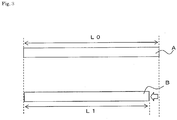
- FIG. 3 is a drawing illustrating a method for defining the shrinkage ratio.
- the cover portion 27 of a length of 20 mm is taken out from the tip of the covered conductive wire 23. This cover portion 27 alone is left at a high temperature of 120 °C for 120 hours.
- the shrinkage ratio at this occasion is defined as (L0 - L1) / L0, wherein the length before heating (A in the drawing) is L0, and the length after heating (B in the drawing) is L1.
- the material or blending quantity of the plasticizer that is to be added to the cover portion 27, for example, should be adjusted.
- plasticizers phthalate, adipic acid, phosphoric acid, and trimellitic acid based materials may be used, for example.
- a material that shrinks by a factor of 7 % or less can be used for the present invention. If the shrinkage ratio exceeds 7 %, the compression force of the cover portion 27 against the inner surface of the cover crimping portion 9 decreases after heating. If a desired compression force cannot be obtained, the adhesive force between the cover portion 27 and the cover crimping portion 9 is insufficient and water entry may occur.
- the quantity of each of the added platicizers is decided as appropriate, evaluating the relationship between added quantity and shrinkage ratio, so that the shrinkage ratio is 7 % or less.
- the minimum of the shrinkage ratio is not limited, taking manufacturability and the like into consideration, it is preferable to use a material having a shrinkage ratio of 2 % or more after being left at a high temperature of 120 °C for 120 hours.
- FIG. 4 is a drawing showing a profile of compression force of resin at a high temperature.
- Curves C, D, and E in FIG. 4 are for the resin to which displacement corresponding to the compression rates at the cover crimping portion of 50 %, 80 %, and 90 % is given, respectively.
- Predetermined displacement is given to each of test pieces of the resin so as to obtain the above compression rates and its repulsive force is measured. The obtained change in repulsive force is shown as the change in compression force.
- the compression rate is preferably 80 % or less. In a case in which the compression rate exceeds 80 %, the compression rate may be 80 % or more if the compression rate of 95 kPa or more can be obtained.
- the compression rate is required to be 90 % or less at minimum.
- the compression rate is 50 % or more to prevent the cover portion 27 from crushing and breaking.
- the compression rate can be expressed as A1 / A0, wherein A0 is a total cross sectional area of the covered conductive wire 23 at the cover portion 27 before crimping and A1 is an inner total cross sectional area of the cover crimping portion 9 after crimping.
- FIG. 5 is an exploded perspective view showing a state before the covered conducive wire 23 is inserted into the terminal 1.
- a predetermined length of the cover portion 27 at the tip of the covered conductive wire 23 is removed to expose the conductive wire 25.
- the covered conductive wire 23 is inserted into the tubular crimping portion 5.
- the exposed part of the conductive wire 25 is positioned inside the conductor crimping portion 7, and the cover portion 27 is positioned inside the cover crimping portion 9.
- the crimping portion 5 is rolled up into a substantially tubular shape and its edge parts are joined together at the joint portion 21.
- the sealed portion 11 is provided at the front-end portion of the crimping portion 5 (on the side of the terminal body 3). That is, the crimping portion 5 is sealed except for the rear-end portion 19 into which the covered conductive wire 23 is inserted.
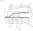
- FIG. 6(a) is a cross-sectional view showing the molds 31a and 31b and the like before crimping
- FIG. 6(b) is a cross-sectional view showing the crimping portion 5 during crimping.
- the mold 31a has a semi-tubular cavity extending in the longitudinal direction, and includes a large-diameter portion 34, which corresponds to the cover crimping portion 9 and has a radius slightly smaller than the radius of the cover crimping portion 9, and a small-diameter portion 32, which corresponds to the conductor crimping portion 7 and has a radius smaller than the larger-diameter portion 34.
- the mold 31b has a semi-tubular cavity extending in the longitudinal direction, and the radii of the parts corresponding to the conductor crimping portion 7 and the cover crimping portion 9 differ in a similar way as in the mold 31a.
- the large-diameter portion 34 is a part that crimps the cover crimping portion 9, and the small-diameter portion 32 is a part that crimps the conductor crimping portion 7.
- the molds 31a and 31b are meshed together to compress the crimping portion 5 so that the crimping portion 5 is crimped to the conductive wire 25 and the cover portion 27. In this way, the terminal-equipped electrical wire 10 is manufactured.
- This terminal-equipped electrical wire 10 according to the present invention is used in motor vehicles and the like for example, and there is a case in which the terminal-equipped electrical wire 10 may be exposed to a high temperature condition such as inside an engine compartment. Thus, for those uses, it is required that water tightness is still maintained at high temperatures.
- the cover portion 27 is formed of hard resin or the thickness of the cover portion 27 is too thin for example, it may be difficult to make the compression rate small enough. For this reason, the compression rate for crimping the cover portion 27 is required to be relatively large. In this case, the compression force may immediately fall below the desired value due to the stress relaxation caused by the shrinking of the cover portion 27.
- the crimping portion 5 can be sealed by adhering the inner surface of the cover crimping portion 9 with the outer surface of the cover portion 27. At this time, parts of the crimping portion 5 other than the rear-end portion 19 are sealed water-tightly by the joint portion 21 and the sealed portion 11, and thus the moisture entry into the crimping portion 5 can be prevented.
- such an influence of the stress relaxation can be reduced by setting the shrinkage ratio of the cover portion 27 in a proper range.
- the compression rate is relatively high as 80 %, it is possible to suppress the decreasing of the compression force under high temperature and to obtain required water tightness.
- the terminal-equipped electrical wire 10 having an excellent water cut-off performance can be manufactured by properly setting the shrinkage ratio of the resin forming the cover portion 27.
- the compression force can be maintained even for the resin having a relatively large compression rate and being held at a high temperature.
- FIG. 7 (a) and FIG. 7 (b) are drawings to show a crimping process according to the second embodiment.
- FIG. 7 (a) is a cross sectional view showing molds 35a and 35b and the like before crimping
- FIG. 7 (b) is a cross sectional view showing the crimping portion 5 during crimping.
- the same notations as in FIG. 6 (a) , FIG. 6 (b) , and the like will be used for the same structure as in the first embodiment and redundant descriptions will be omitted.
- the second embodiment is configured almost as the same as the first embodiment except that protruded linear-portions 39 are formed on the cover crimping portion 9 in a crimping step.
- Each of the molds 35a and 35b has protruding portions 37 formed, which protrude inward.
- the protruding portions 37 are continuous in circumferential direction on inner circumferential surfaces of the molds 35a and 35b. That is, when the molds 35a and 35b are put together, the protruded portions 37 are continuous in ring shapes in the inner circumferential direction of the molds 35a and 35b.
- the parts of outer circumferential surfaces of the cover crimping portion 9 corresponding to the protruding portions 37 of the molds 35a and 35b are pushed in strongly.
- the protruded linear-portions 39 that protrude toward the inner side of the diameter direction are formed at the parts corresponding to the protruded portions 37 of the molds 35a and 35b. That is, recessed grooves corresponding to the linear-portions 39 are formed on the outer circumferential surface of the linear-portions 39 of the cover crimping portion 9.
- the protruded linear-portions 39 are the parts having smaller diameters than the other parts.
- the number of arrangement of the protruded linear-portions 39 is not necessarily two as shown in the drawing, but should be at least one. However, to improve water cut-off performance, it is preferable that two or more rows of protruded linear-portions 39 are formed at intervals.
- the same effects as in the first embodiment can be obtained.
- the protruded linear-portions 39 further enhanced water cut-off performance can be obtained.
- the protruded linear-portions 39 are formed in the crimping step, the linear protruded-portions do not get in the way when the covered conductive wire 23 is inserted.
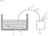
- FIG. 8 shows an outline of the evaluation method. Evaluation was done by placing the terminal 1 crimped to the covered conductive wire 23 into a water tank 41, inserting an end part of the 150 mm long covered conductive wire 23 into a container 45, and applying a negative pressure using a pump 47 so that the pressure inside the container 45 is kept at -30 kPa for ten minutes.
- the compression rate of each of the terminal-equipped electrical wires provided for the test is varied between 40 % and 90 %.
- the cover shrinkage ratios are varied by changing the various factors, such as materials and thickness of the cover portion 27 of the covered conductive wire 23 or heating conditions.
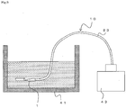
- FIG. 9 shows an outline of the evaluation method. Evaluation was done by placing the terminal 1 crimped with the covered conductive wire 23 into the water tank 41, and supplying pressured air (30 kPa) for one minute from an end portion of the 150 mm long covered conductive wire 23 to the terminal 1 using a regulator 43.
- the terminal-equipped electrical wires provided for this test are the same as in the above-mentioned negative pressure test.
- the results are shown in Table 2.
- Table 2 Compression rate % Cover shrinking factor 2% 5% 7% 9% 11%
- protruded linear-portions 40% average average average average bad 50% good good good average bad 60% good good good average bad 70% good good good good average bad 80% good good good average bad 85% good good good average bad 90% good good average bad bad bad bad
- protruded linear-portions 40% average average average average bad 50% good good bad bad 60% good good good bad bad 70% average average bad bad bad 80% average average bad bad bad bad 85% average average bad bad bad 90% average average bad bad bad bad
- a plurality of the terminal-equipped electrical wires of the present invention may be bundled in use.
- a structure of a plurality of the terminal-equipped electrical wires bundled together is called a wire harness structure.
Landscapes
- Engineering & Computer Science (AREA)
- Manufacturing & Machinery (AREA)
- Mechanical Engineering (AREA)
- Chemical & Material Sciences (AREA)
- Combustion & Propulsion (AREA)
- Transportation (AREA)
- Connections Effected By Soldering, Adhesion, Or Permanent Deformation (AREA)
- Insulated Conductors (AREA)
Abstract
Description
- This invention relates to an electrical wire with a terminal (hereinafter, a terminal-equipped electrical wire) and the like that are used for motor vehicles and the like.
- For connecting an electrical wire and a terminal in a wire harness for motor vehicles, crimp joining, in which an electrical wire is caulked and crimped by a terminal called open-barrel type, has been commonly known. However, in such a wire harness, if moisture or the like adheres to the connecting part of the electrical wire and the terminal, oxidization of the surface of the metal used for the electrical wire progresses, increasing the resistance at the joint part. Also, if different metals are used for the electrical wire and the terminal, corrosion between different metals may progress. The progress of corrosion of metal materials at the connecting part causes cracks or contact failure at the connecting part, and its effect on product life is unavoidable. Particularly in recent years, a wire harness having electrical wires made of aluminum alloy and terminals made of copper alloy has been in practical use, and the problem of corrosion at the joint part has become noteworthy.
- Here, if moisture adheres to the contacting part of different metals such as aluminum and copper for example, so-called electrolytic corrosion may occur due to difference in corrosion potential. Since the potential difference between aluminum and copper is especially large, corrosion on the side of aluminum, which is an electrically base metal, progresses. Thus, the connection state between a conductive wire and a crimp terminal becomes unstable, causing an increase in contact resistance or in electrical resistance due to decrease in wire diameters, and, furthermore, disconnection of the wire, which may result in malfunction or breakdown of the electrical components.
- For such a wire harness having different metals contacting with each other, a method using a terminal having a tubular crimping portion of which one end is closed has been proposed, for example (Patent Document 1): the method includes inserting an end part of an electrical wire into the tubular crimping portion, and then crimping the tubular crimping portion by caulking so as to prevent the end part of the core wires from adhesion of moisture such as rain water or sea water.
- [Patent Document 1] Japanese Unexamined Patent Application Publication No.
2006-331931 JP-A-2006-331931 - However, with a crimping portion having an end part sealed as in
Patent Document 1, water may enter from the crimping portion when adhesion is not sufficient especially after being held at a high temperature. - The present invention was achieved in view of such problems. Its object is to provide a terminal-equipped electrical wire and the like that can have high water cut-off performance.
- To achieve the above object, a first invention provides a terminal-equipped electrical wire including a covered conductive wire connected with a terminal. The terminal includes a crimping portion, which crimps the covered conductive wire, and a terminal body. The crimping portion is in a tubular shape with a sealed end and includes a cover crimping portion, which crimps a cover portion, and a conductor crimping portion, which crimps a conductive wire exposed from the cover portion. The resin forming the cover portion shrinks by a factor of 7 % or less after being left at a high temperature of 120 °C for 120 hours.
- It is preferable that a compression rate of the cover crimping portion is 80 % or less.
- The cover crimping portion may include a protruded linear-portion that protrudes toward an inner surface of the cover crimping portion and is provided as a ring shape in a circumferential direction. On the outer circumference surface of the protruded linear-portion, a recess groove corresponding to the protruded linear-portion may be formed.
- A plurality of the protruded linear-portions may be provided at intervals in a longitudinal direction of the cover crimping portion.
- According to the first invention, after being held at a high temperature, the shrinkage ratio is still below a predetermined value and thus high compression force can be obtained. Thus, adhesion between the cover portion and the terminal is maintained at high temperatures. This can prevent moisture entry from a gap between the crimp terminal and the cover portion into the terminal and adhesion of water to the contacting part of the electrical wire and the terminal.
- In addition, if the compression rate of the cover crimping portion is greater than 80 %, it is difficult to obtain the high compression force at the time of crimping and is difficult to maintain the compression force greater than the predetermined value when being held at high temperatures. Thus, in the present invention, the compression rate is preferably 80 % or less.
- In addition, by providing the ring-shaped protruded linear-portion, which protrudes toward the inner surface of the cover crimping portion, in the circumferential direction of the insulating cover portion, water tightness can be obtained with certainty for all the areas in the circumferential direction.
- Moreover, providing a plurality of the protruded linear-portions in the longitudinal direction can further improve the water tightness.
- A second invention provides a wire harness structure in which a plurality of the terminal-equipped electrical wires according to the first invention are bundled together.
- In the present invention, a plurality of the terminal-equipped electrical wires can be bundled together in use.
- The present invention can provide a terminal-equipped electrical wire and the like that can have high water cut-off performance.
-
-
FIG. 1 is a perspective view of a terminal-equippedelectrical wire 10. -
FIG. 2 is a cross-sectional view of the terminal-equippedelectrical wire 10. -
FIG. 3 is a drawing showing a definition of shrinkage ratio. -
FIG. 4 is a schematic view showing a profile of compression force at a high temperature. -
FIG. 5 is an exploded perspective view of the terminal-equippedelectrical wire 10. -
FIG. 6 (a) is a cross-sectional view showing a crimpingportion 5 disposed between a mold 31a and a mold 31b before crimping. -
FIG. 6 (b) is a cross-sectional view showing the crimpingportion 5 disposed between the mold 31a and the mold 31b after crimping. -
FIG. 7 (a) is a cross-sectional view showing the crimpingportion 5 disposed between a mold 35a and a mold 35b before crimping. -
FIG. 7 (b) is a cross-sectional view showing the crimpingportion 5 disposed between the mold 35a and the mold 35b after crimping. -
FIG. 8 is a schematic view showing a testing device. -
FIG. 9 is a schematic view showing another testing device. -
FIG. 1 is a perspective view showing a terminal-equippedelectrical wire 10 according to an embodiment of the present invention, andFIG. 2 is a cross-sectional view in an axial direction of the terminal-equippedelectrical wire 10. The terminal-equippedelectrical wire 10 includes aterminal 1 and a coveredconductive wire 23 that are crimped together. - The covered
conductive wire 23 includes aconductive wire 25 covered by aninsulating cover portion 27. Theconductive wire 25 is made of, for example, aluminum based material. When inserting the coveredconductive wire 23 into a crimpingportion 5 of theterminal 1, a part of thecover portion 27 at the tip of the coveredconductive wire 23 is removed to expose theconductive wire 25. For thecover portion 27, any of commonly used materials in this technical field, such as polyvinyl chloride (PVC) or polyethylene, can be chosen. - The
terminal 1 is made of copper and includes aterminal body 3 and the crimpingportion 5 to which the coveredconductive wire 23 is crimped. Theterminal body 3 is made of a plate-like member of a predetermined shape that is formed into a tubular body having a rectangular cross section. Theterminal body 3 has an elastic contacting piece 15, which is formed by folding the plate-like member into the rectangular tubular body, at a front-end portion 17. Theterminal body 3 is connected to a male terminal or the like that is to be inserted from the front-end portion 17. - The crimping
portion 5 is formed by rolling up a plate-like material into a cylinder having a circular cross section, and the side edges of the plate-like material are butted to each other and joined at ajoint portion 21 to be integrated. The coveredconductive wire 23 is inserted into the tubularly formed crimpingportion 5 from a rear-end portion 19. In addition, a sealedportion 11 is provided at the front end of the crimping portion 5 (on the side of the terminal body 3). That is, the crimpingportion 5 is in a substantially tubular shape with a sealed end, and parts of the crimpingportion 5 except for the rear-end portion 19 into which the covered conductive wire is to be inserted are sealed. Thejoint portion 21 and the sealedportion 11 are welded by, for example, laser welding or the like. - The crimping
portion 5 includes acover crimping portion 9, which crimps thecover portion 27 of the coveredconductive wire 23, and aconductor crimping portion 7, which crimps theconductive wire 25 that is exposed by removing thecover portion 27 at a tip part of the coveredconductive wire 23. - As mentioned above, polyvinyl chloride or non halogen material, for example, can be used for the
cover portion 27 of the coveredconductive wire 23, which may be mixed with plasticizer, filler, and/or stabilizer as required. - A material that shrinks by a factor of 7 % or less after being left at a high temperature of 120 °C for 120 hours is used for resin forming the
cover portion 27 of the present invention.FIG. 3 is a drawing illustrating a method for defining the shrinkage ratio. Thecover portion 27 of a length of 20 mm is taken out from the tip of the coveredconductive wire 23. Thiscover portion 27 alone is left at a high temperature of 120 °C for 120 hours. The shrinkage ratio at this occasion is defined as (L0 - L1) / L0, wherein the length before heating (A in the drawing) is L0, and the length after heating (B in the drawing) is L1. - To adjust the shrinkage ratio of the
cover portion 27, the material or blending quantity of the plasticizer that is to be added to thecover portion 27, for example, should be adjusted. As plasticizers, phthalate, adipic acid, phosphoric acid, and trimellitic acid based materials may be used, for example. - A material that shrinks by a factor of 7 % or less can be used for the present invention. If the shrinkage ratio exceeds 7 %, the compression force of the
cover portion 27 against the inner surface of thecover crimping portion 9 decreases after heating. If a desired compression force cannot be obtained, the adhesive force between thecover portion 27 and thecover crimping portion 9 is insufficient and water entry may occur. The quantity of each of the added platicizers is decided as appropriate, evaluating the relationship between added quantity and shrinkage ratio, so that the shrinkage ratio is 7 % or less. - Although the minimum of the shrinkage ratio is not limited, taking manufacturability and the like into consideration, it is preferable to use a material having a shrinkage ratio of 2 % or more after being left at a high temperature of 120 °C for 120 hours.
-
FIG. 4 is a drawing showing a profile of compression force of resin at a high temperature. Curves C, D, and E inFIG. 4 are for the resin to which displacement corresponding to the compression rates at the cover crimping portion of 50 %, 80 %, and 90 % is given, respectively. Predetermined displacement is given to each of test pieces of the resin so as to obtain the above compression rates and its repulsive force is measured. The obtained change in repulsive force is shown as the change in compression force. - As shown in
FIG. 4 , in a case of curve C in which the compression rate is small (amount of compression is large), sufficient compression force can be maintained after being held at a high temperature. On the contrary, in cases of curves D and E in which the compression rates are large (amount of compression is small), compression force is low and, particularly for the curve E, compression force is 95 kPa or less. This is below the passing mark of a leaking test, which will be described later, and may lead to water entry. Consequently, the compression rate is preferably 80 % or less. In a case in which the compression rate exceeds 80 %, the compression rate may be 80 % or more if the compression rate of 95 kPa or more can be obtained. However, to obtain high adhesive force between thecover portion 27 and thecover crimping portion 9, the compression rate is required to be 90 % or less at minimum. - In addition, although there is no limit for the minimum value of the compression rate, it is preferable that the compression rate is 50 % or more to prevent the
cover portion 27 from crushing and breaking. - Here, the compression rate can be expressed as A1 / A0, wherein A0 is a total cross sectional area of the covered
conductive wire 23 at thecover portion 27 before crimping and A1 is an inner total cross sectional area of thecover crimping portion 9 after crimping. - Next, a process of forming a terminal-equipped electrical wire will be described.
FIG. 5 is an exploded perspective view showing a state before the coveredconducive wire 23 is inserted into theterminal 1. First, as shown inFIG. 5 , a predetermined length of thecover portion 27 at the tip of the coveredconductive wire 23 is removed to expose theconductive wire 25. Next, the coveredconductive wire 23 is inserted into thetubular crimping portion 5. At this time, the exposed part of theconductive wire 25 is positioned inside theconductor crimping portion 7, and thecover portion 27 is positioned inside thecover crimping portion 9. - As mentioned above, the crimping
portion 5 is rolled up into a substantially tubular shape and its edge parts are joined together at thejoint portion 21. In addition, the sealedportion 11 is provided at the front-end portion of the crimping portion 5 (on the side of the terminal body 3). That is, the crimpingportion 5 is sealed except for the rear-end portion 19 into which the coveredconductive wire 23 is inserted. -
FIG. 6(a) is a cross-sectional view showing the molds 31a and 31b and the like before crimping, andFIG. 6(b) is a cross-sectional view showing the crimpingportion 5 during crimping. The mold 31a has a semi-tubular cavity extending in the longitudinal direction, and includes a large-diameter portion 34, which corresponds to thecover crimping portion 9 and has a radius slightly smaller than the radius of thecover crimping portion 9, and a small-diameter portion 32, which corresponds to theconductor crimping portion 7 and has a radius smaller than the larger-diameter portion 34. The mold 31b has a semi-tubular cavity extending in the longitudinal direction, and the radii of the parts corresponding to theconductor crimping portion 7 and thecover crimping portion 9 differ in a similar way as in the mold 31a. The large-diameter portion 34 is a part that crimps thecover crimping portion 9, and the small-diameter portion 32 is a part that crimps theconductor crimping portion 7. - As shown in
FIG. 6 (b) , the molds 31a and 31b are meshed together to compress the crimpingportion 5 so that the crimpingportion 5 is crimped to theconductive wire 25 and thecover portion 27. In this way, the terminal-equippedelectrical wire 10 is manufactured. - This terminal-equipped
electrical wire 10 according to the present invention is used in motor vehicles and the like for example, and there is a case in which the terminal-equippedelectrical wire 10 may be exposed to a high temperature condition such as inside an engine compartment. Thus, for those uses, it is required that water tightness is still maintained at high temperatures. - To withstand such high temperatures, water tightness must be maintained when, for example, being left at a high temperature of 120 C° for 120 hours. However, if the shrinkage ratio of the resin forming the
cover portion 27 is large as mentioned above, it is difficult to maintain sufficient compression force after being left at a high temperature. That is, the stress generated on the coveringportion 27 is relaxed, lowering the adhesive force between thecover portion 27 and thecover crimping portion 9, so that it may not be possible to obtain the desired water tightness. - Meanwhile, as mentioned above, it is possible to maintain the required compression force by making the compression rate at the time of crimping small, even if stress relaxation occurs at a high temperature. However, if the
cover portion 27 is formed of hard resin or the thickness of thecover portion 27 is too thin for example, it may be difficult to make the compression rate small enough. For this reason, the compression rate for crimping thecover portion 27 is required to be relatively large. In this case, the compression force may immediately fall below the desired value due to the stress relaxation caused by the shrinking of thecover portion 27. - However, with the large compression rate, water tightness can still be obtained if the
cover portion 27 and thecover crimping portion 9 are adhered with certainty. That is, the crimpingportion 5 can be sealed by adhering the inner surface of thecover crimping portion 9 with the outer surface of thecover portion 27. At this time, parts of the crimpingportion 5 other than the rear-end portion 19 are sealed water-tightly by thejoint portion 21 and the sealedportion 11, and thus the moisture entry into the crimpingportion 5 can be prevented. - In the present invention, such an influence of the stress relaxation can be reduced by setting the shrinkage ratio of the
cover portion 27 in a proper range. For example, when the compression rate is relatively high as 80 %, it is possible to suppress the decreasing of the compression force under high temperature and to obtain required water tightness. - As in the present embodiment described above, the terminal-equipped
electrical wire 10 having an excellent water cut-off performance can be manufactured by properly setting the shrinkage ratio of the resin forming thecover portion 27. For example, the compression force can be maintained even for the resin having a relatively large compression rate and being held at a high temperature. - Next, a second embodiment will be described.
FIG. 7 (a) andFIG. 7 (b) are drawings to show a crimping process according to the second embodiment.FIG. 7 (a) is a cross sectional view showing molds 35a and 35b and the like before crimping andFIG. 7 (b) is a cross sectional view showing the crimpingportion 5 during crimping. In the descriptions below, the same notations as inFIG. 6 (a) ,FIG. 6 (b) , and the like will be used for the same structure as in the first embodiment and redundant descriptions will be omitted. - The second embodiment is configured almost as the same as the first embodiment except that protruded linear-portions 39 are formed on the
cover crimping portion 9 in a crimping step. - Each of the molds 35a and 35b has protruding
portions 37 formed, which protrude inward. The protrudingportions 37 are continuous in circumferential direction on inner circumferential surfaces of the molds 35a and 35b. That is, when the molds 35a and 35b are put together, the protrudedportions 37 are continuous in ring shapes in the inner circumferential direction of the molds 35a and 35b. The parts of outer circumferential surfaces of thecover crimping portion 9 corresponding to the protrudingportions 37 of the molds 35a and 35b are pushed in strongly. Thus, on the inner circumferential surface of thecover crimping portion 9, the protruded linear-portions 39 that protrude toward the inner side of the diameter direction are formed at the parts corresponding to the protrudedportions 37 of the molds 35a and 35b. That is, recessed grooves corresponding to the linear-portions 39 are formed on the outer circumferential surface of the linear-portions 39 of thecover crimping portion 9. - The protruded linear-portions 39 are the parts having smaller diameters than the other parts. The number of arrangement of the protruded linear-portions 39 is not necessarily two as shown in the drawing, but should be at least one. However, to improve water cut-off performance, it is preferable that two or more rows of protruded linear-portions 39 are formed at intervals.
- By providing the ring shaped protruded linear-portions 39 on the
cover crimping portion 9 in its circumferential direction as above, some parts of thecover portion 27 are crimped by the protruded linear-portions 39 with stronger force than the other parts, forming highly crimped parts. As a result, a further enhanced water cut-off performance can be obtained. - According to the second embodiment, the same effects as in the first embodiment can be obtained. In addition, with the protruded linear-portions 39, further enhanced water cut-off performance can be obtained. In addition, since the protruded linear-portions 39 are formed in the crimping step, the linear protruded-portions do not get in the way when the covered
conductive wire 23 is inserted. - First, to evaluate water leakage, a negative pressure is given to a covered conductive wire side of a terminal-equipped electrical wire that has gone through heating test.
FIG. 8 shows an outline of the evaluation method. Evaluation was done by placing theterminal 1 crimped to the coveredconductive wire 23 into a water tank 41, inserting an end part of the 150 mm long coveredconductive wire 23 into a container 45, and applying a negative pressure using apump 47 so that the pressure inside the container 45 is kept at -30 kPa for ten minutes. - The compression rate of each of the terminal-equipped electrical wires provided for the test is varied between 40 % and 90 %. In addition, the cover shrinkage ratios are varied by changing the various factors, such as materials and thickness of the
cover portion 27 of the coveredconductive wire 23 or heating conditions. The shrinkage ratio of thecover portion 27 according to each of the heating conditions is calculated in advance from the method illustrated inFIG. 3 . To obtain various shrinkage ratios, some samples were left for 120 hours at a high temperature of, not 120 C°, but higher. In other words, samples with larger shrinkage ratios were also used. The samples were tested for ten times (n = 10) under each conditions. The results are shown in Table 1.Table 1 Compression rate % Cover shrinking factor 2% 5% 7% 9% 11% With protruded linear- portions 40% average average average average average 50% excellent excellent excellent excellent excellent 60% excellent excellent excellent excellent excellent 70% excellent excellent excellent excellent excellent 80% excellent excellent excellent excellent excellent 85% excellent excellent excellent good good 90% good good good average average Without protruded linear- portions 40% average average average average average 50% excellent excellent excellent average average 60% excellent excellent excellent average average 70% excellent excellent excellent average average 80% excellent excellent excellent average average 85% excellent excellent excellent average average 90% good good good average bad - In Table 1, "excellent" means 100 % pass, "good" means 80 % to 90 % pass, "average" means 50 % to 70 % pass, and "bad" means pass under 50 %. As for the protruded linear-portions, the terminals with or without the protruded linear-portions 39 illustrated in
FIG. 7 (b) were evaluated. - Some of the samples with compression rate of 40 % had a break in the cover. The evaluations for the samples with compression rates in a range of 50 % to 85 % and cover shrinkage ratios in a range of 2 % to 7 % were all "excellent", regardless of the existence of the protruded linear-portions. On the contrary, the samples without the protruded linear-portions and with cover shrinkage ratios over 7 % had a pass rate of 70 % or less.
- Next, as a severer test, a terminal-equipped electrical wire that has gone through heating test was tested for air leakage. First, air is supplied from the cover portion of the covered conductive wire toward the terminal to evaluate whether air leaks from the rear end portion or not.
FIG. 9 shows an outline of the evaluation method. Evaluation was done by placing theterminal 1 crimped with the coveredconductive wire 23 into the water tank 41, and supplying pressured air (30 kPa) for one minute from an end portion of the 150 mm long coveredconductive wire 23 to theterminal 1 using a regulator 43. - The terminal-equipped electrical wires provided for this test are the same as in the above-mentioned negative pressure test. The results are shown in Table 2.
Table 2 Compression rate % Cover shrinking factor 2% 5% 7% 9% 11% With protruded linear- portions 40% average average average average bad 50% good good good average bad 60% good good good average bad 70% good good good average bad 80% good good good average bad 85% good good good average bad 90% good good average bad bad Without protruded linear- portions 40% average average average average bad 50% good good good bad bad 60% good good good bad bad 70% average average bad bad bad 80% average average bad bad bad 85% average average bad bad bad 90% average average bad bad bad - Some of the samples with compression rate of 40 % had a break in the cover. For the samples with the protruded linear portions and having compression rates in a range of 50 %t to 85 % and cover shrinkage ratios between 2 % and 7%, the evaluations were all "good". For the samples without the protruded linear portions having compression rates in a range of 50 % to 60 % and cover shrinkage ratios between 2 % and 7%, the evaluations were also all "good". On the contrary, the samples with cover shrinkage ratios over 7 % had a pass rate of 70 % or less.
- Although the embodiments of the present invention have been described referring to the attached drawings, the technical scope of the present invention is not limited to the embodiments described above. It is obvious that persons skilled in the art can think out various examples of changes or modifications within the scope of the technical idea disclosed in the claims, and it will be understood that they naturally belong to the technical scope of the present invention.
- For example, although aluminum is used for the electrical wires in the working examples, it is not limited thereto and copper may be used for the electrical wires.
- In addition, a plurality of the terminal-equipped electrical wires of the present invention may be bundled in use. In the present invention, such a structure of a plurality of the terminal-equipped electrical wires bundled together is called a wire harness structure.
-
- 1
- terminal
- 3
- terminal body
- 5
- crimping portion
- 7
- cover crimping portion
- 9
- conductor crimping portion
- 10
- electrical wire with terminal
- 11
- sealed portion
- 15
- elastic contacting piece
- 17
- front-end portion
- 19
- rear-end portion
- 21
- joint portion
- 23
- covered conductive wire
- 25
- conductive wire
- 27
- cover portion
- 31a, 31b, 35a, 35b
- mold
- 32
- small-diameter portion
- 34
- large-diameter portion
- 37
- protruding portion
- 39
- protruded linear-portion
- 41
- water tank
- 43
- regulator
- 45
- container
- 43
- vacuum pump
Claims (5)
- A terminal-equipped electrical wire including a covered conductive wire connected with a terminal, wherein:the terminal includes a crimping portion, which crimps the covered conductive wire, and a terminal body;the crimping portion is in a tubular shape having a closed end, the crimping portion including a cover crimping portion, which crimps a cover portion of the covered conductive wire, and a conductor crimping portion, which crimps a conductive wire exposed from the cover portion; andthe resin forming the cover portion shrinks by a factor of 7 % or less after being left at a high temperature of 120 °C for 120 hours.
- The terminal-equipped electrical wire according to claim 1, wherein:the a compression rate of the cover crimping portion is 80 % or less.
- The terminal-equipped electrical wire according to claim 1, wherein:the cover crimping portion includes a protruded linear-portion that protrudes toward an inner surface of the cover crimping portion and is provided as a ring shape in a circumferential direction; anda recess groove corresponding to the protruded linear-portion is formed on an outer circumference surface of the protruded linear-portion.
- The terminal-equipped electrical wire according to claim 3, wherein:a plurality of the protruded linear-portions are provided at intervals in a longitudinal direction of the cover crimping portion.
- A wire harness structure, wherein:a plurality of the terminal-equipped electrical wires according to one of claims 1 to 4 are bundled together.
Applications Claiming Priority (2)
| Application Number | Priority Date | Filing Date | Title |
|---|---|---|---|
| JP2014170564 | 2014-08-25 | ||
| PCT/JP2015/073792 WO2016031798A1 (en) | 2014-08-25 | 2015-08-25 | Electrical wire with terminal, and wire harness structure |
Publications (2)
| Publication Number | Publication Date |
|---|---|
| EP3188316A1 true EP3188316A1 (en) | 2017-07-05 |
| EP3188316A4 EP3188316A4 (en) | 2018-03-21 |
Family
ID=55399685
Family Applications (1)
| Application Number | Title | Priority Date | Filing Date |
|---|---|---|---|
| EP15836917.3A Withdrawn EP3188316A4 (en) | 2014-08-25 | 2015-08-25 | Electrical wire with terminal, and wire harness structure |
Country Status (6)
| Country | Link |
|---|---|
| US (1) | US9837728B2 (en) |
| EP (1) | EP3188316A4 (en) |
| JP (1) | JPWO2016031798A1 (en) |
| KR (1) | KR20170019435A (en) |
| CN (1) | CN106663881A (en) |
| WO (1) | WO2016031798A1 (en) |
Families Citing this family (6)
| Publication number | Priority date | Publication date | Assignee | Title |
|---|---|---|---|---|
| JP2018092739A (en) * | 2016-11-30 | 2018-06-14 | 古河電気工業株式会社 | Electric wire with terminal, terminal, manufacturing method of electric wire with terminal, and wiring harness |
| CN107123867B (en) * | 2017-06-05 | 2019-05-10 | 吉林省中赢高科技有限公司 | A kind of joint of copper terminal and aluminum wire and magnetic induction welding method thereof |
| EP3711663B1 (en) * | 2017-11-15 | 2023-07-26 | Nippon Telegraph And Telephone Corporation | Composite wiring, signal acquisition member, and production method of same |
| BR202019016911Y1 (en) * | 2019-08-14 | 2024-03-12 | Gridspertise Latam S.A | ELECTRICAL CONNECTION BLOCK |
| WO2022009879A1 (en) * | 2020-07-07 | 2022-01-13 | 古河電気工業株式会社 | Terminal-attached electric wire, wire harness, and method for manufacturing terminal-attached electric wire |
| DE102021127516A1 (en) * | 2020-11-19 | 2022-05-19 | Yazaki Corporation | Electrical cable with connection and connection crimping device |
Family Cites Families (15)
| Publication number | Priority date | Publication date | Assignee | Title |
|---|---|---|---|---|
| JP2000144099A (en) * | 1998-11-05 | 2000-05-26 | Sumitomo Wiring Syst Ltd | Water shut off member |
| JP2002216862A (en) | 2001-01-19 | 2002-08-02 | Yazaki Corp | Waterproof structure and waterproofing method of terminal and wire connection |
| JP4616700B2 (en) | 2005-05-27 | 2011-01-19 | 三菱電線工業株式会社 | Wire connection structure |
| JP5320809B2 (en) * | 2008-05-08 | 2013-10-23 | 住友電装株式会社 | Water stop structure of wire harness and method of forming water stop |
| JP5306972B2 (en) * | 2009-11-26 | 2013-10-02 | 古河電気工業株式会社 | Wire harness, method for manufacturing wire harness |
| EP2650972B1 (en) * | 2010-12-08 | 2016-03-16 | Furukawa Electric Co., Ltd. | Crimp terminal, connection structure, and production method for same |
| JP5710996B2 (en) * | 2011-02-04 | 2015-04-30 | 矢崎総業株式会社 | Electric wire and terminal connection structure and manufacturing method thereof |
| JP2013025932A (en) * | 2011-07-19 | 2013-02-04 | Auto Network Gijutsu Kenkyusho:Kk | Anti-corrosion agent, covered wire with terminal, and wiring harness |
| JP5767551B2 (en) * | 2011-10-05 | 2015-08-19 | 古河電気工業株式会社 | Crimp terminal, connection structure and connector |
| JP5535408B1 (en) | 2012-07-09 | 2014-07-02 | 古河電気工業株式会社 | Crimp terminal, connection structure and connector |
| WO2014014103A1 (en) * | 2012-07-20 | 2014-01-23 | 古河電気工業株式会社 | Connected structure, connector, and manufacturing method for connected structure |
| EP2876731B1 (en) * | 2012-07-20 | 2018-05-02 | Furukawa Electric Co., Ltd. | Crimp terminal |
| WO2014129222A1 (en) | 2013-02-22 | 2014-08-28 | 古河電気工業株式会社 | Terminal, wiring connection structure, and method for manufacturing terminal |
| KR101487368B1 (en) * | 2013-02-22 | 2015-01-29 | 후루카와 덴키 고교 가부시키가이샤 | Crimp terminal, crimp-connection structural body, and method for manufacturing crimp-connection structural body |
| JP6339365B2 (en) * | 2013-12-27 | 2018-06-06 | 古河電気工業株式会社 | Wire harness, method for connecting covered conductor, and wire harness structure |
-
2015
- 2015-08-25 EP EP15836917.3A patent/EP3188316A4/en not_active Withdrawn
- 2015-08-25 KR KR1020177001280A patent/KR20170019435A/en not_active Ceased
- 2015-08-25 CN CN201580038596.7A patent/CN106663881A/en active Pending
- 2015-08-25 US US15/506,522 patent/US9837728B2/en active Active
- 2015-08-25 JP JP2016545535A patent/JPWO2016031798A1/en active Pending
- 2015-08-25 WO PCT/JP2015/073792 patent/WO2016031798A1/en not_active Ceased
Also Published As
| Publication number | Publication date |
|---|---|
| JPWO2016031798A1 (en) | 2017-04-27 |
| WO2016031798A1 (en) | 2016-03-03 |
| CN106663881A (en) | 2017-05-10 |
| US20170274844A1 (en) | 2017-09-28 |
| KR20170019435A (en) | 2017-02-21 |
| EP3188316A4 (en) | 2018-03-21 |
| US9837728B2 (en) | 2017-12-05 |
Similar Documents
| Publication | Publication Date | Title |
|---|---|---|
| US9837728B2 (en) | Electrical wire with terminal, and wire harness structure | |
| EP3125369B1 (en) | Wire harness, connection method between covered conducting wire and terminal, and wire harness structure body | |
| CN104364980B (en) | Method for manufacturing electrical wiring connection structure body, and electrical wiring connection structure body | |
| JP5654178B1 (en) | Wire harness, connection method of terminal and coated conductor, wire harness structure | |
| JP6294859B2 (en) | Terminal, electric wire with terminal, wire harness, connection method between coated conductor and terminal, and crimping management method thereof | |
| US10418772B2 (en) | Method for manufacturing terminal-equipped electrical wires | |
| EP3389154A1 (en) | Spark plug | |
| EP3182533B1 (en) | Spark plug | |
| US9793617B2 (en) | Electrical wire-connecting structure and method for manufacturing electrical wire-connecting structure | |
| JP2017050151A (en) | Terminal, electric wire with terminal, wire harness, connection method between coated conductor and terminal, and crimping management method thereof | |
| EP2770593A2 (en) | Ignition plug | |
| JP6549920B2 (en) | Wire with Terminal, Wire Harness Structure, and Method of Manufacturing Wire with Terminal | |
| JP6490363B2 (en) | Electric wire with terminal, usage of electric wire with terminal, wire harness structure | |
| EP2624383A1 (en) | Spark plug | |
| CN110707443B (en) | wire with terminals | |
| US9853367B2 (en) | Wire harness, method of connecting terminal and coated wire, and mold | |
| CN113748577A (en) | Spark plug electrode and method of manufacturing the same | |
| JP7236513B1 (en) | Spark plug | |
| JP2010205697A (en) | Crimp terminal for high strength small diameter wire | |
| JP6935310B2 (en) | Manufacturing method of electric wire with terminal |
Legal Events
| Date | Code | Title | Description |
|---|---|---|---|
| PUAI | Public reference made under article 153(3) epc to a published international application that has entered the european phase |
Free format text: ORIGINAL CODE: 0009012 |
|
| 17P | Request for examination filed |
Effective date: 20170125 |
|
| AK | Designated contracting states |
Kind code of ref document: A1 Designated state(s): AL AT BE BG CH CY CZ DE DK EE ES FI FR GB GR HR HU IE IS IT LI LT LU LV MC MK MT NL NO PL PT RO RS SE SI SK SM TR |
|
| AX | Request for extension of the european patent |
Extension state: BA ME |
|
| DAV | Request for validation of the european patent (deleted) | ||
| DAX | Request for extension of the european patent (deleted) | ||
| STAA | Information on the status of an ep patent application or granted ep patent |
Free format text: STATUS: THE APPLICATION HAS BEEN WITHDRAWN |
|
| 18W | Application withdrawn |
Effective date: 20180209 |
|
| A4 | Supplementary search report drawn up and despatched |
Effective date: 20180216 |
|
| RIC1 | Information provided on ipc code assigned before grant |
Ipc: H01R 43/00 20060101ALI20180212BHEP Ipc: H01R 4/18 20060101AFI20180212BHEP Ipc: H01R 4/62 20060101ALI20180212BHEP Ipc: H01R 43/048 20060101ALI20180212BHEP |
|
| D17P | Request for examination filed (deleted) |