EP3188194A2 - Collimator and inspection system having the same - Google Patents
Collimator and inspection system having the same Download PDFInfo
- Publication number
- EP3188194A2 EP3188194A2 EP16191080.7A EP16191080A EP3188194A2 EP 3188194 A2 EP3188194 A2 EP 3188194A2 EP 16191080 A EP16191080 A EP 16191080A EP 3188194 A2 EP3188194 A2 EP 3188194A2
- Authority
- EP
- European Patent Office
- Prior art keywords
- collimator
- collimating slit
- shielding part
- ray
- shielding
- Prior art date
- Legal status (The legal status is an assumption and is not a legal conclusion. Google has not performed a legal analysis and makes no representation as to the accuracy of the status listed.)
- Granted
Links
Images





Classifications
-
- G—PHYSICS
- G21—NUCLEAR PHYSICS; NUCLEAR ENGINEERING
- G21K—HANDLING OF PARTICLES OR IONISING RADIATION NOT OTHERWISE PROVIDED FOR; IRRADIATION DEVICES; GAMMA RAY OR X-RAY MICROSCOPES
- G21K1/00—Arrangements for handling particles or ionising radiation, e.g. focusing or moderating
- G21K1/02—Arrangements for handling particles or ionising radiation, e.g. focusing or moderating using diaphragms, collimators
- G21K1/04—Arrangements for handling particles or ionising radiation, e.g. focusing or moderating using diaphragms, collimators using variable diaphragms, shutters, choppers
-
- G—PHYSICS
- G21—NUCLEAR PHYSICS; NUCLEAR ENGINEERING
- G21K—HANDLING OF PARTICLES OR IONISING RADIATION NOT OTHERWISE PROVIDED FOR; IRRADIATION DEVICES; GAMMA RAY OR X-RAY MICROSCOPES
- G21K1/00—Arrangements for handling particles or ionising radiation, e.g. focusing or moderating
- G21K1/02—Arrangements for handling particles or ionising radiation, e.g. focusing or moderating using diaphragms, collimators
- G21K1/04—Arrangements for handling particles or ionising radiation, e.g. focusing or moderating using diaphragms, collimators using variable diaphragms, shutters, choppers
- G21K1/043—Arrangements for handling particles or ionising radiation, e.g. focusing or moderating using diaphragms, collimators using variable diaphragms, shutters, choppers changing time structure of beams by mechanical means, e.g. choppers, spinning filter wheels
-
- G—PHYSICS
- G01—MEASURING; TESTING
- G01N—INVESTIGATING OR ANALYSING MATERIALS BY DETERMINING THEIR CHEMICAL OR PHYSICAL PROPERTIES
- G01N23/00—Investigating or analysing materials by the use of wave or particle radiation, e.g. X-rays or neutrons, not covered by groups G01N3/00 – G01N17/00, G01N21/00 or G01N22/00
- G01N23/02—Investigating or analysing materials by the use of wave or particle radiation, e.g. X-rays or neutrons, not covered by groups G01N3/00 – G01N17/00, G01N21/00 or G01N22/00 by transmitting the radiation through the material
- G01N23/04—Investigating or analysing materials by the use of wave or particle radiation, e.g. X-rays or neutrons, not covered by groups G01N3/00 – G01N17/00, G01N21/00 or G01N22/00 by transmitting the radiation through the material and forming images of the material
-
- G—PHYSICS
- G01—MEASURING; TESTING
- G01V—GEOPHYSICS; GRAVITATIONAL MEASUREMENTS; DETECTING MASSES OR OBJECTS; TAGS
- G01V5/00—Prospecting or detecting by the use of ionising radiation, e.g. of natural or induced radioactivity
- G01V5/20—Detecting prohibited goods, e.g. weapons, explosives, hazardous substances, contraband or smuggled objects
- G01V5/22—Active interrogation, i.e. by irradiating objects or goods using external radiation sources, e.g. using gamma rays or cosmic rays
-
- G—PHYSICS
- G01—MEASURING; TESTING
- G01N—INVESTIGATING OR ANALYSING MATERIALS BY DETERMINING THEIR CHEMICAL OR PHYSICAL PROPERTIES
- G01N2223/00—Investigating materials by wave or particle radiation
- G01N2223/03—Investigating materials by wave or particle radiation by transmission
-
- G—PHYSICS
- G01—MEASURING; TESTING
- G01N—INVESTIGATING OR ANALYSING MATERIALS BY DETERMINING THEIR CHEMICAL OR PHYSICAL PROPERTIES
- G01N2223/00—Investigating materials by wave or particle radiation
- G01N2223/10—Different kinds of radiation or particles
- G01N2223/101—Different kinds of radiation or particles electromagnetic radiation
- G01N2223/1013—Different kinds of radiation or particles electromagnetic radiation gamma
-
- G—PHYSICS
- G01—MEASURING; TESTING
- G01N—INVESTIGATING OR ANALYSING MATERIALS BY DETERMINING THEIR CHEMICAL OR PHYSICAL PROPERTIES
- G01N2223/00—Investigating materials by wave or particle radiation
- G01N2223/10—Different kinds of radiation or particles
- G01N2223/101—Different kinds of radiation or particles electromagnetic radiation
- G01N2223/1016—X-ray
-
- G—PHYSICS
- G01—MEASURING; TESTING
- G01N—INVESTIGATING OR ANALYSING MATERIALS BY DETERMINING THEIR CHEMICAL OR PHYSICAL PROPERTIES
- G01N2223/00—Investigating materials by wave or particle radiation
- G01N2223/10—Different kinds of radiation or particles
- G01N2223/106—Different kinds of radiation or particles neutrons
-
- G—PHYSICS
- G01—MEASURING; TESTING
- G01N—INVESTIGATING OR ANALYSING MATERIALS BY DETERMINING THEIR CHEMICAL OR PHYSICAL PROPERTIES
- G01N2223/00—Investigating materials by wave or particle radiation
- G01N2223/30—Accessories, mechanical or electrical features
- G01N2223/316—Accessories, mechanical or electrical features collimators
-
- G—PHYSICS
- G01—MEASURING; TESTING
- G01N—INVESTIGATING OR ANALYSING MATERIALS BY DETERMINING THEIR CHEMICAL OR PHYSICAL PROPERTIES
- G01N2223/00—Investigating materials by wave or particle radiation
- G01N2223/30—Accessories, mechanical or electrical features
- G01N2223/33—Accessories, mechanical or electrical features scanning, i.e. relative motion for measurement of successive object-parts
- G01N2223/3301—Accessories, mechanical or electrical features scanning, i.e. relative motion for measurement of successive object-parts beam is modified for scan, e.g. moving collimator
-
- G—PHYSICS
- G01—MEASURING; TESTING
- G01N—INVESTIGATING OR ANALYSING MATERIALS BY DETERMINING THEIR CHEMICAL OR PHYSICAL PROPERTIES
- G01N2223/00—Investigating materials by wave or particle radiation
- G01N2223/30—Accessories, mechanical or electrical features
- G01N2223/33—Accessories, mechanical or electrical features scanning, i.e. relative motion for measurement of successive object-parts
- G01N2223/3302—Accessories, mechanical or electrical features scanning, i.e. relative motion for measurement of successive object-parts object and detector fixed
-
- G—PHYSICS
- G01—MEASURING; TESTING
- G01N—INVESTIGATING OR ANALYSING MATERIALS BY DETERMINING THEIR CHEMICAL OR PHYSICAL PROPERTIES
- G01N2223/00—Investigating materials by wave or particle radiation
- G01N2223/60—Specific applications or type of materials
- G01N2223/66—Specific applications or type of materials multiple steps inspection, e.g. coarse/fine
Definitions
- Embodiments of the present disclosure relate to an adjustable collimator and an inspection system, in particular, to an inspection system and an inspection method for scanning a vehicle.
- An inspection system typically uses a ray such as X-ray or the like to inspect an object to be inspected. During such an inspection system is used, it is generally required to ensure an image quality while controlling or supervising exterior radiation, i.e. boundary dose rate.
- the image quality is improved by increasing the dose rate in a case that a radiation protection device and an area of a radiation controlled area are kept unchanged, in such case, the boundary dose rate is inevitably increased.
- the image quality has to be sacrificed in order to control the boundary dose rate.
- the existing inspection system is not capable of addressing this contradiction well.
- the present disclosure provides an adjustable collimator and an inspection system having the same. Further, the present disclosure provides an inspection system for scanning a vehicle and an inspection method using the inspection system.
- a collimator can be adjusted as required to vary an inclined angle and an elevation angle of a ray beam, thereby allowing to increase a dose rate of the ray to improve a partial image quality.
- ray doses in a region where wheels are located and in empty compartments or air compartments in and above a top of a vehicle container may be restricted to reduce a transmitted dose of the entire system and thus reduce a scattered dose indirectly, thereby achieving an objective of reducing a boundary dose rate; alternatively, to improve an image quality of a suspected area while the radiation supervised area is not enlarged and an original safety standard is kept.
- a collimator comprising:
- the shielding member is movable relative to the collimator body to completely shield the ray beam propagating through the collimating slit.
- the shielding member is configured to shield at least a part of the collimating slit as it moves relative to the collimator body, so as to allow the ray propagating through a remaining part of the collimating slit to form a continuous ray beam, the beam divergent angle of the continuous ray beam or both the beam divergent angle and the elevation angle of the continuous ray beam being varied as the shielding member moves relative to the collimator body.
- the shielding member is capable of adjusting steplessly the beam divergent angle of the ray beam propagating through the collimating slit or both the beam divergent angle and the elevation angle of the ray beam propagating through the collimating slit as the shielding member moves relative to the collimator body.
- the shielding member comprises a first shielding part which is disposed adjacent to the first end of the collimating slit and is movable in the longitudinal direction of the collimating slit relative to the collimator body; and/or a second shielding part which is disposed adjacent to the second end of the collimating slit and is movable in the longitudinal direction of the collimating slit relative to the collimator body.
- the shielding member comprises a first shielding part which is disposed at a side of the first part of the collimator body and is movable in a direction perpendicular to the longitudinal direction of the collimating slit in a plane passing through the collimating slit and perpendicular to a beam profile relative to the collimator body; and/or a second shielding part which is disposed at a side of the second part of the collimator body and is movable in a direction perpendicular to the longitudinal direction of the collimating slit in a plane passing through the collimating slit and perpendicular to the beam profile relative to the collimator body.
- the first shielding part and/or the second shielding part each has a cross section of multi-stepped shape or triangular shape.
- the shielding member comprises a first shielding part and a first pivot which both are disposed adjacent to the first end of the collimating slit, the first pivot extending in a direction perpendicular to the longitudinal direction of the collimating slit in a plane parallel to a beam profile, the first shielding part being pivotable about the first pivot relative to the collimator body; and/or a second shielding part and a second pivot which both are disposed adjacent to the second end of the collimating slit, the second pivot extending in the direction perpendicular to the longitudinal direction of the collimating slit in the plane parallel to the beam profile, the second shielding part being pivotable about the second pivot relative to the collimator body.
- the first shielding part and/or the second shielding part each has a planar plate-like structure having a semi-circular cross section.
- the first shielding part and the second shielding part are spaced from the collimating slit by different distances in a ray propagating direction.
- the shielding member comprises a first shielding part and a first pivot which both are disposed adjacent to the first end of the collimating slit, an axis of the first pivot extending in a direction perpendicular to a beam profile, the first shielding part being pivotable about the first pivot relative to the collimator body; and/or a second shielding part and a second pivot which both are disposed adjacent to the second end of the collimating slit, the second pivot extending in the direction perpendicular to the beam profile, the second shielding part being pivotable about the second pivot relative to the collimator body.
- the shielding member comprises a first shielding part which is disposed at a side of the first part of the collimator body and a first pivot which is disposed adjacent to the first end of the collimating slit, an axis of the first pivot extending in a direction parallel to the longitudinal direction of the collimating slit in a plane parallel to a beam profile, the first shielding part being pivotable about the first pivot relative to the collimator body to shield at least a part of the collimating slit; and/or a second shielding part which is disposed at a side of the second part of the collimator body and a second pivot which is disposed adjacent to the second end of the collimating slit, an axis of the second pivot extending in the direction parallel to the longitudinal direction of the collimating slit in the plane parallel to the beam profile, the second shielding part being pivotable about the second pivot relative to the collimator body to shield at least a part of the collimating slit.
- the first shielding part and/or the second shielding part each is formed by cutting a quarter of an annular cylinder.
- the first shielding part and the second shielding part are allowed to move relative to the collimator body independently from each other.
- the first shielding part and the second shielding part are allowed to move relative to the collimator body in synchronization with each other.
- an inspection system comprising:
- an inspection method for scanning a vehicle comprising steps of:
- the scanning mode comprises a standard scanning mode in which the ray propagating through the collimating slit scans the whole vehicle and a secondary scanning mode in which the ray propagating through the collimating slit performs a secondary scan on a suspected area determined through the standard scanning.
- the step of controlling a shielding member of the collimator to move relative to a collimator body based on the selected scanning mode and the measured boundary dose rate comprises:
- the step of controlling a shielding member of the collimator to move relative to a collimator body based on the selected scanning mode and the measured boundary dose rate comprises: controlling the shielding member of the collimator to move relative to the collimator body while increasing the dose rate and/or an energy of the ray source in the secondary scanning mode, so as to improve an image quality while keeping an area of the radiation supervised area and the boundary dose rate constant.
- the collimator, the inspection system and the inspection method according to the embodiments of the present disclosure may be applied in the following various cases and achieve the following effects:
- a term "radiation controlled area” refers to an area divided from a radiation workplace, in which a specialized protection means and safety measure is required or possibly required in order to: (a) control a normal irradiation or prevent a dispersal of pollution in a normal working condition; and (b) prevent a potential irradiation or limit a degree thereof.
- a term "radiation supervised area” refers to an area which is not determined as the radiation controlled area and in which a specialized protection means and safety measure is normally not required but it is required to supervise continuously the irradiation condition therein.
- beam profile refers to a cross section of a ray beam emitted from a collimating slit of a collimator along a propagating direction of the ray beam.
- Y-plane refers to a plane which is coincident with the beam profile.
- Z-plane refers to a plane which is perpendicular to the Y-plane and passes through the collimating slit.
- X-plane refers to a plane which is perpendicular to the Y-plane and the collimating slit.
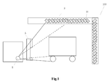
- an inspection system or a safety inspection system 100 comprises: a ray source 1 for emitting ray; a collimator 5 for collimating the ray emitted from the ray source; and a detector 31 for receiving the ray.
- the ray source may comprise an X-ray source, a gamma ray source, a neutron ray source or the like.
- the detector 31 may be mounted on a detector arm 3 which may have a substantially inverted L-shape or any other suitable shapes.
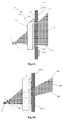
- Figs.2A-2B are schematic views of a collimator 5A according to a first embodiment of the present disclosure.
- the collimator 5A comprises: a collimator body 51 comprising a first part 511, a second part 512 and a collimating slit 52 which is formed between the first part 511 and the second part 512 and has a first end 521 and a second end 522 in a longitudinal direction thereof; and a shielding member 53A which is movable relative to the collimator body 51 to shield at least a part of the collimating slit 52 such that a beam divergent angle of a ray beam 54 propagating through the collimating slit 52 is varied or both a beam divergent angle and an elevation angle of a ray beam 54 propagating through the collimating slit 52 are varied.
- the shielding member 53A comprises a first shielding part 53A1 disposed adjacent to the first end 521 of the collimating slit 52 and a second shielding part 53A2 disposed adjacent to the second end 522 of the collimating slit 52.
- the first shielding part 53A1 and the second shielding part 53A2 are movable relative to the collimator body 51 in the longitudinal direction of the collimating slit, so as to shield at least a part of the collimating slit 52.
- Fig.2A shows that the shielding member is in an initial position, as shown, the first shielding part 53A1 and the second shielding part 53A2 do not shield the collimating slit 52, so that the ray emitted from the ray source 1 propagates through the collimating slit 52 in a totally non-shielded manner so as to form a ray beam 54.
- Fig.2B shows that the shielding member is in a moved position, as shown, the first shielding part 53A1 and the second shielding part 53A2 shield an upper portion and a lower portion of the collimating slit 52, respectively, so that the ray propagates through a remaining portion of the collimating slit 52 so as to form a continuous beam ray, and such a continuous beam ray is labeled as 54' in order to distinguish the two ray beams.
- a beam divergent angle formed between an upmost ray 541 and a lowest ray 542 of the ray beam 54 is labeled as ⁇
- a beam divergent angle formed between an upmost ray 541' and a lowest ray 542' of the ray beam 54' is labeled as ⁇
- the beam divergent angle of the ray beam propagating through the collimating slit refers to the included angle between the upmost ray and the lowest ray of the ray beam propagating through the collimating slit. It can be seen that the inclined angle ⁇ is varied relative to the beam divergent angle ⁇ .
- the beam divergent angle ⁇ can be correspondingly varied as the first shielding part 53A1 and the second shielding part 53A2 move relative to the collimator body 51.
- an elevation angle (which refers to an included angle between the lowest ray of the ray beam propagating through the collimating slit and the horizontal direction) of the ray beam can be also varied correspondingly as the first shielding part 53A1 and the second shielding part 53A2 move relative to the collimator body 51.
- the expression that "the elevation angle is varied” is meant that there is an angle ⁇ (as shown in Fig.2B ) between the lowest ray 542 of the ray beam before being adjusted and the lowest ray 542' of the adjusted ray beam.
- the beam divergent angle of the ray beam propagating through the collimating slit 52 can be controlled or both the beam divergent angle and the elevation angle of the ray beam propagating through the collimating slit 52 can be controlled, also, it can be controlled whether the ray propagates through the collimating slit 52.
- a stepless adjustment of both the beam divergent angle and the elevation angle of the ray beam propagating through the collimating slit 52 can be realized when the first shielding part 53A1 and the second shielding part 53A2 move upward and downward relative to the collimator body 51.
- the beam divergent angle of the ray beam 54 in the initial position as shown in Fig.2A is equal to 50°
- the beam divergent angle of the ray beam 54 can be steplessly adjusted from 50° to 0° as the first shielding part 53A1 and the second shielding part 53A2 move upward and downward relative to the collimator body 51, thereby realizing a beam divergent angle of any values within a range of from 0° to 50°.
- Figs.3A-3D are schematic views of a collimator 5B according to a second embodiment of the present disclosure.
- the same or similar members as that in the first embodiment are labeled as the same or similar reference numerals.
- the second embodiment differs from the first embodiment mainly in the shielding member.
- the collimator 5B comprises a shielding member 53B.
- the shielding member 53B comprises a first shielding part 53B1 disposed at a side of the first part 511 of the collimator body 51 and a second shielding part 53B2 disposed at a side of the second part 512 of the collimator body 51.
- the first shielding part 53B1 and the second shielding part 53B2 each has a multi-stepped structure.
- the first shielding part 53B1 and the second shielding part 53B2 can shield at least a part of the collimating slit 52 as they move leftward and rightward in a direction perpendicular to the longitudinal direction of the collimating slit 52 in Z-plane relative to the collimator body 51.
- Figs.3A-3B show that the shielding member is in an initial position, as shown, the first shielding part 53B 1 and the second shielding part 53B2 do not shield the collimating slit 52, so that the ray emitted from the ray source 1 propagates through the collimating slit 52 in a totally non-shielded manner.
- Figs.3C-3D show that the shielding member is in a moved position, as shown, the first shielding part 53B 1 and the second shielding part 53B2 shield an upper portion and a lower portion of the collimating slit 52, respectively, so that the ray propagates through a remaining portion of the collimating slit 52 so as to form a continuous beam ray, and such a continuous beam ray is labeled as 54' in order to distinguish the two ray beams.
- both the beam divergent angle and the elevation angle of the ray beam propagating through the collimating slit 52 can be controlled, also, it can be controlled whether the ray propagates through the collimating slit 52.
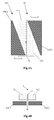
- Figs.4A-4D are schematic views of a collimator 5C according to a third embodiment of the present disclosure.
- the collimator 5C comprises a shielding member 53C.
- the shielding member 53C comprises a first shielding part 53C1 disposed at a side of the first part 511 of the collimator body 51 and a second shielding part 53C2 disposed at a side of the second part 512 of the collimator body 51.
- the first shielding part 53C1 and the second shielding part 53C2 each has a triangular-shaped cross section.
- the first shielding part 53C1 and the second shielding part 53C2 can shield at least a part of the collimating slit 52 in a steplessly adjusting manner as they move leftward and rightward in a direction perpendicular to the longitudinal direction of the collimating slit 52 in Z-plane relative to the collimator body 51, thereby realizing a stepless adjustment of the ray beam propagating through the collimating slit 52.
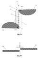
- Figs.5A-5D are schematic views of a collimator 5D according to a fourth embodiment of the present disclosure.
- the same or similar members as that in the first, second and third embodiments are labeled as the same or similar reference numerals.
- the fourth embodiment differs from the above embodiments mainly in a structure and a movement manner of the shielding member.
- the collimator 5D comprises a shielding member 53D.
- the shielding member 53D comprises a first shielding part 53D1 disposed adjacent to the first end 521 of the collimating slit 52 and a second shielding part 53D2 disposed adjacent to the second end 522 of the collimating slit 52.
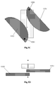
- the first shielding part 53D1 and the second shielding part 53D2 each has a planar plate-like structure having a semi-circular cross section.
- the shielding member 53D comprises a first pivot 53D3 disposed adjacent to the first end 521 of the collimating slit 52 and a second pivot 53D4 disposed adjacent to the second end 522 of the collimating slit 52.
- Axes of the first pivot 53D3 and the second pivot 53D4 both extend in a direction parallel to the Y-plane and perpendicular to the longitudinal direction of the collimating slit 52.
- the first shielding part 53D1 is pivotable about the first pivot 53D3 relative to the collimator body 51 and the second shielding part 53D2 is pivotable about the second pivot 53D4 relative to the collimator body 51.
- the first shielding part 53D1 and the second shielding part 53D2 are spaced from the collimating slit 52 by different distances in a ray propagating direction. In this way, as shown in Figs.5C-5D , the first shielding part 53D1 and the second shielding part 53D2 cannot interfere with each other when they rotate about their respective pivots relative to the collimator body 51, thereby allowing to shield at least a part of the collimating slit 52.
- Figs.6A-6B are schematic views of a collimator 5E according to a fifth embodiment of the present disclosure.
- the same or similar members as that in the first, second, third and fourth embodiments are labeled as the same or similar reference numerals.
- the fifth embodiment differs from the above embodiments mainly in a structure and a movement manner of the shielding member.
- the collimator 5E comprises a shielding member 53E.
- the shielding member 53E comprises a first shielding part 53E1 disposed adjacent to the first end 521 of the collimating slit 52 and a second shielding part 53E2 disposed adjacent to the second end 522 of the collimating slit 52.
- the shielding member 53E comprises a first pivot 53E3 disposed adjacent to the first end 521 of the collimating slit 52 and a second pivot 53E4 disposed adjacent to the second end 522 of the collimating slit 52. Axes of the first pivot 53E3 and the second pivot 53E4 both extend in a direction perpendicular to the beam profile.
- the first shielding part 53E1 is pivotable about the first pivot 53E3 in the Y-plane relative to the collimator body 51 and the second shielding part 53E2 is pivotable about the second pivot 53E4 in the Y-plane relative to the collimator body 51.
- the first shielding part 53E1 and the second shielding part 53E2 can adjust steplessly the beam divergent angle and the elevation angle of the ray beam 54 propagating through the collimating slit 52 as they rotate about their respective pivots relative to the collimator body 51.
- Figs.7A-7B are schematic views of a collimator 5F according to a sixth embodiment of the present disclosure.
- the same or similar members as that in the first, second, third, fourth and fifth embodiments are labeled as the same or similar reference numerals.
- the sixth embodiment differs from the above embodiments mainly in a structure and a movement manner of the shielding member.
- the collimator 5F comprises a shielding member 53F.
- the shielding member 53F comprises a first shielding part 53F1 disposed at a side of the first part 511 of the collimator body 51 and a second shielding part 53F2 disposed at a side of the second part 512 of the collimator body 51.
- the first shielding part 53F1 and the second shielding part 53F2 each may be in a shape of annular cylinder with a special shape, for example, the first shielding part 53F1 and the second shielding part 53F2 each may include a cylindrical portion formed by cutting a portion having at least one corner portion from a small half of an annular cylinder, particularly, the first shielding part 53F1 and the second shielding part 53F2 each may include a cylindrical portion formed by cutting a portion having at least one corner portion from a quarter of an annular cylinder.
- the shielding member 53F comprises a first pivot 53F3 disposed adjacent to the first end 521 of the collimating slit 52 and a second pivot 53F4 disposed adjacent to the second end 522 of the collimating slit 52.
- Axes 53F5, 53F6 of the first pivot 53F3 and the second pivot 53F4 both extend in a direction parallel to the longitudinal direction of the collimating slit 52 in the beam profile Y.
- the first shielding part 53F1 and the second shielding part 53F2 can gradually shield at least a part of the collimating slit 52, thereby allowing to adjust steplessly the beam divergent angle and the elevation angle of the ray beam 54 propagating through the collimating slit 52.
- the shielding member 53 is disposed at a side of the collimator body 51 opposite to the ray source 1, that is, at a side close to an object to be inspected.
- the shielding member 53 may be disposed at a side of the collimator body 51 close to the ray source 1.
- the shielding member 53 may be moved or rotated by hand, or be moved or rotated by a driving mechanism, for example, including a motor and a screw mechanism, or a magnetostrictive mechanism or the like.
- a driving mechanism for example, including a motor and a screw mechanism, or a magnetostrictive mechanism or the like.
- the shielding member 53 may be moved or rotated relative to the collimator body 51 independently from each other, alternatively, may be moved or rotated relative to the collimator body 51 in synchronization with each other.
- the shielding member 53 may be formed of any suitable materials having a ray shielding function, for example, plumbum. Alternatively, one shielding member 53 may have multiple parts formed of materials having different attenuation characteristics.
- the above inspection system can be used to scan a vehicle, that is, to form an inspection system for scanning a vehicle.
- the inspection system is schematically shown in Fig.8 .
- the inspection system 200 for scanning a vehicle comprises: an entrance barrier 201 of a scanning passage configured for allowing a vehicle to be inspected to enter the inspection system; a ray source 202 for emitting ray, such as an accelerator; a collimator (not shown in Fig.8 ) as stated above configured for collimating the ray emitted from the ray source; a detector 203 for receiving the ray; a driving device (not shown) configured for supporting and/or driving the vehicle to be inspected and disposed within an inspected area formed by the collimator and the detector; an operation platform 204 for the driving device; an exit barrier 205 of the scanning passage configured for allowing the inspected vehicle to exit the inspection system; a fence 206 configured for indicating a boundary of a radiation supervised area of the inspection system; and a controller (not shown) configured to be electrically connected to the entrance barrier 201 of the scanning passage, the collimator, the operation platform 204 for the driving device and the exit barrier 205 of the scanning passage.
- a controller not
- the inspection system 200 may further comprise at least one first sensor (not shown) positioned upstream of the inspection system, which is configured for detecting a type of the vehicle 210 to be inspected.
- the vehicle to be inspected may include various types, such as container truck, van truck, small passenger vehicle and the like.
- the controller is electrically connected to the at least one first sensor.
- the inspection system 200 may further comprise at least one second sensor (not shown) positioned upstream of the inspection system, which is configured for detecting a loaded amount in the vehicle 210 to be inspected.
- the controller is electrically connected to the at least one second sensor.
- an inspection method of the above inspection system 200 may comprise steps of:
- the scanning mode comprises a standard scanning mode and a secondary scanning mode.
- the ray propagating through the collimating slit scans the whole vehicle.
- the secondary scanning mode the ray propagating through the collimating slit performs a secondary scan on a suspected area determined through the standard scanning.
- the step of controlling the shielding member of the collimator to move relative to the collimator body based on the selected scanning mode and the measured boundary dose rate may comprise: controlling the shielding member of the collimator to move relative to the collimator body so as to shield at least a part of the ray beam propagating through the collimating slit in the standard scanning mode.
- the shielding member is moved or rotated to shield at least a part of the ray beam propagating through the collimating slit, which allows to reduce the boundary dose rate while keeping an area of the radiation supervised area constant, alternatively, which allows to reduce an area of the radiation supervised area while keeping the boundary dose rate constant.
- the step of controlling the shielding member of the collimator to move relative to the collimator body based on the selected scanning mode and the measured boundary dose rate may comprise: controlling the shielding member of the collimator to move relative to the collimator body while increasing the dose rate and/or an energy of the ray source in the secondary scanning mode, so as to improve an image quality while keeping an area of the radiation supervised area and the boundary dose rate constant.
- first shielding part and the second shielding part can employ the same movement manner.
- first shielding part and the second shielding part can also employ different movement manners, for example, the first shielding part may employ the longitudinal displacement manner while the second shielding part may employ the rotary manner.
- the various movement manners in the above embodiments may be freely combined without conflict, and these combinations should also be included in the scope of the present invention.
Landscapes
- Physics & Mathematics (AREA)
- High Energy & Nuclear Physics (AREA)
- Spectroscopy & Molecular Physics (AREA)
- General Engineering & Computer Science (AREA)
- Engineering & Computer Science (AREA)
- Life Sciences & Earth Sciences (AREA)
- General Physics & Mathematics (AREA)
- Geophysics (AREA)
- Health & Medical Sciences (AREA)
- Biochemistry (AREA)
- General Health & Medical Sciences (AREA)
- Immunology (AREA)
- Pathology (AREA)
- Chemical & Material Sciences (AREA)
- Analytical Chemistry (AREA)
- General Life Sciences & Earth Sciences (AREA)
- Analysing Materials By The Use Of Radiation (AREA)
- Measurement Of Radiation (AREA)
- Apparatus For Radiation Diagnosis (AREA)
- Radiation-Therapy Devices (AREA)
- Radar Systems Or Details Thereof (AREA)
Abstract
Description
- Embodiments of the present disclosure relate to an adjustable collimator and an inspection system, in particular, to an inspection system and an inspection method for scanning a vehicle.
- An inspection system typically uses a ray such as X-ray or the like to inspect an object to be inspected. During such an inspection system is used, it is generally required to ensure an image quality while controlling or supervising exterior radiation, i.e. boundary dose rate.
- In an existing inspection system, the image quality is improved by increasing the dose rate in a case that a radiation protection device and an area of a radiation controlled area are kept unchanged, in such case, the boundary dose rate is inevitably increased. Alternatively, the image quality has to be sacrificed in order to control the boundary dose rate. Thus, there is a contradiction between increasing the image quality and controlling the boundary dose rate. The existing inspection system is not capable of addressing this contradiction well.
- Therefore, it is required to improve the existing inspection system, in order to ensure the image quality while being adapted to a case in which the boundary dose rate should be kept low.
- In order to meet the above requirements, the present disclosure provides an adjustable collimator and an inspection system having the same. Further, the present disclosure provides an inspection system for scanning a vehicle and an inspection method using the inspection system.
- By using the inspection system and the inspection method according to the present disclosure, a collimator can be adjusted as required to vary an inclined angle and an elevation angle of a ray beam, thereby allowing to increase a dose rate of the ray to improve a partial image quality. For example, in the inspection system for scanning a vehicle, ray doses in a region where wheels are located and in empty compartments or air compartments in and above a top of a vehicle container may be restricted to reduce a transmitted dose of the entire system and thus reduce a scattered dose indirectly, thereby achieving an objective of reducing a boundary dose rate; alternatively, to improve an image quality of a suspected area while the radiation supervised area is not enlarged and an original safety standard is kept.
- To this end, according to an aspect of the present disclosure, it is provided a collimator comprising:
- a collimator body comprising a first part, a second part, and a collimating slit formed between the first part and the second part, the collimating slit having a first end and a second end in a longitudinal direction thereof; and
- a shielding member which is movable relative to the collimator body such that a beam divergent angle of a ray beam propagating through the collimating slit is varied or both a beam divergent angle and an elevation angle of a ray beam propagating through the collimating slit are varied.
- In an embodiment, the shielding member is movable relative to the collimator body to completely shield the ray beam propagating through the collimating slit.
- In an embodiment, the shielding member is configured to shield at least a part of the collimating slit as it moves relative to the collimator body, so as to allow the ray propagating through a remaining part of the collimating slit to form a continuous ray beam, the beam divergent angle of the continuous ray beam or both the beam divergent angle and the elevation angle of the continuous ray beam being varied as the shielding member moves relative to the collimator body.
- In an embodiment, the shielding member is capable of adjusting steplessly the beam divergent angle of the ray beam propagating through the collimating slit or both the beam divergent angle and the elevation angle of the ray beam propagating through the collimating slit as the shielding member moves relative to the collimator body.
- In an embodiment, the shielding member comprises a first shielding part which is disposed adjacent to the first end of the collimating slit and is movable in the longitudinal direction of the collimating slit relative to the collimator body; and/or a second shielding part which is disposed adjacent to the second end of the collimating slit and is movable in the longitudinal direction of the collimating slit relative to the collimator body.
- In an embodiment, the shielding member comprises a first shielding part which is disposed at a side of the first part of the collimator body and is movable in a direction perpendicular to the longitudinal direction of the collimating slit in a plane passing through the collimating slit and perpendicular to a beam profile relative to the collimator body; and/or a second shielding part which is disposed at a side of the second part of the collimator body and is movable in a direction perpendicular to the longitudinal direction of the collimating slit in a plane passing through the collimating slit and perpendicular to the beam profile relative to the collimator body.
- In an embodiment, the first shielding part and/or the second shielding part each has a cross section of multi-stepped shape or triangular shape.
- In an embodiment, the shielding member comprises a first shielding part and a first pivot which both are disposed adjacent to the first end of the collimating slit, the first pivot extending in a direction perpendicular to the longitudinal direction of the collimating slit in a plane parallel to a beam profile, the first shielding part being pivotable about the first pivot relative to the collimator body; and/or a second shielding part and a second pivot which both are disposed adjacent to the second end of the collimating slit, the second pivot extending in the direction perpendicular to the longitudinal direction of the collimating slit in the plane parallel to the beam profile, the second shielding part being pivotable about the second pivot relative to the collimator body.
- In an embodiment, the first shielding part and/or the second shielding part each has a planar plate-like structure having a semi-circular cross section.
- In an embodiment, the first shielding part and the second shielding part are spaced from the collimating slit by different distances in a ray propagating direction.
- In an embodiment, the shielding member comprises a first shielding part and a first pivot which both are disposed adjacent to the first end of the collimating slit, an axis of the first pivot extending in a direction perpendicular to a beam profile, the first shielding part being pivotable about the first pivot relative to the collimator body; and/or a second shielding part and a second pivot which both are disposed adjacent to the second end of the collimating slit, the second pivot extending in the direction perpendicular to the beam profile, the second shielding part being pivotable about the second pivot relative to the collimator body.
- In an embodiment, the shielding member comprises a first shielding part which is disposed at a side of the first part of the collimator body and a first pivot which is disposed adjacent to the first end of the collimating slit, an axis of the first pivot extending in a direction parallel to the longitudinal direction of the collimating slit in a plane parallel to a beam profile, the first shielding part being pivotable about the first pivot relative to the collimator body to shield at least a part of the collimating slit; and/or a second shielding part which is disposed at a side of the second part of the collimator body and a second pivot which is disposed adjacent to the second end of the collimating slit, an axis of the second pivot extending in the direction parallel to the longitudinal direction of the collimating slit in the plane parallel to the beam profile, the second shielding part being pivotable about the second pivot relative to the collimator body to shield at least a part of the collimating slit.
- In an embodiment, the first shielding part and/or the second shielding part each is formed by cutting a quarter of an annular cylinder.
- In an embodiment, the first shielding part and the second shielding part are allowed to move relative to the collimator body independently from each other.
- In an embodiment, the first shielding part and the second shielding part are allowed to move relative to the collimator body in synchronization with each other.
- According to another aspect of the present disclosure, it is provided an inspection system comprising:
- a ray source for emitting ray;
- the collimator according to
claim 1 configured for collimating the ray emitted from the ray source; - a detector for receiving the ray; and
- a controller configured to be electrically connected to the collimator and control the shielding member to move relative to the collimator body.
- According to another further aspect of the present disclosure, it is provided an inspection method for scanning a vehicle, comprising steps of:
- selecting a scanning mode;
- emitting ray by a ray source;
- enabling the ray to propagate through a collimating slit of a collimator so as to form a ray beam;
- measuring a boundary dose rate of a radiation supervised area; and
- controlling a shielding member of the collimator to move relative to a collimator body based on the selected scanning mode and the measured boundary dose rate.
- In an embodiment, the scanning mode comprises a standard scanning mode in which the ray propagating through the collimating slit scans the whole vehicle and a secondary scanning mode in which the ray propagating through the collimating slit performs a secondary scan on a suspected area determined through the standard scanning.
- In an embodiment, the step of controlling a shielding member of the collimator to move relative to a collimator body based on the selected scanning mode and the measured boundary dose rate comprises:
- controlling the shielding member of the collimator to move relative to the collimator body so as to shield at least a part of the ray beam propagating through the collimating slit in the standard scanning mode.
- In an embodiment, the step of controlling a shielding member of the collimator to move relative to a collimator body based on the selected scanning mode and the measured boundary dose rate comprises: controlling the shielding member of the collimator to move relative to the collimator body while increasing the dose rate and/or an energy of the ray source in the secondary scanning mode, so as to improve an image quality while keeping an area of the radiation supervised area and the boundary dose rate constant.
- The collimator, the inspection system and the inspection method according to the embodiments of the present disclosure may be applied in the following various cases and achieve the following effects:
- (1) in the standard scanning mode, the shielding member is moved or rotated to shield at least a part of the ray beam propagating through the collimating slit, which allows to reduce the boundary dose rate while keeping an area of the radiation supervised area constant, alternatively, which allows to reduce an area of the radiation supervised area while keeping the boundary dose rate constant;
- (2) in the secondary scanning mode, controlling the shielding member of the collimator to move relative to the collimator body while increasing the dose rate and/or an energy of the ray source so as to improve an image quality while keeping an area of the radiation supervised area and the boundary dose rate constant.
-
-
Fig.1 is a schematic view showing that an inspection system according to an embodiment of the present disclosure is in a scanning state; -
Fig.2A is a schematic view of a collimator according to a first embodiment of the present disclosure, in which the collimator is in an initial position in which it does not shield a ray beam; -
Fig.2B is a schematic view of the collimator according to the first embodiment of the present disclosure, in which the collimator is in a moved position in which it shields a part of the ray beam; -
Fig.3A is a schematic front view of a collimator according to a second embodiment of the present disclosure, in which the collimator is in an initial position in which it does not shield a ray beam; -
Fig.3B is a schematic top view of the collimator according to the second embodiment of the present disclosure, in which the collimator is in an initial position in which it does not shield a ray beam; -
Fig.3C is a schematic front view of the collimator according to the second embodiment of the present disclosure, in which the collimator is in a moved position in which it shields a part of the ray beam; -
Fig.3D is a schematic top view of the collimator according to the second embodiment of the present disclosure, in which the collimator is in a moved position in which it shields a part of the ray beam; -
Fig.4A is a schematic front view of a collimator according to a third embodiment of the present disclosure, in which the collimator is in an initial position in which it does not shield a ray beam; -
Fig.4B is a schematic top view of the collimator according to the third embodiment of the present disclosure, in which the collimator is in an initial position in which it does not shield a ray beam; -
Fig.4C is a schematic front view of the collimator according to the third embodiment of the present disclosure, in which the collimator is in a moved position in which it shields a part of the ray beam; -
Fig.4D is a schematic top view of the collimator according to the third embodiment of the present disclosure, in which the collimator is in a moved position in which it shields a part of the ray beam; -
Fig.5A is a schematic front view of a collimator according to a fourth embodiment of the present disclosure, in which the collimator is in an initial position in which it does not shield a ray beam; -
Fig.5B is a schematic top view of the collimator according to the fourth embodiment of the present disclosure, in which the collimator is in an initial position in which it does not shield a ray beam; -
Fig.5C is a schematic front view of the collimator according to the fourth embodiment of the present disclosure, in which the collimator is in a rotated position in which it shields a part of the ray beam; -
Fig.5D is a schematic top view of the collimator according to the fourth embodiment of the present disclosure, in which the collimator is in a rotated position in which it shields a part of the ray beam; -
Fig.6A is a schematic view of a collimator according to a fifth embodiment of the present disclosure, in which the collimator is in an initial position in which it does not shield a ray beam; -
Fig.6B is a schematic view of the collimator according to the fifth embodiment of the present disclosure, in which the collimator is in a rotated position in which it shields a part of the ray beam; -
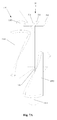
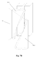
Fig.7A is a schematic view of a collimator according to a sixth embodiment of the present disclosure, in which the collimator is in an initial position in which it does not shield a ray beam; -
Fig.7B is a schematic view of the collimator according to the sixth embodiment of the present disclosure, in which the collimator is in a rotated position in which it shields a part of the ray beam; and -
Fig.8 is a schematic view of an inspection system for scanning a vehicle according to an embodiment of the present disclosure. - First of all, it is necessary to explain and define the following terms and expressions for ease of description and understanding.
- A term "radiation controlled area" refers to an area divided from a radiation workplace, in which a specialized protection means and safety measure is required or possibly required in order to: (a) control a normal irradiation or prevent a dispersal of pollution in a normal working condition; and (b) prevent a potential irradiation or limit a degree thereof.
- A term "radiation supervised area" refers to an area which is not determined as the radiation controlled area and in which a specialized protection means and safety measure is normally not required but it is required to supervise continuously the irradiation condition therein.
- An expression "beam profile" refers to a cross section of a ray beam emitted from a collimating slit of a collimator along a propagating direction of the ray beam.
- An expression "Y-plane" refers to a plane which is coincident with the beam profile.
- An expression "Z-plane" refers to a plane which is perpendicular to the Y-plane and passes through the collimating slit.
- An expression "X-plane" refers to a plane which is perpendicular to the Y-plane and the collimating slit.
- Next, specific embodiments of the present disclosure will be explained with reference to the accompanying drawings.
- Referring to
Fig.1 , an inspection system or asafety inspection system 100 according to an embodiment of the present disclosure comprises: aray source 1 for emitting ray; acollimator 5 for collimating the ray emitted from the ray source; and adetector 31 for receiving the ray. The ray source may comprise an X-ray source, a gamma ray source, a neutron ray source or the like. Thedetector 31 may be mounted on adetector arm 3 which may have a substantially inverted L-shape or any other suitable shapes. -
Figs.2A-2B are schematic views of acollimator 5A according to a first embodiment of the present disclosure. As shown, thecollimator 5A comprises: acollimator body 51 comprising afirst part 511, asecond part 512 and a collimating slit 52 which is formed between thefirst part 511 and thesecond part 512 and has afirst end 521 and asecond end 522 in a longitudinal direction thereof; and a shieldingmember 53A which is movable relative to thecollimator body 51 to shield at least a part of the collimating slit 52 such that a beam divergent angle of aray beam 54 propagating through the collimating slit 52 is varied or both a beam divergent angle and an elevation angle of aray beam 54 propagating through the collimating slit 52 are varied. - Specifically, as shown in
Figs.2A-2B , the shieldingmember 53A comprises a first shielding part 53A1 disposed adjacent to thefirst end 521 of the collimating slit 52 and a second shielding part 53A2 disposed adjacent to thesecond end 522 of the collimating slit 52. The first shielding part 53A1 and the second shielding part 53A2 are movable relative to thecollimator body 51 in the longitudinal direction of the collimating slit, so as to shield at least a part of the collimating slit 52.Fig.2A shows that the shielding member is in an initial position, as shown, the first shielding part 53A1 and the second shielding part 53A2 do not shield the collimating slit 52, so that the ray emitted from theray source 1 propagates through the collimating slit 52 in a totally non-shielded manner so as to form aray beam 54.Fig.2B shows that the shielding member is in a moved position, as shown, the first shielding part 53A1 and the second shielding part 53A2 shield an upper portion and a lower portion of the collimating slit 52, respectively, so that the ray propagates through a remaining portion of the collimating slit 52 so as to form a continuous beam ray, and such a continuous beam ray is labeled as 54' in order to distinguish the two ray beams. As shown inFigs.2A and Fig.2B , a beam divergent angle formed between anupmost ray 541 and alowest ray 542 of theray beam 54 is labeled as α, and a beam divergent angle formed between an upmost ray 541' and a lowest ray 542' of the ray beam 54' is labeled as β. In other words, the beam divergent angle of the ray beam propagating through the collimating slit refers to the included angle between the upmost ray and the lowest ray of the ray beam propagating through the collimating slit. It can be seen that the inclined angle β is varied relative to the beam divergent angle α. Further, as shown, the beam divergent angle β can be correspondingly varied as the first shielding part 53A1 and the second shielding part 53A2 move relative to thecollimator body 51. Meanwhile, an elevation angle (which refers to an included angle between the lowest ray of the ray beam propagating through the collimating slit and the horizontal direction) of the ray beam can be also varied correspondingly as the first shielding part 53A1 and the second shielding part 53A2 move relative to thecollimator body 51. Herein, the expression that "the elevation angle is varied" is meant that there is an angle γ (as shown inFig.2B ) between thelowest ray 542 of the ray beam before being adjusted and the lowest ray 542' of the adjusted ray beam. When the first shielding part 53A1 and the second shielding part 53A2 further move to shield the collimating slit 52 fully, the ray emitted from theray source 1 is totally shielded. Thus, by controlling the first shielding part 53A1 and the second shielding part 53A2 to move relative to thecollimator body 51, the beam divergent angle of the ray beam propagating through the collimating slit 52 can be controlled or both the beam divergent angle and the elevation angle of the ray beam propagating through the collimating slit 52 can be controlled, also, it can be controlled whether the ray propagates through the collimating slit 52. - It should be appreciated by those skilled in the art that a stepless adjustment of both the beam divergent angle and the elevation angle of the ray beam propagating through the collimating slit 52 can be realized when the first shielding part 53A1 and the second shielding part 53A2 move upward and downward relative to the
collimator body 51. For example, if the beam divergent angle of theray beam 54 in the initial position as shown inFig.2A is equal to 50°, the beam divergent angle of theray beam 54 can be steplessly adjusted from 50° to 0° as the first shielding part 53A1 and the second shielding part 53A2 move upward and downward relative to thecollimator body 51, thereby realizing a beam divergent angle of any values within a range of from 0° to 50°. -
Figs.3A-3D are schematic views of acollimator 5B according to a second embodiment of the present disclosure. In this embodiment, the same or similar members as that in the first embodiment are labeled as the same or similar reference numerals. The second embodiment differs from the first embodiment mainly in the shielding member. - The
collimator 5B comprises a shieldingmember 53B. Specifically, as shown inFig.3A , the shieldingmember 53B comprises a first shielding part 53B1 disposed at a side of thefirst part 511 of thecollimator body 51 and a second shielding part 53B2 disposed at a side of thesecond part 512 of thecollimator body 51. As shown, the first shielding part 53B1 and the second shielding part 53B2 each has a multi-stepped structure. In this way, the first shielding part 53B1 and the second shielding part 53B2 can shield at least a part of the collimating slit 52 as they move leftward and rightward in a direction perpendicular to the longitudinal direction of the collimating slit 52 in Z-plane relative to thecollimator body 51. -
Figs.3A-3B show that the shielding member is in an initial position, as shown, thefirst 1 and the second shielding part 53B2 do not shield the collimating slit 52, so that the ray emitted from theshielding part 53Bray source 1 propagates through the collimating slit 52 in a totally non-shielded manner.Figs.3C-3D show that the shielding member is in a moved position, as shown, thefirst 1 and the second shielding part 53B2 shield an upper portion and a lower portion of the collimating slit 52, respectively, so that the ray propagates through a remaining portion of the collimating slit 52 so as to form a continuous beam ray, and such a continuous beam ray is labeled as 54' in order to distinguish the two ray beams. Thus, it should be appreciated by those skilled in the art that, by controlling the first shielding part 53B1 and the second shielding part 53B2 to move relative to theshielding part 53Bcollimator body 51, both the beam divergent angle and the elevation angle of the ray beam propagating through the collimating slit 52 can be controlled, also, it can be controlled whether the ray propagates through the collimating slit 52. -
Figs.4A-4D are schematic views of acollimator 5C according to a third embodiment of the present disclosure. In this embodiment, the same or similar members as that in the first and second embodiments are labeled as the same or similar reference numerals. The third embodiment differs from the second embodiment mainly in the shape of the shielding member. Thecollimator 5C comprises a shieldingmember 53C. As shown inFigs.4A-4D , the shieldingmember 53C comprises a first shielding part 53C1 disposed at a side of thefirst part 511 of thecollimator body 51 and a second shielding part 53C2 disposed at a side of thesecond part 512 of thecollimator body 51. As shown, differing from the multi-stepped shape in the second embodiment, the first shielding part 53C1 and the second shielding part 53C2 each has a triangular-shaped cross section. In this way, the first shielding part 53C1 and the second shielding part 53C2 can shield at least a part of the collimating slit 52 in a steplessly adjusting manner as they move leftward and rightward in a direction perpendicular to the longitudinal direction of the collimating slit 52 in Z-plane relative to thecollimator body 51, thereby realizing a stepless adjustment of the ray beam propagating through the collimating slit 52. -
Figs.5A-5D are schematic views of acollimator 5D according to a fourth embodiment of the present disclosure. In this embodiment, the same or similar members as that in the first, second and third embodiments are labeled as the same or similar reference numerals. The fourth embodiment differs from the above embodiments mainly in a structure and a movement manner of the shielding member. - The
collimator 5D comprises a shieldingmember 53D. Specifically, as shown inFig.5A , the shieldingmember 53D comprises a first shielding part 53D1 disposed adjacent to thefirst end 521 of the collimating slit 52 and a second shielding part 53D2 disposed adjacent to thesecond end 522 of the collimating slit 52. As shown, the first shielding part 53D1 and the second shielding part 53D2 each has a planar plate-like structure having a semi-circular cross section. Further, the shieldingmember 53D comprises a first pivot 53D3 disposed adjacent to thefirst end 521 of the collimating slit 52 and a second pivot 53D4 disposed adjacent to thesecond end 522 of the collimating slit 52. Axes of the first pivot 53D3 and the second pivot 53D4 both extend in a direction parallel to the Y-plane and perpendicular to the longitudinal direction of the collimating slit 52. In this way, the first shielding part 53D1 is pivotable about the first pivot 53D3 relative to thecollimator body 51 and the second shielding part 53D2 is pivotable about the second pivot 53D4 relative to thecollimator body 51. - Also, as shown in
Fig.5B , the first shielding part 53D1 and the second shielding part 53D2 are spaced from the collimating slit 52 by different distances in a ray propagating direction. In this way, as shown inFigs.5C-5D , the first shielding part 53D1 and the second shielding part 53D2 cannot interfere with each other when they rotate about their respective pivots relative to thecollimator body 51, thereby allowing to shield at least a part of the collimating slit 52. -
Figs.6A-6B are schematic views of acollimator 5E according to a fifth embodiment of the present disclosure. In this embodiment, the same or similar members as that in the first, second, third and fourth embodiments are labeled as the same or similar reference numerals. The fifth embodiment differs from the above embodiments mainly in a structure and a movement manner of the shielding member. - The
collimator 5E comprises a shieldingmember 53E. Specifically, as shown inFig.6A , the shieldingmember 53E comprises a first shielding part 53E1 disposed adjacent to thefirst end 521 of the collimating slit 52 and a second shielding part 53E2 disposed adjacent to thesecond end 522 of the collimating slit 52. Further, the shieldingmember 53E comprises a first pivot 53E3 disposed adjacent to thefirst end 521 of the collimating slit 52 and a second pivot 53E4 disposed adjacent to thesecond end 522 of the collimating slit 52. Axes of the first pivot 53E3 and the second pivot 53E4 both extend in a direction perpendicular to the beam profile. - In this way, the first shielding part 53E1 is pivotable about the first pivot 53E3 in the Y-plane relative to the
collimator body 51 and the second shielding part 53E2 is pivotable about the second pivot 53E4 in the Y-plane relative to thecollimator body 51. Thus, as shown inFig.6B , the first shielding part 53E1 and the second shielding part 53E2 can adjust steplessly the beam divergent angle and the elevation angle of theray beam 54 propagating through the collimating slit 52 as they rotate about their respective pivots relative to thecollimator body 51. -
Figs.7A-7B are schematic views of acollimator 5F according to a sixth embodiment of the present disclosure. In this embodiment, the same or similar members as that in the first, second, third, fourth and fifth embodiments are labeled as the same or similar reference numerals. The sixth embodiment differs from the above embodiments mainly in a structure and a movement manner of the shielding member. - The
collimator 5F comprises a shieldingmember 53F. Specifically, as shown inFig.7A , the shieldingmember 53F comprises a first shielding part 53F1 disposed at a side of thefirst part 511 of thecollimator body 51 and a second shielding part 53F2 disposed at a side of thesecond part 512 of thecollimator body 51. As shown, the first shielding part 53F1 and the second shielding part 53F2 each may be in a shape of annular cylinder with a special shape, for example, the first shielding part 53F1 and the second shielding part 53F2 each may include a cylindrical portion formed by cutting a portion having at least one corner portion from a small half of an annular cylinder, particularly, the first shielding part 53F1 and the second shielding part 53F2 each may include a cylindrical portion formed by cutting a portion having at least one corner portion from a quarter of an annular cylinder. - Further, the shielding
member 53F comprises a first pivot 53F3 disposed adjacent to thefirst end 521 of the collimating slit 52 and a second pivot 53F4 disposed adjacent to thesecond end 522 of the collimating slit 52. Axes 53F5, 53F6 of the first pivot 53F3 and the second pivot 53F4 both extend in a direction parallel to the longitudinal direction of the collimating slit 52 in the beam profile Y. - In this way, as shown in
Fig.7B , as the first shielding part 53F1 and the second shielding part 53F2 rotate about their respective pivots relative to thecollimator body 51, the first shielding part 53F1 and the second shielding part 53F2 can gradually shield at least a part of the collimating slit 52, thereby allowing to adjust steplessly the beam divergent angle and the elevation angle of theray beam 54 propagating through the collimating slit 52. - In the above embodiments, the shielding member 53 is disposed at a side of the
collimator body 51 opposite to theray source 1, that is, at a side close to an object to be inspected. Alternatively, the shielding member 53 may be disposed at a side of thecollimator body 51 close to theray source 1. - In the above embodiments, the shielding member 53 may be moved or rotated by hand, or be moved or rotated by a driving mechanism, for example, including a motor and a screw mechanism, or a magnetostrictive mechanism or the like.
- In the above embodiments, the shielding member 53 may be moved or rotated relative to the
collimator body 51 independently from each other, alternatively, may be moved or rotated relative to thecollimator body 51 in synchronization with each other. - In the above embodiments, the shielding member 53 may be formed of any suitable materials having a ray shielding function, for example, plumbum. Alternatively, one shielding member 53 may have multiple parts formed of materials having different attenuation characteristics.
- According to another aspect of the present disclosure, the above inspection system can be used to scan a vehicle, that is, to form an inspection system for scanning a vehicle. The inspection system is schematically shown in
Fig.8 . - The
inspection system 200 for scanning a vehicle comprises: anentrance barrier 201 of a scanning passage configured for allowing a vehicle to be inspected to enter the inspection system; aray source 202 for emitting ray, such as an accelerator; a collimator (not shown inFig.8 ) as stated above configured for collimating the ray emitted from the ray source; adetector 203 for receiving the ray; a driving device (not shown) configured for supporting and/or driving the vehicle to be inspected and disposed within an inspected area formed by the collimator and the detector; anoperation platform 204 for the driving device; anexit barrier 205 of the scanning passage configured for allowing the inspected vehicle to exit the inspection system; afence 206 configured for indicating a boundary of a radiation supervised area of the inspection system; and a controller (not shown) configured to be electrically connected to theentrance barrier 201 of the scanning passage, the collimator, theoperation platform 204 for the driving device and theexit barrier 205 of the scanning passage. InFig.8 , the vehicle to be inspected is indicated by 210. - Optionally, the
inspection system 200 may further comprise at least one first sensor (not shown) positioned upstream of the inspection system, which is configured for detecting a type of thevehicle 210 to be inspected. For example, the vehicle to be inspected may include various types, such as container truck, van truck, small passenger vehicle and the like. Moreover, the controller is electrically connected to the at least one first sensor. - Optionally, the
inspection system 200 may further comprise at least one second sensor (not shown) positioned upstream of the inspection system, which is configured for detecting a loaded amount in thevehicle 210 to be inspected. Moreover, the controller is electrically connected to the at least one second sensor. - According to another further aspect of the present disclosure, an inspection method of the
above inspection system 200 may comprise steps of: - selecting a scanning mode;
- emitting ray by the ray source;
- enabling the ray to propagate through the collimating slit of the collimator so as to form a ray beam;
- measuring a boundary dose rate of a radiation supervised area; and
- controlling the shielding member of the collimator to move relative to the collimator body based on the selected scanning mode and the measured boundary dose rate.
- In an embodiment, the scanning mode comprises a standard scanning mode and a secondary scanning mode. In the standard scanning mode, the ray propagating through the collimating slit scans the whole vehicle. In the secondary scanning mode, the ray propagating through the collimating slit performs a secondary scan on a suspected area determined through the standard scanning.
- In an embodiment, the step of controlling the shielding member of the collimator to move relative to the collimator body based on the selected scanning mode and the measured boundary dose rate may comprise: controlling the shielding member of the collimator to move relative to the collimator body so as to shield at least a part of the ray beam propagating through the collimating slit in the standard scanning mode. As a result, in the standard scanning mode, the shielding member is moved or rotated to shield at least a part of the ray beam propagating through the collimating slit, which allows to reduce the boundary dose rate while keeping an area of the radiation supervised area constant, alternatively, which allows to reduce an area of the radiation supervised area while keeping the boundary dose rate constant.
- In an embodiment, the step of controlling the shielding member of the collimator to move relative to the collimator body based on the selected scanning mode and the measured boundary dose rate may comprise: controlling the shielding member of the collimator to move relative to the collimator body while increasing the dose rate and/or an energy of the ray source in the secondary scanning mode, so as to improve an image quality while keeping an area of the radiation supervised area and the boundary dose rate constant.
- In the above embodiments, various movement manners including longitudinal displacement, lateral displacement, rotation about different axes and the like are included. The first shielding part and the second shielding part can employ the same movement manner. However, it should be appreciated by those skilled in the art that the first shielding part and the second shielding part can also employ different movement manners, for example, the first shielding part may employ the longitudinal displacement manner while the second shielding part may employ the rotary manner. In other words, the various movement manners in the above embodiments may be freely combined without conflict, and these combinations should also be included in the scope of the present invention.
- The objectives, solutions and effects have been explained in detail by means of the above specific embodiments. It should be understood that the above description is merely some specific embodiments of the present invention, rather than limiting the present invention. Any modifications, equivalents and changes within the spirit and principle of the present invention shall fall into the scope of the present invention.
Claims (15)
- A collimator (5) comprising:a collimator body (51) comprising a first part (511), a second part (512), and a collimating slit (52) formed between the first part and the second part, the collimating slit having a first end (521) and a second end (522) in a longitudinal direction thereof; anda shielding member (53) which is movable relative to the collimator body such that a beam divergent angle ( α ) of a ray beam (54) propagating through the collimating slit is varied or both a beam divergent angle ( α ) and an elevation angle ( γ ) of a ray beam propagating through the collimating slit are varied.
- The collimator according to claim 1, wherein the shielding member (53) is movable relative to the collimator body (51) to completely shield the ray beam (54) propagating through the collimating slit.
- The collimator according to claim 1, wherein the shielding member (53) is configured to shield at least a part of the collimating slit (52) as it moves relative to the collimator body, so as to allow the ray propagating through a remaining part of the collimating slit to form a continuous ray beam (54'), the beam divergent angle ( β ) of the continuous ray beam or both the beam divergent angle ( β ) and the elevation angle ( γ ) of the continuous ray beam being varied as the shielding member (53) moves relative to the collimator body (51).
- The collimator according to claim 1 or 3, wherein the shielding member (53) is capable of adjusting steplessly the beam divergent angle ( β ) of the ray beam (54) propagating through the collimating slit (52) or both the beam divergent angle ( β ) and the elevation angle ( γ ) of the ray beam (54) propagating through the collimating slit (52) as the shielding member (53) moves relative to the collimator body (51).
- The collimator according to any one of claims 1-3, wherein the shielding member (53) comprises a first shielding part (53A1) which is disposed adjacent to the first end (521) of the collimating slit and is movable in the longitudinal direction of the collimating slit relative to the collimator body; and/or a second shielding part (53A2) which is disposed adjacent to the second end (522) of the collimating slit and is movable in the longitudinal direction of the collimating slit relative to the collimator body.
- The collimator according to any one of claims 1-3, wherein the shielding member comprises a first shielding part (53B1, 53C1) which is disposed at a side of the first part (511) of the collimator body and is movable in a direction perpendicular to the longitudinal direction of the collimating slit in a plane passing through the collimating slit and perpendicular to a beam profile relative to the collimator body; and/or a second shielding part (53B2, 53C2) which is disposed at a side of the second part (512) of the collimator body and is movable in a direction perpendicular to the longitudinal direction of the collimating slit in a plane passing through the collimating slit and perpendicular to the beam profile relative to the collimator body, preferably, the first shielding part and/or the second shielding part each has a cross section of multi-stepped shape or triangular shape.
- The collimator according to any one of claims 1-3, wherein the shielding member comprises a first shielding part (53D1) and a first pivot (53D3) which both are disposed adjacent to the first end (521) of the collimating slit, the first pivot extending in a direction perpendicular to the longitudinal direction of the collimating slit in a plane parallel to a beam profile, the first shielding part being pivotable about the first pivot relative to the collimator body; and/or a second shielding part (53D2) and a second pivot (53D4) which both are disposed adjacent to the second end (522) of the collimating slit, the second pivot extending in the direction perpendicular to the longitudinal direction of the collimating slit in the plane parallel to the beam profile, the second shielding part being pivotable about the second pivot relative to the collimator body, preferably, the first shielding part and/or the second shielding part each has a planar plate-like structure having a semi-circular cross section; and more preferably, the first shielding part and the second shielding part are spaced from the collimating slit by different distances in a ray propagating direction.
- The collimator according to any one of claims 1-3, wherein the shielding member comprises a first shielding part (53E1) and a first pivot (53E3) which both are disposed adjacent to the first end (521) of the collimating slit, an axis of the first pivot extending in a direction perpendicular to a beam profile, the first shielding part being pivotable about the first pivot relative to the collimator body; and/or a second shielding part (53E2) and a second pivot (53E4) which both are disposed adjacent to the second end (522) of the collimating slit, the second pivot extending in the direction perpendicular to the beam profile, the second shielding part being pivotable about the second pivot relative to the collimator body.
- The collimator according to any one of claims 1-3, wherein the shielding member comprises a first shielding part (53F1) which is disposed at a side of the first part (511) of the collimator body and a first pivot (53F3) which is disposed adjacent to the first end (521) of the collimating slit, an axis of the first pivot extending in a direction parallel to the longitudinal direction of the collimating slit in a plane parallel to a beam profile, the first shielding part being pivotable about the first pivot relative to the collimator body to shield at least a part of the collimating slit; and/or a second shielding part (53F2) which is disposed at a side of the second part (512) of the collimator body and a second pivot (53F4) which is disposed adjacent to the second end (522) of the collimating slit, an axis of the second pivot extending in the direction parallel to the longitudinal direction of the collimating slit in the plane parallel to the beam profile, the second shielding part being pivotable about the second pivot relative to the collimator body to shield at least a part of the collimating slit; preferably, the first shielding part and/or the second shielding part each is formed by cutting a quarter of an annular cylinder.
- The collimator according to any one of claims 5-9, wherein the first shielding part and the second shielding part are allowed to move relative to the collimator body independently from each other, or the first shielding part and the second shielding part are allowed to move relative to the collimator body in synchronization with each other.
- An inspection system comprising:a ray source (1) for emitting ray;the collimator (5) according to any one of claims 1-10 configured for collimating the ray emitted from the ray source;a detector (31) for receiving the ray; anda controller configured to be electrically connected to the collimator and control the shielding member to move relative to the collimator body.
- An inspection method for scanning a vehicle, comprising steps of:selecting a scanning mode;emitting ray by a ray source;enabling the ray to propagate through a collimating slit of a collimator so as to form a ray beam;measuring a boundary dose rate of a radiation supervised area; andcontrolling a shielding member of the collimator to move relative to a collimator body based on the selected scanning mode and the measured boundary dose rate.
- The inspection method according to claim 12, wherein the scanning mode comprises a standard scanning mode in which the ray propagating through the collimating slit scans the whole vehicle and a secondary scanning mode in which the ray propagating through the collimating slit performs a secondary scan on a suspected area determined through the standard scanning.
- The inspection method according to claim 13, wherein the step of controlling a shielding member of the collimator to move relative to a collimator body based on the selected scanning mode and the measured boundary dose rate comprises:controlling the shielding member of the collimator to move relative to the collimator body so as to shield at least a part of the ray beam propagating through the collimating slit in the standard scanning mode.
- The inspection method according to claim 13 or 14, wherein the step of controlling a shielding member of the collimator to move relative to a collimator body based on the selected scanning mode and the measured boundary dose rate comprises: controlling the shielding member of the collimator to move relative to the collimator body while increasing the dose rate and/or an energy of the ray source in the secondary scanning mode, so as to improve an image quality while keeping an area of the radiation supervised area and the boundary dose rate constant.
Priority Applications (1)
| Application Number | Priority Date | Filing Date | Title |
|---|---|---|---|
| PL16191080T PL3188194T3 (en) | 2015-12-28 | 2016-09-28 | Collimator and inspection system having the same |
Applications Claiming Priority (1)
| Application Number | Priority Date | Filing Date | Title |
|---|---|---|---|
| CN201511001491.2A CN105403580B (en) | 2015-12-28 | 2015-12-28 | Collimator and inspection system |
Publications (3)
| Publication Number | Publication Date |
|---|---|
| EP3188194A2 true EP3188194A2 (en) | 2017-07-05 |
| EP3188194A3 EP3188194A3 (en) | 2017-11-15 |
| EP3188194B1 EP3188194B1 (en) | 2020-09-02 |
Family
ID=55469200
Family Applications (1)
| Application Number | Title | Priority Date | Filing Date |
|---|---|---|---|
| EP16191080.7A Active EP3188194B1 (en) | 2015-12-28 | 2016-09-28 | Collimator and inspection system having the same |
Country Status (9)
| Country | Link |
|---|---|
| US (1) | US10658088B2 (en) |
| EP (1) | EP3188194B1 (en) |
| CN (1) | CN105403580B (en) |
| BR (1) | BR112017025677B1 (en) |
| EA (1) | EA201792410A1 (en) |
| MY (1) | MY198131A (en) |
| PL (1) | PL3188194T3 (en) |
| SG (1) | SG11201709938UA (en) |
| WO (1) | WO2017113834A1 (en) |
Families Citing this family (16)
| Publication number | Priority date | Publication date | Assignee | Title |
|---|---|---|---|---|
| CN105403580B (en) | 2015-12-28 | 2018-10-09 | 清华大学 | Collimator and inspection system |
| CN105903124B (en) * | 2016-06-30 | 2019-08-13 | 东软医疗系统股份有限公司 | a collimator |
| CN106841249A (en) * | 2017-04-12 | 2017-06-13 | 北京君和信达科技有限公司 | Transmission-type radiation image-forming system |
| CN107807137A (en) * | 2017-10-25 | 2018-03-16 | 同方威视技术股份有限公司 | Front collimator and scanning imaging equipment |
| CN107796838B (en) * | 2017-10-25 | 2024-09-20 | 同方威视技术股份有限公司 | Post-collimator and scanning imaging device |
| CN108375592A (en) * | 2018-03-27 | 2018-08-07 | 许昌瑞示电子科技有限公司 | Ray detector and system, mounting bracket, crossbeam, collimator and its component |
| CN109273131B (en) * | 2018-10-31 | 2024-07-02 | 同方威视技术股份有限公司 | Collimator assembly and radiation detection device |
| CN109659061B (en) * | 2018-12-27 | 2020-06-23 | 中国原子能科学研究院 | Neutron collimator structure with continuously adjustable divergence angle and calibration method thereof |
| KR20220062040A (en) | 2019-09-12 | 2022-05-13 | 올쏘스캔 인코포레이티드 | Mini C-Arm Imaging System with Stepless Collimation |
| CN111407304B (en) * | 2020-03-31 | 2020-11-13 | 汕头市超声仪器研究所有限公司 | Shielding collimation structure of X-ray source |
| CN111773558B (en) * | 2020-07-01 | 2021-05-11 | 苏州雷泰医疗科技有限公司 | A method, apparatus and radiotherapy equipment using grating servo dose rate |
| KR102876076B1 (en) * | 2020-12-09 | 2025-10-23 | 한국해양과학기술원 | Radiation collimating system |
| CN114764071B (en) * | 2020-12-31 | 2025-09-09 | 同方威视技术股份有限公司 | Radiation emitting device and radiation inspection apparatus |
| CN112890845A (en) * | 2021-03-31 | 2021-06-04 | 武汉联影生命科学仪器有限公司 | CT collimating device and CT equipment with same |
| CN115798775A (en) * | 2021-09-09 | 2023-03-14 | 同方威视技术股份有限公司 | Radiation collimation equipment and radiation inspection equipment |
| US20250325240A1 (en) * | 2024-04-17 | 2025-10-23 | United Imaging Healthcare North America, Inc. | Imaging systems, methods, and apparatus thereof |
Family Cites Families (21)
| Publication number | Priority date | Publication date | Assignee | Title |
|---|---|---|---|---|
| US2570820A (en) | 1950-05-29 | 1951-10-09 | Philips Lab Inc | X-ray cone assembly |
| US3151245A (en) * | 1961-11-21 | 1964-09-29 | High Voltage Engineering Corp | X-ray beam collimating apparatus |
| US3829701A (en) * | 1973-01-29 | 1974-08-13 | Picker Corp | Radiation collimator |
| FR2524655B1 (en) * | 1982-04-02 | 1985-10-18 | Cgr Mev | PARTIAL LIMITING BLOCK OF A RADIATION BEAM AND COLLIMATOR COMPRISING SUCH BLOCKS |
| US5165106A (en) * | 1991-06-06 | 1992-11-17 | Siemens Medical Laboratories, Inc. | Contour collimator |
| US5493596A (en) * | 1993-11-03 | 1996-02-20 | Annis; Martin | High-energy X-ray inspection system |
| US5666393A (en) * | 1994-02-17 | 1997-09-09 | Annis; Martin | Method and apparatus for reducing afterglow noise in an X-ray inspection system |
| US5748703A (en) * | 1994-03-22 | 1998-05-05 | Cosman; Eric R. | Dynamic collimator for a linear accelerator |
| JPH11248650A (en) * | 1998-03-06 | 1999-09-17 | Mac Science:Kk | X-ray diffraction microscope device |
| DE10244898B4 (en) | 2002-09-26 | 2010-04-29 | Siemens Ag | Insertion device and computed tomography device with a radiator-side insertion device |
| WO2008110977A1 (en) * | 2007-03-13 | 2008-09-18 | Philips Intellectual Property & Standards Gmbh | Add-on-x-ray-collimator for non-symmetrical beam collimation |
| US20080298546A1 (en) | 2007-05-31 | 2008-12-04 | General Electric Company | Cargo container inspection method |
| CA2723719A1 (en) * | 2008-05-08 | 2009-11-12 | L-3 Communications Security And Detection Systems, Inc. | Adaptive scanning in an imaging system |
| US20100119033A1 (en) * | 2008-11-12 | 2010-05-13 | The Methodist Hospital Research Institute | Intensity-modulated, cone-beam computed tomographic imaging system, methods, and apparatus |
| RU2393633C1 (en) | 2009-03-10 | 2010-06-27 | Открытое акционерное общество "Концерт "Созвездие" | Device for turbo codes decoding |
| JP2012007935A (en) * | 2010-06-23 | 2012-01-12 | Sumitomo Electric Ind Ltd | X-ray diffraction apparatus |
| CN202013328U (en) * | 2010-12-31 | 2011-10-19 | 同方威视技术股份有限公司 | Ray bundle scanning device for back scattering imaging |
| CN102824186A (en) * | 2012-08-29 | 2012-12-19 | 丰盛科技集团有限公司 | X-ray collimator for small interest region in computed tomography scanning system and scanning imaging method of X-ray modulator |
| CN104464871B (en) * | 2014-12-30 | 2017-11-21 | 同方威视技术股份有限公司 | Ray filter and dual energy X-ray inspection systems |
| CN205263000U (en) * | 2015-12-28 | 2016-05-25 | 清华大学 | Collimater and checkout system |
| CN105403580B (en) | 2015-12-28 | 2018-10-09 | 清华大学 | Collimator and inspection system |
-
2015
- 2015-12-28 CN CN201511001491.2A patent/CN105403580B/en active Active
-
2016
- 2016-08-25 BR BR112017025677-0A patent/BR112017025677B1/en active IP Right Grant
- 2016-08-25 SG SG11201709938UA patent/SG11201709938UA/en unknown
- 2016-08-25 MY MYPI2017704614A patent/MY198131A/en unknown
- 2016-08-25 EA EA201792410A patent/EA201792410A1/en unknown
- 2016-08-25 WO PCT/CN2016/096705 patent/WO2017113834A1/en not_active Ceased
- 2016-09-27 US US15/277,828 patent/US10658088B2/en active Active
- 2016-09-28 PL PL16191080T patent/PL3188194T3/en unknown
- 2016-09-28 EP EP16191080.7A patent/EP3188194B1/en active Active
Non-Patent Citations (1)
| Title |
|---|
| None |
Also Published As
| Publication number | Publication date |
|---|---|
| BR112017025677A2 (en) | 2018-08-07 |
| CN105403580A (en) | 2016-03-16 |
| WO2017113834A1 (en) | 2017-07-06 |
| BR112017025677B1 (en) | 2021-07-13 |
| CN105403580B (en) | 2018-10-09 |
| US10658088B2 (en) | 2020-05-19 |
| US20170186507A1 (en) | 2017-06-29 |
| MY198131A (en) | 2023-08-06 |
| EP3188194B1 (en) | 2020-09-02 |
| EP3188194A3 (en) | 2017-11-15 |
| PL3188194T3 (en) | 2021-02-08 |
| SG11201709938UA (en) | 2017-12-28 |
| EA201792410A1 (en) | 2018-03-30 |
Similar Documents
| Publication | Publication Date | Title |
|---|---|---|
| US10658088B2 (en) | Collimator and inspection system having the same | |
| US11776706B2 (en) | X-ray chopper wheel assembly and method | |
| US9348040B2 (en) | Adaptive scanning in an imaging system | |
| CN102822696B (en) | Scanning system | |
| US6459761B1 (en) | Spectrally shaped x-ray inspection system | |
| EP2963453B1 (en) | Mobile back scattering imaging security inspection apparatus and method | |
| US20190346382A1 (en) | Radiation Scanning System with Variable Field of View | |
| WO2015172464A1 (en) | Dual-mode rapidly-passing type moving target radiation inspection system and method | |
| CN107479103B (en) | Radiation inspection system | |
| EP3182175B1 (en) | X-ray diffraction detection system and method | |
| JP2012177688A (en) | X-ray diffraction device | |
| EP3115773B1 (en) | Inspection device, method and system | |
| CN205263000U (en) | Collimater and checkout system | |
| CN204009098U (en) | A kind of bimodulus speed general formula moving target radiation checking system | |
| CN104502944A (en) | Method for lowering detecting dose of radiation imaging system | |
| EA041172B1 (en) | COLLIMATOR AND CONTROL SYSTEM CONTAINING IT | |
| CN117784265A (en) | radiation inspection system | |
| CN118161183A (en) | Shutter device for radiation source, radiation beam emitting device and radiation inspection system |
Legal Events
| Date | Code | Title | Description |
|---|---|---|---|
| PUAI | Public reference made under article 153(3) epc to a published international application that has entered the european phase |
Free format text: ORIGINAL CODE: 0009012 |
|
| STAA | Information on the status of an ep patent application or granted ep patent |
Free format text: STATUS: REQUEST FOR EXAMINATION WAS MADE |
|
| 17P | Request for examination filed |
Effective date: 20160928 |
|
| AK | Designated contracting states |
Kind code of ref document: A2 Designated state(s): AL AT BE BG CH CY CZ DE DK EE ES FI FR GB GR HR HU IE IS IT LI LT LU LV MC MK MT NL NO PL PT RO RS SE SI SK SM TR |
|
| AX | Request for extension of the european patent |
Extension state: BA ME |
|
| PUAL | Search report despatched |
Free format text: ORIGINAL CODE: 0009013 |
|
| AK | Designated contracting states |
Kind code of ref document: A3 Designated state(s): AL AT BE BG CH CY CZ DE DK EE ES FI FR GB GR HR HU IE IS IT LI LT LU LV MC MK MT NL NO PL PT RO RS SE SI SK SM TR |
|
| AX | Request for extension of the european patent |
Extension state: BA ME |
|
| RIC1 | Information provided on ipc code assigned before grant |
Ipc: G21K 1/04 20060101AFI20171010BHEP Ipc: G01V 5/00 20060101ALI20171010BHEP |
|
| STAA | Information on the status of an ep patent application or granted ep patent |
Free format text: STATUS: EXAMINATION IS IN PROGRESS |
|
| 17Q | First examination report despatched |
Effective date: 20180801 |
|
| GRAP | Despatch of communication of intention to grant a patent |
Free format text: ORIGINAL CODE: EPIDOSNIGR1 |
|
| STAA | Information on the status of an ep patent application or granted ep patent |
Free format text: STATUS: GRANT OF PATENT IS INTENDED |
|
| INTG | Intention to grant announced |
Effective date: 20200415 |
|
| GRAS | Grant fee paid |
Free format text: ORIGINAL CODE: EPIDOSNIGR3 |
|
| GRAA | (expected) grant |
Free format text: ORIGINAL CODE: 0009210 |
|
| STAA | Information on the status of an ep patent application or granted ep patent |
Free format text: STATUS: THE PATENT HAS BEEN GRANTED |
|
| AK | Designated contracting states |
Kind code of ref document: B1 Designated state(s): AL AT BE BG CH CY CZ DE DK EE ES FI FR GB GR HR HU IE IS IT LI LT LU LV MC MK MT NL NO PL PT RO RS SE SI SK SM TR |
|
| REG | Reference to a national code |
Ref country code: GB Ref legal event code: FG4D |
|
| REG | Reference to a national code |
Ref country code: AT Ref legal event code: REF Ref document number: 1309770 Country of ref document: AT Kind code of ref document: T Effective date: 20200915 Ref country code: CH Ref legal event code: EP |
|
| REG | Reference to a national code |
Ref country code: DE Ref legal event code: R096 Ref document number: 602016043085 Country of ref document: DE |
|
| REG | Reference to a national code |
Ref country code: IE Ref legal event code: FG4D |
|
| REG | Reference to a national code |
Ref country code: LT Ref legal event code: MG4D |
|
| PG25 | Lapsed in a contracting state [announced via postgrant information from national office to epo] |
Ref country code: HR Free format text: LAPSE BECAUSE OF FAILURE TO SUBMIT A TRANSLATION OF THE DESCRIPTION OR TO PAY THE FEE WITHIN THE PRESCRIBED TIME-LIMIT Effective date: 20200902 Ref country code: LT Free format text: LAPSE BECAUSE OF FAILURE TO SUBMIT A TRANSLATION OF THE DESCRIPTION OR TO PAY THE FEE WITHIN THE PRESCRIBED TIME-LIMIT Effective date: 20200902 Ref country code: NO Free format text: LAPSE BECAUSE OF FAILURE TO SUBMIT A TRANSLATION OF THE DESCRIPTION OR TO PAY THE FEE WITHIN THE PRESCRIBED TIME-LIMIT Effective date: 20201202 Ref country code: GR Free format text: LAPSE BECAUSE OF FAILURE TO SUBMIT A TRANSLATION OF THE DESCRIPTION OR TO PAY THE FEE WITHIN THE PRESCRIBED TIME-LIMIT Effective date: 20201203 Ref country code: BG Free format text: LAPSE BECAUSE OF FAILURE TO SUBMIT A TRANSLATION OF THE DESCRIPTION OR TO PAY THE FEE WITHIN THE PRESCRIBED TIME-LIMIT Effective date: 20201202 Ref country code: FI Free format text: LAPSE BECAUSE OF FAILURE TO SUBMIT A TRANSLATION OF THE DESCRIPTION OR TO PAY THE FEE WITHIN THE PRESCRIBED TIME-LIMIT Effective date: 20200902 Ref country code: SE Free format text: LAPSE BECAUSE OF FAILURE TO SUBMIT A TRANSLATION OF THE DESCRIPTION OR TO PAY THE FEE WITHIN THE PRESCRIBED TIME-LIMIT Effective date: 20200902 |
|
| REG | Reference to a national code |
Ref country code: NL Ref legal event code: MP Effective date: 20200902 |
|
| REG | Reference to a national code |
Ref country code: AT Ref legal event code: MK05 Ref document number: 1309770 Country of ref document: AT Kind code of ref document: T Effective date: 20200902 |
|
| PG25 | Lapsed in a contracting state [announced via postgrant information from national office to epo] |
Ref country code: RS Free format text: LAPSE BECAUSE OF FAILURE TO SUBMIT A TRANSLATION OF THE DESCRIPTION OR TO PAY THE FEE WITHIN THE PRESCRIBED TIME-LIMIT Effective date: 20200902 Ref country code: LV Free format text: LAPSE BECAUSE OF FAILURE TO SUBMIT A TRANSLATION OF THE DESCRIPTION OR TO PAY THE FEE WITHIN THE PRESCRIBED TIME-LIMIT Effective date: 20200902 |
|
| PG25 | Lapsed in a contracting state [announced via postgrant information from national office to epo] |
Ref country code: EE Free format text: LAPSE BECAUSE OF FAILURE TO SUBMIT A TRANSLATION OF THE DESCRIPTION OR TO PAY THE FEE WITHIN THE PRESCRIBED TIME-LIMIT Effective date: 20200902 Ref country code: SM Free format text: LAPSE BECAUSE OF FAILURE TO SUBMIT A TRANSLATION OF THE DESCRIPTION OR TO PAY THE FEE WITHIN THE PRESCRIBED TIME-LIMIT Effective date: 20200902 Ref country code: RO Free format text: LAPSE BECAUSE OF FAILURE TO SUBMIT A TRANSLATION OF THE DESCRIPTION OR TO PAY THE FEE WITHIN THE PRESCRIBED TIME-LIMIT Effective date: 20200902 Ref country code: PT Free format text: LAPSE BECAUSE OF FAILURE TO SUBMIT A TRANSLATION OF THE DESCRIPTION OR TO PAY THE FEE WITHIN THE PRESCRIBED TIME-LIMIT Effective date: 20210104 Ref country code: CZ Free format text: LAPSE BECAUSE OF FAILURE TO SUBMIT A TRANSLATION OF THE DESCRIPTION OR TO PAY THE FEE WITHIN THE PRESCRIBED TIME-LIMIT Effective date: 20200902 |
|
| REG | Reference to a national code |
Ref country code: CH Ref legal event code: PL |
|
| PG25 | Lapsed in a contracting state [announced via postgrant information from national office to epo] |
Ref country code: ES Free format text: LAPSE BECAUSE OF FAILURE TO SUBMIT A TRANSLATION OF THE DESCRIPTION OR TO PAY THE FEE WITHIN THE PRESCRIBED TIME-LIMIT Effective date: 20200902 Ref country code: AL Free format text: LAPSE BECAUSE OF FAILURE TO SUBMIT A TRANSLATION OF THE DESCRIPTION OR TO PAY THE FEE WITHIN THE PRESCRIBED TIME-LIMIT Effective date: 20200902 Ref country code: AT Free format text: LAPSE BECAUSE OF FAILURE TO SUBMIT A TRANSLATION OF THE DESCRIPTION OR TO PAY THE FEE WITHIN THE PRESCRIBED TIME-LIMIT Effective date: 20200902 Ref country code: IS Free format text: LAPSE BECAUSE OF FAILURE TO SUBMIT A TRANSLATION OF THE DESCRIPTION OR TO PAY THE FEE WITHIN THE PRESCRIBED TIME-LIMIT Effective date: 20210102 |
|
| REG | Reference to a national code |
Ref country code: DE Ref legal event code: R097 Ref document number: 602016043085 Country of ref document: DE |
|
| REG | Reference to a national code |
Ref country code: BE Ref legal event code: MM Effective date: 20200930 |
|
| PG25 | Lapsed in a contracting state [announced via postgrant information from national office to epo] |
Ref country code: SK Free format text: LAPSE BECAUSE OF FAILURE TO SUBMIT A TRANSLATION OF THE DESCRIPTION OR TO PAY THE FEE WITHIN THE PRESCRIBED TIME-LIMIT Effective date: 20200902 Ref country code: MC Free format text: LAPSE BECAUSE OF FAILURE TO SUBMIT A TRANSLATION OF THE DESCRIPTION OR TO PAY THE FEE WITHIN THE PRESCRIBED TIME-LIMIT Effective date: 20200902 Ref country code: LU Free format text: LAPSE BECAUSE OF NON-PAYMENT OF DUE FEES Effective date: 20200928 |
|
| PLBE | No opposition filed within time limit |
Free format text: ORIGINAL CODE: 0009261 |
|
| STAA | Information on the status of an ep patent application or granted ep patent |
Free format text: STATUS: NO OPPOSITION FILED WITHIN TIME LIMIT |
|
| 26N | No opposition filed |
Effective date: 20210603 |
|
| GBPC | Gb: european patent ceased through non-payment of renewal fee |
Effective date: 20201202 |
|
| PG25 | Lapsed in a contracting state [announced via postgrant information from national office to epo] |
Ref country code: DK Free format text: LAPSE BECAUSE OF FAILURE TO SUBMIT A TRANSLATION OF THE DESCRIPTION OR TO PAY THE FEE WITHIN THE PRESCRIBED TIME-LIMIT Effective date: 20200902 Ref country code: BE Free format text: LAPSE BECAUSE OF NON-PAYMENT OF DUE FEES Effective date: 20200930 Ref country code: CH Free format text: LAPSE BECAUSE OF NON-PAYMENT OF DUE FEES Effective date: 20200930 Ref country code: SI Free format text: LAPSE BECAUSE OF FAILURE TO SUBMIT A TRANSLATION OF THE DESCRIPTION OR TO PAY THE FEE WITHIN THE PRESCRIBED TIME-LIMIT Effective date: 20200902 Ref country code: IE Free format text: LAPSE BECAUSE OF NON-PAYMENT OF DUE FEES Effective date: 20200928 Ref country code: LI Free format text: LAPSE BECAUSE OF NON-PAYMENT OF DUE FEES Effective date: 20200930 |
|
| PG25 | Lapsed in a contracting state [announced via postgrant information from national office to epo] |
Ref country code: IT Free format text: LAPSE BECAUSE OF FAILURE TO SUBMIT A TRANSLATION OF THE DESCRIPTION OR TO PAY THE FEE WITHIN THE PRESCRIBED TIME-LIMIT Effective date: 20200902 |
|
| PG25 | Lapsed in a contracting state [announced via postgrant information from national office to epo] |
Ref country code: GB Free format text: LAPSE BECAUSE OF NON-PAYMENT OF DUE FEES Effective date: 20201202 |
|
| PG25 | Lapsed in a contracting state [announced via postgrant information from national office to epo] |
Ref country code: IS Free format text: LAPSE BECAUSE OF FAILURE TO SUBMIT A TRANSLATION OF THE DESCRIPTION OR TO PAY THE FEE WITHIN THE PRESCRIBED TIME-LIMIT Effective date: 20210102 Ref country code: TR Free format text: LAPSE BECAUSE OF FAILURE TO SUBMIT A TRANSLATION OF THE DESCRIPTION OR TO PAY THE FEE WITHIN THE PRESCRIBED TIME-LIMIT Effective date: 20200902 Ref country code: MT Free format text: LAPSE BECAUSE OF FAILURE TO SUBMIT A TRANSLATION OF THE DESCRIPTION OR TO PAY THE FEE WITHIN THE PRESCRIBED TIME-LIMIT Effective date: 20200902 Ref country code: CY Free format text: LAPSE BECAUSE OF FAILURE TO SUBMIT A TRANSLATION OF THE DESCRIPTION OR TO PAY THE FEE WITHIN THE PRESCRIBED TIME-LIMIT Effective date: 20200902 |
|
| PG25 | Lapsed in a contracting state [announced via postgrant information from national office to epo] |
Ref country code: MK Free format text: LAPSE BECAUSE OF FAILURE TO SUBMIT A TRANSLATION OF THE DESCRIPTION OR TO PAY THE FEE WITHIN THE PRESCRIBED TIME-LIMIT Effective date: 20200902 |
|
| PG25 | Lapsed in a contracting state [announced via postgrant information from national office to epo] |
Ref country code: NL Free format text: LAPSE BECAUSE OF NON-PAYMENT OF DUE FEES Effective date: 20200923 |
|
| P01 | Opt-out of the competence of the unified patent court (upc) registered |
Effective date: 20230528 |
|
| PGFP | Annual fee paid to national office [announced via postgrant information from national office to epo] |
Ref country code: PL Payment date: 20240917 Year of fee payment: 9 |
|
| PGFP | Annual fee paid to national office [announced via postgrant information from national office to epo] |
Ref country code: DE Payment date: 20250919 Year of fee payment: 10 |
|
| PGFP | Annual fee paid to national office [announced via postgrant information from national office to epo] |
Ref country code: FR Payment date: 20250722 Year of fee payment: 10 |