EP3187758A1 - Capsule for a valve and valve - Google Patents
Capsule for a valve and valve Download PDFInfo
- Publication number
- EP3187758A1 EP3187758A1 EP16150039.2A EP16150039A EP3187758A1 EP 3187758 A1 EP3187758 A1 EP 3187758A1 EP 16150039 A EP16150039 A EP 16150039A EP 3187758 A1 EP3187758 A1 EP 3187758A1
- Authority
- EP
- European Patent Office
- Prior art keywords
- capsule
- valve
- diaphragm
- pressure
- presetting
- Prior art date
- Legal status (The legal status is an assumption and is not a legal conclusion. Google has not performed a legal analysis and makes no representation as to the accuracy of the status listed.)
- Granted
Links
Images






Classifications
-
- F—MECHANICAL ENGINEERING; LIGHTING; HEATING; WEAPONS; BLASTING
- F16—ENGINEERING ELEMENTS AND UNITS; GENERAL MEASURES FOR PRODUCING AND MAINTAINING EFFECTIVE FUNCTIONING OF MACHINES OR INSTALLATIONS; THERMAL INSULATION IN GENERAL
- F16K—VALVES; TAPS; COCKS; ACTUATING-FLOATS; DEVICES FOR VENTING OR AERATING
- F16K17/00—Safety valves; Equalising valves, e.g. pressure relief valves
- F16K17/02—Safety valves; Equalising valves, e.g. pressure relief valves opening on surplus pressure on one side; closing on insufficient pressure on one side
- F16K17/04—Safety valves; Equalising valves, e.g. pressure relief valves opening on surplus pressure on one side; closing on insufficient pressure on one side spring-loaded
- F16K17/08—Safety valves; Equalising valves, e.g. pressure relief valves opening on surplus pressure on one side; closing on insufficient pressure on one side spring-loaded with special arrangements for providing a large discharge passage
- F16K17/085—Safety valves; Equalising valves, e.g. pressure relief valves opening on surplus pressure on one side; closing on insufficient pressure on one side spring-loaded with special arrangements for providing a large discharge passage with diaphragm
-
- F—MECHANICAL ENGINEERING; LIGHTING; HEATING; WEAPONS; BLASTING
- F16—ENGINEERING ELEMENTS AND UNITS; GENERAL MEASURES FOR PRODUCING AND MAINTAINING EFFECTIVE FUNCTIONING OF MACHINES OR INSTALLATIONS; THERMAL INSULATION IN GENERAL
- F16K—VALVES; TAPS; COCKS; ACTUATING-FLOATS; DEVICES FOR VENTING OR AERATING
- F16K27/00—Construction of housing; Use of materials therefor
- F16K27/02—Construction of housing; Use of materials therefor of lift valves
- F16K27/0236—Diaphragm cut-off apparatus
Definitions
- the invention relates to a capsule for a valve as well as to a valve.
- diaphragms are used to separate pressure chambers to allow a partial or complete pressure control of the valve.
- pilot valves are often at least partially pressure regulated and comprise two or more pressure chambers that are separated by a diaphragm.
- the diaphragm can either comprise or cooperate with a valve element to close or open a valve seat depending on the pressure difference between the pressure chambers.
- the diaphragm is usually fixed between parts of the valve housing when assembling the valve.
- the task underlying the present invention is therefore to provide valve parts for a valve as well as a valve that can be easier assembled and disassembled and that allows to achieve tighter tolerances in construction.
- a capsule for a valve that comprises at least one diaphragm, a valve seat, a capsule inlet and a capsule outlet.
- the parts which usually require the tightest tolerances are therefore arranged in a capsule. Consequently, this capsule can be preassembled with a manufacture method that allows tighter tolerances. Afterwards the capsule can be inserted into a valve by manual assembly. Similarly, if a valve comprising such a capsule needs to be serviced, the complete capsule can be replaced which speeds up the servicing and reduces the risk of an incorrect or imprecise reassembly of the valve. Consequently, both the maintenance interval as well as the overall lifetime of a valve comprising a capsule according to the invention is increased.
- the capsule may comprise one, two, three or more diaphragms. Preferably, the diaphragms are stacked on top of each other.
- the capsule can comprise one, two, three, four or more capsule inlets.
- the valve seat is openable to permit a fluid flow from the capsule inlet to the capsule outlet, wherein the valve seat is closable to stop a fluid flow from the capsule inlet to the capsule outlet.
- the capsule provides the main fluid path through the valve.
- the capsule may either be used for a pilot valve or may be part of a main valve. The capsule may, however, alternatively be used to control the position of a pilot valve element to a valve seat that are external to the capsule.
- the capsule comprises a capsule top and a capsule bottom, wherein at least one diaphragm is fixed at a radially outer end of the diaphragm between the capsule top and the capsule bottom.
- at least one diaphragm is fixed at a radially outer end of the diaphragm between the capsule top and the capsule bottom.
- two, three or more diaphragms are stacked on top of each other and fixed collectively at a radial outer end of the diaphragms between the capsule top and the capsule bottom.
- the use of a capsule top and a capsule bottom keeps the number of parts of the capsule small, while allowing a simple assembly of the capsule.
- both the capsule inlet as well as the capsule outlet are arranged in either the capsule top or the capsule bottom. This way it is ensured that both the capsule inlet and the capsule outlet are connected to the same pressure chamber.
- At least one diaphragm also has the function of a valve element to open or close the valve seat.
- a valve element is arranged in the capsule in addition to the at least one diaphragm.
- the valve element is arranged to open or close the valve seat.
- a dedicated valve element is arranged in the capsule in addition to the at least one diaphragm.
- the valve element is preferably loaded by a spring element.
- the valve element can also serve to actuate a valve element external to the capsule, for example, by engaging a pin connected to the valve element.
- the capsule comprises at least one thrust pad arranged at a first face of the at least one diaphragm opposite to a second face of the at least one diaphragm facing the valve seat.
- a thrust pad can for example allow a presetting mechanism of the valve to engage the capsule.
- a presetting mechanism for example allows to choose the minimum pressure difference between the two sides of the diaphragm necessary to open the valve.
- the first face and the second face denote the surfaces of the outermost diaphragms.
- the capsule comprises an aperture facing the thrust pad.
- an aperture allows a presetting mechanism of the valve to engage the thrust pad.
- an aperture can allow a communication of pressure from one of the pressure chambers of the capsule to the valve. Depending on the valve this can either be the atmospheric pressure or a controllable presetting pressure of the valve.
- the thrust pad comprises a converging bore on a side facing the aperture. This for example allows to center a presetting mechanism engaging the thrust pad.
- the assembly of the valve comprising a capsule according to the invention is thus simplified.
- a spring is arranged in the capsule to load the valve element.
- the spring is a wave spring.
- the spring is preferably arranged on the side of the at least one diaphragm facing the capsule inlet and/or the capsule outlet.
- the use of a spring to load to valve element is in particular preferable if the valve is used in a refrigeration system in which the fluid pressure can be lower than the atmospheric pressure. In this case the additional spring force ensures that the valve can be kept open even if the pressure on the side of the diaphragm facing the capsule inlet is lower than on the side of the diaphragm opposite the capsule inlet.
- An example of a refrigeration system operating with fluid pressures below atmospheric pressure are ammonia refrigeration systems.
- a valve comprising a valve housing, characterized in that a capsule according to any of the above embodiments is arranged in the valve housing.
- the capsule is fixed between two parts of the valve housing of the valve.
- the valve comprises a presetting mechanism.
- a presetting mechanism allows to choose the pressure differential between the pressure chambers on both sides of the at least one diaphragm that is necessary to keep the valve open.
- a presetting mechanism may for example engage the thrust pad mechanically or allow to change the pressure on one side of the at least one diaphragm.
- the presetting mechanism comprises a spring mechanism with an adjustable presetting force.
- the spring mechanism may to this end engage the thrust pad and in particular the converging bore of the thrust pad.
- the spring mechanism may be manually adjustable or may be adjustable via an electric actuator like a stepper motor.
- the presetting mechanism comprises a pressure port to adjust the pressure on the side of the diaphragm opposite to the valve seat. This way the minimum pressure at the capsule inlet side of the diaphragm necessary to open the valve may be adjusted. This provides an override option to open or close the valve if necessary. If no pressure port is used the pressure on the side of the diaphragm opposite to the capsule inlet is preferably atmospheric pressure.
- the presetting mechanism comprises a stepper motor to adjust the presetting force of the spring mechanism.
- valve housing comprises a valve inlet and a valve outlet, wherein the valve inlet is connected to the capsule inlet and the valve outlet is connected to the capsule outlet.
- the main fluid path through the valve leads through the capsule.
- the valve is a pilot valve that comprises a valve element external to the capsule, wherein the pilot valve element is actuatable by a displacement of the valve element in the capsule.
- the valve element and the pilot valve element preferably are indirectly connected by a pin.
- the valve element can be fixed to one end of the pin.
- the valve element in the capsule can abut the opposite end of the pin.
- the main fluid path through the pilot valve may not lead through the capsule.
- the capsule may in this case be used to control the opening and closing of the valve by actuating the valve element towards a valve seat external to the capsule.
- a first face of the at least one diaphragm is loaded by a presetting pressure while a second face of the at least one diaphragm is loaded by a pressure from the capsule inlet.
- the presetting pressure may for example be atmospheric pressure or an adjustable pressure provided by a pressure port of the presetting mechanism.
- Fig. 1 and 2 show a first embodiment of a capsule 1 according to the invention.
- the capsule 1 comprises at least one diaphragm 2, in this case two diaphragms 2.
- the diaphragms 2 are fixed to the capsule 1 at circumferential ends of the diaphragms 2.
- the diaphragms 2 are fixed between a capsule top 7 and a capsule bottom 8 at the outer ends of the diaphragms 2.
- the capsule top 7 and the capsule bottom 8 can be welded together by laser welding.
- the rest of the diaphragms 2 and in particular a central portion of the diaphragms 2 can move more or less freely inside the capsule 1.
- the capsule 1 furthermore comprises a valve seat 3 as well as a valve element 4.
- the valve element 4 is loaded by a spring 14.
- the spring 14 rests against the capsule bottom 8 at the end of the spring opposite to the valve element 4.
- the spring 14 here is a wave spring that is shown in more detail in Fig. 7
- the capsule 1 in this embodiment comprises two capsule inlets 5 as well as one capsule outlet 6.
- the thrust pad 9 comprises a converging bore 21 that is aligned with an aperture 13 of the capsule top 7. This way a presetting mechanism of the valve can engage the thrust pad 9.
- the capsule 1 comprises two pressure chambers 23, 24 arranged on either side of the diaphragms 2. In the shown cut view of Fig. 1 the diaphragms 2 are in a neutral position, which they will usually not assume during operation of the valve because the pressure difference between the pressure chambers 23, 24 will almost always be non-zero.
- valve element 4 will be lifted from the valve seat to open a fluid flow from the capsule inlets 5 to the capsule outlet 6 when the force of the spring 14 is larger than the differential pressure force acting on the valve element 4 through the diaphragm 2 as well as an optional presetting force that can act on the thrust pad 9 via a presetting mechanism that will later be described in more detail.
- the fluid pressure at the inlet side of the diaphragm 2 can be well below atmospheric pressure, so the spring 14 may have to overcome a differential pressure force.
- the thrust pad 9 is arranged in the pressure chamber 23.
- the thrust pad 9 is arranged neighboring a first face 11 of the diaphragms 2 opposite to the valve seat 3.
- the valve element 4 on the other hand is arranged neighboring a second face 12 of the diaphragms 2 in the pressure chamber 24.
- the thrust pad 9 has a cylinder like shape.
- a rounded circumferential corner 30 of the thrust pad 9 between a side facing the aperture 13 and a radially outer surface 31 has a larger radius of curvature than a neighboring corner of the capsule top 7. This way one may avoid the thrust pad 9 sticking to the capsule top 7 in case the thrust pad 9 tilts during operation.
- the radially outer surface 31 may furthermore have a wave-like cross section to further avoid a sticking of the thrust pad 9 to the capsule top 7.
- the thrust pad 9 comprises a circular recess 32 on the side facing the diaphragm 2.
- the circular recess 32 is preferably arranged at a radially outer end of the side facing the diaphragm 2.
- the circular recess 32 increases the lifetime of the capsule 1 and in particular of the diaphragm 2 because it reduces the wear of the diaphragm 2.
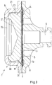
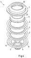
- Fig. 3 and 4 show a second embodiment of a capsule 1 according to the invention.
- the diaphragms 2 also have the function of a valve element to open or close the valve seat 3. Consequently, in contrast to the first embodiment no dedicated valve element is used.
- a spring is also omitted.
- This embodiment is simpler in construction compared to the first embodiment and is for example advantageous if the fluid that has to be controlled is usually not entering the valve at a pressure below atmospheric pressure. Consequently, the fluid pressure itself may depending on the presetting force be sufficient to keep the valve open.
- a further difference to the first embodiment is that in the second embodiment three diaphragms 2 are used.
- the second embodiment comprises four capsule inlets 5 in contrast to the first embodiment. Apart from the named differences the remaining features of the second embodiment correspond to those of the first embodiment.
- Fig. 5 and 6 show a third embodiment of a capsule 1 according to the invention. Again corresponding features to the first two embodiments are denoted with the same reference signs.
- the third embodiment is identical to the first embodiment apart from two differences. First of all there is only one capsule inlet 5 instead of two capsule inlets. Furthermore, three diaphragms 2 are used instead of two diaphragms.
- a spring 14 in the shape of a wave spring is shown in Fig. 7 , as used in the first and third embodiments.
- Fig. 8 to 11 show embodiments of the valve according to the invention in which the valve is a pilot valve to be used together with a main valve.
- the pilot valve can in these embodiments control the opening and closing behavior of the main valve.
- Fig. 8 shows a fourth embodiment according to the invention of a valve 10.
- the valve 10 comprises a capsule 1 according to any of the above embodiments.
- the valve 10 comprises a valve housing 15 in which the capsule 1 is arranged.
- the valve housing 15 here comprises a first housing part 25 and a second housing part 26 between which the capsule 1 is fixed.
- the valve 10 comprises valve inlets 19 which are connected to the capsule inlets 5 of the capsule 1.
- An outlet 20 is connected to the capsule outlet 6 of the capsule 1.
- the valve 10 furthermore comprises a presetting mechanism 16.
- the presetting mechanism 16 in this embodiment comprises a spring mechanism 17.
- the spring mechanism 17 comprises a thrust head 27 to engage the converging bore 21 of the thrust pad 9.
- the spring mechanism 17 allows to adjust the minimum pressure differential necessary to open the valve.
- the presetting force of the spring mechanism 17 can be adjusted by a presetting spindle 29.
- the presetting spindle 29 is here covered by a protective cap 28.
- the pressure in the pressure chamber 23 of the capsule 1 will usually be given by atmospheric pressure.
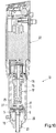
- Fig. 9 shows a fifth embodiment according to the invention.
- This embodiment is mostly identical to the fourth embodiment except for an additional presetting means.
- the presetting mechanism 16 here in addition to a spring mechanism 17 with a presetting handle 29 also comprises a pressure port 18.
- the pressure port 18 allows to change the pressure in the pressure chamber 23 on the side of the diaphragm 2 opposite to the valve seat. Consequently, by increasing the pressure on the side of the diaphragm opposite to the valve seat the minimum pressure necessary on the side of the capsule inlet 5 to open the valve is increased.
- This embodiment is more flexible with respect to the fluids and pressures the valve 10 can be used with.
- Fig. 10 shows a sixth embodiment according to the invention. Again corresponding features to the previous embodiments are denoted with the same reference signs.
- the sixth embodiment is similar to the fourth embodiment in that the presetting mechanism 16 comprises a spring mechanism 17.
- the presetting mechanism 17 here is controlled by a stepper motor 22.
- the stepper motor 22 can for example be controlled by an external control unit which allows to control the opening pressure differential of the valve during operation of the valve 10.
- Fig. 11 shows a seventh embodiment according to the invention.
- the capsule 1 serves to indirectly control the opening behavior of the pilot valve 10.
- the valve 10 in this embodiment comprises a pilot valve element 34 external to the capsule 1.
- the pilot valve element 34 is actuatable by a displacement of the valve element 4 in the capsule 1.
- the valve element 4 and the pilot valve element 34 are indirectly connected by a pin 33.
- One axial end of the pin 33 abuts the valve element 4.
- the opposite end of the pin 33 is connected to the pilot valve element 34.
- the pilot valve element 34 is axially displaceable towards or away from a pilot valve seat 38 external to the capsule 1.
- the capsule 1 is connected to a pressure port 37 which provides a reference pressure used to control the opening or closing of the valve 10.
- the presetting mechanism 16 here similarly to the embodiments according to Fig. 8 and 9 comprises a spring mechanism 17.
- the main flow path through the valve 10 does not lead through the capsule 1 in this embodiment.
- the capsule 1 serves to actuate and preset the valve 10 together with the presetting mechanism 16.
- the valve 10 according to Fig. 11 is to be used together with a main valve with a housing to which the valve inlet 19 and the valve outlet 20 connect.
- Fig. 12 shows an eighth embodiment according to the invention.
- the valve 10 here is a main valve, or in other words the capsule 1 is not part of a pilot valve.
- the valve 10 here is a regulating valve controlling the flow through the valve via the pressure difference over the diaphragm.
- the valve housing 15 here comprises an additional housing part 39 which extends the valve inlet 19 and the valve outlet 20.
Landscapes
- Engineering & Computer Science (AREA)
- General Engineering & Computer Science (AREA)
- Mechanical Engineering (AREA)
- Fluid-Driven Valves (AREA)
- Safety Valves (AREA)
Abstract
Description
- The invention relates to a capsule for a valve as well as to a valve.
- In many kinds of valves diaphragms are used to separate pressure chambers to allow a partial or complete pressure control of the valve. For example, pilot valves are often at least partially pressure regulated and comprise two or more pressure chambers that are separated by a diaphragm. The diaphragm can either comprise or cooperate with a valve element to close or open a valve seat depending on the pressure difference between the pressure chambers.
- The diaphragm is usually fixed between parts of the valve housing when assembling the valve.
- However, it can be difficult to achieve tight tolerances in construction and consequently a precise opening behavior this way. Furthermore, the known valves comprising diaphragms usually cannot be serviced and need to be replaced in case of a malfunction.
- The task underlying the present invention is therefore to provide valve parts for a valve as well as a valve that can be easier assembled and disassembled and that allows to achieve tighter tolerances in construction.
- According to the present invention the above task is solved by a capsule for a valve that comprises at least one diaphragm, a valve seat, a capsule inlet and a capsule outlet.
- According to the present invention the parts which usually require the tightest tolerances are therefore arranged in a capsule. Consequently, this capsule can be preassembled with a manufacture method that allows tighter tolerances. Afterwards the capsule can be inserted into a valve by manual assembly. Similarly, if a valve comprising such a capsule needs to be serviced, the complete capsule can be replaced which speeds up the servicing and reduces the risk of an incorrect or imprecise reassembly of the valve. Consequently, both the maintenance interval as well as the overall lifetime of a valve comprising a capsule according to the invention is increased. The capsule may comprise one, two, three or more diaphragms. Preferably, the diaphragms are stacked on top of each other. This has the advantage that a standard diaphragm can be used and the number of the standard diaphragms can be chosen according to the required strength and flexibility. The capsule can comprise one, two, three, four or more capsule inlets. Preferably, the valve seat is openable to permit a fluid flow from the capsule inlet to the capsule outlet, wherein the valve seat is closable to stop a fluid flow from the capsule inlet to the capsule outlet. In this case the capsule provides the main fluid path through the valve. The capsule may either be used for a pilot valve or may be part of a main valve. The capsule may, however, alternatively be used to control the position of a pilot valve element to a valve seat that are external to the capsule.
- In a preferred embodiment the capsule comprises a capsule top and a capsule bottom, wherein at least one diaphragm is fixed at a radially outer end of the diaphragm between the capsule top and the capsule bottom. Preferably, two, three or more diaphragms are stacked on top of each other and fixed collectively at a radial outer end of the diaphragms between the capsule top and the capsule bottom. The use of a capsule top and a capsule bottom keeps the number of parts of the capsule small, while allowing a simple assembly of the capsule. Preferably, both the capsule inlet as well as the capsule outlet are arranged in either the capsule top or the capsule bottom. This way it is ensured that both the capsule inlet and the capsule outlet are connected to the same pressure chamber.
- It is preferred if at least one diaphragm also has the function of a valve element to open or close the valve seat. In this embodiment one may dispense with the use of a dedicated valve element. This on the one hand allows for a more compact construction of the capsule and on the other hand allows to dispense with a dedicated valve element as well as a spring element for loading the valve element.
- Alternatively, a valve element is arranged in the capsule in addition to the at least one diaphragm. Preferably, the valve element is arranged to open or close the valve seat. In this case a dedicated valve element is arranged in the capsule in addition to the at least one diaphragm. The valve element is preferably loaded by a spring element. However, the valve element can also serve to actuate a valve element external to the capsule, for example, by engaging a pin connected to the valve element.
- It is preferred if the capsule comprises at least one thrust pad arranged at a first face of the at least one diaphragm opposite to a second face of the at least one diaphragm facing the valve seat. Such a thrust pad can for example allow a presetting mechanism of the valve to engage the capsule. Such a presetting mechanism for example allows to choose the minimum pressure difference between the two sides of the diaphragm necessary to open the valve. In case several stacked diaphragms are used the first face and the second face denote the surfaces of the outermost diaphragms.
- It is preferred if the capsule comprises an aperture facing the thrust pad. Such an aperture allows a presetting mechanism of the valve to engage the thrust pad. At the same time such an aperture can allow a communication of pressure from one of the pressure chambers of the capsule to the valve. Depending on the valve this can either be the atmospheric pressure or a controllable presetting pressure of the valve.
- It is preferred if the thrust pad comprises a converging bore on a side facing the aperture. This for example allows to center a presetting mechanism engaging the thrust pad. The assembly of the valve comprising a capsule according to the invention is thus simplified.
- It is furthermore preferred if a spring is arranged in the capsule to load the valve element. Preferably, the spring is a wave spring. The spring is preferably arranged on the side of the at least one diaphragm facing the capsule inlet and/or the capsule outlet. The use of a spring to load to valve element is in particular preferable if the valve is used in a refrigeration system in which the fluid pressure can be lower than the atmospheric pressure. In this case the additional spring force ensures that the valve can be kept open even if the pressure on the side of the diaphragm facing the capsule inlet is lower than on the side of the diaphragm opposite the capsule inlet. An example of a refrigeration system operating with fluid pressures below atmospheric pressure are ammonia refrigeration systems.
- The above task is also solved by a valve comprising a valve housing, characterized in that a capsule according to any of the above embodiments is arranged in the valve housing. Preferably, the capsule is fixed between two parts of the valve housing of the valve.
- It is preferred if the valve comprises a presetting mechanism. Such a presetting mechanism allows to choose the pressure differential between the pressure chambers on both sides of the at least one diaphragm that is necessary to keep the valve open. Such a presetting mechanism may for example engage the thrust pad mechanically or allow to change the pressure on one side of the at least one diaphragm.
- Preferably, the presetting mechanism comprises a spring mechanism with an adjustable presetting force. The spring mechanism may to this end engage the thrust pad and in particular the converging bore of the thrust pad. The spring mechanism may be manually adjustable or may be adjustable via an electric actuator like a stepper motor.
- In a further preferred embodiment the presetting mechanism comprises a pressure port to adjust the pressure on the side of the diaphragm opposite to the valve seat. This way the minimum pressure at the capsule inlet side of the diaphragm necessary to open the valve may be adjusted. This provides an override option to open or close the valve if necessary. If no pressure port is used the pressure on the side of the diaphragm opposite to the capsule inlet is preferably atmospheric pressure.
- It is furthermore preferred if the presetting mechanism comprises a stepper motor to adjust the presetting force of the spring mechanism. This has the advantage that the minimum pressure difference between the two sides of the diaphragm necessary to open the valve can be adjusted and controlled externally for example by a control unit connected to the stepper motor.
- It is furthermore preferred if the valve housing comprises a valve inlet and a valve outlet, wherein the valve inlet is connected to the capsule inlet and the valve outlet is connected to the capsule outlet. In this case, the main fluid path through the valve leads through the capsule.
- Preferably, the valve is a pilot valve that comprises a valve element external to the capsule, wherein the pilot valve element is actuatable by a displacement of the valve element in the capsule. The valve element and the pilot valve element preferably are indirectly connected by a pin. The valve element can be fixed to one end of the pin. The valve element in the capsule can abut the opposite end of the pin. In this embodiment the main fluid path through the pilot valve may not lead through the capsule. The capsule may in this case be used to control the opening and closing of the valve by actuating the valve element towards a valve seat external to the capsule.
- It is preferred if a first face of the at least one diaphragm is loaded by a presetting pressure while a second face of the at least one diaphragm is loaded by a pressure from the capsule inlet. The presetting pressure may for example be atmospheric pressure or an adjustable pressure provided by a pressure port of the presetting mechanism.
- Preferred embodiments of the invention are now described with reference to the figures, wherein:
- Fig. 1
- shows a cut view of a first embodiment of a capsule according to the invention,
- Fig. 2
- shows an exploded view of a capsule according to the first embodiment,
- Fig. 3
- shows a cut view of a second embodiment of a capsule according to the invention,
- Fig. 4
- shows an exploded view of a capsule according to the second embodiment,
- Fig. 5
- shows a cut view of a third embodiment of a capsule according to the invention
- Fig. 6
- shows an exploded view of a capsule according to the third embodiment,
- Fig. 7
- shows a spring as used in a capsule according to the first and third embodiments,
- Fig. 8
- shows a fourth embodiment according to the invention,
- Fig. 9
- shows a fifth embodiment according to the invention,
- Fig. 10
- shows a sixth embodiment according to the invention, and
- Fig. 11
- shows a seventh embodiment according to the invention,
- Fig. 12
- shows an eighth embodiment according to the invention.
-
Fig. 1 and2 show a first embodiment of acapsule 1 according to the invention. Thecapsule 1 comprises at least onediaphragm 2, in this case twodiaphragms 2. Thediaphragms 2 are fixed to thecapsule 1 at circumferential ends of thediaphragms 2. Here thediaphragms 2 are fixed between acapsule top 7 and acapsule bottom 8 at the outer ends of thediaphragms 2. Thecapsule top 7 and thecapsule bottom 8 can be welded together by laser welding. The rest of thediaphragms 2 and in particular a central portion of thediaphragms 2 can move more or less freely inside thecapsule 1. Thecapsule 1 furthermore comprises avalve seat 3 as well as avalve element 4. Thevalve element 4 is loaded by aspring 14. Thespring 14 rests against thecapsule bottom 8 at the end of the spring opposite to thevalve element 4. Thespring 14 here is a wave spring that is shown in more detail inFig. 7 . - The
capsule 1 in this embodiment comprises twocapsule inlets 5 as well as onecapsule outlet 6. - The
thrust pad 9 comprises a convergingbore 21 that is aligned with anaperture 13 of thecapsule top 7. This way a presetting mechanism of the valve can engage thethrust pad 9. Thecapsule 1 comprises twopressure chambers diaphragms 2. In the shown cut view ofFig. 1 thediaphragms 2 are in a neutral position, which they will usually not assume during operation of the valve because the pressure difference between thepressure chambers valve element 4 will be lifted from the valve seat to open a fluid flow from thecapsule inlets 5 to thecapsule outlet 6 when the force of thespring 14 is larger than the differential pressure force acting on thevalve element 4 through thediaphragm 2 as well as an optional presetting force that can act on thethrust pad 9 via a presetting mechanism that will later be described in more detail. In particular in ammonia refrigeration systems the fluid pressure at the inlet side of thediaphragm 2 can be well below atmospheric pressure, so thespring 14 may have to overcome a differential pressure force. - The
thrust pad 9 is arranged in thepressure chamber 23. Thethrust pad 9 is arranged neighboring afirst face 11 of thediaphragms 2 opposite to thevalve seat 3. Thevalve element 4 on the other hand is arranged neighboring asecond face 12 of thediaphragms 2 in thepressure chamber 24. - The
thrust pad 9 has a cylinder like shape. A roundedcircumferential corner 30 of thethrust pad 9 between a side facing theaperture 13 and a radiallyouter surface 31 has a larger radius of curvature than a neighboring corner of thecapsule top 7. This way one may avoid thethrust pad 9 sticking to thecapsule top 7 in case thethrust pad 9 tilts during operation. The radiallyouter surface 31 may furthermore have a wave-like cross section to further avoid a sticking of thethrust pad 9 to thecapsule top 7. - The
thrust pad 9 comprises acircular recess 32 on the side facing thediaphragm 2. Thecircular recess 32 is preferably arranged at a radially outer end of the side facing thediaphragm 2. Thecircular recess 32 increases the lifetime of thecapsule 1 and in particular of thediaphragm 2 because it reduces the wear of thediaphragm 2. -
Fig. 3 and4 show a second embodiment of acapsule 1 according to the invention. Corresponding elements are denoted with the same reference signs as in the previous embodiment. In this embodiment thediaphragms 2 also have the function of a valve element to open or close thevalve seat 3. Consequently, in contrast to the first embodiment no dedicated valve element is used. A spring is also omitted. This embodiment is simpler in construction compared to the first embodiment and is for example advantageous if the fluid that has to be controlled is usually not entering the valve at a pressure below atmospheric pressure. Consequently, the fluid pressure itself may depending on the presetting force be sufficient to keep the valve open. A further difference to the first embodiment is that in the second embodiment threediaphragms 2 are used. Furthermore, the second embodiment comprises fourcapsule inlets 5 in contrast to the first embodiment. Apart from the named differences the remaining features of the second embodiment correspond to those of the first embodiment. -
Fig. 5 and6 show a third embodiment of acapsule 1 according to the invention. Again corresponding features to the first two embodiments are denoted with the same reference signs. The third embodiment is identical to the first embodiment apart from two differences. First of all there is only onecapsule inlet 5 instead of two capsule inlets. Furthermore, threediaphragms 2 are used instead of two diaphragms. - A
spring 14 in the shape of a wave spring is shown inFig. 7 , as used in the first and third embodiments. -
Fig. 8 to 11 show embodiments of the valve according to the invention in which the valve is a pilot valve to be used together with a main valve. The pilot valve can in these embodiments control the opening and closing behavior of the main valve. -
Fig. 8 shows a fourth embodiment according to the invention of avalve 10. Thevalve 10 comprises acapsule 1 according to any of the above embodiments. Thevalve 10 comprises avalve housing 15 in which thecapsule 1 is arranged. Thevalve housing 15 here comprises afirst housing part 25 and asecond housing part 26 between which thecapsule 1 is fixed. Thevalve 10 comprisesvalve inlets 19 which are connected to thecapsule inlets 5 of thecapsule 1. Anoutlet 20 is connected to thecapsule outlet 6 of thecapsule 1. - The
valve 10 furthermore comprises apresetting mechanism 16. Thepresetting mechanism 16 in this embodiment comprises aspring mechanism 17. Thespring mechanism 17 comprises athrust head 27 to engage the converging bore 21 of thethrust pad 9. Thespring mechanism 17 allows to adjust the minimum pressure differential necessary to open the valve. The presetting force of thespring mechanism 17 can be adjusted by apresetting spindle 29. The presettingspindle 29 is here covered by aprotective cap 28. - In this embodiment the pressure in the
pressure chamber 23 of thecapsule 1 will usually be given by atmospheric pressure. -
Fig. 9 shows a fifth embodiment according to the invention. Corresponding features to the previous embodiments are denoted with the same reference signs. This embodiment is mostly identical to the fourth embodiment except for an additional presetting means. Thepresetting mechanism 16 here in addition to aspring mechanism 17 with apresetting handle 29 also comprises apressure port 18. Thepressure port 18 allows to change the pressure in thepressure chamber 23 on the side of thediaphragm 2 opposite to the valve seat. Consequently, by increasing the pressure on the side of the diaphragm opposite to the valve seat the minimum pressure necessary on the side of thecapsule inlet 5 to open the valve is increased. This embodiment is more flexible with respect to the fluids and pressures thevalve 10 can be used with. -
Fig. 10 shows a sixth embodiment according to the invention. Again corresponding features to the previous embodiments are denoted with the same reference signs. The sixth embodiment is similar to the fourth embodiment in that thepresetting mechanism 16 comprises aspring mechanism 17. However, thepresetting mechanism 17 here is controlled by astepper motor 22. Thestepper motor 22 can for example be controlled by an external control unit which allows to control the opening pressure differential of the valve during operation of thevalve 10. -
Fig. 11 shows a seventh embodiment according to the invention. In this embodiment of thevalve 10 thecapsule 1 serves to indirectly control the opening behavior of thepilot valve 10. Thevalve 10 in this embodiment comprises apilot valve element 34 external to thecapsule 1. Thepilot valve element 34 is actuatable by a displacement of thevalve element 4 in thecapsule 1. Thevalve element 4 and thepilot valve element 34 are indirectly connected by apin 33. One axial end of thepin 33 abuts thevalve element 4. The opposite end of thepin 33 is connected to thepilot valve element 34. Thepilot valve element 34 is axially displaceable towards or away from apilot valve seat 38 external to thecapsule 1. Thecapsule 1 is connected to apressure port 37 which provides a reference pressure used to control the opening or closing of thevalve 10. Thepresetting mechanism 16 here similarly to the embodiments according toFig. 8 and9 comprises aspring mechanism 17. - The main flow path through the
valve 10 does not lead through thecapsule 1 in this embodiment. Thecapsule 1 serves to actuate and preset thevalve 10 together with thepresetting mechanism 16. Thevalve 10 according toFig. 11 is to be used together with a main valve with a housing to which thevalve inlet 19 and thevalve outlet 20 connect. -
Fig. 12 shows an eighth embodiment according to the invention. Contrary to the previous embodiments thevalve 10 here is a main valve, or in other words thecapsule 1 is not part of a pilot valve. Thevalve 10 here is a regulating valve controlling the flow through the valve via the pressure difference over the diaphragm. When comparing to the embodiment according toFig. 8 thevalve housing 15 here comprises anadditional housing part 39 which extends thevalve inlet 19 and thevalve outlet 20.
Claims (15)
- A capsule (1) for a valve characterized in that the capsule (1) comprises at least one diaphragm (2), a valve seat (3), a capsule inlet (5) and a capsule outlet (6).
- The capsule according to claim 1 characterized in that the capsule (1) comprises a capsule top (7) and a capsule bottom (8), wherein at least one diaphragm (2) is fixed at a radially outer end of the diaphragm (2) between the capsule top (7) and the capsule bottom (8).
- The capsule according to claim 1 or 2, characterized in that the at least one diaphragm (2) also has the function of a valve element to open or close the valve seat (3).
- The capsule according to claim 1 or 2, characterized in that a valve element (4) is arranged in the capsule (1) in addition to the at least one diaphragm (2) to open or close the valve seat (3).
- The capsule according to any of claims 1 to 4, characterized in that the capsule (1) comprises at least one thrust pad (9) arranged at a first face (11) of the at least one diaphragm (2) opposite to a second face (12) of the at least one diaphragm (2) facing the valve seat (3).
- The capsule according to claim 5, characterized in that the capsule (1) comprises an aperture (13) facing the thrust pad (9).
- The capsule according to claim 6, characterized in that the thrust pad (9) comprises a converging bore (21) on a side facing the aperture (13).
- The capsule according to any of claims 4 to 7, characterized in that a spring (14) is arranged in the capsule (1) to load the valve element (4).
- A valve (10) comprising a valve housing (15), characterized in that a capsule (1) according to any of claims 1 to 8 is arranged in the valve housing (15).
- The valve according to claim 9, characterized in that the valve (10) comprises a presetting mechanism (16).
- The valve according to claim 10, characterized in that the presetting mechanism (16) comprises a spring mechanism (17) with an adjustable presetting force.
- The valve according to claim 10 or 11, characterized in that the presetting mechanism (16) comprises a pressure port (18) to adjust pressure on the side of the diaphragm (2) opposite to the valve seat (3).
- The valve according to claim 11 or 12, characterized in that the presetting mechanism (16) comprises a stepper motor (22) to adjust the presetting force of the spring mechanism (17).
- The valve according to any of claims 9 to 13, characterized in that the valve (10) is a pilot valve that comprises a pilot valve element (34) external to the capsule (1), wherein the pilot valve element (34) is actuatable by a displacement of the valve element (4) in the capsule (1).
- The valve (10) according to any of claims 9 to 14, characterized in that the first face (11) of the at least one diaphragm (2) is loaded by a presetting pressure while the second face (12) of the at least one diaphragm (2) is loaded by a pressure from the capsule inlet(s).
Priority Applications (5)
| Application Number | Priority Date | Filing Date | Title |
|---|---|---|---|
| EP16150039.2A EP3187758B1 (en) | 2016-01-04 | 2016-01-04 | Capsule for a valve and valve |
| ES16150039T ES2733448T3 (en) | 2016-01-04 | 2016-01-04 | Capsule for a valve and valve |
| CN201780005717.7A CN108431474B (en) | 2016-01-04 | 2017-01-03 | Capsule for a valve and valve |
| PCT/EP2017/050093 WO2017118637A1 (en) | 2016-01-04 | 2017-01-03 | Capsule for a valve and valve |
| US16/065,976 US11555550B2 (en) | 2016-01-04 | 2017-01-03 | Capsule for a valve and valve |
Applications Claiming Priority (1)
| Application Number | Priority Date | Filing Date | Title |
|---|---|---|---|
| EP16150039.2A EP3187758B1 (en) | 2016-01-04 | 2016-01-04 | Capsule for a valve and valve |
Publications (2)
| Publication Number | Publication Date |
|---|---|
| EP3187758A1 true EP3187758A1 (en) | 2017-07-05 |
| EP3187758B1 EP3187758B1 (en) | 2019-04-03 |
Family
ID=55069792
Family Applications (1)
| Application Number | Title | Priority Date | Filing Date |
|---|---|---|---|
| EP16150039.2A Active EP3187758B1 (en) | 2016-01-04 | 2016-01-04 | Capsule for a valve and valve |
Country Status (5)
| Country | Link |
|---|---|
| US (1) | US11555550B2 (en) |
| EP (1) | EP3187758B1 (en) |
| CN (1) | CN108431474B (en) |
| ES (1) | ES2733448T3 (en) |
| WO (1) | WO2017118637A1 (en) |
Cited By (1)
| Publication number | Priority date | Publication date | Assignee | Title |
|---|---|---|---|---|
| US11879676B2 (en) | 2021-07-30 | 2024-01-23 | Danfoss A/S | Thermal expansion valve for a heat exchanger and heat exchanger with a thermal expansion valve |
Families Citing this family (2)
| Publication number | Priority date | Publication date | Assignee | Title |
|---|---|---|---|---|
| EP4332417A1 (en) * | 2020-04-30 | 2024-03-06 | Emerson Automation Solutions Final Control US LP | Systems and methods for determining failure in a back pressure balanced relief valve |
| USD1073018S1 (en) * | 2021-08-02 | 2025-04-29 | Stego Holding Gmbh | Pressure reducer |
Citations (6)
| Publication number | Priority date | Publication date | Assignee | Title |
|---|---|---|---|---|
| US4265270A (en) * | 1979-03-08 | 1981-05-05 | Tel-Thermco Engineering Co., Ltd. | Remote-controlled pressure regulator |
| DE3831474A1 (en) * | 1988-09-16 | 1990-04-05 | Gestra Ag | Thermally controlled valve |
| US5076320A (en) * | 1990-10-19 | 1991-12-31 | Siemens Automotive L.P. | Fuel rail mounted fuel pressure regulator |
| US20030042459A1 (en) * | 2001-08-29 | 2003-03-06 | Gregoire Roger J. | Unitary diaphragm and seat assembly |
| US20090235901A1 (en) * | 2006-04-12 | 2009-09-24 | Toyota Jidosha Kabushiki Kaisha | Fuel Supply System For An Internal Combustion Engine |
| US20140319403A1 (en) * | 2011-12-05 | 2014-10-30 | Fujikin Incorporated | Diaphragm valve and seat holder unit for diaphragm valve |
Family Cites Families (54)
| Publication number | Priority date | Publication date | Assignee | Title |
|---|---|---|---|---|
| US237624A (en) * | 1881-02-08 | Biohaed h | ||
| US479234A (en) * | 1892-07-19 | Fluid-pressure regulator | ||
| US1626673A (en) * | 1924-10-17 | 1927-05-03 | Westinghouse Air Brake Co | Flexible diaphragm device |
| US2189750A (en) * | 1938-12-23 | 1940-02-13 | Nat Meter Company | By-pass compensator for meters |
| US2413380A (en) * | 1944-08-31 | 1946-12-31 | Westinghouse Air Brake Co | Fluid pressure motor |
| GB677632A (en) * | 1948-03-10 | 1952-08-20 | Refrigerator Components Ltd | Improvements in or relating to expansion valves for use in refrigerators |
| US2720887A (en) * | 1952-11-21 | 1955-10-18 | New York Air Brake Co | Pressure reducing valve with over pressure relief |
| US3321173A (en) * | 1964-02-27 | 1967-05-23 | United Aircraft Corp | Low flow valve |
| US3250083A (en) | 1964-06-10 | 1966-05-10 | Controls Co Of America | Frost sensing device |
| US3405730A (en) * | 1965-12-20 | 1968-10-15 | Cash A W Co | Pressure relief valve having tubular plug |
| US3756473A (en) | 1971-12-20 | 1973-09-04 | Eaton Corp | Dispenser assembly |
| IT1105856B (en) * | 1978-02-07 | 1985-11-04 | Weber Edoardo Spa Fabbrica | PRESSURE REGULATOR FOR INJECTION SYSTEMS OF INTERNAL COMBUSTION ENGINES |
| US4357748A (en) * | 1978-08-23 | 1982-11-09 | Robertshaw Controls Company | Fluid flow sensing switch device method of making the same |
| US4237924A (en) * | 1978-12-05 | 1980-12-09 | Schmelzer Corporation | Fuel pressure regulator |
| US4336824A (en) * | 1980-05-29 | 1982-06-29 | United Aircraft Products, Inc. | Cartridge valve |
| US4373545A (en) * | 1981-01-26 | 1983-02-15 | Cherry-Burrell Corporation | Double block and vent valve |
| US4653528A (en) * | 1986-02-18 | 1987-03-31 | General Motors Corporation | Multi-adaptive fuel pressure regulator |
| US4741360A (en) * | 1987-09-14 | 1988-05-03 | Tom Mcguane Industries, Inc. | Fuel pressure regulator |
| US4936342A (en) * | 1988-01-27 | 1990-06-26 | Mitsuba Electric Manufacturing Co., Ltd. | Fuel pressure control valve device |
| IT1223939B (en) * | 1988-11-25 | 1990-09-29 | Weber Srl | PRESSURE REGULATOR FOR THE FUEL CIRCUIT OF A FUEL SYSTEM OF AN INTERNAL COMBUSTION ENGINE |
| JP2540795Y2 (en) * | 1991-03-25 | 1997-07-09 | 株式会社ミツバ | Fuel pressure control valve |
| US5213126A (en) * | 1991-05-15 | 1993-05-25 | Mitsuba Electric Manufacturing Co., Ltd. | Pressure control valve and method of manufacturing same |
| DE4212968C2 (en) * | 1992-04-18 | 1998-07-02 | Mann & Hummel Filter | Pressure control valve for the crankcase ventilation of an internal combustion engine |
| US5275201A (en) * | 1992-07-23 | 1994-01-04 | Tri-Clover, Inc. | Manifold valve assembly with removable valve seat |
| DE19522042A1 (en) * | 1995-06-17 | 1996-12-19 | Bosch Gmbh Robert | Pressure control valve for IC engine fuel supply |
| IT1287785B1 (en) * | 1996-05-16 | 1998-08-18 | Htm Sport Spa | PRESSURE REDUCER, FOR THE FIRST STAGE OF REDUCTION OF TWO-STAGE UNDERWATER SCUBA RESPIRATORS. |
| US6003499A (en) * | 1998-01-07 | 1999-12-21 | Stant Manufacturing Inc. | Tank vent control apparatus |
| US6360963B2 (en) * | 2000-01-12 | 2002-03-26 | Woodward Governor Company | Gaseous fuel injector having high heat tolerance |
| DE10008227A1 (en) * | 2000-02-22 | 2001-08-23 | Bosch Gmbh Robert | Device with a membrane arrangement |
| US6318405B1 (en) * | 2000-03-08 | 2001-11-20 | Mahle-Parr Filter Systems, Inc. | Fuel pressure regulator with fluidic assist |
| DE20016214U1 (en) * | 2000-09-18 | 2002-02-07 | Ing. Walter Hengst GmbH & Co. KG, 48147 Münster | Throttle valve for automatic regulation of the pressure in the crankcase of an internal combustion engine |
| US6422265B1 (en) * | 2000-12-15 | 2002-07-23 | Delphi Technologies, Inc. | Valve seat for fuel pressure regulator |
| DE20211329U1 (en) * | 2002-07-26 | 2003-12-04 | Hengst Gmbh & Co.Kg | Oil separator for separating oil from the crankcase ventilation gas of an internal combustion engine |
| CN100410601C (en) | 2002-12-05 | 2008-08-13 | 周纪昌 | Air conditioner pressure regulating unloading valve |
| US6834673B2 (en) * | 2002-12-20 | 2004-12-28 | Siemens Vdo Automotive Corporation | Pump module with pressure regulator |
| US20050055256A1 (en) * | 2003-09-04 | 2005-03-10 | Kevin Scott | Method and system for filling vacancies |
| ATE394726T1 (en) * | 2004-03-12 | 2008-05-15 | Hengst Gmbh & Co Kg | PNEUMATIC PRESSURE REGULATOR VALVE |
| US20050229976A1 (en) * | 2004-04-16 | 2005-10-20 | Yao-Hwan Kao | Adjustable rinse flow in semiconductor processing |
| EP1809959B1 (en) * | 2004-10-21 | 2008-06-25 | Danfoss A/S | Valve for use in a refrigeration system |
| DE102006024820A1 (en) * | 2006-05-29 | 2007-12-13 | Mahle International Gmbh | Device for separating a gas-liquid mixture, in particular in the venting of a crankcase of an internal combustion engine |
| US8459297B2 (en) * | 2009-07-02 | 2013-06-11 | Tescom Corporation | Balanced valve cartridge |
| US20110174398A1 (en) * | 2009-07-02 | 2011-07-21 | Jason David Clifford | Valve apparatus to prevent contamination of fluid in a fluid regulator |
| US9874883B2 (en) * | 2009-07-02 | 2018-01-23 | Tescom Corporation | Diaphragm interface apparatus to improve a cycle life of a diaphragm |
| US20110073071A1 (en) | 2009-09-30 | 2011-03-31 | Woodward Governor Company | Internally Nested Variable-Area Fuel Nozzle |
| US9032991B2 (en) * | 2011-05-03 | 2015-05-19 | Emerson Electric Co. | Field adjustable gas valve and method of control |
| CN202300937U (en) | 2011-11-04 | 2012-07-04 | 蚌埠市伟瑞工贸有限公司 | Air inlet and exhaust combination valve of natural gas compressor |
| ITGE20120026A1 (en) * | 2012-03-05 | 2013-09-06 | Mares Spa | SHUTTER OF A PRESSURE REDUCTION VALVE OF A PRESSURE ADJUSTMENT DEVICE AND PRESSURE ADJUSTMENT DEVICE PROVIDED WITH SUCH A SHUTTER |
| US9303777B2 (en) * | 2012-04-09 | 2016-04-05 | II Lawrence L. Frahm | Pressure limiting valve and alternative method for testing a backflow preventer using the same |
| DK2855989T3 (en) * | 2012-06-01 | 2016-11-14 | Avk Holding As | Hydraulic control valve device and control system for water supply networks |
| DE102012221695A1 (en) | 2012-11-28 | 2014-05-28 | Robert Bosch Gmbh | Valve i.e. suction valve for exhaust gas after treatment system for introducing service or auxiliary substance into exhaust gas tract of internal combustion engine, has valve membrane clamped between valve cover and plate under tension |
| JP6335926B2 (en) * | 2013-02-01 | 2018-05-30 | スウエイジロク・カンパニー | Diaphragm valve with welded diaphragm valve seat carrier |
| US9441745B2 (en) * | 2014-03-03 | 2016-09-13 | Emerson Process Management Regulator Technologies, Inc. | Apparatus to interface with a corrugated diaphragm |
| CN205207814U (en) | 2015-10-30 | 2016-05-04 | 重庆市界石燃气设备有限公司 | Balanced voltage regulator |
| DE102017010018A1 (en) * | 2016-11-02 | 2018-05-03 | Mann + Hummel Gmbh | Unit for regulating or controlling a fluid pressure |
-
2016
- 2016-01-04 EP EP16150039.2A patent/EP3187758B1/en active Active
- 2016-01-04 ES ES16150039T patent/ES2733448T3/en active Active
-
2017
- 2017-01-03 WO PCT/EP2017/050093 patent/WO2017118637A1/en not_active Ceased
- 2017-01-03 CN CN201780005717.7A patent/CN108431474B/en active Active
- 2017-01-03 US US16/065,976 patent/US11555550B2/en active Active
Patent Citations (6)
| Publication number | Priority date | Publication date | Assignee | Title |
|---|---|---|---|---|
| US4265270A (en) * | 1979-03-08 | 1981-05-05 | Tel-Thermco Engineering Co., Ltd. | Remote-controlled pressure regulator |
| DE3831474A1 (en) * | 1988-09-16 | 1990-04-05 | Gestra Ag | Thermally controlled valve |
| US5076320A (en) * | 1990-10-19 | 1991-12-31 | Siemens Automotive L.P. | Fuel rail mounted fuel pressure regulator |
| US20030042459A1 (en) * | 2001-08-29 | 2003-03-06 | Gregoire Roger J. | Unitary diaphragm and seat assembly |
| US20090235901A1 (en) * | 2006-04-12 | 2009-09-24 | Toyota Jidosha Kabushiki Kaisha | Fuel Supply System For An Internal Combustion Engine |
| US20140319403A1 (en) * | 2011-12-05 | 2014-10-30 | Fujikin Incorporated | Diaphragm valve and seat holder unit for diaphragm valve |
Cited By (1)
| Publication number | Priority date | Publication date | Assignee | Title |
|---|---|---|---|---|
| US11879676B2 (en) | 2021-07-30 | 2024-01-23 | Danfoss A/S | Thermal expansion valve for a heat exchanger and heat exchanger with a thermal expansion valve |
Also Published As
| Publication number | Publication date |
|---|---|
| ES2733448T3 (en) | 2019-11-29 |
| CN108431474B (en) | 2020-02-04 |
| WO2017118637A1 (en) | 2017-07-13 |
| US11555550B2 (en) | 2023-01-17 |
| CN108431474A (en) | 2018-08-21 |
| EP3187758B1 (en) | 2019-04-03 |
| US20190003607A1 (en) | 2019-01-03 |
Similar Documents
| Publication | Publication Date | Title |
|---|---|---|
| KR101557516B1 (en) | Hydraulic control valve having integrated check valve | |
| CN111828723B (en) | Proportional hydraulic valve | |
| EP2818779B1 (en) | Solenoid valve | |
| EP3129660B1 (en) | Servo valve | |
| EP3147594B1 (en) | Valve for a refrigeration system | |
| US11555550B2 (en) | Capsule for a valve and valve | |
| JP5966094B2 (en) | Solenoid valve | |
| CN115306669B (en) | Capacity control valve | |
| US11047400B2 (en) | Fluid pressure control device | |
| EP2160666B1 (en) | Pressure regulator valve | |
| US20180195627A1 (en) | Combination valve and bidirectional flow control valve using the same | |
| CN101080592B (en) | Hydraulic control valve with integrated dual actuators | |
| US4821776A (en) | Air pilot operated directional control valve | |
| TW202147056A (en) | Digital proportional pressure controller | |
| KR20180043168A (en) | Valve and hydraulic actuating device with a such valve | |
| US20200200193A1 (en) | Fluid pressure control device | |
| EP2818778B1 (en) | Solenoid valve with progressive spring inside anchor | |
| JP4988775B2 (en) | Hydraulic valve assembly | |
| JPH0447166B2 (en) | ||
| JP6966961B2 (en) | Control valve | |
| EP4065867B1 (en) | A valve for fluids, preferably for gases | |
| EP4602291A1 (en) | Improvements in or related to pressure relief valves | |
| EP3874339B1 (en) | Fluid regulator | |
| WO2026099199A1 (en) | Fluid regulator valve and cage for a fluid regulator valve | |
| JP2017036774A (en) | Solenoid valve |
Legal Events
| Date | Code | Title | Description |
|---|---|---|---|
| PUAI | Public reference made under article 153(3) epc to a published international application that has entered the european phase |
Free format text: ORIGINAL CODE: 0009012 |
|
| STAA | Information on the status of an ep patent application or granted ep patent |
Free format text: STATUS: THE APPLICATION HAS BEEN PUBLISHED |
|
| AK | Designated contracting states |
Kind code of ref document: A1 Designated state(s): AL AT BE BG CH CY CZ DE DK EE ES FI FR GB GR HR HU IE IS IT LI LT LU LV MC MK MT NL NO PL PT RO RS SE SI SK SM TR |
|
| AX | Request for extension of the european patent |
Extension state: BA ME |
|
| STAA | Information on the status of an ep patent application or granted ep patent |
Free format text: STATUS: REQUEST FOR EXAMINATION WAS MADE |
|
| 17P | Request for examination filed |
Effective date: 20171222 |
|
| RBV | Designated contracting states (corrected) |
Designated state(s): AL AT BE BG CH CY CZ DE DK EE ES FI FR GB GR HR HU IE IS IT LI LT LU LV MC MK MT NL NO PL PT RO RS SE SI SK SM TR |
|
| STAA | Information on the status of an ep patent application or granted ep patent |
Free format text: STATUS: EXAMINATION IS IN PROGRESS |
|
| 17Q | First examination report despatched |
Effective date: 20180607 |
|
| GRAP | Despatch of communication of intention to grant a patent |
Free format text: ORIGINAL CODE: EPIDOSNIGR1 |
|
| STAA | Information on the status of an ep patent application or granted ep patent |
Free format text: STATUS: GRANT OF PATENT IS INTENDED |
|
| INTG | Intention to grant announced |
Effective date: 20181108 |
|
| GRAS | Grant fee paid |
Free format text: ORIGINAL CODE: EPIDOSNIGR3 |
|
| GRAA | (expected) grant |
Free format text: ORIGINAL CODE: 0009210 |
|
| STAA | Information on the status of an ep patent application or granted ep patent |
Free format text: STATUS: THE PATENT HAS BEEN GRANTED |
|
| AK | Designated contracting states |
Kind code of ref document: B1 Designated state(s): AL AT BE BG CH CY CZ DE DK EE ES FI FR GB GR HR HU IE IS IT LI LT LU LV MC MK MT NL NO PL PT RO RS SE SI SK SM TR |
|
| REG | Reference to a national code |
Ref country code: GB Ref legal event code: FG4D |
|
| REG | Reference to a national code |
Ref country code: CH Ref legal event code: EP Ref country code: AT Ref legal event code: REF Ref document number: 1116142 Country of ref document: AT Kind code of ref document: T Effective date: 20190415 |
|
| REG | Reference to a national code |
Ref country code: DE Ref legal event code: R096 Ref document number: 602016011708 Country of ref document: DE |
|
| REG | Reference to a national code |
Ref country code: IE Ref legal event code: FG4D |
|
| REG | Reference to a national code |
Ref country code: NL Ref legal event code: MP Effective date: 20190403 |
|
| REG | Reference to a national code |
Ref country code: LT Ref legal event code: MG4D |
|
| REG | Reference to a national code |
Ref country code: AT Ref legal event code: MK05 Ref document number: 1116142 Country of ref document: AT Kind code of ref document: T Effective date: 20190403 |
|
| PG25 | Lapsed in a contracting state [announced via postgrant information from national office to epo] |
Ref country code: NL Free format text: LAPSE BECAUSE OF FAILURE TO SUBMIT A TRANSLATION OF THE DESCRIPTION OR TO PAY THE FEE WITHIN THE PRESCRIBED TIME-LIMIT Effective date: 20190403 |
|
| PG25 | Lapsed in a contracting state [announced via postgrant information from national office to epo] |
Ref country code: CZ Free format text: LAPSE BECAUSE OF FAILURE TO SUBMIT A TRANSLATION OF THE DESCRIPTION OR TO PAY THE FEE WITHIN THE PRESCRIBED TIME-LIMIT Effective date: 20190403 Ref country code: AL Free format text: LAPSE BECAUSE OF FAILURE TO SUBMIT A TRANSLATION OF THE DESCRIPTION OR TO PAY THE FEE WITHIN THE PRESCRIBED TIME-LIMIT Effective date: 20190403 Ref country code: PT Free format text: LAPSE BECAUSE OF FAILURE TO SUBMIT A TRANSLATION OF THE DESCRIPTION OR TO PAY THE FEE WITHIN THE PRESCRIBED TIME-LIMIT Effective date: 20190803 Ref country code: FI Free format text: LAPSE BECAUSE OF FAILURE TO SUBMIT A TRANSLATION OF THE DESCRIPTION OR TO PAY THE FEE WITHIN THE PRESCRIBED TIME-LIMIT Effective date: 20190403 Ref country code: SE Free format text: LAPSE BECAUSE OF FAILURE TO SUBMIT A TRANSLATION OF THE DESCRIPTION OR TO PAY THE FEE WITHIN THE PRESCRIBED TIME-LIMIT Effective date: 20190403 Ref country code: NO Free format text: LAPSE BECAUSE OF FAILURE TO SUBMIT A TRANSLATION OF THE DESCRIPTION OR TO PAY THE FEE WITHIN THE PRESCRIBED TIME-LIMIT Effective date: 20190703 Ref country code: HR Free format text: LAPSE BECAUSE OF FAILURE TO SUBMIT A TRANSLATION OF THE DESCRIPTION OR TO PAY THE FEE WITHIN THE PRESCRIBED TIME-LIMIT Effective date: 20190403 Ref country code: LT Free format text: LAPSE BECAUSE OF FAILURE TO SUBMIT A TRANSLATION OF THE DESCRIPTION OR TO PAY THE FEE WITHIN THE PRESCRIBED TIME-LIMIT Effective date: 20190403 |
|
| PG25 | Lapsed in a contracting state [announced via postgrant information from national office to epo] |
Ref country code: LV Free format text: LAPSE BECAUSE OF FAILURE TO SUBMIT A TRANSLATION OF THE DESCRIPTION OR TO PAY THE FEE WITHIN THE PRESCRIBED TIME-LIMIT Effective date: 20190403 Ref country code: RS Free format text: LAPSE BECAUSE OF FAILURE TO SUBMIT A TRANSLATION OF THE DESCRIPTION OR TO PAY THE FEE WITHIN THE PRESCRIBED TIME-LIMIT Effective date: 20190403 Ref country code: BG Free format text: LAPSE BECAUSE OF FAILURE TO SUBMIT A TRANSLATION OF THE DESCRIPTION OR TO PAY THE FEE WITHIN THE PRESCRIBED TIME-LIMIT Effective date: 20190703 Ref country code: GR Free format text: LAPSE BECAUSE OF FAILURE TO SUBMIT A TRANSLATION OF THE DESCRIPTION OR TO PAY THE FEE WITHIN THE PRESCRIBED TIME-LIMIT Effective date: 20190704 Ref country code: PL Free format text: LAPSE BECAUSE OF FAILURE TO SUBMIT A TRANSLATION OF THE DESCRIPTION OR TO PAY THE FEE WITHIN THE PRESCRIBED TIME-LIMIT Effective date: 20190403 |
|
| REG | Reference to a national code |
Ref country code: ES Ref legal event code: FG2A Ref document number: 2733448 Country of ref document: ES Kind code of ref document: T3 Effective date: 20191129 |
|
| PG25 | Lapsed in a contracting state [announced via postgrant information from national office to epo] |
Ref country code: IS Free format text: LAPSE BECAUSE OF FAILURE TO SUBMIT A TRANSLATION OF THE DESCRIPTION OR TO PAY THE FEE WITHIN THE PRESCRIBED TIME-LIMIT Effective date: 20190803 Ref country code: AT Free format text: LAPSE BECAUSE OF FAILURE TO SUBMIT A TRANSLATION OF THE DESCRIPTION OR TO PAY THE FEE WITHIN THE PRESCRIBED TIME-LIMIT Effective date: 20190403 |
|
| REG | Reference to a national code |
Ref country code: DE Ref legal event code: R097 Ref document number: 602016011708 Country of ref document: DE |
|
| PG25 | Lapsed in a contracting state [announced via postgrant information from national office to epo] |
Ref country code: SK Free format text: LAPSE BECAUSE OF FAILURE TO SUBMIT A TRANSLATION OF THE DESCRIPTION OR TO PAY THE FEE WITHIN THE PRESCRIBED TIME-LIMIT Effective date: 20190403 Ref country code: DK Free format text: LAPSE BECAUSE OF FAILURE TO SUBMIT A TRANSLATION OF THE DESCRIPTION OR TO PAY THE FEE WITHIN THE PRESCRIBED TIME-LIMIT Effective date: 20190403 Ref country code: EE Free format text: LAPSE BECAUSE OF FAILURE TO SUBMIT A TRANSLATION OF THE DESCRIPTION OR TO PAY THE FEE WITHIN THE PRESCRIBED TIME-LIMIT Effective date: 20190403 Ref country code: RO Free format text: LAPSE BECAUSE OF FAILURE TO SUBMIT A TRANSLATION OF THE DESCRIPTION OR TO PAY THE FEE WITHIN THE PRESCRIBED TIME-LIMIT Effective date: 20190403 |
|
| PLBE | No opposition filed within time limit |
Free format text: ORIGINAL CODE: 0009261 |
|
| STAA | Information on the status of an ep patent application or granted ep patent |
Free format text: STATUS: NO OPPOSITION FILED WITHIN TIME LIMIT |
|
| PG25 | Lapsed in a contracting state [announced via postgrant information from national office to epo] |
Ref country code: SM Free format text: LAPSE BECAUSE OF FAILURE TO SUBMIT A TRANSLATION OF THE DESCRIPTION OR TO PAY THE FEE WITHIN THE PRESCRIBED TIME-LIMIT Effective date: 20190403 |
|
| 26N | No opposition filed |
Effective date: 20200106 |
|
| PG25 | Lapsed in a contracting state [announced via postgrant information from national office to epo] |
Ref country code: TR Free format text: LAPSE BECAUSE OF FAILURE TO SUBMIT A TRANSLATION OF THE DESCRIPTION OR TO PAY THE FEE WITHIN THE PRESCRIBED TIME-LIMIT Effective date: 20190403 |
|
| PG25 | Lapsed in a contracting state [announced via postgrant information from national office to epo] |
Ref country code: SI Free format text: LAPSE BECAUSE OF FAILURE TO SUBMIT A TRANSLATION OF THE DESCRIPTION OR TO PAY THE FEE WITHIN THE PRESCRIBED TIME-LIMIT Effective date: 20190403 |
|
| PG25 | Lapsed in a contracting state [announced via postgrant information from national office to epo] |
Ref country code: MC Free format text: LAPSE BECAUSE OF FAILURE TO SUBMIT A TRANSLATION OF THE DESCRIPTION OR TO PAY THE FEE WITHIN THE PRESCRIBED TIME-LIMIT Effective date: 20190403 |
|
| REG | Reference to a national code |
Ref country code: CH Ref legal event code: PL |
|
| GBPC | Gb: european patent ceased through non-payment of renewal fee |
Effective date: 20200104 |
|
| REG | Reference to a national code |
Ref country code: BE Ref legal event code: MM Effective date: 20200131 |
|
| PG25 | Lapsed in a contracting state [announced via postgrant information from national office to epo] |
Ref country code: LU Free format text: LAPSE BECAUSE OF NON-PAYMENT OF DUE FEES Effective date: 20200104 Ref country code: GB Free format text: LAPSE BECAUSE OF NON-PAYMENT OF DUE FEES Effective date: 20200104 |
|
| PG25 | Lapsed in a contracting state [announced via postgrant information from national office to epo] |
Ref country code: LI Free format text: LAPSE BECAUSE OF NON-PAYMENT OF DUE FEES Effective date: 20200131 Ref country code: CH Free format text: LAPSE BECAUSE OF NON-PAYMENT OF DUE FEES Effective date: 20200131 Ref country code: BE Free format text: LAPSE BECAUSE OF NON-PAYMENT OF DUE FEES Effective date: 20200131 |
|
| PG25 | Lapsed in a contracting state [announced via postgrant information from national office to epo] |
Ref country code: IE Free format text: LAPSE BECAUSE OF NON-PAYMENT OF DUE FEES Effective date: 20200104 |
|
| PG25 | Lapsed in a contracting state [announced via postgrant information from national office to epo] |
Ref country code: MT Free format text: LAPSE BECAUSE OF FAILURE TO SUBMIT A TRANSLATION OF THE DESCRIPTION OR TO PAY THE FEE WITHIN THE PRESCRIBED TIME-LIMIT Effective date: 20190403 Ref country code: CY Free format text: LAPSE BECAUSE OF FAILURE TO SUBMIT A TRANSLATION OF THE DESCRIPTION OR TO PAY THE FEE WITHIN THE PRESCRIBED TIME-LIMIT Effective date: 20190403 |
|
| PG25 | Lapsed in a contracting state [announced via postgrant information from national office to epo] |
Ref country code: MK Free format text: LAPSE BECAUSE OF FAILURE TO SUBMIT A TRANSLATION OF THE DESCRIPTION OR TO PAY THE FEE WITHIN THE PRESCRIBED TIME-LIMIT Effective date: 20190403 |
|
| P01 | Opt-out of the competence of the unified patent court (upc) registered |
Effective date: 20230617 |
|
| PGFP | Annual fee paid to national office [announced via postgrant information from national office to epo] |
Ref country code: FR Payment date: 20251222 Year of fee payment: 11 |
|
| PGFP | Annual fee paid to national office [announced via postgrant information from national office to epo] |
Ref country code: ES Payment date: 20260212 Year of fee payment: 11 |
|
| PGFP | Annual fee paid to national office [announced via postgrant information from national office to epo] |
Ref country code: DE Payment date: 20251203 Year of fee payment: 11 |
|
| PGFP | Annual fee paid to national office [announced via postgrant information from national office to epo] |
Ref country code: IT Payment date: 20251219 Year of fee payment: 11 |