EP3187737A1 - Piping for pneumatic system and pneumatic actuator - Google Patents
Piping for pneumatic system and pneumatic actuator Download PDFInfo
- Publication number
- EP3187737A1 EP3187737A1 EP15836141.0A EP15836141A EP3187737A1 EP 3187737 A1 EP3187737 A1 EP 3187737A1 EP 15836141 A EP15836141 A EP 15836141A EP 3187737 A1 EP3187737 A1 EP 3187737A1
- Authority
- EP
- European Patent Office
- Prior art keywords
- pipe
- metal wire
- interior space
- metal material
- employed
- Prior art date
- Legal status (The legal status is an assumption and is not a legal conclusion. Google has not performed a legal analysis and makes no representation as to the accuracy of the status listed.)
- Withdrawn
Links
- 239000007769 metal material Substances 0.000 claims description 21
- 229910052751 metal Inorganic materials 0.000 abstract description 62
- 239000002184 metal Substances 0.000 abstract description 62
- 230000005494 condensation Effects 0.000 description 21
- 238000009833 condensation Methods 0.000 description 21
- 239000000945 filler Substances 0.000 description 21
- XLYOFNOQVPJJNP-UHFFFAOYSA-N water Substances O XLYOFNOQVPJJNP-UHFFFAOYSA-N 0.000 description 16
- 230000000694 effects Effects 0.000 description 10
- 238000002474 experimental method Methods 0.000 description 9
- RYGMFSIKBFXOCR-UHFFFAOYSA-N Copper Chemical compound [Cu] RYGMFSIKBFXOCR-UHFFFAOYSA-N 0.000 description 8
- 239000000463 material Substances 0.000 description 8
- 238000010586 diagram Methods 0.000 description 7
- 238000000034 method Methods 0.000 description 7
- 230000009467 reduction Effects 0.000 description 6
- 230000008901 benefit Effects 0.000 description 5
- 230000007246 mechanism Effects 0.000 description 3
- 239000011347 resin Substances 0.000 description 3
- 229920005989 resin Polymers 0.000 description 3
- 230000002411 adverse Effects 0.000 description 2
- 238000009529 body temperature measurement Methods 0.000 description 2
- 239000003575 carbonaceous material Substances 0.000 description 2
- 229910052802 copper Inorganic materials 0.000 description 2
- 239000010949 copper Substances 0.000 description 2
- 230000014509 gene expression Effects 0.000 description 2
- 239000007770 graphite material Substances 0.000 description 2
- 238000005259 measurement Methods 0.000 description 2
- 238000012986 modification Methods 0.000 description 2
- 230000004048 modification Effects 0.000 description 2
- 230000001629 suppression Effects 0.000 description 2
- BQCADISMDOOEFD-UHFFFAOYSA-N Silver Chemical compound [Ag] BQCADISMDOOEFD-UHFFFAOYSA-N 0.000 description 1
- 229910052782 aluminium Inorganic materials 0.000 description 1
- XAGFODPZIPBFFR-UHFFFAOYSA-N aluminium Chemical compound [Al] XAGFODPZIPBFFR-UHFFFAOYSA-N 0.000 description 1
- 230000015556 catabolic process Effects 0.000 description 1
- 230000008859 change Effects 0.000 description 1
- 238000006731 degradation reaction Methods 0.000 description 1
- 238000013461 design Methods 0.000 description 1
- PCHJSUWPFVWCPO-UHFFFAOYSA-N gold Chemical compound [Au] PCHJSUWPFVWCPO-UHFFFAOYSA-N 0.000 description 1
- 229910052737 gold Inorganic materials 0.000 description 1
- 239000010931 gold Substances 0.000 description 1
- 238000005338 heat storage Methods 0.000 description 1
- 230000008569 process Effects 0.000 description 1
- 230000002040 relaxant effect Effects 0.000 description 1
- 230000004044 response Effects 0.000 description 1
- 229910052709 silver Inorganic materials 0.000 description 1
- 239000004332 silver Substances 0.000 description 1
Images


Classifications
-
- F—MECHANICAL ENGINEERING; LIGHTING; HEATING; WEAPONS; BLASTING
- F15—FLUID-PRESSURE ACTUATORS; HYDRAULICS OR PNEUMATICS IN GENERAL
- F15B—SYSTEMS ACTING BY MEANS OF FLUIDS IN GENERAL; FLUID-PRESSURE ACTUATORS, e.g. SERVOMOTORS; DETAILS OF FLUID-PRESSURE SYSTEMS, NOT OTHERWISE PROVIDED FOR
- F15B21/00—Common features of fluid actuator systems; Fluid-pressure actuator systems or details thereof, not covered by any other group of this subclass
- F15B21/04—Special measures taken in connection with the properties of the fluid
- F15B21/042—Controlling the temperature of the fluid
-
- F—MECHANICAL ENGINEERING; LIGHTING; HEATING; WEAPONS; BLASTING
- F15—FLUID-PRESSURE ACTUATORS; HYDRAULICS OR PNEUMATICS IN GENERAL
- F15B—SYSTEMS ACTING BY MEANS OF FLUIDS IN GENERAL; FLUID-PRESSURE ACTUATORS, e.g. SERVOMOTORS; DETAILS OF FLUID-PRESSURE SYSTEMS, NOT OTHERWISE PROVIDED FOR
- F15B15/00—Fluid-actuated devices for displacing a member from one position to another; Gearing associated therewith
- F15B15/20—Other details, e.g. assembly with regulating devices
-
- F—MECHANICAL ENGINEERING; LIGHTING; HEATING; WEAPONS; BLASTING
- F15—FLUID-PRESSURE ACTUATORS; HYDRAULICS OR PNEUMATICS IN GENERAL
- F15B—SYSTEMS ACTING BY MEANS OF FLUIDS IN GENERAL; FLUID-PRESSURE ACTUATORS, e.g. SERVOMOTORS; DETAILS OF FLUID-PRESSURE SYSTEMS, NOT OTHERWISE PROVIDED FOR
- F15B21/00—Common features of fluid actuator systems; Fluid-pressure actuator systems or details thereof, not covered by any other group of this subclass
- F15B21/04—Special measures taken in connection with the properties of the fluid
- F15B21/041—Removal or measurement of solid or liquid contamination, e.g. filtering
-
- F—MECHANICAL ENGINEERING; LIGHTING; HEATING; WEAPONS; BLASTING
- F16—ENGINEERING ELEMENTS AND UNITS; GENERAL MEASURES FOR PRODUCING AND MAINTAINING EFFECTIVE FUNCTIONING OF MACHINES OR INSTALLATIONS; THERMAL INSULATION IN GENERAL
- F16L—PIPES; JOINTS OR FITTINGS FOR PIPES; SUPPORTS FOR PIPES, CABLES OR PROTECTIVE TUBING; MEANS FOR THERMAL INSULATION IN GENERAL
- F16L55/00—Devices or appurtenances for use in, or in connection with, pipes or pipe systems
-
- F—MECHANICAL ENGINEERING; LIGHTING; HEATING; WEAPONS; BLASTING
- F15—FLUID-PRESSURE ACTUATORS; HYDRAULICS OR PNEUMATICS IN GENERAL
- F15B—SYSTEMS ACTING BY MEANS OF FLUIDS IN GENERAL; FLUID-PRESSURE ACTUATORS, e.g. SERVOMOTORS; DETAILS OF FLUID-PRESSURE SYSTEMS, NOT OTHERWISE PROVIDED FOR
- F15B2211/00—Circuits for servomotor systems
- F15B2211/80—Other types of control related to particular problems or conditions
- F15B2211/885—Control specific to the type of fluid, e.g. specific to magnetorheological fluid
- F15B2211/8855—Compressible fluids, e.g. specific to pneumatics
Definitions
- the present invention relates to a pipe employed in a pneumatic system and a pneumatic actuator.
- Examples of such measures to solve such a condensation problem include: a method in which the moisture of the supply air is further reduced, a method in which the material of the pipe is modified, a method employing a bypass line, a method employing a quick exhaust valve, and the like.
- the present invention has been made in view of such a situation. Accordingly, it is an exemplary purpose of an embodiment of the present invention to provide a pipe and a piston structured to suppress variation in the temperature in the pipe, and/or to suppress condensation.
- An embodiment of the present invention relates to a pipe employed in a pneumatic system.
- the pipe is structured such that at least a portion of an interior space thereof is filled with a wire-shaped metal material, i.e., a metal wire.
- the metal wire functions as a heat storage member, which allows temperature variation to be suppressed in the pipe interior space.
- a heat storage member which allows temperature variation to be suppressed in the pipe interior space.
- such an arrangement is capable of suppressing condensation.
- such a metal wire as a filler, such an arrangement provides an increased surface area while preventing an increase in pressure loss. This suppresses temperature variation in the pipe interior space and/or suppresses condensation.
- examples of such a "pipe” include: (i) a pipe employed in a pneumatic system configured to transmit pressure between a given portion and a different portion; and (ii) an attachment having a small length, which is configured to connect a given pipe and another pipe, to change the direction of the pipe, or to prevent condensation or to prevent temperature variation.
- the surface area of the metal material per unit volume of air may be larger than 4 ⁇ 10 2 [m -1 ].
- the wire-shaped metal material may have a diameter of 100 ⁇ m or less. As the diameter of such a metal material becomes smaller, the surface area thereof becomes larger, which is preferable. However, such a wire-shaped metal material may have a diameter of 1 ⁇ m or more from the viewpoint of mechanical strength, cost, commercial availability, and the like.
- the aforementioned portion of the interior space of the pipe may correspond to an end of the pipe.
- the aforementioned portion of the interior space of the pipe may correspond to a portion at which large pressure variation occurs. Such an arrangement is capable of suppressing temperature variation due to variation in pressure.
- the aforementioned portion may be filled with the metal wire with a fill ratio (volume ratio) of 1% to 8%.
- a fill ratio volume ratio
- the pneumatic actuator comprises a cylinder filled with a wire-shaped metal material.
- Yet another embodiment of the present invention relates to a pipe or otherwise a pneumatic actuator employed in a pneumatic system. At least a portion of the interior space of the pipe or the pneumatic actuator is filled with a carbon-based material such as a graphite material or the like.
- the interior space of the pipe may be filled with a porous metal material instead of or in addition to such a metal wire.
- such an arrangement is capable of suppressing condensation.
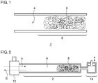
- Fig. 1 is a cross-sectional view of a pipe 2 according an embodiment.
- the pipe 2 is employed in a pneumatic system.
- the pipe 2 is configured as a resin tube, for example.
- At least a portion 6 of a pipe interior space 4 is filled with a metal wire 8 (which will be referred to as the "filled space").
- a metal wire 8 (which will be referred to as the "filled space").
- the material of the metal wire 8 a material having high thermal conductivity may preferably be employed. Specific examples of such a material include copper, aluminum, silver, and gold. From the cost viewpoint, copper may preferably be employed.
- the material of the pipe 2 is not restricted in particular. Examples of such a material of the pipe include metal materials in addition to resin materials.
- the metal wire 8 may preferably be configured to have a diameter of several ⁇ m to several hundred ⁇ m. More specifically, such a metal wire to be employed may preferably be configured to have a diameter of 20 ⁇ m to 50 ⁇ m. Also, as another embodiment, such a metal wire to be employed may preferably be configured to have a diameter of 1 ⁇ m to 100 ⁇ m.
- a space involving large pressure variation may preferably be selected as the filled space 6 to be filled with the metal wire 8.
- an end portion of the pipe 2 may preferably be selected as the filled space 6. More specifically, an end portion of the pipe 2 farther from an air pressure source may preferably be selected as the filled space 6.
- Fig. 2 is a diagram showing the operation of a pneumatic system including the pipe 2 shown in Fig. 1 .
- the pneumatic system 10 includes an electromagnetic valve 12 and a pneumatic actuator (pneumatic cylinder) 14 connected via the pipe 2.
- the electromagnetic valve 12 is configured to be switchable between an air supply mode and an air exhaust mode.
- compressed air flows into the pipe interior space 4 of the pipe 2 in a low-pressure state (indicated by the arrow A in the drawing).
- the air in the pipe interior space 4 is compressed, leading to the potential to raise the temperature of the air.
- Such an increase in the temperature is absorbed by the metal wire 8, and the thermal energy is stored by the metal wire 8.
- the thermal energy is stored in the metal wire 8 in the immediately previous step in the cycle. Accordingly, the thermal energy is discharged from the metal wire 8 to the air, thereby suppressing a reduction in the air temperature. In other words, it can be understood that the air expansion results in a reduction in the temperature of the metal wire 8.
- such an arrangement is capable of suppressing variation in the temperature.
- By suppressing variation in the temperature such an arrangement provides an advantage of suppressing degradation due to temperature variation.
- such an arrangement is capable of preventing the temperature in the pipe interior space from becoming lower than the dew point, thereby suppressing condensation. This suppresses the adverse effects of water droplets on the device operation characteristics, the device lifespan, and device reliability.
- Figs. 3A and 3B respectively show measurement results of temperature variation due to pressure variation in a case of employing the pipe 2 filled with the metal wire 8 and in a case of employing a pipe filled with no metal wire.
- the graph in the upper region in each drawing shows the temperature measurement result when the pressure was raised.
- the graph in the lower region in each drawing shows the temperature measurement result when the pressure was lowered.
- the pipe 2 employed in the experiment had an inner diameter of 5 mm, an outer diameter of 8 mm, and a length of 350 mm.
- the metal wire 8 was configured as a copper wire having a diameter of 20 ⁇ m.
- the interior space of the pipe 2 was filled with the metal wire 8 such that the region of the metal wire 8 extended over a length of 100 mm from the end of the pipe 2.
- the metal wire 8 was arranged as such a filler having a weight of 1.04 g and a fill ratio (volume ratio) of 5.91%.
- the pressure in the pipe interior space 4 was changed in a range between 20 kPa and 450 kPa (absolute value) in a period of 20 seconds.
- Temperature variation was measured using a K-type thermocouple and a thermocouple temperature converter (amplifier) having a response speed of 0.5 ms or less. It should be noted that the experiment was performed at a room temperature of 26°C, a humidity of 54%, and an atmospheric pressure of 1001 hPa on a clear day.
- such an arrangement involves a minimum temperature T MIN of -60°C, which leads to a saturated water vapor amount of 0.01 g/m 3 .
- T MIN minimum temperature
- Such an arrangement provides a saturated water vapor amount of 10 g/m 3 , which is three orders of magnitude greater than that in a case in which the metal wire 8 is not employed as a filler. This shows that, by employing the metal wire 8 as a filler, such an arrangement is capable of suppressing condensation.
- the pipe 2 employed in the experiment was configured as a resin pipe having an inner diameter of 5 mm and having a sealed end. As described above, the pipe 2 was configured such that its one end was sealed in order to simulate the effect of the pneumatic actuator (cylinder piston). With such an arrangement, the air supply operation and the air exhaust operation were performed via the other end in order to generate pressure variation in the pipe interior space 4.
- the air employed in this experiment had a relative humidity of 8% (at 20°C at atmospheric pressure).
- the metal wire 8 a copper wire having a diameter of 50 ⁇ m was employed. The experiment was made employing such a metal wire 8 with various fill ratios, i.e., with fill ratios of 0%, 4%, 6%, and 8%.
- Figs. 5A and 5B are diagrams each showing the relation between the copper wire fill ratio and the weight of remaining water droplets.
- the copper wire is employed as a filler with a fill ratio of 4%
- such an arrangement provides a reduction of nearly 30% in the weight of water droplets as compared with an arrangement in which no copper wire was employed as a filler.
- by raising the fill ratio up to 8% such an arrangement is capable of providing an 85% reduction in the water droplets.
- an arrangement of such a metal wire with a fill ratio of 8% is equivalent to a reduction in the pipe diameter ⁇ from 5 mm to 4.8 mm.
- the metal wire 8 is configured to have a further reduced diameter, e.g., to have a diameter on the order of 20 ⁇ m, this provides the metal wire 8 with a further increased surface area per volume.
- a further reduced diameter e.g., to have a diameter on the order of 20 ⁇ m.
- the metal wire 8 may be configured to have a further reduced diameter that is smaller than 20 ⁇ m.
- the metal wire 8 may be configured to have a diameter on the order of 1 ⁇ m. As the diameter of the metal wire 8 becomes smaller, its surface area becomes larger, which is preferable.
- the metal wire 8 is preferably configured to have a diameter of 1 ⁇ m or more from the viewpoint of mechanical strength, cost, commercial availability, and the like.
- the ratio of the surface area of the metal wire 8 with respect to the air volume stored in the pipe 2 is important to design the ratio of the surface area of the metal wire 8 with respect to the air volume stored in the pipe 2.
- Such an arrangement can be expected to provide the effect for suppressing condensation or the effect for suppressing temperature variation even in a case in which a metal wire having a diameter of 100 ⁇ m is provided as a filler with a fill ratio of 1%. That is to say, such a metal wire may preferably be provided as a filler such that the surface area of the metal wire per unit air volume is larger than 4 ⁇ 10 2 [m -1 ].
- a space to be filled with the metal wire 8 is not restricted to such an arrangement. Rather, the metal wire 8 may preferably be provided as a filler to a portion to be configured to suppress temperature variation or to suppress condensation. That is to say, the present invention is applicable to a pneumatic actuator in addition to such a pipe.
- a pneumatic actuator includes a cylinder and a piston.
- such a pneumatic actuator may further include a metal wire as a filler provided to an interior space of the cylinder
- a metal material (porous metal material) having a porous structure may be employed as a filler instead of or in addition to such a metal wire 8.
- a porous metal material has an advantage of providing an increased surface area ratio with respect to the volume, as with the metal wire.
- Such an arrangement provides an advantage of suppressing temperature variation and suppressing condensation with a small pressure loss tradeoff.
- the present invention is applicable to an pneumatic system.
Landscapes
- Engineering & Computer Science (AREA)
- General Engineering & Computer Science (AREA)
- Mechanical Engineering (AREA)
- Physics & Mathematics (AREA)
- Fluid Mechanics (AREA)
- Chemical & Material Sciences (AREA)
- Analytical Chemistry (AREA)
- Actuator (AREA)
- Pipe Accessories (AREA)
Abstract
A pipe 2 is employed in a pneumatic system. At least a portion 6 of an interior space 4 of the pipe 2 is filled with a metal wire 8. At least the portion 6 may be configured as an end of the pipe 2.
Description
- The present invention relates to a pipe employed in a pneumatic system and a pneumatic actuator.
- With a pneumatic system, in a case in which a pressurizing operation (inflow operation) and a depressurizing operation (outflow operation) are alternately and repeatedly performed, this leads to the occurrence of condensation in a pipe end or otherwise in a pneumatic actuator, resulting in a problem of remaining water droplets. Such remaining water droplets have adverse effects on the device operation characteristics, device lifespan, and device reliability. Accordingly, there is a need to provide a measure to solve such a problem (see non-patent document 1).
- Method employed in a pneumatic system for suppressing condensation, [online], SMC Corporation, [Retrieved on July 8, 2014], Internet <URL: http://www.smcworld.com/docs/technological_material/ja/pdf/341-P-01-11B.pdf>
- Examples of such measures to solve such a condensation problem include: a method in which the moisture of the supply air is further reduced, a method in which the material of the pipe is modified, a method employing a bypass line, a method employing a quick exhaust valve, and the like.
- The present invention has been made in view of such a situation. Accordingly, it is an exemplary purpose of an embodiment of the present invention to provide a pipe and a piston structured to suppress variation in the temperature in the pipe, and/or to suppress condensation.
- An embodiment of the present invention relates to a pipe employed in a pneumatic system. The pipe is structured such that at least a portion of an interior space thereof is filled with a wire-shaped metal material, i.e., a metal wire.
- With such an embodiment, the metal wire functions as a heat storage member, which allows temperature variation to be suppressed in the pipe interior space. Thus, such an arrangement is capable of suppressing condensation. In addition, by employing such a metal wire as a filler, such an arrangement provides an increased surface area while preventing an increase in pressure loss. This suppresses temperature variation in the pipe interior space and/or suppresses condensation.
- It should be noted that, in the present specification, examples of such a "pipe" include: (i) a pipe employed in a pneumatic system configured to transmit pressure between a given portion and a different portion; and (ii) an attachment having a small length, which is configured to connect a given pipe and another pipe, to change the direction of the pipe, or to prevent condensation or to prevent temperature variation.
- Also, the surface area of the metal material per unit volume of air may be larger than 4 × 10² [m-1].
- Also, the wire-shaped metal material may have a diameter of 100 µm or less. As the diameter of such a metal material becomes smaller, the surface area thereof becomes larger, which is preferable. However, such a wire-shaped metal material may have a diameter of 1 µm or more from the viewpoint of mechanical strength, cost, commercial availability, and the like.
- Also, the aforementioned portion of the interior space of the pipe may correspond to an end of the pipe.
- The water droplets readily remain at the end of the pipe. Thus, by providing such a portion with such a metal wire as a filler, such an arrangement is capable of suppressing condensation.
- Also, the aforementioned portion of the interior space of the pipe may correspond to a portion at which large pressure variation occurs. Such an arrangement is capable of suppressing temperature variation due to variation in pressure.
- The aforementioned portion may be filled with the metal wire with a fill ratio (volume ratio) of 1% to 8%. Such an arrangement provides an advantage of suppressing condensation while reducing the pressure loss tradeoff.
- Another embodiment of the present invention relates to a pneumatic actuator. The pneumatic actuator comprises a cylinder filled with a wire-shaped metal material.
- Yet another embodiment of the present invention relates to a pipe or otherwise a pneumatic actuator employed in a pneumatic system. At least a portion of the interior space of the pipe or the pneumatic actuator is filled with a carbon-based material such as a graphite material or the like.
- Also, the interior space of the pipe may be filled with a porous metal material instead of or in addition to such a metal wire.
- It should be noted that any combination of the aforementioned components or any manifestation of the present invention may be mutually substituted between a method, apparatus, and so forth, which are also effective as an embodiment of the present invention.
- With an embodiment of the present invention, such an arrangement is capable of suppressing condensation.
-
-
Fig. 1 is a cross-sectional view of a pipe according to an embodiment; -
Fig. 2 is a diagram showing the operation of a pneumatic system including the pipe shown inFig. 1 ; -
Figs. 3A and 3B are diagrams respectively showing the measurement results of temperature variation accompanying pressure variation obtained in a case of employing a pipe filled with a metal wire and in a case of employing a pipe having no metal wire as a filler; -
Fig. 4 is a diagram showing the relation between the temperature T and the amount of saturated water vapor amount α; and -
Figs. 5A and 5B are diagrams each showing the relation between the copper wire fill ratio and the weight of remaining water droplets. - Description will be made below regarding preferred embodiments according to the present invention with reference to the drawings. The same or similar components, members, and processes are denoted by the same reference numerals, and redundant description thereof will be omitted as appropriate. The embodiments have been described for exemplary purposes only, and are by no means intended to restrict the present invention. Also, it is not necessarily essential for the present invention that all the features or a combination thereof be provided as described in the embodiments.
-
Fig. 1 is a cross-sectional view of apipe 2 according an embodiment. Thepipe 2 is employed in a pneumatic system. Thepipe 2 is configured as a resin tube, for example. At least aportion 6 of apipe interior space 4 is filled with a metal wire 8 (which will be referred to as the "filled space"). As the material of themetal wire 8, a material having high thermal conductivity may preferably be employed. Specific examples of such a material include copper, aluminum, silver, and gold. From the cost viewpoint, copper may preferably be employed. In contrast, the material of thepipe 2 is not restricted in particular. Examples of such a material of the pipe include metal materials in addition to resin materials. Also, themetal wire 8 may preferably be configured to have a diameter of several µm to several hundred µm. More specifically, such a metal wire to be employed may preferably be configured to have a diameter of 20 µm to 50 µm. Also, as another embodiment, such a metal wire to be employed may preferably be configured to have a diameter of 1 µm to 100 µm. - A space involving large pressure variation may preferably be selected as the filled
space 6 to be filled with themetal wire 8. From another viewpoint, an end portion of thepipe 2 may preferably be selected as the filledspace 6. More specifically, an end portion of thepipe 2 farther from an air pressure source may preferably be selected as the filledspace 6. - The above is the structure of the
pipe 2. Next, description will be made regarding the mechanism thereof.Fig. 2 is a diagram showing the operation of a pneumatic system including thepipe 2 shown inFig. 1 . For example, thepneumatic system 10 includes anelectromagnetic valve 12 and a pneumatic actuator (pneumatic cylinder) 14 connected via thepipe 2. - The
electromagnetic valve 12 is configured to be switchable between an air supply mode and an air exhaust mode. When theelectromagnetic valve 12 is opened toward an air supply side port, compressed air flows into the pipeinterior space 4 of thepipe 2 in a low-pressure state (indicated by the arrow A in the drawing). In this stage, the air in the pipeinterior space 4 is compressed, leading to the potential to raise the temperature of the air. Such an increase in the temperature is absorbed by themetal wire 8, and the thermal energy is stored by themetal wire 8. - Subsequently, when the
electromagnetic valve 12 is opened toward the air exhaust side port, the compressed air stored in the pipeinterior space 4 is suddenly discharged (indicated by the arrow B in the drawing). This leads to a sudden drop in the pressure in the pipeinterior space 4 due to adiabatic expansion, resulting in a sudden reduction in the temperature. If the temperature thus lowered becomes lower than the dew point, this results in vapor generation. - With such an arrangement, the thermal energy is stored in the
metal wire 8 in the immediately previous step in the cycle. Accordingly, the thermal energy is discharged from themetal wire 8 to the air, thereby suppressing a reduction in the air temperature. In other words, it can be understood that the air expansion results in a reduction in the temperature of themetal wire 8. - As described above, by configuring the
pneumatic system 10 such that the interior space of thepipe 2 is filled with themetal wire 8, which is operated to repeatedly perform such a cycle of the air supply step and the air exhaust step, such an arrangement is capable of suppressing variation in the temperature. By suppressing variation in the temperature, such an arrangement provides an advantage of suppressing degradation due to temperature variation. - Furthermore, such an arrangement is capable of preventing the temperature in the pipe interior space from becoming lower than the dew point, thereby suppressing condensation. This suppresses the adverse effects of water droplets on the device operation characteristics, the device lifespan, and device reliability.
-
Figs. 3A and 3B respectively show measurement results of temperature variation due to pressure variation in a case of employing thepipe 2 filled with themetal wire 8 and in a case of employing a pipe filled with no metal wire. The graph in the upper region in each drawing shows the temperature measurement result when the pressure was raised. The graph in the lower region in each drawing shows the temperature measurement result when the pressure was lowered. - The
pipe 2 employed in the experiment had an inner diameter of 5 mm, an outer diameter of 8 mm, and a length of 350 mm. Themetal wire 8 was configured as a copper wire having a diameter of 20 µm. The interior space of thepipe 2 was filled with themetal wire 8 such that the region of themetal wire 8 extended over a length of 100 mm from the end of thepipe 2. Themetal wire 8 was arranged as such a filler having a weight of 1.04 g and a fill ratio (volume ratio) of 5.91%. The pressure in the pipeinterior space 4 was changed in a range between 20 kPa and 450 kPa (absolute value) in a period of 20 seconds. Temperature variation was measured using a K-type thermocouple and a thermocouple temperature converter (amplifier) having a response speed of 0.5 ms or less. It should be noted that the experiment was performed at a room temperature of 26°C, a humidity of 54%, and an atmospheric pressure of 1001 hPa on a clear day. - First, description will be made with reference to
Fig. 3B regarding temperature variation in a case of employing the pipe filled with nometal wire 8. In the pressurizing step, the temperature was raised to 100°C or more. Conversely, in the depressurizing step, the temperature was lowered to the vicinity of TMIN = -60°C. Accordingly, in a cycle in which the pressurizing step and the depressurizing step were alternately and repeatedly performed, the temperature of the pipe interior space varied in a range between -60°C and 100°C. - Next, description will be made with reference to
Fig. 3A regarding a case of employing thepipe 2 filled with themetal wire 8. By employing themetal wire 8 as a filler, such an arrangement is capable of suppressing temperature variation in a range of 6 to 7°C in both the pressurizing step and the depressurizing step. As described above, by employing themetal wire 8 as a filler, such an arrangement provides a marked effect for suppressing temperature variation. - In addition, in a case in which the
metal wire 8 is employed as a filler, such an arrangement is capable of relaxing a minimum value TMIN of the temperature of the pipe interior space on the order of 19°C in the depressurizing step, thereby providing an increased dew point. Thus, such an arrangement has the effect of suppressing the conditions for condensation. Using the Tetens equation and the equation of state, the saturation water vapor pressure E and the saturation water vapor amount α are represented by the following Expressions.Fig. 4 is a diagram showing the relation between the temperature T and the saturation water vapor amount α.

- In a case in which the
metal wire 8 is not employed as a filler, such an arrangement involves a minimum temperature TMIN of -60°C, which leads to a saturated water vapor amount of 0.01 g/m3. In contrast, in a case in which themetal wire 8 is employed as a filler, such an arrangement provides a minimum temperature TMIN of 19°C. Such an arrangement provides a saturated water vapor amount of 10 g/m3, which is three orders of magnitude greater than that in a case in which themetal wire 8 is not employed as a filler. This shows that, by employing themetal wire 8 as a filler, such an arrangement is capable of suppressing condensation. - Next, an experiment was performed for evaluating the effect of suppressing condensation. The
pipe 2 employed in the experiment was configured as a resin pipe having an inner diameter of 5 mm and having a sealed end. As described above, thepipe 2 was configured such that its one end was sealed in order to simulate the effect of the pneumatic actuator (cylinder piston). With such an arrangement, the air supply operation and the air exhaust operation were performed via the other end in order to generate pressure variation in the pipeinterior space 4. The air employed in this experiment had a relative humidity of 8% (at 20°C at atmospheric pressure). A cycle in which the pressure of the pipe interior space was changed from 500 kPa (G) to a vacuum pressure of -80 kPa was repeated, following which the weight of water droplets that were generated and remained in the pipe interior space was measured by means of an electronic scale. As themetal wire 8, a copper wire having a diameter of 50 µm was employed. The experiment was made employing such ametal wire 8 with various fill ratios, i.e., with fill ratios of 0%, 4%, 6%, and 8%. -
Figs. 5A and 5B are diagrams each showing the relation between the copper wire fill ratio and the weight of remaining water droplets. In a case in which the copper wire is employed as a filler with a fill ratio of 4%, such an arrangement provides a reduction of nearly 30% in the weight of water droplets as compared with an arrangement in which no copper wire was employed as a filler. Furthermore, by raising the fill ratio up to 8%, such an arrangement is capable of providing an 85% reduction in the water droplets. It should be noted that, from the viewpoint of flow resistance, an arrangement of such a metal wire with a fill ratio of 8% is equivalent to a reduction in the pipe diameter ϕ from 5 mm to 4.8 mm. Thus, it can be said that such an arrangement involves only a very small resistance loss (pressure loss). - It should be noted that dry air employed in factories has a relative humidity of 6%, which is lower than that employed in this experiment. Accordingly, in a case in which the
pipe 2 according to the embodiment is employed, such an arrangement allows the weight of water droplets to be further reduced. - In a case in which the
metal wire 8 is configured to have a further reduced diameter, e.g., to have a diameter on the order of 20 µm, this provides themetal wire 8 with a further increased surface area per volume. Thus, such an arrangement is capable of sufficiently suppressing temperature variation and/or of suppressing condensation even if themetal wire 8 is provided with a fill ratio that is lower than 4%, e.g., with a low fill ratio that is equal to or higher than 1%. Themetal wire 8 may be configured to have a further reduced diameter that is smaller than 20 µm. For example, themetal wire 8 may be configured to have a diameter on the order of 1 µm. As the diameter of themetal wire 8 becomes smaller, its surface area becomes larger, which is preferable. However, in practice, themetal wire 8 is preferably configured to have a diameter of 1 µm or more from the viewpoint of mechanical strength, cost, commercial availability, and the like. - In order to provide the effect of suppressing condensation and the effect of suppressing temperature variation, it is important to design the ratio of the surface area of the
metal wire 8 with respect to the air volume stored in thepipe 2. Description will be made below regarding an example in which thepipe 2 is uniformly filled with a metal wire having a radius r with a fill ratio x [%]. In this example, the volume V of the metal wire per unit volume of air stored in thepipe 2 is represented by V = 1 [m3] × x/100 = x/100 [m3]. Accordingly, the length L [m] of the metal wire is represented by L = x/100 ÷ πr2 = x/(100 × πr2) [m]. The surface area S[m2] is represented by L × 2πr = x/(50r) [m2]. Accordingly, the surface area of the metal wire per unit air volume is represented by the following Expression.
- Such an arrangement can be expected to provide the effect for suppressing condensation or the effect for suppressing temperature variation even in a case in which a metal wire having a diameter of 100 µm is provided as a filler with a fill ratio of 1%. That is to say, such a metal wire may preferably be provided as a filler such that the surface area of the metal wire per unit air volume is larger than 4 × 10² [m-1].
- Description has been made regarding the present invention with reference to the embodiments using specific terms. However, the above-described embodiments show only the mechanisms and applications of the present invention for exemplary purposes only, and are by no means intended to be interpreted restrictively. Rather, various modifications and various changes in the layout can be made without departing from the spirit and scope of the present invention defined in appended claims.
- Description has been made in the embodiment regarding an arrangement in which a portion of the interior space of the
pipe 2 is filled with themetal wire 8. However, a space to be filled with themetal wire 8 is not restricted to such an arrangement. Rather, themetal wire 8 may preferably be provided as a filler to a portion to be configured to suppress temperature variation or to suppress condensation. That is to say, the present invention is applicable to a pneumatic actuator in addition to such a pipe. Such a pneumatic actuator includes a cylinder and a piston. In a case in which the pneumatic actuator has the potential to have a problem of temperature variation or a problem of condensation in the interior space of the cylinder, such a pneumatic actuator may further include a metal wire as a filler provided to an interior space of the cylinder - Description has been made in the embodiment regarding an arrangement in which the
metal wire 8 is provided as a filler. Also, a metal material (porous metal material) having a porous structure may be employed as a filler instead of or in addition to such ametal wire 8. Such a porous metal material has an advantage of providing an increased surface area ratio with respect to the volume, as with the metal wire. Thus, such an arrangement provides an advantage of suppressing temperature variation and suppressing condensation with a small pressure loss tradeoff. - Description has been made in the embodiment and the modifications thereof regarding an arrangement in which a metal wire or a porous metal material is employed as a filler. Also, a carbon-based material having high thermal conductivity such as a graphite material may be employed as a filler instead of such a metal material.
- 2 pipe, 4 pipe interior space, 6 portion, 10 pneumatic system, 12 electromagnetic valve, 14 pneumatic actuator.
- The present invention is applicable to an pneumatic system.
Claims (7)
- A pipe employed in a pneumatic system, structured such that at least a portion of an interior space thereof is filled with a wire-shaped metal material or a porous metal material.
- The pipe according to Claim 1, wherein a surface area of the metal material per unit volume of air is larger than 4 × 10² [m-1].
- The pipe according to Claim 1 or 2, wherein the wire-shaped metal material has a diameter of 100 µm or less.
- The pipe according to any one of Claims 1 through 3, wherein the aforementioned portion of the interior space of the pipe corresponds to an end of the pipe.
- The pipe according to any one of Claims 1 through 3, wherein the aforementioned portion of the interior space of the pipe corresponds to a portion at which large pressure variation occurs.
- The pipe according to any one of Claims 1 through 3, wherein the aforementioned portion of the interior space of the pipe is filled with the wire-shaped metal material or the porous metal material with a fill ratio of 1% or more.
- A pneumatic actuator employed in a pneumatic system comprising a cylinder filled with a wire-shaped metal material or a porous metal material.
Applications Claiming Priority (2)
| Application Number | Priority Date | Filing Date | Title |
|---|---|---|---|
| JP2014170625A JP2016044771A (en) | 2014-08-25 | 2014-08-25 | Pneumatic system piping and pneumatic actuators |
| PCT/JP2015/073528 WO2016031711A1 (en) | 2014-08-25 | 2015-08-21 | Piping for pneumatic system and pneumatic actuator |
Publications (1)
| Publication Number | Publication Date |
|---|---|
| EP3187737A1 true EP3187737A1 (en) | 2017-07-05 |
Family
ID=55399604
Family Applications (1)
| Application Number | Title | Priority Date | Filing Date |
|---|---|---|---|
| EP15836141.0A Withdrawn EP3187737A1 (en) | 2014-08-25 | 2015-08-21 | Piping for pneumatic system and pneumatic actuator |
Country Status (3)
| Country | Link |
|---|---|
| EP (1) | EP3187737A1 (en) |
| JP (1) | JP2016044771A (en) |
| WO (1) | WO2016031711A1 (en) |
Family Cites Families (4)
| Publication number | Priority date | Publication date | Assignee | Title |
|---|---|---|---|---|
| JPS5135548Y1 (en) * | 1970-06-17 | 1976-09-01 | ||
| JPH041440Y2 (en) * | 1986-03-24 | 1992-01-17 | ||
| JP2000274405A (en) * | 1999-03-25 | 2000-10-03 | Kiyoshi Takaura | Air cylinder control device and control method |
| DE20314134U1 (en) * | 2003-09-10 | 2005-01-13 | Voss Automotive Gmbh | Pneumatic blow-off silencer |
-
2014
- 2014-08-25 JP JP2014170625A patent/JP2016044771A/en active Pending
-
2015
- 2015-08-21 EP EP15836141.0A patent/EP3187737A1/en not_active Withdrawn
- 2015-08-21 WO PCT/JP2015/073528 patent/WO2016031711A1/en not_active Ceased
Also Published As
| Publication number | Publication date |
|---|---|
| JP2016044771A (en) | 2016-04-04 |
| WO2016031711A1 (en) | 2016-03-03 |
Similar Documents
| Publication | Publication Date | Title |
|---|---|---|
| Al-Rubaiai et al. | A 3D-printed stretchable strain sensor for wind sensing | |
| EP2937592B1 (en) | Servicing monitoring system for mixed fluid-gas shock struts | |
| US8195336B2 (en) | Pressure regulator | |
| EP2516976B1 (en) | Fatigue resistant thermowell and methods | |
| WO2007022431A3 (en) | Test device for applying and measuring contact pressure on wires | |
| US20180164138A1 (en) | Flow rate calculation system and flow rate calculation method | |
| WO2015050958A3 (en) | Liquefier assembly for additive manufacturing systems, and methods of use thereof | |
| US9212963B2 (en) | Sensor water freeze protector | |
| Ahmed et al. | Thermal radiation effect on a transient MHD flow with mass transfer past an impulsively fixed infinite vertical plate | |
| EP2196787A2 (en) | High temperature sensor | |
| Peng et al. | Effect of scale parameter on the deflection of a nonlocal beam and application to energy release rate of a crack | |
| CN104102766A (en) | Ergun theory-based prediction method for breathability of parachute cloth fabric | |
| Guan et al. | A study on gaseous extinguishing agent sensing with a simple measurement method | |
| US11029269B2 (en) | Monitoring device | |
| JP4662372B2 (en) | Flow rate measuring method and flow rate measuring device | |
| JP6459430B2 (en) | Cooler | |
| US9482247B2 (en) | Apparatus and methods for determining a position of a piston in a cavity | |
| WO2016031711A1 (en) | Piping for pneumatic system and pneumatic actuator | |
| US9728057B2 (en) | Pneumatic detection using a liquefied compressed gas | |
| WO2006122694A3 (en) | Method for monitoring a fluid flow measurement and sensor system for measuring the flow of fluid | |
| EP2678650A1 (en) | Status indicator for temperature-sensitive goods | |
| WO2013157295A1 (en) | External force computation method | |
| JP2010156582A (en) | Test tool, testing device and test method | |
| HÖGBERG et al. | Linear feedback control and estimation of transition in plane channel flow | |
| EP4098989B1 (en) | Leakage detection |
Legal Events
| Date | Code | Title | Description |
|---|---|---|---|
| PUAI | Public reference made under article 153(3) epc to a published international application that has entered the european phase |
Free format text: ORIGINAL CODE: 0009012 |
|
| STAA | Information on the status of an ep patent application or granted ep patent |
Free format text: STATUS: THE APPLICATION HAS BEEN WITHDRAWN |
|
| 17P | Request for examination filed |
Effective date: 20170302 |
|
| AK | Designated contracting states |
Kind code of ref document: A1 Designated state(s): AL AT BE BG CH CY CZ DE DK EE ES FI FR GB GR HR HU IE IS IT LI LT LU LV MC MK MT NL NO PL PT RO RS SE SI SK SM TR |
|
| AX | Request for extension of the european patent |
Extension state: BA ME |
|
| 18W | Application withdrawn |
Effective date: 20170602 |