EP3187699A2 - Auto thermal valve (atv) for dual mode passive cooling flow modulation - Google Patents
Auto thermal valve (atv) for dual mode passive cooling flow modulation Download PDFInfo
- Publication number
- EP3187699A2 EP3187699A2 EP16204159.4A EP16204159A EP3187699A2 EP 3187699 A2 EP3187699 A2 EP 3187699A2 EP 16204159 A EP16204159 A EP 16204159A EP 3187699 A2 EP3187699 A2 EP 3187699A2
- Authority
- EP
- European Patent Office
- Prior art keywords
- auto thermal
- cooling
- gas flow
- thermal valve
- valve
- Prior art date
- Legal status (The legal status is an assumption and is not a legal conclusion. Google has not performed a legal analysis and makes no representation as to the accuracy of the status listed.)
- Granted
Links
- 238000001816 cooling Methods 0.000 title claims abstract description 38
- 230000009977 dual effect Effects 0.000 title claims abstract description 12
- 239000007789 gas Substances 0.000 claims abstract description 70
- 239000000112 cooling gas Substances 0.000 claims abstract description 40
- 230000001419 dependent effect Effects 0.000 claims abstract description 21
- 239000000463 material Substances 0.000 claims description 15
- XUIMIQQOPSSXEZ-UHFFFAOYSA-N Silicon Chemical compound [Si] XUIMIQQOPSSXEZ-UHFFFAOYSA-N 0.000 claims description 4
- 239000013529 heat transfer fluid Substances 0.000 claims description 4
- 229910052710 silicon Inorganic materials 0.000 claims description 4
- 239000010703 silicon Substances 0.000 claims description 4
- 241000083700 Ambystoma tigrinum virus Species 0.000 description 7
- 239000000567 combustion gas Substances 0.000 description 5
- 230000007423 decrease Effects 0.000 description 4
- 239000012530 fluid Substances 0.000 description 3
- 230000008602 contraction Effects 0.000 description 2
- 238000000034 method Methods 0.000 description 2
- 238000010586 diagram Methods 0.000 description 1
- 238000006073 displacement reaction Methods 0.000 description 1
- 239000000446 fuel Substances 0.000 description 1
- 230000006870 function Effects 0.000 description 1
- 239000002184 metal Substances 0.000 description 1
- 239000000203 mixture Substances 0.000 description 1
- 238000010248 power generation Methods 0.000 description 1
- -1 steam Substances 0.000 description 1
- 238000011144 upstream manufacturing Methods 0.000 description 1
- 238000003466 welding Methods 0.000 description 1
Images




Classifications
-
- F—MECHANICAL ENGINEERING; LIGHTING; HEATING; WEAPONS; BLASTING
- F16—ENGINEERING ELEMENTS AND UNITS; GENERAL MEASURES FOR PRODUCING AND MAINTAINING EFFECTIVE FUNCTIONING OF MACHINES OR INSTALLATIONS; THERMAL INSULATION IN GENERAL
- F16K—VALVES; TAPS; COCKS; ACTUATING-FLOATS; DEVICES FOR VENTING OR AERATING
- F16K11/00—Multiple-way valves, e.g. mixing valves; Pipe fittings incorporating such valves
- F16K11/02—Multiple-way valves, e.g. mixing valves; Pipe fittings incorporating such valves with all movable sealing faces moving as one unit
- F16K11/04—Multiple-way valves, e.g. mixing valves; Pipe fittings incorporating such valves with all movable sealing faces moving as one unit comprising only lift valves
- F16K11/044—Multiple-way valves, e.g. mixing valves; Pipe fittings incorporating such valves with all movable sealing faces moving as one unit comprising only lift valves with movable valve members positioned between valve seats
-
- F—MECHANICAL ENGINEERING; LIGHTING; HEATING; WEAPONS; BLASTING
- F02—COMBUSTION ENGINES; HOT-GAS OR COMBUSTION-PRODUCT ENGINE PLANTS
- F02C—GAS-TURBINE PLANTS; AIR INTAKES FOR JET-PROPULSION PLANTS; CONTROLLING FUEL SUPPLY IN AIR-BREATHING JET-PROPULSION PLANTS
- F02C9/00—Controlling gas-turbine plants; Controlling fuel supply in air- breathing jet-propulsion plants
- F02C9/16—Control of working fluid flow
- F02C9/18—Control of working fluid flow by bleeding, bypassing or acting on variable working fluid interconnections between turbines or compressors or their stages
-
- F—MECHANICAL ENGINEERING; LIGHTING; HEATING; WEAPONS; BLASTING
- F01—MACHINES OR ENGINES IN GENERAL; ENGINE PLANTS IN GENERAL; STEAM ENGINES
- F01D—NON-POSITIVE DISPLACEMENT MACHINES OR ENGINES, e.g. STEAM TURBINES
- F01D11/00—Preventing or minimising internal leakage of working-fluid, e.g. between stages
- F01D11/08—Preventing or minimising internal leakage of working-fluid, e.g. between stages for sealing space between rotor blade tips and stator
- F01D11/14—Adjusting or regulating tip-clearance, i.e. distance between rotor-blade tips and stator casing
- F01D11/16—Adjusting or regulating tip-clearance, i.e. distance between rotor-blade tips and stator casing by self-adjusting means
- F01D11/18—Adjusting or regulating tip-clearance, i.e. distance between rotor-blade tips and stator casing by self-adjusting means using stator or rotor components with predetermined thermal response, e.g. selective insulation, thermal inertia, differential expansion
-
- F—MECHANICAL ENGINEERING; LIGHTING; HEATING; WEAPONS; BLASTING
- F01—MACHINES OR ENGINES IN GENERAL; ENGINE PLANTS IN GENERAL; STEAM ENGINES
- F01D—NON-POSITIVE DISPLACEMENT MACHINES OR ENGINES, e.g. STEAM TURBINES
- F01D11/00—Preventing or minimising internal leakage of working-fluid, e.g. between stages
- F01D11/08—Preventing or minimising internal leakage of working-fluid, e.g. between stages for sealing space between rotor blade tips and stator
- F01D11/14—Adjusting or regulating tip-clearance, i.e. distance between rotor-blade tips and stator casing
- F01D11/20—Actively adjusting tip-clearance
- F01D11/24—Actively adjusting tip-clearance by selectively cooling-heating stator or rotor components
-
- F—MECHANICAL ENGINEERING; LIGHTING; HEATING; WEAPONS; BLASTING
- F01—MACHINES OR ENGINES IN GENERAL; ENGINE PLANTS IN GENERAL; STEAM ENGINES
- F01D—NON-POSITIVE DISPLACEMENT MACHINES OR ENGINES, e.g. STEAM TURBINES
- F01D25/00—Component parts, details, or accessories, not provided for in, or of interest apart from, other groups
- F01D25/08—Cooling; Heating; Heat-insulation
- F01D25/12—Cooling
-
- F—MECHANICAL ENGINEERING; LIGHTING; HEATING; WEAPONS; BLASTING
- F01—MACHINES OR ENGINES IN GENERAL; ENGINE PLANTS IN GENERAL; STEAM ENGINES
- F01D—NON-POSITIVE DISPLACEMENT MACHINES OR ENGINES, e.g. STEAM TURBINES
- F01D25/00—Component parts, details, or accessories, not provided for in, or of interest apart from, other groups
- F01D25/08—Cooling; Heating; Heat-insulation
- F01D25/14—Casings modified therefor
-
- F—MECHANICAL ENGINEERING; LIGHTING; HEATING; WEAPONS; BLASTING
- F01—MACHINES OR ENGINES IN GENERAL; ENGINE PLANTS IN GENERAL; STEAM ENGINES
- F01D—NON-POSITIVE DISPLACEMENT MACHINES OR ENGINES, e.g. STEAM TURBINES
- F01D5/00—Blades; Blade-carrying members; Heating, heat-insulating, cooling or antivibration means on the blades or the members
- F01D5/12—Blades
- F01D5/14—Form or construction
- F01D5/18—Hollow blades, i.e. blades with cooling or heating channels or cavities; Heating, heat-insulating or cooling means on blades
-
- F—MECHANICAL ENGINEERING; LIGHTING; HEATING; WEAPONS; BLASTING
- F02—COMBUSTION ENGINES; HOT-GAS OR COMBUSTION-PRODUCT ENGINE PLANTS
- F02C—GAS-TURBINE PLANTS; AIR INTAKES FOR JET-PROPULSION PLANTS; CONTROLLING FUEL SUPPLY IN AIR-BREATHING JET-PROPULSION PLANTS
- F02C7/00—Features, components parts, details or accessories, not provided for in, or of interest apart form groups F02C1/00 - F02C6/00; Air intakes for jet-propulsion plants
- F02C7/12—Cooling of plants
- F02C7/16—Cooling of plants characterised by cooling medium
- F02C7/18—Cooling of plants characterised by cooling medium the medium being gaseous, e.g. air
-
- F—MECHANICAL ENGINEERING; LIGHTING; HEATING; WEAPONS; BLASTING
- F16—ENGINEERING ELEMENTS AND UNITS; GENERAL MEASURES FOR PRODUCING AND MAINTAINING EFFECTIVE FUNCTIONING OF MACHINES OR INSTALLATIONS; THERMAL INSULATION IN GENERAL
- F16K—VALVES; TAPS; COCKS; ACTUATING-FLOATS; DEVICES FOR VENTING OR AERATING
- F16K31/00—Actuating devices; Operating means; Releasing devices
- F16K31/002—Actuating devices; Operating means; Releasing devices actuated by temperature variation
-
- Y—GENERAL TAGGING OF NEW TECHNOLOGICAL DEVELOPMENTS; GENERAL TAGGING OF CROSS-SECTIONAL TECHNOLOGIES SPANNING OVER SEVERAL SECTIONS OF THE IPC; TECHNICAL SUBJECTS COVERED BY FORMER USPC CROSS-REFERENCE ART COLLECTIONS [XRACs] AND DIGESTS
- Y02—TECHNOLOGIES OR APPLICATIONS FOR MITIGATION OR ADAPTATION AGAINST CLIMATE CHANGE
- Y02T—CLIMATE CHANGE MITIGATION TECHNOLOGIES RELATED TO TRANSPORTATION
- Y02T50/00—Aeronautics or air transport
- Y02T50/60—Efficient propulsion technologies, e.g. for aircraft
Definitions
- the disclosure relates generally to turbomachines, and more particularly, to an auto thermal valve (ATV) for dual mode passive cooling flow modulation.
- ATV auto thermal valve
- Turbines are widely used in a variety of aviation, industrial, and power generation applications to perform work.
- Each turbine generally includes alternating stages of peripherally mounted stator vanes and rotating blades.
- the stator vanes may be attached to a stationary component such as a casing that surrounds the turbine, and the rotating blades may be attached to a rotor located along an axial centerline of the turbine.
- a compressed working fluid such as steam, combustion gases, or air, flows along a gas path through the turbine to produce work.
- the stator vanes accelerate and direct the compressed working fluid onto a subsequent stage of rotating blades to impart motion to the rotating blades, thus turning the rotor and performing work. If any compressed working fluid moves radially outside of the desired flow path, the efficiency of the turbine may be reduced.
- the casing surrounding the turbine often includes a radially inner shell of shrouds, often formed in segments.
- the shrouds surround and define the outer perimeter of the hot gas path and may be located around both stator vanes and rotating blades.
- Turbine shrouds and other turbine components are typically cooled in some fashion to remove heat transferred by the hot gas path.
- a gas such as compressed air from an upstream compressor may be supplied through at least one cooling circuit including one or more cooling passages to cool the turbine shroud and other turbine components.
- Tuning pins may be used to control the flow of cooling gas passing through the cooling passages.
- the flow of cooling gas may be controlled using the tuning pins according to the operational conditions of the turbine (e.g., a higher flow of cooling gas may be required on a hot day, while a lower flow of cooling gas may be required on a cool day).
- Such flow control may be provided by manually adjusting the tuning pins to regulate the flow of cooling gas as needed.
- a first aspect of the disclosure provides an auto thermal valve (ATV) for dual mode passive cooling flow modulation, including: a gas flow inlet port; a gas flow outlet port; a temperature dependent expandable element; a rod coupled to the temperature expandable element; and a valve disc coupled to a distal end of the rod, the temperature dependent expandable element displacing the valve disc in response to a change in temperature; wherein the valve disc is displaced away from a valve seat by the temperature dependent expandable element at temperatures above and below a range of temperatures to allow a flow of cooling gas to pass from the gas flow inlet port to the gas flow outlet port.
- ATV auto thermal valve
- a second aspect of the disclosure provides cooling system for a turbine, including: a cooling circuit for cooling a component of the turbine; and an auto thermal valve for dual mode passive cooling flow modulation, the auto thermal valve comprising: a gas flow inlet port; a gas flow outlet port; a temperature dependent expandable element; a rod coupled to the temperature expandable element; and a valve disc coupled to a distal end of the rod, the temperature dependent expandable element displacing the valve disc in response to a change in temperature; wherein the valve disc is displaced away from a valve seat by the temperature dependent expandable element at temperatures above and below a range of temperatures to allow a flow of cooling gas to pass from the gas flow inlet port to the gas flow outlet port into the cooling circuit.
- a third aspect of the disclosure provides an auto thermal valve system for dual mode passive cooling flow modulation in a turbine, including: a first auto thermal valve including: a gas flow inlet port; a gas flow outlet port; a temperature dependent expandable element; a rod coupled to the temperature expandable element; and a valve disc coupled to a distal end of the rod, the temperature dependent expandable element displacing the valve disc in response to a change in temperature; wherein the valve disc is displaced away from a valve seat by the temperature dependent expandable element at temperatures above a range of temperatures to allow a flow of cooling gas to pass from the gas flow inlet port to the gas flow outlet port; and a second auto thermal valve including: a gas flow inlet port; a gas flow outlet port; a temperature dependent expandable element; a rod coupled to the temperature expandable element of the second auto thermal valve; and a valve disc coupled to a distal end of the rod of the second auto thermal valve, the temperature dependent expandable element of the second auto thermal valve displacing the valve disc of the second auto
- the disclosure relates generally to turbomachines, and more particularly, to an auto thermal valve (ATV) for dual mode passive cooling flow modulation.
- ATV auto thermal valve
- FIG. 1 shows a schematic view of gas turbomachine 2 as may be used herein.
- the gas turbomachine 2 may include a compressor 4.
- the compressor 4 compresses an incoming flow of air 6.
- the compressor 4 delivers a flow of compressed air 8 to a combustor 10.
- the combustor 10 mixes the flow of compressed air 8 with a pressurized flow of fuel 12 and ignites the mixture to create a flow of combustion gases 14.
- the gas turbine system 2 may include any number of combustors 10.
- the flow of combustion gases 14 is in turn delivered to a turbine 16.
- the flow of combustion gases 14 drives the turbine 16 to produce mechanical work.
- the mechanical work produced in the turbine 16 drives the compressor 4 via a shaft 18, and may be used to drive an external load 20, such as an electrical generator and/or the like.
- FIG. 2 An example of a turbine bucket 22 of the turbine 16 ( FIG. 1 ) is depicted in FIG. 2 .
- the turbine bucket 22 includes a base 24 and a blade 26 coupled to and extending radially outward from the base 24.
- a shroud 28 is positioned adjacent the blade 26 to limit the flow of combustion gas bypassing the turbine bucket 22 and not producing any useful work.
- the shroud 28 may be attached to a casing (not shown).
- the shroud 28, blade 26, and/or other turbine components within the hot gas path may be cooled using a flow of cooling gas 30 (e.g., air).
- the flow of cooling gas 30 may be supplied by the compressor 4 of the gas turbomachine 2 and may be provided to/into the shroud 28, blade 26, and/or other turbine components via a set of cooling passages.
- One such cooling passage 32 in the shroud 28 is depicted in FIG. 2 .
- the flow of cooling gas 30 into/through various components of the turbine 16 may be controlled using a set (i.e., one or more) of auto thermal valves (ATV) 40, which provide passive cooling flow modulation.
- ATVs 40 may be used, for example, to provide passive flow modulation for hot day wheelspace (WS) and metal temperature control and for cold day backflow margin (BFM) flow control.
- the ATVs 40 eliminate the need for the above-described tuning pins, which are not capable of providing such passive flow modulation.
- any number of ATVs 40 may be used to control the flow of cooling gas in the turbine 16.
- the passive flow modulation provided by the ATV 40 provides cooling flow savings across the operating range of the turbine 16 and improves the output and efficiency of the turbine 16. Further, unlike tuning pins, the ATV 40 does not require manual field tuning for different operational conditions, thereby reducing operating costs.
- FIGS. 3-5 An ATV 40 for providing dual mode passive cooling flow modulation is depicted in FIGS. 3-5 .
- the ATV 40 includes a valve section 42 including one or more gas flow inlet ports 44 and a gas flow outlet port 46.
- the ATV 40 further includes a housing 48 enclosing a bellows or other expandable element 50 containing a thermally expandable material 52.
- the thermally expandable material 52 may include, for example, a silicon heat transfer fluid. Any other suitable thermally expandable material 52 that is stable at the operating temperatures of the turbine 16 (e.g., up to 1300 °F) may also be used.
- the expandable element 50 is coupled to a rod 54.
- a valve disc 56 is provided at a distal end of the rod 54.
- the valve disc 56 may include, for example, a central cylindrical section 64 including an outer surface 58, and opposing frusto-conical end sections 66, 68.
- Other suitable configurations of the valve disc 56 capable of providing the functionality described herein may also be used.
- a fixed portion 30 Fixed ( FIG. 2 ) of the flow of cooling gas 30 may be provided to the downstream cooling passage 32 ( FIG. 1 ) for cooling purposes.
- An additional modulated portion 30 Mod ( FIG. 2 ) of the flow of cooling gas 30 may be selectively provided to the downstream cooling passage 32 via the ATV 40, depending on ambient temperature and/or other factors.
- the ATV 40 is shown in a closed configuration in FIG. 3 . That is, in the closed configuration, at least a portion of the outer surface 58 of the valve disc 56 engages at least a portion of the valve seat 60. In the closed configuration, the flow of cooling gas 30 Mod is prevented from flowing from the gas flow inlet ports 44 through a valve seat opening 62 and the gas flow outlet port 46 into the downstream cooling passage 32.
- FIG. 7 there is shown a chart illustrating temperature-based modulation of the flow of cooling gas 30 Mod through an ATV 40, according to embodiments.
- the flow of cooling gas 30 Mod through the ATV 40 may be in addition to a fixed flow of cooling gas 30 Fixed .
- Section A of the chart, in which there is no flow of cooling gas 30 Mod through the ATV 40, corresponds to the ATV 40 in a closed configuration for a first range of temperatures (e.g., as shown in FIG. 3 ).
- an increase in temperature at the ATV 40 causes an enlargement of the thermally expandable material 52 within the expandable element 50.
- This causes the expandable element 50 to extend within the housing 48 as indicated by arrow 70, forcing the rod 54 and valve disc 56 laterally away from the valve seat 60 towards the gas flow outlet port 46.
- a flow of cooling gas 30 Mod begins to flow from the gas flow inlet ports 44 through the valve seat opening 62 and the gas flow outlet port 46 into the downstream cooling passage 32 ( FIG. 2 ).
- the flow of cooling gas 30 Mod increases as the valve disc 56 moves farther away from the valve seat 60 (as the temperature further increases) as more flow area is provided between the frusto-conical end section 66 of the valve disc 56 and the valve seat 60.
- Section B of the chart in FIG. 7 depicts the increase in the flow of cooling gas 30 Mod through the ATV 40 for a second, higher range of temperatures.
- a decrease in temperature causes a contraction of the thermally expandable material 50 within the expandable element 50.
- This causes the expandable element 50 to contract within the housing 48 as indicated by arrow 72, forcing the rod 54 and valve disc 56 laterally away from the valve seat 60 and the gas flow outlet port 46.
- a flow of cooling gas 30 Mod begins to flow from the gas flow inlet ports 44 through the valve seat opening 62 and the gas flow outlet port 46 into the downstream cooling passage 32 ( FIG. 2 ).
- the flow of cooling gas 30 Mod increases as the valve disc 56 moves farther away from the valve seat 60 (as the temperature further decreases) as more flow area is provided between the frusto-conical end section 68 of the valve disc 56 and the valve seat 60.
- Section C of the chart in FIG. 7 depicts the increase in the flow of cooling gas 30 Mod through the ATV 40 for a third, lower range of temperatures.
- the ATV 40 provides a flow of cooling gas 30 Mod in response to the temperature dependent displacement of the valve disc 56.
- the configuration of the valve disc 56 allows the cooling gas 30 Mod to flow through the ATV 40 to serve both functions of controlling BFM (cold day) and controlling WS temperatures (hot day), thereby providing dual mode functionality.
- a similar functionality may be provided using two individual ATVs in parallel, where one of the ATVs (e.g., ATV 140A, FIG. 8 ) is configured to displace a valve disc to an open position at high temperatures (and which is closed at low temperatures), while the second ATV (e.g., ATV 140B, FIG. 8 ) is configured to displace a valve disc to an open condition at low temperatures (and which is closed at high temperatures).
- the passive flow modulation provided by the ATVs 140A, 140B provides cooling flow savings across the operating range of the turbine 16 and improves the output and efficiency of the turbine 16. Further, unlike tuning pins, the ATVs 140A, 140B do not require manual field tuning, thereby reducing operating costs.
- the ATV 140A is depicted in a closed configuration in FIG. 9 and in an open configuration in FIG. 10 .
- the ATV 140A includes a valve section 142 including one or more gas flow inlet ports 144 and a gas flow outlet port 146.
- the ATV 140A further includes a housing 148 enclosing a bellows or other expandable element 150 containing a thermally expandable material 152.
- the thermally expandable material 152 may include, for example, a silicon heat transfer fluid. Any other suitable thermally expandable material 152 that is stable at the operating temperatures of the turbine 16 (e.g., up to 1300 °F) may also be used.
- the expandable element 150 is coupled to a rod 154.
- a valve disc 156 is provided at a distal end of the rod 154. As depicted in FIG. 9 , the valve disc 156 may have an inwardly directed arcuate surface 158. Other suitable configurations of the valve disc 156 capable of providing the functionality described herein may also be used.
- the ATV 140A is shown in a closed configuration in FIGS. 9 and 11 .
- the arcuate surface 158 of the valve disc 156 sealingly engages a corresponding circular valve seat 160 formed adjacent the gas flow outlet port 146.
- the valve disc 156 and valve seat 160 may have any suitable configuration capable of forming a seal to prevent the flow of gas through the gas flow outlet port 146.
- the flow of cooling gas 30 Mod is prevented from flowing from the gas flow inlet ports 144 through the gas flow outlet port 146 into the downstream cooling passage 32 ( FIG. 8 ).
- an increase in temperature at the ATV 140A causes an enlargement of the thermally expandable material 152 within the expandable element 150. This causes the expandable element 150 to extend within the housing 148 as indicated by arrow 170, forcing the rod 154 and valve disc 156 laterally away from the valve seat 160 and the gas flow outlet port 146. When the arcuate surface 158 of the valve disc 156 no longer forms a seal against the valve seat 160, a flow of cooling gas 30 Mod flows from the gas flow inlet ports 144 through the gas flow outlet port 146 and into the downstream cooling passage 32 ( FIG. 8 ).
- the flow of cooling gas 30 Mod increases as the valve disc 156 moves farther away from the valve seat 160 (e.g., in response to a further increase in temperature) as more flow area is provided between the arcuate surface 158 of the valve disc 156 and the valve seat 160.
- the ATV 140B is depicted in a closed configuration in FIG. 13 and in an open configuration in FIG. 14 .
- the ATV 140B includes a valve section 242 including one or more gas flow inlet ports 244 and a gas flow outlet port 246.
- the ATV 140B further includes a housing 148 enclosing a bellows or other expandable element 150 containing a thermally expandable material 152.
- the thermally expandable material 152 may include, for example, a silicon heat transfer fluid. Any other suitable thermally expandable material 152 that is stable at the operating temperatures of the turbine 16 (e.g., up to 1300 °F) may also be used.
- the expandable element 150 is coupled to a rod 154.
- a valve disc 256 is provided at a distal end of the rod 154. As depicted in FIG. 13 , the valve disc 256 may have an outwardly directed arcuate surface 258. Other suitable configurations of the valve disc 256 capable of providing the functionality described herein may also be used.
- the ATV 140B is shown in a closed configuration in FIG. 13 .
- the arcuate surface 258 of the valve disc 256 sealingly engages a corresponding circular valve seat 260 formed adjacent the gas flow outlet port 246.
- the valve disc 256 and valve seat 260 may have any suitable configuration capable of forming a seal to prevent the flow of gas through the gas flow outlet port 246.
- the flow of cooling gas 30 Mod is prevented from flowing from the gas flow inlet ports 244 through the gas flow outlet port 246 into the downstream cooling passage 32 ( FIG. 8 ).
- a decrease in temperature at the ATV 140B causes a contraction of the thermally expandable material 152 within the expandable element 150. This causes the expandable element 150 to contract within the housing 148 as indicated by arrow 172, forcing the rod 154 and valve disc 156 laterally away from the valve seat 260 and the gas flow outlet port 246.
- a flow of cooling gas 30 Mod flows from the gas flow inlet ports 244 through the gas flow outlet port 246 and into the downstream cooling passage 32 ( FIG. 8 ).
- the flow of cooling gas 30 Mod increases as the valve disc 256 moves farther away from the valve seat 260 (e.g., in response to a further decrease in temperature) as more flow area is provided between the arcuate surface 258 of the valve disc 256 and the valve seat 260.
- a passive auto pressure valve may be used in lieu of or in combination with the ATV valves 40, 140 described above.
- Such an APV is actuated by changes in pressure, rather than by changes in temperature.
- components described as being “coupled” to one another can be joined along one or more interfaces.
- these interfaces can include junctions between distinct components, and in other cases, these interfaces can include a solidly and/or integrally formed interconnection. That is, in some cases, components that are "coupled” to one another can be simultaneously formed to define a single continuous member.
- these coupled components can be formed as separate members and be subsequently joined through known processes (e.g., fastening, ultrasonic welding, bonding).
Landscapes
- Engineering & Computer Science (AREA)
- General Engineering & Computer Science (AREA)
- Mechanical Engineering (AREA)
- Chemical & Material Sciences (AREA)
- Combustion & Propulsion (AREA)
- Physics & Mathematics (AREA)
- Fluid Mechanics (AREA)
- Details Of Valves (AREA)
- Temperature-Responsive Valves (AREA)
- Turbine Rotor Nozzle Sealing (AREA)
Abstract
Description
- The disclosure relates generally to turbomachines, and more particularly, to an auto thermal valve (ATV) for dual mode passive cooling flow modulation.
- Turbines are widely used in a variety of aviation, industrial, and power generation applications to perform work. Each turbine generally includes alternating stages of peripherally mounted stator vanes and rotating blades. The stator vanes may be attached to a stationary component such as a casing that surrounds the turbine, and the rotating blades may be attached to a rotor located along an axial centerline of the turbine. A compressed working fluid, such as steam, combustion gases, or air, flows along a gas path through the turbine to produce work. The stator vanes accelerate and direct the compressed working fluid onto a subsequent stage of rotating blades to impart motion to the rotating blades, thus turning the rotor and performing work. If any compressed working fluid moves radially outside of the desired flow path, the efficiency of the turbine may be reduced. As a result, the casing surrounding the turbine often includes a radially inner shell of shrouds, often formed in segments. The shrouds surround and define the outer perimeter of the hot gas path and may be located around both stator vanes and rotating blades.
- Turbine shrouds and other turbine components (e.g., blades, nozzles, etc.) are typically cooled in some fashion to remove heat transferred by the hot gas path. A gas such as compressed air from an upstream compressor may be supplied through at least one cooling circuit including one or more cooling passages to cool the turbine shroud and other turbine components.
- Tuning pins may be used to control the flow of cooling gas passing through the cooling passages. The flow of cooling gas may be controlled using the tuning pins according to the operational conditions of the turbine (e.g., a higher flow of cooling gas may be required on a hot day, while a lower flow of cooling gas may be required on a cool day). Such flow control may be provided by manually adjusting the tuning pins to regulate the flow of cooling gas as needed.
- A first aspect of the disclosure provides an auto thermal valve (ATV) for dual mode passive cooling flow modulation, including: a gas flow inlet port; a gas flow outlet port; a temperature dependent expandable element; a rod coupled to the temperature expandable element; and a valve disc coupled to a distal end of the rod, the temperature dependent expandable element displacing the valve disc in response to a change in temperature; wherein the valve disc is displaced away from a valve seat by the temperature dependent expandable element at temperatures above and below a range of temperatures to allow a flow of cooling gas to pass from the gas flow inlet port to the gas flow outlet port.
- A second aspect of the disclosure provides cooling system for a turbine, including: a cooling circuit for cooling a component of the turbine; and an auto thermal valve for dual mode passive cooling flow modulation, the auto thermal valve comprising: a gas flow inlet port; a gas flow outlet port; a temperature dependent expandable element; a rod coupled to the temperature expandable element; and a valve disc coupled to a distal end of the rod, the temperature dependent expandable element displacing the valve disc in response to a change in temperature; wherein the valve disc is displaced away from a valve seat by the temperature dependent expandable element at temperatures above and below a range of temperatures to allow a flow of cooling gas to pass from the gas flow inlet port to the gas flow outlet port into the cooling circuit.
- A third aspect of the disclosure provides an auto thermal valve system for dual mode passive cooling flow modulation in a turbine, including: a first auto thermal valve including: a gas flow inlet port; a gas flow outlet port; a temperature dependent expandable element; a rod coupled to the temperature expandable element; and a valve disc coupled to a distal end of the rod, the temperature dependent expandable element displacing the valve disc in response to a change in temperature; wherein the valve disc is displaced away from a valve seat by the temperature dependent expandable element at temperatures above a range of temperatures to allow a flow of cooling gas to pass from the gas flow inlet port to the gas flow outlet port; and a second auto thermal valve including: a gas flow inlet port; a gas flow outlet port; a temperature dependent expandable element; a rod coupled to the temperature expandable element of the second auto thermal valve; and a valve disc coupled to a distal end of the rod of the second auto thermal valve, the temperature dependent expandable element of the second auto thermal valve displacing the valve disc of the second auto thermal valve in response to a change in temperature; wherein the valve disc of the second auto thermal valve is displaced away from a valve seat of the second auto thermal valve by the temperature dependent expandable element of the second auto thermal valve at temperatures below the range of temperatures to allow a flow of cooling gas to pass from the gas flow inlet port of the second auto thermal valve to the gas flow outlet port of the second auto thermal valve.
- The illustrative aspects of the present disclosure are designed to solve the problems herein described and/or other problems not discussed.
- These and other features of this disclosure will be more readily understood from the following detailed description of the various aspects of the disclosure taken in conjunction with the accompanying drawing that depicts various embodiments of the disclosure.
-
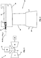
FIG. 1 is a schematic diagram of a gas turbine system, according to embodiments. -
FIG. 2 depicts a turbine bucket and shroud, according to embodiments. -
FIG. 3 depicts an auto thermal valve (ATV) in a closed configuration, according to embodiments. -
FIG. 4 depicts the ATV ofFIG. 3 in a hot ambient modulated flow configuration, according to embodiments. -
FIG. 5 depicts the ATV ofFIG. 3 in a cold ambient modulated flow configuration, according to embodiments. -
FIG. 6 depicts a valve disc, according to embodiments. -
FIG. 7 is a chart illustrating temperature-based modulation of a flow of cooling gas, according to embodiments. -
FIG. 8 depicts a turbine bucket and shroud, according to embodiments. -
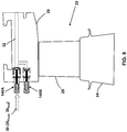
FIG. 9 depicts an ATV in a closed configuration, according to embodiments. -
FIG. 10 depicts the ATV ofFIG. 9 in an open configuration, according to embodiments. -
FIG. 11 is an end view of the ATV ofFIG. 9 , according to embodiments. -
FIG. 12 is an end view of the ATV ofFIG. 9 in an open configuration, according to embodiments. -
FIG. 13 depicts an ATV in a closed configuration, according to embodiments. -
FIG. 14 depicts the ATV ofFIG. 13 in an open configuration, according to embodiments. - It is noted that the drawing of the disclosure is not to scale. The drawing is intended to depict only typical aspects of the disclosure, and therefore should not be considered as limiting the scope of the disclosure. In the drawing, like numbering represents like elements between the drawings.
- The disclosure relates generally to turbomachines, and more particularly, to an auto thermal valve (ATV) for dual mode passive cooling flow modulation.
- Referring now to the drawings, in which like numerals refer to like elements throughout the several views,
FIG. 1 shows a schematic view ofgas turbomachine 2 as may be used herein. Thegas turbomachine 2 may include acompressor 4. Thecompressor 4 compresses an incoming flow ofair 6. - The
compressor 4 delivers a flow of compressedair 8 to acombustor 10. Thecombustor 10 mixes the flow of compressedair 8 with a pressurized flow offuel 12 and ignites the mixture to create a flow ofcombustion gases 14. Although only asingle combustor 10 is shown, thegas turbine system 2 may include any number ofcombustors 10. The flow ofcombustion gases 14 is in turn delivered to aturbine 16. The flow ofcombustion gases 14 drives theturbine 16 to produce mechanical work. The mechanical work produced in theturbine 16 drives thecompressor 4 via ashaft 18, and may be used to drive anexternal load 20, such as an electrical generator and/or the like. - An example of a
turbine bucket 22 of the turbine 16 (FIG. 1 ) is depicted inFIG. 2 . Theturbine bucket 22 includes abase 24 and ablade 26 coupled to and extending radially outward from thebase 24. Ashroud 28 is positioned adjacent theblade 26 to limit the flow of combustion gas bypassing theturbine bucket 22 and not producing any useful work. Theshroud 28 may be attached to a casing (not shown). - The
shroud 28,blade 26, and/or other turbine components within the hot gas path may be cooled using a flow of cooling gas 30 (e.g., air). The flow ofcooling gas 30 may be supplied by thecompressor 4 of thegas turbomachine 2 and may be provided to/into theshroud 28,blade 26, and/or other turbine components via a set of cooling passages. Onesuch cooling passage 32 in theshroud 28 is depicted inFIG. 2 . - According to embodiments, the flow of
cooling gas 30 into/through various components of theturbine 16 may be controlled using a set (i.e., one or more) of auto thermal valves (ATV) 40, which provide passive cooling flow modulation. TheATVs 40 may be used, for example, to provide passive flow modulation for hot day wheelspace (WS) and metal temperature control and for cold day backflow margin (BFM) flow control. TheATVs 40 eliminate the need for the above-described tuning pins, which are not capable of providing such passive flow modulation. Although only one ATV 40 is depicted inFIG. 2 , any number ofATVs 40 may be used to control the flow of cooling gas in theturbine 16. The passive flow modulation provided by the ATV 40 provides cooling flow savings across the operating range of theturbine 16 and improves the output and efficiency of theturbine 16. Further, unlike tuning pins, the ATV 40 does not require manual field tuning for different operational conditions, thereby reducing operating costs. - An
ATV 40 for providing dual mode passive cooling flow modulation is depicted inFIGS. 3-5 . As shown, the ATV 40 includes avalve section 42 including one or more gasflow inlet ports 44 and a gasflow outlet port 46. TheATV 40 further includes ahousing 48 enclosing a bellows or otherexpandable element 50 containing a thermallyexpandable material 52. The thermallyexpandable material 52 may include, for example, a silicon heat transfer fluid. Any other suitable thermallyexpandable material 52 that is stable at the operating temperatures of the turbine 16 (e.g., up to 1300 °F) may also be used. - The
expandable element 50 is coupled to arod 54. Avalve disc 56 is provided at a distal end of therod 54. As depicted inFIG. 6 , thevalve disc 56 may include, for example, a centralcylindrical section 64 including anouter surface 58, and opposing frusto-conical end sections valve disc 56 capable of providing the functionality described herein may also be used. - Generally, although not required, a fixed portion 30Fixed (
FIG. 2 ) of the flow of coolinggas 30 may be provided to the downstream cooling passage 32 (FIG. 1 ) for cooling purposes. An additional modulated portion 30Mod (FIG. 2 ) of the flow of coolinggas 30 may be selectively provided to thedownstream cooling passage 32 via theATV 40, depending on ambient temperature and/or other factors. - The
ATV 40 is shown in a closed configuration inFIG. 3 . That is, in the closed configuration, at least a portion of theouter surface 58 of thevalve disc 56 engages at least a portion of thevalve seat 60. In the closed configuration, the flow of coolinggas 30Mod is prevented from flowing from the gasflow inlet ports 44 through avalve seat opening 62 and the gasflow outlet port 46 into thedownstream cooling passage 32. - Referring temporarily to
FIG. 7 , there is shown a chart illustrating temperature-based modulation of the flow of coolinggas 30Mod through anATV 40, according to embodiments. As stated above, the flow of coolinggas 30Mod through theATV 40 may be in addition to a fixed flow of coolinggas 30Fixed. Section A of the chart, in which there is no flow of coolinggas 30Mod through theATV 40, corresponds to theATV 40 in a closed configuration for a first range of temperatures (e.g., as shown inFIG. 3 ). - Referring now to
FIG. 4 , an increase in temperature at theATV 40 causes an enlargement of the thermallyexpandable material 52 within theexpandable element 50. This causes theexpandable element 50 to extend within thehousing 48 as indicated byarrow 70, forcing therod 54 andvalve disc 56 laterally away from thevalve seat 60 towards the gasflow outlet port 46. When theouter surface 58 of the centralcylindrical section 64 of thevalve disc 56 no longer contacts thevalve seat 60, a flow of coolinggas 30Mod begins to flow from the gasflow inlet ports 44 through thevalve seat opening 62 and the gasflow outlet port 46 into the downstream cooling passage 32 (FIG. 2 ). The flow of coolinggas 30Mod increases as thevalve disc 56 moves farther away from the valve seat 60 (as the temperature further increases) as more flow area is provided between the frusto-conical end section 66 of thevalve disc 56 and thevalve seat 60. Section B of the chart inFIG. 7 depicts the increase in the flow of coolinggas 30Mod through theATV 40 for a second, higher range of temperatures. - As depicted in
FIG. 5 , a decrease in temperature causes a contraction of the thermallyexpandable material 50 within theexpandable element 50. This causes theexpandable element 50 to contract within thehousing 48 as indicated byarrow 72, forcing therod 54 andvalve disc 56 laterally away from thevalve seat 60 and the gasflow outlet port 46. When theouter surface 58 of the centralcylindrical section 64 of thevalve disc 56 no longer contacts thevalve seat 60, a flow of coolinggas 30Mod begins to flow from the gasflow inlet ports 44 through thevalve seat opening 62 and the gasflow outlet port 46 into the downstream cooling passage 32 (FIG. 2 ). The flow of coolinggas 30Mod increases as thevalve disc 56 moves farther away from the valve seat 60 (as the temperature further decreases) as more flow area is provided between the frusto-conical end section 68 of thevalve disc 56 and thevalve seat 60. Section C of the chart inFIG. 7 depicts the increase in the flow of coolinggas 30Mod through theATV 40 for a third, lower range of temperatures. - As depicted in
FIGS. 3-5 , theATV 40 provides a flow of coolinggas 30Mod in response to the temperature dependent displacement of thevalve disc 56. The configuration of thevalve disc 56 allows the coolinggas 30Mod to flow through theATV 40 to serve both functions of controlling BFM (cold day) and controlling WS temperatures (hot day), thereby providing dual mode functionality. - As detailed below, according to embodiments, a similar functionality may be provided using two individual ATVs in parallel, where one of the ATVs (e.g.,
ATV 140A,FIG. 8 ) is configured to displace a valve disc to an open position at high temperatures (and which is closed at low temperatures), while the second ATV (e.g.,ATV 140B,FIG. 8 ) is configured to displace a valve disc to an open condition at low temperatures (and which is closed at high temperatures). The passive flow modulation provided by theATVs turbine 16 and improves the output and efficiency of theturbine 16. Further, unlike tuning pins, theATVs - The
ATV 140A is depicted in a closed configuration inFIG. 9 and in an open configuration inFIG. 10 . TheATV 140A includes avalve section 142 including one or more gasflow inlet ports 144 and a gasflow outlet port 146. TheATV 140A further includes ahousing 148 enclosing a bellows or otherexpandable element 150 containing a thermallyexpandable material 152. The thermallyexpandable material 152 may include, for example, a silicon heat transfer fluid. Any other suitable thermallyexpandable material 152 that is stable at the operating temperatures of the turbine 16 (e.g., up to 1300 °F) may also be used. - The
expandable element 150 is coupled to arod 154. Avalve disc 156 is provided at a distal end of therod 154. As depicted inFIG. 9 , thevalve disc 156 may have an inwardly directedarcuate surface 158. Other suitable configurations of thevalve disc 156 capable of providing the functionality described herein may also be used. - The
ATV 140A is shown in a closed configuration inFIGS. 9 and 11 . In the closed configuration, thearcuate surface 158 of thevalve disc 156 sealingly engages a correspondingcircular valve seat 160 formed adjacent the gasflow outlet port 146. In general, thevalve disc 156 andvalve seat 160 may have any suitable configuration capable of forming a seal to prevent the flow of gas through the gasflow outlet port 146. In the closed configuration, the flow of coolinggas 30Mod is prevented from flowing from the gasflow inlet ports 144 through the gasflow outlet port 146 into the downstream cooling passage 32 (FIG. 8 ). - Referring now to
FIGS. 10 and 12 , an increase in temperature at theATV 140A causes an enlargement of the thermallyexpandable material 152 within theexpandable element 150. This causes theexpandable element 150 to extend within thehousing 148 as indicated byarrow 170, forcing therod 154 andvalve disc 156 laterally away from thevalve seat 160 and the gasflow outlet port 146. When thearcuate surface 158 of thevalve disc 156 no longer forms a seal against thevalve seat 160, a flow of coolinggas 30Mod flows from the gasflow inlet ports 144 through the gasflow outlet port 146 and into the downstream cooling passage 32 (FIG. 8 ). The flow of coolinggas 30Mod increases as thevalve disc 156 moves farther away from the valve seat 160 (e.g., in response to a further increase in temperature) as more flow area is provided between thearcuate surface 158 of thevalve disc 156 and thevalve seat 160. - The
ATV 140B is depicted in a closed configuration inFIG. 13 and in an open configuration inFIG. 14 . TheATV 140B includes avalve section 242 including one or more gasflow inlet ports 244 and a gasflow outlet port 246. TheATV 140B further includes ahousing 148 enclosing a bellows or otherexpandable element 150 containing a thermallyexpandable material 152. The thermallyexpandable material 152 may include, for example, a silicon heat transfer fluid. Any other suitable thermallyexpandable material 152 that is stable at the operating temperatures of the turbine 16 (e.g., up to 1300 °F) may also be used. - The
expandable element 150 is coupled to arod 154. Avalve disc 256 is provided at a distal end of therod 154. As depicted inFIG. 13 , thevalve disc 256 may have an outwardly directedarcuate surface 258. Other suitable configurations of thevalve disc 256 capable of providing the functionality described herein may also be used. - The
ATV 140B is shown in a closed configuration inFIG. 13 . In the closed configuration, thearcuate surface 258 of thevalve disc 256 sealingly engages a correspondingcircular valve seat 260 formed adjacent the gasflow outlet port 246. In general, thevalve disc 256 andvalve seat 260 may have any suitable configuration capable of forming a seal to prevent the flow of gas through the gasflow outlet port 246. In the closed configuration, the flow of coolinggas 30Mod is prevented from flowing from the gasflow inlet ports 244 through the gasflow outlet port 246 into the downstream cooling passage 32 (FIG. 8 ). - Referring now to
FIG. 14 , a decrease in temperature at theATV 140B causes a contraction of the thermallyexpandable material 152 within theexpandable element 150. This causes theexpandable element 150 to contract within thehousing 148 as indicated byarrow 172, forcing therod 154 andvalve disc 156 laterally away from thevalve seat 260 and the gasflow outlet port 246. When thearcuate surface 258 of thevalve disc 256 no longer forms a seal against thevalve seat 260, a flow of coolinggas 30Mod flows from the gasflow inlet ports 244 through the gasflow outlet port 246 and into the downstream cooling passage 32 (FIG. 8 ). The flow of coolinggas 30Mod increases as thevalve disc 256 moves farther away from the valve seat 260 (e.g., in response to a further decrease in temperature) as more flow area is provided between thearcuate surface 258 of thevalve disc 256 and thevalve seat 260. - According to embodiments, a passive auto pressure valve (APV) may be used in lieu of or in combination with the
ATV valves 40, 140 described above. Such an APV is actuated by changes in pressure, rather than by changes in temperature. - In various embodiments, components described as being "coupled" to one another can be joined along one or more interfaces. In some embodiments, these interfaces can include junctions between distinct components, and in other cases, these interfaces can include a solidly and/or integrally formed interconnection. That is, in some cases, components that are "coupled" to one another can be simultaneously formed to define a single continuous member. However, in other embodiments, these coupled components can be formed as separate members and be subsequently joined through known processes (e.g., fastening, ultrasonic welding, bonding).
- When an element or layer is referred to as being "on", "engaged to", "connected to" or "coupled to" another element, it may be directly on, engaged, connected or coupled to the other element, or intervening elements may be present. In contrast, when an element is referred to as being "directly on," "directly engaged to", "directly connected to" or "directly coupled to" another element, there may be no intervening elements or layers present. Other words used to describe the relationship between elements should be interpreted in a like fashion (e.g., "between" versus "directly between," "adjacent" versus "directly adjacent," etc.). As used herein, the term "and/or" includes any and all combinations of one or more of the associated listed items.
- The terminology used herein is for the purpose of describing particular embodiments only and is not intended to be limiting of the disclosure. As used herein, the singular forms "a", "an" and "the" are intended to include the plural forms as well, unless the context clearly indicates otherwise. It will be further understood that the terms "comprises" and/or "comprising," when used in this specification, specify the presence of stated features, integers, steps, operations, elements, and/or components, but do not preclude the presence or addition of one or more other features, integers, steps, operations, elements, components, and/or groups thereof.
- This written description uses examples to disclose the invention, including the best mode, and also to enable any person skilled in the art to practice the invention, including making and using any devices or systems and performing any incorporated methods. The patentable scope of the invention is defined by the claims, and may include other examples that occur to those skilled in the art. Such other examples are intended to be within the scope of the claims if they have structural elements that do not differ from the literal language of the claims, or if they include equivalent structural elements with insubstantial differences from the literal languages of the claims.
Claims (10)
- An auto thermal valve for dual mode passive cooling flow modulation, comprising:a gas flow inlet port (44, 144, 244);a gas flow outlet port (46, 146, 246);a temperature dependent expandable element (50, 150);a rod (54, 154) coupled to the temperature expandable element (50, 150); anda valve disc (56, 156, 256) coupled to a distal end of the rod (54, 154), the temperature dependent expandable element (50, 150) displacing the valve disc (56, 156, 256) in response to a change in temperature;wherein the valve disc (56, 156, 256) is displaced away from a valve seat (60, 160, 260) by the temperature dependent expandable element (50, 150) at temperatures above and below a range of temperatures to allow a flow of cooling gas (30) to pass from the gas flow inlet port (44, 144, 244) to the gas flow outlet port (46, 146, 246).
- The auto thermal valve according to claim 1, wherein the flow of cooling gas (30) passing from the gas flow inlet port (44, 144, 244) to the gas flow outlet port (46, 146, 246) increases as the temperature moves away from the range of temperatures.
- The auto thermal valve according to claim 1 or 2, wherein the valve disc (56, 156, 256) engages the valve seat (60, 160, 260) to block the flow of cooling gas (30) from flowing from the gas flow inlet port (44, 144, 244) to the gas flow outlet port (46, 146, 246) at temperatures within the range of temperatures.
- The auto thermal valve according to any of claims 1 to 3, wherein the temperature dependent expandable element (50, 150) contains a thermally expandable material (52, 152).
- The auto thermal valve according to claim 4, wherein the thermally expandable material (52, 152) comprises a silicon heat transfer fluid.
- The auto thermal valve according to any of claims 1 to 5, wherein the temperature dependent expandable element (50, 150) comprises a bellows.
- The auto thermal valve according to any preceding claim, wherein the valve disc (56, 156, 256) comprises a central cylindrical section (64) and opposing frusto-conical end sections.
- A cooling system for a turbine (16), comprising:a cooling circuit for cooling at least one component of the turbine (16); andan auto thermal valve for dual mode passive cooling flow modulation, the auto thermal valve as recited in any preceding claim:and wherein the flow of cooling gas (30, 30Fixed, 30Mod) passes from the gas flow inlet port to the gas flow outlet port (46, 146, 246) into the cooling circuit.
- An auto thermal valve system for dual mode passive cooling flow modulation in a turbine (16), comprising:a first auto thermal valve as received in any of claims 1 to 7, anda second auto thermal valve as defined in any of claims 1 to 7.
- The auto thermal valve system according to claim 9, wherein the first auto thermal valve and the second auto thermal valve are coupled to a cooling system of a turbine.
Applications Claiming Priority (1)
| Application Number | Priority Date | Filing Date | Title |
|---|---|---|---|
| US14/983,768 US10337411B2 (en) | 2015-12-30 | 2015-12-30 | Auto thermal valve (ATV) for dual mode passive cooling flow modulation |
Publications (3)
| Publication Number | Publication Date |
|---|---|
| EP3187699A2 true EP3187699A2 (en) | 2017-07-05 |
| EP3187699A3 EP3187699A3 (en) | 2017-08-16 |
| EP3187699B1 EP3187699B1 (en) | 2020-02-12 |
Family
ID=57570154
Family Applications (1)
| Application Number | Title | Priority Date | Filing Date |
|---|---|---|---|
| EP16204159.4A Active EP3187699B1 (en) | 2015-12-30 | 2016-12-14 | Auto thermal valve (atv) for dual mode passive cooling flow modulation |
Country Status (4)
| Country | Link |
|---|---|
| US (1) | US10337411B2 (en) |
| EP (1) | EP3187699B1 (en) |
| JP (1) | JP7130354B2 (en) |
| CN (1) | CN107013705B (en) |
Families Citing this family (6)
| Publication number | Priority date | Publication date | Assignee | Title |
|---|---|---|---|---|
| EP3351735B1 (en) * | 2017-01-23 | 2023-10-18 | MTU Aero Engines AG | Turbomachine housing element |
| CN110005843B (en) * | 2019-04-24 | 2020-06-09 | 博纳斯威阀门股份有限公司 | Circulating air guide valve |
| FR3095831B1 (en) * | 2019-05-10 | 2023-09-01 | Safran Aircraft Engines | improved turbomachine module ventilation device |
| US11008979B2 (en) * | 2019-05-29 | 2021-05-18 | Raytheon Technologies Corporation | Passive centrifugal bleed valve system for a gas turbine engine |
| US11989043B2 (en) | 2021-08-30 | 2024-05-21 | Kalsi Engineering, Inc. | Miniature passive thermal control valve for mixing or splitting single-phase fluid with adjustable thermal actuator |
| US20240255059A1 (en) | 2023-01-30 | 2024-08-01 | Rolls-Royce North American Technologies Inc. | Double bellows valve for preventing undesired valve failure positions |
Family Cites Families (95)
| Publication number | Priority date | Publication date | Assignee | Title |
|---|---|---|---|---|
| US799256A (en) | 1905-05-01 | 1905-09-12 | Levin S Parker | Suction-dredge. |
| US2659198A (en) | 1950-08-04 | 1953-11-17 | Harvey A Cook | Explosion-cycle inducer-disk valve turbojet engine for aircraft propulsion |
| US2787440A (en) * | 1953-05-21 | 1957-04-02 | Westinghouse Electric Corp | Turbine apparatus |
| US3004494A (en) | 1957-11-14 | 1961-10-17 | Thompson Ramo Wooldridge Inc | Turbine driven pump inducer |
| US3733816A (en) | 1971-06-11 | 1973-05-22 | Chandler Evans Inc | Pump operated cooling system using cold fuel |
| US3840050A (en) * | 1973-04-26 | 1974-10-08 | Gen Electric | High-pressure trip valve |
| US3851998A (en) | 1973-06-15 | 1974-12-03 | Gen Motors Corp | Compact high speed fuel pump assembly |
| US4159623A (en) | 1977-11-07 | 1979-07-03 | Mcreynolds William W | Automotive step-turbine engine |
| US4255927A (en) | 1978-06-29 | 1981-03-17 | General Electric Company | Combustion control system |
| US4296599A (en) | 1979-03-30 | 1981-10-27 | General Electric Company | Turbine cooling air modulation apparatus |
| US4807433A (en) | 1983-05-05 | 1989-02-28 | General Electric Company | Turbine cooling air modulation |
| JPS62501304A (en) | 1984-10-10 | 1987-05-21 | ポ−ル マリウス エイ | gas turbine engine |
| JPS61148982U (en) * | 1985-03-07 | 1986-09-13 | ||
| US5051065A (en) | 1989-04-07 | 1991-09-24 | Vickers, Incorporated | Power transmission |
| US4925372A (en) | 1989-04-07 | 1990-05-15 | Vickers, Incorporated | Power transmission |
| US5022817A (en) * | 1989-09-12 | 1991-06-11 | Allied-Signal Inc. | Thermostatic control of turbine cooling air |
| US5235812A (en) | 1989-09-21 | 1993-08-17 | Allied-Signal Inc. | Integrated power unit |
| JP2511084Y2 (en) * | 1990-03-07 | 1996-09-18 | 日本精研株式会社 | Thermal actuator |
| GB2259328B (en) | 1991-09-03 | 1995-07-19 | Gen Electric | Gas turbine engine variable bleed pivotal flow splitter |
| JPH05203146A (en) | 1992-01-29 | 1993-08-10 | Hitachi Ltd | Gas turbine combustion apparatus and gas turbine power generator |
| US6021979A (en) | 1993-07-19 | 2000-02-08 | Hughes Electronics Corporation | Sun-referenced safe-hold control for momentum biased satellites |
| AU7771494A (en) | 1993-12-03 | 1995-06-08 | Westinghouse Electric Corporation | System for controlling combustion in a gas combustion-type turbine |
| DE69421896T2 (en) | 1993-12-22 | 2000-05-31 | Siemens Westinghouse Power Corp., Orlando | Bypass valve for the combustion chamber of a gas turbine |
| US5575616A (en) | 1994-10-11 | 1996-11-19 | General Electric Company | Turbine cooling flow modulation apparatus |
| US5737922A (en) | 1995-01-30 | 1998-04-14 | Aerojet General Corporation | Convectively cooled liner for a combustor |
| US5716423A (en) | 1995-12-21 | 1998-02-10 | United Technologies Corporation | Multi-stage deoiler with porous media |
| AU1843697A (en) | 1996-01-31 | 1997-08-22 | Baker Hughes Incorporated | High density thickener underflow withdrawal device |
| US5820589A (en) | 1996-04-30 | 1998-10-13 | Medtronic, Inc. | Implantable non-invasive rate-adjustable pump |
| US5988589A (en) | 1996-07-17 | 1999-11-23 | Mowill; R. Jan | Air valve assembly including split-shaft and seal arrangement |
| US5924276A (en) | 1996-07-17 | 1999-07-20 | Mowill; R. Jan | Premixer with dilution air bypass valve assembly |
| US6250066B1 (en) | 1996-11-26 | 2001-06-26 | Honeywell International Inc. | Combustor with dilution bypass system and venturi jet deflector |
| JP3828995B2 (en) * | 1997-07-09 | 2006-10-04 | Smc株式会社 | Valve device control method and circuit |
| US6409674B1 (en) | 1998-09-24 | 2002-06-25 | Data Sciences International, Inc. | Implantable sensor with wireless communication |
| US6022197A (en) | 1997-11-14 | 2000-02-08 | Sundstrand Corporation | Aircraft pump system with internal pressure control, comprising a regenerative pump and a centrifugal pump |
| US6050079A (en) | 1997-12-24 | 2000-04-18 | General Electric Company | Modulated turbine cooling system |
| WO1999037954A1 (en) | 1998-01-26 | 1999-07-29 | Mitsubishi Heavy Industries, Ltd. | Bypass air volume control device for combustor used in gas turbine |
| EP1160511B1 (en) | 1998-08-03 | 2013-01-02 | Mitsubishi Heavy Industries, Ltd. | Gas turbine combustor by-pass valve device |
| EP1028230B2 (en) | 1999-02-09 | 2008-09-03 | ALSTOM (Switzerland) Ltd | Cooled gas turbine component with adjustable cooling |
| US6471675B1 (en) | 1999-04-30 | 2002-10-29 | Medtronic, Inc. | Passive flow control devices for implantable pumps |
| US6390733B1 (en) | 1999-07-02 | 2002-05-21 | Imodco, Inc. | Simplified storage barge and method of operation |
| US6589205B1 (en) | 1999-12-17 | 2003-07-08 | Advanced Bionica Corporation | Externally-controllable constant-flow medication delivery system |
| DE10045595A1 (en) * | 2000-09-15 | 2002-03-28 | Hansgrohe Ag | thermostatic valve |
| US6449956B1 (en) | 2001-04-09 | 2002-09-17 | General Electric Company | Bypass air injection method and apparatus for gas turbines |
| FR2823532B1 (en) | 2001-04-12 | 2003-07-18 | Snecma Moteurs | DISCHARGE SYSTEM FOR A TURBO-JET OR TURBO-PROPELLER WITH SIMPLIFIED CONTROL |
| JP2002317650A (en) | 2001-04-24 | 2002-10-31 | Mitsubishi Heavy Ind Ltd | Gas turbine combustor |
| JP2003004233A (en) | 2001-06-26 | 2003-01-08 | Mitsubishi Heavy Ind Ltd | Bypass valve for compressed air and gas turbine |
| KR20030067942A (en) * | 2002-02-09 | 2003-08-19 | 현대자동차주식회사 | Electronic thermostat using variable control system |
| JP2003329244A (en) | 2002-05-14 | 2003-11-19 | Mitsubishi Heavy Ind Ltd | Gas turbine combustor and combustion controlling method |
| US6595098B1 (en) | 2002-08-05 | 2003-07-22 | The United States Of America As Represented By The Secretary Of The Navy | Missile launch assembly |
| GB2405197B (en) | 2003-08-16 | 2005-09-28 | Rolls Royce Plc | Fuel injector |
| US20060016195A1 (en) | 2003-09-16 | 2006-01-26 | Catalytica Energy Systems, Inc. | Bypass and injection method and apparatus for gas turbines |
| US20070241931A1 (en) | 2003-10-30 | 2007-10-18 | Veco Gas Technology, Inc. | Wireless automation systems and processes for wells |
| JP2005171795A (en) | 2003-12-09 | 2005-06-30 | Mitsubishi Heavy Ind Ltd | Gas turbine combustion equipment |
| US6931859B2 (en) | 2003-12-17 | 2005-08-23 | Honeywell International Inc. | Variable turbine cooling flow system |
| WO2005082025A2 (en) | 2004-02-25 | 2005-09-09 | Wolf Erich W | System for transcutaneous monitoring of intracranial pressure (icp) using near infrared (nir) telemetry |
| US7000396B1 (en) | 2004-09-02 | 2006-02-21 | General Electric Company | Concentric fixed dilution and variable bypass air injection for a combustor |
| WO2006060010A1 (en) | 2004-12-01 | 2006-06-08 | United Technologies Corporation | Compressor inlet guide vane for tip turbine engine and corresponding control method |
| CN100480488C (en) | 2004-12-28 | 2009-04-22 | 蒋子刚 | Kneading positive-displacement method of fluid machinery and mechanism and purpose thereof |
| US7549292B2 (en) | 2005-10-03 | 2009-06-23 | General Electric Company | Method of controlling bypass air split to gas turbine combustor |
| US20070137213A1 (en) | 2005-12-19 | 2007-06-21 | General Electric Company | Turbine wheelspace temperature control |
| US7445424B1 (en) | 2006-04-22 | 2008-11-04 | Florida Turbine Technologies, Inc. | Passive thermostatic bypass flow control for a brush seal application |
| US7698894B2 (en) | 2006-05-22 | 2010-04-20 | International Engine Intellectual Property Company, Llc | Engine intake air compressor and method |
| US7823389B2 (en) | 2006-11-15 | 2010-11-02 | General Electric Company | Compound clearance control engine |
| US8267863B2 (en) | 2007-04-30 | 2012-09-18 | Integrated Sensing Systems, Inc. | Procedure and system for monitoring a physiological parameter within an internal organ of a living body |
| US8322346B2 (en) | 2007-06-28 | 2012-12-04 | Integrated Sensing Systems, Inc. | Minimally-invasive procedure for monitoring a physiological parameter within an internal organ |
| US7876224B2 (en) | 2008-03-27 | 2011-01-25 | The United States Of America As Represented By The Secretary Of The Navy | Airborne deployed radio frequency identification sensing system to detect an analyte |
| US20090250229A1 (en) | 2008-04-02 | 2009-10-08 | Willner Byron J | Fire retardation missile system and method |
| GB0823372D0 (en) | 2008-12-23 | 2009-01-28 | Cummins Turbo Tech Ltd | A compressor |
| US8112216B2 (en) | 2009-01-07 | 2012-02-07 | General Electric Company | Late lean injection with adjustable air splits |
| US8281601B2 (en) | 2009-03-20 | 2012-10-09 | General Electric Company | Systems and methods for reintroducing gas turbine combustion bypass flow |
| GB0908373D0 (en) | 2009-05-15 | 2009-06-24 | Rolls Royce Plc | Fluid flow control device |
| US8307662B2 (en) | 2009-10-15 | 2012-11-13 | General Electric Company | Gas turbine engine temperature modulated cooling flow |
| US8549864B2 (en) | 2010-01-07 | 2013-10-08 | General Electric Company | Temperature activated valves for gas turbines |
| RU2010101978A (en) | 2010-01-15 | 2011-07-20 | Дженерал Электрик Компани (US) | GAS TURBINE CONNECTION UNIT |
| US8966877B2 (en) | 2010-01-29 | 2015-03-03 | United Technologies Corporation | Gas turbine combustor with variable airflow |
| US20110265486A1 (en) | 2010-04-29 | 2011-11-03 | Plant Adam D | Combustion system with variable pressure differential for additional turndown capability of a gas turine engine |
| DE112011102931B4 (en) | 2010-09-02 | 2022-06-15 | Borgwarner Inc. | Compressor recirculation in annular volume |
| DE102011076038A1 (en) | 2011-05-18 | 2012-11-22 | Osram Ag | Process for the recovery of phosphoric acid from fluorescent lamps |
| US8684660B2 (en) | 2011-06-20 | 2014-04-01 | General Electric Company | Pressure and temperature actuation system |
| US8596035B2 (en) | 2011-06-29 | 2013-12-03 | Opra Technologies B.V. | Apparatus and method for reducing air mass flow for extended range low emissions combustion for single shaft gas turbines |
| US20130051976A1 (en) | 2011-08-29 | 2013-02-28 | General Electric Company | Flow control module for a turbomachine |
| GB2497365A (en) | 2011-12-10 | 2013-06-12 | Cummins Ltd | Generator comprising a turbocharger |
| US9052115B2 (en) | 2012-04-25 | 2015-06-09 | General Electric Company | System and method for supplying a working fluid to a combustor |
| US9028206B2 (en) | 2012-06-12 | 2015-05-12 | General Electric Company | Thermally actuated assembly for a gas turbine system and method of controlling a cooling airflow path |
| US10047730B2 (en) * | 2012-10-12 | 2018-08-14 | Woodward, Inc. | High-temperature thermal actuator utilizing phase change material |
| US9097084B2 (en) | 2012-10-26 | 2015-08-04 | Schlumberger Technology Corporation | Coiled tubing pump down system |
| CN104838109B (en) | 2012-12-21 | 2018-06-01 | 博格华纳公司 | Mixed-flow twin-scroll turbocharger with single valve |
| US9562687B2 (en) | 2013-02-06 | 2017-02-07 | General Electric Company | Variable volume combustor with an air bypass system |
| US20140255145A1 (en) | 2013-03-08 | 2014-09-11 | General Electric Company | Systems and Methods for Providing a Flow of Purge Air and an Adjustable Flow of Cooling Air in a Gas Turbine Application |
| WO2014143236A1 (en) * | 2013-03-15 | 2014-09-18 | Duge Robert T | Turbine vane cooling system, corresponding gas turbine engine and operating method |
| US10428732B2 (en) | 2013-04-29 | 2019-10-01 | Xeicle Limited | Rotor assembly for an open cycle engine, and an open cycle engine |
| US20150013345A1 (en) | 2013-07-11 | 2015-01-15 | General Electric Company | Gas turbine shroud cooling |
| US9927325B2 (en) | 2014-03-13 | 2018-03-27 | Siemens Energy, Inc. | Method and system for determining distribution of temperature and velocity in a gas turbine engine |
| DE102014209544A1 (en) | 2014-05-20 | 2015-11-26 | Siemens Aktiengesellschaft | turbine assembly |
| US20170191372A1 (en) | 2015-12-30 | 2017-07-06 | General Electric Company | Passive flow modulation of cooling flow with telemetry |
-
2015
- 2015-12-30 US US14/983,768 patent/US10337411B2/en active Active
-
2016
- 2016-12-14 EP EP16204159.4A patent/EP3187699B1/en active Active
- 2016-12-19 JP JP2016245000A patent/JP7130354B2/en active Active
- 2016-12-30 CN CN201611256053.5A patent/CN107013705B/en not_active Expired - Fee Related
Non-Patent Citations (1)
| Title |
|---|
| None |
Also Published As
| Publication number | Publication date |
|---|---|
| US10337411B2 (en) | 2019-07-02 |
| JP2017137999A (en) | 2017-08-10 |
| JP7130354B2 (en) | 2022-09-05 |
| US20170191425A1 (en) | 2017-07-06 |
| EP3187699A3 (en) | 2017-08-16 |
| EP3187699B1 (en) | 2020-02-12 |
| CN107013705B (en) | 2020-02-07 |
| CN107013705A (en) | 2017-08-04 |
Similar Documents
| Publication | Publication Date | Title |
|---|---|---|
| US10961864B2 (en) | Passive flow modulation of cooling flow into a cavity | |
| EP3187699B1 (en) | Auto thermal valve (atv) for dual mode passive cooling flow modulation | |
| EP3181829B1 (en) | Gas turbine engine turbine cooling system | |
| US9605550B2 (en) | Bi-metal strip-seal | |
| US7946808B2 (en) | Seal between rotor blade platforms and stator vane platforms, a rotor blade and a stator vane | |
| KR102056868B1 (en) | Seal design and active clearance control strategy for turbomachines | |
| US9188010B2 (en) | Systems and methods to control flow in a rotor wheel | |
| US10138752B2 (en) | Active HPC clearance control | |
| US10309246B2 (en) | Passive clearance control system for gas turbomachine | |
| JP2014114811A (en) | System for controlling cooling flow from compressor section of gas turbine | |
| EP3187698A1 (en) | Passive flow modulation of cooling flow with telemetry | |
| US9309777B2 (en) | Tip clearance control device | |
| CN109563744A (en) | Turbine engine with suction side seal | |
| CN103388493B (en) | Turbine and the clearance control system for turbine | |
| US20190003333A1 (en) | Thermally driven spring valve for turbine gas path parts | |
| EP3239494B1 (en) | Electrical and mechanical connections trough firewall | |
| EP2613006A1 (en) | Turbine assembly and method for reducing fluid flow between turbine components | |
| EP3421727A1 (en) | Turbine vane carrier of a gas turbine and a gas turbine comprising such turbine vane carrier | |
| EP3396114A1 (en) | Turbomachinery and corresponding method of operating | |
| JP2019534978A (en) | Bimetal thermomechanical actuator |
Legal Events
| Date | Code | Title | Description |
|---|---|---|---|
| PUAI | Public reference made under article 153(3) epc to a published international application that has entered the european phase |
Free format text: ORIGINAL CODE: 0009012 |
|
| STAA | Information on the status of an ep patent application or granted ep patent |
Free format text: STATUS: THE APPLICATION HAS BEEN PUBLISHED |
|
| AK | Designated contracting states |
Kind code of ref document: A2 Designated state(s): AL AT BE BG CH CY CZ DE DK EE ES FI FR GB GR HR HU IE IS IT LI LT LU LV MC MK MT NL NO PL PT RO RS SE SI SK SM TR |
|
| AX | Request for extension of the european patent |
Extension state: BA ME |
|
| PUAL | Search report despatched |
Free format text: ORIGINAL CODE: 0009013 |
|
| AK | Designated contracting states |
Kind code of ref document: A3 Designated state(s): AL AT BE BG CH CY CZ DE DK EE ES FI FR GB GR HR HU IE IS IT LI LT LU LV MC MK MT NL NO PL PT RO RS SE SI SK SM TR |
|
| AX | Request for extension of the european patent |
Extension state: BA ME |
|
| RIC1 | Information provided on ipc code assigned before grant |
Ipc: F02C 7/18 20060101AFI20170713BHEP Ipc: F01D 11/18 20060101ALI20170713BHEP Ipc: F01D 11/24 20060101ALI20170713BHEP Ipc: F02C 9/18 20060101ALI20170713BHEP |
|
| STAA | Information on the status of an ep patent application or granted ep patent |
Free format text: STATUS: REQUEST FOR EXAMINATION WAS MADE |
|
| 17P | Request for examination filed |
Effective date: 20180216 |
|
| RBV | Designated contracting states (corrected) |
Designated state(s): AL AT BE BG CH CY CZ DE DK EE ES FI FR GB GR HR HU IE IS IT LI LT LU LV MC MK MT NL NO PL PT RO RS SE SI SK SM TR |
|
| REG | Reference to a national code |
Ref country code: DE Ref legal event code: R079 Ref document number: 602016029451 Country of ref document: DE Free format text: PREVIOUS MAIN CLASS: F01D0025120000 Ipc: F02C0007180000 |
|
| GRAP | Despatch of communication of intention to grant a patent |
Free format text: ORIGINAL CODE: EPIDOSNIGR1 |
|
| STAA | Information on the status of an ep patent application or granted ep patent |
Free format text: STATUS: GRANT OF PATENT IS INTENDED |
|
| RIC1 | Information provided on ipc code assigned before grant |
Ipc: F23K 5/14 20060101ALI20190729BHEP Ipc: F02C 7/18 20060101AFI20190729BHEP Ipc: F16K 17/00 20060101ALI20190729BHEP Ipc: F02C 9/18 20060101ALI20190729BHEP Ipc: F01D 11/18 20060101ALI20190729BHEP Ipc: F01D 11/24 20060101ALI20190729BHEP Ipc: F16K 31/00 20060101ALI20190729BHEP |
|
| INTG | Intention to grant announced |
Effective date: 20190820 |
|
| GRAS | Grant fee paid |
Free format text: ORIGINAL CODE: EPIDOSNIGR3 |
|
| GRAA | (expected) grant |
Free format text: ORIGINAL CODE: 0009210 |
|
| STAA | Information on the status of an ep patent application or granted ep patent |
Free format text: STATUS: THE PATENT HAS BEEN GRANTED |
|
| AK | Designated contracting states |
Kind code of ref document: B1 Designated state(s): AL AT BE BG CH CY CZ DE DK EE ES FI FR GB GR HR HU IE IS IT LI LT LU LV MC MK MT NL NO PL PT RO RS SE SI SK SM TR |
|
| REG | Reference to a national code |
Ref country code: GB Ref legal event code: FG4D |
|
| REG | Reference to a national code |
Ref country code: CH Ref legal event code: EP |
|
| REG | Reference to a national code |
Ref country code: AT Ref legal event code: REF Ref document number: 1232406 Country of ref document: AT Kind code of ref document: T Effective date: 20200215 |
|
| REG | Reference to a national code |
Ref country code: DE Ref legal event code: R096 Ref document number: 602016029451 Country of ref document: DE |
|
| REG | Reference to a national code |
Ref country code: IE Ref legal event code: FG4D |
|
| PG25 | Lapsed in a contracting state [announced via postgrant information from national office to epo] |
Ref country code: NO Free format text: LAPSE BECAUSE OF FAILURE TO SUBMIT A TRANSLATION OF THE DESCRIPTION OR TO PAY THE FEE WITHIN THE PRESCRIBED TIME-LIMIT Effective date: 20200512 Ref country code: FI Free format text: LAPSE BECAUSE OF FAILURE TO SUBMIT A TRANSLATION OF THE DESCRIPTION OR TO PAY THE FEE WITHIN THE PRESCRIBED TIME-LIMIT Effective date: 20200212 Ref country code: RS Free format text: LAPSE BECAUSE OF FAILURE TO SUBMIT A TRANSLATION OF THE DESCRIPTION OR TO PAY THE FEE WITHIN THE PRESCRIBED TIME-LIMIT Effective date: 20200212 |
|
| REG | Reference to a national code |
Ref country code: LT Ref legal event code: MG4D |
|
| REG | Reference to a national code |
Ref country code: NL Ref legal event code: MP Effective date: 20200212 |
|
| PG25 | Lapsed in a contracting state [announced via postgrant information from national office to epo] |
Ref country code: GR Free format text: LAPSE BECAUSE OF FAILURE TO SUBMIT A TRANSLATION OF THE DESCRIPTION OR TO PAY THE FEE WITHIN THE PRESCRIBED TIME-LIMIT Effective date: 20200513 Ref country code: HR Free format text: LAPSE BECAUSE OF FAILURE TO SUBMIT A TRANSLATION OF THE DESCRIPTION OR TO PAY THE FEE WITHIN THE PRESCRIBED TIME-LIMIT Effective date: 20200212 Ref country code: BG Free format text: LAPSE BECAUSE OF FAILURE TO SUBMIT A TRANSLATION OF THE DESCRIPTION OR TO PAY THE FEE WITHIN THE PRESCRIBED TIME-LIMIT Effective date: 20200512 Ref country code: SE Free format text: LAPSE BECAUSE OF FAILURE TO SUBMIT A TRANSLATION OF THE DESCRIPTION OR TO PAY THE FEE WITHIN THE PRESCRIBED TIME-LIMIT Effective date: 20200212 Ref country code: LV Free format text: LAPSE BECAUSE OF FAILURE TO SUBMIT A TRANSLATION OF THE DESCRIPTION OR TO PAY THE FEE WITHIN THE PRESCRIBED TIME-LIMIT Effective date: 20200212 Ref country code: IS Free format text: LAPSE BECAUSE OF FAILURE TO SUBMIT A TRANSLATION OF THE DESCRIPTION OR TO PAY THE FEE WITHIN THE PRESCRIBED TIME-LIMIT Effective date: 20200612 |
|
| PG25 | Lapsed in a contracting state [announced via postgrant information from national office to epo] |
Ref country code: NL Free format text: LAPSE BECAUSE OF FAILURE TO SUBMIT A TRANSLATION OF THE DESCRIPTION OR TO PAY THE FEE WITHIN THE PRESCRIBED TIME-LIMIT Effective date: 20200212 |
|
| PG25 | Lapsed in a contracting state [announced via postgrant information from national office to epo] |
Ref country code: RO Free format text: LAPSE BECAUSE OF FAILURE TO SUBMIT A TRANSLATION OF THE DESCRIPTION OR TO PAY THE FEE WITHIN THE PRESCRIBED TIME-LIMIT Effective date: 20200212 Ref country code: CZ Free format text: LAPSE BECAUSE OF FAILURE TO SUBMIT A TRANSLATION OF THE DESCRIPTION OR TO PAY THE FEE WITHIN THE PRESCRIBED TIME-LIMIT Effective date: 20200212 Ref country code: ES Free format text: LAPSE BECAUSE OF FAILURE TO SUBMIT A TRANSLATION OF THE DESCRIPTION OR TO PAY THE FEE WITHIN THE PRESCRIBED TIME-LIMIT Effective date: 20200212 Ref country code: PT Free format text: LAPSE BECAUSE OF FAILURE TO SUBMIT A TRANSLATION OF THE DESCRIPTION OR TO PAY THE FEE WITHIN THE PRESCRIBED TIME-LIMIT Effective date: 20200705 Ref country code: SK Free format text: LAPSE BECAUSE OF FAILURE TO SUBMIT A TRANSLATION OF THE DESCRIPTION OR TO PAY THE FEE WITHIN THE PRESCRIBED TIME-LIMIT Effective date: 20200212 Ref country code: DK Free format text: LAPSE BECAUSE OF FAILURE TO SUBMIT A TRANSLATION OF THE DESCRIPTION OR TO PAY THE FEE WITHIN THE PRESCRIBED TIME-LIMIT Effective date: 20200212 Ref country code: LT Free format text: LAPSE BECAUSE OF FAILURE TO SUBMIT A TRANSLATION OF THE DESCRIPTION OR TO PAY THE FEE WITHIN THE PRESCRIBED TIME-LIMIT Effective date: 20200212 Ref country code: SM Free format text: LAPSE BECAUSE OF FAILURE TO SUBMIT A TRANSLATION OF THE DESCRIPTION OR TO PAY THE FEE WITHIN THE PRESCRIBED TIME-LIMIT Effective date: 20200212 Ref country code: EE Free format text: LAPSE BECAUSE OF FAILURE TO SUBMIT A TRANSLATION OF THE DESCRIPTION OR TO PAY THE FEE WITHIN THE PRESCRIBED TIME-LIMIT Effective date: 20200212 |
|
| REG | Reference to a national code |
Ref country code: DE Ref legal event code: R097 Ref document number: 602016029451 Country of ref document: DE |
|
| REG | Reference to a national code |
Ref country code: AT Ref legal event code: MK05 Ref document number: 1232406 Country of ref document: AT Kind code of ref document: T Effective date: 20200212 |
|
| PLBE | No opposition filed within time limit |
Free format text: ORIGINAL CODE: 0009261 |
|
| STAA | Information on the status of an ep patent application or granted ep patent |
Free format text: STATUS: NO OPPOSITION FILED WITHIN TIME LIMIT |
|
| 26N | No opposition filed |
Effective date: 20201113 |
|
| PG25 | Lapsed in a contracting state [announced via postgrant information from national office to epo] |
Ref country code: AT Free format text: LAPSE BECAUSE OF FAILURE TO SUBMIT A TRANSLATION OF THE DESCRIPTION OR TO PAY THE FEE WITHIN THE PRESCRIBED TIME-LIMIT Effective date: 20200212 Ref country code: IT Free format text: LAPSE BECAUSE OF FAILURE TO SUBMIT A TRANSLATION OF THE DESCRIPTION OR TO PAY THE FEE WITHIN THE PRESCRIBED TIME-LIMIT Effective date: 20200212 |
|
| PG25 | Lapsed in a contracting state [announced via postgrant information from national office to epo] |
Ref country code: PL Free format text: LAPSE BECAUSE OF FAILURE TO SUBMIT A TRANSLATION OF THE DESCRIPTION OR TO PAY THE FEE WITHIN THE PRESCRIBED TIME-LIMIT Effective date: 20200212 Ref country code: SI Free format text: LAPSE BECAUSE OF FAILURE TO SUBMIT A TRANSLATION OF THE DESCRIPTION OR TO PAY THE FEE WITHIN THE PRESCRIBED TIME-LIMIT Effective date: 20200212 |
|
| REG | Reference to a national code |
Ref country code: CH Ref legal event code: PL |
|
| PG25 | Lapsed in a contracting state [announced via postgrant information from national office to epo] |
Ref country code: MC Free format text: LAPSE BECAUSE OF FAILURE TO SUBMIT A TRANSLATION OF THE DESCRIPTION OR TO PAY THE FEE WITHIN THE PRESCRIBED TIME-LIMIT Effective date: 20200212 |
|
| REG | Reference to a national code |
Ref country code: BE Ref legal event code: MM Effective date: 20201231 |
|
| PG25 | Lapsed in a contracting state [announced via postgrant information from national office to epo] |
Ref country code: IE Free format text: LAPSE BECAUSE OF NON-PAYMENT OF DUE FEES Effective date: 20201214 Ref country code: LU Free format text: LAPSE BECAUSE OF NON-PAYMENT OF DUE FEES Effective date: 20201214 |
|
| PG25 | Lapsed in a contracting state [announced via postgrant information from national office to epo] |
Ref country code: CH Free format text: LAPSE BECAUSE OF NON-PAYMENT OF DUE FEES Effective date: 20201231 Ref country code: LI Free format text: LAPSE BECAUSE OF NON-PAYMENT OF DUE FEES Effective date: 20201231 |
|
| PGFP | Annual fee paid to national office [announced via postgrant information from national office to epo] |
Ref country code: FR Payment date: 20211117 Year of fee payment: 6 Ref country code: GB Payment date: 20211118 Year of fee payment: 6 Ref country code: DE Payment date: 20211117 Year of fee payment: 6 |
|
| PG25 | Lapsed in a contracting state [announced via postgrant information from national office to epo] |
Ref country code: TR Free format text: LAPSE BECAUSE OF FAILURE TO SUBMIT A TRANSLATION OF THE DESCRIPTION OR TO PAY THE FEE WITHIN THE PRESCRIBED TIME-LIMIT Effective date: 20200212 Ref country code: MT Free format text: LAPSE BECAUSE OF FAILURE TO SUBMIT A TRANSLATION OF THE DESCRIPTION OR TO PAY THE FEE WITHIN THE PRESCRIBED TIME-LIMIT Effective date: 20200212 Ref country code: CY Free format text: LAPSE BECAUSE OF FAILURE TO SUBMIT A TRANSLATION OF THE DESCRIPTION OR TO PAY THE FEE WITHIN THE PRESCRIBED TIME-LIMIT Effective date: 20200212 |
|
| PG25 | Lapsed in a contracting state [announced via postgrant information from national office to epo] |
Ref country code: MK Free format text: LAPSE BECAUSE OF FAILURE TO SUBMIT A TRANSLATION OF THE DESCRIPTION OR TO PAY THE FEE WITHIN THE PRESCRIBED TIME-LIMIT Effective date: 20200212 Ref country code: AL Free format text: LAPSE BECAUSE OF FAILURE TO SUBMIT A TRANSLATION OF THE DESCRIPTION OR TO PAY THE FEE WITHIN THE PRESCRIBED TIME-LIMIT Effective date: 20200212 |
|
| PG25 | Lapsed in a contracting state [announced via postgrant information from national office to epo] |
Ref country code: BE Free format text: LAPSE BECAUSE OF NON-PAYMENT OF DUE FEES Effective date: 20201231 |
|
| REG | Reference to a national code |
Ref country code: DE Ref legal event code: R119 Ref document number: 602016029451 Country of ref document: DE |
|
| GBPC | Gb: european patent ceased through non-payment of renewal fee |
Effective date: 20221214 |
|
| PG25 | Lapsed in a contracting state [announced via postgrant information from national office to epo] |
Ref country code: GB Free format text: LAPSE BECAUSE OF NON-PAYMENT OF DUE FEES Effective date: 20221214 Ref country code: DE Free format text: LAPSE BECAUSE OF NON-PAYMENT OF DUE FEES Effective date: 20230701 |
|
| PG25 | Lapsed in a contracting state [announced via postgrant information from national office to epo] |
Ref country code: FR Free format text: LAPSE BECAUSE OF NON-PAYMENT OF DUE FEES Effective date: 20221231 |