EP3187503A1 - Organic iridium complex for organic electroluminescent elements - Google Patents
Organic iridium complex for organic electroluminescent elements Download PDFInfo
- Publication number
- EP3187503A1 EP3187503A1 EP15835168.4A EP15835168A EP3187503A1 EP 3187503 A1 EP3187503 A1 EP 3187503A1 EP 15835168 A EP15835168 A EP 15835168A EP 3187503 A1 EP3187503 A1 EP 3187503A1
- Authority
- EP
- European Patent Office
- Prior art keywords
- mmol
- tert
- ligand
- diketone
- complex
- Prior art date
- Legal status (The legal status is an assumption and is not a legal conclusion. Google has not performed a legal analysis and makes no representation as to the accuracy of the status listed.)
- Granted
Links
- 0 **CCC(CCN*)=* Chemical compound **CCC(CCN*)=* 0.000 description 5
- URIIQTZJNGRTTD-UHFFFAOYSA-N FC(c1cc(-c2ncccc2)cc(C(F)(F)F)c1)(F)F Chemical compound FC(c1cc(-c2ncccc2)cc(C(F)(F)F)c1)(F)F URIIQTZJNGRTTD-UHFFFAOYSA-N 0.000 description 1
Images


Classifications
-
- C—CHEMISTRY; METALLURGY
- C09—DYES; PAINTS; POLISHES; NATURAL RESINS; ADHESIVES; COMPOSITIONS NOT OTHERWISE PROVIDED FOR; APPLICATIONS OF MATERIALS NOT OTHERWISE PROVIDED FOR
- C09K—MATERIALS FOR MISCELLANEOUS APPLICATIONS, NOT PROVIDED FOR ELSEWHERE
- C09K11/00—Luminescent materials, e.g. electroluminescent or chemiluminescent
- C09K11/06—Luminescent materials, e.g. electroluminescent or chemiluminescent containing organic luminescent materials
-
- C—CHEMISTRY; METALLURGY
- C07—ORGANIC CHEMISTRY
- C07F—ACYCLIC, CARBOCYCLIC OR HETEROCYCLIC COMPOUNDS CONTAINING ELEMENTS OTHER THAN CARBON, HYDROGEN, HALOGEN, OXYGEN, NITROGEN, SULFUR, SELENIUM OR TELLURIUM
- C07F15/00—Compounds containing elements of Groups 8, 9, 10 or 18 of the Periodic Table
-
- C—CHEMISTRY; METALLURGY
- C07—ORGANIC CHEMISTRY
- C07F—ACYCLIC, CARBOCYCLIC OR HETEROCYCLIC COMPOUNDS CONTAINING ELEMENTS OTHER THAN CARBON, HYDROGEN, HALOGEN, OXYGEN, NITROGEN, SULFUR, SELENIUM OR TELLURIUM
- C07F15/00—Compounds containing elements of Groups 8, 9, 10 or 18 of the Periodic Table
- C07F15/0006—Compounds containing elements of Groups 8, 9, 10 or 18 of the Periodic Table compounds of the platinum group
- C07F15/0033—Iridium compounds
-
- H—ELECTRICITY
- H10—SEMICONDUCTOR DEVICES; ELECTRIC SOLID-STATE DEVICES NOT OTHERWISE PROVIDED FOR
- H10K—ORGANIC ELECTRIC SOLID-STATE DEVICES
- H10K50/00—Organic light-emitting devices
-
- H—ELECTRICITY
- H10—SEMICONDUCTOR DEVICES; ELECTRIC SOLID-STATE DEVICES NOT OTHERWISE PROVIDED FOR
- H10K—ORGANIC ELECTRIC SOLID-STATE DEVICES
- H10K50/00—Organic light-emitting devices
- H10K50/10—OLEDs or polymer light-emitting diodes [PLED]
- H10K50/11—OLEDs or polymer light-emitting diodes [PLED] characterised by the electroluminescent [EL] layers
-
- H—ELECTRICITY
- H10—SEMICONDUCTOR DEVICES; ELECTRIC SOLID-STATE DEVICES NOT OTHERWISE PROVIDED FOR
- H10K—ORGANIC ELECTRIC SOLID-STATE DEVICES
- H10K85/00—Organic materials used in the body or electrodes of devices covered by this subclass
- H10K85/30—Coordination compounds
- H10K85/341—Transition metal complexes, e.g. Ru(II)polypyridine complexes
- H10K85/342—Transition metal complexes, e.g. Ru(II)polypyridine complexes comprising iridium
-
- C—CHEMISTRY; METALLURGY
- C09—DYES; PAINTS; POLISHES; NATURAL RESINS; ADHESIVES; COMPOSITIONS NOT OTHERWISE PROVIDED FOR; APPLICATIONS OF MATERIALS NOT OTHERWISE PROVIDED FOR
- C09K—MATERIALS FOR MISCELLANEOUS APPLICATIONS, NOT PROVIDED FOR ELSEWHERE
- C09K2211/00—Chemical nature of organic luminescent or tenebrescent compounds
- C09K2211/10—Non-macromolecular compounds
- C09K2211/1003—Carbocyclic compounds
- C09K2211/1007—Non-condensed systems
-
- C—CHEMISTRY; METALLURGY
- C09—DYES; PAINTS; POLISHES; NATURAL RESINS; ADHESIVES; COMPOSITIONS NOT OTHERWISE PROVIDED FOR; APPLICATIONS OF MATERIALS NOT OTHERWISE PROVIDED FOR
- C09K—MATERIALS FOR MISCELLANEOUS APPLICATIONS, NOT PROVIDED FOR ELSEWHERE
- C09K2211/00—Chemical nature of organic luminescent or tenebrescent compounds
- C09K2211/10—Non-macromolecular compounds
- C09K2211/1003—Carbocyclic compounds
- C09K2211/1011—Condensed systems
-
- C—CHEMISTRY; METALLURGY
- C09—DYES; PAINTS; POLISHES; NATURAL RESINS; ADHESIVES; COMPOSITIONS NOT OTHERWISE PROVIDED FOR; APPLICATIONS OF MATERIALS NOT OTHERWISE PROVIDED FOR
- C09K—MATERIALS FOR MISCELLANEOUS APPLICATIONS, NOT PROVIDED FOR ELSEWHERE
- C09K2211/00—Chemical nature of organic luminescent or tenebrescent compounds
- C09K2211/10—Non-macromolecular compounds
- C09K2211/1018—Heterocyclic compounds
- C09K2211/1025—Heterocyclic compounds characterised by ligands
- C09K2211/1029—Heterocyclic compounds characterised by ligands containing one nitrogen atom as the heteroatom
-
- C—CHEMISTRY; METALLURGY
- C09—DYES; PAINTS; POLISHES; NATURAL RESINS; ADHESIVES; COMPOSITIONS NOT OTHERWISE PROVIDED FOR; APPLICATIONS OF MATERIALS NOT OTHERWISE PROVIDED FOR
- C09K—MATERIALS FOR MISCELLANEOUS APPLICATIONS, NOT PROVIDED FOR ELSEWHERE
- C09K2211/00—Chemical nature of organic luminescent or tenebrescent compounds
- C09K2211/18—Metal complexes
- C09K2211/185—Metal complexes of the platinum group, i.e. Os, Ir, Pt, Ru, Rh or Pd
-
- H—ELECTRICITY
- H10—SEMICONDUCTOR DEVICES; ELECTRIC SOLID-STATE DEVICES NOT OTHERWISE PROVIDED FOR
- H10K—ORGANIC ELECTRIC SOLID-STATE DEVICES
- H10K2101/00—Properties of the organic materials covered by group H10K85/00
- H10K2101/10—Triplet emission
-
- H—ELECTRICITY
- H10—SEMICONDUCTOR DEVICES; ELECTRIC SOLID-STATE DEVICES NOT OTHERWISE PROVIDED FOR
- H10K—ORGANIC ELECTRIC SOLID-STATE DEVICES
- H10K50/00—Organic light-emitting devices
- H10K50/10—OLEDs or polymer light-emitting diodes [PLED]
Definitions
- the present invention relates to a technique that provides an organoiridium complex suitable as an organic electroluminescent (EL) element, and particularly relates to an organoiridium complex useful as a green to yellow emitting material.
- EL organic electroluminescent
- organic electroluminescent (EL) element is expected as next-generation displays and lighting.
- the features have advantages of low energy consumption, being capable of making thinner, excellent response speed, being capable of clear image display in both dark and bright places, and the like.
- the basic structure of the organic EL element is a sandwich-like structure in which an organic compound of sole layer or multiple layers is sandwiched by a pair of electrodes.
- an element having a structure which uses, as a main configuration, a sandwich structure of a cathode / electron transport layer / emission layer / positive hole transport layer / anode / glass substrate, and which is obtained by appropriately adding a positive hole (electron) injection layer, buffer layer, interlayer insulating film, and the like in order to further enhance the properties.
- the emission layer which is a center of the sandwich structure uses various emitting materials, and the properties of the emission layer are required to easily flow electrons and positive holes which are transported from the cathode and anode, to have excellent light emission efficiency, to be durable, and the like.
- phosphorescent materials Because of those demanded properties, development of phosphorescent materials has been required instead of the fluorescent materials having been conventionally applied as the emitting materials for the organic EL element. Since a generation probability ratio of excited molecule of an excited singlet to that of an excited triplet is 1:3 in the organic EL element, the phosphorescent material which exhibits phosphorescence by transition from the excited triplet state to the ground state is focused on in contrast to the fluorescent material which emits light by transition from the excited singlet to the ground state.
- organometallic complexes have been developed as such phosphorescent materials, and for example, there has been proposed an organometallic complex, as represented by the following Formula, in which a ligand (C-N ligand) having a heterocyclic ring and a C-N structure, and a ligand such as ⁇ -diketone are coordinated with a metal atom such as platinum or iridium.
- a ligand C-N ligand
- a ligand such as ⁇ -diketone
- a metal atom such as platinum or iridium.
- PTL 1 discloses an organoiridium complex having a ligand with two benzene rings (diphenyl diketone) as the ⁇ -diketone ligand (SO 2 , etc. in PTL 1).
- PTL 2 discloses an organoplatinum complex or the like having a ligand with two butoxy-substituted benzene rings (tetra-butoxydiphenyl diketone) as the ⁇ -diketone ligand (PTL 2, Formula [1-1]).
- PTL 2 discloses an organoplatinum complex or the like having a ligand with two butoxy-substituted benzene rings (tetra-butoxydiphenyl diketone) as the ⁇ -diketone ligand (PTL 2, Formula [1-1]).
- current efficiency (cd/A) and “quantum efficiency (%)” are known as a basis for evaluating the light emission efficiency of the organic EL element.
- the current efficiency exhibits a luminance (or light strength considering visibility) with respect to an amount of current per unit, whereas the quantum efficiency is a percentage of the number of photons capable of being taken out as light energy with respect to an electric power consumption (the number of the injected carriers).
- the quantum efficiency there can be eliminated a part of consumed power which cannot be emitted as light energy (for example, a part of loss due to resistance), of the consumed power.
- the aforementioned quantum efficiency shows a high value in a polymer (solid) such as a thin film.
- a polymer (solid) such as a thin film.
- an organometallic complex is not introduced in a solution or solvent, but is doped in a polymer thin film and is utilized as a emission layer in implementation to the organic EL element.
- many of the organometallic complexes described in PTLs 1 and 2, etc. showed a quantum efficiency to a certain degree in the solution of the organic solvent and the like, but the quantum efficiency was lowered in the polymer (solid) such as a thin film in many cases, and thus those did not show a high quantum efficiency in the thin film.
- the present invention is aimed at providing an organometallic complex that has high quantum efficiency even in a (polymer) thin film as a emitting material for the organic EL element, and particularly provides an organometallic complex which can produce an organic EL element having high quantum efficiency with respect to a green to yellow electroluminescence.
- the present inventors have focused on an organoiridium complex having iridium as a center atom.
- platinum complexes have also been developed as the organometallic complexes as described in PTL 2, the platinum complex has a high flatness and has an unoccupied ligand in the platinum atom that is the center element, and thus energy loss is easily generated.
- the platinum complex is affected by various interactions including: intermolecular interaction (so-called self-organization) such as association-excimer formation; interaction with a medium such as solvents or matrix (mother materials); furthermore, association with other coexisting molecules; and the like.
- the organoiridium complex since the three ligands have a steric conformation, the aforementioned various interactions as in the platinum complex are not generated, and the energy loss is not easily caused, and thus it is considered that a material having high quantum efficiency is easily obtained.
- the present inventors have intensively studied organoiridium complexes showing a high photoluminescence (PL) quantum yield particularly in the polymer thin film.
- the inventors have focused on organoiridium complexes which generate so-called "rigidchromism" where the emitted light in the polymer thin film is changed to be different from the emitted light in a solvent of solution, and have found that some complexes which generate such a rigidchromism show a high photoluminescence quantum yield in the polymer thin film, and then have completed the present invention.
- the "chromism” means a phenomenon that optical properties of a substance are changed reversibly by an external stimulation.
- the "rigidchromism” indicates the case that the external stimulation which induces the chromism depends on the kind of the medium molecule, and the color of the emitted light is changed depending on whether the medium molecule is solution or solid.
- the present inventors have completed the present invention as an organoiridium complex which generates the rigidchromism.
- the present invention relates to an organoiridium complex for an organic electroluminescent element represented by the following Formula; wherein a C-N ligand including two atomic groups (A 1 , A 2 ), and a ⁇ -diketone) ligand in line symmetry having two tert-butyl-substituted phenyl groups are coordinated with an iridium atom.
- R 1 , R 2 , and R 3 are each a tert-butyl group or a hydrogen atom, and have at least one tert-butyl group; they may bond each other to thereby form a saturated hydrocarbon ring, when having two tert-butyl groups;
- a 1 and A 2 are each an unsaturated hydrocarbon ring, at least one is a single ring, and at least one is a heterocyclic ring.
- the primary feature of the present invention is that, while assuming that the ⁇ -diketone as a ligand has a phenyl group and is in line-symmetry, it further has tert-butyl group as a substituent.
- An organoiridium complex having such a ⁇ -diketone tends to have a high photoluminescence quantum yield.
- the quantum efficiency was not always to be high.
- the present invention has been completed by employing the following structure as the C-N ligand.
- the C-N ligand may be optionally selected from many mentioned structures as long as the desired luminescent color (red, blue, green, etc.) can be emitted, mainly in consideration of the wavelength sift. Namely, in the conventional technique, only the structure of ⁇ -diketone was characterized with almost no limitation of the C-N ligand.
- the aforementioned ⁇ -diketone ligand is employed and, at the same time, the C-N ligand is also limited to the ligand having the following structure.
- the reason why the structure of the C-N ligand is to be specified is that the light emitting excited state of the iridium complex having a high photoluminescence quantum yield in the thin film is based on the charge transfer transition from the O-O ligand to the C-N ligand, and the C-N ligand preferably has a structure having a high electron accepting property.
- the energy level (band gap) ⁇ E varies by the influences of the surrounding medium molecule.
- the rigidchromism may be realized.
- the present inventors have thought that an organoiridium complex, which makes the photoluminescence quantum yield varying with ⁇ E in the thin film high, would be available.
- the present inventors have completed the present invention which is an organoiridium complex having a high photoluminescence quantum yield particularly in the thin film by specifying not only the feature of the ⁇ -diketone ligand but also the kind of the structure of the C-N ligand.
- the rigidchromism occurred in the organoiridium complex of the present invention is that in a peak of emission spectrum, a wavelength ( ⁇ PL ) in the polymer thin film shifts more to the short wavelength side, than a wavelength ( ⁇ PL ) in an organic solvent.
- the wavelength shift ( ⁇ PL ) due to this rigidchromism is 15 nm or more and 100 nm or less, the organoiridium complex tends to have a particularly high light emission quantum efficiency.
- the ⁇ PL is particularly preferably 25 nm or more and 60 nm or less.
- organoiridium complex of the present invention will be explained in detail.
- the organoiridium complex of the present invention is obtained by coordinating the two C-N ligands and the ⁇ -diketone with the trivalent iridium atom.
- the two C-N ligands have the same structure, and the ⁇ -diketone has the line-symmetrical structure.
- the specific structures of the C-N ligand and the ⁇ -diketone ligand will be explained below.
- the ⁇ -diketone ligand applied to the present invention is the compound having two tert-butyl-substituted phenyl groups represented by the following Formula.
- R 1 , R 2 , and R 3 are each tert-butyl group or hydrogen atom.
- One phenyl group has at least one tert-butyl group, preferably two or more tert-butyl groups.
- the two tert-butyl groups may bond each other to thereby form a saturated hydrocarbon ring.
- t-Bu represents tert-butyl group.
- the upper-side atomic group A 1 is the unsaturated hydrocarbon ring, and is preferably a 6-membered ring.
- the A 1 is preferably a single heterocyclic ring or a single benzene ring, and the heteroatom in the heterocyclic ring is preferably nitrogen.
- a 1 may have any substituent in the side chain, and the substituent is preferably fluorine atom (F), trifluoro (-CF 3 ) group, or cyano (-CN) group.
- any one shown in the following Formulae is preferable.
- the bonding site of A 1 to A 2 is designated by a downward dotted line.
- the atomic group A 2 of the C-N ligand in the lower side is preferably a single heterocyclic ring, and the hetero atom is preferably nitrogen. Further, the A 2 may have any substituent in the side chain, and the preferred substituent includes fluorine atom (F), trifluoro (-CF 3 ) group, an alkyl group (-R, having 1 or more and 10 or less, preferably 1 or more and 4 or less carbons), an alkoxy group (-OR, having 1 or more and 4 or less carbons). Note that the A 2 is also an unsaturated hydrocarbon similar to the A 1 , and is preferably a 6-memberd ring.
- any one shown in the following Formulae is preferable.
- the bonding site of A 2 to A 1 is designated by a downward dotted line.
- R is an alkyl group having 1 or more and 10 or less carbons.
- the C-N ligand having the aforementioned atomic groups A 1 and A 2 includes the following compounds, for example.
- the symbol * shows the carbon which bonds to iridium.
- the symbol * shows the carbon which bonds to iridium.
- the symbol * shows the carbon which bonds to iridium.
- the symbol * shows the carbon which bonds to iridium.
- the symbol * shows the carbon which bonds to iridium.
- the symbol * shows the carbon which bonds to iridium.
- the symbol * shows the carbon which bonds to iridium.
- the symbol * shows the carbon which bonds to iridium.
- the symbol * shows the carbon which bonds to iridium.
- the symbol * shows the carbon which bonds to iridium.
- the organoiridium complex of the present invention mentioned above has high light emission efficiency, and when 0.05 mmol/g doping is performed in a polymer thin film, the internal quantum efficiency ⁇ PL is 0.45 or more. Therefore, the organoiridium complex is suitable for implementation to the organic electroluminescent element as the emission layer.
- the organoiridium complex of the present invention tends to show a particularly high photoluminescence quantum yield in the polymer thin film in the range of the emission light color of yellow to green.
- a light emission wavelength ( ⁇ PL ) in the polymer thin film is suitably 510 nm or more and 580 nm or less, particularly suitably 510 nm or more and 550 nm or less.
- the organoiridium complex can be synthesized by reacting an iridium salt and a nitrogen-containing compound that constitutes the C-N ligand with each other by heating to thereby give a precursor, and then by reacting the precursor and a ⁇ -diketone compound with each other by heating.
- the organoiridium complex can also be synthesized by reacting a metal salt with a ⁇ -diketone compound, and then by reacting the resultant compound with a nitrogen-containing compound.
- the heating reaction for obtaining the precursor is preferably carried out at 80°C or more and 130°C or less for 12 hours or more and 24 hours or less, and the heating reaction with the ⁇ -diketone is preferably carried out at 60°C or more and 130°C or less for 0.5 hour or more and 12 hours or less.
- the reactions are preferably carried out in the presence of a solvent.
- the preferred iridium salt to be used in the aforementioned synthetic reaction is a chloride (IrCl 3 ). Furthermore, a hydrate of the chloride can be used as the form of use.
- the emission layer can be formed by a method such as spin coating method or vacuum deposition method.
- An element can be easily and inexpensively formed in the spin coating method.
- the organoiridium complex of the present invention is suitable as a emitting material of the organic EL element because of high photoluminescence quantum yield in the polymer thin film.
- organoiridium complexes having the respective ligands were synthesized, and the emission spectrum of the obtained complexes was measured and the photoluminescence quantum yield was evaluated.
- X is a ⁇ -diketone ligand in the conventional example.
- Each iridium complex was synthesized by reacting an iridium salt and a nitrogen-containing compound to obtain a precursor, and then reacting the precursor and the ⁇ -diketone compound.
- each of the ⁇ -diketone compounds and each of the C-N ligands (1: 2', 6'-difluoro-2,3'-bipyridine), (2: 2-(3,5-bis(trifluoromethyl)phenyl)pyridine), (3: 2-(2,4-bis(trifluoromethyl)phenyl)pyridine) was synthesized.
- each of the C-N ligands was reacted respectively with iridium chloride to synthesize precursors (1), (2) and (3).
- Each iridium complex described above was obtained by reacting each precursor with the ⁇ -diketone) compound.
- a proton nuclear magnetic resonance ( 1 H NMR) spectrum and a mass analysis (mass (MS) spectrum) were used for identification of the synthesized complexes.
- Jeol JNM-ECX400 spectrophotometer (400 MHz) or Jeol JNM-ECS400 spectrophotometer (400 MHz) was used for measurement of the 1 H NMR spectrum.
- the MS spectrum was measured by subjecting a sample ionized by an electro-spray ionization method (ESI method), or a matrix-assisted laser desorption ionization method (MALDI method) to the time-of-flight (TOF) type mass spectrometry (ESI-TOF-MS and MALDI-TOF-MS spectrum).
- ESI method electro-spray ionization method
- MALDI method matrix-assisted laser desorption ionization method
- TOF time-of-flight
- a concentrated sulfuric acid (0.9 mL) was dropped onto a mixture of 3,5-di(tert-butyl)benzoic acid (3.00 g, 12.8 mmol) and methanol (9 mL) under a nitrogen atmosphere at 0°C, followed by heating and refluxing the resulting substance for 1 hour with stirring. After being allowed to cool, chloroform (100 mL) was added, and further water (100 mL) was added, with the result that an organic layer was separated by shaking in a separating funnel. After repeating this procedure again, the separated organic layers were combined into one.
- 3,5'-di(tert-t-butyl)benzoic acid (3.00 g, 12.8 mmol) was added to a dry tetrahydrofuran (120 mL), and was cooled to 0°C or less with stirring under a nitrogen atmosphere. 3.0 M methyl lithium solution in diethoxymethane (15 mL) was dropped onto the mixture, and after raising the temperature to a room temperature, was stirred for 2 hours. After adding a 6 M hydrochloric acid to the reaction mixture to be acidic, extraction with chloroform (100 mL x 2) was carried out.
- 1,3-bis(3,5-di-(tert-butyl)phenyl) propane-1,3-dion( ⁇ -diketone A) was obtained by distilling the solvent with an evaporator, and by purifying the residue with a silica gel column chromatography (development solvent; chloroform).
- the obtained compound was an amber syrup substance, and a yield was 49% (2.12 g, 4.73 mmol).
- the properties of the thus obtained compound were as follows.
- the ⁇ -diketone compound (B) was obtained by the synthetic reaction of 1,2,3,4-tetrahydro-1,1,4,4-tetramethylnaphthalene and malonyl chloride.
- 1,2,3,4-tetrahydro-1,1,4,4-tetramethylnaphthalene (5.00 g, 26.6 mmol), malonyl chloride (1.35 g, 9.58 mmol) and aluminum chloride (5.51 g, 41.3 mmol) were added to carbon disulfide (27 mL), and were heated and stirred at 50°C. Next, a cooled 2 mol/L hydrochloric acid (27 mL) was added, and after transferring to a separating funnel, extraction was carried out with chloroform.
- the organic layer was further washed with water, and after distilling the solvent with an evaporator, a concentrated hydrochloric acid (3.5 mL) and chloroform (35 mL) were added, and were then heated and refluxed for 9 hours. After being allowed to cool, the mixture was transferred to a separatory funnel, and was washed with water and a saturated saline. The solvent was distilled off with a rotary evaporator after drying the organic layer by using an anhydrous magnesium sulfate.
- a C-N ligand (1) was obtained by reacting 2,6-difluoropyridineboronic acid with 2-bromopyridine.
- the mixture After being allowed to cool, the mixture was concentrated to approximately 1/3 in solution volume by a rotary evaporator, and then the obtained mixture was transferred to a separating funnel. After diluting with an appropriate amount of chloroform, the mixture was washed with water and a saturated saline, and the organic layer was dried on anhydrous magnesium sulfate. After removal of the magnesium sulfate by filtration, the solvent of the filtrate was distilled off with a rotary evaporator.
- a C-N ligand (2) was obtained by reacting 3,5-bis(trifluoromethyl)phenylboronic acid with 2-iodopyridine.
- a mixture of 3,5-bis(trifluoromethyl)phenylboronic acid (2.00 g, 7.75 mmol), 2-iodopyridine (1.17 g, 5.71 mmol), THF (30 mL), water (10 mL), K 2 CO 3 (4.50 g, 32.6 mmol) and Pd(PPh 3 ) 4 (0.261 g, 0.226 mmol) was heated and refluxed for 48 hours under a nitrogen atmosphere.
- the C-N ligand (2) was obtained in a yield of 51% (0.850 g, 2.92 mmol) by purifying the residue with a silica gel chromatography (development solvent; chloroform).
- the 1 H NMR property of the thus synthesized compound was as follows.
- a C-N ligand (3) was obtained by reacting 2,4-bis(trifluoromethyl)phenylboronic acid with 2-iodopyridine.
- a mixture of 2,4-bis(trifluoromethyl)phenylboronic acid (2.31 g, 8.96 mmol), 2-iodopyridine (1.16 g, 5.66 mmol), benzene (25 mL), ethanol (10 mL), K 2 CO 3 (7.31 g, 52.9 mmol) and PdCl 2 (PPh 3 ) 2 (0.383 g, 0.546 mmol) was heated and refluxed for 16 hours under a nitrogen atmosphere. After being allowed to cool, the reaction mixture was transferred to a separating funnel.
- a C-N ligand (4) was obtained by reacting 2,4-difluoro-3-cyanophenylboronic acid with 2-iodopyridine.
- a mixture of 2,4-difluoropyridineboronic acid (0.976 g, 5.34 mmol), 2-iodopyridine (0.733 g, 3.58 mmol), benzene (15 mL), ethanol (6 mL), water (15 mL), K 2 CO 3 (4.56 g, 33.0 mmol) and Pd(PPh 3 ) 2 Cl 2 (0.215 g, 0.306 mmol) was heated and refluxed for 18 hours under a nitrogen atmosphere.
- Precursor (1) to (3) were obtained by casing each of the thus synthesized C-N ligands and iridium chloride to react with each other.
- a precursor (1) was obtained by casing the C-N ligand (1) and iridium chloride to react with each other.
- a mixture of 2',6'-difluoro-2,3'-bipyridine (0.500 g, 2.60 mmol), iridium chloride trihydrate (0.442 g, 1.25 mmol), water (17 mL) and 2-ethoxyethanol (48 mL) was stirred for 12 hours at 100°C. After being allowed to cool, the mixture was concentrated by a rotary evaporator, water (50 mL) was added to the mixture.
- the resulting precipitant was recovered by suction filtration, and then the precursor (1) was obtained in a yield of 73% (0.580 g, 0.475 mmol) by washing with an appropriate amount of methanol.
- the thus obtained compound was an insoluble solid. Without further purification, the compound was used for the following synthesis of an iridium complex.
- a precursor (2) was obtained by casing the C-N ligand (2) and iridium chloride to react with each other.
- the resulting precipitant was recovered by suction filtration, and then the precursor (2) was obtained in a yield of 79% (0.930 g, 0.575 mmol) by washing with an appropriate amount of methanol.
- the thus obtained compound was an insoluble solid. Without further purification, the compound was used for the following synthesis of an iridium complex.
- a precursor (3) was obtained by casing the C-N ligand (3) and iridium chloride to react with each other.
- a mixture of 2-(2,4-bis(trifluoromethyl)phenyl)pyridine (0.431 g, 1.48 mmol), iridium chloride trihydrate (0.264 g, 0.749 mmol), water (10 mL) and 2-ethoxyethanol (28 mL) was stirred for 12 hours at 100°C. After being allowed to cool, the mixture was concentrated by a rotary evaporator, water (30 mL) was added to the mixture.
- the resulting precipitant was recovered by suction filtration, and then the precursor (3) was obtained in a yield of 55% (0.329 g, 0.204 mmol) by washing with an appropriate amount of methanol.
- the thus obtained compound was an insoluble solid. Without further purification, the compound was used for the following synthesis of an iridium complex.
- a precursor (4) was obtained by casing the C-N ligand (4) and iridium chloride to react with each other.
- the resulting precipitant was recovered by suction filtration, and then the precursor (4) was obtained in a yield of 83% (0.762 g, 0.579 mmol) by washing with an appropriate amount of methanol.
- the thus obtained compound was an insoluble solid. Without further purification, the compound was used for the following synthesis of an iridium complex.
- the iridium complex 1-A was obtained by reacting the precursor (1) and the ⁇ -diketone (A) with each other.
- the precursor (1) (0.244 g, 0.200 mmol), 1,3-bis(3,5-di(tert-butyl)phenyl)propane-1,3-dione ( ⁇ -diketone (A)), (0.131 g, 0.292 mmol) and sodium carbonate (1.90 g, 17.9 mmol) was added to 2-ethoxyethanol (50 mL), and the resulting mixture was stirred for 30 minutes at 80°C under a nitrogen atmosphere. After being allowed to cool, the solvent was distilled off by a rotary evaporator, and then chloroform was added to the residue.
- the obtained mixed solution was washed with water and a saturated saline, and was then dried by adding an appropriate amount of anhydrous sodium sulfate. After removal of the sodium sulfate by filtration, the solvent of the filtrate was distilled off with a rotary evaporator.
- the iridium complex 1-A was obtained in a yield of 25% (73.5 mg, 0.0719 mmol) by purifying the obtained residue with a silica gel column chromatography (development solvent; methylene chloride), and by further performing recrystallization using acetonitrile.
- the properties of the thus synthesized compound were as follows.
- the iridium complex 1-B was obtained by reacting the precursor (1) and the ⁇ -diketone (B) with each other.
- the precursor (1) (0.246 g, 0.201 mmol), ⁇ -diketone (B), (0.129 g, 0.290 mmol) and sodium carbonate (1.90 g, 17.9 mmol) was added to 2-ethoxyethanol (50 mL), and the resulting mixture was stirred for 30 minutes at 80°C under a nitrogen atmosphere. After being allowed to cool, the solvent was distilled off by a rotary evaporator, and then chloroform was added to the residue. The obtained mixed solution was washed with water and a saturated saline, and was then dried by adding an appropriate amount of anhydrous sodium sulfate.
- the iridium complex 1-B was obtained in a yield of 25% (75.1 mg, 0.0738 mmol) by purifying the obtained residue with a silica gel column chromatography (development solvent; methylene chloride), and by further performing recrystallization using methanol.
- the properties of the thus synthesized compound were as follows.
- the iridium complex 1-X was obtained by reacting the precursor (1) and the ⁇ -diketone (X) with each other.
- the precursor (1) (0.500 g, 0.410 mmol), ⁇ -diketone (X), (0.435 g, 1.94 mmol) and sodium carbonate (0.389 g, 3.67 mmol) was added to 2-ethoxyethanol (77 mL), and the resulting mixture was stirred for 2 hours at 105°C under a nitrogen atmosphere. After being allowed to cool, the solvent was distilled off by a rotary evaporator, and then chloroform was added to the residue. The obtained mixed solution was washed with water and a saturated saline, and was then dried by adding an appropriate amount of anhydrous sodium sulfate.
- the iridium complex 1-X was obtained in a yield of 38% (250 mg, 0.313 mmol) by purifying the obtained residue with a silica gel column chromatography (development solvent; methylene chloride), and by further performing recrystallization using methanol.
- the properties of the thus synthesized compound were as follows.
- the iridium complex 2-A was obtained by reacting the precursor (2) and the ⁇ -diketone (A) with each other.
- the precursor (2) (0.245 g, 0.152 mmol), 1,3-bis(3,5-di(tert-butyl)phenyl)propane-1,3-dione ( ⁇ -diketone (A)), (0.129 g, 0.288 mmol) and sodium carbonate (1.90 g, 17.9 mmol) was added to 2-ethoxyethanol (50 mL), and the resulting mixture was stirred for 2 hours at 100°C under a nitrogen atmosphere. After being allowed to cool, the solvent was distilled off by a rotary evaporator, and then chloroform was added to the residue.
- the obtained mixed solution was washed with water and a saturated saline, and was then dried by adding an appropriate amount of anhydrous sodium sulfate. After removal of the sodium sulfate by filtration, the solvent of the filtrate was distilled off with a rotary evaporator.
- the properties of the thus synthesized compound were as follows.
- the iridium complex 2-B was obtained by reacting the precursor (2) and the ⁇ -diketone (B) with each other.
- the precursor (2) (0.154 g, 0.0953 mmol), ⁇ -diketone (B), (0.200 g, 0.450 mmol) and sodium carbonate (0.0900 g, 0.849 mmol) was added to 2-ethoxyethanol (18 mL), and the resulting mixture was stirred for 3 hours at 105°C under a nitrogen atmosphere. After being allowed to cool, the solvent was distilled off by a rotary evaporator, and then chloroform was added to the residue. The obtained mixed solution was washed with water and a saturated saline, and was then dried by adding an appropriate amount of anhydrous sodium sulfate.
- the iridium complex 2-B was obtained in a yield of 39% (90.0 mg, 0.0740 mmol) by purifying the obtained residue with a silica gel column chromatography (development solvent; chloroform), and by further performing recrystallization using methanol.
- the properties of the thus synthesized compound were as follows.
- the iridium complex 2-X was obtained by reacting the precursor (2) and the ⁇ -diketone (X) with each other.
- the precursor (2) (0.331 g, 0.205 mmol), ⁇ -diketone (X), (0.220 g, 0.981 mmol) and sodium carbonate (0.195 g, 1.84 mmol) was added to 2-ethoxyethanol (39 mL), and the resulting mixture was stirred for 3 hours at 105°C under a nitrogen atmosphere. After being allowed to cool, the solvent was distilled off by a rotary evaporator, and then chloroform was added to the residue. The obtained mixed solution was washed with water and a saturated saline, and was then dried by adding an appropriate amount of anhydrous sodium sulfate.
- the iridium complex 2-X was obtained in a yield of 30% (120 mg, 0.121 mmol) by purifying the obtained residue with a silica gel column chromatography (development solvent; chloroform), and by further performing recrystallization using methanol.
- the properties of the thus synthesized compound were as follows.
- the iridium complex 3-A was obtained by reacting the precursor (3) and the ⁇ -diketone (A) with each other.
- the precursor (3) (0.240 g, 0.149 mmol), 1,3-bis(3,5-di(tert-butyl)phenyl)propane-1,3-dione ( ⁇ -diketone (A)), (0.129 g, 0.288 mmol) and sodium carbonate (1.91 g, 18.1 mmol) was added to 2-ethoxyethanol (50 mL), and the resulting mixture was stirred for 2 hours at 100°C under a nitrogen atmosphere. After being allowed to cool, the solvent was distilled off by a rotary evaporator, and then chloroform was added to the residue.
- the obtained mixed solution was washed with water and a saturated saline, and was then dried by adding an appropriate amount of anhydrous sodium sulfate. After removal of the sodium sulfate by filtration, the solvent of the filtrate was distilled off with a rotary evaporator.
- the properties of the thus synthesized compound were as follows.
- the iridium complex 3-B was obtained by reacting the precursor (3) and the ⁇ -diketone (B) with each other.
- the precursor (3) (0.241 g, 0.149 mmol), ⁇ -diketone (B), (0.129 g, 0.290 mmol) and sodium carbonate (1.90 g, 18.0 mmol) was added to 2-ethoxyethanol (50 mL), and the resulting mixture was stirred for 2 hours at 100°C under a nitrogen atmosphere. After being allowed to cool, the solvent was distilled off by a rotary evaporator, and then chloroform was added to the residue. The obtained mixed solution was washed with water and a saturated saline, and was then dried by adding an appropriate amount of anhydrous sodium sulfate.
- the properties of the thus synthesized compound were as follows.
- the iridium complex 3-X was obtained by reacting the precursor (3) and the ⁇ -diketone (X) with each other.
- the precursor (3) (0.200 g, 0.124 mmol), ⁇ -diketone (X), (0.128 g, 0.571 mmol) and sodium carbonate (0.115 g, 1.09 mmol) was added to 2-ethoxyethanol (23 mL), and the resulting mixture was stirred for 3 hours at 105°C under a nitrogen atmosphere. After being allowed to cool, the solvent was distilled off by a rotary evaporator, and then chloroform was added to the residue. The obtained mixed solution was washed with water and a saturated saline, and was then dried by adding an appropriate amount of anhydrous sodium sulfate.
- the iridium complex 3-X was obtained in a yield of 10% (25.0 mg, 0.0251 mmol) by purifying the obtained residue with a silica gel column chromatography (development solvent; chloroform), and by further performing recrystallization using methanol.
- the properties of the thus synthesized compound were as follows.
- the iridium complex 4-A was obtained by reacting the precursor (4) and the ⁇ -diketone (A) with each other.
- the precursor (4) (0.243 g, 0.185 mmol), 1,3-bis(3,5-di(tert-butyl)phenyl)propane-1,3-dione ( ⁇ -diketone (A)), (0.133 g, 0.296 mmol) and sodium carbonate (1.90 g, 17.9 mmol) was added to 2-ethoxyethanol (50 mL), and the resulting mixture was stirred for 2 hours at 100°C under a nitrogen atmosphere. After being allowed to cool, the solvent was distilled off by a rotary evaporator, and then ethyl acetate was added to the residue.
- the obtained mixed solution was washed with water and a saturated saline, and was then dried by adding an appropriate amount of anhydrous magnesium sulfate. After removal of the magnesium sulfate by filtration, the solvent of the filtrate was distilled off with a rotary evaporator.
- the iridium complex 4-A was obtained in a yield of 12% (00.459 g, 0.0429 mmol) by purifying the obtained residue with a silica gel column chromatography (development solvent; chloroform), and by further performing recrystallization using methanol.
- the properties of the thus synthesized compound were as follows.
- the iridium complex 4-B was obtained by reacting the precursor (4) and the ⁇ -diketone (B) with each other.
- the precursor (4) (0.106 g, 0.0805 mmol), ⁇ -diketone (B), (0.0884 g, 0.199 mmol) and sodium carbonate (0.0531 g, 0.501 mmol) was added to 2-ethoxyethanol (25 mL), and the resulting mixture was stirred for 1 hour and 30 minutes at 40°C under a nitrogen atmosphere. After being allowed to cool, the solvent was distilled off by a rotary evaporator, and then methylene chloride was added to the residue. The obtained mixed solution was washed with water and a saturated saline, and was then dried by adding an appropriate amount of anhydrous magnesium sulfate.
- the iridium complex 4-B was obtained in a yield of 22% (0.0378 g, 0.0355 mmol) by purifying the obtained residue with a silica gel column chromatography (development solvent; methylene chloride), and by further performing recrystallization using methanol.
- the properties of the thus synthesized compound were as follows.
- the iridium complex 4-X was obtained by reacting the precursor (4) and the ⁇ -diketone) (X) with each other.
- the precursor (4) (0.0980 g, 0.0745 mmol), ⁇ -diketone (X), (0.0496 g, 0.221 mmol) and sodium carbonate (0.0650 g, 0.613 mmol) was added to 2-ethoxyethanol (7 mL), and the resulting mixture was stirred for 30 minutes at 40°C under a nitrogen atmosphere. After being allowed to cool, the solvent was distilled off by a rotary evaporator, and then methylene chloride was added to the residue. The obtained mixed solution was washed with water and a saturated saline, and was then dried by adding an appropriate amount of anhydrous magnesium sulfate.
- the iridium complex 4-X was obtained in a yield of 21% (0.0254 g, 0.0300 mmol) by purifying the obtained residue with a silica gel column chromatography (development solvent; methylene chloride), and by further performing recrystallization using methanol.
- the properties of the thus synthesized compound were as follows.
- the photoluminescence (PL) spectrum and the PL quantum yield ⁇ PL of each iridium complex obtained above were measured.
- Fluorolog-3 spectrometer manufactured by HORIBA, Ltd. was used for measuring the PL spectrum.
- C9920-12 Quantum yield measuring machine manufactured by HAMAMATSU Photonics K.K. was used for measuring the PL quantum yield.
- the evaluation of these PL spectrum and PL quantum yield were conducted in a polymer thin film (polymethyl methacrylate, PMMA), as medium. Note that the solution sample sealed with argon gas was measured as a deoxidized solution, and the polymer thin film sample was measured under a nitrogen atmosphere.
- the iridium complexes having the tert-butyl-substituted phenyl group as the ⁇ -diketone (1-A, 2-A, 3-A, 4-A, 1-B, 2-B, 3-B, 4-B) showed photoluminescence quantum yields higher than 0.45 in the polymer thin film.
- the iridium complexes having the tert-butyl-substituted phenyl group as the ⁇ -diketone had the PL quantum yield ⁇ PL of 0.45 or more when doping to the polymer thin film at a dose of 0.05 mmol, and showed the rigidchromism where the light emission wavelength in the polymer thin film shifted to the short wavelength side relative to the light emission wavelength in an organic solvent.
- the iridium complexes were used to produce the organic EL element (1) shown in Fig. 2 in the following procedures, and its properties were evaluated.
- An anode (2) was prepared by subjecting an ITO-glass substrate (manufactured by SANYO Vacuum Industries Co., Ltd., ITO, film thickness 150 nm) to patterning treatment and then by performing washing. Next, the ITO thin film was surface-treated by ozone. After the surface treatment, a hole injection layer (5) having a thickness of 40 nm was formed by rapid film formation of a hole injection material on the ITO film through the use of the spin coating method, and by baking at 120°C for 1 hour. An electrically conductive polymer (P VP CH8000 manufactured by Heraeus Clevios) containing PEDOT and PSS was used as the hole injection material.
- P VP CH8000 manufactured by Heraeus Clevios
- An ink Ink(1-A) for the emission layer was prepared by dissolution of poly(9-vinylcarbasol) (PVCz, manufactured by Sigma-Aldrich, Number average molecular weight Mn, 25000-50000, purified by re-precipitating from THF-methanol), 2-(4-biphenilyl)-5-(4-tert-butylphenyl)-1,3,4-oxadiazole (PBD) and the iridium complex 1-A in a dehydrated toluene, and by filtration with a membrane filter (0.2 ⁇ m Millex-FG manufactured by Merck Millipore Corporation).
- PVCz poly(9-vinylcarbasol)
- PBD 2-(4-biphenilyl)-5-(4-tert-butylphenyl)-1,3,4-oxadiazole
- PBD 2-(4-biphenilyl)-5-(4-tert-butylphenyl)-1,3,4-oxadia
- the concentrations of the PBD and the iridium complex to be doped to 1 g of PVCz were 850 ⁇ mol and 98 ⁇ mol, respectively, and 0.7 ml of the toluene was used to 10 mg of PVCz as a solvent for the ink.
- a emission layer 4 having a thickness of 80 nm was formed on the hole injection layer (5) by film formation using the spin coating method, and then by baking at 120°C for 1 hour.
- a thin film of cesium fluoride (electron injection layer (6), thickness 1 nm) as the electron-injecting material was formed by the vacuum deposition, through the use of a shadow mask, and then, a thin film of aluminum (cathode (3), thickness 250 nm) was produced. At this time, the electron injection layer (6) and the cathode (3) were produced so that the area of the light-emitting portion was 10 mm 2 (2 mm x 5 mm). In this way, the organic EL element EL(1-A) was completed.
- An ink Ink (2-A) for the emission layer was prepared by using the iridium complex 2-A instead of the iridium complex 1-A.
- An organic EL element EL(2-A) was obtained in the similar way to the above procedures except that the ink Ink (2-A) was used for the emission layer.
- the organic EL elements EL(3-A), EL(4-A), EL(1-B), EL(2-B), EL(3-B), EL(4-B), EL(1-X), EL(2-X), EL(3-X), EL(4-X) were also produced by using the complexes 3-A, 4-A, 1-B, 2-B, 3-B, 4-B, 1-X, 2-X, 3-X, 4-X instead of the complex 1-A.
- Samples for evaluating the organic EL properties were produced with the organic EL element obtained by the above steps sealed into a cavity glass by using an ultraviolet curable resin.
- organic EL element properties such as EL spectrum, maximum luminance L max (cd/m 2 ), maximum external quantum efficiency ⁇ ext.max (%), and CIE standard colorimetric system (x,y) were measured by a luminance goniophotometer (C-9920-11, manufactured by HAMAMATSU Photonics K.K.).
- Table 2 shows the results of the peak wavelength ⁇ EL (nm), the maximum luminance L max (cd/m 2 ), the maximum external quantum efficiency ⁇ next.max (%), the maximum current efficiency ⁇ j,max (cd/A), the maximum power efficiency ⁇ p,max (lm/W), and CIE standard colorimetric system (x,y).
- the L max and ⁇ ext,max are shown along with the applied voltage (V) at the time of measurement in brackets. Note that the luminescence starting voltage V turn-on represents the voltage at which the luminance reaches 1 cd/m 2 .
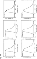
- Fig. 3 shows the electroluminescent (EL) spectrum of the organic EL element EL(1-A), EL(2-A), EL(3-A), EL(4-A), EL(1-B), EL(2-B), EL(3-B), EL(4-B), EL(1-X), EL(2-X), EL(3-X), EL(4-X).
- the EL spectrum was measured at the maximum luminance L max .
- Element Lumines-cence starting voltage Maximum luminance Maximum external quantum efficiency Maximum current efficiency Maximum power efficiency ⁇ EL /nm CIE (x,y) V turn-on N L max /cd m -2 (@V) ⁇ ext.
- the organic EL elements produced by using complexes 1-A, 2-A, 3-A, 4-A, 1-B, 2-B, 3-B, and 4-B exhibit improved organic EL properties in comparison with the organic EL elements produced by using the complexes 1-X, 2-X, 3-X, and 4-X.
- the organoiridium complex of the present invention is suitable as a emitting material of the organic EL element because of high photoluminescence quantum yield in the polymer thin film.
- the present invention is suitable as a yellow to green emitting material.
Landscapes
- Chemical & Material Sciences (AREA)
- Organic Chemistry (AREA)
- Engineering & Computer Science (AREA)
- Materials Engineering (AREA)
- Crystallography & Structural Chemistry (AREA)
- Inorganic Chemistry (AREA)
- Physics & Mathematics (AREA)
- Optics & Photonics (AREA)
- Electroluminescent Light Sources (AREA)
Abstract

Description
- The present invention relates to a technique that provides an organoiridium complex suitable as an organic electroluminescent (EL) element, and particularly relates to an organoiridium complex useful as a green to yellow emitting material.
- Technical development of the organic electroluminescent (EL) element is expected as next-generation displays and lighting. The features have advantages of low energy consumption, being capable of making thinner, excellent response speed, being capable of clear image display in both dark and bright places, and the like.
- The basic structure of the organic EL element is a sandwich-like structure in which an organic compound of sole layer or multiple layers is sandwiched by a pair of electrodes. Specifically, there is proposed an element having a structure which uses, as a main configuration, a sandwich structure of a cathode / electron transport layer / emission layer / positive hole transport layer / anode / glass substrate, and which is obtained by appropriately adding a positive hole (electron) injection layer, buffer layer, interlayer insulating film, and the like in order to further enhance the properties. The emission layer which is a center of the sandwich structure uses various emitting materials, and the properties of the emission layer are required to easily flow electrons and positive holes which are transported from the cathode and anode, to have excellent light emission efficiency, to be durable, and the like.
- Because of those demanded properties, development of phosphorescent materials has been required instead of the fluorescent materials having been conventionally applied as the emitting materials for the organic EL element. Since a generation probability ratio of excited molecule of an excited singlet to that of an excited triplet is 1:3 in the organic EL element, the phosphorescent material which exhibits phosphorescence by transition from the excited triplet state to the ground state is focused on in contrast to the fluorescent material which emits light by transition from the excited singlet to the ground state. Various organometallic complexes have been developed as such phosphorescent materials, and for example, there has been proposed an organometallic complex, as represented by the following Formula, in which a ligand (C-N ligand) having a heterocyclic ring and a C-N structure, and a ligand such as β-diketone are coordinated with a metal atom such as platinum or iridium. Specifically,
PTL 1 discloses an organoiridium complex having a ligand with two benzene rings (diphenyl diketone) as the β-diketone ligand (SO2, etc. in PTL 1). In addition,PTL 2 discloses an organoplatinum complex or the like having a ligand with two butoxy-substituted benzene rings (tetra-butoxydiphenyl diketone) as the β-diketone ligand (PTL 2, Formula [1-1]). The light emission efficiency of the organometallic complexes described in the aforementioned PTLs is enhanced by application of the ligands having benzene ring as the β-diketone ligand.
-
- PTL 1:
Japanese Patent Laid-Open Publication No. 2005-35902 - PTL 2:
Japanese Patent Laid-Open Publication No. 2008-222635 - Incidentally, "current efficiency (cd/A)" and "quantum efficiency (%)" are known as a basis for evaluating the light emission efficiency of the organic EL element. The current efficiency exhibits a luminance (or light strength considering visibility) with respect to an amount of current per unit, whereas the quantum efficiency is a percentage of the number of photons capable of being taken out as light energy with respect to an electric power consumption (the number of the injected carriers). In the quantum efficiency, there can be eliminated a part of consumed power which cannot be emitted as light energy (for example, a part of loss due to resistance), of the consumed power. Therefore, when evaluating the light emission efficiency by the quantum efficiency rather than the current efficiency, it is possible to evaluate the light emission efficiency of the organic EL element as a value close to the actual efficiency. Under these circumstances, when considering the organometallic complexes described in
PTLs - In addition, it is effective that the aforementioned quantum efficiency shows a high value in a polymer (solid) such as a thin film. The reason is that usually an organometallic complex is not introduced in a solution or solvent, but is doped in a polymer thin film and is utilized as a emission layer in implementation to the organic EL element. In this point, many of the organometallic complexes described in
PTLs - Accordingly, the present invention is aimed at providing an organometallic complex that has high quantum efficiency even in a (polymer) thin film as a emitting material for the organic EL element, and particularly provides an organometallic complex which can produce an organic EL element having high quantum efficiency with respect to a green to yellow electroluminescence.
- For solving the aforementioned problems, the present inventors have focused on an organoiridium complex having iridium as a center atom. Although platinum complexes have also been developed as the organometallic complexes as described in
PTL 2, the platinum complex has a high flatness and has an unoccupied ligand in the platinum atom that is the center element, and thus energy loss is easily generated. Specifically, the platinum complex is affected by various interactions including: intermolecular interaction (so-called self-organization) such as association-excimer formation; interaction with a medium such as solvents or matrix (mother materials); furthermore, association with other coexisting molecules; and the like. On the other hand, in the organoiridium complex, since the three ligands have a steric conformation, the aforementioned various interactions as in the platinum complex are not generated, and the energy loss is not easily caused, and thus it is considered that a material having high quantum efficiency is easily obtained. - Moreover, with respect to the quantum efficiency, attention has been focused on a "photoluminescence (PL) quantum yield" of the emitting material which is one of the factors that determines the quantum efficiency. When the quantum efficiency is roughly divided into "external quantum efficiency" and "internal quantum efficiency", this PL quantum yield is, as shown in the following equations, one of the factors that determine the internal quantum efficiency. High internal quantum efficiency is required for the emitting materials, and particularly, influences of "exciton generation efficiency" and "PL quantum yield" are large as the factor that determines the internal quantum efficiency. Among them, since the "exciton generation efficiency" is determined depending on the difference in a fluorescent material and a phosphorescent material, the height of the PL quantum yield is important in order to enhance the internal quantum efficiency. Note that carrier balance in the following equation is a factor determined by combination of the materials and element structure such as film thickness control.
-


- Accordingly, the present inventors have intensively studied organoiridium complexes showing a high photoluminescence (PL) quantum yield particularly in the polymer thin film. In the way of the study, the inventors have focused on organoiridium complexes which generate so-called "rigidchromism" where the emitted light in the polymer thin film is changed to be different from the emitted light in a solvent of solution, and have found that some complexes which generate such a rigidchromism show a high photoluminescence quantum yield in the polymer thin film, and then have completed the present invention. Here, the "chromism" means a phenomenon that optical properties of a substance are changed reversibly by an external stimulation. The "rigidchromism" indicates the case that the external stimulation which induces the chromism depends on the kind of the medium molecule, and the color of the emitted light is changed depending on whether the medium molecule is solution or solid. On the basis of the above studies, the present inventors have completed the present invention as an organoiridium complex which generates the rigidchromism.
- Namely, the present invention relates to an organoiridium complex for an organic electroluminescent element represented by the following Formula; wherein a C-N ligand including two atomic groups (A1, A2), and a β-diketone) ligand in line symmetry having two tert-butyl-substituted phenyl groups are coordinated with an iridium atom.

- The primary feature of the present invention is that, while assuming that the β-diketone as a ligand has a phenyl group and is in line-symmetry, it further has tert-butyl group as a substituent. An organoiridium complex having such a β-diketone) tends to have a high photoluminescence quantum yield. However, even in the organoiridium complex having such a tert-butyl group, when a surrounding medium molecule was a solid polymer thin film, the quantum efficiency was not always to be high. As a result of further study by the present inventors as to the organoiridium complex having a high photoluminescence quantum yield even in the polymer thin film, the present invention has been completed by employing the following structure as the C-N ligand. On the other hand, for the design of the structure of an organometallic complex in the conventional techniques, the C-N ligand may be optionally selected from many mentioned structures as long as the desired luminescent color (red, blue, green, etc.) can be emitted, mainly in consideration of the wavelength sift. Namely, in the conventional technique, only the structure of β-diketone was characterized with almost no limitation of the C-N ligand.
- As explained above, according to the present invention, the aforementioned β-diketone ligand is employed and, at the same time, the C-N ligand is also limited to the ligand having the following structure. When providing the organoiridium complex having a high photoluminescence quantum yield even in the polymer thin film, the present inventors have thought that the reason why the structure of the C-N ligand is to be specified is that the light emitting excited state of the iridium complex having a high photoluminescence quantum yield in the thin film is based on the charge transfer transition from the O-O ligand to the C-N ligand, and the C-N ligand preferably has a structure having a high electron accepting property. Here, when the polarity of the iridium complex is different between ground state and excited state, it is one factor of rigidchromism that the energy level (band gap) ΔE varies by the influences of the surrounding medium molecule. And, when creating the excited state of a charge transfer type by the aforementioned electron accepting C-N ligand, the rigidchromism may be realized. As a result, the present inventors have thought that an organoiridium complex, which makes the photoluminescence quantum yield varying with ΔE in the thin film high, would be available.
- From the above studies, the present inventors have completed the present invention which is an organoiridium complex having a high photoluminescence quantum yield particularly in the thin film by specifying not only the feature of the β-diketone ligand but also the kind of the structure of the C-N ligand. The rigidchromism occurred in the organoiridium complex of the present invention is that in a peak of emission spectrum, a wavelength (λPL) in the polymer thin film shifts more to the short wavelength side, than a wavelength (λPL) in an organic solvent. When the wavelength shift (ΔλPL) due to this rigidchromism is 15 nm or more and 100 nm or less, the organoiridium complex tends to have a particularly high light emission quantum efficiency. Further, the ΔλPL is particularly preferably 25 nm or more and 60 nm or less.
- Hereinafter, the organoiridium complex of the present invention will be explained in detail.
- The organoiridium complex of the present invention is obtained by coordinating the two C-N ligands and the β-diketone with the trivalent iridium atom. The two C-N ligands have the same structure, and the β-diketone has the line-symmetrical structure. The specific structures of the C-N ligand and the β-diketone ligand will be explained below.
- The β-diketone ligand applied to the present invention is the compound having two tert-butyl-substituted phenyl groups represented by the following Formula.

- In the above Formula, R1, R2, and R3 are each tert-butyl group or hydrogen atom. One phenyl group has at least one tert-butyl group, preferably two or more tert-butyl groups. The two tert-butyl groups may bond each other to thereby form a saturated hydrocarbon ring.
- The structure of the particularly preferable β-diketone ligand is shown below. In the following Formula, t-Bu represents tert-butyl group.

- Next, the C-N ligand will be explained. A general formula of the C-N ligand applied to the present invention is represented by the following Formula.

- In the above C-N ligand, the upper-side atomic group A1 is the unsaturated hydrocarbon ring, and is preferably a 6-membered ring. The A1 is preferably a single heterocyclic ring or a single benzene ring, and the heteroatom in the heterocyclic ring is preferably nitrogen. Further, A1 may have any substituent in the side chain, and the substituent is preferably fluorine atom (F), trifluoro (-CF3) group, or cyano (-CN) group.
- Specifically, as the atomic group A1, any one shown in the following Formulae is preferable. In the following Formulae, the bonding site of A1 to A2 is designated by a downward dotted line.

- The atomic group A2 of the C-N ligand in the lower side is preferably a single heterocyclic ring, and the hetero atom is preferably nitrogen. Further, the A2 may have any substituent in the side chain, and the preferred substituent includes fluorine atom (F), trifluoro (-CF3) group, an alkyl group (-R, having 1 or more and 10 or less, preferably 1 or more and 4 or less carbons), an alkoxy group (-OR, having 1 or more and 4 or less carbons). Note that the A2 is also an unsaturated hydrocarbon similar to the A1, and is preferably a 6-memberd ring.
- Specifically, as the atomic group A2, any one shown in the following Formulae is preferable. In the following Formula, the bonding site of A2 to A1 is designated by a downward dotted line.

- The C-N ligand having the aforementioned atomic groups A1 and A2 includes the following compounds, for example.


- The organoiridium complex of the present invention mentioned above has high light emission efficiency, and when 0.05 mmol/g doping is performed in a polymer thin film, the internal quantum efficiency ΦPL is 0.45 or more. Therefore, the organoiridium complex is suitable for implementation to the organic electroluminescent element as the emission layer.
- Furthermore, the organoiridium complex of the present invention tends to show a particularly high photoluminescence quantum yield in the polymer thin film in the range of the emission light color of yellow to green. Specifically, a light emission wavelength (λPL) in the polymer thin film is suitably 510 nm or more and 580 nm or less, particularly suitably 510 nm or more and 550 nm or less.
- The organoiridium complex can be synthesized by reacting an iridium salt and a nitrogen-containing compound that constitutes the C-N ligand with each other by heating to thereby give a precursor, and then by reacting the precursor and a β-diketone compound with each other by heating. Alternatively, the organoiridium complex can also be synthesized by reacting a metal salt with a β-diketone compound, and then by reacting the resultant compound with a nitrogen-containing compound. The heating reaction for obtaining the precursor is preferably carried out at 80°C or more and 130°C or less for 12 hours or more and 24 hours or less, and the heating reaction with the β-diketone is preferably carried out at 60°C or more and 130°C or less for 0.5 hour or more and 12 hours or less. The reactions are preferably carried out in the presence of a solvent. The preferred iridium salt to be used in the aforementioned synthetic reaction is a chloride (IrCl3). Furthermore, a hydrate of the chloride can be used as the form of use.
- When the organoiridium complex mentioned above is applied to the organic EL element, the emission layer can be formed by a method such as spin coating method or vacuum deposition method. An element can be easily and inexpensively formed in the spin coating method.
- The organoiridium complex of the present invention is suitable as a emitting material of the organic EL element because of high photoluminescence quantum yield in the polymer thin film.
-
-
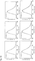
Fig. 1 shows the results of the light emission property of the organoiridium complex according to the embodiment. -
Fig. 2 is a cross-sectional schematic view of the organic EL element produced in the embodiment. -
Fig. 3 shows the results of the light emission property of the organic EL element according to the embodiment. - Hereinafter, there will be explained the preferred embodiments according to the present invention.
- The following organoiridium complexes having the respective ligands were synthesized, and the emission spectrum of the obtained complexes was measured and the photoluminescence quantum yield was evaluated. X is a β-diketone ligand in the conventional example. Each iridium complex was synthesized by reacting an iridium salt and a nitrogen-containing compound to obtain a precursor, and then reacting the precursor and the β-diketone compound.


- First, summary of the synthetic method of each of the aforementioned iridium complexes is explained. Firstly, each of the β-diketone compounds and each of the C-N ligands (1: 2', 6'-difluoro-2,3'-bipyridine), (2: 2-(3,5-bis(trifluoromethyl)phenyl)pyridine), (3: 2-(2,4-bis(trifluoromethyl)phenyl)pyridine) was synthesized. Then, each of the C-N ligands was reacted respectively with iridium chloride to synthesize precursors (1), (2) and (3). Each iridium complex described above was obtained by reacting each precursor with the β-diketone) compound.
- All of the starting materials, the reagents and solvents used for the synthesis were those having commercially available reagent grades without purification. Also with respect to dibenzoylmethane (β-diketone) (X)), the commercially available compound was used as it was for the complex synthesis. The commercially available dehydrated THF was used as the dry THF as it was. In addition, a spherical silica gel (neutral) manufactured by KANTO CHEMICAL CO., INC. was used as a filler to be used for a column chromatography.
- A proton nuclear magnetic resonance (1H NMR) spectrum and a mass analysis (mass (MS) spectrum) were used for identification of the synthesized complexes. Jeol JNM-ECX400 spectrophotometer (400 MHz) or Jeol JNM-ECS400 spectrophotometer (400 MHz) was used for measurement of the 1H NMR spectrum. The MS spectrum was measured by subjecting a sample ionized by an electro-spray ionization method (ESI method), or a matrix-assisted laser desorption ionization method (MALDI method) to the time-of-flight (TOF) type mass spectrometry (ESI-TOF-MS and MALDI-TOF-MS spectrum). Note that, in the MALDI-TOF-MS spectrum, α-cyano-4-hydroxycinnamic acid (CHCA) was used as a matrix. For the ESI-TOF-MS measurement, Jeol JML-T100LP mass spectrometry analyzer was used, and for the MALDI-TOF-MS measurement, Shimadzu-Kratos AXIMA-CFR PLUS TOF Mass mass spectrometry analyzer was used. Elemental analysis was performed by J-Science MICRO CORDER JM10 analysis machine by using acetanilide as a standard substance.
- After
methyl 3,5-di(tert-butyl)benzoate and 3',5'-di(tert-butyl)acetophenone were synthesized from 3,5-di(tert-butyl)benzoic acid, the β-diketone compound (A) was obtained by the synthetic reaction using these two compounds. - A concentrated sulfuric acid (0.9 mL) was dropped onto a mixture of 3,5-di(tert-butyl)benzoic acid (3.00 g, 12.8 mmol) and methanol (9 mL) under a nitrogen atmosphere at 0°C, followed by heating and refluxing the resulting substance for 1 hour with stirring. After being allowed to cool, chloroform (100 mL) was added, and further water (100 mL) was added, with the result that an organic layer was separated by shaking in a separating funnel. After repeating this procedure again, the separated organic layers were combined into one. After further washing the organic layer with a saturated aqueous sodium bicarbonate solution (50 mL) and a saturated saline (50 mL), the organic layer was then dried by addition of an appropriate amount of anhydrous magnesium sulfate. After removal of the magnesium sulfate by filtration,
methyl 3,5-di(tert-butyl)benzoate was obtained by distilling the solvent with an evaporator, and by drying the residue in a desiccator under a reduced pressure. The obtained compound was a white solid, and a yield was 92% (2.92 g, 11.8 mmol). The properties (1H NMR, TOF MS) of the compound thus synthesized were as follows.
1H NMR (CDCl3): δ1.35 (s, 18H), 3.91 (s, 3H), 7.62 (t, J = 2.0 Hz, 1H), 7.89 (d, J = 2.0 Hz, 2H)
MALDI-TOF MS: m/z 249 ([M+H]+)
- 3,5'-di(tert-t-butyl)benzoic acid (3.00 g, 12.8 mmol) was added to a dry tetrahydrofuran (120 mL), and was cooled to 0°C or less with stirring under a nitrogen atmosphere. 3.0 M methyl lithium solution in diethoxymethane (15 mL) was dropped onto the mixture, and after raising the temperature to a room temperature, was stirred for 2 hours. After adding a 6 M hydrochloric acid to the reaction mixture to be acidic, extraction with chloroform (100 mL x 2) was carried out. The obtained organic layers were combined into one, and after washing with water (50 mL x 2), a saturated aqueous sodium bicarbonate solution (50 mL) and a saturated saline (50 mL), an appropriate amount of anhydrous magnesium sulfate was added for drying. After removal of the magnesium sulfate by filtration, 3',5'-di(tert-butyl)acetophenone was obtained by distilling the solvent with an evaporator, and by purifying the residue with a silica gel column chromatography (development solvent; chloroform). The obtained compound was a colorless liquid, and a yield was 75% (2.23 g, 9.60 mmol). The properties of the thus obtained compound were as follows.
1H NMR (CDCl3) δ1.37 (s, 18H), 2.60 (s, 3H), 7.64 (t, J = 1.6 Hz, 1 H), 7.80 (d, J = 1.6 Hz, 2H)
MALDI-TOF MS: m/z 232 (M+)
-
Methyl 3,5-di(tert-butyl)bezoate (2.92 g, 11.8 mmol) and sodium hydride (60% oil dispersion; 1.27 g, 31.8 mmol) were added to a dry THF (23 mL), and were stirred at a room temperature under a nitrogen atmosphere. Then, a solution obtained by dissolving the 3',5'-di(tert-butyl)acetophenone (2.23 g, 9.60 mmol) in a dry THF (23 mL) was dropped onto the resultant substance for 30 minutes. Subsequently, the obtained reaction mixture was stirred for 24 hours at 60°C. After being allowed to cool, and after adding a 1 M hydrochloric acid to be acidic, extraction with chloroform (100 mL x 2) was carried out. The obtained organic layers were combined into one, and after washing with water (50 mL x 2), a saturated aqueous sodium bicarbonate solution (50 mL) and a saturated saline (50 mL), an appropriate amount of anhydrous magnesium sulfate was added for drying. After removal of the magnesium sulfate by filtration, 1,3-bis(3,5-di-(tert-butyl)phenyl) propane-1,3-dion(β-diketone A) was obtained by distilling the solvent with an evaporator, and by purifying the residue with a silica gel column chromatography (development solvent; chloroform). The obtained compound was an amber syrup substance, and a yield was 49% (2.12 g, 4.73 mmol). The properties of the thus obtained compound were as follows.
1H NMR (CDCl3) δ1.38 (s, 36H), 6.78 (s, 1H), 7.63 (t, J = 2.0 Hz, 2H), 7.78 (d, J = 2.0 Hz, 4H), 16.9 (brs, 1 H)
MALDI-TOF MS: m/z 449 ([M+H]+)
- The β-diketone compound (B) was obtained by the synthetic reaction of 1,2,3,4-tetrahydro-1,1,4,4-tetramethylnaphthalene and malonyl chloride.
- 1,2,3,4-tetrahydro-1,1,4,4-tetramethylnaphthalene (5.00 g, 26.6 mmol), malonyl chloride (1.35 g, 9.58 mmol) and aluminum chloride (5.51 g, 41.3 mmol) were added to carbon disulfide (27 mL), and were heated and stirred at 50°C. Next, a cooled 2 mol/L hydrochloric acid (27 mL) was added, and after transferring to a separating funnel, extraction was carried out with chloroform. The organic layer was further washed with water, and after distilling the solvent with an evaporator, a concentrated hydrochloric acid (3.5 mL) and chloroform (35 mL) were added, and were then heated and refluxed for 9 hours. After being allowed to cool, the mixture was transferred to a separatory funnel, and was washed with water and a saturated saline. The solvent was distilled off with a rotary evaporator after drying the organic layer by using an anhydrous magnesium sulfate. The β-diketone (B) was obtained in a yield of 39% (1.66 g, 3.74 mmol) by purifying the residue with a silica gel column chromatography (development solvent; ethyl acetate : hexane = 1:2 (v/v)). The properties of the thus obtained compound were as follows.
1H NMR (CDCl3): δ1.30 (s, 12H), 1.34 (s, 12H), 1.71 (m, 8H), 6.76 (s, 1H), 7.40 (d, J = 8.0 Hz, 2H), 7.68 (dd, J = 8.0 and 2.0 Hz, 2H), 7.94 (d, J = 2.0 Hz, 2H), 16.96 (brs, 1H)
MALDI-TOF MS: m/z 445 ([M+H]+)
- Next, the C-N ligands (1) to (4) were synthesized according to the following manner.
- In accordance with the following formula, a C-N ligand (1) was obtained by reacting 2,6-difluoropyridineboronic acid with 2-bromopyridine. A mixture of 2,6-difluoropyridineboronic acid (2.08 g, 13.1 mmol), 2-bromopyridine (1.34 g, 8.48 mmol), THF (65 mL), water (26 mL), K2CO3 (1.51 g, 10.9 mmol) and Pd(PPh3)4 (0.67 g, 0.580 mmol) was heated and refluxed for 16 hours under a nitrogen atmosphere. After being allowed to cool, the mixture was concentrated to approximately 1/3 in solution volume by a rotary evaporator, and then the obtained mixture was transferred to a separating funnel. After diluting with an appropriate amount of chloroform, the mixture was washed with water and a saturated saline, and the organic layer was dried on anhydrous magnesium sulfate. After removal of the magnesium sulfate by filtration, the solvent of the filtrate was distilled off with a rotary evaporator. The C-N ligand (1) was obtained in a yield of 93% (1:51 g, 7.86 mmol) by purifying the residue with a silica gel chromatography (development solvent; ethyl acetate : hexane = 1:3 (v/v)). The 1H NMR property of the thus synthesized compound was as follows.
1H NMR (CDCl3): 56.93 (dd, J = 3.2, and 8.4 Hz, 1H), 7.20-7.32 (m, 1H), 7.68-7.86 (m, 2H), 8.56-8.73 (m, 2H)
- In accordance with the following formula, a C-N ligand (2) was obtained by reacting 3,5-bis(trifluoromethyl)phenylboronic acid with 2-iodopyridine. A mixture of 3,5-bis(trifluoromethyl)phenylboronic acid (2.00 g, 7.75 mmol), 2-iodopyridine (1.17 g, 5.71 mmol), THF (30 mL), water (10 mL), K2CO3 (4.50 g, 32.6 mmol) and Pd(PPh3)4 (0.261 g, 0.226 mmol) was heated and refluxed for 48 hours under a nitrogen atmosphere. After being allowed to cool, the mixture was concentrated to approximately 1/3 in solution volume by a rotary evaporator, and then the obtained mixture was transferred to a separating funnel. After diluting with an appropriate amount of chloroform, the mixture was washed with water and a saturated saline, and the organic layer was dried on anhydrous magnesium sulfate. After removal of the magnesium sulfate by filtration, the solvent of the filtrate was distilled off with a rotary evaporator. The C-N ligand (2) was obtained in a yield of 51% (0.850 g, 2.92 mmol) by purifying the residue with a silica gel chromatography (development solvent; chloroform). The 1H NMR property of the thus synthesized compound was as follows.
1H NMR (CDCl3): δ7.34-7.38 (m, 1H), 7.81-7.87 (m, 2H), 7.92 (s, 1H), 8.49 (s, 2H), 8.76 (dt, J = 2.2 and 5.0 Hz, 1 H)
- In accordance with the following formula, a C-N ligand (3) was obtained by reacting 2,4-bis(trifluoromethyl)phenylboronic acid with 2-iodopyridine. A mixture of 2,4-bis(trifluoromethyl)phenylboronic acid (2.31 g, 8.96 mmol), 2-iodopyridine (1.16 g, 5.66 mmol), benzene (25 mL), ethanol (10 mL), K2CO3 (7.31 g, 52.9 mmol) and PdCl2(PPh3)2 (0.383 g, 0.546 mmol) was heated and refluxed for 16 hours under a nitrogen atmosphere. After being allowed to cool, the reaction mixture was transferred to a separating funnel. After diluting with an appropriate amount of chloroform, the mixture was washed with water and a saturated saline, and the organic layer was dried on anhydrous magnesium sulfate. After removal of the magnesium sulfate by filtration, the solvent was distilled off with a rotary evaporator. The C-N ligand (3) was obtained in a yield of 59% (0.978 g, 3.36 mmol) by purifying the residue with a silica gel chromatography (development solvent; chloroform). The 1H NMR property of the thus synthesized compound was as follows.
1H NMR (CDCl3): δ7.33 (ddd, J = 7.8, 7.7 and 1.1 Hz, 1H), 7.42 (d, J = 7.8 Hz, 1H), 7.64 (d, J = 7.7 Hz, 1H), 7.76 (ddd, J = 7.7, 7.7 and 1.9 Hz, 1H), 7.86 (d, J = 8.3 Hz, 1H), 8.01 (s, 1H)

- In accordance with the following formula, a C-N ligand (4) was obtained by reacting 2,4-difluoro-3-cyanophenylboronic acid with 2-iodopyridine. A mixture of 2,4-difluoropyridineboronic acid (0.976 g, 5.34 mmol), 2-iodopyridine (0.733 g, 3.58 mmol), benzene (15 mL), ethanol (6 mL), water (15 mL), K2CO3 (4.56 g, 33.0 mmol) and Pd(PPh3)2 Cl2 (0.215 g, 0.306 mmol) was heated and refluxed for 18 hours under a nitrogen atmosphere. After being allowed to cool, the mixture was concentrated to approximately 1/3 in solution volume by a rotary evaporator, and then the obtained mixture was transferred to a separating funnel. After diluting with an appropriate amount of chloroform, the mixture was washed with water and a saturated saline, and the organic layer was dried on anhydrous magnesium sulfate. After removal of the magnesium sulfate by filtration, the solvent of the filtrate was distilled off with a rotary evaporator. The C-N ligand (4) was obtained in a yield of 80% (0.620 g, 2.87 mmol) by purifying the residue with a silica gel chromatography (development solvent; chloroform). The 1H NMR property of the thus synthesized compound was as follows.
1H NMR (CDCl3): δ7.18 (ddd, J = 1.4, 7.8 and 9.2 Hz, 1H), 7.33 (ddd, J = 1.4, 5.0 and 7.3 Hz, 1H), 7.76-7.84 (m, 2H), 7.86 (td, J = 6.4 and 8.7 Hz, 1H), 8.72 (m, 1H)
- Precursor (1) to (3) were obtained by casing each of the thus synthesized C-N ligands and iridium chloride to react with each other.
- In accordance with the following formula, a precursor (1) was obtained by casing the C-N ligand (1) and iridium chloride to react with each other. A mixture of 2',6'-difluoro-2,3'-bipyridine (0.500 g, 2.60 mmol), iridium chloride trihydrate (0.442 g, 1.25 mmol), water (17 mL) and 2-ethoxyethanol (48 mL) was stirred for 12 hours at 100°C. After being allowed to cool, the mixture was concentrated by a rotary evaporator, water (50 mL) was added to the mixture. The resulting precipitant was recovered by suction filtration, and then the precursor (1) was obtained in a yield of 73% (0.580 g, 0.475 mmol) by washing with an appropriate amount of methanol. The thus obtained compound was an insoluble solid. Without further purification, the compound was used for the following synthesis of an iridium complex.

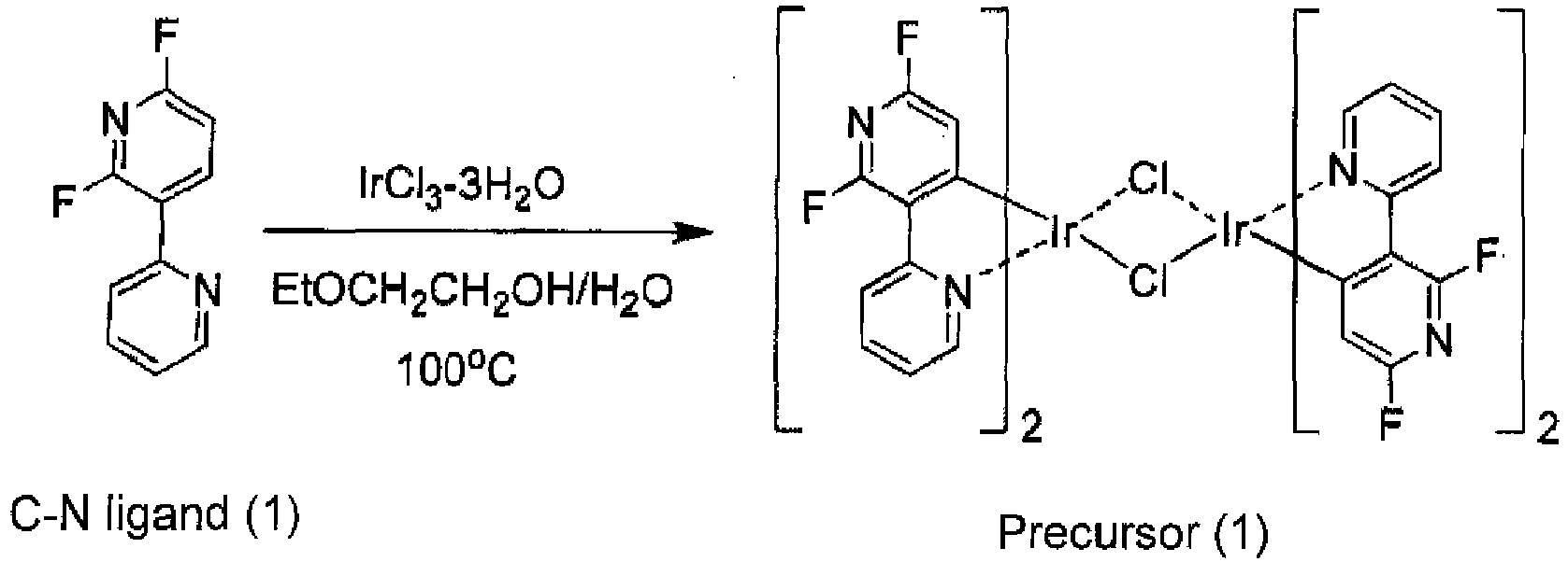
- In accordance with the following formula, a precursor (2) was obtained by casing the C-N ligand (2) and iridium chloride to react with each other. A mixture of 2-(3,5-bis(trifluoromethyl)phenyl)pyridine (0.850 g, 2.92 mmol), iridium chloride trihydrate (0.430 g, 1.22 mmol), water (20 mL) and 2-ethoxyethanol (48 mL) was stirred for 12 hours at 100°C. After being allowed to cool, the mixture was concentrated by a rotary evaporator, water (50 mL) was added to the mixture. The resulting precipitant was recovered by suction filtration, and then the precursor (2) was obtained in a yield of 79% (0.930 g, 0.575 mmol) by washing with an appropriate amount of methanol. The thus obtained compound was an insoluble solid. Without further purification, the compound was used for the following synthesis of an iridium complex.


- In accordance with the following formula, a precursor (3) was obtained by casing the C-N ligand (3) and iridium chloride to react with each other. A mixture of 2-(2,4-bis(trifluoromethyl)phenyl)pyridine (0.431 g, 1.48 mmol), iridium chloride trihydrate (0.264 g, 0.749 mmol), water (10 mL) and 2-ethoxyethanol (28 mL) was stirred for 12 hours at 100°C. After being allowed to cool, the mixture was concentrated by a rotary evaporator, water (30 mL) was added to the mixture. The resulting precipitant was recovered by suction filtration, and then the precursor (3) was obtained in a yield of 55% (0.329 g, 0.204 mmol) by washing with an appropriate amount of methanol. The thus obtained compound was an insoluble solid. Without further purification, the compound was used for the following synthesis of an iridium complex.


- In accordance with the following formula, a precursor (4) was obtained by casing the C-N ligand (4) and iridium chloride to react with each other. A mixture of 2,6-difluoro-3-(pyridine-2-yl)benzonitrile (0.612 g, 2.83 mmol), iridium chloride trihydrate (0.492 g, 1.40 mmol), water (21 mL) and 2-ethoxyethanol (64 mL) was stirred for 25 hours at 100°C. After being allowed to cool, the mixture was concentrated by a rotary evaporator, water (50 mL) was added to the mixture. The resulting precipitant was recovered by suction filtration, and then the precursor (4) was obtained in a yield of 83% (0.762 g, 0.579 mmol) by washing with an appropriate amount of methanol. The thus obtained compound was an insoluble solid. Without further purification, the compound was used for the following synthesis of an iridium complex.


- The thus synthesized precursors (1) to (4) and β-diketones (A), (B), and (X) were reacted with each other respectively to give respective iridium complexes.
- In accordance with the following formula, the iridium complex 1-A was obtained by reacting the precursor (1) and the β-diketone (A) with each other.

- The precursor (1) (0.244 g, 0.200 mmol), 1,3-bis(3,5-di(tert-butyl)phenyl)propane-1,3-dione (β-diketone (A)), (0.131 g, 0.292 mmol) and sodium carbonate (1.90 g, 17.9 mmol) was added to 2-ethoxyethanol (50 mL), and the resulting mixture was stirred for 30 minutes at 80°C under a nitrogen atmosphere. After being allowed to cool, the solvent was distilled off by a rotary evaporator, and then chloroform was added to the residue. The obtained mixed solution was washed with water and a saturated saline, and was then dried by adding an appropriate amount of anhydrous sodium sulfate. After removal of the sodium sulfate by filtration, the solvent of the filtrate was distilled off with a rotary evaporator. The iridium complex 1-A was obtained in a yield of 25% (73.5 mg, 0.0719 mmol) by purifying the obtained residue with a silica gel column chromatography (development solvent; methylene chloride), and by further performing recrystallization using acetonitrile. The properties of the thus synthesized compound were as follows.
1H NMR (CDCl3): δ1.26 (s, 36H), 5.81 (t, J = 1.8 Hz, 2H), 6.58 (s, 1H), 7.19-7.22 (m, 2H), 7.53 (m, 6H), 7.85-7.89 (m, 2H), 8.29 (d, J = 7.6 Hz, 2H), 8.57 (dd, J = 0.80 and 6.0 Hz, 2H)
ESI-TOF MS: m/z 1045 ([M+Na]+)
Anal. Calcd for C51H53F4IrN4O2: C, 59.92; H, 5.23; 5.48. Found: C, 60.10; H, 5.03; 5.50 - In accordance with the following formula, the iridium complex 1-B was obtained by reacting the precursor (1) and the β-diketone (B) with each other.


- The precursor (1) (0.246 g, 0.201 mmol), β-diketone (B), (0.129 g, 0.290 mmol) and sodium carbonate (1.90 g, 17.9 mmol) was added to 2-ethoxyethanol (50 mL), and the resulting mixture was stirred for 30 minutes at 80°C under a nitrogen atmosphere. After being allowed to cool, the solvent was distilled off by a rotary evaporator, and then chloroform was added to the residue. The obtained mixed solution was washed with water and a saturated saline, and was then dried by adding an appropriate amount of anhydrous sodium sulfate. After removal of the sodium sulfate by filtration, the solvent of the filtrate was distilled off with a rotary evaporator. The iridium complex 1-B was obtained in a yield of 25% (75.1 mg, 0.0738 mmol) by purifying the obtained residue with a silica gel column chromatography (development solvent; methylene chloride), and by further performing recrystallization using methanol. The properties of the thus synthesized compound were as follows.
1H NMR (CDCl3): δ1.23 (s, 12H), 1.25(s, 12H), 1.66 (s, 8H), 5.76 (s, 2H), 6.58(s, 1H), 7.17-7.21 (m, 2H), 7.29 (d, J = 8.0 Hz, 2H), 7.49-7.52 (m, 2H), 7.71 (d, J = 2.0 Hz, 2H), 7.83-7.87 (m, 2H), 8.27 (d, J = 8.8 Hz, 2H), 8.53 (d, J = 6.0 Hz, 2H)
ESI-TOF MS: m/z 1041 ([M+Na]+)
Anal. Calcd for C51H49F4IrN4O2: C, 60.16; H, 4.85; 5.50. Found: C, 60.12; H, 4.61; 5.45 - In accordance with the following formula, the iridium complex 1-X was obtained by reacting the precursor (1) and the β-diketone (X) with each other.

- The precursor (1) (0.500 g, 0.410 mmol), β-diketone (X), (0.435 g, 1.94 mmol) and sodium carbonate (0.389 g, 3.67 mmol) was added to 2-ethoxyethanol (77 mL), and the resulting mixture was stirred for 2 hours at 105°C under a nitrogen atmosphere. After being allowed to cool, the solvent was distilled off by a rotary evaporator, and then chloroform was added to the residue. The obtained mixed solution was washed with water and a saturated saline, and was then dried by adding an appropriate amount of anhydrous sodium sulfate. After removal of the sodium sulfate by filtration, the solvent of the filtrate was distilled off with a rotary evaporator. The iridium complex 1-X was obtained in a yield of 38% (250 mg, 0.313 mmol) by purifying the obtained residue with a silica gel column chromatography (development solvent; methylene chloride), and by further performing recrystallization using methanol. The properties of the thus synthesized compound were as follows.
1H NMR (CDCl3): δ5.75 (s, 2H), 6.66 (s, 1H), 7.23-7.25 (m, 2H), 7.35 (t, J = 7.8 Hz, 4H), 7.45-7.47 (m, 2H), 7.77 (dd, J = 1.2 and 7.8 Hz,4H), 7.88 (t, J = 7.8 Hz, 2H), 8.29 (d, J = 8.0 Hz, 2H), 8.52 (d, J = 6.0 Hz, 2H)
ESI-TOF MS: m/z 821 ([M+Na]+)
Anal. Calcd for C35H21F4IrN4O2: C, 52.69; H, 2.65; 7.02. Found: C, 52.92; H, 2.73; 7.01 - In accordance with the following formula, the iridium complex 2-A was obtained by reacting the precursor (2) and the β-diketone (A) with each other.

- The precursor (2) (0.245 g, 0.152 mmol), 1,3-bis(3,5-di(tert-butyl)phenyl)propane-1,3-dione (β-diketone (A)), (0.129 g, 0.288 mmol) and sodium carbonate (1.90 g, 17.9 mmol) was added to 2-ethoxyethanol (50 mL), and the resulting mixture was stirred for 2 hours at 100°C under a nitrogen atmosphere. After being allowed to cool, the solvent was distilled off by a rotary evaporator, and then chloroform was added to the residue. The obtained mixed solution was washed with water and a saturated saline, and was then dried by adding an appropriate amount of anhydrous sodium sulfate. After removal of the sodium sulfate by filtration, the solvent of the filtrate was distilled off with a rotary evaporator. The iridium complex 2-A was obtained in a yield of 5.8% (20.3 mg, 0.0166 mmol) by purifying the obtained residue with a silica gel column chromatography (development solvent; chloroform : hexane = 1:1 (v/v)), and by further performing recrystallization using methanol. The properties of the thus synthesized compound were as follows.
1H NMR (CDCl3): δ1.24 (s, 36H), 6.34 (s, 1H), 6.94-6.97 (m, 2H), 7.30 (d, J = 1.6 Hz, 4H), 7.48 (t, J = 1.6 Hz, 2H), 7.55 (brs, 2H), 7.78 (dt, J = 1.6 and 7.8 Hz, 2H), 8.05 (d, J = 7.6 Hz, 2H), 8.16 (brs, 2H), 8.27 (d, J = 6.0 Hz, 2H)
ESI-TOF MS: m/z 1243 ([M+Na]+)
Anal. Calcd for C57H55F12IrN2O2: C, 56.10; H, 4.54; 2.30. Found: C, 55.93; H, 4.49; 2.26 - In accordance with the following formula, the iridium complex 2-B was obtained by reacting the precursor (2) and the β-diketone (B) with each other.

- The precursor (2) (0.154 g, 0.0953 mmol), β-diketone (B), (0.200 g, 0.450 mmol) and sodium carbonate (0.0900 g, 0.849 mmol) was added to 2-ethoxyethanol (18 mL), and the resulting mixture was stirred for 3 hours at 105°C under a nitrogen atmosphere. After being allowed to cool, the solvent was distilled off by a rotary evaporator, and then chloroform was added to the residue. The obtained mixed solution was washed with water and a saturated saline, and was then dried by adding an appropriate amount of anhydrous sodium sulfate. After removal of the sodium sulfate by filtration, the solvent of the filtrate was distilled off with a rotary evaporator. The iridium complex 2-B was obtained in a yield of 39% (90.0 mg, 0.0740 mmol) by purifying the obtained residue with a silica gel column chromatography (development solvent; chloroform), and by further performing recrystallization using methanol. The properties of the thus synthesized compound were as follows.
1H NMR (CDCl3): δ1.16 (s, 12H), 1.23(s, 12H), 1.64 (s, 8H), 6.32 (s, 1H), 6.91-6.95 (m, 2H), 7.22 (d, J = 7.8 Hz, 2H), 7.30 (dd, J = 2.0 and 7.8 Hz, 2H), 7.43 (d, J = 2.0 Hz, 2H), 7.55 (s, 2H), 7.73-7.78 (m, 2H), 8.01 (d, J = 8.0 Hz, 2H), 8.16 (s, 2H), 8.22 (d, J = 6.0 Hz, 2H)
ESI-TOF MS: m/z 1239 ([M+Na]+)
Anal. Calcd for C57H51F12IrN2O2: C, 56.29; H, 4.23; 2.30. Found: C, 56.60; H, 4.40; 2.26 - In accordance with the following formula, the iridium complex 2-X was obtained by reacting the precursor (2) and the β-diketone (X) with each other.

- The precursor (2) (0.331 g, 0.205 mmol), β-diketone (X), (0.220 g, 0.981 mmol) and sodium carbonate (0.195 g, 1.84 mmol) was added to 2-ethoxyethanol (39 mL), and the resulting mixture was stirred for 3 hours at 105°C under a nitrogen atmosphere. After being allowed to cool, the solvent was distilled off by a rotary evaporator, and then chloroform was added to the residue. The obtained mixed solution was washed with water and a saturated saline, and was then dried by adding an appropriate amount of anhydrous sodium sulfate. After removal of the sodium sulfate by filtration, the solvent of the filtrate was distilled off with a rotary evaporator. The iridium complex 2-X was obtained in a yield of 30% (120 mg, 0.121 mmol) by purifying the obtained residue with a silica gel column chromatography (development solvent; chloroform), and by further performing recrystallization using methanol. The properties of the thus synthesized compound were as follows.
1H NMR (CDCl3): δ6.43 (s, 1H), 6.94-6.98 (m, 2H), 7.29 (t, J = 7.8 Hz, 4H), 7.41 (t, J = 7.8 Hz, 2H), 7.55-7.57 (m, 6H), 7.74-7.78 (m, 2H), 8.00 (d, J = 8.4 Hz, 2H), 8.13 (s, 2H), 8.21 (d, J = 6.0 Hz, 2H)
ESI-TOF MS: m/z 1019 ([M+Na]+)
Anal. Calcd for C41H23F12IrN2O2•H2O: C, 48.57; H, 2.49; 2.76. Found: C, 48.76; H, 2.60; 2.67 - In accordance with the following formula, the iridium complex 3-A was obtained by reacting the precursor (3) and the β-diketone (A) with each other.

- The precursor (3) (0.240 g, 0.149 mmol), 1,3-bis(3,5-di(tert-butyl)phenyl)propane-1,3-dione (β-diketone (A)), (0.129 g, 0.288 mmol) and sodium carbonate (1.91 g, 18.1 mmol) was added to 2-ethoxyethanol (50 mL), and the resulting mixture was stirred for 2 hours at 100°C under a nitrogen atmosphere. After being allowed to cool, the solvent was distilled off by a rotary evaporator, and then chloroform was added to the residue. The obtained mixed solution was washed with water and a saturated saline, and was then dried by adding an appropriate amount of anhydrous sodium sulfate. After removal of the sodium sulfate by filtration, the solvent of the filtrate was distilled off with a rotary evaporator. The iridium complex 3-A was obtained in a yield of 44% (154 mg, 0.126 mmol) by purifying the obtained residue with a silica gel column chromatography (development solvent; chloroform : hexane = 1:1 (v/v)), and by further performing recrystallization using methanol. The properties of the thus synthesized compound were as follows.
1H NMR (CDCl3): δ1.25 (s, 36H), 6.53 (s, 1H), 6.70 (s, 2H), 7.20-7.24 (m, 2H), 7.44 (d, J = 2.0 Hz, 4H), 7.50 (t, J = 2.0 Hz, 2H), 7.54 (s, 2H), 7.86-7.91 (m, 2H), 8.44 (d, J = 8.0 Hz, 2H), 8.67 (dd, J = 1.4 and 5.8 Hz, 2H)
ESI-TOF MS: m/z 1243 ([M+Na]+)
Anal. Calcd for C57H55F12IrN2O2: C, 56.10; H, 4.54; 2.30. Found: C, 56.27; H, 4.74; 2.41 - In accordance with the following formula, the iridium complex 3-B was obtained by reacting the precursor (3) and the β-diketone (B) with each other.

- The precursor (3) (0.241 g, 0.149 mmol), β-diketone (B), (0.129 g, 0.290 mmol) and sodium carbonate (1.90 g, 18.0 mmol) was added to 2-ethoxyethanol (50 mL), and the resulting mixture was stirred for 2 hours at 100°C under a nitrogen atmosphere. After being allowed to cool, the solvent was distilled off by a rotary evaporator, and then chloroform was added to the residue. The obtained mixed solution was washed with water and a saturated saline, and was then dried by adding an appropriate amount of anhydrous sodium sulfate. After removal of the sodium sulfate by filtration, the solvent of the filtrate was distilled off with a rotary evaporator. The iridium complex 2-B was obtained in a yield of 17% (59.7 mg, 0.0491 mmol) by purifying the obtained residue with a silica gel column chromatography (development solvent; chloroform : hexane = 1:1 (v/v)), and by further performing recrystallization using methanol. The properties of the thus synthesized compound were as follows.
1H NMR (CDCl3): δ1.16 (s, 6H), 1.18(s, 6H), 1.22 (s, 6H), 1.23 (s, 6H), 1.64 (s, 8H), 6.52 (s, 1H), 6.64 (s, 2H), 7.20 (t, J = 6.0 Hz, 2H), 7.27 (d, J = 7.8 Hz, 2H), 7.43 (dd, J = 2.0 and 7.8 Hz, 2H), 7.53 (s, 2H), 7.61 (d, J = 2.0 Hz, 2H), 7.83-7.88 (m, 2H), 8.41 (d, J = 8.0 Hz, 2H), 8.63 (d, J = 6.0 Hz, 2H)
ESI-TOF MS: m/z 1239 ([M+Na]+)
Anal. Calcd for C57H51F12IrN2O2: C, 56.29; H, 4.23; 2.30. Found: C, 56.30; H, 4.05; 2.28 - In accordance with the following formula, the iridium complex 3-X was obtained by reacting the precursor (3) and the β-diketone (X) with each other.

- The precursor (3) (0.200 g, 0.124 mmol), β-diketone (X), (0.128 g, 0.571 mmol) and sodium carbonate (0.115 g, 1.09 mmol) was added to 2-ethoxyethanol (23 mL), and the resulting mixture was stirred for 3 hours at 105°C under a nitrogen atmosphere. After being allowed to cool, the solvent was distilled off by a rotary evaporator, and then chloroform was added to the residue. The obtained mixed solution was washed with water and a saturated saline, and was then dried by adding an appropriate amount of anhydrous sodium sulfate. After removal of the sodium sulfate by filtration, the solvent of the filtrate was distilled off with a rotary evaporator. The iridium complex 3-X was obtained in a yield of 10% (25.0 mg, 0.0251 mmol) by purifying the obtained residue with a silica gel column chromatography (development solvent; chloroform), and by further performing recrystallization using methanol. The properties of the thus synthesized compound were as follows.
1H NMR (CDCl3): δ6.60 (s, 2H), 6.61 (s, 1H), 7.21-7.24 (m, 2H), 7.32 (t, J = 7.4 Hz, 4H), 7.44 (t, J = 7.4 Hz, 2H), 7.54 (s, 2H), 7.72 (d, J = 7.4 Hz, 4H), 7.85-7.90 (m, 2H), 8.41 (d, J = 8.8 Hz, 2H), 8.64 (dd, J = 0.8 and 5.8 Hz, 2H)
ESI-TOF MS: m/z 1019 ([M+Na]+)
Anal. Calcd for C41H23F12IrN2O2: C, 49.45; H, 2.33; 2.81. Found: C, 49.60; H, 2.70; 2.70 - In accordance with the following formula, the iridium complex 4-Awas obtained by reacting the precursor (4) and the β-diketone (A) with each other.


- The precursor (4) (0.243 g, 0.185 mmol), 1,3-bis(3,5-di(tert-butyl)phenyl)propane-1,3-dione (β-diketone (A)), (0.133 g, 0.296 mmol) and sodium carbonate (1.90 g, 17.9 mmol) was added to 2-ethoxyethanol (50 mL), and the resulting mixture was stirred for 2 hours at 100°C under a nitrogen atmosphere. After being allowed to cool, the solvent was distilled off by a rotary evaporator, and then ethyl acetate was added to the residue. The obtained mixed solution was washed with water and a saturated saline, and was then dried by adding an appropriate amount of anhydrous magnesium sulfate. After removal of the magnesium sulfate by filtration, the solvent of the filtrate was distilled off with a rotary evaporator. The iridium complex 4-A was obtained in a yield of 12% (00.459 g, 0.0429 mmol) by purifying the obtained residue with a silica gel column chromatography (development solvent; chloroform), and by further performing recrystallization using methanol. The properties of the thus synthesized compound were as follows.
1H NMR (CDCl3): δ1.26 (s, 36H), 5.98 (d, J = 8.6 Hz, 2H), 6.56 (s, 1H), 7.22 (td, J = 1.4 and 5.9 Hz, 2H), 7.49 (d, J = 1.8 Hz, 4H), 7.54 (t, J = 1.8 Hz, 2H), 7.90 (td, J = 1.4 and 8.2 Hz, 2H), 8.32 (d, J = 8.2 Hz, 2H), 8.55 (dd, J = 1.4 and 5.9 Hz, 2H)
ESI-TOF MS: m/z 1093 ([M+Na]+)
Anal. Calcd for C55H53F4IrN4O2: C, 61.72; H, 4.99; N, 5.23. Found: C, 61.72; H, 5.03; N, 5.23 - In accordance with the following formula, the iridium complex 4-B was obtained by reacting the precursor (4) and the β-diketone (B) with each other.

- The precursor (4) (0.106 g, 0.0805 mmol), β-diketone (B), (0.0884 g, 0.199 mmol) and sodium carbonate (0.0531 g, 0.501 mmol) was added to 2-ethoxyethanol (25 mL), and the resulting mixture was stirred for 1 hour and 30 minutes at 40°C under a nitrogen atmosphere. After being allowed to cool, the solvent was distilled off by a rotary evaporator, and then methylene chloride was added to the residue. The obtained mixed solution was washed with water and a saturated saline, and was then dried by adding an appropriate amount of anhydrous magnesium sulfate. After removal of the magnesium sulfate by filtration, the solvent of the filtrate was distilled off with a rotary evaporator. The iridium complex 4-B was obtained in a yield of 22% (0.0378 g, 0.0355 mmol) by purifying the obtained residue with a silica gel column chromatography (development solvent; methylene chloride), and by further performing recrystallization using methanol. The properties of the thus synthesized compound were as follows.
1H NMR (CDCl3): δ1.24 (m, 24H), 1.66 (m, 8H), 5.92 (d, J = 8.6 Hz, 2H), 6.58 (s, 1H), 7.21-7.24 (m, 2H), 7.29 (d, J = 8.6 Hz, 2H), 7.48 (dd, J = 1.8 and 8.6 Hz, 2H), 7.69 (d, J = 1.8 Hz, 2H), 7.86-7.90 (m, 2H), 8.30 (d, J = 8.6 Hz, 2H), 8.50 (dd, J = 1.4 and 5.9 Hz, 2H)
ESI-TOF MS: m/z 1089 ([M+Na]+)
Anal. Calcd for C55H49F4IrN4O2: C, 61.96; H, 4.63; N, 5.25. Found: C, 61.94; H, 4.59; N, 5.25 - In accordance with the following formula, the iridium complex 4-X was obtained by reacting the precursor (4) and the β-diketone) (X) with each other.


- The precursor (4) (0.0980 g, 0.0745 mmol), β-diketone (X), (0.0496 g, 0.221 mmol) and sodium carbonate (0.0650 g, 0.613 mmol) was added to 2-ethoxyethanol (7 mL), and the resulting mixture was stirred for 30 minutes at 40°C under a nitrogen atmosphere. After being allowed to cool, the solvent was distilled off by a rotary evaporator, and then methylene chloride was added to the residue. The obtained mixed solution was washed with water and a saturated saline, and was then dried by adding an appropriate amount of anhydrous magnesium sulfate. After removal of the magnesium sulfate by filtration, the solvent of the filtrate was distilled off with a rotary evaporator. The iridium complex 4-X was obtained in a yield of 21% (0.0254 g, 0.0300 mmol) by purifying the obtained residue with a silica gel column chromatography (development solvent; methylene chloride), and by further performing recrystallization using methanol. The properties of the thus synthesized compound were as follows.
1H NMR (CDCl3): δ5.91 (d, J = 8.8 Hz, 2H), 6.65 (s, 1H), 7.26-7.28 (m, 2H), 7.35 (t, J = 7.7 Hz, 4H), 7.45-7.49 (m, 2H), 7.75-7.77 (m, 4H), 7.90 (td, J = 1.4 and 8.4 Hz, 2H), 8.32 (d, J = 8.4 Hz, 2H), 8.49 (dd, J = 1.4 and 5.6 Hz, 2H)
ESI-TOF MS: m/z 869 ([M+Na]+)
Anal. Calcd for C39H21F4IrN4O2: C, 55.38; H, 2.50; N, 6.62. Found: C, 55.38; H, 2.74; N, 6.74 - The photoluminescence (PL) spectrum and the PL quantum yield ΦPL of each iridium complex obtained above were measured. Fluorolog-3 spectrometer manufactured by HORIBA, Ltd. was used for measuring the PL spectrum. C9920-12 Quantum yield measuring machine manufactured by HAMAMATSU Photonics K.K. was used for measuring the PL quantum yield. The evaluation of these PL spectrum and PL quantum yield were conducted in a polymer thin film (polymethyl methacrylate, PMMA), as medium. Note that the solution sample sealed with argon gas was measured as a deoxidized solution, and the polymer thin film sample was measured under a nitrogen atmosphere. The polymer thin film sample was measured by 0.05 mmol/g (4 wt%) doping of each iridium complex into PMMA. The results are shown in the following Table.
[Table 1] Wavelength λ PL (nm) PL Quantum yield Φ PL 1-A 537 0.58 2-A 545 0.52 3-A 545 0.49 4-A 543 0.45 1-B 537 0.62 2-B 548 0.47 3-B 548 0.68 4-B 537 0.53 1-X 550 0.23 2-X 561 0.17 - From the above Table, the iridium complexes having the tert-butyl-substituted phenyl group as the β-diketone (1-A, 2-A, 3-A, 4-A, 1-B, 2-B, 3-B, 4-B) showed photoluminescence quantum yields higher than 0.45 in the polymer thin film.
- Next, with respect to the iridium complexes 1-A, 2-A, 1-B, 2-B, the PL spectrum and PL quantum yield were evaluated in an organic solvent (dichloromethane (CH2Cl2)), as medium. The results are shown in the following Table and in
Fig. 1 . In the following Table, the results in the polymer thin film are shown together, and also calculated values of difference (wavelength shift ΔλPL) between the position of wavelength peak in the organic solvent and the position of wavelength peak in the polymer thin film are shown.[Table 2] In organic solvent In polymer thin film Wavelength shift λ PL (nm) Φ PL λ PL (nm) Φ PL Δ λ PL 1-A 573 0.19 537 0.58 36 2-A 595 0.11 545 0.52 50 1-B 567 0.28 537 0.62 30 2-B 596 0.18 548 0.47 48 - From the above Table and
Fig. 1 , with respect to the iridium complexes having the tert-butyl-substituted phenyl group as the λ-diketone) (1-A, 2-A, 1-B, 2-B), the rigidchromism was observed where the position of the wavelength peak in the polymer thin film shifted to the short wavelength side relative to the wavelength peak in an organic solvent. In the viewpoint of luminescent color, the light emission wavelength of yellowish green to orange in the organic solvent changed to the light emission wavelength of green to yellow in the polymer thin film. - From the aforementioned results, it has been found that the iridium complexes having the tert-butyl-substituted phenyl group as the λ-diketone had the PL quantum yield ΦPL of 0.45 or more when doping to the polymer thin film at a dose of 0.05 mmol, and showed the rigidchromism where the light emission wavelength in the polymer thin film shifted to the short wavelength side relative to the light emission wavelength in an organic solvent.
- The iridium complexes were used to produce the organic EL element (1) shown in
Fig. 2 in the following procedures, and its properties were evaluated. - An anode (2) was prepared by subjecting an ITO-glass substrate (manufactured by SANYO Vacuum Industries Co., Ltd., ITO, film thickness 150 nm) to patterning treatment and then by performing washing. Next, the ITO thin film was surface-treated by ozone. After the surface treatment, a hole injection layer (5) having a thickness of 40 nm was formed by rapid film formation of a hole injection material on the ITO film through the use of the spin coating method, and by baking at 120°C for 1 hour. An electrically conductive polymer (P VP CH8000 manufactured by Heraeus Clevios) containing PEDOT and PSS was used as the hole injection material.
- An ink Ink(1-A) for the emission layer was prepared by dissolution of poly(9-vinylcarbasol) (PVCz, manufactured by Sigma-Aldrich, Number average molecular weight Mn, 25000-50000, purified by re-precipitating from THF-methanol), 2-(4-biphenilyl)-5-(4-tert-butylphenyl)-1,3,4-oxadiazole (PBD) and the iridium complex 1-A in a dehydrated toluene, and by filtration with a membrane filter (0.2 µm Millex-FG manufactured by Merck Millipore Corporation). The concentrations of the PBD and the iridium complex to be doped to 1 g of PVCz were 850 µmol and 98 µmol, respectively, and 0.7 ml of the toluene was used to 10 mg of PVCz as a solvent for the ink. Through the use of the obtained ink (1-A) for the emission layer, a
emission layer 4 having a thickness of 80 nm was formed on the hole injection layer (5) by film formation using the spin coating method, and then by baking at 120°C for 1 hour. - A thin film of cesium fluoride (electron injection layer (6),
thickness 1 nm) as the electron-injecting material was formed by the vacuum deposition, through the use of a shadow mask, and then, a thin film of aluminum (cathode (3), thickness 250 nm) was produced. At this time, the electron injection layer (6) and the cathode (3) were produced so that the area of the light-emitting portion was 10 mm2 (2 mm x 5 mm). In this way, the organic EL element EL(1-A) was completed. - An ink Ink (2-A) for the emission layer was prepared by using the iridium complex 2-A instead of the iridium complex 1-A. An organic EL element EL(2-A) was obtained in the similar way to the above procedures except that the ink Ink (2-A) was used for the emission layer. The organic EL elements EL(3-A), EL(4-A), EL(1-B), EL(2-B), EL(3-B), EL(4-B), EL(1-X), EL(2-X), EL(3-X), EL(4-X) were also produced by using the complexes 3-A, 4-A, 1-B, 2-B, 3-B, 4-B, 1-X, 2-X, 3-X, 4-X instead of the complex 1-A.
- Samples for evaluating the organic EL properties were produced with the organic EL element obtained by the above steps sealed into a cavity glass by using an ultraviolet curable resin.
- The organic EL element properties such as EL spectrum, maximum luminance Lmax (cd/m2), maximum external quantum efficiency ηext.max (%), and CIE standard colorimetric system (x,y) were measured by a luminance goniophotometer (C-9920-11, manufactured by HAMAMATSU Photonics K.K.).
- Table 2 shows the results of the peak wavelength λEL (nm), the maximum luminance Lmax (cd/m2), the maximum external quantum efficiency ηnext.max (%), the maximum current efficiency ηj,max (cd/A), the maximum power efficiency ηp,max (lm/W), and CIE standard colorimetric system (x,y). The Lmax and ηext,max are shown along with the applied voltage (V) at the time of measurement in brackets. Note that the luminescence starting voltage Vturn-on represents the voltage at which the luminance reaches 1 cd/m2.
- Furthermore,
Fig. 3 shows the electroluminescent (EL) spectrum of the organic EL element EL(1-A), EL(2-A), EL(3-A), EL(4-A), EL(1-B), EL(2-B), EL(3-B), EL(4-B), EL(1-X), EL(2-X), EL(3-X), EL(4-X). The EL spectrum was measured at the maximum luminance Lmax.[Table 3] Element Lumines-cence starting voltage Maximum luminance Maximum external quantum efficiency Maximum current efficiency Maximum power efficiency λEL /nm CIE (x,y) Vturn-on N Lmax /cd m-2 (@V) ηext. max /% (@V) ηj,max /cd A-1 (@V) ηp,max /lm W-1 (@V) EL (1-A) 4.0 6200 (14.0) 3.0 (8.5) 9.5 (8.5) 4.1 (7.0) 550 (0.43,0.54) EL (1-B) 4.5 4500 (15.0) 1.8 (8.0) 5.8 (6.5) 3.8 (4.5) 539 (0.42,0.54) EL (1-X) 5.0 2900 (15.0) 1.3 (9.5) 4.0 (9.5) 1.2 (7.0) 564 (0.45,0.53) EL (2-A) 4.0 4900 (14.0) 1.7 (9.5) 5.1 (9.5) 1.8 (8.0) 555 (0.44,0.52) EL (2-B) 4.5 3200 (15.5) 1.5 (9.5) 4.3 (11.0) 1.4 (9.5) 555 (0.44,0.52) EL (2-X) 5.5 1500 (15.0) 0.51 (9.0) 1.4 (8.5) 0.58 (7.0) 568 (0.48,0.50) EL (3-A) 6.0 2700 (17.0) 1.1 (11.5) 3.7 (11.5) 1.1 (10.0) 545 (0.46,0.53) EL (3-B) 5.0 3700 (15.5) 1.2 (10.0) 4.1 (11.0) 1.2 (10.0) 543 (0.46,0.53) EL (3-X) 8.5 1000 (18.0) 0.37 (12.5) 1.3 (12.5) 0.31 (12.5) 545 (0.46,0.53) EL (4-A) 4.0 8300 (15.5) 2.9 (10.5) 9.4 (9.5) 3.1 (9.5) 549 (0.42,0.54) EL (4-B) 4.0 11000 (15.0) 2.9 (10.0) 9.0 (10.0) 2.8 (10.0) 551 (0.41,0.54) EL (4-X) 3.5 4400 (15.5) 1.1 (11.0) 3.1 (11.0) 0.98 (9.0) 569 (0.45,0.52) - From the above results, the organic EL elements produced by using complexes 1-A, 2-A, 3-A, 4-A, 1-B, 2-B, 3-B, and 4-B exhibit improved organic EL properties in comparison with the organic EL elements produced by using the complexes 1-X, 2-X, 3-X, and 4-X.
- The organoiridium complex of the present invention is suitable as a emitting material of the organic EL element because of high photoluminescence quantum yield in the polymer thin film. Particularly, the present invention is suitable as a yellow to green emitting material.
Claims (9)
- An organoiridium complex for an organic electroluminescent element represented by a following Formula, wherein a C-N ligand comprising two atomic groups (A1, A2), and a β-diketone) ligand in line symmetry having two tert-butyl-substituted phenyl groups are coordinated with an iridium atom.

- The organoiridium complex according to claim 1, whereinthe η-diketone ligand is any of substituents represented by the following Formula.


- The organoiridium complex according to claim 1 or 2, wherein the A2 is a single heterocyclic ring.
- The organoiridium complex according to any of claims 1 to 3, wherein the A1 is a single benzene ring or a single heterocyclic ring.
- The organoiridium complex according to any of claims 1 to 4, wherein the A1 has a fluorine atom (F), a trifluoro (-CF3) group, or a cyano (-CN) group as a side chain of the unsaturated hydrocarbon ring.
- The organoiridium complex according to any of claims 1 to 5, wherein the A2 has a fluorine atom (F), a trifluoro (-CF3) group, an alkyl group (-R), or an alkoxy group (-OR) as a side chain of the unsaturated hydrocarbon ring.
- The organoiridium complex according to any of claims 1 to 6, wherein a PL quantum yield ΦPL when 0.05 mmol/g doping is performed in a polymer thin film is 0.45 or more.
- The organoiridium complex according to any of claims 1 to 7, wherein the light emission wavelength (λPL) in the polymer thin film is 510 nm or more and 580 nm or less.
- An organic electroluminescent element having a emission layer including the organoiridium complex according to any of claims 1 to 8.
Applications Claiming Priority (2)
| Application Number | Priority Date | Filing Date | Title |
|---|---|---|---|
| JP2014173756 | 2014-08-28 | ||
| PCT/JP2015/073939 WO2016031840A1 (en) | 2014-08-28 | 2015-08-26 | Organic iridium complex for organic electroluminescent elements |
Publications (3)
| Publication Number | Publication Date |
|---|---|
| EP3187503A1 true EP3187503A1 (en) | 2017-07-05 |
| EP3187503A4 EP3187503A4 (en) | 2018-02-28 |
| EP3187503B1 EP3187503B1 (en) | 2019-03-27 |
Family
ID=55399726
Family Applications (1)
| Application Number | Title | Priority Date | Filing Date |
|---|---|---|---|
| EP15835168.4A Not-in-force EP3187503B1 (en) | 2014-08-28 | 2015-08-26 | Organoiridium complex for organic electroluminescent element |
Country Status (7)
| Country | Link |
|---|---|
| US (1) | US9859511B2 (en) |
| EP (1) | EP3187503B1 (en) |
| JP (1) | JP6395843B2 (en) |
| KR (1) | KR101929690B1 (en) |
| CN (1) | CN106795190B (en) |
| TW (1) | TWI580684B (en) |
| WO (1) | WO2016031840A1 (en) |
Families Citing this family (3)
| Publication number | Priority date | Publication date | Assignee | Title |
|---|---|---|---|---|
| JP6151845B1 (en) * | 2016-12-27 | 2017-06-21 | Lumiotec株式会社 | Organic electroluminescent device, lighting device, display device |
| GB2581141A (en) * | 2019-01-31 | 2020-08-12 | Sumitomo Chemical Co | Light-emitting composition |
| KR20230089735A (en) * | 2021-12-14 | 2023-06-21 | 엘지디스플레이 주식회사 | Organic light emitting diode and organic light emitting display device including the same |
Family Cites Families (7)
| Publication number | Priority date | Publication date | Assignee | Title |
|---|---|---|---|---|
| JP4484464B2 (en) * | 2003-07-16 | 2010-06-16 | 三洋電機株式会社 | Light emitting material and light emitting element |
| JP4496357B2 (en) * | 2004-06-04 | 2010-07-07 | 独立行政法人産業技術総合研究所 | Fluorine-substituted iridium complex and light emitting material using the same |
| JP2008222635A (en) | 2007-03-13 | 2008-09-25 | Osaka Prefecture Univ | Metal complex compounds, dyes, and organic electroluminescent devices |
| CN101538287B (en) * | 2009-04-15 | 2011-11-16 | 西安近代化学研究所 | Monomer for organic electro-phosphorescent polymer |
| CN102190685B (en) * | 2011-03-18 | 2014-08-06 | 南京邮电大学 | Iridium complex-containing phosphorescent materials, preparation thereof and application method for detecting mercuric ions and acetonitrile |
| CN102516310A (en) * | 2011-10-26 | 2012-06-27 | 中国科学院苏州纳米技术与纳米仿生研究所 | Cyclometalated iridium complex organic electrophosphorescent material, its preparation method and application |
| JP5897171B2 (en) * | 2014-06-13 | 2016-03-30 | 田中貴金属工業株式会社 | Organic iridium complexes for organic electroluminescent devices |
-
2015
- 2015-08-26 CN CN201580046683.7A patent/CN106795190B/en not_active Expired - Fee Related
- 2015-08-26 JP JP2016545563A patent/JP6395843B2/en not_active Expired - Fee Related
- 2015-08-26 US US15/502,695 patent/US9859511B2/en not_active Expired - Fee Related
- 2015-08-26 WO PCT/JP2015/073939 patent/WO2016031840A1/en not_active Ceased
- 2015-08-26 KR KR1020177003662A patent/KR101929690B1/en not_active Expired - Fee Related
- 2015-08-26 EP EP15835168.4A patent/EP3187503B1/en not_active Not-in-force
- 2015-08-27 TW TW104128093A patent/TWI580684B/en not_active IP Right Cessation
Also Published As
| Publication number | Publication date |
|---|---|
| TW201615652A (en) | 2016-05-01 |
| TWI580684B (en) | 2017-05-01 |
| KR101929690B1 (en) | 2018-12-14 |
| CN106795190B (en) | 2020-02-21 |
| KR20170028996A (en) | 2017-03-14 |
| JP6395843B2 (en) | 2018-09-26 |
| EP3187503B1 (en) | 2019-03-27 |
| US9859511B2 (en) | 2018-01-02 |
| CN106795190A (en) | 2017-05-31 |
| EP3187503A4 (en) | 2018-02-28 |
| JPWO2016031840A1 (en) | 2017-06-22 |
| US20170237021A1 (en) | 2017-08-17 |
| WO2016031840A1 (en) | 2016-03-03 |
Similar Documents
| Publication | Publication Date | Title |
|---|---|---|
| US9793499B2 (en) | Organic iridium complex for organic electroluminescent element | |
| Pertegás et al. | Host–guest blue light-emitting electrochemical cells | |
| EP2707912B1 (en) | Organic light emissive material and device | |
| Mauro et al. | Highly emitting neutral dinuclear rhenium complexes as phosphorescent dopants for electroluminescent devices | |
| Kourkoulos et al. | Photophysical properties and OLED performance of light-emitting platinum (ii) complexes | |
| Liu et al. | Efficient green phosphorescent Ir (III) complexes with β-diketonate ancillary ligands | |
| Chen et al. | An oligocarbazole-encapsulated heteroleptic red iridium complex for solution-processed nondoped phosphorescent organic light-emitting diodes with over 10% external quantum efficiency | |
| Kim et al. | Improved luminance and external quantum efficiency of red and white organic light-emitting diodes with iridium (III) complexes with phenyl-substituted 2-phenylpyridine as a second cyclometalated ligand | |
| Wang et al. | Blue-green emitting cationic iridium complexes with 1, 3, 4-oxadiazole cyclometallating ligands: synthesis, photophysical and electrochemical properties, theoretical investigation and electroluminescent devices | |
| Okamura et al. | Novel bis-and tris-cyclometalated iridium (III) complexes bearing a benzoyl group on each fluorinated 2-phenylpyridinate ligand aimed at development of blue phosphorescent materials for OLED | |
| Meng et al. | Red to blue emitting cationic iridium complexes with 2-phenyl-4-dimethylaminopyridine as the cyclometalating ligand: Synthesis, characterization and electroluminescent devices | |
| Tsujimoto et al. | Pure red electrophosphorescence from polymer light-emitting diodes doped with highly emissive bis-cyclometalated iridium (III) complexes | |
| EP1992631A1 (en) | Metal complex compound and organic electroluminescent device using same | |
| Altinolcek et al. | A red-orange carbazole-based iridium (III) complex: Synthesis, thermal, optical and electrochemical properties and OLED application | |
| EP3187503B1 (en) | Organoiridium complex for organic electroluminescent element | |
| CN101147272B (en) | Electroluminescent devices with iridium complexes | |
| US12245498B2 (en) | Organoiridium complex for organic electroluminescent elements | |
| Okamura et al. | Sky-blue phosphorescence from bis-and tris-cyclometalated iridium (III) complexes bearing carbazole-based dendrons: fabrication of non-doped multilayer organic light-emitting diodes by solution processing | |
| WO2018198972A1 (en) | Composition and light-emitting element comprising same | |
| Jang et al. | Understanding the emission from dendrimers composed of thermally activated delayed fluorescence-based dendrons and a phosphorescent fac-tris [2-(thiophen-2-yl)-4-(phenyl) quinoline] iridium (iii) core | |
| WO2012056931A1 (en) | Phosphorescent light-emitting element | |
| Okamura | Functionalization of Phosphorescent Organometallic Complexes Aimed at Application to Solution-Processed Organic Light-Emitting Diodes | |
| Ikawa | Development of Novel Phosphorescent Organoiridium (III) Complexes Applicable to Organic Light-emitting Diodes | |
| Ikawa | Development of Novel Phosphorescent Organoiridium (III) Complexe | |
| Shigehiro | Studies on Ligand Design of Phosphorescent Organoplatinum (II) Complexes Aimed at Application to Organic Light-emitting Diodes |
Legal Events
| Date | Code | Title | Description |
|---|---|---|---|
| STAA | Information on the status of an ep patent application or granted ep patent |
Free format text: STATUS: THE INTERNATIONAL PUBLICATION HAS BEEN MADE |
|
| PUAI | Public reference made under article 153(3) epc to a published international application that has entered the european phase |
Free format text: ORIGINAL CODE: 0009012 |
|
| STAA | Information on the status of an ep patent application or granted ep patent |
Free format text: STATUS: REQUEST FOR EXAMINATION WAS MADE |
|
| 17P | Request for examination filed |
Effective date: 20170118 |
|
| AK | Designated contracting states |
Kind code of ref document: A1 Designated state(s): AL AT BE BG CH CY CZ DE DK EE ES FI FR GB GR HR HU IE IS IT LI LT LU LV MC MK MT NL NO PL PT RO RS SE SI SK SM TR |
|
| AX | Request for extension of the european patent |
Extension state: BA ME |
|
| DAV | Request for validation of the european patent (deleted) | ||
| DAX | Request for extension of the european patent (deleted) | ||
| A4 | Supplementary search report drawn up and despatched |
Effective date: 20180129 |
|
| RIC1 | Information provided on ipc code assigned before grant |
Ipc: C09K 11/06 20060101ALI20180123BHEP Ipc: H01L 51/50 20060101ALI20180123BHEP Ipc: C07F 15/00 20060101AFI20180123BHEP |
|
| GRAJ | Information related to disapproval of communication of intention to grant by the applicant or resumption of examination proceedings by the epo deleted |
Free format text: ORIGINAL CODE: EPIDOSDIGR1 |
|
| STAA | Information on the status of an ep patent application or granted ep patent |
Free format text: STATUS: GRANT OF PATENT IS INTENDED |
|
| GRAP | Despatch of communication of intention to grant a patent |
Free format text: ORIGINAL CODE: EPIDOSNIGR1 |
|
| INTG | Intention to grant announced |
Effective date: 20180914 |
|
| RAP1 | Party data changed (applicant data changed or rights of an application transferred) |
Owner name: TANAKA KIKINZOKU KOGYO K.K. Owner name: OSAKA PREFECTURE UNIVERSITY PUBLIC CORPORATION |
|
| GRAJ | Information related to disapproval of communication of intention to grant by the applicant or resumption of examination proceedings by the epo deleted |
Free format text: ORIGINAL CODE: EPIDOSDIGR1 |
|
| STAA | Information on the status of an ep patent application or granted ep patent |
Free format text: STATUS: REQUEST FOR EXAMINATION WAS MADE |
|
| GRAR | Information related to intention to grant a patent recorded |
Free format text: ORIGINAL CODE: EPIDOSNIGR71 |
|
| GRAS | Grant fee paid |
Free format text: ORIGINAL CODE: EPIDOSNIGR3 |
|
| STAA | Information on the status of an ep patent application or granted ep patent |
Free format text: STATUS: GRANT OF PATENT IS INTENDED |
|
| INTC | Intention to grant announced (deleted) | ||
| GRAA | (expected) grant |
Free format text: ORIGINAL CODE: 0009210 |
|
| STAA | Information on the status of an ep patent application or granted ep patent |
Free format text: STATUS: THE PATENT HAS BEEN GRANTED |
|
| INTG | Intention to grant announced |
Effective date: 20190213 |
|
| RIN1 | Information on inventor provided before grant (corrected) |
Inventor name: MASAHIRO, YASUSHI Inventor name: YAGI, SHIGEYUKI Inventor name: TANIUCHI, JUNICHI |
|
| AK | Designated contracting states |
Kind code of ref document: B1 Designated state(s): AL AT BE BG CH CY CZ DE DK EE ES FI FR GB GR HR HU IE IS IT LI LT LU LV MC MK MT NL NO PL PT RO RS SE SI SK SM TR |
|
| REG | Reference to a national code |
Ref country code: GB Ref legal event code: FG4D |
|
| REG | Reference to a national code |
Ref country code: CH Ref legal event code: EP |
|
| REG | Reference to a national code |
Ref country code: AT Ref legal event code: REF Ref document number: 1112926 Country of ref document: AT Kind code of ref document: T Effective date: 20190415 |
|
| REG | Reference to a national code |
Ref country code: IE Ref legal event code: FG4D |
|
| REG | Reference to a national code |
Ref country code: DE Ref legal event code: R096 Ref document number: 602015027348 Country of ref document: DE |
|
| PG25 | Lapsed in a contracting state [announced via postgrant information from national office to epo] |
Ref country code: LT Free format text: LAPSE BECAUSE OF FAILURE TO SUBMIT A TRANSLATION OF THE DESCRIPTION OR TO PAY THE FEE WITHIN THE PRESCRIBED TIME-LIMIT Effective date: 20190327 Ref country code: NO Free format text: LAPSE BECAUSE OF FAILURE TO SUBMIT A TRANSLATION OF THE DESCRIPTION OR TO PAY THE FEE WITHIN THE PRESCRIBED TIME-LIMIT Effective date: 20190627 Ref country code: FI Free format text: LAPSE BECAUSE OF FAILURE TO SUBMIT A TRANSLATION OF THE DESCRIPTION OR TO PAY THE FEE WITHIN THE PRESCRIBED TIME-LIMIT Effective date: 20190327 Ref country code: SE Free format text: LAPSE BECAUSE OF FAILURE TO SUBMIT A TRANSLATION OF THE DESCRIPTION OR TO PAY THE FEE WITHIN THE PRESCRIBED TIME-LIMIT Effective date: 20190327 |
|
| REG | Reference to a national code |
Ref country code: NL Ref legal event code: MP Effective date: 20190327 |
|
| PG25 | Lapsed in a contracting state [announced via postgrant information from national office to epo] |
Ref country code: RS Free format text: LAPSE BECAUSE OF FAILURE TO SUBMIT A TRANSLATION OF THE DESCRIPTION OR TO PAY THE FEE WITHIN THE PRESCRIBED TIME-LIMIT Effective date: 20190327 Ref country code: GR Free format text: LAPSE BECAUSE OF FAILURE TO SUBMIT A TRANSLATION OF THE DESCRIPTION OR TO PAY THE FEE WITHIN THE PRESCRIBED TIME-LIMIT Effective date: 20190628 Ref country code: HR Free format text: LAPSE BECAUSE OF FAILURE TO SUBMIT A TRANSLATION OF THE DESCRIPTION OR TO PAY THE FEE WITHIN THE PRESCRIBED TIME-LIMIT Effective date: 20190327 Ref country code: BG Free format text: LAPSE BECAUSE OF FAILURE TO SUBMIT A TRANSLATION OF THE DESCRIPTION OR TO PAY THE FEE WITHIN THE PRESCRIBED TIME-LIMIT Effective date: 20190627 Ref country code: LV Free format text: LAPSE BECAUSE OF FAILURE TO SUBMIT A TRANSLATION OF THE DESCRIPTION OR TO PAY THE FEE WITHIN THE PRESCRIBED TIME-LIMIT Effective date: 20190327 Ref country code: NL Free format text: LAPSE BECAUSE OF FAILURE TO SUBMIT A TRANSLATION OF THE DESCRIPTION OR TO PAY THE FEE WITHIN THE PRESCRIBED TIME-LIMIT Effective date: 20190327 |
|
| REG | Reference to a national code |
Ref country code: AT Ref legal event code: MK05 Ref document number: 1112926 Country of ref document: AT Kind code of ref document: T Effective date: 20190327 |
|
| PG25 | Lapsed in a contracting state [announced via postgrant information from national office to epo] |
Ref country code: SK Free format text: LAPSE BECAUSE OF FAILURE TO SUBMIT A TRANSLATION OF THE DESCRIPTION OR TO PAY THE FEE WITHIN THE PRESCRIBED TIME-LIMIT Effective date: 20190327 Ref country code: RO Free format text: LAPSE BECAUSE OF FAILURE TO SUBMIT A TRANSLATION OF THE DESCRIPTION OR TO PAY THE FEE WITHIN THE PRESCRIBED TIME-LIMIT Effective date: 20190327 Ref country code: AL Free format text: LAPSE BECAUSE OF FAILURE TO SUBMIT A TRANSLATION OF THE DESCRIPTION OR TO PAY THE FEE WITHIN THE PRESCRIBED TIME-LIMIT Effective date: 20190327 Ref country code: ES Free format text: LAPSE BECAUSE OF FAILURE TO SUBMIT A TRANSLATION OF THE DESCRIPTION OR TO PAY THE FEE WITHIN THE PRESCRIBED TIME-LIMIT Effective date: 20190327 Ref country code: PT Free format text: LAPSE BECAUSE OF FAILURE TO SUBMIT A TRANSLATION OF THE DESCRIPTION OR TO PAY THE FEE WITHIN THE PRESCRIBED TIME-LIMIT Effective date: 20190727 Ref country code: CZ Free format text: LAPSE BECAUSE OF FAILURE TO SUBMIT A TRANSLATION OF THE DESCRIPTION OR TO PAY THE FEE WITHIN THE PRESCRIBED TIME-LIMIT Effective date: 20190327 Ref country code: EE Free format text: LAPSE BECAUSE OF FAILURE TO SUBMIT A TRANSLATION OF THE DESCRIPTION OR TO PAY THE FEE WITHIN THE PRESCRIBED TIME-LIMIT Effective date: 20190327 Ref country code: IT Free format text: LAPSE BECAUSE OF FAILURE TO SUBMIT A TRANSLATION OF THE DESCRIPTION OR TO PAY THE FEE WITHIN THE PRESCRIBED TIME-LIMIT Effective date: 20190327 |
|
| PGFP | Annual fee paid to national office [announced via postgrant information from national office to epo] |
Ref country code: DE Payment date: 20190822 Year of fee payment: 5 |
|
| PG25 | Lapsed in a contracting state [announced via postgrant information from national office to epo] |
Ref country code: PL Free format text: LAPSE BECAUSE OF FAILURE TO SUBMIT A TRANSLATION OF THE DESCRIPTION OR TO PAY THE FEE WITHIN THE PRESCRIBED TIME-LIMIT Effective date: 20190327 Ref country code: SM Free format text: LAPSE BECAUSE OF FAILURE TO SUBMIT A TRANSLATION OF THE DESCRIPTION OR TO PAY THE FEE WITHIN THE PRESCRIBED TIME-LIMIT Effective date: 20190327 |
|
| PG25 | Lapsed in a contracting state [announced via postgrant information from national office to epo] |
Ref country code: IS Free format text: LAPSE BECAUSE OF FAILURE TO SUBMIT A TRANSLATION OF THE DESCRIPTION OR TO PAY THE FEE WITHIN THE PRESCRIBED TIME-LIMIT Effective date: 20190727 Ref country code: AT Free format text: LAPSE BECAUSE OF FAILURE TO SUBMIT A TRANSLATION OF THE DESCRIPTION OR TO PAY THE FEE WITHIN THE PRESCRIBED TIME-LIMIT Effective date: 20190327 |
|
| REG | Reference to a national code |
Ref country code: DE Ref legal event code: R097 Ref document number: 602015027348 Country of ref document: DE |
|
| PG25 | Lapsed in a contracting state [announced via postgrant information from national office to epo] |
Ref country code: DK Free format text: LAPSE BECAUSE OF FAILURE TO SUBMIT A TRANSLATION OF THE DESCRIPTION OR TO PAY THE FEE WITHIN THE PRESCRIBED TIME-LIMIT Effective date: 20190327 |
|
| PLBE | No opposition filed within time limit |
Free format text: ORIGINAL CODE: 0009261 |
|
| STAA | Information on the status of an ep patent application or granted ep patent |
Free format text: STATUS: NO OPPOSITION FILED WITHIN TIME LIMIT |
|
| PG25 | Lapsed in a contracting state [announced via postgrant information from national office to epo] |
Ref country code: SI Free format text: LAPSE BECAUSE OF FAILURE TO SUBMIT A TRANSLATION OF THE DESCRIPTION OR TO PAY THE FEE WITHIN THE PRESCRIBED TIME-LIMIT Effective date: 20190327 |
|
| 26N | No opposition filed |
Effective date: 20200103 |
|
| PG25 | Lapsed in a contracting state [announced via postgrant information from national office to epo] |
Ref country code: TR Free format text: LAPSE BECAUSE OF FAILURE TO SUBMIT A TRANSLATION OF THE DESCRIPTION OR TO PAY THE FEE WITHIN THE PRESCRIBED TIME-LIMIT Effective date: 20190327 |
|
| GBPC | Gb: european patent ceased through non-payment of renewal fee |
Effective date: 20190826 |
|
| PG25 | Lapsed in a contracting state [announced via postgrant information from national office to epo] |
Ref country code: CH Free format text: LAPSE BECAUSE OF NON-PAYMENT OF DUE FEES Effective date: 20190831 Ref country code: LI Free format text: LAPSE BECAUSE OF NON-PAYMENT OF DUE FEES Effective date: 20190831 Ref country code: MC Free format text: LAPSE BECAUSE OF FAILURE TO SUBMIT A TRANSLATION OF THE DESCRIPTION OR TO PAY THE FEE WITHIN THE PRESCRIBED TIME-LIMIT Effective date: 20190327 Ref country code: LU Free format text: LAPSE BECAUSE OF NON-PAYMENT OF DUE FEES Effective date: 20190826 |
|
| REG | Reference to a national code |
Ref country code: BE Ref legal event code: MM Effective date: 20190831 |
|
| PG25 | Lapsed in a contracting state [announced via postgrant information from national office to epo] |
Ref country code: FR Free format text: LAPSE BECAUSE OF NON-PAYMENT OF DUE FEES Effective date: 20190831 Ref country code: IE Free format text: LAPSE BECAUSE OF NON-PAYMENT OF DUE FEES Effective date: 20190826 |
|
| PG25 | Lapsed in a contracting state [announced via postgrant information from national office to epo] |
Ref country code: GB Free format text: LAPSE BECAUSE OF NON-PAYMENT OF DUE FEES Effective date: 20190826 Ref country code: BE Free format text: LAPSE BECAUSE OF NON-PAYMENT OF DUE FEES Effective date: 20190831 |
|
| REG | Reference to a national code |
Ref country code: DE Ref legal event code: R119 Ref document number: 602015027348 Country of ref document: DE |
|
| PG25 | Lapsed in a contracting state [announced via postgrant information from national office to epo] |
Ref country code: CY Free format text: LAPSE BECAUSE OF FAILURE TO SUBMIT A TRANSLATION OF THE DESCRIPTION OR TO PAY THE FEE WITHIN THE PRESCRIBED TIME-LIMIT Effective date: 20190327 |
|
| PG25 | Lapsed in a contracting state [announced via postgrant information from national office to epo] |
Ref country code: HU Free format text: LAPSE BECAUSE OF FAILURE TO SUBMIT A TRANSLATION OF THE DESCRIPTION OR TO PAY THE FEE WITHIN THE PRESCRIBED TIME-LIMIT; INVALID AB INITIO Effective date: 20150826 Ref country code: MT Free format text: LAPSE BECAUSE OF FAILURE TO SUBMIT A TRANSLATION OF THE DESCRIPTION OR TO PAY THE FEE WITHIN THE PRESCRIBED TIME-LIMIT Effective date: 20190327 Ref country code: DE Free format text: LAPSE BECAUSE OF NON-PAYMENT OF DUE FEES Effective date: 20210302 |
|
| PG25 | Lapsed in a contracting state [announced via postgrant information from national office to epo] |
Ref country code: MK Free format text: LAPSE BECAUSE OF FAILURE TO SUBMIT A TRANSLATION OF THE DESCRIPTION OR TO PAY THE FEE WITHIN THE PRESCRIBED TIME-LIMIT Effective date: 20190327 |