EP3187412A1 - Aircraft wing with an adaptive shock control bump - Google Patents
Aircraft wing with an adaptive shock control bump Download PDFInfo
- Publication number
- EP3187412A1 EP3187412A1 EP15203195.1A EP15203195A EP3187412A1 EP 3187412 A1 EP3187412 A1 EP 3187412A1 EP 15203195 A EP15203195 A EP 15203195A EP 3187412 A1 EP3187412 A1 EP 3187412A1
- Authority
- EP
- European Patent Office
- Prior art keywords
- seg
- aircraft wing
- interconnecting
- surface element
- stiffness
- Prior art date
- Legal status (The legal status is an assumption and is not a legal conclusion. Google has not performed a legal analysis and makes no representation as to the accuracy of the status listed.)
- Granted
Links
Images
Classifications
-
- B—PERFORMING OPERATIONS; TRANSPORTING
- B64—AIRCRAFT; AVIATION; COSMONAUTICS
- B64C—AEROPLANES; HELICOPTERS
- B64C3/00—Wings
- B64C3/58—Wings provided with fences or spoilers
-
- B—PERFORMING OPERATIONS; TRANSPORTING
- B64—AIRCRAFT; AVIATION; COSMONAUTICS
- B64C—AEROPLANES; HELICOPTERS
- B64C13/00—Control systems or transmitting systems for actuating flying-control surfaces, lift-increasing flaps, air brakes, or spoilers
- B64C13/02—Initiating means
- B64C13/16—Initiating means actuated automatically, e.g. responsive to gust detectors
-
- B—PERFORMING OPERATIONS; TRANSPORTING
- B64—AIRCRAFT; AVIATION; COSMONAUTICS
- B64C—AEROPLANES; HELICOPTERS
- B64C23/00—Influencing air flow over aircraft surfaces, not otherwise provided for
- B64C23/04—Influencing air flow over aircraft surfaces, not otherwise provided for by generating shock waves
-
- B—PERFORMING OPERATIONS; TRANSPORTING
- B64—AIRCRAFT; AVIATION; COSMONAUTICS
- B64C—AEROPLANES; HELICOPTERS
- B64C3/00—Wings
-
- B—PERFORMING OPERATIONS; TRANSPORTING
- B64—AIRCRAFT; AVIATION; COSMONAUTICS
- B64C—AEROPLANES; HELICOPTERS
- B64C3/00—Wings
- B64C3/10—Shape of wings
- B64C3/14—Aerofoil profile
-
- B—PERFORMING OPERATIONS; TRANSPORTING
- B64—AIRCRAFT; AVIATION; COSMONAUTICS
- B64C—AEROPLANES; HELICOPTERS
- B64C3/00—Wings
- B64C3/38—Adjustment of complete wings or parts thereof
- B64C3/44—Varying camber
- B64C3/48—Varying camber by relatively-movable parts of wing structures
-
- B—PERFORMING OPERATIONS; TRANSPORTING
- B64—AIRCRAFT; AVIATION; COSMONAUTICS
- B64C—AEROPLANES; HELICOPTERS
- B64C3/00—Wings
- B64C3/10—Shape of wings
- B64C3/14—Aerofoil profile
- B64C2003/148—Aerofoil profile comprising protuberances, e.g. for modifying boundary layer flow
Definitions
- the invention relates to an aircraft wing with an upper surface element and a first actuator powered mechanism for varying the shape of the upper surface element, wherein the upper surface element acting as adaptive "shock control bump".
- shock control bumps are a relatively new class of flow control devices that offer a number of potential performance benefits for (transonic or supersonic) applications where shock waves are present. They have most commonly been considered as a means for improving the performance of transonic wings, through the manipulation of the air flow over the upper wing surface where near-normal shockwave exists, resulting in a reduced characteristic impedance of the aircraft wing and an improved buffeting behaviour.
- SCB's consist of a physical bump placed on the aerodynamic surface where shockwave is known to occur.
- SCBs can have a beneficial smearing effect on the structure of the near normal shockwave close to the wing surface.
- SCB's split the shock into a number of weaker (oblique) shocks or compression waves that decelerate the flow more gradually (and hence more isentropically) than the single uncontrolled shockwave, thus incurring a reduced stagnation pressure loss and lower drag.
- a typical SCB consists of a ramp upstream of the nominal shock location, followed by a short crest region and then a tail.
- the ramp generates an oblique shock (or multiple oblique compression waves) and the main shockwave which deflects the incoming supersonic flow away from the surface.
- the flow is decelerated to subsonic velocities by a near-normal shockwave, before the tail brings the post-shock flow back to the aircraft wing surface.
- a first aspect of the invention provides an aircraft wing with an upper surface element and a first actuator powered mechanism for varying the shape of the upper surface element, wherein the surface element comprising: an upstream segment SEG 1 with a stiffness S 1 , a downstream segment SEG 2 with a stiffness S 2 , an interconnecting segment SEG 3 with a stiffness S 3 , the interconnecting segment SEG 3 is interconnecting a downstream edge of SEG 1 with an upstream edge of SEG 2 , wherein the interconnecting segment SEG 3 is extending along the whole downstream edge of SEG 1 and the whole upstream edge of SEG 2 , or at least along a major part of the downstream edge of SEG 1 and a major part of the upstream edge of SEG 2 , and the interconnecting segment SEG 3 exhibits a mechanical pretension causing a convex shape of the upper surface element (especially if no forces acting to the upper surface element), with: S 3 ⁇ S 1 , S 2 .
- the surface element further comprising a link element LNK, the link element LNK is interconnecting an upstream edge of the upstream segment SEG 1 with an upper surface of the aircraft wing.
- the first actuator powered mechanism is interconnecting a contact C1 on a lower side of the upper surface element with a contact C2 on an inner structure of the aircraft wing, wherein the first actuator powered mechanism controls the shape of the upper surface element by controlling the distance between C1 and C2.
- upstream and downstream are referring to a main flow direction across the aircraft wing when airborne.
- Right and left edges of the upper surface element are the edges of the upper surface element orientated perpendicular to the air flow direction across the aircraft wing.
- the upper surface element has a rectangular shape from a top view.
- stiffness refers to a structural (mechanical) stiffness of the respective segment or link element.
- the segments SEG 1 , SEG 2 are made of a metal, a metal alloy, a carbon fiber composite, a glass fiber composite or a mixture thereof.
- the interconnecting segment SEG 3 and/or the link element LNK are made of a metal, a metal alloy, a carbon fiber composite, a glass fiber composite or a mixture thereof.
- the stiffness of segments SEG 1 and/or SEG 2 are selected such that said segments are dimensionally stable at least under operational air loads on the upper surface element.
- the stiffness of segment SEG 3 is selected such that, firstly based on the mechanical pretension a convex shape of the upper surface element is conserved if no forces, especially no air load (air forces) are acting on the upper surface element, and secondly that the interconnecting segment SEG 3 is resiliently flexible enough for allowing a variation of the shape of the upper surface element induced by the first actuator powered mechanism.
- the upper surface element is a spoiler, particularly a high lift spoiler.
- the high lift spoiler providing at least an airflow separation and a flow gap control functionality.
- the upper surface element is located on the upper side of the aircraft wing at a position where a compression shockwave is located during flight.
- the aircraft wing comprises more than one of said upper surface elements.
- the whole upper surface element acts as shock control bump variable in shape.
- the bump height BH which is defined as the elevation of the upper surface element above the surrounding upper surface of the aircraft wing, is controlled by the first actuator powered mechanism between 0 and a given maximum bump height MAX BH : BH ⁇ [0, MAX BH ].
- the upper surface element is manufactured with a maximum bump height mainly generated by the mechanical pretension of segment SEG 3 .
- the maximum bump height is available in a status where no forces are applied to the upper surface element, either from air loads or from the first actuator powered mechanism.
- the adaptive / controllable shape of the upper surface element Based on the adaptive / controllable shape of the upper surface element, it is possible to reduce the shockwave intensity depending on respective flow velocities (e.g. airspeeds, Mach numbers) resulting in a reduced characteristic impedance of the aircraft wing and a reduced fuel burn of the respective aircraft.
- a preferred embodiment of the aircraft wing is characterized in that the link element LNK comprises one or mores hinges.
- the hinges are made of a metal, a metal alloy, a carbon fiber composite, a glass fiber composite or a mixture thereof.
- the hinges are inherently stable and allow a deflection of the upper surface element about a hinge axis.
- the link element LNK is realized as a strip made of a resiliently flexible material with a stiffness S 4 , wherein a downstream edge of the strip is connected to and is extending along the whole upstream edge of SEG 1 or at least along a major part of the upstream edge of SEG 1 , and a whole upstream edge of the strip is connected to the upper surface of the aircraft wing.
- the upper surface element is connected to the aircraft wing exclusively via the link element LNK and the first actuator powered mechanism. All other parts of the upper surface element in this embodiment are not connected to the aircraft wing but may for example freely / movably rest on an ambient upper surface of the aircraft wing. The ambient upper surface and the first actuator powered mechanism inducing bending forces on the upper surface element.
- a preferred embodiment of the aircraft wing is characterized in that a downstream edge of segment SEG 2 is resting freely on a successive upper surface of the aircraft wing or on a surface attached to the airfoil (e.g. a trailing edge flap).
- Another preferred embodiment of the aircraft wing is characterized in that side edges (right and/or left edges) of the upper surface element are resting freely on a successive upper surface of the aircraft wing.
- the mechanical support of the side edges and/or the mechanical support of the downstream edge of the upper surface element by a successive upper surface of the aircraft wing contributing to the shape variation by inducing bending forces on the upper surface element while controlling the distance between C1 and C2.
- a preferred embodiment of the aircraft wing is characterized in that a second actuator powered mechanism is interconnecting a connection C3 on a lower side of segment SEG 1 and a connection C4 on a lower side of segment SEG 2 , wherein the second actuator powered mechanism controls a distance between connections C3 and C4. Controlling the distance between connections C3 and C4 directly controls the bending of the segment SEG 3 and thus controls the shape of the upper surface element.
- the second actuator powered mechanism may therefore support the first actuator powered mechanism in controlling the shape of the upper surface element of the aircraft wing.
- the first actuator powered mechanism may operationally also be used for deflecting the spoiler from the reference angle to a target deflection angle, whereas the second actuator powered mechanism may be used to control the shape of the upper surface element.
- the second actuator powered mechanism may also be used for fine-tuning the shape of the upper surface element predominantly controlled by the first actuator powered mechanism.
- a preferred embodiment of the aircraft wing is characterized in that the downstream segment SEG 2 itself is consisting of an upstream segment SEG 1 * with a stiffness S 1 , a downstream segment SEG 2 * with a stiffness S 2 , an interconnecting segment SEG 3 * with a stiffness S 3 .
- the interconnecting segment SEG 3 * is interconnecting a downstream edge of SEG 1 * with an upstream edge of SEG 2 *, wherein the interconnecting segment SEG 3 * is extending along the whole downstream edge of SEG 1 * and the whole upstream edge of SEG 2 *, or at least along a major part of the downstream edge of SEG 1 * and a major part of the upstream edge of SEG 2 *, and the interconnecting segment SEG 3 * exhibits a mechanical pretension causing a convex shape of the upper surface element if no forces acting to the upper surface element, with: S 3 ⁇ S 1 , S 2 .
- a third actuator powered mechanism is interconnecting a connection C5 on a lower side of segment SEG 1 * and a connection C6 on a lower side of segment SEG 2 *, wherein the third actuator powered mechanism controls a distance between connections C5 and C6.
- a preferred embodiment of the aircraft wing is characterized in that the aircraft wing comprises a unit controlling an actuator of the first actuator powered mechanism and/or an actuator of the second actuator powered mechanism and/or an actuator of the third actuator powered mechanism depending on an actual airspeed or Mach number.
- the unit is preferably linked to an air data computer (ADC) of the respective aircraft for receiving the actual airspeed or Mach number input.
- ADC air data computer
- the unit is driving the respective actuators beneficially based on the actual airspeed or Mach number input and based on given or calculated optimum shape data of the upper surface element.
- a second aspect of the invention provides an aircraft with an aircraft wing as described before.
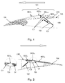
- Fig.1 illustrates a simplified cross-section of a part of an aircraft wing 100 with an upper surface element 101 driven by a first actuator powered mechanism 102.
- the upper surface element 101 represents a high lift spoiler of the aircraft wing 100.
- a main air flow direction is indicated by the prominent arrows in Fig. 1 and Fig. 2 .
- the terms downstream/upstream referring to the main air flow direction.
- the interconnecting segment SEG 3 is interconnecting a downstream edge of SEG, with an upstream edge of SEG 2 , wherein the interconnecting segment SEG 3 is extending along the whole downstream edge of SEG 1 and the whole upstream edge of SEG 2 .
- the interconnecting segment SEG 3 further exhibits a mechanical pretension causing a convex shape of the upper surface element if no forces acting to the upper surface element.
- a link element LNK is interconnecting an upstream edge of SEG 1 with an upper surface 103 of the aircraft wing.
- the link element LNK is realized as a strip made of a resiliently flexible material, wherein a downstream edge of the strip is extending along the whole upstream edge of SEG 1 and a whole upstream edge of the strip is connected with the upper surface of the aircraft wing 100.
- the link element LNK also exhibits a mechanical pretension contributing to the convex shape of the upper surface element if no forces acting to the upper surface element.
- the first actuator powered mechanism 102 is interconnecting a contact C1 on a lower side of the upper surface element 101 with a contact C2 on an inner structure of the aircraft wing, wherein the first actuator powered mechanism 102 controls the shape of the upper surface element 101 by controlling the distance between C1 and C2 while a downstream edge of segment SEG 2 is resting freely on a successive upper surface 103 of an attached trailing edge flap 105 connected to the aircraft wing 100.
- the right and left side edges of the upper surface element 101 are resting freely on a successive upper surface of the aircraft wing.
- the second status is reached by reducing the distance between points C1 and C2 from a reference distance in the reference status. While reducing the distance the first actuator powered mechanism 102 is generating a force pulling the point C1 towards the point C2 (indicated by a black arrow). Controlling the distance between the point C1 and C2 directly affects the cross-section of the upper surface element 101 and the related bump height of the respective shock control bump.
- Fig. 2 illustrates a simplified cross-section of a part of an aircraft wing with an upper surface element 101 driven by a first 102 and a second 105 actuator powered mechanism.
- the second actuator powered mechanism 105 is interconnecting a connection C3 on a lower side of segment SEG 1 and a connection C4 on a lower side of segment SEG 2 , wherein the second actuator powered mechanism 105 controls a distance between connections C3 and C4.
- the second actuator powered mechanism 105 is used for fine-tuning the shape of the cross-section of the upper surface element 101 (e.g. the shape of the shock control bump).
- the aircraft wing 100 further comprises a unit (not shown) controlling an actuator of the first actuator powered mechanism 102 and an actuator of the second actuator powered mechanism 105 depending on an actual airspeed or Mach number.
Landscapes
- Engineering & Computer Science (AREA)
- Aviation & Aerospace Engineering (AREA)
- Mechanical Engineering (AREA)
- Automation & Control Theory (AREA)
- Tires In General (AREA)
Abstract
Description
- The invention relates to an aircraft wing with an upper surface element and a first actuator powered mechanism for varying the shape of the upper surface element, wherein the upper surface element acting as adaptive "shock control bump".
- It is known that so-called "shock control bumps" (SCB's) are useful to reduce the characteristic impedance of an aircraft wing. Shock control bumps are a relatively new class of flow control devices that offer a number of potential performance benefits for (transonic or supersonic) applications where shock waves are present. They have most commonly been considered as a means for improving the performance of transonic wings, through the manipulation of the air flow over the upper wing surface where near-normal shockwave exists, resulting in a reduced characteristic impedance of the aircraft wing and an improved buffeting behaviour.
- As the name suggests, conventional SCB's consist of a physical bump placed on the aerodynamic surface where shockwave is known to occur. By far the most common application considered is the upper surface of a transonic wing. In this application SCBs can have a beneficial smearing effect on the structure of the near normal shockwave close to the wing surface. Specifically, SCB's split the shock into a number of weaker (oblique) shocks or compression waves that decelerate the flow more gradually (and hence more isentropically) than the single uncontrolled shockwave, thus incurring a reduced stagnation pressure loss and lower drag. A typical SCB consists of a ramp upstream of the nominal shock location, followed by a short crest region and then a tail. The ramp generates an oblique shock (or multiple oblique compression waves) and the main shockwave which deflects the incoming supersonic flow away from the surface. Around the crest region, the flow is decelerated to subsonic velocities by a near-normal shockwave, before the tail brings the post-shock flow back to the aircraft wing surface.
- It is the object of the invention to provide an aircraft wing with an adaptive shock control bump allowing an improvement of the performance of the aircraft wing and which especially contributes to an improvement of the buffeting behaviour and a reduction of the characteristic impedance of the aircraft wing.
- A first aspect of the invention provides an aircraft wing with an upper surface element and a first actuator powered mechanism for varying the shape of the upper surface element, wherein the surface element comprising: an upstream segment SEG1 with a stiffness S1, a downstream segment SEG2 with a stiffness S2, an interconnecting segment SEG3 with a stiffness S3, the interconnecting segment SEG3 is interconnecting a downstream edge of SEG1 with an upstream edge of SEG2, wherein the interconnecting segment SEG3 is extending along the whole downstream edge of SEG1 and the whole upstream edge of SEG2, or at least along a major part of the downstream edge of SEG1 and a major part of the upstream edge of SEG2, and the interconnecting segment SEG3 exhibits a mechanical pretension causing a convex shape of the upper surface element (especially if no forces acting to the upper surface element), with: S3 < S1, S2.
- The surface element further comprising a link element LNK, the link element LNK is interconnecting an upstream edge of the upstream segment SEG1 with an upper surface of the aircraft wing.
- Further, the first actuator powered mechanism is interconnecting a contact C1 on a lower side of the upper surface element with a contact C2 on an inner structure of the aircraft wing, wherein the first actuator powered mechanism controls the shape of the upper surface element by controlling the distance between C1 and C2.
- The terms "upstream" and "downstream" are referring to a main flow direction across the aircraft wing when airborne. Right and left edges of the upper surface element are the edges of the upper surface element orientated perpendicular to the air flow direction across the aircraft wing. In a preferred embodiment the upper surface element has a rectangular shape from a top view.
- The term "stiffness" refers to a structural (mechanical) stiffness of the respective segment or link element. In a preferred embodiment the segments SEG1, SEG2 are made of a metal, a metal alloy, a carbon fiber composite, a glass fiber composite or a mixture thereof. In a preferred embodiment the interconnecting segment SEG3 and/or the link element LNK are made of a metal, a metal alloy, a carbon fiber composite, a glass fiber composite or a mixture thereof. In a preferred embodiment the stiffness of segments SEG1 and/or SEG2 are selected such that said segments are dimensionally stable at least under operational air loads on the upper surface element. In a preferred embodiment the stiffness of segment SEG3 is selected such that, firstly based on the mechanical pretension a convex shape of the upper surface element is conserved if no forces, especially no air load (air forces) are acting on the upper surface element, and secondly that the interconnecting segment SEG3 is resiliently flexible enough for allowing a variation of the shape of the upper surface element induced by the first actuator powered mechanism. In a preferred embodiment the stiffness S1 equals the stiffness S2: S1 = S2.
- In a preferred embodiment the upper surface element is a spoiler, particularly a high lift spoiler. Beneficially the high lift spoiler providing at least an airflow separation and a flow gap control functionality.
- In a preferred embodiment the upper surface element is located on the upper side of the aircraft wing at a position where a compression shockwave is located during flight.
- In a preferred embodiment the aircraft wing comprises more than one of said upper surface elements.
- In a preferred embodiment the whole upper surface element acts as shock control bump variable in shape. In a preferred embodiment the bump height BH, which is defined as the elevation of the upper surface element above the surrounding upper surface of the aircraft wing, is controlled by the first actuator powered mechanism between 0 and a given maximum bump height MAXBH: BH ∈ [0, MAXBH]. In a preferred embodiment the upper surface element is manufactured with a maximum bump height mainly generated by the mechanical pretension of segment SEG3. In a preferred embodiment the maximum bump height is available in a status where no forces are applied to the upper surface element, either from air loads or from the first actuator powered mechanism. In a preferred embodiment the status defined by BH = 0 indicates that the upper surface element has a flat shaped cross-section, thus the aircraft wing in this case comprises no shock control bump.
- Based on the adaptive / controllable shape of the upper surface element, it is possible to reduce the shockwave intensity depending on respective flow velocities (e.g. airspeeds, Mach numbers) resulting in a reduced characteristic impedance of the aircraft wing and a reduced fuel burn of the respective aircraft. The shape of the upper surface element (=: shape of the shock control bump) further controls the position of the shockwave on the upper surface element and thus reduces the danger of buffeting considerably. The pretension of the segment SEG3 allows an integration of the upper surface element with adaptive shape (= adaptive shock control bump) into an aircraft wing with only minimal additional weight.
- A preferred embodiment of the aircraft wing is characterized in that the link element LNK comprises one or mores hinges. The hinges are made of a metal, a metal alloy, a carbon fiber composite, a glass fiber composite or a mixture thereof. The hinges are inherently stable and allow a deflection of the upper surface element about a hinge axis.
- In a preferred alternative embodiment of the aircraft wing the link element LNK is realized as a strip made of a resiliently flexible material with a stiffness S4, wherein a downstream edge of the strip is connected to and is extending along the whole upstream edge of SEG1 or at least along a major part of the upstream edge of SEG1, and a whole upstream edge of the strip is connected to the upper surface of the aircraft wing. In a preferred embodiment the stiffness S3 equals the stiffness S4: S3 = S4.
- In a preferred embodiment the upper surface element is connected to the aircraft wing exclusively via the link element LNK and the first actuator powered mechanism. All other parts of the upper surface element in this embodiment are not connected to the aircraft wing but may for example freely / movably rest on an ambient upper surface of the aircraft wing. The ambient upper surface and the first actuator powered mechanism inducing bending forces on the upper surface element.
- A preferred embodiment of the aircraft wing is characterized in that a downstream edge of segment SEG2 is resting freely on a successive upper surface of the aircraft wing or on a surface attached to the airfoil (e.g. a trailing edge flap). Another preferred embodiment of the aircraft wing is characterized in that side edges (right and/or left edges) of the upper surface element are resting freely on a successive upper surface of the aircraft wing. The mechanical support of the side edges and/or the mechanical support of the downstream edge of the upper surface element by a successive upper surface of the aircraft wing contributing to the shape variation by inducing bending forces on the upper surface element while controlling the distance between C1 and C2.
- A preferred embodiment of the aircraft wing is characterized in that a second actuator powered mechanism is interconnecting a connection C3 on a lower side of segment SEG1 and a connection C4 on a lower side of segment SEG2, wherein the second actuator powered mechanism controls a distance between connections C3 and C4. Controlling the distance between connections C3 and C4 directly controls the bending of the segment SEG3 and thus controls the shape of the upper surface element. The second actuator powered mechanism may therefore support the first actuator powered mechanism in controlling the shape of the upper surface element of the aircraft wing. In case the upper surface element is a spoiler, the first actuator powered mechanism may operationally also be used for deflecting the spoiler from the reference angle to a target deflection angle, whereas the second actuator powered mechanism may be used to control the shape of the upper surface element. The second actuator powered mechanism may also be used for fine-tuning the shape of the upper surface element predominantly controlled by the first actuator powered mechanism.
- A preferred embodiment of the aircraft wing is characterized in that the downstream segment SEG2 itself is consisting of an upstream segment SEG1* with a stiffness S1, a downstream segment SEG2* with a stiffness S2, an interconnecting segment SEG3* with a stiffness S3. The interconnecting segment SEG3* is interconnecting a downstream edge of SEG1* with an upstream edge of SEG2*, wherein the interconnecting segment SEG3* is extending along the whole downstream edge of SEG1* and the whole upstream edge of SEG2*, or at least along a major part of the downstream edge of SEG1* and a major part of the upstream edge of SEG2*, and the interconnecting segment SEG3* exhibits a mechanical pretension causing a convex shape of the upper surface element if no forces acting to the upper surface element, with: S3 < S1, S2.
- In a preferred embodiment a third actuator powered mechanism is interconnecting a connection C5 on a lower side of segment SEG1* and a connection C6 on a lower side of segment SEG2*, wherein the third actuator powered mechanism controls a distance between connections C5 and C6. This embodiment allows a higher degree shape variations of the upper surface element leading to an even better reduction of the shockwave intensity and resulting in an even better reduced characteristic impedance of the aircraft wing and a reduced fuel burn of the respective aircraft.
- A preferred embodiment of the aircraft wing is characterized in that the aircraft wing comprises a unit controlling an actuator of the first actuator powered mechanism and/or an actuator of the second actuator powered mechanism and/or an actuator of the third actuator powered mechanism depending on an actual airspeed or Mach number. The unit is preferably linked to an air data computer (ADC) of the respective aircraft for receiving the actual airspeed or Mach number input. The unit is driving the respective actuators beneficially based on the actual airspeed or Mach number input and based on given or calculated optimum shape data of the upper surface element.
- A second aspect of the invention provides an aircraft with an aircraft wing as described before.
-
- Fig. 1
- simplified cross-section of a part of an aircraft wing with an upper surface element driven by a first actuator powered mechanism and
- Fig. 2
- simplified cross-section of a part of an aircraft wing with an upper surface element driven by a first and a second actuator powered mechanism.
-
Fig.1 illustrates a simplified cross-section of a part of anaircraft wing 100 with anupper surface element 101 driven by a first actuator poweredmechanism 102. Theupper surface element 101 represents a high lift spoiler of theaircraft wing 100. - The
upper surface element 101 comprising an upstream segment SEG1 with a stiffness S1, a downstream segment SEG2 with a stiffness S2, an interconnecting segment SEG3 with a stiffness S3, with: S3 < S1, S2 and S1 = S2. A main air flow direction is indicated by the prominent arrows inFig. 1 and Fig. 2 . The terms downstream/upstream referring to the main air flow direction. - The interconnecting segment SEG3 is interconnecting a downstream edge of SEG, with an upstream edge of SEG2, wherein the interconnecting segment SEG3 is extending along the whole downstream edge of SEG1 and the whole upstream edge of SEG2. The interconnecting segment SEG3 further exhibits a mechanical pretension causing a convex shape of the upper surface element if no forces acting to the upper surface element.
- A link element LNK is interconnecting an upstream edge of SEG1 with an
upper surface 103 of the aircraft wing. The link element LNK is realized as a strip made of a resiliently flexible material, wherein a downstream edge of the strip is extending along the whole upstream edge of SEG1 and a whole upstream edge of the strip is connected with the upper surface of theaircraft wing 100. The link element LNK also exhibits a mechanical pretension contributing to the convex shape of the upper surface element if no forces acting to the upper surface element. - The first actuator powered
mechanism 102 is interconnecting a contact C1 on a lower side of theupper surface element 101 with a contact C2 on an inner structure of the aircraft wing, wherein the first actuator poweredmechanism 102 controls the shape of theupper surface element 101 by controlling the distance between C1 and C2 while a downstream edge of segment SEG2 is resting freely on a successiveupper surface 103 of an attached trailingedge flap 105 connected to theaircraft wing 100. The right and left side edges of theupper surface element 101 are resting freely on a successive upper surface of the aircraft wing. -
Fig. 1 shows theupper surface element 101 in a reference status with a maximum bump height BHmax and the second status where the bump height is zero BH = 0. The second status is reached by reducing the distance between points C1 and C2 from a reference distance in the reference status. While reducing the distance the first actuator poweredmechanism 102 is generating a force pulling the point C1 towards the point C2 (indicated by a black arrow). Controlling the distance between the point C1 and C2 directly affects the cross-section of theupper surface element 101 and the related bump height of the respective shock control bump. -
Fig. 2 illustrates a simplified cross-section of a part of an aircraft wing with anupper surface element 101 driven by a first 102 and a second 105 actuator powered mechanism. In addition to the features illustrated inFig. 1 the second actuator poweredmechanism 105 is interconnecting a connection C3 on a lower side of segment SEG1 and a connection C4 on a lower side of segment SEG2, wherein the second actuator poweredmechanism 105 controls a distance between connections C3 and C4. The second actuator poweredmechanism 105 is used for fine-tuning the shape of the cross-section of the upper surface element 101 (e.g. the shape of the shock control bump). - The
aircraft wing 100 further comprises a unit (not shown) controlling an actuator of the first actuator poweredmechanism 102 and an actuator of the second actuator poweredmechanism 105 depending on an actual airspeed or Mach number. -
- 100
- aircraft wing
- 101
- upper surface element
- 102
- first actuator powered mechanism
- 103
- upper surface of the aircraft wing
- 104
- trailing edge flap
- 105
- second actuator powered mechanism
Claims (14)
- Aircraft wing (100) with an upper surface element (101) and a first actuator powered mechanism (102) for varying the shape of the upper surface element (101), wherein- the surface element (101) is comprising:∘ an upstream segment SEG1 with a stiffness S1,∘ a downstream segment SEG2 with a stiffness S2,∘ an interconnecting segment SEG3 with a stiffness S3, the interconnecting segment SEG3 is interconnecting a downstream edge of SEG1 with an upstream edge of SEG2, wherein the interconnecting segment SEG3 is extending along the whole downstream edge of SEG1 and the whole upstream edge of SEG2, or at least along a major part of the downstream edge of SEG1 and a major part of the upstream edge of SEG2, and the interconnecting segment SEG3 exhibits a mechanical pretension causing a convex shape of the upper surface element, with: S3 < S1, S2,o a link element LNK, the link element LNK is interconnecting an upstream edge of SEG1 with an upper surface (103) of the aircraft wing, and- the first actuator powered mechanism (102) is interconnecting a contact C1 on a lower side of the upper surface element (101) with a contact C2 on an inner structure of the aircraft wing, wherein the first actuator powered mechanism (102) controls the shape of the upper surface element (101) by controlling the distance between C1 and C2.
- Aircraft wing (100) of claim 1,
characterized in that the link element LNK comprises one or mores hinges. - Aircraft wing (100) of claim 1,
characterized in that the link element LNK is realized as a strip made of a resiliently flexible material, wherein a downstream edge of the strip is extending along the whole upstream edge of SEG1 or at least along a major part of the upstream edge of SEG1, and a whole upstream edge of the strip is connected with the upper surface of the aircraft wing (100). - Aircraft wing (100) of claim 3,
characterized in that interconnecting segment SEG3 exhibits a mechanical pretension causing a convex shape of the upper surface element. - Aircraft wing (100) of any of the preceding claims,
characterized in that the upper surface element (101) is connected to the aircraft wing (100) exclusively via the link element LNK and the first actuator powered mechanism (102). - Aircraft wing (100) of any of the preceding claims,
characterized in that a downstream edge of segment SEG2 is resting freely on a successive upper surface (104) of the aircraft wing (100) or on a surface attached to the aircraft wing. - Aircraft wing (100) of any of the preceding claims,
characterized in that side edges of the upper surface element (101) are resting freely on a successive upper surface of the aircraft wing (100). - Aircraft wing (100) of any of the preceding claims,
characterized in that the stiffness S1 equals stiffness S2: S1 = S2. - Aircraft wing (100) of any of the preceding claims,
characterized in that the stiffness S3 equals stiffness S4: S3 = S4. - Aircraft wing (100) of any of the preceding claims,
characterized in that the downstream segment SEG2 is consisting of- an upstream segment SEG1* with a stiffness S1,- a downstream segment SEG2* with a stiffness S2,- an interconnecting segment SEG3* with a stiffness S3, the interconnecting segment SEG3* is interconnecting a downstream edge of SEG1* with an upstream edge of SEG2*, wherein the interconnecting segment SEG3* is extending along the whole downstream edge of SEG1* and the whole upstream edge of SEG2*, or at least along a major part of the downstream edge of SEG1* and a major part of the upstream edge of SEG2*, and the interconnecting segment SEG3* exhibits a mechanical pretension causing a convex shape of the upper surface element, with: S3 < S1, S2. - Aircraft wing (100) of any of the preceding claims,
characterized in that a second actuator powered mechanism (105) is interconnecting a connection C3 on a lower side of segment SEG1 and a connection C4 on a lower side of segment SEG2, wherein the second actuator powered mechanism (105) controls a distance between connections C3 and C4. - Aircraft wing (100) of any of the preceding claims,
characterized in that the aircraft wing (100) comprises a unit controlling an actuator of the first actuator powered mechanism (102) and/or an actuator of the second actuator powered mechanism (105) depending on an actual airspeed or Mach number. - Aircraft wing (100) of any of the preceding claims,
characterized in that the upper surface element (101) is a spoiler, particularly a high lift spoiler. - Aircraft with an aircraft wing (100) according to any of the preceding claims.
Priority Applications (3)
| Application Number | Priority Date | Filing Date | Title |
|---|---|---|---|
| EP15203195.1A EP3187412B1 (en) | 2015-12-30 | 2015-12-30 | Aircraft wing with an adaptive shock control bump |
| US15/384,520 US10427779B2 (en) | 2015-12-30 | 2016-12-20 | Aircraft wing with an adaptive shock control bump |
| CN201611240001.9A CN107054625B (en) | 2015-12-30 | 2016-12-28 | Aircraft wing with adaptive shock control protrusions |
Applications Claiming Priority (1)
| Application Number | Priority Date | Filing Date | Title |
|---|---|---|---|
| EP15203195.1A EP3187412B1 (en) | 2015-12-30 | 2015-12-30 | Aircraft wing with an adaptive shock control bump |
Publications (2)
| Publication Number | Publication Date |
|---|---|
| EP3187412A1 true EP3187412A1 (en) | 2017-07-05 |
| EP3187412B1 EP3187412B1 (en) | 2020-03-11 |
Family
ID=55066476
Family Applications (1)
| Application Number | Title | Priority Date | Filing Date |
|---|---|---|---|
| EP15203195.1A Active EP3187412B1 (en) | 2015-12-30 | 2015-12-30 | Aircraft wing with an adaptive shock control bump |
Country Status (3)
| Country | Link |
|---|---|
| US (1) | US10427779B2 (en) |
| EP (1) | EP3187412B1 (en) |
| CN (1) | CN107054625B (en) |
Families Citing this family (3)
| Publication number | Priority date | Publication date | Assignee | Title |
|---|---|---|---|---|
| JP6492138B2 (en) * | 2017-08-29 | 2019-03-27 | 株式会社Subaru | Aircraft wing load reduction device and aircraft wing load reduction method |
| CN109436293B (en) * | 2018-11-21 | 2020-05-22 | 南京航空航天大学 | A shock wave control device |
| DE102020116350B4 (en) | 2020-06-22 | 2024-07-25 | Deutsches Zentrum für Luft- und Raumfahrt e.V. | Transonic wing with a spoiler that can be deformed to form a shock control bump |
Citations (3)
| Publication number | Priority date | Publication date | Assignee | Title |
|---|---|---|---|---|
| US5918834A (en) * | 1997-02-27 | 1999-07-06 | Mcdonnell Douglas | Retractable sensor system for an aircraft |
| US6209824B1 (en) * | 1997-09-17 | 2001-04-03 | The Boeing Company | Control surface for an aircraft |
| US20060060720A1 (en) * | 2004-03-31 | 2006-03-23 | Bogue David R | Methods and systems for controlling lower surface shocks |
Family Cites Families (10)
| Publication number | Priority date | Publication date | Assignee | Title |
|---|---|---|---|---|
| GB9116787D0 (en) * | 1991-08-01 | 1991-09-18 | Secr Defence | Article having an aerofoil section with a distensible expansion surface |
| US5213287A (en) * | 1991-11-04 | 1993-05-25 | Barron David R | Wing modification method and apparatus |
| FR2704513B1 (en) * | 1993-04-27 | 1995-07-21 | Outil | IMPROVEMENTS ON AERO- AND HYDRO-DYNAMIC PROFILES CALLED NLF (FOR "NATURAL LAMINAR FLOW"). |
| US6994297B1 (en) * | 2004-10-27 | 2006-02-07 | The Boeing Company | Method and apparatus for controlling a vehicle |
| US8016245B2 (en) * | 2006-10-18 | 2011-09-13 | The Boeing Company | Dynamic bumps for drag reduction at transonic-supersonic speeds |
| DE102007009060A1 (en) * | 2007-02-23 | 2008-08-28 | Airbus Deutschland Gmbh | Spoiler for an aerodynamically effective surface of an aircraft |
| GB0803727D0 (en) * | 2008-02-29 | 2008-04-09 | Airbus Uk Ltd | Aerodynamic structure with series of shock bumps |
| GB201002281D0 (en) * | 2010-02-11 | 2010-03-31 | Univ Sheffield | Apparatus and method for aerodynamic drag reduction |
| US8887482B1 (en) * | 2010-02-12 | 2014-11-18 | The Boeing Company | Active flow control with pulse detonation actuators |
| GB2512318A (en) * | 2013-03-26 | 2014-10-01 | Eads Uk Ltd | Lift-reducing apparatus for aircraft wings |
-
2015
- 2015-12-30 EP EP15203195.1A patent/EP3187412B1/en active Active
-
2016
- 2016-12-20 US US15/384,520 patent/US10427779B2/en active Active
- 2016-12-28 CN CN201611240001.9A patent/CN107054625B/en active Active
Patent Citations (3)
| Publication number | Priority date | Publication date | Assignee | Title |
|---|---|---|---|---|
| US5918834A (en) * | 1997-02-27 | 1999-07-06 | Mcdonnell Douglas | Retractable sensor system for an aircraft |
| US6209824B1 (en) * | 1997-09-17 | 2001-04-03 | The Boeing Company | Control surface for an aircraft |
| US20060060720A1 (en) * | 2004-03-31 | 2006-03-23 | Bogue David R | Methods and systems for controlling lower surface shocks |
Also Published As
| Publication number | Publication date |
|---|---|
| US20170190411A1 (en) | 2017-07-06 |
| CN107054625A (en) | 2017-08-18 |
| CN107054625B (en) | 2021-01-12 |
| EP3187412B1 (en) | 2020-03-11 |
| US10427779B2 (en) | 2019-10-01 |
Similar Documents
| Publication | Publication Date | Title |
|---|---|---|
| US9422050B2 (en) | Fore flap disposed on the wing of an aircraft | |
| EP2125510B1 (en) | Spoiler for an aerodynamic body of an aircraft | |
| JP6196795B2 (en) | Performance-enhanced winglet system and method | |
| US7475848B2 (en) | Wing employing leading edge flaps and winglets to achieve improved aerodynamic performance | |
| US9457887B2 (en) | Smart material trailing edge variable chord morphing wing | |
| US5921506A (en) | Extendible leading edge flap | |
| CN109895992B (en) | Pre-deformed aircraft spoiler and flap designed to seal with flaps in deflected state | |
| US6910327B2 (en) | Apparatus and methods for varying inlet lip geometry of a jet engine inlet | |
| JP2015214328A (en) | Morphing the wing leading edge | |
| US10427779B2 (en) | Aircraft wing with an adaptive shock control bump | |
| US20050116116A1 (en) | Wing employing leading edge flaps and winglets to achieve improved aerodynamic performance | |
| Moore et al. | X-29 forward swept wing aerodynamic overview | |
| EP3348472B1 (en) | Lifting surface | |
| US20050045763A1 (en) | Aircraft lift device for low sonic boom | |
| RU2408498C2 (en) | Aircraft flexible control surface | |
| US20160214705A1 (en) | Flap mechanism and associated method | |
| US7004428B2 (en) | Lift and twist control using trailing edge control surfaces on supersonic laminar flow wings | |
| CN107010203A (en) | Aircraft wing with flow spoiler | |
| EP3498595A1 (en) | Cruise miniflaps for aircraft | |
| US12172747B2 (en) | Flow control device | |
| GB2587429A (en) | Wingtip device for an aircraft | |
| US11794908B2 (en) | Flow body for an aircraft having an integrated de-icing system | |
| US6299109B1 (en) | Spoiler for wings | |
| US20190256188A1 (en) | Airfoil Modification To Improve Fuel Efficiency | |
| US10150557B2 (en) | Shape-variable gap covering between control surfaces and adjacent structural components on aircrafts |
Legal Events
| Date | Code | Title | Description |
|---|---|---|---|
| PUAI | Public reference made under article 153(3) epc to a published international application that has entered the european phase |
Free format text: ORIGINAL CODE: 0009012 |
|
| STAA | Information on the status of an ep patent application or granted ep patent |
Free format text: STATUS: THE APPLICATION HAS BEEN PUBLISHED |
|
| AK | Designated contracting states |
Kind code of ref document: A1 Designated state(s): AL AT BE BG CH CY CZ DE DK EE ES FI FR GB GR HR HU IE IS IT LI LT LU LV MC MK MT NL NO PL PT RO RS SE SI SK SM TR |
|
| AX | Request for extension of the european patent |
Extension state: BA ME |
|
| STAA | Information on the status of an ep patent application or granted ep patent |
Free format text: STATUS: REQUEST FOR EXAMINATION WAS MADE |
|
| 17P | Request for examination filed |
Effective date: 20171002 |
|
| RBV | Designated contracting states (corrected) |
Designated state(s): AL AT BE BG CH CY CZ DE DK EE ES FI FR GB GR HR HU IE IS IT LI LT LU LV MC MK MT NL NO PL PT RO RS SE SI SK SM TR |
|
| STAA | Information on the status of an ep patent application or granted ep patent |
Free format text: STATUS: EXAMINATION IS IN PROGRESS |
|
| 17Q | First examination report despatched |
Effective date: 20181122 |
|
| GRAP | Despatch of communication of intention to grant a patent |
Free format text: ORIGINAL CODE: EPIDOSNIGR1 |
|
| STAA | Information on the status of an ep patent application or granted ep patent |
Free format text: STATUS: GRANT OF PATENT IS INTENDED |
|
| GRAJ | Information related to disapproval of communication of intention to grant by the applicant or resumption of examination proceedings by the epo deleted |
Free format text: ORIGINAL CODE: EPIDOSDIGR1 |
|
| STAA | Information on the status of an ep patent application or granted ep patent |
Free format text: STATUS: EXAMINATION IS IN PROGRESS |
|
| GRAP | Despatch of communication of intention to grant a patent |
Free format text: ORIGINAL CODE: EPIDOSNIGR1 |
|
| STAA | Information on the status of an ep patent application or granted ep patent |
Free format text: STATUS: GRANT OF PATENT IS INTENDED |
|
| INTG | Intention to grant announced |
Effective date: 20190814 |
|
| INTC | Intention to grant announced (deleted) | ||
| INTG | Intention to grant announced |
Effective date: 20190911 |
|
| GRAS | Grant fee paid |
Free format text: ORIGINAL CODE: EPIDOSNIGR3 |
|
| GRAA | (expected) grant |
Free format text: ORIGINAL CODE: 0009210 |
|
| STAA | Information on the status of an ep patent application or granted ep patent |
Free format text: STATUS: THE PATENT HAS BEEN GRANTED |
|
| AK | Designated contracting states |
Kind code of ref document: B1 Designated state(s): AL AT BE BG CH CY CZ DE DK EE ES FI FR GB GR HR HU IE IS IT LI LT LU LV MC MK MT NL NO PL PT RO RS SE SI SK SM TR |
|
| REG | Reference to a national code |
Ref country code: GB Ref legal event code: FG4D |
|
| REG | Reference to a national code |
Ref country code: CH Ref legal event code: EP |
|
| REG | Reference to a national code |
Ref country code: AT Ref legal event code: REF Ref document number: 1242845 Country of ref document: AT Kind code of ref document: T Effective date: 20200315 |
|
| REG | Reference to a national code |
Ref country code: IE Ref legal event code: FG4D |
|
| REG | Reference to a national code |
Ref country code: DE Ref legal event code: R096 Ref document number: 602015048508 Country of ref document: DE |
|
| PG25 | Lapsed in a contracting state [announced via postgrant information from national office to epo] |
Ref country code: NO Free format text: LAPSE BECAUSE OF FAILURE TO SUBMIT A TRANSLATION OF THE DESCRIPTION OR TO PAY THE FEE WITHIN THE PRESCRIBED TIME-LIMIT Effective date: 20200611 Ref country code: RS Free format text: LAPSE BECAUSE OF FAILURE TO SUBMIT A TRANSLATION OF THE DESCRIPTION OR TO PAY THE FEE WITHIN THE PRESCRIBED TIME-LIMIT Effective date: 20200311 Ref country code: FI Free format text: LAPSE BECAUSE OF FAILURE TO SUBMIT A TRANSLATION OF THE DESCRIPTION OR TO PAY THE FEE WITHIN THE PRESCRIBED TIME-LIMIT Effective date: 20200311 |
|
| REG | Reference to a national code |
Ref country code: NL Ref legal event code: MP Effective date: 20200311 |
|
| PG25 | Lapsed in a contracting state [announced via postgrant information from national office to epo] |
Ref country code: LV Free format text: LAPSE BECAUSE OF FAILURE TO SUBMIT A TRANSLATION OF THE DESCRIPTION OR TO PAY THE FEE WITHIN THE PRESCRIBED TIME-LIMIT Effective date: 20200311 Ref country code: SE Free format text: LAPSE BECAUSE OF FAILURE TO SUBMIT A TRANSLATION OF THE DESCRIPTION OR TO PAY THE FEE WITHIN THE PRESCRIBED TIME-LIMIT Effective date: 20200311 Ref country code: GR Free format text: LAPSE BECAUSE OF FAILURE TO SUBMIT A TRANSLATION OF THE DESCRIPTION OR TO PAY THE FEE WITHIN THE PRESCRIBED TIME-LIMIT Effective date: 20200612 Ref country code: HR Free format text: LAPSE BECAUSE OF FAILURE TO SUBMIT A TRANSLATION OF THE DESCRIPTION OR TO PAY THE FEE WITHIN THE PRESCRIBED TIME-LIMIT Effective date: 20200311 Ref country code: BG Free format text: LAPSE BECAUSE OF FAILURE TO SUBMIT A TRANSLATION OF THE DESCRIPTION OR TO PAY THE FEE WITHIN THE PRESCRIBED TIME-LIMIT Effective date: 20200611 |
|
| REG | Reference to a national code |
Ref country code: LT Ref legal event code: MG4D |
|
| PG25 | Lapsed in a contracting state [announced via postgrant information from national office to epo] |
Ref country code: NL Free format text: LAPSE BECAUSE OF FAILURE TO SUBMIT A TRANSLATION OF THE DESCRIPTION OR TO PAY THE FEE WITHIN THE PRESCRIBED TIME-LIMIT Effective date: 20200311 |
|
| PG25 | Lapsed in a contracting state [announced via postgrant information from national office to epo] |
Ref country code: IS Free format text: LAPSE BECAUSE OF FAILURE TO SUBMIT A TRANSLATION OF THE DESCRIPTION OR TO PAY THE FEE WITHIN THE PRESCRIBED TIME-LIMIT Effective date: 20200711 Ref country code: SK Free format text: LAPSE BECAUSE OF FAILURE TO SUBMIT A TRANSLATION OF THE DESCRIPTION OR TO PAY THE FEE WITHIN THE PRESCRIBED TIME-LIMIT Effective date: 20200311 Ref country code: PT Free format text: LAPSE BECAUSE OF FAILURE TO SUBMIT A TRANSLATION OF THE DESCRIPTION OR TO PAY THE FEE WITHIN THE PRESCRIBED TIME-LIMIT Effective date: 20200805 Ref country code: RO Free format text: LAPSE BECAUSE OF FAILURE TO SUBMIT A TRANSLATION OF THE DESCRIPTION OR TO PAY THE FEE WITHIN THE PRESCRIBED TIME-LIMIT Effective date: 20200311 Ref country code: CZ Free format text: LAPSE BECAUSE OF FAILURE TO SUBMIT A TRANSLATION OF THE DESCRIPTION OR TO PAY THE FEE WITHIN THE PRESCRIBED TIME-LIMIT Effective date: 20200311 Ref country code: SM Free format text: LAPSE BECAUSE OF FAILURE TO SUBMIT A TRANSLATION OF THE DESCRIPTION OR TO PAY THE FEE WITHIN THE PRESCRIBED TIME-LIMIT Effective date: 20200311 Ref country code: EE Free format text: LAPSE BECAUSE OF FAILURE TO SUBMIT A TRANSLATION OF THE DESCRIPTION OR TO PAY THE FEE WITHIN THE PRESCRIBED TIME-LIMIT Effective date: 20200311 Ref country code: LT Free format text: LAPSE BECAUSE OF FAILURE TO SUBMIT A TRANSLATION OF THE DESCRIPTION OR TO PAY THE FEE WITHIN THE PRESCRIBED TIME-LIMIT Effective date: 20200311 |
|
| REG | Reference to a national code |
Ref country code: AT Ref legal event code: MK05 Ref document number: 1242845 Country of ref document: AT Kind code of ref document: T Effective date: 20200311 |
|
| REG | Reference to a national code |
Ref country code: DE Ref legal event code: R097 Ref document number: 602015048508 Country of ref document: DE |
|
| PLBE | No opposition filed within time limit |
Free format text: ORIGINAL CODE: 0009261 |
|
| STAA | Information on the status of an ep patent application or granted ep patent |
Free format text: STATUS: NO OPPOSITION FILED WITHIN TIME LIMIT |
|
| PG25 | Lapsed in a contracting state [announced via postgrant information from national office to epo] |
Ref country code: ES Free format text: LAPSE BECAUSE OF FAILURE TO SUBMIT A TRANSLATION OF THE DESCRIPTION OR TO PAY THE FEE WITHIN THE PRESCRIBED TIME-LIMIT Effective date: 20200311 Ref country code: DK Free format text: LAPSE BECAUSE OF FAILURE TO SUBMIT A TRANSLATION OF THE DESCRIPTION OR TO PAY THE FEE WITHIN THE PRESCRIBED TIME-LIMIT Effective date: 20200311 Ref country code: IT Free format text: LAPSE BECAUSE OF FAILURE TO SUBMIT A TRANSLATION OF THE DESCRIPTION OR TO PAY THE FEE WITHIN THE PRESCRIBED TIME-LIMIT Effective date: 20200311 Ref country code: AT Free format text: LAPSE BECAUSE OF FAILURE TO SUBMIT A TRANSLATION OF THE DESCRIPTION OR TO PAY THE FEE WITHIN THE PRESCRIBED TIME-LIMIT Effective date: 20200311 |
|
| 26N | No opposition filed |
Effective date: 20201214 |
|
| PG25 | Lapsed in a contracting state [announced via postgrant information from national office to epo] |
Ref country code: PL Free format text: LAPSE BECAUSE OF FAILURE TO SUBMIT A TRANSLATION OF THE DESCRIPTION OR TO PAY THE FEE WITHIN THE PRESCRIBED TIME-LIMIT Effective date: 20200311 Ref country code: SI Free format text: LAPSE BECAUSE OF FAILURE TO SUBMIT A TRANSLATION OF THE DESCRIPTION OR TO PAY THE FEE WITHIN THE PRESCRIBED TIME-LIMIT Effective date: 20200311 |
|
| REG | Reference to a national code |
Ref country code: CH Ref legal event code: PL |
|
| GBPC | Gb: european patent ceased through non-payment of renewal fee |
Effective date: 20201230 |
|
| PG25 | Lapsed in a contracting state [announced via postgrant information from national office to epo] |
Ref country code: MC Free format text: LAPSE BECAUSE OF FAILURE TO SUBMIT A TRANSLATION OF THE DESCRIPTION OR TO PAY THE FEE WITHIN THE PRESCRIBED TIME-LIMIT Effective date: 20200311 |
|
| REG | Reference to a national code |
Ref country code: BE Ref legal event code: MM Effective date: 20201231 |
|
| PG25 | Lapsed in a contracting state [announced via postgrant information from national office to epo] |
Ref country code: IE Free format text: LAPSE BECAUSE OF NON-PAYMENT OF DUE FEES Effective date: 20201230 Ref country code: LU Free format text: LAPSE BECAUSE OF NON-PAYMENT OF DUE FEES Effective date: 20201230 |
|
| PG25 | Lapsed in a contracting state [announced via postgrant information from national office to epo] |
Ref country code: CH Free format text: LAPSE BECAUSE OF NON-PAYMENT OF DUE FEES Effective date: 20201231 Ref country code: GB Free format text: LAPSE BECAUSE OF NON-PAYMENT OF DUE FEES Effective date: 20201230 Ref country code: LI Free format text: LAPSE BECAUSE OF NON-PAYMENT OF DUE FEES Effective date: 20201231 |
|
| PG25 | Lapsed in a contracting state [announced via postgrant information from national office to epo] |
Ref country code: TR Free format text: LAPSE BECAUSE OF FAILURE TO SUBMIT A TRANSLATION OF THE DESCRIPTION OR TO PAY THE FEE WITHIN THE PRESCRIBED TIME-LIMIT Effective date: 20200311 Ref country code: MT Free format text: LAPSE BECAUSE OF FAILURE TO SUBMIT A TRANSLATION OF THE DESCRIPTION OR TO PAY THE FEE WITHIN THE PRESCRIBED TIME-LIMIT Effective date: 20200311 Ref country code: CY Free format text: LAPSE BECAUSE OF FAILURE TO SUBMIT A TRANSLATION OF THE DESCRIPTION OR TO PAY THE FEE WITHIN THE PRESCRIBED TIME-LIMIT Effective date: 20200311 |
|
| PG25 | Lapsed in a contracting state [announced via postgrant information from national office to epo] |
Ref country code: MK Free format text: LAPSE BECAUSE OF FAILURE TO SUBMIT A TRANSLATION OF THE DESCRIPTION OR TO PAY THE FEE WITHIN THE PRESCRIBED TIME-LIMIT Effective date: 20200311 Ref country code: AL Free format text: LAPSE BECAUSE OF FAILURE TO SUBMIT A TRANSLATION OF THE DESCRIPTION OR TO PAY THE FEE WITHIN THE PRESCRIBED TIME-LIMIT Effective date: 20200311 |
|
| PG25 | Lapsed in a contracting state [announced via postgrant information from national office to epo] |
Ref country code: BE Free format text: LAPSE BECAUSE OF NON-PAYMENT OF DUE FEES Effective date: 20201231 |
|
| PGFP | Annual fee paid to national office [announced via postgrant information from national office to epo] |
Ref country code: DE Payment date: 20251211 Year of fee payment: 11 |
|
| PGFP | Annual fee paid to national office [announced via postgrant information from national office to epo] |
Ref country code: FR Payment date: 20251223 Year of fee payment: 11 |