EP3187301A1 - Tool changing method and tool changing device - Google Patents
Tool changing method and tool changing device Download PDFInfo
- Publication number
- EP3187301A1 EP3187301A1 EP15835275.7A EP15835275A EP3187301A1 EP 3187301 A1 EP3187301 A1 EP 3187301A1 EP 15835275 A EP15835275 A EP 15835275A EP 3187301 A1 EP3187301 A1 EP 3187301A1
- Authority
- EP
- European Patent Office
- Prior art keywords
- tool
- change arm
- support shaft
- spindle
- tool change
- Prior art date
- Legal status (The legal status is an assumption and is not a legal conclusion. Google has not performed a legal analysis and makes no representation as to the accuracy of the status listed.)
- Granted
Links
Images



Classifications
-
- B—PERFORMING OPERATIONS; TRANSPORTING
- B23—MACHINE TOOLS; METAL-WORKING NOT OTHERWISE PROVIDED FOR
- B23Q—DETAILS, COMPONENTS, OR ACCESSORIES FOR MACHINE TOOLS, e.g. ARRANGEMENTS FOR COPYING OR CONTROLLING; MACHINE TOOLS IN GENERAL CHARACTERISED BY THE CONSTRUCTION OF PARTICULAR DETAILS OR COMPONENTS; COMBINATIONS OR ASSOCIATIONS OF METAL-WORKING MACHINES, NOT DIRECTED TO A PARTICULAR RESULT
- B23Q3/00—Devices holding, supporting, or positioning work or tools, of a kind normally removable from the machine
- B23Q3/155—Arrangements for automatic insertion or removal of tools, e.g. combined with manual handling
- B23Q3/157—Arrangements for automatic insertion or removal of tools, e.g. combined with manual handling of rotary tools
- B23Q3/15713—Arrangements for automatic insertion or removal of tools, e.g. combined with manual handling of rotary tools a transfer device taking a single tool from a storage device and inserting it in a spindle
- B23Q3/1572—Arrangements for automatic insertion or removal of tools, e.g. combined with manual handling of rotary tools a transfer device taking a single tool from a storage device and inserting it in a spindle the storage device comprising rotating or circulating storing means
- B23Q3/15726—Arrangements for automatic insertion or removal of tools, e.g. combined with manual handling of rotary tools a transfer device taking a single tool from a storage device and inserting it in a spindle the storage device comprising rotating or circulating storing means the storage means rotating or circulating in a plane parallel to the axis of the spindle
- B23Q3/1574—Arrangements for automatic insertion or removal of tools, e.g. combined with manual handling of rotary tools a transfer device taking a single tool from a storage device and inserting it in a spindle the storage device comprising rotating or circulating storing means the storage means rotating or circulating in a plane parallel to the axis of the spindle the axis of the stored tools being arranged perpendicularly to the rotating or circulating plane of the storage means
- B23Q3/15746—Arrangements for automatic insertion or removal of tools, e.g. combined with manual handling of rotary tools a transfer device taking a single tool from a storage device and inserting it in a spindle the storage device comprising rotating or circulating storing means the storage means rotating or circulating in a plane parallel to the axis of the spindle the axis of the stored tools being arranged perpendicularly to the rotating or circulating plane of the storage means the storage means comprising pivotable tool storage elements
-
- B—PERFORMING OPERATIONS; TRANSPORTING
- B23—MACHINE TOOLS; METAL-WORKING NOT OTHERWISE PROVIDED FOR
- B23Q—DETAILS, COMPONENTS, OR ACCESSORIES FOR MACHINE TOOLS, e.g. ARRANGEMENTS FOR COPYING OR CONTROLLING; MACHINE TOOLS IN GENERAL CHARACTERISED BY THE CONSTRUCTION OF PARTICULAR DETAILS OR COMPONENTS; COMBINATIONS OR ASSOCIATIONS OF METAL-WORKING MACHINES, NOT DIRECTED TO A PARTICULAR RESULT
- B23Q3/00—Devices holding, supporting, or positioning work or tools, of a kind normally removable from the machine
- B23Q3/155—Arrangements for automatic insertion or removal of tools, e.g. combined with manual handling
- B23Q3/157—Arrangements for automatic insertion or removal of tools, e.g. combined with manual handling of rotary tools
- B23Q3/15713—Arrangements for automatic insertion or removal of tools, e.g. combined with manual handling of rotary tools a transfer device taking a single tool from a storage device and inserting it in a spindle
- B23Q3/1572—Arrangements for automatic insertion or removal of tools, e.g. combined with manual handling of rotary tools a transfer device taking a single tool from a storage device and inserting it in a spindle the storage device comprising rotating or circulating storing means
- B23Q3/15726—Arrangements for automatic insertion or removal of tools, e.g. combined with manual handling of rotary tools a transfer device taking a single tool from a storage device and inserting it in a spindle the storage device comprising rotating or circulating storing means the storage means rotating or circulating in a plane parallel to the axis of the spindle
- B23Q3/1574—Arrangements for automatic insertion or removal of tools, e.g. combined with manual handling of rotary tools a transfer device taking a single tool from a storage device and inserting it in a spindle the storage device comprising rotating or circulating storing means the storage means rotating or circulating in a plane parallel to the axis of the spindle the axis of the stored tools being arranged perpendicularly to the rotating or circulating plane of the storage means
-
- B—PERFORMING OPERATIONS; TRANSPORTING
- B23—MACHINE TOOLS; METAL-WORKING NOT OTHERWISE PROVIDED FOR
- B23Q—DETAILS, COMPONENTS, OR ACCESSORIES FOR MACHINE TOOLS, e.g. ARRANGEMENTS FOR COPYING OR CONTROLLING; MACHINE TOOLS IN GENERAL CHARACTERISED BY THE CONSTRUCTION OF PARTICULAR DETAILS OR COMPONENTS; COMBINATIONS OR ASSOCIATIONS OF METAL-WORKING MACHINES, NOT DIRECTED TO A PARTICULAR RESULT
- B23Q11/00—Accessories fitted to machine tools for keeping tools or parts of the machine in good working condition or for cooling work; Safety devices specially combined with or arranged in, or specially adapted for use in connection with, machine tools
- B23Q11/0042—Devices for removing chips
-
- B—PERFORMING OPERATIONS; TRANSPORTING
- B23—MACHINE TOOLS; METAL-WORKING NOT OTHERWISE PROVIDED FOR
- B23Q—DETAILS, COMPONENTS, OR ACCESSORIES FOR MACHINE TOOLS, e.g. ARRANGEMENTS FOR COPYING OR CONTROLLING; MACHINE TOOLS IN GENERAL CHARACTERISED BY THE CONSTRUCTION OF PARTICULAR DETAILS OR COMPONENTS; COMBINATIONS OR ASSOCIATIONS OF METAL-WORKING MACHINES, NOT DIRECTED TO A PARTICULAR RESULT
- B23Q11/00—Accessories fitted to machine tools for keeping tools or parts of the machine in good working condition or for cooling work; Safety devices specially combined with or arranged in, or specially adapted for use in connection with, machine tools
- B23Q11/0042—Devices for removing chips
- B23Q11/005—Devices for removing chips by blowing
-
- B—PERFORMING OPERATIONS; TRANSPORTING
- B23—MACHINE TOOLS; METAL-WORKING NOT OTHERWISE PROVIDED FOR
- B23Q—DETAILS, COMPONENTS, OR ACCESSORIES FOR MACHINE TOOLS, e.g. ARRANGEMENTS FOR COPYING OR CONTROLLING; MACHINE TOOLS IN GENERAL CHARACTERISED BY THE CONSTRUCTION OF PARTICULAR DETAILS OR COMPONENTS; COMBINATIONS OR ASSOCIATIONS OF METAL-WORKING MACHINES, NOT DIRECTED TO A PARTICULAR RESULT
- B23Q3/00—Devices holding, supporting, or positioning work or tools, of a kind normally removable from the machine
- B23Q3/155—Arrangements for automatic insertion or removal of tools, e.g. combined with manual handling
- B23Q3/15503—Processes characterized by special sequencing of operations or the like, e.g. for optimizing tool changing time or capacity in tool storage
-
- B—PERFORMING OPERATIONS; TRANSPORTING
- B23—MACHINE TOOLS; METAL-WORKING NOT OTHERWISE PROVIDED FOR
- B23Q—DETAILS, COMPONENTS, OR ACCESSORIES FOR MACHINE TOOLS, e.g. ARRANGEMENTS FOR COPYING OR CONTROLLING; MACHINE TOOLS IN GENERAL CHARACTERISED BY THE CONSTRUCTION OF PARTICULAR DETAILS OR COMPONENTS; COMBINATIONS OR ASSOCIATIONS OF METAL-WORKING MACHINES, NOT DIRECTED TO A PARTICULAR RESULT
- B23Q3/00—Devices holding, supporting, or positioning work or tools, of a kind normally removable from the machine
- B23Q3/155—Arrangements for automatic insertion or removal of tools, e.g. combined with manual handling
- B23Q3/157—Arrangements for automatic insertion or removal of tools, e.g. combined with manual handling of rotary tools
- B23Q3/15713—Arrangements for automatic insertion or removal of tools, e.g. combined with manual handling of rotary tools a transfer device taking a single tool from a storage device and inserting it in a spindle
-
- B—PERFORMING OPERATIONS; TRANSPORTING
- B23—MACHINE TOOLS; METAL-WORKING NOT OTHERWISE PROVIDED FOR
- B23Q—DETAILS, COMPONENTS, OR ACCESSORIES FOR MACHINE TOOLS, e.g. ARRANGEMENTS FOR COPYING OR CONTROLLING; MACHINE TOOLS IN GENERAL CHARACTERISED BY THE CONSTRUCTION OF PARTICULAR DETAILS OR COMPONENTS; COMBINATIONS OR ASSOCIATIONS OF METAL-WORKING MACHINES, NOT DIRECTED TO A PARTICULAR RESULT
- B23Q3/00—Devices holding, supporting, or positioning work or tools, of a kind normally removable from the machine
- B23Q3/155—Arrangements for automatic insertion or removal of tools, e.g. combined with manual handling
- B23Q3/1552—Arrangements for automatic insertion or removal of tools, e.g. combined with manual handling parts of devices for automatically inserting or removing tools
- B23Q3/1554—Transfer mechanisms, e.g. tool gripping arms; Drive mechanisms therefore
- B23Q2003/155414—Transfer mechanisms, e.g. tool gripping arms; Drive mechanisms therefore the transfer mechanism comprising two or more grippers
- B23Q2003/155425—Transfer mechanisms, e.g. tool gripping arms; Drive mechanisms therefore the transfer mechanism comprising two or more grippers pivotable
- B23Q2003/155435—Transfer mechanisms, e.g. tool gripping arms; Drive mechanisms therefore the transfer mechanism comprising two or more grippers pivotable and linearly movable
- B23Q2003/155439—Transfer mechanisms, e.g. tool gripping arms; Drive mechanisms therefore the transfer mechanism comprising two or more grippers pivotable and linearly movable along the pivoting axis
-
- Y—GENERAL TAGGING OF NEW TECHNOLOGICAL DEVELOPMENTS; GENERAL TAGGING OF CROSS-SECTIONAL TECHNOLOGIES SPANNING OVER SEVERAL SECTIONS OF THE IPC; TECHNICAL SUBJECTS COVERED BY FORMER USPC CROSS-REFERENCE ART COLLECTIONS [XRACs] AND DIGESTS
- Y02—TECHNOLOGIES OR APPLICATIONS FOR MITIGATION OR ADAPTATION AGAINST CLIMATE CHANGE
- Y02P—CLIMATE CHANGE MITIGATION TECHNOLOGIES IN THE PRODUCTION OR PROCESSING OF GOODS
- Y02P70/00—Climate change mitigation technologies in the production process for final industrial or consumer products
- Y02P70/10—Greenhouse gas [GHG] capture, material saving, heat recovery or other energy efficient measures, e.g. motor control, characterised by manufacturing processes, e.g. for rolling metal or metal working
-
- Y—GENERAL TAGGING OF NEW TECHNOLOGICAL DEVELOPMENTS; GENERAL TAGGING OF CROSS-SECTIONAL TECHNOLOGIES SPANNING OVER SEVERAL SECTIONS OF THE IPC; TECHNICAL SUBJECTS COVERED BY FORMER USPC CROSS-REFERENCE ART COLLECTIONS [XRACs] AND DIGESTS
- Y10—TECHNICAL SUBJECTS COVERED BY FORMER USPC
- Y10T—TECHNICAL SUBJECTS COVERED BY FORMER US CLASSIFICATION
- Y10T483/00—Tool changing
- Y10T483/10—Process
-
- Y—GENERAL TAGGING OF NEW TECHNOLOGICAL DEVELOPMENTS; GENERAL TAGGING OF CROSS-SECTIONAL TECHNOLOGIES SPANNING OVER SEVERAL SECTIONS OF THE IPC; TECHNICAL SUBJECTS COVERED BY FORMER USPC CROSS-REFERENCE ART COLLECTIONS [XRACs] AND DIGESTS
- Y10—TECHNICAL SUBJECTS COVERED BY FORMER USPC
- Y10T—TECHNICAL SUBJECTS COVERED BY FORMER US CLASSIFICATION
- Y10T483/00—Tool changing
- Y10T483/15—Tool changing with means to condition or adjust tool or tool support
-
- Y—GENERAL TAGGING OF NEW TECHNOLOGICAL DEVELOPMENTS; GENERAL TAGGING OF CROSS-SECTIONAL TECHNOLOGIES SPANNING OVER SEVERAL SECTIONS OF THE IPC; TECHNICAL SUBJECTS COVERED BY FORMER USPC CROSS-REFERENCE ART COLLECTIONS [XRACs] AND DIGESTS
- Y10—TECHNICAL SUBJECTS COVERED BY FORMER USPC
- Y10T—TECHNICAL SUBJECTS COVERED BY FORMER US CLASSIFICATION
- Y10T483/00—Tool changing
- Y10T483/17—Tool changing including machine tool or component
- Y10T483/1733—Rotary spindle machine tool [e.g., milling machine, boring, machine, grinding machine, etc.]
- Y10T483/1748—Tool changer between spindle and matrix
- Y10T483/1752—Tool changer between spindle and matrix including tool holder pivotable about axis
- Y10T483/1755—Plural tool holders pivotable about common axis
-
- Y—GENERAL TAGGING OF NEW TECHNOLOGICAL DEVELOPMENTS; GENERAL TAGGING OF CROSS-SECTIONAL TECHNOLOGIES SPANNING OVER SEVERAL SECTIONS OF THE IPC; TECHNICAL SUBJECTS COVERED BY FORMER USPC CROSS-REFERENCE ART COLLECTIONS [XRACs] AND DIGESTS
- Y10—TECHNICAL SUBJECTS COVERED BY FORMER USPC
- Y10T—TECHNICAL SUBJECTS COVERED BY FORMER US CLASSIFICATION
- Y10T483/00—Tool changing
- Y10T483/17—Tool changing including machine tool or component
- Y10T483/1733—Rotary spindle machine tool [e.g., milling machine, boring, machine, grinding machine, etc.]
- Y10T483/1748—Tool changer between spindle and matrix
- Y10T483/1752—Tool changer between spindle and matrix including tool holder pivotable about axis
- Y10T483/1755—Plural tool holders pivotable about common axis
- Y10T483/1767—Linearly movable tool holders
Definitions
- the present invention relates to a tool changing method that changes a tool attached to a spindle of a machine tool with a next tool positioned at a standby position, and to a tool changer used therefor. More particularly, the present invention relates to a tool changing method and a tool changer which are capable of removing chips and the like adhering to the tools at the time of tool change.
- chips may adhere to a tapered portion of the tool, or the tool with chips adhering thereto may be stored into a tool magazine and then the chips may fall off the tool and adhere to tapered portions of other tools.
- This conventional tool changer includes a tool magazine that holds a plurality of tools, and a tool change arm that has a gripper for gripping a tool and changes a tool attached to a spindle with one of the tools held by the tool magazine;
- the tool magazine includes holders that are disposed on a circumference of a circle having a center on a rotary shaft and hold the plurality of tools, a tool magazine drive motor that rotates the rotary shaft to index one of the tools held by the holders to a predetermined position, and other components.
- the tool change arm can be rotated about a support shaft by a tool change arm drive motor, and is positioned by the tool change arm drive motor so that the gripper is positioned at a position facing the spindle or a position facing the indexed holder of the tool magazine.
- operation of the tool magazine drive motor is controlled by tool magazine control means and operation of the tool change arm drive motor is controlled by tool change arm control means.
- the tool change arm when a tool attached to the spindle is returned to the tool magazine, the tool change arm is positioned so that the gripper is positioned at the position facing the spindle, and the tool is gripped by the gripper and detached from the spindle. Thereafter, the tool change arm is positioned so that the gripper is positioned at the position facing a holder indexed at the predetermined position, and the tool gripped by the gripper is transferred to the holder. Further, when a tool held by the holder is attached to the spindle, the tool change arm is positioned so that the gripper is positioned at the position facing the indexed holder, and the tool held by the holder is gripped by the gripper and detached from the holder. Thereafter, the tool change arm is positioned so that the gripper is positioned at the position facing the spindle, and the tool gripped by the gripper is attached to the spindle.
- the tool magazine control means in this tool changer is configured not only to control the operation of indexing one of the holders of the tool magazine to the predetermined position but also to control an operation of repeating normal rotation and reverse rotation of the tool magazine drive motor with a predetermined period or repeating rotation and stopping of the tool magazine drive motor with a predetermined period, whereby the tool magazine is vibrated and chips adhering to the tools are removed by the vibration.
- the tool change arm control means is configured not only to control the operation of positioning the tool change arm so that the gripper is positioned at the position facing the spindle or the position facing the holder of the tool magazine but also, similarly to the above, to control an operation of repeating normal rotation and reverse rotation of the tool change arm drive motor with a predetermined period or repeating rotation and stopping of the tool change arm drive motor with a predetermined period, whereby the tool change arm is vibrated and chips are removed from the tool.
- Patent document 1 Japanese Unexamined Patent Application Publication No. 2004-268177
- the above-described conventional tool changer has a problem that, when vibration is applied during machining of a workpiece, the vibration is propagated to a machined portion and thereby machining accuracy is reduced.
- vibration is generated by controlling the operation of repeating normal rotation and reverse rotation of the tool magazine or repeating rotation and stopping thereof and the operation of repeating normal rotation and reverser rotation of the tool change arm or repeating rotation and stopping thereof; the operation times required for the operations are longer than those required when rotating them in a single direction. Therefore, if vibration is applied at a timing other than during machining of a workpiece, such as at a timing of tool change, a problem is caused that the time required for tool change is significantly increased; consequently, workpiece machining time is increased.
- the present invention has been achieved in view of the above-described circumstances, and an object thereof is to provide a tool changing method and a tool changer which are capable of removing chips and the like adhering to tools while suppressing reduction in workpiece machining accuracy and minimizing increase in machining time.
- the present invention for solving the above-described problems, relates to a method of changing a tool attached to a spindle of a machine tool with a next tool positioned at a standby position by using a tool change arm having a tool gripper at each of both ends thereof and provided to be rotated about an axis of a support shaft disposed parallel to the spindle of the machine tool and to be moved forward and backward along a direction of the axis of the support shaft, the tool attached to the spindle of the machine tool being changed with the next tool positioned at the standby position by executing:
- n is a positive integer.
- the present invention further relates to a tool changer disposed at a tool change position in a machine tool for changing a tool attached to a spindle with a next tool positioned at a standby position, including:
- n is a positive integer.
- the tool changing method and the ool changer because they are configured to rotate the tool change arm by (180+n ⁇ 360) degrees in the positioning operation that is performed after the pulling operation, chips and coolant adhering to the tool and next tool pulled out of the spindle and tool gripper can be removed using a centrifugal force produced at the time of rotating the tool change arm.
- the time required for rotating the tool change arm by 360 degrees is sufficiently shorter than the time required for a series of operations for tool change; therefore, if the angle of rotation of the tool change arm is set to an appropriate angle, such as 540 degrees, 900 degrees, 1260 degrees, or the like, the tool change operation time is not significantly increased and significant increase in machining time can be suppressed.
- the tool changer may be configured to further include an air blow mechanism composed of a discharge nozzle discharging compressed air, a compressed air supply supplying compressed air, and a supply channel connected to the discharge nozzle and the compressed air supply for supplying compressed air to the discharge nozzle, the discharge nozzle being disposed to discharge compressed air toward the tool and next tool gripped by the tool grippers of the tool change arm.
- an air blow mechanism composed of a discharge nozzle discharging compressed air, a compressed air supply supplying compressed air, and a supply channel connected to the discharge nozzle and the compressed air supply for supplying compressed air to the discharge nozzle, the discharge nozzle being disposed to discharge compressed air toward the tool and next tool gripped by the tool grippers of the tool change arm.
- the discharge nozzle is disposed on the support shaft or the tool change arm.
- the tool change arm is rotated by an angle greater than the angle of rotation needed for switching the positions of the tool and next tool in the tool change operation; therefore, chips and coolant adhering to the tools can be removed using a centrifugal force produced by the rotation of the tool change arm. Further, chips, etc. are removed simultaneously with tool change; therefore, machining of a workpiece is less influenced. Furthermore, the time required for rotating the tool change arm by an angle greater than the minimum angle of rotation needed for tool change is sufficiently shorter than the time required for tool change; therefore, chips, etc. can be removed while minimizing influence on machining time.
- a machine tool 1 in this embodiment is a vertical machining center, and is composed of a bed 2, a column 3 erected on the bed 2, a spindle head 4 supported by the column 3 to be moved in a vertical direction by an appropriate feed mechanism, a spindle 5 supported by the spindle head 4 to be rotatable about an axis thereof and rotated by an appropriate spindle motor incorporated in the spindle head 4, a table 6 disposed on the bed 2 below the spindle 5, a tool magazine 10 disposed at a side of the spindle head 4, a tool changer 20 provided on the tool magazine 10 for changing a tool T attached to the spindle 5 with a tool T' stored in a tool pot 11 of the tool magazine 10, and a controller 40 controlling operations of the above-mentioned components.
- the tool magazine 10 is composed of a plurality of tool pots 11 holding tools T', a circular plate-shaped holding plate 12 holding the tool pots 11 at regular intervals on an outer peripheral portion thereof, and a cover body 13 surrounding the tool pots 11 and the holding plate 12 and having an opening 13a formed in a lower portion thereof.
- the holding plate 12 is configured to be driven and rotated about a center axis thereof by an appropriate rotation drive mechanism (not shown), and, by rotating the holding plate 12, one of the tool pots 11 held by the holding plate 12 that holds a desired tool T' can be indexed to a position corresponding to the opening 13a of the cover body 13 (hereinafter, this position is referred to as "index position").
- the tool pot 11 indexed to the index position is turned in a vertical plane by an appropriate turning mechanism (not shown) to transfer it to a standby position at which the tool pot 11 is parallel to the spindle 5, and the tool pot 11 transferred to the standby position is similarly turned in a vertical plane by the turning mechanism to transfer it back to the index position.
- the tool changer 20 is composed of a support shaft 21 that is disposed midway between the spindle 5 and a tool pot 11 transferred to the standby position to have an axis parallel to the axis of the spindle 5, a forward/backward movement drive motor 22 that is fixed to a top surface of a housing 23 for moving the support shaft 21 upward and downward, a rotation drive motor 24 that is fixed to a side surface of the housing 23 for rotating the support shaft 21 about the axis thereof, a tool change arm 25 that has tool grippers 27 formed at both ends thereof for gripping tools T and T' and is fixed to a lower end portion of the support shaft 21, and an air blow mechanism 30 that discharges compressed air from air nozzles 34 provided on the tool change arm 25.
- a mechanism that includes the forward/backward movement drive motor 22 and a ball screw (not shown) screwed with a rear end of the support shat 21 and moves the support shaft 21 upward or downward by rotating the support shaft 21 with the forward/backward movement drive motor 22 forms a forward/backward moving mechanism.
- a mechanism that includes the rotation drive motor 24 and a bevel gear mechanism (not shown) meshing with a spline (not shown) formed on an outer peripheral surface of the rear end side of the support shaft 21 and rotates the support shaft 21 about the axis thereof through the bevel gear mechanism by rotating the rotation drive motor 24 forms a rotating mechanism.
- the support shaft 21 has a groove 21 b formed in an outer peripheral surface of an intermediate portion thereof, which is formed along a circumferential direction.
- the support shaft 21 also has a supply channel 21 a formed therein, which is formed along the axis of the support shaft 21 and has two openings in an outer peripheral surface of a lower end portion of the support shaft 21. Note that the supply channel 21 a and the groove 21 b communicate with each other through a supply channel 21 c.
- the housing 23 has a recess 23a formed in a portion of an inner peripheral surface thereof, which is formed along a circumferential direction.
- the housing 23 also has a supply channel 23b formed therein, which is open to a bottom surface of the recess 23a at one end and is open to an outer peripheral surface of the housing 23 at the other end.
- the recess 23a is formed to have a width greater than that of the groove 21 b of the support shaft 21, and, under the state where the support shaft 21 is inserted in the housing 23, the groove 21 b and the recess 23a face each other and they consistently communicate with each other even during rotation of the support shaft 21.
- a body of the tool change arm 25 has a through hole 25a formed therein, in which the support shaft 21 is inserted.
- the body of the tool change arm 25 also has two supply channels 26 formed therein, which are open to a wall of the though hole 25a, extend from the wall of the through hole 25a toward the ends of the tool change arm 25, and are open to an upper surface of the body of the tool change arm 25.
- the tool change arm 25 is attached to the support shaft 21 in a state where the support shaft 21 is inserted in the through hole 25a and the supply channel 21 a communicates with the supply channels 26 through the openings in the outer peripheral surface of the support shaft 21 and the openings in the wall of the though hole 25a.
- Each of the tool grippers 27 of the tool change arm 25 is composed of a fixed jaw 27a having an arcuate shape in plan view, and a movable jaw 27b supported by the body of the tool change arm 25 in a state of facing the fixed jaw 27a.
- the movable jaws 27b are fixed in a state where a predetermined gripping force is applied to the tools T and T' by the fixed jaws 27a and the movable jaws 27b.
- the air blow mechanism 30 is composed of a compressor 31 as a compressed air supply that supplies compressed air, a supply pipe 32 connected to the compressor 31 at one end and connected to the supply channel 23b formed in the housing 23 at the other end, a solenoid valve 33 disposed in the supply pipe 32 between the compressor 31 and the supply channel 23b, and the air nozzles 34 that are attached to the openings in the upper surface of the body of the tool change arm 25, the opening and closing of the solenoid valve 33 being controlled by the controller 40.
- this air blow mechanism 30 by bringing the solenoid valve 33 into an open state, compressed air is supplied from the compressor 31 to the air nozzles 34 through the supply pipe 32, the supply channel 23b, the recess 23a, the groove 21 b, the supply channel 21 c, the supply channel 21 a, and the supply channels 26, and the compressed air is discharged from the air nozzles 34.
- the air nozzles 34 are attached so that their discharge outlets are oriented so as to spray compressed air to at least tapered portions of the tools T and T' pulled out of the spindle 5 and tool pot 11.
- controller 40 controls the vertical movement of the spindle head 4 and the rotational movement of the spindle 5, and also controls operations of the forward/backward movement drive motor 22 and rotation drive motor 24 and the opening and closing of the solenoid valve 33.
- Figs. 5 to 8 show views of the tool change arm 25 seen from below.
- the spindle 5 together with the spindle head 4 are first moved to a position where the tool can be changed (tool change position). Further, as described above, the tool pot 11 holding the next tool T' is indexed to the index position by the appropriate rotation drive mechanism and then transferred to the standby position by the appropriate turning mechanism.
- a gripping operation is performed. Specifically, the rotation drive motor 24 is actuated to rotate the support shaft 21 by 90 degrees in the normal direction. Thereby, the tool change arm 25 is rotated about the support shaft 21 in the direction indicated by arrow in Fig. 6 from the original position and is positioned at a gripping position that is located at a position rotated 90 degrees from the original position, and the tool T attached to the spindle 5 and the next tool T' transferred to the standby position are gripped by the tool grippers 27 (see Fig. 6 ).
- the forward/backward movement drive motor 22 is actuated to move the support shaft 21 downward.
- the tool change arm 25 is moved downward in a state of gripping the tool T and the next tool T' with the tool grippers 27, whereby the tools T and T' are pulled out of the spindle 5 and the tool pot 11, respectively (pulling operation).
- a positioning operation is performed. That is, the rotation drive motor 24 is actuated to rotate the support shaft 21 by (180+n ⁇ 360) degrees in the normal direction, whereby the tool change arm 25 is rotated by (180+n ⁇ 360) degrees in the same direction (the direction indicated by arrow in Fig. 6 ). Thereby, the positions of the tool T and next tool T' are switched, that is, the next tool T' is moved to a position below the spindle 5 and the tool T is moved to a position below the tool pot 11 (see Fig. 7 ).
- the tool change arm 25 is intentionally rotated by (180+n ⁇ 360) degrees, not by the minimum angle of rotation (180 degrees) needed for switching the positions of the tool T and next tool T', which allows chips and coolant adhering to the tools T and T' to be removed using a centrifugal force produced by the rotation of the tool change arm 25 simultaneously with the switching of the positions of the tool T and next tool T'.
- the solenoid valve 33 is brought into the open state at a timing when the centrifugal force produced by the rotation of the tool change arm 25 becomes largest, that is, at a timing when the rotational speed of the tool change arm 25 becomes largest.
- compressed air supplied from the compressor 31 is discharged from the air nozzles 34 toward the tool T and the next tool T' (see the broken lines in Figs. 3 and 6 ).
- This allows the tools to become subject not only to the action of the centrifugal force but also to the action of an air pressure of the compressed air discharged from the air nozzles; synergy between them enables a more effective removal of chips and coolant.
- examples of the manner of causing the controller 40 to discharge compressed air at the timing when the rotational speed of the tool change arm 25 becomes largest includes a manner in which a rotational angular position at which the rotational speed of the tool change arm 25 becomes largest is previously obtained from an appropriate rotary encoder, which is provided on the rotation drive motor 24, and stored in the controller 40 through a preliminary operation, and, when performing the tool change operation, the controller 40 receives a signal output from the rotary encoder and, at a timing when the received signal becomes the previously stored rotational angular position, brings the solenoid value 33 into the open state to discharge compressed air from the air nozzles, and a manner in which, when performing the tool change operation, the controller 40 processes a signal output from the rotary encoder and detects a timing when acceleration of the tool change arm 25 becomes almost zero (that is, the rotational speed becomes largest), and, at the detected timing, brings the solenoid valve 33 into the open state to discharge compressed air from the air nozzles.
- an attaching operation is performed. Specifically, the forward/backward movement drive motor 22 is actuated to move the support shaft 21 upward, thereby attaching the tool T to the tool pot 11 and attaching the next tool T' to the spindle 5.
- the rotation drive motor 24 is actuated to rotate the support shaft 21 by 90 degrees in the reverse direction.
- the tool change arm 25 is rotated by 90 degrees in the same direction (the direction indicated by arrow in Fig. 7 ) from the gripping position and returned to the original position (see Fig. 8 ), and then the series of operations for tool change is ended.
- the tool change arm 25 is rotated by (180+n ⁇ 360) degrees in the positioning operation in the tool change operation; therefore, chips and coolant adhering to the tool T and next tool T' can be removed while minimizing influence on machining of a workpiece and preventing significant increase in machining time.
- compressed air is discharged from the air nozzles 34 at the timing when the rotational speed of the tool change arm 25 becomes largest in the positioning operation
- compressed air may be, for example, continuously discharged or intermittently discharged during the positioning operation.
- compressed air may be continuously or intermittently discharged during the period of time from the pulling operation to the attaching operation.
- compressed air is supplied to the air nozzles 34 attached to the upper surface of the body of the tool change arm 25 through the supply channel 21 a formed in the support shaft 21 and the supply channels 26 formed in the body of the tool change arm 25, the manner in which compressed air is supplied is not limited thereto.
- air nozzles are attached to an outer peripheral surface of the support shaft 21 and a supply channel for supplying compressed air to the air nozzles is formed in the support shaft 21.
- compressed air can be discharged toward the tools T and T' gripped by the tool grippers 27.
- the air blow mechanism 30 is not necessarily provided, and adhering chips and coolant may be removed only by the action of the centrifugal force produced by the rotation of the tool change arm 25.
- the vertical movement of the support shaft 21 is performed with the forward/backward movement drive motor 22 and the rotation of the support shaft 21 is performed with the rotation drive motor 24, the present invention is not limited thereto.
- An embodiment is possible in which a support shaft is connected to a single drive motor through an appropriate cam mechanism and the support shaft is moved upward and downward or rotated by rotating the drive motor and transmitting a rotational power to the cam mechanism.
- the tool T positioned at the tool change position and the next tool T' positioned at the standby position are swung into the tool grippers 27 by rotating the tool change arm 25 from the original position, whereby the tools T and T' are gripped.
- an H-shaped tool change arm may be employed instead of an S-shaped one, in which case two tool grippers of the tool change arm are positioned at a tool change position and a standby position in advance and the spindle 5 and the tool pot 11 are moved toward the tool grippers 27.
Landscapes
- Engineering & Computer Science (AREA)
- Mechanical Engineering (AREA)
- Automatic Tool Replacement In Machine Tools (AREA)
- Auxiliary Devices For Machine Tools (AREA)
Abstract
Description
- 0001 The present invention relates to a tool changing method that changes a tool attached to a spindle of a machine tool with a next tool positioned at a standby position, and to a tool changer used therefor. More particularly, the present invention relates to a tool changing method and a tool changer which are capable of removing chips and the like adhering to the tools at the time of tool change.
- 0002 In the field of machine tools having a tool changer, in changing a tool attached to a spindle, chips may adhere to a tapered portion of the tool, or the tool with chips adhering thereto may be stored into a tool magazine and then the chips may fall off the tool and adhere to tapered portions of other tools. It is known that there is a problem that, if such a tool with chips adhering to its tapered portion is attached to the spindle, the adhering chips cause the tool to be attached with an axis of the tool not aligned with an axis of the spindle or to be attached with the chips jammed between the tapered portion of the tool and the tapered hole of the spindle, and thereby the tool and the spindle are damaged; consequently, machining accuracy is reduced.
- 0003 Accordingly, there has been proposed a tool changer and a method of preventing adhesion of chips to a tool or removing chips from a tool, as disclosed in Japanese Unexamined Patent Application Publication No.
2004-268177 - 0004 This conventional tool changer includes a tool magazine that holds a plurality of tools, and a tool change arm that has a gripper for gripping a tool and changes a tool attached to a spindle with one of the tools held by the tool magazine; the tool magazine includes holders that are disposed on a circumference of a circle having a center on a rotary shaft and hold the plurality of tools, a tool magazine drive motor that rotates the rotary shaft to index one of the tools held by the holders to a predetermined position, and other components. Further, the tool change arm can be rotated about a support shaft by a tool change arm drive motor, and is positioned by the tool change arm drive motor so that the gripper is positioned at a position facing the spindle or a position facing the indexed holder of the tool magazine. Note that operation of the tool magazine drive motor is controlled by tool magazine control means and operation of the tool change arm drive motor is controlled by tool change arm control means.
- 0005 According to this tool changer, when a tool attached to the spindle is returned to the tool magazine, the tool change arm is positioned so that the gripper is positioned at the position facing the spindle, and the tool is gripped by the gripper and detached from the spindle. Thereafter, the tool change arm is positioned so that the gripper is positioned at the position facing a holder indexed at the predetermined position, and the tool gripped by the gripper is transferred to the holder. Further, when a tool held by the holder is attached to the spindle, the tool change arm is positioned so that the gripper is positioned at the position facing the indexed holder, and the tool held by the holder is gripped by the gripper and detached from the holder. Thereafter, the tool change arm is positioned so that the gripper is positioned at the position facing the spindle, and the tool gripped by the gripper is attached to the spindle.
- 0006 The tool magazine control means in this tool changer is configured not only to control the operation of indexing one of the holders of the tool magazine to the predetermined position but also to control an operation of repeating normal rotation and reverse rotation of the tool magazine drive motor with a predetermined period or repeating rotation and stopping of the tool magazine drive motor with a predetermined period, whereby the tool magazine is vibrated and chips adhering to the tools are removed by the vibration.
- 0007 Further, the tool change arm control means is configured not only to control the operation of positioning the tool change arm so that the gripper is positioned at the position facing the spindle or the position facing the holder of the tool magazine but also, similarly to the above, to control an operation of repeating normal rotation and reverse rotation of the tool change arm drive motor with a predetermined period or repeating rotation and stopping of the tool change arm drive motor with a predetermined period, whereby the tool change arm is vibrated and chips are removed from the tool.
- 0008 Patent document 1: Japanese Unexamined Patent Application Publication No.
2004-268177 - 0009 However, because of being configured to remove chips by applying vibration to tools, the above-described conventional tool changer has a problem that, when vibration is applied during machining of a workpiece, the vibration is propagated to a machined portion and thereby machining accuracy is reduced.
- 0010 Further, in the conventional tool changer, vibration is generated by controlling the operation of repeating normal rotation and reverse rotation of the tool magazine or repeating rotation and stopping thereof and the operation of repeating normal rotation and reverser rotation of the tool change arm or repeating rotation and stopping thereof; the operation times required for the operations are longer than those required when rotating them in a single direction. Therefore, if vibration is applied at a timing other than during machining of a workpiece, such as at a timing of tool change, a problem is caused that the time required for tool change is significantly increased; consequently, workpiece machining time is increased.
- 0011 The present invention has been achieved in view of the above-described circumstances, and an object thereof is to provide a tool changing method and a tool changer which are capable of removing chips and the like adhering to tools while suppressing reduction in workpiece machining accuracy and minimizing increase in machining time.
- 0012 The present invention, for solving the above-described problems, relates to a method of changing a tool attached to a spindle of a machine tool with a next tool positioned at a standby position by using a tool change arm having a tool gripper at each of both ends thereof and provided to be rotated about an axis of a support shaft disposed parallel to the spindle of the machine tool and to be moved forward and backward along a direction of the axis of the support shaft,
the tool attached to the spindle of the machine tool being changed with the next tool positioned at the standby position by executing: - a gripping operation of rotating the tool change arm about the axis of the support shaft from an original position so as to cause one of the tool grippers to grip the tool attached to the spindle and cause the other of the tool grippers to grip the next tool positioned at the standby position;
- a pulling operation of moving the tool change arm forward along the support shaft so as to pull the tool out of the spindle,
- a positioning operation of rotating the tool change arm about the axis of the support shaft so as to position the next tool gripped by the other of the tool grippers on an axis of the spindle;
- an attaching operation of moving the tool change arm backward along the support shaft so as to attach the next tool gripped by the other of the tool grippers to the spindle; and
- a returning operation of rotating the tool change arm about the axis of the support shaft so as to return the tool change arm to the original position, and
- Note that n is a positive integer.
- 0013 The present invention further relates to a tool changer disposed at a tool change position in a machine tool for changing a tool attached to a spindle with a next tool positioned at a standby position, including:
- a tool change arm having a tool gripper at each of both ends thereof;
- a support shaft provided parallel to the spindle for supporting the tool change arm;
- a rotating mechanism rotating the tool change arm about an axis of the support shaft; and
- a forward/backward moving mechanism moving the tool change arm forward and backward along the support shaft,
- the tool changer being configured to perform:
- a gripping operation of causing the rotating mechanism to rotate the tool change arm about the axis of the support shaft from an original position so as to cause one of the tool grippers to grip the tool attached to the spindle and cause the other of the tool grippers to grip the next tool positioned at the standby position;
- a pulling operation of causing the forward/backward moving mechanism to move the tool change arm forward along the support shaft so as to pull the tool out of the spindle;
- a positioning operation of causing the rotating mechanism to rotate the tool change arm about the axis of the support shaft so as to position the tool gripped by the other of the tool grippers on an axis of the spindle,
- an attaching operation of causing the forward/backward moving mechanism to move the tool change arm backward along the support shaft so as to attach the next tool gripped by the other of the tool grippers to the spindle; and
- a returning operation of causing the rotating mechanism to rotate the tool change arm about the axis of the support shaft so as to return the tool change arm to the original position, and
- the rotating mechanism rotating the tool change arm by (180+n×360) degrees when performing the positioning operation.
- Note that n is a positive integer.
- 0014 According to the tool changing method and the ool changer, because they are configured to rotate the tool change arm by (180+n×360) degrees in the positioning operation that is performed after the pulling operation, chips and coolant adhering to the tool and next tool pulled out of the spindle and tool gripper can be removed using a centrifugal force produced at the time of rotating the tool change arm.
- 0015 Note that the time required for rotating the tool change arm by 360 degrees is sufficiently shorter than the time required for a series of operations for tool change; therefore, if the angle of rotation of the tool change arm is set to an appropriate angle, such as 540 degrees, 900 degrees, 1260 degrees, or the like, the tool change operation time is not significantly increased and significant increase in machining time can be suppressed.
- 0016 Further, chips, etc. adhering to the tool and next tool are removed during the tool change operation; therefore, the problem of reduction in workpiece machining accuracy due to vibration or the like is not caused.
- 0017 Note that the tool changer may be configured to further include an air blow mechanism composed of a discharge nozzle discharging compressed air, a compressed air supply supplying compressed air, and a supply channel connected to the discharge nozzle and the compressed air supply for supplying compressed air to the discharge nozzle, the discharge nozzle being disposed to discharge compressed air toward the tool and next tool gripped by the tool grippers of the tool change arm.
- 0018 This configuration allows chips and coolant adhering to the tool and next tool to be more reliably removed by synergy between the centrifugal force produced at the time of rotating the tool change arm and an air pressure applied to surfaces of the tools by compressed air being discharged toward the tools. Note that it is effective to discharge compressed air in synchronization with a timing when the centrifugal force becomes largest.
- 0019 In the case where the air blow mechanism is provided, for efficiently discharging compressed air toward the tools, it is preferred that the discharge nozzle is disposed on the support shaft or the tool change arm.
- 0020 As described above, in the tool changing method and tool changer according to the present invention, the tool change arm is rotated by an angle greater than the angle of rotation needed for switching the positions of the tool and next tool in the tool change operation; therefore, chips and coolant adhering to the tools can be removed using a centrifugal force produced by the rotation of the tool change arm. Further, chips, etc. are removed simultaneously with tool change; therefore, machining of a workpiece is less influenced. Furthermore, the time required for rotating the tool change arm by an angle greater than the minimum angle of rotation needed for tool change is sufficiently shorter than the time required for tool change; therefore, chips, etc. can be removed while minimizing influence on machining time.
- 0021
-
Fig. 1 is a front view of a schematic configuration of a machine tool having a tool changer according to an embodiment of the present invention; -
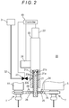
Fig. 2 is a front view of a schematic configuration of the tool changer, which shows a state where tools are attached to a spindle and a tool pot; -
Fig. 3 is a front view of the schematic configuration of the tool changer, which shows a state where the tools have been pulled out of the spindle and the tool pot; -
Fig. 4 is a plan view of a schematic configuration of a tool change arm; -
Fig. 5 is an illustration for explaining a rotational position of the tool change arm in a tool change operation; -
Fig. 6 is an illustration for explaining a rotational position of the tool change arm in the tool change operation; -
Fig. 7 is an illustration for explaining a rotational position of the tool change arm in the tool change operation; and -
Fig. 8 is an illustration for explaining a rotational position of the tool change arm in the tool change operation. - 0022 Hereinafter, a specific embodiment of the present invention will be described with reference to the drawings.
- 0023 As shown in
Fig. 1 , amachine tool 1 in this embodiment is a vertical machining center, and is composed of a bed 2, acolumn 3 erected on the bed 2, a spindle head 4 supported by thecolumn 3 to be moved in a vertical direction by an appropriate feed mechanism, aspindle 5 supported by the spindle head 4 to be rotatable about an axis thereof and rotated by an appropriate spindle motor incorporated in the spindle head 4, a table 6 disposed on the bed 2 below thespindle 5, atool magazine 10 disposed at a side of the spindle head 4, atool changer 20 provided on thetool magazine 10 for changing a tool T attached to thespindle 5 with a tool T' stored in atool pot 11 of thetool magazine 10, and acontroller 40 controlling operations of the above-mentioned components. - 0024 The
tool magazine 10 is composed of a plurality oftool pots 11 holding tools T', a circular plate-shapedholding plate 12 holding thetool pots 11 at regular intervals on an outer peripheral portion thereof, and acover body 13 surrounding thetool pots 11 and the holdingplate 12 and having anopening 13a formed in a lower portion thereof. Further, the holdingplate 12 is configured to be driven and rotated about a center axis thereof by an appropriate rotation drive mechanism (not shown), and, by rotating the holdingplate 12, one of thetool pots 11 held by the holdingplate 12 that holds a desired tool T' can be indexed to a position corresponding to theopening 13a of the cover body 13 (hereinafter, this position is referred to as "index position"). Further, thetool pot 11 indexed to the index position is turned in a vertical plane by an appropriate turning mechanism (not shown) to transfer it to a standby position at which thetool pot 11 is parallel to thespindle 5, and thetool pot 11 transferred to the standby position is similarly turned in a vertical plane by the turning mechanism to transfer it back to the index position. - 0025 Further, as shown in
Figs. 2 to 4 , thetool changer 20 is composed of asupport shaft 21 that is disposed midway between thespindle 5 and atool pot 11 transferred to the standby position to have an axis parallel to the axis of thespindle 5, a forward/backwardmovement drive motor 22 that is fixed to a top surface of ahousing 23 for moving thesupport shaft 21 upward and downward, arotation drive motor 24 that is fixed to a side surface of thehousing 23 for rotating thesupport shaft 21 about the axis thereof, atool change arm 25 that hastool grippers 27 formed at both ends thereof for gripping tools T and T' and is fixed to a lower end portion of thesupport shaft 21, and an air blow mechanism 30 that discharges compressed air fromair nozzles 34 provided on thetool change arm 25. Note that a mechanism that includes the forward/backwardmovement drive motor 22 and a ball screw (not shown) screwed with a rear end of the support shat 21 and moves thesupport shaft 21 upward or downward by rotating thesupport shaft 21 with the forward/backwardmovement drive motor 22 forms a forward/backward moving mechanism. Further, a mechanism that includes therotation drive motor 24 and a bevel gear mechanism (not shown) meshing with a spline (not shown) formed on an outer peripheral surface of the rear end side of thesupport shaft 21 and rotates thesupport shaft 21 about the axis thereof through the bevel gear mechanism by rotating therotation drive motor 24 forms a rotating mechanism. - 0026 The
support shaft 21 has agroove 21 b formed in an outer peripheral surface of an intermediate portion thereof, which is formed along a circumferential direction. Thesupport shaft 21 also has asupply channel 21 a formed therein, which is formed along the axis of thesupport shaft 21 and has two openings in an outer peripheral surface of a lower end portion of thesupport shaft 21. Note that thesupply channel 21 a and thegroove 21 b communicate with each other through asupply channel 21 c. - 0027 Further, the
housing 23 has arecess 23a formed in a portion of an inner peripheral surface thereof, which is formed along a circumferential direction. Thehousing 23 also has asupply channel 23b formed therein, which is open to a bottom surface of therecess 23a at one end and is open to an outer peripheral surface of thehousing 23 at the other end. Note that therecess 23a is formed to have a width greater than that of thegroove 21 b of thesupport shaft 21, and, under the state where thesupport shaft 21 is inserted in thehousing 23, thegroove 21 b and therecess 23a face each other and they consistently communicate with each other even during rotation of thesupport shaft 21. - 0028 A body of the
tool change arm 25 has a throughhole 25a formed therein, in which thesupport shaft 21 is inserted. The body of thetool change arm 25 also has twosupply channels 26 formed therein, which are open to a wall of the thoughhole 25a, extend from the wall of the throughhole 25a toward the ends of thetool change arm 25, and are open to an upper surface of the body of thetool change arm 25. Further, thetool change arm 25 is attached to thesupport shaft 21 in a state where thesupport shaft 21 is inserted in the throughhole 25a and thesupply channel 21 a communicates with thesupply channels 26 through the openings in the outer peripheral surface of thesupport shaft 21 and the openings in the wall of the thoughhole 25a. - 0029 Each of the
tool grippers 27 of thetool change arm 25 is composed of a fixedjaw 27a having an arcuate shape in plan view, and amovable jaw 27b supported by the body of thetool change arm 25 in a state of facing the fixedjaw 27a. When the tools T and T' are pulled out of thespindle 5 and thetool pot 11, themovable jaws 27b are fixed in a state where a predetermined gripping force is applied to the tools T and T' by the fixedjaws 27a and themovable jaws 27b. - 0030 The air blow mechanism 30 is composed of a
compressor 31 as a compressed air supply that supplies compressed air, asupply pipe 32 connected to thecompressor 31 at one end and connected to thesupply channel 23b formed in thehousing 23 at the other end, asolenoid valve 33 disposed in thesupply pipe 32 between thecompressor 31 and thesupply channel 23b, and theair nozzles 34 that are attached to the openings in the upper surface of the body of thetool change arm 25, the opening and closing of thesolenoid valve 33 being controlled by thecontroller 40. - 0031 In this air blow mechanism 30, by bringing the
solenoid valve 33 into an open state, compressed air is supplied from thecompressor 31 to theair nozzles 34 through thesupply pipe 32, thesupply channel 23b, therecess 23a, thegroove 21 b, thesupply channel 21 c, thesupply channel 21 a, and thesupply channels 26, and the compressed air is discharged from theair nozzles 34. Note that theair nozzles 34 are attached so that their discharge outlets are oriented so as to spray compressed air to at least tapered portions of the tools T and T' pulled out of thespindle 5 andtool pot 11. - 0032 Further, the
controller 40 controls the vertical movement of the spindle head 4 and the rotational movement of thespindle 5, and also controls operations of the forward/backwardmovement drive motor 22 and rotation drivemotor 24 and the opening and closing of thesolenoid valve 33. - 0033 Next, a sequence of tool change in the
machine tool 1 having the above-described configuration is described in detail with reference toFig. 3 andFigs. 5 to 8 . Note thatFigs. 5 to 8 show views of thetool change arm 25 seen from below. - 0034 In the
machine tool 1 in this embodiment, after a workpiece is machined by a tool T attached to thespindle 5 with thetool change arm 25 positioned at an original position (seeFig. 5 ), if a next tool T' that is of a different type from the tool T is used in the next machining, thespindle 5 together with the spindle head 4 are first moved to a position where the tool can be changed (tool change position). Further, as described above, thetool pot 11 holding the next tool T' is indexed to the index position by the appropriate rotation drive mechanism and then transferred to the standby position by the appropriate turning mechanism. - 0035 Subsequently, a gripping operation is performed. Specifically, the
rotation drive motor 24 is actuated to rotate thesupport shaft 21 by 90 degrees in the normal direction. Thereby, thetool change arm 25 is rotated about thesupport shaft 21 in the direction indicated by arrow inFig. 6 from the original position and is positioned at a gripping position that is located at a position rotated 90 degrees from the original position, and the tool T attached to thespindle 5 and the next tool T' transferred to the standby position are gripped by the tool grippers 27 (seeFig. 6 ). - 0036 Subsequently, the forward/backward
movement drive motor 22 is actuated to move thesupport shaft 21 downward. Thereby, as shown inFig. 4 , thetool change arm 25 is moved downward in a state of gripping the tool T and the next tool T' with thetool grippers 27, whereby the tools T and T' are pulled out of thespindle 5 and thetool pot 11, respectively (pulling operation). - 0037 Thereafter, a positioning operation is performed. That is, the
rotation drive motor 24 is actuated to rotate thesupport shaft 21 by (180+n×360) degrees in the normal direction, whereby thetool change arm 25 is rotated by (180+n×360) degrees in the same direction (the direction indicated by arrow inFig. 6 ). Thereby, the positions of the tool T and next tool T' are switched, that is, the next tool T' is moved to a position below thespindle 5 and the tool T is moved to a position below the tool pot 11 (seeFig. 7 ). - 0038 Thus, in performing the positioning operation, the
tool change arm 25 is intentionally rotated by (180+n×360) degrees, not by the minimum angle of rotation (180 degrees) needed for switching the positions of the tool T and next tool T', which allows chips and coolant adhering to the tools T and T' to be removed using a centrifugal force produced by the rotation of thetool change arm 25 simultaneously with the switching of the positions of the tool T and next tool T'. Note that the angle of rotation of the tool change arm 25 (in other words, the value of n) can be set to an appropriate value which does not excessively lengthen the tool change operation time, such as 540 degrees (n=1), 900 degrees (n=2), 1260 degrees (n=3), or the like. - 0039 Further, in the positioning operation, the
solenoid valve 33 is brought into the open state at a timing when the centrifugal force produced by the rotation of thetool change arm 25 becomes largest, that is, at a timing when the rotational speed of thetool change arm 25 becomes largest. Thereby, compressed air supplied from thecompressor 31 is discharged from theair nozzles 34 toward the tool T and the next tool T' (see the broken lines inFigs. 3 and6 ). This allows the tools to become subject not only to the action of the centrifugal force but also to the action of an air pressure of the compressed air discharged from the air nozzles; synergy between them enables a more effective removal of chips and coolant. - 0040 Note that examples of the manner of causing the
controller 40 to discharge compressed air at the timing when the rotational speed of thetool change arm 25 becomes largest includes a manner in which a rotational angular position at which the rotational speed of thetool change arm 25 becomes largest is previously obtained from an appropriate rotary encoder, which is provided on therotation drive motor 24, and stored in thecontroller 40 through a preliminary operation, and, when performing the tool change operation, thecontroller 40 receives a signal output from the rotary encoder and, at a timing when the received signal becomes the previously stored rotational angular position, brings thesolenoid value 33 into the open state to discharge compressed air from the air nozzles, and a manner in which, when performing the tool change operation, thecontroller 40 processes a signal output from the rotary encoder and detects a timing when acceleration of thetool change arm 25 becomes almost zero (that is, the rotational speed becomes largest), and, at the detected timing, brings thesolenoid valve 33 into the open state to discharge compressed air from the air nozzles. - 0041 Subsequently, an attaching operation is performed. Specifically, the forward/backward
movement drive motor 22 is actuated to move thesupport shaft 21 upward, thereby attaching the tool T to thetool pot 11 and attaching the next tool T' to thespindle 5. - 0042 Thereafter, for performing a returning operation, the
rotation drive motor 24 is actuated to rotate thesupport shaft 21 by 90 degrees in the reverse direction. Thereby, thetool change arm 25 is rotated by 90 degrees in the same direction (the direction indicated by arrow inFig. 7 ) from the gripping position and returned to the original position (seeFig. 8 ), and then the series of operations for tool change is ended. - 0043 After the tool change operation is ended, machining of the workpiece is resumed using the next tool T' attached to the
spindle 5. - 0044 As described above, according to the
machine tool 1 in this embodiment, thetool change arm 25 is rotated by (180+n×360) degrees in the positioning operation in the tool change operation; therefore, chips and coolant adhering to the tool T and next tool T' can be removed while minimizing influence on machining of a workpiece and preventing significant increase in machining time. - 0045 Thus, one embodiment of the present invention has been described above; however, the present invention is not limited thereto and can be implemented in other modes.
- 0046 For example, although, in the above embodiment, compressed air is discharged from the
air nozzles 34 at the timing when the rotational speed of thetool change arm 25 becomes largest in the positioning operation, compressed air may be, for example, continuously discharged or intermittently discharged during the positioning operation. Alternatively, compressed air may be continuously or intermittently discharged during the period of time from the pulling operation to the attaching operation. - 0047 Further, although, in the above embodiment, compressed air is supplied to the
air nozzles 34 attached to the upper surface of the body of thetool change arm 25 through thesupply channel 21 a formed in thesupport shaft 21 and thesupply channels 26 formed in the body of thetool change arm 25, the manner in which compressed air is supplied is not limited thereto. For example, an embodiment is possible in which air nozzles are attached to an outer peripheral surface of thesupport shaft 21 and a supply channel for supplying compressed air to the air nozzles is formed in thesupport shaft 21. Also in this embodiment, compressed air can be discharged toward the tools T and T' gripped by thetool grippers 27. - 0048 Further, the air blow mechanism 30 is not necessarily provided, and adhering chips and coolant may be removed only by the action of the centrifugal force produced by the rotation of the
tool change arm 25. - 0049 Furthermore, although, in the above embodiment, the vertical movement of the
support shaft 21 is performed with the forward/backwardmovement drive motor 22 and the rotation of thesupport shaft 21 is performed with therotation drive motor 24, the present invention is not limited thereto. An embodiment is possible in which a support shaft is connected to a single drive motor through an appropriate cam mechanism and the support shaft is moved upward and downward or rotated by rotating the drive motor and transmitting a rotational power to the cam mechanism. - 0050 Further, in the above embodiment, the tool T positioned at the tool change position and the next tool T' positioned at the standby position are swung into the
tool grippers 27 by rotating thetool change arm 25 from the original position, whereby the tools T and T' are gripped. However, for example, an H-shaped tool change arm may be employed instead of an S-shaped one, in which case two tool grippers of the tool change arm are positioned at a tool change position and a standby position in advance and thespindle 5 and thetool pot 11 are moved toward thetool grippers 27. - 0051
- 1
- Machine tool
- 2
- Bed
- 3
- Column
- 4
- Spindle head
- 5
- Spindle
- 6
- Table
- 10
- Tool magazine
- 11
- Tool pot
- 20
- Tool changer
- 21
- Support shaft
- 21a
- Supply channel
- 22
- Forward/backward movement drive motor
- 24
- Rotation drive motor
- 25
- Tool change arm
- 26
- Supply channel
- 27
- Tool gripper
- 30
- Air blow mechanism
- 31
- Compressor
- 32
- Supply pipe
- 33
- Solenoid valve
- 34
- Air nozzle
- 40
- Controller
Claims (4)
- A method of changing a tool attached to a spindle of a machine tool with a next tool positioned at a standby position by using a tool change arm having a tool gripper at each of both ends thereof and provided to be rotated about an axis of a support shaft disposed parallel to the spindle of the machine tool and to be moved forward and backward along a direction of the axis of the support shaft,
the tool attached to the spindle of the machine tool being changed with the next tool positioned at the standby position by executing:a gripping operation of rotating the tool change arm about the axis of the support shaft from an original position so as to cause one of the tool grippers to grip the tool attached to the spindle and cause the other of the tool grippers to grip the next tool positioned at the standby position;a pulling operation of moving the tool change arm forward along the support shaft so as to pull the tool out of the spindle,a positioning operation of rotating the tool change arm about the axis of the support shaft so as to position the next tool gripped by the other of the tool grippers on an axis of the spindle;an attaching operation of moving the tool change arm backward along the support shaft so as to attach the next tool gripped by the other of the tool grippers to the spindle; anda returning operation of rotating the tool change arm about the axis of the support shaft so as to return the tool change arm to the original position, characterized in thatthe tool change arm is rotated by (180+n×360) degrees in the positioning operation, n being a positive integer. - A tool changer disposed at a tool change position in a machine tool for changing a tool attached to a spindle with a next tool positioned at a standby position, comprising:a tool change arm having a tool gripper at each of both ends thereof;a support shaft provided parallel to the spindle for supporting the tool change arm;a rotating mechanism rotating the tool change arm about an axis of the support shaft; anda forward/backward moving mechanism moving the tool change arm forward and backward along the support shaft,the tool changer being configured to perform:a gripping operation of causing the rotating mechanism to rotate the tool change arm about the axis of the support shaft from an original position so as to cause one of the tool grippers to grip the tool attached to the spindle and cause the other of the tool grippers to grip the next tool positioned at the standby position;a pulling operation of causing the forward/backward moving mechanism to move the tool change arm forward along the support shaft so as to pull the tool out of the spindle;a positioning operation of causing the rotating mechanism to rotate the tool change arm about the axis of the support shaft so as to position the tool gripped by the other of the tool grippers on an axis of the spindle;an attaching operation of causing the forward/backward moving mechanism to move the tool change arm backward along the support shaft so as to attach the next tool gripped by the other of the tool grippers to the spindle; anda returning operation of causing the rotating mechanism to rotate the tool change arm about the axis of the support shaft so as to return the tool change arm to the original position, characterized in thatthe rotating mechanism rotates the tool change arm by (180+n×360) degrees when performing the positioning operation, n being a positive integer.
- The tool changer according to claim 2, characterized in that
the tool changer further comprises an air blow mechanism including a discharge nozzle discharging compressed air, a compressed air supply supplying compressed air, a supply channel connected to the discharge nozzle and the compressed air supply for supplying compressed air to the discharge nozzle, and
the discharge nozzle is disposed to discharge compressed air toward the tools gripped by the tool grippers of the tool change arm. - The tool changer according to claim 3, characterized in that the discharge nozzle is disposed on the support shaft or the tool change arm.
Applications Claiming Priority (2)
| Application Number | Priority Date | Filing Date | Title |
|---|---|---|---|
| JP2014171403A JP6279432B2 (en) | 2014-08-26 | 2014-08-26 | Tool changing method and tool changing device |
| PCT/JP2015/062067 WO2016031298A1 (en) | 2014-08-26 | 2015-04-21 | Tool changing method and tool changing device |
Publications (3)
| Publication Number | Publication Date |
|---|---|
| EP3187301A1 true EP3187301A1 (en) | 2017-07-05 |
| EP3187301A4 EP3187301A4 (en) | 2018-05-02 |
| EP3187301B1 EP3187301B1 (en) | 2019-10-16 |
Family
ID=55399204
Family Applications (1)
| Application Number | Title | Priority Date | Filing Date |
|---|---|---|---|
| EP15835275.7A Active EP3187301B1 (en) | 2014-08-26 | 2015-04-21 | Tool changing method and tool changing device |
Country Status (5)
| Country | Link |
|---|---|
| US (1) | US10252385B2 (en) |
| EP (1) | EP3187301B1 (en) |
| JP (1) | JP6279432B2 (en) |
| CN (1) | CN106232291B (en) |
| WO (1) | WO2016031298A1 (en) |
Cited By (1)
| Publication number | Priority date | Publication date | Assignee | Title |
|---|---|---|---|---|
| CN111844479A (en) * | 2020-07-06 | 2020-10-30 | 薛燕芬 | Cutting machine for hard materials |
Families Citing this family (11)
| Publication number | Priority date | Publication date | Assignee | Title |
|---|---|---|---|---|
| JP6746429B2 (en) * | 2016-08-17 | 2020-08-26 | Dmg森精機株式会社 | Tool changer |
| CN106078304A (en) * | 2016-08-19 | 2016-11-09 | 宁波金凯机床股份有限公司 | A kind of lathe tool changing device |
| KR102632892B1 (en) * | 2017-01-19 | 2024-02-06 | 주식회사 디엔솔루션즈 | Unit for receiving a tool and hybrid machine tool including the same |
| TWI655993B (en) * | 2018-07-06 | 2019-04-11 | 聖杰國際股份有限公司 | Shaft rotation and linear displacement control system and automatic tool change mechanism having the same |
| TWI650201B (en) * | 2018-07-06 | 2019-02-11 | 聖杰國際股份有限公司 | Tool change control method of automatic tool change mechanism |
| JP7029491B2 (en) * | 2020-07-07 | 2022-03-03 | Dmg森精機株式会社 | Machine tools, machine tool control methods, and machine tool control programs |
| US20220143767A1 (en) * | 2020-11-06 | 2022-05-12 | Deta International Co., Ltd. | Tool Changing Method For Machine Tool and Tool Changing Apparatus Thereof |
| CN116940439A (en) * | 2021-03-01 | 2023-10-24 | Dmg森精机株式会社 | Tool conveying device |
| CN113909981B (en) * | 2021-09-29 | 2023-03-28 | 方冠(常州)数控科技有限公司 | A manipulator assembly for unloading in automation |
| KR102634801B1 (en) * | 2021-11-25 | 2024-02-08 | 현대위아 주식회사 | Automatic Tool Changer |
| CN121444030A (en) * | 2023-11-07 | 2026-01-30 | 三菱电机株式会社 | CNC devices and CNC methods |
Family Cites Families (20)
| Publication number | Priority date | Publication date | Assignee | Title |
|---|---|---|---|---|
| US3691626A (en) * | 1970-09-10 | 1972-09-19 | Gorton Machine Corp | Tool change mechanism |
| JPS6322667U (en) * | 1986-07-21 | 1988-02-15 | ||
| JPS63123646A (en) * | 1986-11-12 | 1988-05-27 | Brother Ind Ltd | Machine tool with tool changer |
| JPS63131342A (en) | 1986-11-20 | 1988-06-03 | Canon Inc | optical card |
| JPS63131342U (en) * | 1987-02-20 | 1988-08-26 | ||
| US5353823A (en) * | 1989-09-29 | 1994-10-11 | Starrfras Maschinen AG | Device for cleaning the fastening shank of a tool or of a toolholder |
| JPH0577129A (en) * | 1991-04-19 | 1993-03-30 | Akihiko Makabe | Tool exchanging method for wet type machine tool using rotary tool |
| DE19702974A1 (en) * | 1997-01-28 | 1998-07-30 | Chiron Werke Gmbh | Machine tool with a flushing device |
| JPH11138377A (en) * | 1997-11-13 | 1999-05-25 | Toshiba Mach Co Ltd | Automatic tool replacement device |
| JP2001162483A (en) * | 1999-12-03 | 2001-06-19 | Brother Ind Ltd | Machine tool with tool changer |
| US6490941B1 (en) * | 2000-03-28 | 2002-12-10 | Sung Hur | Elliptic motion driving apparatus for a step screen |
| JP4531197B2 (en) * | 2000-05-08 | 2010-08-25 | 株式会社森精機製作所 | Automatic tool changer |
| JP3877560B2 (en) * | 2001-09-21 | 2007-02-07 | 株式会社牧野フライス製作所 | Automatic tool changer |
| JP4145557B2 (en) * | 2002-04-24 | 2008-09-03 | 東芝機械株式会社 | Automatic tool changer having spindle end face cleaning function and sequence control device thereof |
| JP3764432B2 (en) * | 2003-03-06 | 2006-04-05 | ファナック株式会社 | Tool chip prevention / removal method and tool changer |
| JP3761545B2 (en) * | 2003-07-07 | 2006-03-29 | ファナック株式会社 | Automatic tool changer for machine tools |
| JP3929424B2 (en) * | 2003-08-06 | 2007-06-13 | ファナック株式会社 | Tool changer and tool cleaning method |
| DE102005043602B4 (en) * | 2005-09-12 | 2018-07-26 | Reishauer Ag | Gear processing machine and method for operating such a gear processing machine |
| JP5265963B2 (en) * | 2008-05-16 | 2013-08-14 | オークマ株式会社 | Machine Tools |
| CN203253937U (en) * | 2013-05-28 | 2013-10-30 | 浙江日发精密机械股份有限公司 | Spindle mechanism |
-
2014
- 2014-08-26 JP JP2014171403A patent/JP6279432B2/en not_active Expired - Fee Related
-
2015
- 2015-04-21 WO PCT/JP2015/062067 patent/WO2016031298A1/en not_active Ceased
- 2015-04-21 EP EP15835275.7A patent/EP3187301B1/en active Active
- 2015-04-21 US US15/325,129 patent/US10252385B2/en active Active
- 2015-04-21 CN CN201580021438.0A patent/CN106232291B/en not_active Expired - Fee Related
Cited By (1)
| Publication number | Priority date | Publication date | Assignee | Title |
|---|---|---|---|---|
| CN111844479A (en) * | 2020-07-06 | 2020-10-30 | 薛燕芬 | Cutting machine for hard materials |
Also Published As
| Publication number | Publication date |
|---|---|
| CN106232291A (en) | 2016-12-14 |
| WO2016031298A1 (en) | 2016-03-03 |
| EP3187301B1 (en) | 2019-10-16 |
| EP3187301A4 (en) | 2018-05-02 |
| JP2016043466A (en) | 2016-04-04 |
| US10252385B2 (en) | 2019-04-09 |
| JP6279432B2 (en) | 2018-02-14 |
| CN106232291B (en) | 2019-06-18 |
| US20170190008A1 (en) | 2017-07-06 |
Similar Documents
| Publication | Publication Date | Title |
|---|---|---|
| EP3187301B1 (en) | Tool changing method and tool changing device | |
| CN104159704B (en) | Rotary processor and rotation processing method | |
| US9522433B2 (en) | Rotation processing machine | |
| JP5024832B2 (en) | Automatic tool changer | |
| CN111093893B (en) | Machine tool system | |
| JP2009012175A (en) | Method and device for machining workpiece rotating around workpiece axis | |
| CN108655802B (en) | Machine tool system and moving method | |
| KR20150136485A (en) | Polygon machining device and polygon machining method | |
| JP5538012B2 (en) | Machine Tools | |
| KR20060050784A (en) | Vertical lathe | |
| RU2751951C2 (en) | Turning machine and method of turning workpieces | |
| US20180354089A1 (en) | Machine tool for machining a workpiece | |
| KR100405797B1 (en) | Automatic tool exchanging apparatus | |
| TWM452030U (en) | Machine tool | |
| JP5246570B2 (en) | Tool change method and tool change device | |
| WO2015041084A1 (en) | Rod-material supplying device and numerical controlled machine tool equipped with rod-material supplying device | |
| US10850387B2 (en) | Automatic workpiece transfer machine | |
| JP3134196U (en) | Lathe machine and loading device | |
| JP2006110716A (en) | Multi-face processing machine and workpiece positioning device | |
| JP7495786B2 (en) | Continuous machining using a robot table that tracks fixtures | |
| JP2003311504A (en) | Work transfer method in-lathe | |
| WO2006018009A3 (en) | Tool changing system for a machine tool | |
| JP2008073786A (en) | Cutting jig and cutting method | |
| JP2009006419A (en) | Workpiece paying-out device of horizontal machining center | |
| JPS63251143A (en) | Machining center |
Legal Events
| Date | Code | Title | Description |
|---|---|---|---|
| STAA | Information on the status of an ep patent application or granted ep patent |
Free format text: STATUS: THE INTERNATIONAL PUBLICATION HAS BEEN MADE |
|
| PUAI | Public reference made under article 153(3) epc to a published international application that has entered the european phase |
Free format text: ORIGINAL CODE: 0009012 |
|
| STAA | Information on the status of an ep patent application or granted ep patent |
Free format text: STATUS: REQUEST FOR EXAMINATION WAS MADE |
|
| 17P | Request for examination filed |
Effective date: 20170207 |
|
| AK | Designated contracting states |
Kind code of ref document: A1 Designated state(s): AL AT BE BG CH CY CZ DE DK EE ES FI FR GB GR HR HU IE IS IT LI LT LU LV MC MK MT NL NO PL PT RO RS SE SI SK SM TR |
|
| AX | Request for extension of the european patent |
Extension state: BA ME |
|
| DAV | Request for validation of the european patent (deleted) | ||
| DAX | Request for extension of the european patent (deleted) | ||
| A4 | Supplementary search report drawn up and despatched |
Effective date: 20180403 |
|
| RIC1 | Information provided on ipc code assigned before grant |
Ipc: B23Q 11/00 20060101ALI20180326BHEP Ipc: B23Q 3/157 20060101ALI20180326BHEP Ipc: B23Q 3/155 20060101AFI20180326BHEP |
|
| GRAP | Despatch of communication of intention to grant a patent |
Free format text: ORIGINAL CODE: EPIDOSNIGR1 |
|
| STAA | Information on the status of an ep patent application or granted ep patent |
Free format text: STATUS: GRANT OF PATENT IS INTENDED |
|
| INTG | Intention to grant announced |
Effective date: 20190514 |
|
| GRAS | Grant fee paid |
Free format text: ORIGINAL CODE: EPIDOSNIGR3 |
|
| GRAA | (expected) grant |
Free format text: ORIGINAL CODE: 0009210 |
|
| STAA | Information on the status of an ep patent application or granted ep patent |
Free format text: STATUS: THE PATENT HAS BEEN GRANTED |
|
| AK | Designated contracting states |
Kind code of ref document: B1 Designated state(s): AL AT BE BG CH CY CZ DE DK EE ES FI FR GB GR HR HU IE IS IT LI LT LU LV MC MK MT NL NO PL PT RO RS SE SI SK SM TR |
|
| REG | Reference to a national code |
Ref country code: GB Ref legal event code: FG4D |
|
| REG | Reference to a national code |
Ref country code: CH Ref legal event code: EP |
|
| REG | Reference to a national code |
Ref country code: DE Ref legal event code: R096 Ref document number: 602015040028 Country of ref document: DE |
|
| REG | Reference to a national code |
Ref country code: IE Ref legal event code: FG4D |
|
| REG | Reference to a national code |
Ref country code: AT Ref legal event code: REF Ref document number: 1190820 Country of ref document: AT Kind code of ref document: T Effective date: 20191115 |
|
| REG | Reference to a national code |
Ref country code: NL Ref legal event code: MP Effective date: 20191016 |
|
| REG | Reference to a national code |
Ref country code: LT Ref legal event code: MG4D |
|
| REG | Reference to a national code |
Ref country code: AT Ref legal event code: MK05 Ref document number: 1190820 Country of ref document: AT Kind code of ref document: T Effective date: 20191016 |
|
| PG25 | Lapsed in a contracting state [announced via postgrant information from national office to epo] |
Ref country code: PT Free format text: LAPSE BECAUSE OF FAILURE TO SUBMIT A TRANSLATION OF THE DESCRIPTION OR TO PAY THE FEE WITHIN THE PRESCRIBED TIME-LIMIT Effective date: 20200217 Ref country code: FI Free format text: LAPSE BECAUSE OF FAILURE TO SUBMIT A TRANSLATION OF THE DESCRIPTION OR TO PAY THE FEE WITHIN THE PRESCRIBED TIME-LIMIT Effective date: 20191016 Ref country code: BG Free format text: LAPSE BECAUSE OF FAILURE TO SUBMIT A TRANSLATION OF THE DESCRIPTION OR TO PAY THE FEE WITHIN THE PRESCRIBED TIME-LIMIT Effective date: 20200116 Ref country code: GR Free format text: LAPSE BECAUSE OF FAILURE TO SUBMIT A TRANSLATION OF THE DESCRIPTION OR TO PAY THE FEE WITHIN THE PRESCRIBED TIME-LIMIT Effective date: 20200117 Ref country code: PL Free format text: LAPSE BECAUSE OF FAILURE TO SUBMIT A TRANSLATION OF THE DESCRIPTION OR TO PAY THE FEE WITHIN THE PRESCRIBED TIME-LIMIT Effective date: 20191016 Ref country code: NO Free format text: LAPSE BECAUSE OF FAILURE TO SUBMIT A TRANSLATION OF THE DESCRIPTION OR TO PAY THE FEE WITHIN THE PRESCRIBED TIME-LIMIT Effective date: 20200116 Ref country code: SE Free format text: LAPSE BECAUSE OF FAILURE TO SUBMIT A TRANSLATION OF THE DESCRIPTION OR TO PAY THE FEE WITHIN THE PRESCRIBED TIME-LIMIT Effective date: 20191016 Ref country code: LV Free format text: LAPSE BECAUSE OF FAILURE TO SUBMIT A TRANSLATION OF THE DESCRIPTION OR TO PAY THE FEE WITHIN THE PRESCRIBED TIME-LIMIT Effective date: 20191016 Ref country code: AT Free format text: LAPSE BECAUSE OF FAILURE TO SUBMIT A TRANSLATION OF THE DESCRIPTION OR TO PAY THE FEE WITHIN THE PRESCRIBED TIME-LIMIT Effective date: 20191016 Ref country code: LT Free format text: LAPSE BECAUSE OF FAILURE TO SUBMIT A TRANSLATION OF THE DESCRIPTION OR TO PAY THE FEE WITHIN THE PRESCRIBED TIME-LIMIT Effective date: 20191016 Ref country code: NL Free format text: LAPSE BECAUSE OF FAILURE TO SUBMIT A TRANSLATION OF THE DESCRIPTION OR TO PAY THE FEE WITHIN THE PRESCRIBED TIME-LIMIT Effective date: 20191016 |
|
| PG25 | Lapsed in a contracting state [announced via postgrant information from national office to epo] |
Ref country code: IS Free format text: LAPSE BECAUSE OF FAILURE TO SUBMIT A TRANSLATION OF THE DESCRIPTION OR TO PAY THE FEE WITHIN THE PRESCRIBED TIME-LIMIT Effective date: 20200224 Ref country code: RS Free format text: LAPSE BECAUSE OF FAILURE TO SUBMIT A TRANSLATION OF THE DESCRIPTION OR TO PAY THE FEE WITHIN THE PRESCRIBED TIME-LIMIT Effective date: 20191016 Ref country code: HR Free format text: LAPSE BECAUSE OF FAILURE TO SUBMIT A TRANSLATION OF THE DESCRIPTION OR TO PAY THE FEE WITHIN THE PRESCRIBED TIME-LIMIT Effective date: 20191016 |
|
| PG25 | Lapsed in a contracting state [announced via postgrant information from national office to epo] |
Ref country code: AL Free format text: LAPSE BECAUSE OF FAILURE TO SUBMIT A TRANSLATION OF THE DESCRIPTION OR TO PAY THE FEE WITHIN THE PRESCRIBED TIME-LIMIT Effective date: 20191016 |
|
| REG | Reference to a national code |
Ref country code: DE Ref legal event code: R097 Ref document number: 602015040028 Country of ref document: DE |
|
| PG2D | Information on lapse in contracting state deleted |
Ref country code: IS |
|
| PG25 | Lapsed in a contracting state [announced via postgrant information from national office to epo] |
Ref country code: DK Free format text: LAPSE BECAUSE OF FAILURE TO SUBMIT A TRANSLATION OF THE DESCRIPTION OR TO PAY THE FEE WITHIN THE PRESCRIBED TIME-LIMIT Effective date: 20191016 Ref country code: ES Free format text: LAPSE BECAUSE OF FAILURE TO SUBMIT A TRANSLATION OF THE DESCRIPTION OR TO PAY THE FEE WITHIN THE PRESCRIBED TIME-LIMIT Effective date: 20191016 Ref country code: EE Free format text: LAPSE BECAUSE OF FAILURE TO SUBMIT A TRANSLATION OF THE DESCRIPTION OR TO PAY THE FEE WITHIN THE PRESCRIBED TIME-LIMIT Effective date: 20191016 Ref country code: RO Free format text: LAPSE BECAUSE OF FAILURE TO SUBMIT A TRANSLATION OF THE DESCRIPTION OR TO PAY THE FEE WITHIN THE PRESCRIBED TIME-LIMIT Effective date: 20191016 Ref country code: CZ Free format text: LAPSE BECAUSE OF FAILURE TO SUBMIT A TRANSLATION OF THE DESCRIPTION OR TO PAY THE FEE WITHIN THE PRESCRIBED TIME-LIMIT Effective date: 20191016 Ref country code: IS Free format text: LAPSE BECAUSE OF FAILURE TO SUBMIT A TRANSLATION OF THE DESCRIPTION OR TO PAY THE FEE WITHIN THE PRESCRIBED TIME-LIMIT Effective date: 20200216 |
|
| PLBE | No opposition filed within time limit |
Free format text: ORIGINAL CODE: 0009261 |
|
| STAA | Information on the status of an ep patent application or granted ep patent |
Free format text: STATUS: NO OPPOSITION FILED WITHIN TIME LIMIT |
|
| PG25 | Lapsed in a contracting state [announced via postgrant information from national office to epo] |
Ref country code: SM Free format text: LAPSE BECAUSE OF FAILURE TO SUBMIT A TRANSLATION OF THE DESCRIPTION OR TO PAY THE FEE WITHIN THE PRESCRIBED TIME-LIMIT Effective date: 20191016 Ref country code: SK Free format text: LAPSE BECAUSE OF FAILURE TO SUBMIT A TRANSLATION OF THE DESCRIPTION OR TO PAY THE FEE WITHIN THE PRESCRIBED TIME-LIMIT Effective date: 20191016 Ref country code: IT Free format text: LAPSE BECAUSE OF FAILURE TO SUBMIT A TRANSLATION OF THE DESCRIPTION OR TO PAY THE FEE WITHIN THE PRESCRIBED TIME-LIMIT Effective date: 20191016 |
|
| 26N | No opposition filed |
Effective date: 20200717 |
|
| PG25 | Lapsed in a contracting state [announced via postgrant information from national office to epo] |
Ref country code: MC Free format text: LAPSE BECAUSE OF FAILURE TO SUBMIT A TRANSLATION OF THE DESCRIPTION OR TO PAY THE FEE WITHIN THE PRESCRIBED TIME-LIMIT Effective date: 20191016 Ref country code: SI Free format text: LAPSE BECAUSE OF FAILURE TO SUBMIT A TRANSLATION OF THE DESCRIPTION OR TO PAY THE FEE WITHIN THE PRESCRIBED TIME-LIMIT Effective date: 20191016 |
|
| REG | Reference to a national code |
Ref country code: CH Ref legal event code: PL |
|
| PG25 | Lapsed in a contracting state [announced via postgrant information from national office to epo] |
Ref country code: CH Free format text: LAPSE BECAUSE OF NON-PAYMENT OF DUE FEES Effective date: 20200430 Ref country code: LU Free format text: LAPSE BECAUSE OF NON-PAYMENT OF DUE FEES Effective date: 20200421 Ref country code: LI Free format text: LAPSE BECAUSE OF NON-PAYMENT OF DUE FEES Effective date: 20200430 Ref country code: FR Free format text: LAPSE BECAUSE OF NON-PAYMENT OF DUE FEES Effective date: 20200430 |
|
| REG | Reference to a national code |
Ref country code: BE Ref legal event code: MM Effective date: 20200430 |
|
| PG25 | Lapsed in a contracting state [announced via postgrant information from national office to epo] |
Ref country code: BE Free format text: LAPSE BECAUSE OF NON-PAYMENT OF DUE FEES Effective date: 20200430 |
|
| GBPC | Gb: european patent ceased through non-payment of renewal fee |
Effective date: 20200421 |
|
| PG25 | Lapsed in a contracting state [announced via postgrant information from national office to epo] |
Ref country code: GB Free format text: LAPSE BECAUSE OF NON-PAYMENT OF DUE FEES Effective date: 20200421 Ref country code: IE Free format text: LAPSE BECAUSE OF NON-PAYMENT OF DUE FEES Effective date: 20200421 |
|
| PG25 | Lapsed in a contracting state [announced via postgrant information from national office to epo] |
Ref country code: TR Free format text: LAPSE BECAUSE OF FAILURE TO SUBMIT A TRANSLATION OF THE DESCRIPTION OR TO PAY THE FEE WITHIN THE PRESCRIBED TIME-LIMIT Effective date: 20191016 Ref country code: MT Free format text: LAPSE BECAUSE OF FAILURE TO SUBMIT A TRANSLATION OF THE DESCRIPTION OR TO PAY THE FEE WITHIN THE PRESCRIBED TIME-LIMIT Effective date: 20191016 Ref country code: CY Free format text: LAPSE BECAUSE OF FAILURE TO SUBMIT A TRANSLATION OF THE DESCRIPTION OR TO PAY THE FEE WITHIN THE PRESCRIBED TIME-LIMIT Effective date: 20191016 |
|
| PG25 | Lapsed in a contracting state [announced via postgrant information from national office to epo] |
Ref country code: MK Free format text: LAPSE BECAUSE OF FAILURE TO SUBMIT A TRANSLATION OF THE DESCRIPTION OR TO PAY THE FEE WITHIN THE PRESCRIBED TIME-LIMIT Effective date: 20191016 |
|
| PGFP | Annual fee paid to national office [announced via postgrant information from national office to epo] |
Ref country code: DE Payment date: 20240418 Year of fee payment: 10 |
|
| REG | Reference to a national code |
Ref country code: DE Ref legal event code: R119 Ref document number: 602015040028 Country of ref document: DE |
|
| PG25 | Lapsed in a contracting state [announced via postgrant information from national office to epo] |
Ref country code: DE Free format text: LAPSE BECAUSE OF NON-PAYMENT OF DUE FEES Effective date: 20251104 |