EP3187242A1 - Co2 recovery device and co2 recovery method - Google Patents
Co2 recovery device and co2 recovery method Download PDFInfo
- Publication number
- EP3187242A1 EP3187242A1 EP15819384.7A EP15819384A EP3187242A1 EP 3187242 A1 EP3187242 A1 EP 3187242A1 EP 15819384 A EP15819384 A EP 15819384A EP 3187242 A1 EP3187242 A1 EP 3187242A1
- Authority
- EP
- European Patent Office
- Prior art keywords
- recovery
- amount
- absorbing solution
- control unit
- recovery rate
- Prior art date
- Legal status (The legal status is an assumption and is not a legal conclusion. Google has not performed a legal analysis and makes no representation as to the accuracy of the status listed.)
- Granted
Links
Images
Classifications
-
- B—PERFORMING OPERATIONS; TRANSPORTING
- B01—PHYSICAL OR CHEMICAL PROCESSES OR APPARATUS IN GENERAL
- B01D—SEPARATION
- B01D53/00—Separation of gases or vapours; Recovering vapours of volatile solvents from gases; Chemical or biological purification of waste gases, e.g. engine exhaust gases, smoke, fumes, flue gases, aerosols
- B01D53/14—Separation of gases or vapours; Recovering vapours of volatile solvents from gases; Chemical or biological purification of waste gases, e.g. engine exhaust gases, smoke, fumes, flue gases, aerosols by absorption
- B01D53/1412—Controlling the absorption process
-
- B—PERFORMING OPERATIONS; TRANSPORTING
- B01—PHYSICAL OR CHEMICAL PROCESSES OR APPARATUS IN GENERAL
- B01D—SEPARATION
- B01D53/00—Separation of gases or vapours; Recovering vapours of volatile solvents from gases; Chemical or biological purification of waste gases, e.g. engine exhaust gases, smoke, fumes, flue gases, aerosols
- B01D53/14—Separation of gases or vapours; Recovering vapours of volatile solvents from gases; Chemical or biological purification of waste gases, e.g. engine exhaust gases, smoke, fumes, flue gases, aerosols by absorption
- B01D53/1425—Regeneration of liquid absorbents
-
- B—PERFORMING OPERATIONS; TRANSPORTING
- B01—PHYSICAL OR CHEMICAL PROCESSES OR APPARATUS IN GENERAL
- B01D—SEPARATION
- B01D53/00—Separation of gases or vapours; Recovering vapours of volatile solvents from gases; Chemical or biological purification of waste gases, e.g. engine exhaust gases, smoke, fumes, flue gases, aerosols
- B01D53/14—Separation of gases or vapours; Recovering vapours of volatile solvents from gases; Chemical or biological purification of waste gases, e.g. engine exhaust gases, smoke, fumes, flue gases, aerosols by absorption
- B01D53/1456—Removing acid components
- B01D53/1475—Removing carbon dioxide
-
- B—PERFORMING OPERATIONS; TRANSPORTING
- B01—PHYSICAL OR CHEMICAL PROCESSES OR APPARATUS IN GENERAL
- B01D—SEPARATION
- B01D53/00—Separation of gases or vapours; Recovering vapours of volatile solvents from gases; Chemical or biological purification of waste gases, e.g. engine exhaust gases, smoke, fumes, flue gases, aerosols
- B01D53/14—Separation of gases or vapours; Recovering vapours of volatile solvents from gases; Chemical or biological purification of waste gases, e.g. engine exhaust gases, smoke, fumes, flue gases, aerosols by absorption
- B01D53/18—Absorbing units; Liquid distributors therefor
-
- B—PERFORMING OPERATIONS; TRANSPORTING
- B01—PHYSICAL OR CHEMICAL PROCESSES OR APPARATUS IN GENERAL
- B01D—SEPARATION
- B01D53/00—Separation of gases or vapours; Recovering vapours of volatile solvents from gases; Chemical or biological purification of waste gases, e.g. engine exhaust gases, smoke, fumes, flue gases, aerosols
- B01D53/34—Chemical or biological purification of waste gases
- B01D53/346—Controlling the process
-
- B—PERFORMING OPERATIONS; TRANSPORTING
- B01—PHYSICAL OR CHEMICAL PROCESSES OR APPARATUS IN GENERAL
- B01D—SEPARATION
- B01D53/00—Separation of gases or vapours; Recovering vapours of volatile solvents from gases; Chemical or biological purification of waste gases, e.g. engine exhaust gases, smoke, fumes, flue gases, aerosols
- B01D53/34—Chemical or biological purification of waste gases
- B01D53/46—Removing components of defined structure
- B01D53/62—Carbon oxides
-
- B—PERFORMING OPERATIONS; TRANSPORTING
- B01—PHYSICAL OR CHEMICAL PROCESSES OR APPARATUS IN GENERAL
- B01D—SEPARATION
- B01D53/00—Separation of gases or vapours; Recovering vapours of volatile solvents from gases; Chemical or biological purification of waste gases, e.g. engine exhaust gases, smoke, fumes, flue gases, aerosols
- B01D53/34—Chemical or biological purification of waste gases
- B01D53/74—General processes for purification of waste gases; Apparatus or devices specially adapted therefor
- B01D53/77—Liquid phase processes
- B01D53/78—Liquid phase processes with gas-liquid contact
-
- F—MECHANICAL ENGINEERING; LIGHTING; HEATING; WEAPONS; BLASTING
- F23—COMBUSTION APPARATUS; COMBUSTION PROCESSES
- F23J—REMOVAL OR TREATMENT OF COMBUSTION PRODUCTS OR COMBUSTION RESIDUES; FLUES
- F23J15/00—Arrangements of devices for treating smoke or fumes
- F23J15/02—Arrangements of devices for treating smoke or fumes of purifiers, e.g. for removing noxious material
- F23J15/04—Arrangements of devices for treating smoke or fumes of purifiers, e.g. for removing noxious material using washing fluids
-
- B—PERFORMING OPERATIONS; TRANSPORTING
- B01—PHYSICAL OR CHEMICAL PROCESSES OR APPARATUS IN GENERAL
- B01D—SEPARATION
- B01D2252/00—Absorbents, i.e. solvents and liquid materials for gas absorption
- B01D2252/20—Organic absorbents
- B01D2252/204—Amines
- B01D2252/20478—Alkanolamines
-
- B—PERFORMING OPERATIONS; TRANSPORTING
- B01—PHYSICAL OR CHEMICAL PROCESSES OR APPARATUS IN GENERAL
- B01D—SEPARATION
- B01D2256/00—Main component in the product gas stream after treatment
- B01D2256/22—Carbon dioxide
-
- B—PERFORMING OPERATIONS; TRANSPORTING
- B01—PHYSICAL OR CHEMICAL PROCESSES OR APPARATUS IN GENERAL
- B01D—SEPARATION
- B01D2258/00—Sources of waste gases
- B01D2258/02—Other waste gases
- B01D2258/0283—Flue gases
-
- Y—GENERAL TAGGING OF NEW TECHNOLOGICAL DEVELOPMENTS; GENERAL TAGGING OF CROSS-SECTIONAL TECHNOLOGIES SPANNING OVER SEVERAL SECTIONS OF THE IPC; TECHNICAL SUBJECTS COVERED BY FORMER USPC CROSS-REFERENCE ART COLLECTIONS [XRACs] AND DIGESTS
- Y02—TECHNOLOGIES OR APPLICATIONS FOR MITIGATION OR ADAPTATION AGAINST CLIMATE CHANGE
- Y02A—TECHNOLOGIES FOR ADAPTATION TO CLIMATE CHANGE
- Y02A50/00—TECHNOLOGIES FOR ADAPTATION TO CLIMATE CHANGE in human health protection, e.g. against extreme weather
- Y02A50/20—Air quality improvement or preservation, e.g. vehicle emission control or emission reduction by using catalytic converters
-
- Y—GENERAL TAGGING OF NEW TECHNOLOGICAL DEVELOPMENTS; GENERAL TAGGING OF CROSS-SECTIONAL TECHNOLOGIES SPANNING OVER SEVERAL SECTIONS OF THE IPC; TECHNICAL SUBJECTS COVERED BY FORMER USPC CROSS-REFERENCE ART COLLECTIONS [XRACs] AND DIGESTS
- Y02—TECHNOLOGIES OR APPLICATIONS FOR MITIGATION OR ADAPTATION AGAINST CLIMATE CHANGE
- Y02C—CAPTURE, STORAGE, SEQUESTRATION OR DISPOSAL OF GREENHOUSE GASES [GHG]
- Y02C20/00—Capture or disposal of greenhouse gases
- Y02C20/40—Capture or disposal of greenhouse gases of CO2
-
- Y—GENERAL TAGGING OF NEW TECHNOLOGICAL DEVELOPMENTS; GENERAL TAGGING OF CROSS-SECTIONAL TECHNOLOGIES SPANNING OVER SEVERAL SECTIONS OF THE IPC; TECHNICAL SUBJECTS COVERED BY FORMER USPC CROSS-REFERENCE ART COLLECTIONS [XRACs] AND DIGESTS
- Y02—TECHNOLOGIES OR APPLICATIONS FOR MITIGATION OR ADAPTATION AGAINST CLIMATE CHANGE
- Y02E—REDUCTION OF GREENHOUSE GAS [GHG] EMISSIONS, RELATED TO ENERGY GENERATION, TRANSMISSION OR DISTRIBUTION
- Y02E20/00—Combustion technologies with mitigation potential
- Y02E20/32—Direct CO2 mitigation
Definitions
- the present invention relates to a CO 2 recovery unit and a CO 2 recovery method, and particularly to a CO 2 recovery unit and a CO 2 recovery method that recover CO 2 in a gas to be treated, using a CO 2 -absorbing solution.
- CO 2 recovery units that recover CO 2 exhausted from boilers or the like of thermoelectric power plants are suggested (for example, refer to PTL 1).
- flue gas is introduced into a CO 2 absorber, a CO 2 -absorbing solution is brought into contact with CO 2 included in the flue gas so that CO 2 is made to be absorbed thereinto.
- the CO 2 -absorbing solution that has absorbed CO 2 is sent to and heated and decarboxylated in a CO 2 -absorbing solution regenerator, and thereby, a high-concentration CO 2 gas is recovered.
- the CO 2 -absorbing solution after the decarboxylation is supplied to the CO 2 absorber by a liquid feed pump, and the CO 2 -absorbing solution is circulated and used between the CO 2 absorber and the CO 2 -absorbing solution regenerator.
- the control of maintaining CO 2 recovery amount at a target value on the basis of the fluctuations of the gas flow rate of the flue gas, the introduction temperature of the flue gas, and the like from reference values is performed.
- the control is performed in this way, it may be difficult to maintain the CO 2 recovery amount at the target value due to the influence of a predetermined relational expression used for the control and the precision of a measurement instrument.
- the invention has been made in view of such actual circumstances, and an object thereof is to provide a CO 2 recovery unit and a CO 2 recovery method with which a CO 2 recovery amount and/or a CO 2 recovery rate can be controlled with high accuracy toward target values.
- a CO 2 recovery unit of the invention includes a CO 2 absorber that brings a gas to be treated and a CO 2 -absorbing solution into contact with each other to cause CO 2 included in the gas to be treated to be absorbed into the CO 2 -absorbing solution; a CO 2 -absorbing solution regenerator that heats the CO 2 -absorbing solution which has absorbed CO 2 , releases CO 2 from the CO 2 -absorbing solution, and regenerates the CO 2 -absorbing solution; a CO 2 recovery rate control unit that, on the basis of an actual measured value and a target value of a recovery rate of CO 2 in the gas to be treated, changes a circulation amount of the CO 2 -absorbing solution to be supplied to the CO 2 absorber and changes a supply amount of saturated steam to be supplied to a regeneration heater of the CO 2 -absorbing solution regenerator to control a difference value between the actual measured value and the target value of the CO 2 recovery rate to be within a predetermined range; and a CO 2 recovery amount control unit that, on the basis of an actual measured value and a target value of
- the circulation amount of the CO 2 -absorbing solution and the supply amount of the saturated steam to be supplied to the regeneration heater can be appropriately controlled according to changes in the actual measured values of the CO 2 recovery rate and the CO 2 recovery amount in the gas to be treated.
- the CO 2 recovery unit that can control the CO 2 recovery amount and/or the CO 2 recovery rate toward a target value with high accuracy can be realized.
- the CO 2 recovery rate control unit controls the CO 2 recovery rate through proportional calculation and integration calculation on the basis of the difference value between the actual measured value and the target value of the CO 2 recovery rate.
- the CO 2 recovery amount control unit controls the CO 2 recovery amount through proportional calculation and integration calculation on the basis of the difference value between the actual measured value and the target value of the CO 2 recovery amount.
- the CO 2 recovery rate control unit includes a first control mode where the circulation amount and the supply amount of the saturated steam are calculated and controlled at any time, and a second control mode where the circulation amount and the supply amount of the saturated steam are calculated and controlled for each predetermined period
- the CO 2 recovery amount control unit includes a first control mode where the circulation amount and the supply amount of the saturated steam are calculated and controlled at any time, and a second control mode where the circulation amount and the supply amount of the saturated steam are calculated and controlled for each predetermined period.
- any one of the CO 2 recovery rate control unit and the CO 2 recovery amount control unit is caused to be in the first control mode, and the other is caused to be in the second control mode.
- the CO 2 recovery rate control unit is caused to be a first control mode where the circulation amount and the supply amount of the saturated steam are calculated and controlled at any time
- the CO 2 recovery amount control unit is caused to be a first control mode where the circulation amount and the supply amount of the saturated steam are calculated and controlled at any time
- control is performed by providing any one of the CO 2 recovery amount control unit and the CO 2 recovery rate control unit with a dead band.
- a CO 2 recovery method of the invention includes a process of, in a CO 2 absorber, bringing a gas to be treated and a CO 2 -absorbing solution into contact with each other to cause CO 2 included in the gas to be treated to be absorbed into the CO 2 -absorbing solution; and a process of, in a CO 2 -absorbing solution regenerator, heating the CO 2 -absorbing solution which has absorbed CO 2 , releasing CO 2 from the CO 2 -absorbing solution, and regenerating the CO 2 -absorbing solution.
- a circulation amount of the CO 2 -absorbing solution to be supplied to the CO 2 absorber is changed and a supply amount of saturated steam to be supplied to a regeneration heater of the CO 2 -absorbing solution regenerator is changed to control a difference value between the actual measured value and the target value of the CO 2 recovery rate to be within a predetermined range, and on the basis of an actual measured value and a target value of a recovery amount of CO 2 in the gas to be treated, the circulation amount of the CO 2 -absorbing solution to be supplied to the CO 2 absorber is changed and the supply amount of the saturated steam to be supplied to the regeneration heater of the CO 2 -absorbing solution regenerator is changed to control a difference value between the actual measured value and the target value of the CO 2 recovery amount to be within a predetermined range.
- the circulation amount of the CO 2 -absorbing solution and the supply amount of the saturated steam to be supplied to the regeneration heater can be appropriately controlled according to changes in the actual measured values of the CO 2 recovery rate and the CO 2 recovery amount in the gas to be treated.
- the CO 2 recovery method that can control the CO 2 recovery amount and/or the CO 2 recovery rate toward the target values with high accuracy can be realized.
- the CO 2 recovery rate is controlled through proportional calculation and integration calculation on the basis of the difference value between the actual measured value and the target value of the CO 2 recovery rate.
- the CO 2 recovery amount is controlled through proportional calculation and integration calculation on the basis of the difference value between the actual measured value and the target value of the CO 2 recovery amount.
- the CO 2 recovery rate and the CO 2 recovery amount are controlled by performing switching between a first control mode where the circulation amount and the supply amount of the saturated steam are calculated and controlled at any time, and a second control mode where the circulation amount and the supply amount of the saturated steam are calculated and controlled for each predetermined period.
- any one of the CO 2 recovery rate and the CO 2 recovery amount is controlled in the first control mode, and the other is controlled in the second control mode.
- the CO 2 recovery rate and the CO 2 recovery amount are controlled in the first control mode, and any one of the CO 2 recovery amount and the CO 2 recovery rate is controlled by providing a dead band.
- the CO 2 recovery unit and the CO 2 recovery method with which the CO 2 recovery amount and/or the CO 2 recovery rate can be controlled with high accuracy toward the target values can be realized.
- the present inventors have noted that, in a related-art CO 2 recovery unit, even in a case where a CO 2 recovery amount and a CO 2 recovery rate are controlled to target values obtained on the basis of relationships between CO 2 concentration in a gas to be treated, the flow rate of the gas to be treated, and a reference value and a measured value of temperature, the target values and actual measured values may deviate from each other under the influence of measurement accuracy using a relational expression and a measurement instrument that are used for calculation.
- the present inventors also have found out that the CO 2 recovery amount and/or the CO 2 recovery rate can be controlled with high accuracy toward the target values by providing control units for the CO 2 recovery amount and the CO 2 recovery rate, respectively, to control the CO 2 recovery amount and the CO 2 recovery rate such that the CO 2 recovery amount and the CO 2 recovery rate that are actually measured using a gas flowmeter and a gas concentration meter reach the target values, and have completed the invention.
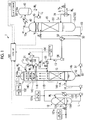
- Fig. 1 is a schematic view of a CO 2 recovery unit related to an embodiment of the invention.
- a CO 2 recovery unit 1 is an device that absorbs CO 2 in a flue gas (a gas to be treated) 11A containing CO 2 exhausted from industrial facilities, such as a boiler and a gas turbine, and recovers a high-concentration CO 2 gas.
- the CO 2 recovery unit 1 includes a quencher 12 that cools the flue gas 11A containing CO 2 exhausted from industrial facilities, such as a boiler and a gas turbine; a CO 2 absorber 14 that is provided in a subsequent stage of the quencher 12, brings the cooled flue gas 11A into contact with a CO 2 -absorbing solution 13, and makes the CO 2 -absorbing solution 13 absorb and remove CO 2 in the flue gas 11A; and a CO 2 -absorbing solution regenerator 15 that is provided in the subsequent stage of the CO 2 absorber 14, releases CO 2 from the CO 2 -absorbing solution 13 that has absorbed the CO 2 , and regenerates the CO 2 -absorbing solution 13.
- a quencher 12 that cools the flue gas 11A containing CO 2 exhausted from industrial facilities, such as a boiler and a gas turbine
- a CO 2 absorber 14 that is provided in a subsequent stage of the quencher 12, brings the cooled flue gas 11A into contact with a CO 2 -absorbing solution 13, and makes the CO 2 -absorbing solution
- the CO 2 -absorbing solution 13 circulates between the CO 2 absorber 14 and the CO 2 -absorbing solution regenerator 15.
- the CO 2 -absorbing solution 13 (lean solution) absorbs CO 2 in the CO 2 absorber 14, and is supplied to the CO 2 -absorbing solution regenerator 15 as the CO 2 -absorbing solution 13 (rich solution).
- the CO 2 -absorbing solution 13 (rich solution) has substantially all CO 2 removed and regenerated in the CO 2 -absorbing solution regenerator 15, and is supplied to the CO 2 absorber 14 as the CO 2 -absorbing solution 13 (lean solution).
- the quencher 12 has a quenching section 121 that cools the flue gas 11A.
- a circulation line L 1 is provided between a bottom part of the quencher 12 and a top part of the quenching section 121.
- a heat exchanger 122 that cools cooling water W 1 , and a circulation pump 123 that circulate the cooling water W 1 within the circulation line L 1 are provided in the circulation line L 1 .
- the flue gas 11A is cooled by bringing the flue gas 11A into countercurrent contact with the cooling water W 1 .
- the heat exchanger 122 cools the cooling water W 1 heated by the heat exchange with the flue gas 11A.
- the circulation pump 123 supplies the cooling water W 1 , which has flowed down to the bottom part of the quencher 12, to the top part of the quenching section 121 via the heat exchanger 122.
- the CO 2 absorber 14 includes a CO 2 absorption section 141 that is provided on a lower part side of the CO 2 absorber 14 and has the flue gas 11A cooled in the quencher 12 supplied thereto, a washing section 142 that is provided on an upper part side of the CO 2 absorber 14.
- a liquid storage section 144 that stores cleaning water W 2 for cleaning a flue gas 11B from which CO 2 has been removed is provided at a bottom part of the washing section 142.
- a circulation line L 2 through which the cleaning water W 2 , containing the CO 2 -absorbing solution 13 recovered in the liquid storage section 144, is supplied and circulated from a top part side of the washing section 142, is provided between the liquid storage section 144 and an upper part of the washing section 142.
- the circulation line L 2 is provided with a heat exchanger 21 that cools the cleaning water W 2 , and a circulation pump 22 that circulates the cleaning water W 2 , containing the CO 2 -absorbing solution 13 recovered in the liquid storage section 144, within the circulation line L 2 via the heat exchanger 21. Additionally, the circulation line L 2 is provided with an extraction line L 3 through which a portion of the cleaning water W 2 (cleaning water W 3 ) is extracted and supplied to the CO 2 absorption section 141. The extraction line L 3 is provided with a control valve 23 that adjusts the amount of supply of cleaning water W 3 to be supplied to the CO 2 -absorbing solution 13 (lean solution).
- the flue gas 11A containing CO 2 and the CO 2 -absorbing solution 13 containing alkanolamine or the like come into countercurrent contact with each other. Accordingly, CO 2 in the flue gas 11A is absorbed by the CO 2 -absorbing solution 13 through a chemical reaction shown in the following Formula. As a result, the flue gas 11A containing CO 2 becomes the flue gas 11B from which CO 2 has been removed by passing through the CO 2 absorption section 141.
- the flue gas 11B from which CO 2 has been removed rises via a chimney tray 145. Then, the flue gas 11B is brought into gas-liquid contact with the cleaning water W 2 supplied from the top part side of the washing section 142, and becomes a flue gas 11C from which the CO 2 -absorbing solution 13 entrained in the flue gas 11B has been recovered by circulation cleaning.
- the flue gas 11C is exhausted to the outside from a tower top part 14a of the CO 2 absorber 14 after mist in the gas is trapped by a mist eliminator 146.
- the rich solution supply tube 50 is provided with a rich solvent pump 51 that supplies the CO 2 -absorbing solution 13 (rich solution), which has absorbed CO 2 in the CO 2 absorber 14, toward the CO 2 -absorbing solution regenerator 15, and a rich-lean solution heat exchanger 52 that heats the CO 2 -absorbing solution 13 (rich solution) that has absorbed CO 2 , using the CO 2 -absorbing solution 13 (lean solution) which has been heated with saturated steam S and from which CO 2 has been removed.
- a rich solvent pump 51 that supplies the CO 2 -absorbing solution 13 (rich solution), which has absorbed CO 2 in the CO 2 absorber 14, toward the CO 2 -absorbing solution regenerator 15, and a rich-lean solution heat exchanger 52 that heats the CO 2 -absorbing solution 13 (rich solution) that has absorbed CO 2 , using the CO 2 -absorbing solution 13 (lean solution) which has been heated with saturated steam S and from which CO 2 has been removed.
- the CO 2 -absorbing solution regenerator 15 includes a CO 2 -absorbing solution supply part 151 that is provided at a central part of the CO 2 -absorbing solution regenerator 15 and has the CO 2 -absorbing solution 13, which has absorbed CO 2 , supplied thereto, and a mirror surface part 152 of a tower bottom part 15b of a lower part of the CO 2 -absorbing solution supply part 151.
- the tower bottom part 15b of the CO 2 -absorbing solution regenerator 15 is provided with a circulation line L 4 through which the CO 2 -absorbing solution 13 that has flowed down to the tower bottom part 15b circulates.
- the circulation line L 4 is provided with a regeneration heater 31 that heats the CO 2 -absorbing solution 13 with saturated steam S.
- a tower top part 15a of the CO 2 -absorbing solution regenerator 15 is provided with a gas exhaust line L 5 through which a CO 2 gas 41 accompanied by the saturated steam S is exhausted.
- the gas exhaust line L 5 is provided with a condenser 42 that condenses moisture in the CO 2 gas 41, and a separation drum 43 that separates the CO 2 gas 41 from condensed water W 5 .
- a CO 2 gas 44 from which the condensed water W 5 has been separated is released to the outside from an upper part of the separation drum 43.
- a condensed water line L 6 through which the condensed water W 5 separated by the separation drum 43 is supplied to the upper part of the CO 2 -absorbing solution regenerator 15 is provided between a bottom part of the separation drum 43 and the upper part of the CO 2 -absorbing solution regenerator 15.
- the condensed water line L 6 is provided with a condensed water circulation pump 45 that supplies the condensed water W 5 separated by the separation drum 43 to the upper part of the CO 2 -absorbing solution regenerator 15.
- the tower bottom part 15b of the CO 2 -absorbing solution regenerator 15 and an upper part of the CO 2 absorption section 141 of the CO 2 absorber 14 are provided with a lean solution supply tube 53 through which the CO 2 -absorbing solution 13 (lean solution) in the tower bottom part 15b of the CO 2 -absorbing solution regenerator 15 is supplied to the upper part of the CO 2 absorption section 141.
- the lean solution supply tube 53 is provided with the rich-lean solution heat exchanger 52 that heats the CO 2 -absorbing solution 13 (rich solution), which has absorbed CO 2 , using the CO 2 -absorbing solution 13 (lean solution) which has been heated with saturated steam and from which CO 2 has been removed, a lean solution pump 54 that supplies the lean solution in the tower bottom part 15b of the CO 2 -absorbing solution regenerator 15 to the upper part of the CO 2 absorption section 141, and a quenching section 55 that cools the CO 2 -absorbing solution 13 (lean solution) to a predetermined temperature.
- the CO 2 recovery unit 1 related to the present embodiment includes a flue gas detecting unit 101a that is provided in a flow passage for the flue gas 11A to be introduced into the quencher 12, a flue gas detecting unit 101b that is provided in a flow passage for the flue gas 11A exhausted from the quencher 12, a CO 2 concentration meter 102 that is provided in a flow passage for the flue gas 11C exhausted from CO 2 absorber 14, a CO 2 gas detecting unit 103 that is provided in a flow passage for the CO 2 gas 44 exhausted from the separation drum 43, and a concentration meter 104 that measures the concentration of the CO 2 -absorbing solution (lean solution) 13 to be supplied to the CO 2 absorber 14.
- a flue gas detecting unit 101a that is provided in a flow passage for the flue gas 11A to be introduced into the quencher 12
- a flue gas detecting unit 101b that is provided in a flow passage for the flue gas 11A exhausted from the quencher 12
- a flue gas detecting unit 101a measures CO 2 concentration in the flue gas 11A to be introduced into the quencher 12, and transmits the measured CO 2 concentration to a control unit 100.
- the flue gas detecting unit 101b measures the gas flow rate and the gas temperature of the flue gas 11A exhausted from the quencher 12, and transmits the measured CO 2 concentration, gas flow rate, and gas temperature to the control unit 100.
- the CO 2 concentration meter 102 detects CO 2 concentration in the flue gas 11C exhausted from the CO 2 absorber 14, and transmits the detected CO 2 concentration to the control unit 100.
- the CO 2 gas detecting unit 103 detects the gas flow rate and the concentration of the CO 2 gas 44 exhausted from the separation drum 43, and transmits the gas flow rate and the concentration to the control unit 100.
- the concentration meter 104 measures the concentration of the CO 2 -absorbing solution (lean solution) 13 to be supplied to the CO 2 absorber 14, and transmits the measured concentration of the CO 2 -absorbing solution (lean solution) 13 to the control unit 100.
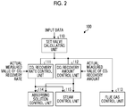
- Fig. 2 is a functional block diagram of the control unit 100 related to the present embodiment.
- the control unit 100 related to the present embodiment includes a set value calculating unit 110 that calculates set values as various reference values required for the operation of the CO 2 recovery unit 1 on the basis of input data, a CO 2 recovery rate control unit 111 and a CO 2 recovery amount control unit 112 that correct the set values on the basis of an actual measured value of the CO 2 recovery rate of the CO 2 recovery unit 1, and calculate corrected data, a flue gas control unit 113 that controls the flow rate of the flue gas 11A to be introduced into the quencher 12 via a control valve V 1 , an absorbing solution control unit 114 that controls the liquid amount of the CO 2 -absorbing solution (lean solution) 13 to be supplied to CO 2 absorber 14 via a control valve V 2 and controls the liquid amount of the CO 2 -absorbing solution (rich solution) 13 to be supplied to the CO 2 -absorbing solution regenerator 15 via a control valve V 3 , and a steam control unit 115 that controls the
- the set value calculating unit 110 calculates, according to a predetermined relational expression, a set value of the gas flow rate of the flue gas 11A based on a reference value that is set in advance on the basis of a CO 2 recovery rate target value and a CO 2 recovery amount target value, the CO 2 concentration and gas temperature in the flue gas 11A, and the concentration of the CO 2 -absorbing solution (lean solution) 13, a set value of the flow rate of the CO 2 -absorbing solution (lean solution) 13 to be supplied to CO 2 absorber 14, a set value of the flow rate of the CO 2 -absorbing solution (rich solution) 13 to be supplied to CO 2 -absorbing solution regenerator 15, and a set value of the flow rate of the saturated steam S to be supplied to the regeneration heater 31, and transmits the calculated results to the CO 2 recovery rate control unit 111, the CO 2 recovery amount control unit 112, and the flue gas control unit 113.
- the CO 2 recovery rate control unit 111 compares the CO 2 concentration in the flue gas 11A detected by the flue gas detecting unit 101 and the actual measured value of the CO 2 recovery rate measured by the CO 2 concentration meter 102 with the set values thereof, and calculates correction values (target values) obtained by calculating the flow rate of the saturated steam S and the flow rate of the CO 2 -absorbing solution 13 required in order to bring the CO 2 recovery rate close to the set values and by correcting the set values.
- the CO 2 recovery rate control unit 111 corrects a set value through proportional calculation and integration calculation for the deviation of a difference between the actual measured value and the target value of the CO 2 recovery rate.
- the CO 2 recovery rate control unit 111 transmits the corrected data to the absorbing solution control unit 114 and the steam control unit 115 as corrected data.
- the CO 2 recovery amount control unit 112 compares an actual measured value of the CO 2 recovery amount measured by the CO 2 gas detecting unit 103 with the target value of the CO 2 recovery amount, and calculates a correction value (target value) obtained by calculating the flow rate of the saturated steam S and the flow rate of the CO 2 -absorbing solution 13 required in order to make the CO 2 recovery amount reach the target value and by correcting a set value.
- the CO 2 recovery amount control unit 112 corrects the set value through proportional calculation and integration calculation for the deviation of a difference between the actual measured value and the target value of the CO 2 recovery amount.
- the CO 2 recovery amount control unit 112 transmits the corrected data to the absorbing solution control unit 114 and the steam control unit 115 as corrected data.
- the flue gas control unit 113 controls the flow rate of the flue gas 11A to be introduced into the quencher 12 via the control valve V 1 on the basis of the calculation results of the set value calculating unit 110.
- the absorbing solution control unit 114 controls the liquid amount of the CO 2 -absorbing solution (lean solution) 13 to be supplied to the CO 2 absorber 14 via the control valve V 2 on the basis of the calculation results of the CO 2 recovery rate control unit 111 and the CO 2 recovery amount control unit 112, and controls the liquid amount of the CO 2 -absorbing solution (rich solution) 13 to be supplied to the CO 2 -absorbing solution regenerator 15 via the control valve V 3 .
- the steam control unit 115 controls the flow rate of the saturated steam S to be supplied to the regeneration heater 31 via the control valve V 4 on the basis of the calculation results of the CO 2 recovery rate control unit 111 and the CO 2 recovery amount control unit 112.
- the cooled flue gas 11A is introduced into the CO 2 absorber 14 via a flue 16.
- the flue gas 11A introduced into the CO 2 absorber 14 is brought into countercurrent contact with the CO 2 -absorbing solution 13 containing alkanolamine or the like in the CO 2 absorption section 141, and becomes the flue gas 11B from which CO 2 in the flue gas 11A has been absorbed by the CO 2 -absorbing solution 13 and CO 2 has been removed.
- the flue gas 11B from which CO 2 has been removed rises via the chimney tray 145, is brought into gas-liquid contact with the cleaning water W 2 supplied from the top part side of the washing section 142, and becomes the flue gas 11C from which the CO 2 -absorbing solution 13 entrained in the flue gas 11B has been recovered by circulation cleaning.
- the CO 2 concentration in the flue gas 11C is measured by the CO 2 concentration meter 102 and the flue gas 11C is exhausted from the tower top part 14a of the CO 2 absorber 14 to the outside, after the mist in the gas is caught by the mist eliminator 146.
- the CO 2 -absorbing solution 13 (rich solution) that has absorbed CO 2 is sent to the rich-lean solution heat exchanger 52 by a rich solvent pump 51 via a rich solution supply tube 50 in the CO 2 absorber 14.
- the CO 2 -absorbing solution 13 (rich solution) sent from the CO 2 absorber 14 is heat-exchanged with the CO 2 -absorbing solution 13 (lean solution) sent from the CO 2 -absorbing solution regenerator 15.
- the CO 2 -absorbing solution 13 (rich solution) after this heat exchange is supplied to the upper part of the CO 2 -absorbing solution regenerator 15.
- the CO 2 -absorbing solution 13 supplied to the CO 2 -absorbing solution regenerator 15 has CO 2 removed therefrom and becomes a semi-lean solution, while flowing down to the tower bottom part 15b via the CO 2 -absorbing solution supply part 151.
- This semi-lean solution is circulated through the circulation line L 4 , is heated by the saturated steam S in the regeneration heater 31, and becomes the CO 2 -absorbing solution 13 (lean solution).
- the saturated steam S after being heated becomes the saturated steam condensed water W 4 .
- the CO 2 gas 41 removed from the CO 2 -absorbing solution 13 is released to the outside as the CO 2 gas 44 from which the condensed water W 5 has been separated through the upper part of the separation drum 43 after the moisture thereof is condensed by the condenser 42.
- the CO 2 concentration in the CO 2 gas 44 is measured.
- the CO 2 -absorbing solution 13 (lean solution) of the tower bottom part 15b of the CO 2 -absorbing solution regenerator 15 is supplied to the upper part of the CO 2 absorption section 141 of the CO 2 absorber 14 by the lean solution pump 54 after being heat-exchanged with the CO 2 -absorbing solution 13 (rich solution) by the rich-lean solution heat exchanger 52 via the lean solution supply tube 53.
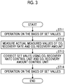
- Fig. 3 is a flow chart illustrating a method of controlling the CO 2 recovery rate control unit 111 and the CO 2 recovery amount control unit 112 related to the present embodiment.
- the CO 2 recovery rate control unit 111 controls the operation of the CO 2 recovery rate on the basis of the set value of the flow rate of the CO 2 -absorbing solution 13 based on a reference value that is set in advance on the basis of the CO 2 concentration in the flue gas 11A, the flow rate and temperature of the flue gas 11A, and a set value of the flow rate of the saturated steam S to be supplied to the regeneration heater 31, in early stages of the operation of the CO 2 recovery unit 1 (Step ST11).
- the CO 2 recovery rate control unit 111 measures an actual measured value of the CO 2 recovery rate using the flue gas detecting unit 101a and the CO 2 concentration meter 102, compares the actual measured value of the CO 2 recovery rate with the target value thereof (Step ST12), calculates the flow rate of the saturated steam S and the flow rate of the CO 2 -absorbing solution 13 in order to make the CO 2 recovery rate reach the target value, and corrects the set value (Step ST13).
- the CO 2 recovery rate control unit 111 controls the CO 2 recovery rate on the basis of the set value obtained by correcting the flow rate of the CO 2 -absorbing solution 13 and the flow rate of the saturated steam S to be supplied to the regeneration heater 31 (Step ST14).
- the CO 2 recovery rate control unit 111 corrects the set value such that the flow rate of the saturated steam S and the flow rate of the CO 2 -absorbing solution 13 (lean solution) are increased with respect to the set value, for example, in a case where the actual measured value (for example, 85%) of the CO 2 recovery rate is lower than the target value (for example, 90%). Accordingly, since the absorbing solution control unit 114 increases the flow rate of the CO 2 -absorbing solution 13 (lean solution) and the steam control unit 115 increases the flow rate of the saturated steam S, it is possible to increase the actual measured value of the CO 2 recovery rate of CO 2 recovery unit 1 toward the target value thereof.
- the CO 2 recovery amount control unit 112 controls the CO 2 recovery amount on the basis of the set value of the flow rate of the CO 2 -absorbing solution 13 based on the reference value that is set in advance on the basis of the CO 2 concentration in the flue gas 11A, the flow rate and temperature of the flue gas 11A, and a set value of the flow rate of the saturated steam S to be supplied to the regeneration heater 31, in early stages of the operation of the CO 2 recovery unit 1 (Step ST11).
- the CO 2 recovery amount control unit 112 measures the actual measured value of the CO 2 recovery amount using the CO 2 gas detecting unit 103, compares the measured actual measured value with the target value (Step ST12), calculates the flow rate of the saturated steam S and the flow rate of the CO 2 -absorbing solution 13 in order to make the CO 2 recovery amount reach the target value, and corrects the set value (Step ST13). Then, the CO 2 recovery amount control unit 112 controls the CO 2 recovery amount on the basis of the set value obtained by correcting the flow rate of the CO 2 -absorbing solution 13 and the flow rate of the saturated steam S to be supplied to the regeneration heater 31 (Step ST14).
- the CO 2 recovery amount control unit 112 corrects the set value such that the flow rate of the saturated steam S and the flow rate of the CO 2 -absorbing solution 13 (rich solution) are increased with respect to the set value, for example, in a case where the actual measured value (for example, 85 t/h) of the CO 2 recovery amount is lower than the target value (for example, 90 t/h). Accordingly, since the absorbing solution control unit 114 increases the flow rate of the CO 2 -absorbing solution 13 (rich solution) and the steam control unit 115 increases the flow rate of the saturated steam S, it is possible to increase the actual measured value of the CO 2 recovery amount of CO 2 recovery unit 1 toward the target value thereof.
- the circulation amount of the CO 2 -absorbing solution 13 and the amount of the saturated steam S supplied to the regeneration heater 31 can be appropriately controlled according to changes in the actual measured values of the CO 2 recovery rate and the CO 2 recovery amount in the flue gas 11A. Accordingly, even in a case where there is an influence on the predetermined relational expression to be used for the operation control of the CO 2 recovery unit and the precision of a measuring instrument due to changes in operation condition and the measuring instrument, the CO 2 recovery unit 1 that can control the CO 2 recovery amount and/or the CO 2 recovery rate to the target values with high accuracy can be realized.
- the CO 2 recovery unit 1 may have a configuration including any one of the CO 2 recovery rate control unit 111 and the CO 2 recovery amount control unit 112. Even in this case, the circulation amount of the CO 2 -absorbing solution 13 and the amount of the saturated steam S supplied to the regeneration heater 31 can be appropriately controlled according to changes in the actual measured values of the CO 2 recovery rate and the CO 2 recovery amount. Thus, it is possible to accurately control the CO 2 recovery rate and the CO 2 recovery amount.
- the CO 2 recovery unit 1 may control the flue gas control unit 113, the absorbing solution control unit 114, and the steam control unit 115, on the basis of the data obtained by further adding the CO 2 concentration in the flue gas 11A and the gas flow rate, temperature, and the like of the flue gas 11A to the corrected data that the CO 2 recovery rate control unit 111 and the CO 2 recovery amount control unit 112 have corrected.
- the CO 2 recovery unit 1 may operate any one of the CO 2 recovery rate control unit 111 and the CO 2 recovery amount control unit 112 in a first control mode where the corrected data is calculated and controlled at any time, and may operate the other in a second control mode where calculation processing is not performed at any time and the calculation processing is performed for each predetermined period.
- the interference between the corrected data can be reduced even in a case where a measurement error or the like has occurred between the calculation processing using the CO 2 recovery rate control unit 111, and the calculation processing using the CO 2 recovery amount control unit 112.
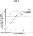
- FIG. 4 is a conceptual diagram of an operation control in which a dead band is provided.
- a horizontal axis represents operation time
- a vertical axis represents CO 2 recovery rate (%) or CO 2 recovery amount (t/h).
- the difference values D gradually decrease with elapse of the operation time t.
- the operation control is performed by proportional calculation by providing a dead band without performing the integration calculation regarding any one of the CO 2 recovery rate control unit 111 and the CO 2 recovery amount control unit 112.
Landscapes
- Chemical & Material Sciences (AREA)
- Engineering & Computer Science (AREA)
- Analytical Chemistry (AREA)
- General Chemical & Material Sciences (AREA)
- Oil, Petroleum & Natural Gas (AREA)
- Chemical Kinetics & Catalysis (AREA)
- Environmental & Geological Engineering (AREA)
- Health & Medical Sciences (AREA)
- Biomedical Technology (AREA)
- Mechanical Engineering (AREA)
- General Engineering & Computer Science (AREA)
- Treating Waste Gases (AREA)
- Gas Separation By Absorption (AREA)
- Carbon And Carbon Compounds (AREA)
Abstract
Description
- The present invention relates to a CO2 recovery unit and a CO2 recovery method, and particularly to a CO2 recovery unit and a CO2 recovery method that recover CO2 in a gas to be treated, using a CO2-absorbing solution.
- In the related art, CO2 recovery units that recover CO2 exhausted from boilers or the like of thermoelectric power plants are suggested (for example, refer to PTL 1). In the CO2 recovery units, flue gas is introduced into a CO2 absorber, a CO2-absorbing solution is brought into contact with CO2 included in the flue gas so that CO2 is made to be absorbed thereinto. The CO2-absorbing solution that has absorbed CO2 is sent to and heated and decarboxylated in a CO2-absorbing solution regenerator, and thereby, a high-concentration CO2 gas is recovered. The CO2-absorbing solution after the decarboxylation is supplied to the CO2 absorber by a liquid feed pump, and the CO2-absorbing solution is circulated and used between the CO2 absorber and the CO2-absorbing solution regenerator.
- [PTL 1] Japanese Patent No.
5237204 - Meanwhile, in the CO2 recovery unit described in PTL 1, the control of maintaining CO2 recovery amount at a target value on the basis of the fluctuations of the gas flow rate of the flue gas, the introduction temperature of the flue gas, and the like from reference values is performed. However, even in a case where the control is performed in this way, it may be difficult to maintain the CO2 recovery amount at the target value due to the influence of a predetermined relational expression used for the control and the precision of a measurement instrument.
- The invention has been made in view of such actual circumstances, and an object thereof is to provide a CO2 recovery unit and a CO2 recovery method with which a CO2 recovery amount and/or a CO2 recovery rate can be controlled with high accuracy toward target values. Solution to Problem
- A CO2 recovery unit of the invention includes a CO2 absorber that brings a gas to be treated and a CO2-absorbing solution into contact with each other to cause CO2 included in the gas to be treated to be absorbed into the CO2-absorbing solution; a CO2-absorbing solution regenerator that heats the CO2-absorbing solution which has absorbed CO2, releases CO2 from the CO2-absorbing solution, and regenerates the CO2-absorbing solution; a CO2 recovery rate control unit that, on the basis of an actual measured value and a target value of a recovery rate of CO2 in the gas to be treated, changes a circulation amount of the CO2-absorbing solution to be supplied to the CO2 absorber and changes a supply amount of saturated steam to be supplied to a regeneration heater of the CO2-absorbing solution regenerator to control a difference value between the actual measured value and the target value of the CO2 recovery rate to be within a predetermined range; and a CO2 recovery amount control unit that, on the basis of an actual measured value and a target value of a recovery amount of CO2 in the gas to be treated, changes the circulation amount of the CO2-absorbing solution to be supplied to the CO2 absorber and changes the supply amount of the saturated steam to be supplied to the regeneration heater of the CO2-absorbing solution regenerator to control a difference value between the actual measured value and the target value of the CO2 recovery amount to be within a predetermined range.
- According to this CO2 recovery unit, the circulation amount of the CO2-absorbing solution and the supply amount of the saturated steam to be supplied to the regeneration heater can be appropriately controlled according to changes in the actual measured values of the CO2 recovery rate and the CO2 recovery amount in the gas to be treated. Thus, even in a case where there is an influence on a predetermined relational expression to be used for control and the precision of a measuring instrument due to changes in operation condition and the measuring instrument, the CO2 recovery unit that can control the CO2 recovery amount and/or the CO2 recovery rate toward a target value with high accuracy can be realized.
- In the CO2 recovery unit of the invention, it is preferable that the CO2 recovery rate control unit controls the CO2 recovery rate through proportional calculation and integration calculation on the basis of the difference value between the actual measured value and the target value of the CO2 recovery rate.
- In the CO2 recovery unit of the invention, it is preferable that the CO2 recovery amount control unit controls the CO2 recovery amount through proportional calculation and integration calculation on the basis of the difference value between the actual measured value and the target value of the CO2 recovery amount.
- In the CO2 recovery unit of the invention, it is preferable that the CO2 recovery rate control unit includes a first control mode where the circulation amount and the supply amount of the saturated steam are calculated and controlled at any time, and a second control mode where the circulation amount and the supply amount of the saturated steam are calculated and controlled for each predetermined period, and the CO2 recovery amount control unit includes a first control mode where the circulation amount and the supply amount of the saturated steam are calculated and controlled at any time, and a second control mode where the circulation amount and the supply amount of the saturated steam are calculated and controlled for each predetermined period.
- In the CO2 recovery unit of the invention, it is preferable that any one of the CO2 recovery rate control unit and the CO2 recovery amount control unit is caused to be in the first control mode, and the other is caused to be in the second control mode.
- In the CO2 recovery unit of the invention, it is preferable that the CO2 recovery rate control unit is caused to be a first control mode where the circulation amount and the supply amount of the saturated steam are calculated and controlled at any time, the CO2 recovery amount control unit is caused to be a first control mode where the circulation amount and the supply amount of the saturated steam are calculated and controlled at any time, and control is performed by providing any one of the CO2 recovery amount control unit and the CO2 recovery rate control unit with a dead band.
- A CO2 recovery method of the invention includes a process of, in a CO2 absorber, bringing a gas to be treated and a CO2-absorbing solution into contact with each other to cause CO2 included in the gas to be treated to be absorbed into the CO2-absorbing solution; and a process of, in a CO2-absorbing solution regenerator, heating the CO2-absorbing solution which has absorbed CO2, releasing CO2 from the CO2-absorbing solution, and regenerating the CO2-absorbing solution. On the basis of an actual measured value and a target value of a recovery rate of CO2 in the gas to be treated, a circulation amount of the CO2-absorbing solution to be supplied to the CO2 absorber is changed and a supply amount of saturated steam to be supplied to a regeneration heater of the CO2-absorbing solution regenerator is changed to control a difference value between the actual measured value and the target value of the CO2 recovery rate to be within a predetermined range, and on the basis of an actual measured value and a target value of a recovery amount of CO2 in the gas to be treated, the circulation amount of the CO2-absorbing solution to be supplied to the CO2 absorber is changed and the supply amount of the saturated steam to be supplied to the regeneration heater of the CO2-absorbing solution regenerator is changed to control a difference value between the actual measured value and the target value of the CO2 recovery amount to be within a predetermined range.
- According to this CO2 recovery method, the circulation amount of the CO2-absorbing solution and the supply amount of the saturated steam to be supplied to the regeneration heater can be appropriately controlled according to changes in the actual measured values of the CO2 recovery rate and the CO2 recovery amount in the gas to be treated. Thus, even in a case where there is an influence on a predetermined relational expression to be used for control and the precision of a measuring instrument due to changes in operation condition and the measuring instrument, the CO2 recovery method that can control the CO2 recovery amount and/or the CO2 recovery rate toward the target values with high accuracy can be realized.
- In the CO2 recovery method of the invention, it is preferable that the CO2 recovery rate is controlled through proportional calculation and integration calculation on the basis of the difference value between the actual measured value and the target value of the CO2 recovery rate.
- In the CO2 recovery method of the invention, it is preferable that the CO2 recovery amount is controlled through proportional calculation and integration calculation on the basis of the difference value between the actual measured value and the target value of the CO2 recovery amount.
- In the CO2 recovery method of the invention, it is preferable that the CO2 recovery rate and the CO2 recovery amount are controlled by performing switching between a first control mode where the circulation amount and the supply amount of the saturated steam are calculated and controlled at any time, and a second control mode where the circulation amount and the supply amount of the saturated steam are calculated and controlled for each predetermined period.
- In the CO2 recovery method of the invention, it is preferable that any one of the CO2 recovery rate and the CO2 recovery amount is controlled in the first control mode, and the other is controlled in the second control mode.
- In the CO2 recovery method of the invention, it is preferable that the CO2 recovery rate and the CO2 recovery amount are controlled in the first control mode, and any one of the CO2 recovery amount and the CO2 recovery rate is controlled by providing a dead band.
- According to the invention, the CO2 recovery unit and the CO2 recovery method with which the CO2 recovery amount and/or the CO2 recovery rate can be controlled with high accuracy toward the target values can be realized.
-
-
Fig. 1 is a schematic view of a CO2 recovery unit related to an embodiment of the invention. -
Fig. 2 is a functional block diagram of a control unit related to the embodiment of the invention. -
Fig. 3 is a flow chart illustrating a method of controlling a CO2 recovery rate control unit and a CO2 recovery amount control unit related to the present embodiment. -
Fig. 4 is a conceptual diagram of an operation control in which a dead band of the CO2 recovery unit related to the present embodiment is provided. - The present inventors have noted that, in a related-art CO2 recovery unit, even in a case where a CO2 recovery amount and a CO2 recovery rate are controlled to target values obtained on the basis of relationships between CO2 concentration in a gas to be treated, the flow rate of the gas to be treated, and a reference value and a measured value of temperature, the target values and actual measured values may deviate from each other under the influence of measurement accuracy using a relational expression and a measurement instrument that are used for calculation. The present inventors also have found out that the CO2 recovery amount and/or the CO2 recovery rate can be controlled with high accuracy toward the target values by providing control units for the CO2 recovery amount and the CO2 recovery rate, respectively, to control the CO2 recovery amount and the CO2 recovery rate such that the CO2 recovery amount and the CO2 recovery rate that are actually measured using a gas flowmeter and a gas concentration meter reach the target values, and have completed the invention.
- Hereinafter, an embodiment of the invention will be described in detail with reference to the accompanying drawings. In addition, the invention is not limited to the following embodiment, and can be appropriately changed and carried out. Additionally, the configurations of CO2 recovery units related to the following respective embodiments can be appropriately combined and carried out.
-
Fig. 1 is a schematic view of a CO2 recovery unit related to an embodiment of the invention. As illustrated inFig. 1 , a CO2 recovery unit 1 is an device that absorbs CO2 in a flue gas (a gas to be treated) 11A containing CO2 exhausted from industrial facilities, such as a boiler and a gas turbine, and recovers a high-concentration CO2 gas. The CO2 recovery unit 1 includes aquencher 12 that cools theflue gas 11A containing CO2 exhausted from industrial facilities, such as a boiler and a gas turbine; a CO2 absorber 14 that is provided in a subsequent stage of thequencher 12, brings the cooledflue gas 11A into contact with a CO2-absorbing solution 13, and makes the CO2-absorbing solution 13 absorb and remove CO2 in theflue gas 11A; and a CO2-absorbing solution regenerator 15 that is provided in the subsequent stage of the CO2 absorber 14, releases CO2 from the CO2-absorbing solution 13 that has absorbed the CO2, and regenerates the CO2-absorbing solution 13. - In the CO2 recovery unit 1, the CO2-absorbing solution 13 circulates between the CO2 absorber 14 and the CO2-absorbing solution regenerator 15. The CO2-absorbing solution 13 (lean solution) absorbs CO2 in the CO2 absorber 14, and is supplied to the CO2-absorbing solution regenerator 15 as the CO2-absorbing solution 13 (rich solution). Additionally, the CO2-absorbing solution 13 (rich solution) has substantially all CO2 removed and regenerated in the CO2-absorbing solution regenerator 15, and is supplied to the CO2 absorber 14 as the CO2-absorbing solution 13 (lean solution).
- The
quencher 12 has aquenching section 121 that cools theflue gas 11A. A circulation line L1 is provided between a bottom part of thequencher 12 and a top part of thequenching section 121. Aheat exchanger 122 that cools cooling water W1, and acirculation pump 123 that circulate the cooling water W1 within the circulation line L1 are provided in the circulation line L1. - In the
quenching section 121, theflue gas 11A is cooled by bringing theflue gas 11A into countercurrent contact with the cooling water W1. Theheat exchanger 122 cools the cooling water W1 heated by the heat exchange with theflue gas 11A. Thecirculation pump 123 supplies the cooling water W1, which has flowed down to the bottom part of thequencher 12, to the top part of thequenching section 121 via theheat exchanger 122. - The CO2 absorber 14 includes a CO2 absorption section 141 that is provided on a lower part side of the CO2 absorber 14 and has the
flue gas 11A cooled in thequencher 12 supplied thereto, awashing section 142 that is provided on an upper part side of the CO2 absorber 14. Aliquid storage section 144 that stores cleaning water W2 for cleaning aflue gas 11B from which CO2 has been removed is provided at a bottom part of thewashing section 142. A circulation line L2, through which the cleaning water W2, containing the CO2-absorbing solution 13 recovered in theliquid storage section 144, is supplied and circulated from a top part side of thewashing section 142, is provided between theliquid storage section 144 and an upper part of thewashing section 142. The circulation line L2 is provided with aheat exchanger 21 that cools the cleaning water W2, and acirculation pump 22 that circulates the cleaning water W2, containing the CO2-absorbing solution 13 recovered in theliquid storage section 144, within the circulation line L2 via theheat exchanger 21. Additionally, the circulation line L2 is provided with an extraction line L3 through which a portion of the cleaning water W2 (cleaning water W3) is extracted and supplied to the CO2 absorption section 141. The extraction line L3 is provided with acontrol valve 23 that adjusts the amount of supply of cleaning water W3 to be supplied to the CO2-absorbing solution 13 (lean solution). - In the CO2 absorption section 141, the
flue gas 11A containing CO2 and the CO2-absorbing solution 13 containing alkanolamine or the like come into countercurrent contact with each other. Accordingly, CO2 in theflue gas 11A is absorbed by the CO2-absorbing solution 13 through a chemical reaction shown in the following Formula. As a result, theflue gas 11A containing CO2 becomes theflue gas 11B from which CO2 has been removed by passing through the CO2 absorption section 141.
R-NH2 + H2O + CO2 → R-NH3HCO3
- In the
washing section 142, theflue gas 11B from which CO2 has been removed rises via achimney tray 145. Then, theflue gas 11B is brought into gas-liquid contact with the cleaning water W2 supplied from the top part side of thewashing section 142, and becomes a flue gas 11C from which the CO2-absorbing solution 13 entrained in theflue gas 11B has been recovered by circulation cleaning. The flue gas 11C is exhausted to the outside from a towertop part 14a of the CO2 absorber 14 after mist in the gas is trapped by a mist eliminator 146. - A rich
solution supply tube 50 through which the CO2-absorbing solution 13 (rich solution), which has absorbed CO2 in the CO2 absorber 14, is supplied to an upper part side of the CO2-absorbing solution regenerator 15, is provided between a towerbottom part 14b of the CO2 absorber 14 and an upper part of the CO2-absorbing solution regenerator 15. The richsolution supply tube 50 is provided with a richsolvent pump 51 that supplies the CO2-absorbing solution 13 (rich solution), which has absorbed CO2 in the CO2 absorber 14, toward the CO2-absorbing solution regenerator 15, and a rich-leansolution heat exchanger 52 that heats the CO2-absorbing solution 13 (rich solution) that has absorbed CO2, using the CO2-absorbing solution 13 (lean solution) which has been heated with saturated steam S and from which CO2 has been removed. - The CO2-absorbing solution regenerator 15 includes a CO2-absorbing
solution supply part 151 that is provided at a central part of the CO2-absorbing solution regenerator 15 and has the CO2-absorbing solution 13, which has absorbed CO2, supplied thereto, and amirror surface part 152 of a towerbottom part 15b of a lower part of the CO2-absorbingsolution supply part 151. - The tower
bottom part 15b of the CO2-absorbing solution regenerator 15 is provided with a circulation line L4 through which the CO2-absorbing solution 13 that has flowed down to the towerbottom part 15b circulates. The circulation line L4 is provided with aregeneration heater 31 that heats the CO2-absorbing solution 13 with saturated steam S. - A tower
top part 15a of the CO2-absorbing solution regenerator 15 is provided with a gas exhaust line L5 through which a CO2 gas 41 accompanied by the saturated steam S is exhausted. The gas exhaust line L5 is provided with acondenser 42 that condenses moisture in the CO2 gas 41, and aseparation drum 43 that separates the CO2 gas 41 from condensed water W5. A CO2 gas 44 from which the condensed water W5 has been separated is released to the outside from an upper part of theseparation drum 43. A condensed water line L6 through which the condensed water W5 separated by theseparation drum 43 is supplied to the upper part of the CO2-absorbing solution regenerator 15 is provided between a bottom part of theseparation drum 43 and the upper part of the CO2-absorbing solution regenerator 15. The condensed water line L6 is provided with a condensedwater circulation pump 45 that supplies the condensed water W5 separated by theseparation drum 43 to the upper part of the CO2-absorbing solution regenerator 15. - Additionally, the tower
bottom part 15b of the CO2-absorbing solution regenerator 15 and an upper part of the CO2 absorption section 141 of the CO2 absorber 14 are provided with a leansolution supply tube 53 through which the CO2-absorbing solution 13 (lean solution) in the towerbottom part 15b of the CO2-absorbing solution regenerator 15 is supplied to the upper part of the CO2 absorption section 141. The leansolution supply tube 53 is provided with the rich-leansolution heat exchanger 52 that heats the CO2-absorbing solution 13 (rich solution), which has absorbed CO2, using the CO2-absorbing solution 13 (lean solution) which has been heated with saturated steam and from which CO2 has been removed, alean solution pump 54 that supplies the lean solution in the towerbottom part 15b of the CO2-absorbing solution regenerator 15 to the upper part of the CO2 absorption section 141, and aquenching section 55 that cools the CO2-absorbing solution 13 (lean solution) to a predetermined temperature. - The CO2 recovery unit 1 related to the present embodiment includes a flue
gas detecting unit 101a that is provided in a flow passage for theflue gas 11A to be introduced into thequencher 12, a fluegas detecting unit 101b that is provided in a flow passage for theflue gas 11A exhausted from thequencher 12, a CO2 concentration meter 102 that is provided in a flow passage for the flue gas 11C exhausted from CO2 absorber 14, a CO2gas detecting unit 103 that is provided in a flow passage for the CO2 gas 44 exhausted from theseparation drum 43, and aconcentration meter 104 that measures the concentration of the CO2-absorbing solution (lean solution) 13 to be supplied to the CO2 absorber 14. - A flue
gas detecting unit 101a measures CO2 concentration in theflue gas 11A to be introduced into thequencher 12, and transmits the measured CO2 concentration to acontrol unit 100. The fluegas detecting unit 101b measures the gas flow rate and the gas temperature of theflue gas 11A exhausted from thequencher 12, and transmits the measured CO2 concentration, gas flow rate, and gas temperature to thecontrol unit 100. The CO2 concentration meter 102 detects CO2 concentration in the flue gas 11C exhausted from the CO2 absorber 14, and transmits the detected CO2 concentration to thecontrol unit 100. - The CO2
gas detecting unit 103 detects the gas flow rate and the concentration of the CO2 gas 44 exhausted from theseparation drum 43, and transmits the gas flow rate and the concentration to thecontrol unit 100. Theconcentration meter 104 measures the concentration of the CO2-absorbing solution (lean solution) 13 to be supplied to the CO2 absorber 14, and transmits the measured concentration of the CO2-absorbing solution (lean solution) 13 to thecontrol unit 100. -
Fig. 2 is a functional block diagram of thecontrol unit 100 related to the present embodiment. Thecontrol unit 100 related to the present embodiment includes a setvalue calculating unit 110 that calculates set values as various reference values required for the operation of the CO2 recovery unit 1 on the basis of input data, a CO2 recoveryrate control unit 111 and a CO2 recoveryamount control unit 112 that correct the set values on the basis of an actual measured value of the CO2 recovery rate of the CO2 recovery unit 1, and calculate corrected data, a fluegas control unit 113 that controls the flow rate of theflue gas 11A to be introduced into thequencher 12 via a control valve V1, an absorbingsolution control unit 114 that controls the liquid amount of the CO2-absorbing solution (lean solution) 13 to be supplied to CO2 absorber 14 via a control valve V2 and controls the liquid amount of the CO2-absorbing solution (rich solution) 13 to be supplied to the CO2-absorbing solution regenerator 15 via a control valve V3, and asteam control unit 115 that controls the flow rate of the saturated steam S to be supplied to theregeneration heater 31 via a control valve V4. - The set
value calculating unit 110 calculates, according to a predetermined relational expression, a set value of the gas flow rate of theflue gas 11A based on a reference value that is set in advance on the basis of a CO2 recovery rate target value and a CO2 recovery amount target value, the CO2 concentration and gas temperature in theflue gas 11A, and the concentration of the CO2-absorbing solution (lean solution) 13, a set value of the flow rate of the CO2-absorbing solution (lean solution) 13 to be supplied to CO2 absorber 14, a set value of the flow rate of the CO2-absorbing solution (rich solution) 13 to be supplied to CO2-absorbing solution regenerator 15, and a set value of the flow rate of the saturated steam S to be supplied to theregeneration heater 31, and transmits the calculated results to the CO2 recoveryrate control unit 111, the CO2 recoveryamount control unit 112, and the fluegas control unit 113. - The CO2 recovery
rate control unit 111 compares the CO2 concentration in theflue gas 11A detected by the flue gas detecting unit 101 and the actual measured value of the CO2 recovery rate measured by the CO2 concentration meter 102 with the set values thereof, and calculates correction values (target values) obtained by calculating the flow rate of the saturated steam S and the flow rate of the CO2-absorbing solution 13 required in order to bring the CO2 recovery rate close to the set values and by correcting the set values. Here, the CO2 recoveryrate control unit 111 corrects a set value through proportional calculation and integration calculation for the deviation of a difference between the actual measured value and the target value of the CO2 recovery rate. The CO2 recoveryrate control unit 111 transmits the corrected data to the absorbingsolution control unit 114 and thesteam control unit 115 as corrected data. - The CO2 recovery
amount control unit 112 compares an actual measured value of the CO2 recovery amount measured by the CO2gas detecting unit 103 with the target value of the CO2 recovery amount, and calculates a correction value (target value) obtained by calculating the flow rate of the saturated steam S and the flow rate of the CO2-absorbing solution 13 required in order to make the CO2 recovery amount reach the target value and by correcting a set value. Here, the CO2 recoveryamount control unit 112 corrects the set value through proportional calculation and integration calculation for the deviation of a difference between the actual measured value and the target value of the CO2 recovery amount. The CO2 recoveryamount control unit 112 transmits the corrected data to the absorbingsolution control unit 114 and thesteam control unit 115 as corrected data. - The flue
gas control unit 113 controls the flow rate of theflue gas 11A to be introduced into thequencher 12 via the control valve V1 on the basis of the calculation results of the setvalue calculating unit 110. - The absorbing
solution control unit 114 controls the liquid amount of the CO2-absorbing solution (lean solution) 13 to be supplied to the CO2 absorber 14 via the control valve V2 on the basis of the calculation results of the CO2 recoveryrate control unit 111 and the CO2 recoveryamount control unit 112, and controls the liquid amount of the CO2-absorbing solution (rich solution) 13 to be supplied to the CO2-absorbing solution regenerator 15 via the control valve V3. - The
steam control unit 115 controls the flow rate of the saturated steam S to be supplied to theregeneration heater 31 via the control valve V4 on the basis of the calculation results of the CO2 recoveryrate control unit 111 and the CO2 recoveryamount control unit 112. - Next, the overall operation of the CO2 recovery unit 1 related to the present embodiment will be described. The
flue gas 11A containing CO2 exhausted from industrial facilities, such as a boiler and a gas turbine, is introduced into thequencher 12, and is brought into countercurrent contact with and cooled by the cooling water W1 after the CO2 concentration, gas flow rate, and temperature in theflue gas 11A are measured by the flue gas detecting unit 101. The cooledflue gas 11A is introduced into the CO2 absorber 14 via aflue 16. Theflue gas 11A introduced into the CO2 absorber 14 is brought into countercurrent contact with the CO2-absorbing solution 13 containing alkanolamine or the like in the CO2 absorption section 141, and becomes theflue gas 11B from which CO2 in theflue gas 11A has been absorbed by the CO2-absorbing solution 13 and CO2 has been removed. - The
flue gas 11B from which CO2 has been removed rises via thechimney tray 145, is brought into gas-liquid contact with the cleaning water W2 supplied from the top part side of thewashing section 142, and becomes the flue gas 11C from which the CO2-absorbing solution 13 entrained in theflue gas 11B has been recovered by circulation cleaning. The CO2 concentration in the flue gas 11C is measured by the CO2 concentration meter 102 and the flue gas 11C is exhausted from the towertop part 14a of the CO2 absorber 14 to the outside, after the mist in the gas is caught by the mist eliminator 146. - The CO2-absorbing solution 13 (rich solution) that has absorbed CO2 is sent to the rich-lean
solution heat exchanger 52 by a richsolvent pump 51 via a richsolution supply tube 50 in the CO2 absorber 14. In the rich-leansolution heat exchanger 52, the CO2-absorbing solution 13 (rich solution) sent from the CO2 absorber 14 is heat-exchanged with the CO2-absorbing solution 13 (lean solution) sent from the CO2-absorbing solution regenerator 15. The CO2-absorbing solution 13 (rich solution) after this heat exchange is supplied to the upper part of the CO2-absorbing solution regenerator 15. The CO2-absorbing solution 13 supplied to the CO2-absorbing solution regenerator 15 has CO2 removed therefrom and becomes a semi-lean solution, while flowing down to the towerbottom part 15b via the CO2-absorbingsolution supply part 151. This semi-lean solution is circulated through the circulation line L4, is heated by the saturated steam S in theregeneration heater 31, and becomes the CO2-absorbing solution 13 (lean solution). The saturated steam S after being heated becomes the saturated steam condensed water W4. The CO2 gas 41 removed from the CO2-absorbing solution 13 is released to the outside as the CO2 gas 44 from which the condensed water W5 has been separated through the upper part of theseparation drum 43 after the moisture thereof is condensed by thecondenser 42. In the CO2gas detecting unit 103, the CO2 concentration in the CO2 gas 44 is measured. - The CO2-absorbing solution 13 (lean solution) of the tower
bottom part 15b of the CO2-absorbing solution regenerator 15 is supplied to the upper part of the CO2 absorption section 141 of the CO2 absorber 14 by thelean solution pump 54 after being heat-exchanged with the CO2-absorbing solution 13 (rich solution) by the rich-leansolution heat exchanger 52 via the leansolution supply tube 53. -
Fig. 3 is a flow chart illustrating a method of controlling the CO2 recoveryrate control unit 111 and the CO2 recoveryamount control unit 112 related to the present embodiment. As illustrated inFig. 3 , the CO2 recoveryrate control unit 111 controls the operation of the CO2 recovery rate on the basis of the set value of the flow rate of the CO2-absorbing solution 13 based on a reference value that is set in advance on the basis of the CO2 concentration in theflue gas 11A, the flow rate and temperature of theflue gas 11A, and a set value of the flow rate of the saturated steam S to be supplied to theregeneration heater 31, in early stages of the operation of the CO2 recovery unit 1 (Step ST11). Additionally, after elapse of a predetermined period, the CO2 recoveryrate control unit 111 measures an actual measured value of the CO2 recovery rate using the fluegas detecting unit 101a and the CO2 concentration meter 102, compares the actual measured value of the CO2 recovery rate with the target value thereof (Step ST12), calculates the flow rate of the saturated steam S and the flow rate of the CO2-absorbing solution 13 in order to make the CO2 recovery rate reach the target value, and corrects the set value (Step ST13). The CO2 recoveryrate control unit 111 controls the CO2 recovery rate on the basis of the set value obtained by correcting the flow rate of the CO2-absorbing solution 13 and the flow rate of the saturated steam S to be supplied to the regeneration heater 31 (Step ST14). - Here, the CO2 recovery
rate control unit 111 corrects the set value such that the flow rate of the saturated steam S and the flow rate of the CO2-absorbing solution 13 (lean solution) are increased with respect to the set value, for example, in a case where the actual measured value (for example, 85%) of the CO2 recovery rate is lower than the target value (for example, 90%). Accordingly, since the absorbingsolution control unit 114 increases the flow rate of the CO2-absorbing solution 13 (lean solution) and thesteam control unit 115 increases the flow rate of the saturated steam S, it is possible to increase the actual measured value of the CO2 recovery rate of CO2 recovery unit 1 toward the target value thereof. - The CO2 recovery
amount control unit 112 controls the CO2 recovery amount on the basis of the set value of the flow rate of the CO2-absorbing solution 13 based on the reference value that is set in advance on the basis of the CO2 concentration in theflue gas 11A, the flow rate and temperature of theflue gas 11A, and a set value of the flow rate of the saturated steam S to be supplied to theregeneration heater 31, in early stages of the operation of the CO2 recovery unit 1 (Step ST11). Additionally, after elapse of a predetermined period, the CO2 recoveryamount control unit 112 measures the actual measured value of the CO2 recovery amount using the CO2gas detecting unit 103, compares the measured actual measured value with the target value (Step ST12), calculates the flow rate of the saturated steam S and the flow rate of the CO2-absorbing solution 13 in order to make the CO2 recovery amount reach the target value, and corrects the set value (Step ST13). Then, the CO2 recoveryamount control unit 112 controls the CO2 recovery amount on the basis of the set value obtained by correcting the flow rate of the CO2-absorbing solution 13 and the flow rate of the saturated steam S to be supplied to the regeneration heater 31 (Step ST14). - Here, the CO2 recovery
amount control unit 112 corrects the set value such that the flow rate of the saturated steam S and the flow rate of the CO2-absorbing solution 13 (rich solution) are increased with respect to the set value, for example, in a case where the actual measured value (for example, 85 t/h) of the CO2 recovery amount is lower than the target value (for example, 90 t/h). Accordingly, since the absorbingsolution control unit 114 increases the flow rate of the CO2-absorbing solution 13 (rich solution) and thesteam control unit 115 increases the flow rate of the saturated steam S, it is possible to increase the actual measured value of the CO2 recovery amount of CO2 recovery unit 1 toward the target value thereof. - As described above, according to the present embodiment, the circulation amount of the CO2-absorbing solution 13 and the amount of the saturated steam S supplied to the
regeneration heater 31 can be appropriately controlled according to changes in the actual measured values of the CO2 recovery rate and the CO2 recovery amount in theflue gas 11A. Accordingly, even in a case where there is an influence on the predetermined relational expression to be used for the operation control of the CO2 recovery unit and the precision of a measuring instrument due to changes in operation condition and the measuring instrument, the CO2 recovery unit 1 that can control the CO2 recovery amount and/or the CO2 recovery rate to the target values with high accuracy can be realized. - In addition, an example in which both of the CO2 recovery
rate control unit 111 and the CO2 recoveryamount control unit 112 are provided, and thus both of the CO2 recovery rate and the CO2 recovery amount are controlled has been described in the above-described embodiment. However, the invention is not limited to this configuration. The CO2 recovery unit 1 may have a configuration including any one of the CO2 recoveryrate control unit 111 and the CO2 recoveryamount control unit 112. Even in this case, the circulation amount of the CO2-absorbing solution 13 and the amount of the saturated steam S supplied to theregeneration heater 31 can be appropriately controlled according to changes in the actual measured values of the CO2 recovery rate and the CO2 recovery amount. Thus, it is possible to accurately control the CO2 recovery rate and the CO2 recovery amount. - Additionally, an example in which the absorbing
solution control unit 114 and thesteam control unit 115 are controlled on the basis of the corrected data that the CO2 recoveryrate control unit 111 and the CO2 recoveryamount control unit 112 have corrected has been described in the above-described embodiment. However, the invention is not limited to this configuration. The CO2 recovery unit 1 may control the fluegas control unit 113, the absorbingsolution control unit 114, and thesteam control unit 115, on the basis of the data obtained by further adding the CO2 concentration in theflue gas 11A and the gas flow rate, temperature, and the like of theflue gas 11A to the corrected data that the CO2 recoveryrate control unit 111 and the CO2 recoveryamount control unit 112 have corrected. - Moreover, an example in which the operation of the CO2 recovery unit 1 is controlled using the corrected data of both of the CO2 recovery
rate control unit 111 and the CO2 recoveryamount control unit 112 has been described in the above-described embodiment. However, the invention is not limited to this configuration. The CO2 recovery unit 1 may operate any one of the CO2 recoveryrate control unit 111 and the CO2 recoveryamount control unit 112 in a first control mode where the corrected data is calculated and controlled at any time, and may operate the other in a second control mode where calculation processing is not performed at any time and the calculation processing is performed for each predetermined period. By controlling the operation in this way, the interference between the corrected data can be reduced even in a case where a measurement error or the like has occurred between the calculation processing using the CO2 recoveryrate control unit 111, and the calculation processing using the CO2 recoveryamount control unit 112. Thus, it is possible to control the CO2 recovery rate and/or the CO2 recovery amount to the target values with high accuracy. - Moreover, in then above-described embodiment, an operation control may be performed by providing a dead band, without performing the integration calculation regarding any one of the CO2 recovery
rate control unit 111 and the CO2 recoveryamount control unit 112.Fig. 4 is a conceptual diagram of an operation control in which a dead band is provided. In addition, inFig. 4 , a horizontal axis represents operation time, and a vertical axis represents CO2 recovery rate (%) or CO2 recovery amount (t/h). - As illustrated in
Fig. 4 , in the present embodiment, for example if an operation control is performed such that difference values D between target values (SP) and actual measured values (PV) of the CO2 recovery rate and the CO2 recovery amount fall within a predetermined range by integration calculation based on the following Expression (1), the difference values D gradually decrease with elapse of the operation time t. Thus, when the difference values D between the target values (SP) and the actual measured values (PV) of the CO2 recovery rate (%) or CO2 recovery amount (t/h) have reached a range of operation time t2 smaller than a predetermined range B from the range of the operation time t1, the operation control is performed by proportional calculation by providing a dead band without performing the integration calculation regarding any one of the CO2 recoveryrate control unit 111 and the CO2 recoveryamount control unit 112. As a result, even in a case where an interference of the corrected data between the CO2 recoveryrate control unit 111 and the CO2 recoveryamount control unit 112 occurs, regarding any one of the CO2 recoveryrate control unit 111 and the CO2 recoveryamount control unit 112, a predetermined offset smaller than an offset (for example, about 2% of a set value of the CO2 recovery unit 1) caused by the interference of the corrected data between the target values (SP) and the actual measured values (PV) of the CO2 recovery rate (%) or the CO2 recovery amount (t/h) can be secured. Accordingly, since it is possible to prevent any interference of the corrected data, the offset caused by the interference of the corrected data at the time of the operation of CO2 recovery unit 1 can be reduced to a range of 0.5% to 1%.
[Expression 1]
- Additionally, an example in which the
flue gas 11A containing CO2 exhausted from industrial facilities, such as a boiler and a gas turbine, is treated by the CO2-absorbing solution 13 has been described in the above-described embodiment. However, as gases to be treated that are treated by the CO2-absorbing solution 13, various gases can be applied if they are gases containing CO2. -
- 1:
- CO2 RECOVERY UNIT
- 11A, 11B, 11C:
- FLUE GAS
- 12:
- QUENCHER
- 121:
- QUENCHING SECTION
- 122:
- HEAT EXCHANGER
- 123:
- CIRCULATION PUMP
- 13:
- CO2-ABSORBING SOLUTION
- 13S:
- STEAM
- 14:
- CO2 absorber
- 14a:
- TOWER TOP PART
- 14b:
- TOWER BOTTOM PART
- 141:
- CO2 ABSORPTION SECTION
- 142:
- WASHING SECTION
- 144:
- LIQUID STORAGE SECTION
- 145:
- CHIMNEY TRAY
- 146:
- MIST ELIMINATOR
- 15:
- CO2-ABSORBING SOLUTION REGENERATOR
- 15a:
- TOWER TOP PART
- 15b:
- TOWER BOTTOM PART
- 151:
- CO2-ABSORBING SOLUTION SUPPLY PART
- 152:
- MIRROR SURFACE PART
- 16:
- FLUE
- 21:
- HEAT EXCHANGER
- 22:
- CIRCULATION PUMP
- 23:
- CONTROL VALVE
- 31:
- REGENERATION HEATER
- 41, 44:
- CO2 GAS
- 42:
- CONDENSER
- 43:
- SEPARATION DRUM
- 45:
- CONDENSED WATER CIRCULATION PUMP
- 50:
- RICH SOLUTION SUPPLY TUBE
- 51:
- RICH SOLVENT PUMP
- 52:
- RICH-LEAN SOLUTION HEAT EXCHANGER
- 53:
- LEAN SOLUTION SUPPLY TUBE
- 54:
- LEAN SOLUTION PUMP
- 55:
- QUENCHING SECTION
- 101a:
- FLUE GAS DETECTING UNIT
- 101b:
- FLUE GAS DETECTING UNIT
- 102:
- CO2 CONCENTRATION METER
- 103:
- CO2 GAS DETECTING UNIT
- 104:
- CONCENTRATION METER
- 111:
- CO2 RECOVERY RATE CONTROL UNIT
- 112:
- CO2 RECOVERY AMOUNT CONTROL UNIT
- 113:
- FLUE GAS CONTROL UNIT
- 114:
- ABSORBING SOLUTION CONTROL UNIT
- 115:
- STEAM CONTROL UNIT
- L1, L2, L4:
- CIRCULATION LINE
- L3:
- EXTRACTION LINE
- L5:
- GAS EXHAUST LINE
- L6:
- CONDENSED WATER LINE
- S:
- SATURATED STEAM
- W1:
- COOLING WATER
- W2, W3:
- CLEANING WATER
- W4:
- SATURATED STEAM CONDENSED WATER
- W5:
- CONDENSED WATER
Claims (12)
- A CO2 recovery unit comprising:a CO2 absorber that brings a gas to be treated and a CO2-absorbing solution into contact with each other to cause CO2 included in the gas to be treated to be absorbed into the CO2-absorbing solution;a CO2-absorbing solution regenerator that heats the CO2-absorbing solution which has absorbed CO2, releases CO2 from the CO2-absorbing solution, and regenerates the CO2-absorbing solution;a CO2 recovery rate control unit that, on the basis of an actual measured value and a target value of a recovery rate of CO2 in the gas to be treated, changes a circulation amount of the CO2-absorbing solution to be supplied to the CO2 absorber and changes a supply amount of saturated steam to be supplied to a regeneration heater of the CO2-absorbing solution regenerator to control a difference value between the actual measured value and the target value of the CO2 recovery rate to be within a predetermined range; anda CO2 recovery amount control unit that, on the basis of an actual measured value and a target value of a recovery amount of CO2 in the gas to be treated, changes the circulation amount of the CO2-absorbing solution to be supplied to the CO2 absorber and changes the supply amount of the saturated steam to be supplied to the regeneration heater of the CO2-absorbing solution regenerator to control a difference value between the actual measured value and the target value of the CO2 recovery amount to be within a predetermined range.
- The CO2 recovery unit according to Claim 1,
wherein the CO2 recovery rate control unit controls the CO2 recovery rate through proportional calculation and integration calculation on the basis of the difference value between the actual measured value and the target value of the CO2 recovery rate. - The CO2 recovery unit according to Claim 1 or 2,
wherein the CO2 recovery amount control unit controls the CO2 recovery amount through proportional calculation and integration calculation on the basis of the difference value between the actual measured value and the target value of the CO2 recovery amount. - The CO2 recovery unit according to any one of Claims 1 to 3,
wherein the CO2 recovery rate control unit includes a first control mode where the circulation amount and the supply amount of the saturated steam are calculated and controlled at any time, and a second control mode where the circulation amount and the supply amount of the saturated steam are calculated and controlled for each predetermined period, and
wherein the CO2 recovery amount control unit includes a first control mode where the circulation amount and the supply amount of the saturated steam are calculated and controlled at any time, and a second control mode where the circulation amount and the supply amount of the saturated steam are calculated and controlled for each predetermined period. - The CO2 recovery unit according to Claim 4,
wherein any one of the CO2 recovery rate control unit and the CO2 recovery amount control unit is caused to be in the first control mode, and the other is caused to be in the second control mode. - The CO2 recovery unit according to any one of Claims 1 to 3,
wherein the CO2 recovery rate control unit is caused to be a first control mode where the circulation amount and the supply amount of the saturated steam are calculated and controlled at any time,
wherein the CO2 recovery amount control unit is caused to be a first control mode where the circulation amount and the supply amount of the saturated steam are calculated and controlled at any time, and
wherein control is performed by providing any one of the CO2 recovery amount control unit and the CO2 recovery rate control unit with a dead band. - A CO2 recovery method comprising:a process of, in a CO2 absorber, bringing a gas to be treated and a CO2-absorbing solution into contact with each other to cause CO2 included in the gas to be treated to be absorbed into the CO2-absorbing solution; anda process of, in a CO2-absorbing solution regenerator, heating the CO2-absorbing solution which has absorbed CO2, releasing CO2 from the CO2-absorbing solution, and regenerating the CO2-absorbing solution,wherein, on the basis of an actual measured value and a target value of a recovery rate of CO2 in the gas to be treated, a circulation amount of the CO2-absorbing solution to be supplied to the CO2 absorber is changed and a supply amount of saturated steam to be supplied to a regeneration heater of the CO2-absorbing solution regenerator is changed to control a difference value between the actual measured value and the target value of the CO2 recovery rate to be within a predetermined range, andwherein, on the basis of an actual measured value and a target value of a recovery amount of CO2 in the gas to be treated, the circulation amount of the CO2-absorbing solution to be supplied to the CO2 absorber is changed and the supply amount of the saturated steam to be supplied to the regeneration heater of the CO2-absorbing solution regenerator is changed to control a difference value between the actual measured value and the target value of the CO2 recovery amount to be within a predetermined range.
- The CO2 recovery method according to Claim 7,
wherein the CO2 recovery rate is controlled through proportional calculation and integration calculation on the basis of the difference value between the actual measured value and the target value of the CO2 recovery rate. - The CO2 recovery method according to Claim 7 or 8,
wherein the CO2 recovery amount is controlled through proportional calculation and integration calculation on the basis of the difference value between the actual measured value and the target value of the CO2 recovery amount. - The CO2 recovery method according to any one of Claims 7 to 9,
wherein the CO2 recovery rate and the CO2 recovery amount are controlled by performing switching between a first control mode where the circulation amount and the supply amount of the saturated steam are calculated and controlled at any time, and a second control mode where the circulation amount and the supply amount of the saturated steam are calculated and controlled for each predetermined period. - The CO2 recovery method according to Claim 10,
wherein any one of the CO2 recovery rate and the CO2 recovery amount is controlled in the first control mode, and the other is controlled in the second control mode. - The CO2 recovery method according to Claim 10,
wherein the CO2 recovery rate and the CO2 recovery amount are controlled in the first control mode, and any one of the CO2 recovery amount and the CO2 recovery rate is controlled by providing a dead band.
Applications Claiming Priority (2)
| Application Number | Priority Date | Filing Date | Title |
|---|---|---|---|
| JP2014142554A JP6325376B2 (en) | 2014-07-10 | 2014-07-10 | CO2 recovery device and CO2 recovery method |
| PCT/JP2015/067752 WO2016006416A1 (en) | 2014-07-10 | 2015-06-19 | Co2 recovery device and co2 recovery method |
Publications (3)
| Publication Number | Publication Date |
|---|---|
| EP3187242A1 true EP3187242A1 (en) | 2017-07-05 |
| EP3187242A4 EP3187242A4 (en) | 2017-07-05 |
| EP3187242B1 EP3187242B1 (en) | 2018-11-21 |
Family
ID=55064055
Family Applications (1)
| Application Number | Title | Priority Date | Filing Date |
|---|---|---|---|
| EP15819384.7A Active EP3187242B1 (en) | 2014-07-10 | 2015-06-19 | Co2 recovery unit and co2 recovery method |
Country Status (6)
| Country | Link |
|---|---|
| US (2) | US10213726B2 (en) |
| EP (1) | EP3187242B1 (en) |
| JP (1) | JP6325376B2 (en) |
| AU (1) | AU2015286249B2 (en) |
| CA (1) | CA2954234C (en) |
| WO (1) | WO2016006416A1 (en) |
Cited By (1)
| Publication number | Priority date | Publication date | Assignee | Title |
|---|---|---|---|---|
| CN112473322A (en) * | 2019-09-12 | 2021-03-12 | 株式会社东芝 | Carbon dioxide recovery system and method for operating same |
Families Citing this family (4)
| Publication number | Priority date | Publication date | Assignee | Title |
|---|---|---|---|---|
| JP6659351B2 (en) * | 2015-12-21 | 2020-03-04 | 株式会社東芝 | Carbon dioxide separation and recovery system and operation control method thereof |
| US12209225B2 (en) * | 2019-06-19 | 2025-01-28 | Jgc Corporation | Natural gas pretreatment system and method for pretreating natural gas |
| JP7510479B2 (en) * | 2022-11-21 | 2024-07-03 | 株式会社大気社 | Collection System |
| JP7834707B2 (en) * | 2023-12-04 | 2026-03-24 | スチールプランテック株式会社 | Carbon dioxide capture system and method, and electric furnace exhaust gas treatment equipment and method |
Family Cites Families (8)
| Publication number | Priority date | Publication date | Assignee | Title |
|---|---|---|---|---|
| CA2689453C (en) * | 2009-06-17 | 2012-08-28 | Mitsubishi Heavy Industries, Ltd. | Co2 recovering apparatus and method |
| JP5237204B2 (en) | 2009-06-17 | 2013-07-17 | 三菱重工業株式会社 | CO2 recovery apparatus and method |
| JP5349221B2 (en) * | 2009-09-08 | 2013-11-20 | 株式会社東芝 | Carbon dioxide recovery device |
| JP5527095B2 (en) * | 2010-08-09 | 2014-06-18 | 株式会社Ihi | Carbon dioxide recovery method and recovery apparatus |
| JP5694137B2 (en) * | 2011-01-05 | 2015-04-01 | 株式会社東芝 | Carbon dioxide separation and recovery system and control method thereof |
| JP5693295B2 (en) * | 2011-02-28 | 2015-04-01 | 三菱重工業株式会社 | CO2 recovery device and operation control method of CO2 recovery device |
| JP6216490B2 (en) * | 2012-02-03 | 2017-10-18 | 三菱重工業株式会社 | CO2 recovery device |
| JP5767609B2 (en) | 2012-06-25 | 2015-08-19 | 株式会社東芝 | Carbon dioxide recovery device and operation method thereof |
-
2014
- 2014-07-10 JP JP2014142554A patent/JP6325376B2/en active Active
-
2015
- 2015-06-19 WO PCT/JP2015/067752 patent/WO2016006416A1/en not_active Ceased
- 2015-06-19 AU AU2015286249A patent/AU2015286249B2/en active Active
- 2015-06-19 EP EP15819384.7A patent/EP3187242B1/en active Active
- 2015-06-19 CA CA2954234A patent/CA2954234C/en active Active
-
2017
- 2017-01-03 US US15/397,433 patent/US10213726B2/en active Active
-
2019
- 2019-01-09 US US16/243,459 patent/US10525403B2/en active Active
Cited By (2)
| Publication number | Priority date | Publication date | Assignee | Title |
|---|---|---|---|---|
| CN112473322A (en) * | 2019-09-12 | 2021-03-12 | 株式会社东芝 | Carbon dioxide recovery system and method for operating same |
| CN112473322B (en) * | 2019-09-12 | 2023-03-03 | 株式会社东芝 | Carbon dioxide recovery system and method for operating same |
Also Published As
| Publication number | Publication date |
|---|---|
| EP3187242B1 (en) | 2018-11-21 |
| US10525403B2 (en) | 2020-01-07 |
| CA2954234C (en) | 2018-10-23 |
| CA2954234A1 (en) | 2016-01-14 |
| AU2015286249B2 (en) | 2018-03-08 |
| US20170113178A1 (en) | 2017-04-27 |
| WO2016006416A1 (en) | 2016-01-14 |
| AU2015286249A1 (en) | 2017-01-12 |
| EP3187242A4 (en) | 2017-07-05 |
| JP2016016392A (en) | 2016-02-01 |
| US10213726B2 (en) | 2019-02-26 |
| JP6325376B2 (en) | 2018-05-16 |
| US20190143259A1 (en) | 2019-05-16 |
Similar Documents
| Publication | Publication Date | Title |
|---|---|---|
| AU2015286248B2 (en) | CO2 recovery unit and CO2 recovery method | |
| US10525403B2 (en) | CO2 recovery unit and CO2 recovery method | |
| US10427093B2 (en) | CO2 recovery apparatus and CO2 recovery process | |
| JP5039651B2 (en) | Carbon dioxide recovery system in exhaust gas | |
| EP3020463B1 (en) | Carbon dioxide capture apparatus and method of capturing carbon dioxide | |
| JP5383339B2 (en) | Concentration management method for CO2 absorbent used in CO2 recovery equipment | |
| US10449481B2 (en) | CO2 recovery unit and CO2 recovery method | |
| JP5527095B2 (en) | Carbon dioxide recovery method and recovery apparatus | |
| US10677704B2 (en) | System for analyzing carbon dioxide concentration of amine-based absorbing solution, carbon dioxide recovery system, and method of operating the same | |
| EP3108954B1 (en) | Co2 recovery device and co2 recovery method | |
| JP2010100491A (en) | Device and method for carbon dioxide recovery |
Legal Events
| Date | Code | Title | Description |
|---|---|---|---|
| STAA | Information on the status of an ep patent application or granted ep patent |
Free format text: STATUS: THE INTERNATIONAL PUBLICATION HAS BEEN MADE |
|
| PUAI | Public reference made under article 153(3) epc to a published international application that has entered the european phase |
Free format text: ORIGINAL CODE: 0009012 |
|
| STAA | Information on the status of an ep patent application or granted ep patent |
Free format text: STATUS: REQUEST FOR EXAMINATION WAS MADE |
|
| 17P | Request for examination filed |
Effective date: 20161230 |
|
| A4 | Supplementary search report drawn up and despatched |
Effective date: 20170511 |
|
| AK | Designated contracting states |
Kind code of ref document: A1 Designated state(s): AL AT BE BG CH CY CZ DE DK EE ES FI FR GB GR HR HU IE IS IT LI LT LU LV MC MK MT NL NO PL PT RO RS SE SI SK SM TR |
|
| AX | Request for extension of the european patent |
Extension state: BA ME |
|
| DAV | Request for validation of the european patent (deleted) | ||
| DAX | Request for extension of the european patent (deleted) | ||
| GRAP | Despatch of communication of intention to grant a patent |
Free format text: ORIGINAL CODE: EPIDOSNIGR1 |
|
| STAA | Information on the status of an ep patent application or granted ep patent |
Free format text: STATUS: GRANT OF PATENT IS INTENDED |
|
| INTG | Intention to grant announced |
Effective date: 20180201 |
|
| GRAS | Grant fee paid |
Free format text: ORIGINAL CODE: EPIDOSNIGR3 |
|
| GRAJ | Information related to disapproval of communication of intention to grant by the applicant or resumption of examination proceedings by the epo deleted |
Free format text: ORIGINAL CODE: EPIDOSDIGR1 |
|
| GRAL | Information related to payment of fee for publishing/printing deleted |
Free format text: ORIGINAL CODE: EPIDOSDIGR3 |
|
| STAA | Information on the status of an ep patent application or granted ep patent |
Free format text: STATUS: REQUEST FOR EXAMINATION WAS MADE |
|
| GRAP | Despatch of communication of intention to grant a patent |
Free format text: ORIGINAL CODE: EPIDOSNIGR1 |
|
| STAA | Information on the status of an ep patent application or granted ep patent |
Free format text: STATUS: GRANT OF PATENT IS INTENDED |
|
| INTC | Intention to grant announced (deleted) | ||
| RIN1 | Information on inventor provided before grant (corrected) |
Inventor name: NAKAGAWA, YOSUKE Inventor name: TSUJIUCHI, TATSUYA Inventor name: SHIMADA, DAISUKE |
|
| INTG | Intention to grant announced |
Effective date: 20180710 |
|
| RAP1 | Party data changed (applicant data changed or rights of an application transferred) |
Owner name: MITSUBISHI HEAVY INDUSTRIES ENGINEERING, LTD. |
|
| GRAA | (expected) grant |
Free format text: ORIGINAL CODE: 0009210 |
|
| STAA | Information on the status of an ep patent application or granted ep patent |
Free format text: STATUS: THE PATENT HAS BEEN GRANTED |
|
| AK | Designated contracting states |
Kind code of ref document: B1 Designated state(s): AL AT BE BG CH CY CZ DE DK EE ES FI FR GB GR HR HU IE IS IT LI LT LU LV MC MK MT NL NO PL PT RO RS SE SI SK SM TR |
|
| REG | Reference to a national code |
Ref country code: CH Ref legal event code: EP |
|
| REG | Reference to a national code |
Ref country code: IE Ref legal event code: FG4D |
|
| REG | Reference to a national code |
Ref country code: DE Ref legal event code: R096 Ref document number: 602015020184 Country of ref document: DE |
|
| REG | Reference to a national code |
Ref country code: AT Ref legal event code: REF Ref document number: 1066908 Country of ref document: AT Kind code of ref document: T Effective date: 20181215 |
|
| REG | Reference to a national code |
Ref country code: NL Ref legal event code: FP |
|
| REG | Reference to a national code |
Ref country code: NO Ref legal event code: T2 Effective date: 20181121 |
|
| REG | Reference to a national code |
Ref country code: AT Ref legal event code: MK05 Ref document number: 1066908 Country of ref document: AT Kind code of ref document: T Effective date: 20181121 |
|
| PG25 | Lapsed in a contracting state [announced via postgrant information from national office to epo] |
Ref country code: IS Free format text: LAPSE BECAUSE OF FAILURE TO SUBMIT A TRANSLATION OF THE DESCRIPTION OR TO PAY THE FEE WITHIN THE PRESCRIBED TIME-LIMIT Effective date: 20190321 Ref country code: FI Free format text: LAPSE BECAUSE OF FAILURE TO SUBMIT A TRANSLATION OF THE DESCRIPTION OR TO PAY THE FEE WITHIN THE PRESCRIBED TIME-LIMIT Effective date: 20181121 Ref country code: LV Free format text: LAPSE BECAUSE OF FAILURE TO SUBMIT A TRANSLATION OF THE DESCRIPTION OR TO PAY THE FEE WITHIN THE PRESCRIBED TIME-LIMIT Effective date: 20181121 Ref country code: AT Free format text: LAPSE BECAUSE OF FAILURE TO SUBMIT A TRANSLATION OF THE DESCRIPTION OR TO PAY THE FEE WITHIN THE PRESCRIBED TIME-LIMIT Effective date: 20181121 Ref country code: HR Free format text: LAPSE BECAUSE OF FAILURE TO SUBMIT A TRANSLATION OF THE DESCRIPTION OR TO PAY THE FEE WITHIN THE PRESCRIBED TIME-LIMIT Effective date: 20181121 Ref country code: LT Free format text: LAPSE BECAUSE OF FAILURE TO SUBMIT A TRANSLATION OF THE DESCRIPTION OR TO PAY THE FEE WITHIN THE PRESCRIBED TIME-LIMIT Effective date: 20181121 Ref country code: BG Free format text: LAPSE BECAUSE OF FAILURE TO SUBMIT A TRANSLATION OF THE DESCRIPTION OR TO PAY THE FEE WITHIN THE PRESCRIBED TIME-LIMIT Effective date: 20190221 Ref country code: ES Free format text: LAPSE BECAUSE OF FAILURE TO SUBMIT A TRANSLATION OF THE DESCRIPTION OR TO PAY THE FEE WITHIN THE PRESCRIBED TIME-LIMIT Effective date: 20181121 |
|
| PG25 | Lapsed in a contracting state [announced via postgrant information from national office to epo] |
Ref country code: PT Free format text: LAPSE BECAUSE OF FAILURE TO SUBMIT A TRANSLATION OF THE DESCRIPTION OR TO PAY THE FEE WITHIN THE PRESCRIBED TIME-LIMIT Effective date: 20190321 Ref country code: RS Free format text: LAPSE BECAUSE OF FAILURE TO SUBMIT A TRANSLATION OF THE DESCRIPTION OR TO PAY THE FEE WITHIN THE PRESCRIBED TIME-LIMIT Effective date: 20181121 Ref country code: GR Free format text: LAPSE BECAUSE OF FAILURE TO SUBMIT A TRANSLATION OF THE DESCRIPTION OR TO PAY THE FEE WITHIN THE PRESCRIBED TIME-LIMIT Effective date: 20190222 Ref country code: SE Free format text: LAPSE BECAUSE OF FAILURE TO SUBMIT A TRANSLATION OF THE DESCRIPTION OR TO PAY THE FEE WITHIN THE PRESCRIBED TIME-LIMIT Effective date: 20181121 Ref country code: AL Free format text: LAPSE BECAUSE OF FAILURE TO SUBMIT A TRANSLATION OF THE DESCRIPTION OR TO PAY THE FEE WITHIN THE PRESCRIBED TIME-LIMIT Effective date: 20181121 |
|
| PG25 | Lapsed in a contracting state [announced via postgrant information from national office to epo] |
Ref country code: PL Free format text: LAPSE BECAUSE OF FAILURE TO SUBMIT A TRANSLATION OF THE DESCRIPTION OR TO PAY THE FEE WITHIN THE PRESCRIBED TIME-LIMIT Effective date: 20181121 Ref country code: CZ Free format text: LAPSE BECAUSE OF FAILURE TO SUBMIT A TRANSLATION OF THE DESCRIPTION OR TO PAY THE FEE WITHIN THE PRESCRIBED TIME-LIMIT Effective date: 20181121 Ref country code: DK Free format text: LAPSE BECAUSE OF FAILURE TO SUBMIT A TRANSLATION OF THE DESCRIPTION OR TO PAY THE FEE WITHIN THE PRESCRIBED TIME-LIMIT Effective date: 20181121 |
|
| REG | Reference to a national code |
Ref country code: DE Ref legal event code: R097 Ref document number: 602015020184 Country of ref document: DE |
|
| PG25 | Lapsed in a contracting state [announced via postgrant information from national office to epo] |
Ref country code: EE Free format text: LAPSE BECAUSE OF FAILURE TO SUBMIT A TRANSLATION OF THE DESCRIPTION OR TO PAY THE FEE WITHIN THE PRESCRIBED TIME-LIMIT Effective date: 20181121 Ref country code: SM Free format text: LAPSE BECAUSE OF FAILURE TO SUBMIT A TRANSLATION OF THE DESCRIPTION OR TO PAY THE FEE WITHIN THE PRESCRIBED TIME-LIMIT Effective date: 20181121 Ref country code: RO Free format text: LAPSE BECAUSE OF FAILURE TO SUBMIT A TRANSLATION OF THE DESCRIPTION OR TO PAY THE FEE WITHIN THE PRESCRIBED TIME-LIMIT Effective date: 20181121 Ref country code: SK Free format text: LAPSE BECAUSE OF FAILURE TO SUBMIT A TRANSLATION OF THE DESCRIPTION OR TO PAY THE FEE WITHIN THE PRESCRIBED TIME-LIMIT Effective date: 20181121 |
|
| PLBE | No opposition filed within time limit |
Free format text: ORIGINAL CODE: 0009261 |
|
| STAA | Information on the status of an ep patent application or granted ep patent |
Free format text: STATUS: NO OPPOSITION FILED WITHIN TIME LIMIT |
|
| 26N | No opposition filed |
Effective date: 20190822 |
|
| PG25 | Lapsed in a contracting state [announced via postgrant information from national office to epo] |
Ref country code: SI Free format text: LAPSE BECAUSE OF FAILURE TO SUBMIT A TRANSLATION OF THE DESCRIPTION OR TO PAY THE FEE WITHIN THE PRESCRIBED TIME-LIMIT Effective date: 20181121 |
|
| PG25 | Lapsed in a contracting state [announced via postgrant information from national office to epo] |
Ref country code: MC Free format text: LAPSE BECAUSE OF FAILURE TO SUBMIT A TRANSLATION OF THE DESCRIPTION OR TO PAY THE FEE WITHIN THE PRESCRIBED TIME-LIMIT Effective date: 20181121 |
|
| REG | Reference to a national code |
Ref country code: CH Ref legal event code: PL |
|
| REG | Reference to a national code |
Ref country code: BE Ref legal event code: MM Effective date: 20190630 |
|
| PG25 | Lapsed in a contracting state [announced via postgrant information from national office to epo] |
Ref country code: TR Free format text: LAPSE BECAUSE OF FAILURE TO SUBMIT A TRANSLATION OF THE DESCRIPTION OR TO PAY THE FEE WITHIN THE PRESCRIBED TIME-LIMIT Effective date: 20181121 |
|
| PG25 | Lapsed in a contracting state [announced via postgrant information from national office to epo] |
Ref country code: IE Free format text: LAPSE BECAUSE OF NON-PAYMENT OF DUE FEES Effective date: 20190619 |
|
| PG25 | Lapsed in a contracting state [announced via postgrant information from national office to epo] |
Ref country code: LI Free format text: LAPSE BECAUSE OF NON-PAYMENT OF DUE FEES Effective date: 20190630 Ref country code: CH Free format text: LAPSE BECAUSE OF NON-PAYMENT OF DUE FEES Effective date: 20190630 Ref country code: LU Free format text: LAPSE BECAUSE OF NON-PAYMENT OF DUE FEES Effective date: 20190619 Ref country code: BE Free format text: LAPSE BECAUSE OF NON-PAYMENT OF DUE FEES Effective date: 20190630 |
|
| PG25 | Lapsed in a contracting state [announced via postgrant information from national office to epo] |
Ref country code: FR Free format text: LAPSE BECAUSE OF NON-PAYMENT OF DUE FEES Effective date: 20190630 |
|
| PG25 | Lapsed in a contracting state [announced via postgrant information from national office to epo] |
Ref country code: CY Free format text: LAPSE BECAUSE OF FAILURE TO SUBMIT A TRANSLATION OF THE DESCRIPTION OR TO PAY THE FEE WITHIN THE PRESCRIBED TIME-LIMIT Effective date: 20181121 |
|
| PG25 | Lapsed in a contracting state [announced via postgrant information from national office to epo] |
Ref country code: HU Free format text: LAPSE BECAUSE OF FAILURE TO SUBMIT A TRANSLATION OF THE DESCRIPTION OR TO PAY THE FEE WITHIN THE PRESCRIBED TIME-LIMIT; INVALID AB INITIO Effective date: 20150619 Ref country code: MT Free format text: LAPSE BECAUSE OF FAILURE TO SUBMIT A TRANSLATION OF THE DESCRIPTION OR TO PAY THE FEE WITHIN THE PRESCRIBED TIME-LIMIT Effective date: 20181121 |
|
| PG25 | Lapsed in a contracting state [announced via postgrant information from national office to epo] |
Ref country code: MK Free format text: LAPSE BECAUSE OF FAILURE TO SUBMIT A TRANSLATION OF THE DESCRIPTION OR TO PAY THE FEE WITHIN THE PRESCRIBED TIME-LIMIT Effective date: 20181121 |
|
| P01 | Opt-out of the competence of the unified patent court (upc) registered |
Effective date: 20230522 |
|
| REG | Reference to a national code |
Ref country code: DE Ref legal event code: R081 Ref document number: 602015020184 Country of ref document: DE Owner name: MITSUBISHI HEAVY INDUSTRIES, LTD., JP Free format text: FORMER OWNER: MITSUBISHI HEAVY INDUSTRIES ENGINEERING, LTD., YOKOHAMA-SHI, KANAGAWA, JP |
|
| REG | Reference to a national code |
Ref country code: DE Ref legal event code: R081 Ref document number: 602015020184 Country of ref document: DE Owner name: MITSUBISHI HEAVY INDUSTRIES, LTD., JP Free format text: FORMER OWNER: MHI ENGINEERING, LTD., YOKOHAMA-SHI, KANAGAWA, JP |
|
| REG | Reference to a national code |
Ref country code: NL Ref legal event code: PD Owner name: MITSUBISHI HEAVY INDUSTRIES, LTD.; JP Free format text: DETAILS ASSIGNMENT: CHANGE OF OWNER(S), ASSIGNMENT; FORMER OWNER NAME: MHI ENGINEERING, LTD. Effective date: 20231206 Ref country code: NL Ref legal event code: HC Owner name: MHI ENGINEERING, LTD.; JP Free format text: DETAILS ASSIGNMENT: CHANGE OF OWNER(S), CHANGE OF OWNER(S) NAME; FORMER OWNER NAME: MITSUBISHI HEAVY INDUSTRIES ENGINEERING, LTD. Effective date: 20231206 |
|
| REG | Reference to a national code |
Ref country code: GB Ref legal event code: 732E Free format text: REGISTERED BETWEEN 20240404 AND 20240410 |
|
| PGFP | Annual fee paid to national office [announced via postgrant information from national office to epo] |
Ref country code: NL Payment date: 20250516 Year of fee payment: 11 |
|
| PGFP | Annual fee paid to national office [announced via postgrant information from national office to epo] |
Ref country code: DE Payment date: 20250429 Year of fee payment: 11 |
|
| PGFP | Annual fee paid to national office [announced via postgrant information from national office to epo] |
Ref country code: GB Payment date: 20250501 Year of fee payment: 11 |
|
| PGFP | Annual fee paid to national office [announced via postgrant information from national office to epo] |
Ref country code: NO Payment date: 20250610 Year of fee payment: 11 |
|
| PGFP | Annual fee paid to national office [announced via postgrant information from national office to epo] |
Ref country code: IT Payment date: 20250522 Year of fee payment: 11 |