EP3187241A1 - Method and device for calculating consumed lifespan - Google Patents
Method and device for calculating consumed lifespan Download PDFInfo
- Publication number
- EP3187241A1 EP3187241A1 EP16194474.9A EP16194474A EP3187241A1 EP 3187241 A1 EP3187241 A1 EP 3187241A1 EP 16194474 A EP16194474 A EP 16194474A EP 3187241 A1 EP3187241 A1 EP 3187241A1
- Authority
- EP
- European Patent Office
- Prior art keywords
- value
- sampled
- parameter
- consumed
- electric motor
- Prior art date
- Legal status (The legal status is an assumption and is not a legal conclusion. Google has not performed a legal analysis and makes no representation as to the accuracy of the status listed.)
- Granted
Links
Images


Classifications
-
- B—PERFORMING OPERATIONS; TRANSPORTING
- B01—PHYSICAL OR CHEMICAL PROCESSES OR APPARATUS IN GENERAL
- B01D—SEPARATION
- B01D35/00—Filtering devices having features not specifically covered by groups B01D24/00 - B01D33/00, or for applications not specifically covered by groups B01D24/00 - B01D33/00; Auxiliary devices for filtration; Filter housing constructions
- B01D35/14—Safety devices specially adapted for filtration; Devices for indicating clogging
- B01D35/143—Filter condition indicators
-
- G—PHYSICS
- G01—MEASURING; TESTING
- G01N—INVESTIGATING OR ANALYSING MATERIALS BY DETERMINING THEIR CHEMICAL OR PHYSICAL PROPERTIES
- G01N15/00—Investigating characteristics of particles; Investigating permeability, pore-volume or surface-area of porous materials
- G01N15/08—Investigating permeability, pore-volume, or surface area of porous materials
-
- G—PHYSICS
- G05—CONTROLLING; REGULATING
- G05B—CONTROL OR REGULATING SYSTEMS IN GENERAL; FUNCTIONAL ELEMENTS OF SUCH SYSTEMS; MONITORING OR TESTING ARRANGEMENTS FOR SUCH SYSTEMS OR ELEMENTS
- G05B19/00—Program-control systems
- G05B19/02—Program-control systems electric
- G05B19/04—Program control other than numerical control, i.e. in sequence controllers or logic controllers
- G05B19/048—Monitoring; Safety
-
- B—PERFORMING OPERATIONS; TRANSPORTING
- B01—PHYSICAL OR CHEMICAL PROCESSES OR APPARATUS IN GENERAL
- B01D—SEPARATION
- B01D46/00—Filters or filtering processes specially modified for separating dispersed particles from gases or vapours
- B01D46/0084—Filters or filtering processes specially modified for separating dispersed particles from gases or vapours provided with safety means
- B01D46/0086—Filter condition indicators
-
- B—PERFORMING OPERATIONS; TRANSPORTING
- B01—PHYSICAL OR CHEMICAL PROCESSES OR APPARATUS IN GENERAL
- B01D—SEPARATION
- B01D46/00—Filters or filtering processes specially modified for separating dispersed particles from gases or vapours
- B01D46/42—Auxiliary equipment or operation thereof
- B01D46/44—Auxiliary equipment or operation thereof controlling filtration
-
- F—MECHANICAL ENGINEERING; LIGHTING; HEATING; WEAPONS; BLASTING
- F24—HEATING; RANGES; VENTILATING
- F24F—AIR-CONDITIONING; AIR-HUMIDIFICATION; VENTILATION; USE OF AIR CURRENTS FOR SCREENING
- F24F11/00—Control or safety arrangements
-
- F—MECHANICAL ENGINEERING; LIGHTING; HEATING; WEAPONS; BLASTING
- F24—HEATING; RANGES; VENTILATING
- F24F—AIR-CONDITIONING; AIR-HUMIDIFICATION; VENTILATION; USE OF AIR CURRENTS FOR SCREENING
- F24F11/00—Control or safety arrangements
- F24F11/30—Control or safety arrangements for purposes related to the operation of the system, e.g. for safety or monitoring
-
- G—PHYSICS
- G01—MEASURING; TESTING
- G01R—MEASURING ELECTRIC VARIABLES; MEASURING MAGNETIC VARIABLES
- G01R31/00—Arrangements for testing electric properties; Arrangements for locating electric faults; Arrangements for electrical testing characterised by what is being tested not provided for elsewhere
- G01R31/34—Testing dynamo-electric machines
-
- G—PHYSICS
- G05—CONTROLLING; REGULATING
- G05B—CONTROL OR REGULATING SYSTEMS IN GENERAL; FUNCTIONAL ELEMENTS OF SUCH SYSTEMS; MONITORING OR TESTING ARRANGEMENTS FOR SUCH SYSTEMS OR ELEMENTS
- G05B23/00—Testing or monitoring of control systems or parts thereof
- G05B23/02—Electric testing or monitoring
-
- F—MECHANICAL ENGINEERING; LIGHTING; HEATING; WEAPONS; BLASTING
- F24—HEATING; RANGES; VENTILATING
- F24F—AIR-CONDITIONING; AIR-HUMIDIFICATION; VENTILATION; USE OF AIR CURRENTS FOR SCREENING
- F24F11/00—Control or safety arrangements
- F24F11/30—Control or safety arrangements for purposes related to the operation of the system, e.g. for safety or monitoring
- F24F11/32—Responding to malfunctions or emergencies
- F24F11/39—Monitoring filter performance
-
- G—PHYSICS
- G01—MEASURING; TESTING
- G01N—INVESTIGATING OR ANALYSING MATERIALS BY DETERMINING THEIR CHEMICAL OR PHYSICAL PROPERTIES
- G01N15/00—Investigating characteristics of particles; Investigating permeability, pore-volume or surface-area of porous materials
- G01N15/08—Investigating permeability, pore-volume, or surface area of porous materials
- G01N2015/084—Testing filters
Definitions
- the present disclosure generally relates to the field of purifiers, and more particularly, to a method and a device for calculating a consumed lifespan.
- a filter core in an air purifier has a limited service life.
- the filter core has to be replaced in time when the filter core is stuck with dirt, to ensure the air purifying effect.
- a service time period at each level of power is recorded, the recorded service time periods are respectively multiplied with corresponding coefficients, and the products are summed up as the current consumed lifespan.
- the present disclosure provides a method and a device for calculating a consumed lifespan.
- a method for calculating a consumed lifespan including the followings steps:
- the step of defining a corresponding relationship between the values in the range and consumed lifespans includes:
- the step of acquiring a value of a sampled parameter of the electric motor includes:
- a device for calculating a consumed lifespan including:
- the consumed-life determining module includes:
- the device further includes:
- the relationship defining module includes:
- the parameter acquiring module includes:
- a device for calculating a consumed lifespan including:
- a program product having stored therein instructions that, when executed by one or more processors of a purifier, causes the purifier to perform the method according to the first aspect.
- a computer program which, when being executed on a processor of a purifier, performs the above method according to the first aspect.
- An electric motor of a purifier is controlled to rotate at a predetermined speed; a value of a sampled parameter of the electric motor is acquired, the sampled parameter being at least one of a sampled current and a sampled voltage of the electric motor; and a consumed lifespan of the purifier is determined according to the acquired value of the sampled parameter, wherein the consumed lifespan is in positive correlation with the acquired value of the sampled parameter.
- the speed when calculating the consumed lifespans the same as the speed when defining the corresponding relationship, it can eliminate the effect of the speed on the sampled parameter of the electric motor. Then, the dirty degree of the filter core is merely positive correlated to the size of the driving current of the electric motor. In this way, it can achieve an effect of improving the accuracy of calculating consumed lifespans.
- a corresponding relationship may be defined between the values of each of the 100 equal parts and consumed lifespans in percentages, the consumed lifespans can be finely measured, achieving an effect of improving the accuracy of calculating consumed lifespans.
- Fig. 1 is a flow chart illustrating a method for calculating a consumed lifespan according to an exemplary embodiment, which is applied in a purifier, and, in particular, an air purifier. As shown in Fig. 1 , the method for calculating a consumed lifespan includes the following steps.
- step 101 an electric motor of a purifier is controlled to rotate at a predetermined speed.
- step 102 a value of a sampled parameter of the electric motor is acquired, the sampled parameter being at least one of a sampled current and a sampled voltage of the electric motor.
- a consumed lifespan of the purifier is determined according to the acquired value of the sampled parameter, wherein the consumed lifespan is in positive correlation with the acquired value of the sampled parameter.
- an electric motor of a purifier is controlled to rotate at a predetermined speed; a value of a sampled parameter of the electric motor is acquired, the sampled parameter being at least one of a sampled current and a sampled voltage of the electric motor; and a consumed lifespan of the purifier is determined according to the acquired value of the sampled parameter, wherein the consumed lifespan is in positive correlation with the acquired value of the sampled parameter.
- Fig. 2A is a flow chart illustrating a method for calculating a consumed lifespan according to another exemplary embodiment, which is applied in a purifier. As shown in Fig. 2A , the method for calculating a consumed lifespan includes the following steps.
- step 201 an electric motor of a purifier is controlled to rotate at a predetermined speed.
- the purifier can be controlled to purify the air by driving the electric motor of the purifier at different speeds. The higher the speed of the electric motor, the larger the driving current of the electric motor is.
- a user can manually adjust the speed of the electric motor to any value, and the purifier determines the value as the predetermined speed.
- step 202 a maximum value and a minimum value of the sampled parameter of the electric motor are measured, the maximum value of the sampled parameter being a value of the sampled parameter when the purifier is operated with a new filter core, and the minimum value of the sampled parameter being a value of the sampled parameter when the purifier is operated with the filter core reaching an end of its rated service life.
- the air path of the filter core is smooth.
- the driving current of the electric motor can be small.
- the filter core can be stuck with dirt since impurities in the air to be purified can be trapped in the filter core, such that the air path of the filter core can be less smooth than before.
- the driving current of the electric motor can be larger.
- the dirty degree of the filter core is in positive correlation with the size of the driving current. That is, the longer the consumed lifespan is, the more dirty the filter core is, and the larger the driving current is. Based on this principle, a corresponding relationship between consumed lifespans of the purifier and values of the driving currents can be previously defined.
- the consumed lifespan of the purifier can be determined according to the voltage of the electric motor.
- the voltage is a sampled voltage of the electric motor, rather than a rated voltage of the electric motor.
- the driving current and the driving voltage will be collectively referred to as sampled parameters.
- a value of the sampled parameter is measured when the purifier is operated with a new filter core, and this value is taken as a minimum value of the sampled parameter. Then, a value of the sampled parameter is measured when the purifier is operated with the filter core reaching an end of its rated service life, and this value is taken as a maximum value of the sampled parameter.
- the technology for measuring the sampled parameter of the electric motor is well known, and will not be repeated in this embodiment.
- step 203 a range between the maximum value and the minimum value of the sampled parameter is determined.
- the range is determined as [2, 3].
- step 204 a corresponding relationship between the values in the range and consumed lifespans is defined.
- a calculation formula of the values and the consumed lifespans can be generated, or a corresponding relationship between values and consumed lifespans can be formed, or by other means, which will not be limited in this embodiment.
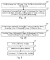
- Fig. 2B is a flow chart illustrating a process for defining a corresponding relationship.
- the step of defining a corresponding relationship between the values in the range and consumed lifespans includes the following steps.
- step 2041 the range is divided into 100 equal parts, to obtain a value of each of the parts.
- step 2042 a consumed lifespan in percentage for the value of each of the parts is determined according to a proportion of the value to the range, to obtain the corresponding relationship.
- the range is [2, 3], by dividing the range into 100 equal parts, a value of each of the parts can be obtained, respectively 2, 2.01, 2.02, ...., 2.98, 2.99 and 3.
- a consumed lifespan in percentage 0% is determined as corresponding to the value 2, 1% corresponding to 2.01, 2% corresponding to 2.02, ...., 98% corresponding to 2.98, 99% corresponding to 2.99 and 100% corresponding to 3.
- the consumed lifespans can be finely measured, achieving an effect of improving the accuracy of calculating consumed lifespans.
- steps 201-204 can be performed to define a corresponding relationship between the values of the sampled parameter and the consumed lifespans. They can be performed prior to the step 207, but the order of the steps 201-204 and the steps 205, 206 is not limited.
- step 205 an electric motor of a purifier is controlled to rotate at a predetermined speed.
- the predetermined speed in this step is the same as the speed manually adjusted by the user in step 201.
- the speed when calculating the consumed lifespans By keeping the speed when calculating the consumed lifespans the same as the speed when defining the corresponding relationship, it can eliminate the effect of the speed on the sampled parameter of the electric motor. Then, the dirty degree of the filter core is merely positive correlated to the size of the driving current of the electric motor. In this way, it can achieve an effect of improving the accuracy of calculating consumed lifespans.
- step 206 a value of a sampled parameter of the electric motor is acquired, the sampled parameter being at least one of a sampled current and a sampled voltage of the electric motor.
- the sample parameter is a sampled voltage of the electric motor
- the value of the sampled voltage can be directly acquired by a method known in the related art.
- the sample parameter is a sampled current of the electric motor
- Fig. 2C it shows a flow chart illustrating a process for acquiring a value of a sampled parameter.
- the step of acquiring a value of a sampled parameter of the electric motor includes the following steps.
- step 2061 when the sample parameter is a sampled current of the electric motor, a value of the sampled voltage of the electric motor is acquired.
- step 2062 the value of the sampled voltage is divided by a resistance of the electric motor to obtain the value of the sampled parameter.
- the resistance of the electric motor has a known value
- the value of the sample voltage can be directly acquired by a method known in the related art
- the value of the sampled voltage can be divided by the resistance to obtain the value of the sampled current, i.e. the sampled parameter.
- step 207 a pre-defined and pre-stored corresponding relationship between values of the sampled parameter and consumed lifespans is retrieved.
- step 208 a consumed lifespan corresponding to the acquired value of the sampled parameter is searched for in the corresponding relationship, wherein the consumed lifespan is in positive correlation with the acquired value of the sampled parameter.
- the consumed lifespan of the filter core can be determined as 54%.
- an electric motor of a purifier is controlled to rotate at a predetermined speed; a value of a sampled parameter of the electric motor is acquired, the sampled parameter being at least one of a sampled current and a sampled voltage of the electric motor; and a consumed lifespan of the purifier is determined according to the acquired value of the sampled parameter, wherein the consumed lifespan is in positive correlation with the acquired value of the sampled parameter.
- the speed when calculating the consumed lifespans the same as the speed when defining the corresponding relationship, it can eliminate the effect of the speed on the sampled parameter of the electric motor. Then, the dirty degree of the filter core is merely positively correlated to the size of the driving current of the electric motor. In this way, it can achieve an effect of improving the accuracy of calculating consumed lifespans.
- a corresponding relationship may be defined between the values of each of the 100 equal parts and consumed lifespans in percentages, the consumed lifespans can be finely measured, achieving an effect of improving the accuracy of calculating consumed lifespans.
- Fig. 3 is a block diagram illustrating a device for calculating a consumed lifespan according to an exemplary embodiment.
- the device for calculating a consumed lifespan is applied in a purifier.
- the device for calculating a consumed lifespan includes a first controlling module 310, a parameter acquiring module 320 and a consumed-life determining module 330.
- the first controlling module 310 is configured to control an electric motor of a purifier to rotate at a predetermined speed; the parameter acquiring module 320 is configured to acquire a value of a sampled parameter of the electric motor, the sampled parameter being at least one of a sampled current and a sampled voltage of the electric motor; and the consumed-life determining module 330 is configured to determine a consumed lifespan of the purifier according to the value of the sampled parameter obtained by the parameter acquiring module 320, wherein the consumed lifespan is in positive correlation with the acquired value of the sampled parameter.
- an electric motor of a purifier is controlled to rotate at a predetermined speed; a value of a sampled parameter of the electric motor is acquired, the sampled parameter being at least one of a sampled current and a sampled voltage of the electric motor; and a consumed lifespan of the purifier is determined according to the acquired value of the sampled parameter, wherein the consumed lifespan is in positive correlation with the acquired value of the sampled parameter.
- Fig. 4 is a block diagram illustrating a device for calculating a consumed lifespan according to an exemplary embodiment.
- the device for calculating a consumed lifespan is applied in a purifier.
- the device for calculating a consumed lifespan includes a first controlling module 410, a parameter acquiring module 420 and a consumed-life determining module 430.
- the first controlling module 410 is configured to control an electric motor of a purifier to rotate at a predetermined speed; the parameter acquiring module 420 is configured to acquire a value of a sampled parameter of the electric motor, the sampled parameter being at least one of a sampled current and a sampled voltage of the electric motor; and the consumed-life determining module 430 is configured to determine a consumed lifespan of the purifier according to the value of the sampled parameter obtained by the parameter acquiring module 420, wherein the consumed lifespan is in positive correlation with the acquired value of the sampled parameter.
- the consumed-life determining module 430 includes: a relationship retrieving sub-module 431 and a consumed-life searching sub-module 432.
- the relationship retrieving sub-module 431 is configured to retrieve a pre-defined and pre-stored corresponding relationship between values of the sampled parameter and consumed lifespans; and the consumed-life searching sub-module 432 is configured to search for a consumed lifespan corresponding to the acquired value of the sampled parameter in the corresponding relationship obtained by the relationship retrieving sub-module 431.
- the device for calculating a consumed lifespan further includes: a second controlling module 440, a parameter measuring module 450, a range determining module 460 and a relationship defining module 470.
- the second controlling module 440 is configured to control the electric motor of the purifier to rotate at the predetermined speed;
- the parameter measuring module 450 is configured to measure a maximum value and a minimum value of the sampled parameter of the electric motor, the maximum value of the sampled parameter being a value of the sampled parameter when the purifier is operated with a new filter core, and the minimum value of the sampled parameter being a value of the sampled parameter when the purifier is operated with the filter core reaching an end of its rated service life;
- the range determining module 460 is configured to determine a range between the maximum value and the minimum value of the sampled parameter obtained by the parameter measuring module 450; and the relationship defining module 470 is configured to define a corresponding relationship between the values in the range determined by the range determining module 460 and consumed lifespans.
- the relationship defining module 470 includes: a range equally-dividing sub-module 471 and a relationship defining sub-module 472.
- the range equally-dividing sub-module 471 is configured to divide the range into 100 equal parts, to obtain a value of each of the parts; and the relationship defining sub-module 472 is configured to determine a consumed lifespan in percentage for the value of each of the parts obtained by the range equally-dividing sub-module 471 according to a proportion of the value to the range, to obtain the corresponding relationship.
- the parameter acquiring module 420 includes: a voltage acquiring sub-module 421 and a parameter acquiring sub-module 422.
- the voltage acquiring sub-module 421 is configured to, when the sample parameter is a sampled current of the electric motor, acquire a value of the sampled voltage of the electric motor; and the parameter acquiring sub-module 422 is configured to divide the value of the sampled voltage obtained by the voltage acquiring sub-module 421 by a resistance of the electric motor to obtain the value of the sampled parameter.
- an electric motor of a purifier is controlled to rotate at a predetermined speed; a value of a sampled parameter of the electric motor is acquired, the sampled parameter being at least one of a sampled current and a sampled voltage of the electric motor; and a consumed lifespan of the purifier is determined according to the acquired value of the sampled parameter, wherein the consumed lifespan is in positive correlation with the acquired value of the sampled parameter.
- the speed when calculating the consumed lifespans the same as the speed when defining the corresponding relationship, it can eliminate the effect of the speed on the sampled parameter of the electric motor. Then, the dirty degree of the filter core is merely positive correlated to the size of the driving current of the electric motor. In this way, it can achieve an effect of improving the accuracy of calculating consumed lifespans.
- a corresponding relationship may be defined between the values of each of the 100 equal parts and consumed lifespans in percentages, the consumed lifespans can be finely measured, achieving an effect of improving the accuracy of calculating consumed lifespans.
- An exemplary embodiment of the present disclosure provides a device for calculating a consumed lifespan, which can implement the method for calculating a consumed lifespan provided by the present disclosure.
- the device for calculating a consumed lifespan includes :
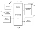
- Fig. 5 is a block diagram of a device 500 for purifying the air according to an exemplary embodiment.
- the device 500 may be a purifier, in particular, an air purifier.
- the device 500 may include one or more of the following components: a processing component 502, a memory 504, a power component 506, a purifier component 508, a sensor component 510, and a communication component 512.
- the processing component 502 typically controls overall operations of the device 500.
- the processing component 502 may include one or more processors 518 to execute instructions to perform all or part of the steps in the methods described in the above embodiments.
- the processing component 502 may include one or more modules which facilitate the interaction between the processing component 502 and other components. For instance, the processing component 502 may interact with the sensor component 510 and the communication component 512, and so on.
- the memory 504 is configured to store various types of data to support the operation of the device 500. Examples of such data include instructions for any applications or methods operated on the device 500, etc.
- the memory 504 may be implemented using any type of volatile or non-volatile memory devices, or a combination thereof, such as a static random access memory (SRAM), an electrically erasable programmable read-only memory (EEPROM), an erasable programmable read-only memory (EPROM), a programmable read-only memory (PROM), a read-only memory (ROM), a magnetic memory, a flash memory, a magnetic or optical disk.
- SRAM static random access memory
- EEPROM electrically erasable programmable read-only memory
- EPROM erasable programmable read-only memory
- PROM programmable read-only memory
- ROM read-only memory
- magnetic memory a magnetic memory
- flash memory a flash memory
- magnetic or optical disk a magnetic or optical disk.
- the power component 506 provides power to various components of the device 500.
- the power component 506 may include a power management system, one or more power sources, and any other components associated with the generation, management, and distribution of power in the device 500.
- the purifier component 508 includes an electric motor and is configured to purify the air sucked in and discharge the purified air. In one possible implementation, the purifier component 508 purifies the air by absorbing harmful substances in the air. In another possible implementation, the purifier component 508 purifies the air by releasing negative oxygen ions. However, the purifier component 508 can also purify the air by other means, which will be elaborated herein.
- the sensor component 510 includes one or more sensors to provide status assessments of various aspects of the device 500. For instance, the sensor component 510 may detect concentration of dust in the air.
- the communication component 512 is configured to facilitate communication, wired or wirelessly, between the device 500 and other devices.
- the device 500 can access a wireless network based on a communication standard, such as WiFi, 2G, or 3G, or a combination thereof.
- the communication component 512 receives a broadcast signal or broadcast associated information from an external broadcast management system via a broadcast channel.
- the communication component 512 further includes a near field communication (NFC) module to facilitate short-range communications.
- the NFC module may be implemented based on a radio frequency identification (RFID) technology, an infrared data association (IrDA) technology, an ultra-wideband (UWB) technology, a Bluetooth (BT) technology, and other technologies.
- RFID radio frequency identification
- IrDA infrared data association
- UWB ultra-wideband
- BT Bluetooth
- the device 500 may be implemented with one or more application specific integrated circuits (ASICs), digital signal processors (DSPs), digital signal processing devices (DSPDs), programmable logic devices (PLDs), field programmable gate arrays (FPGAs), controllers, micro-controllers, microprocessors, or other electronic components, for performing the above described methods.
- ASICs application specific integrated circuits
- DSPs digital signal processors
- DSPDs digital signal processing devices
- PLDs programmable logic devices
- FPGAs field programmable gate arrays
- controllers micro-controllers, microprocessors, or other electronic components, for performing the above described methods.
- non-transitory computer-readable storage medium including instructions, such as included in the memory 504, executable by the processor 518 in the device 500, for performing the above-described methods.
- the non-transitory computer-readable storage medium may be a ROM, a RAM, a CD-ROM, a magnetic tape, a floppy disc, an optical data storage device, and the like.
- modules are referred to in apparatus embodiments for carrying out various steps of the described method(s) it will be understood that these modules may be implemented in hardware, in software, or a combination of the two.
- the modules When implemented in hardware, the modules may be implemented as one or more hardware modules, such as one or more application specific integrated circuits.
- the modules When implemented in software, the modules may be implemented as one or more computer programs that are executed on one or more processors.
Landscapes
- Chemical & Material Sciences (AREA)
- Engineering & Computer Science (AREA)
- Chemical Kinetics & Catalysis (AREA)
- Physics & Mathematics (AREA)
- General Physics & Mathematics (AREA)
- Combustion & Propulsion (AREA)
- Mechanical Engineering (AREA)
- General Engineering & Computer Science (AREA)
- Automation & Control Theory (AREA)
- Life Sciences & Earth Sciences (AREA)
- Health & Medical Sciences (AREA)
- Analytical Chemistry (AREA)
- Biochemistry (AREA)
- General Health & Medical Sciences (AREA)
- Immunology (AREA)
- Pathology (AREA)
- Dispersion Chemistry (AREA)
- Control Of Electric Motors In General (AREA)
- Air Conditioning Control Device (AREA)
- Testing Electric Properties And Detecting Electric Faults (AREA)
- Ventilation (AREA)
Abstract
Description
- The present disclosure generally relates to the field of purifiers, and more particularly, to a method and a device for calculating a consumed lifespan.
- A filter core in an air purifier has a limited service life. The filter core has to be replaced in time when the filter core is stuck with dirt, to ensure the air purifying effect.
- In a related art, when the purifier is operated at various levels of power, in order to calculate a current consumed lifespan, a service time period at each level of power is recorded, the recorded service time periods are respectively multiplied with corresponding coefficients, and the products are summed up as the current consumed lifespan.
- In order to solve the problem in the related art, the present disclosure provides a method and a device for calculating a consumed lifespan.
- According to a first aspect of embodiments of the present disclosure, there is provided a method for calculating a consumed lifespan, including the followings steps:
- controlling an electric motor of a purifier to rotate at a predetermined speed;
- acquiring a value of a sampled parameter of the electric motor, the sampled parameter being at least one of a sampled current and a sampled voltage of the electric motor; and
- determining a consumed lifespan of the purifier according to the acquired value of the sampled parameter, wherein the consumed lifespan is in positive correlation with the acquired value of the sampled parameter.
- Optionally, the step of determining a consumed lifespan of the purifier according to the acquired value of the sampled parameter includes:
- retrieving a pre-defined and pre-stored corresponding relationship between values of the sampled parameter and consumed lifespans; and
- searching for a consumed lifespan corresponding to the acquired value of the sampled parameter in the corresponding relationship.
- Optionally, the method further includes the following steps:
- controlling the electric motor of the purifier to rotate at the predetermined speed;
- measuring a maximum value and a minimum value of the sampled parameter of the electric motor, the maximum value of the sampled parameter being a value of the sampled parameter when the purifier is operated with a new filter core, and the minimum value of the sampled parameter being a value of the sampled parameter when the purifier is operated with the filter core reaching an end of its rated service life;
- determining a range between the maximum value and the minimum value of the sampled parameter; and
- defining a corresponding relationship between the values in the range and consumed lifespans.
- Optionally, when the consumed lifespans are indicated in percentages, the step of defining a corresponding relationship between the values in the range and consumed lifespans includes:
- dividing the range into 100 equal parts, to obtain a value of each of the parts; and
- determining a consumed lifespan in percentage for the value of each of the parts according to a proportion of the value to the range, to obtain the corresponding relationship.
- Optionally, the step of acquiring a value of a sampled parameter of the electric motor includes:
- when the sample parameter is a sampled current of the electric motor, acquiring a value of the sampled voltage of the electric motor; and
- dividing the value of the sampled voltage by a resistance of the electric motor to obtain the value of the sampled parameter.
- According to a second aspect of embodiments of the present disclosure, there is provided a device for calculating a consumed lifespan, including:
- a first controlling module configured to control an electric motor of a purifier to rotate at a predetermined speed;
- a parameter acquiring module configured to acquire a value of a sampled parameter of the electric motor, the sampled parameter being at least one of a sampled current and a sampled voltage of the electric motor; and
- a consumed-life determining module configured to determine a consumed lifespan of the purifier according to the value of the sampled parameter obtained by the parameter acquiring module, wherein the consumed lifespan is in positive correlation with the acquired value of the sampled parameter.
- Optionally, the consumed-life determining module includes:
- a relationship retrieving sub-module configured to retrieve a pre-defined and pre-stored corresponding relationship between values of the sampled parameter and consumed lifespans; and
- a consumed-life searching sub-module configured to search for a consumed lifespan corresponding to the acquired value of the sampled parameter in the corresponding relationship obtained by the relationship retrieving sub-module.
- Optionally, the device further includes:
- a second controlling module configured to control the electric motor of the purifier to rotate at the predetermined speed;
- a parameter measuring module configured to measure a maximum value and a minimum value of the sampled parameter of the electric motor, the maximum value of the sampled parameter being a value of the sampled parameter when the purifier is operated with a new filter core, and the minimum value of the sampled parameter being a value of the sampled parameter when the purifier is operated with the filter core reaching an end of its rated service life;
- a range determining module configured to determine a range between the maximum value and the minimum value of the sampled parameter obtained by the parameter measuring module; and
- a relationship defining module configured to define a corresponding relationship between the values in the range determined by the range determining module and consumed lifespans.
- Optionally, when the consumed lifespans are indicated in percentages, the relationship defining module includes:
- a range equally-dividing sub-module configured to divide the range into 100 equal parts, to obtain a value of each of the parts; and
- a relationship defining sub-module configured to determine a consumed lifespan in percentage for the value of each of the parts obtained by the range equally-dividing sub-module according to a proportion of the value to the range, to obtain the corresponding relationship.
- Optionally, the parameter acquiring module includes:
- a voltage acquiring sub-module configured to, when the sample parameter is a sampled current of the electric motor, acquire a value of the sampled voltage of the electric motor; and
- a parameter acquiring sub-module configured to divide the value of the sampled voltage obtained by the voltage acquiring sub-module by a resistance of the electric motor to obtain the value of the sampled parameter.
- According to a third aspect of embodiments of the present disclosure, there is provided a device for calculating a consumed lifespan, including:
- a processor; and
- a memory for storing instructions executable by the processor;
- controlling an electric motor of a purifier to rotate at a predetermined speed;
- acquiring a value of a sampled parameter of the electric motor, the sampled parameter being at least one of a sampled current and a sampled voltage of the electric motor; and
- determining a consumed lifespan of the purifier according to the acquired value of the sampled parameter, wherein the consumed lifespan is in positive correlation with the acquired value of the sampled parameter.
- According to a fourth aspect of the embodiment of the present disclosure, there is provided a program product, having stored therein instructions that, when executed by one or more processors of a purifier, causes the purifier to perform the method according to the first aspect.
- According to a fifth aspect of the embodiment of the present disclosure, there is provided a computer program which, when being executed on a processor of a purifier, performs the above method according to the first aspect.
- The technical solution according to embodiments of the present disclosure may have the following beneficial effects.
- An electric motor of a purifier is controlled to rotate at a predetermined speed; a value of a sampled parameter of the electric motor is acquired, the sampled parameter being at least one of a sampled current and a sampled voltage of the electric motor; and a consumed lifespan of the purifier is determined according to the acquired value of the sampled parameter, wherein the consumed lifespan is in positive correlation with the acquired value of the sampled parameter. Thereby, based on the principle that the dirty degree of the filter core is in positive correlation with the size of the driving current of the electric motor, the dirty degree of the filter core can be determined according to the value of the sampled parameter of the electric motor, and in turn, the consumed lifespan of the filter core can be determined. In this way, it can avoid the problem that it is inaccurate to determine the consumed lifespans according to the service time periods, and it can achieve an effect of improving the accuracy of calculating consumed lifespans.
- In addition, by keeping the speed when calculating the consumed lifespans the same as the speed when defining the corresponding relationship, it can eliminate the effect of the speed on the sampled parameter of the electric motor. Then, the dirty degree of the filter core is merely positive correlated to the size of the driving current of the electric motor. In this way, it can achieve an effect of improving the accuracy of calculating consumed lifespans.
- Further, by dividing the range into 100 equal parts to obtain a value of each of the parts, and determining a consumed lifespan in percentage for the value of each of the parts according to a proportion of the value to the range, to obtain the corresponding relationship, a corresponding relationship may be defined between the values of each of the 100 equal parts and consumed lifespans in percentages, the consumed lifespans can be finely measured, achieving an effect of improving the accuracy of calculating consumed lifespans.
- It is to be understood that both the foregoing general description and the following detailed description are exemplary only and are not restrictive of the present disclosure.
- The accompanying drawings, which are incorporated in and constitute a part of this specification, illustrate embodiments consistent with the present disclosure and, together with the description, serve to explain the principles of the present disclosure.
-
Fig. 1 is a flow chart illustrating a method for calculating a consumed lifespan according to an exemplary embodiment. -
Fig. 2A is a flow chart illustrating a method for calculating a consumed lifespan according to another exemplary embodiment. -
Fig. 2B is a flow chart illustrating a process for defining a corresponding relationship according to the exemplary embodiment. -
Fig. 2C is a flow chart illustrating a process for acquiring a value of a sampled parameter according to the exemplary embodiment. -
Fig. 3 is a block diagram illustrating a device for calculating a consumed lifespan according to an exemplary embodiment. -
Fig. 4 is a block diagram illustrating a device for calculating a consumed lifespan according to an exemplary embodiment. -
Fig. 5 is a block diagram illustrating a device for calculating a consumed lifespan according to an exemplary embodiment. - Reference will now be made in detail to exemplary embodiments, examples of which are illustrated in the accompanying drawings. The following description refers to the accompanying drawings in which the same numbers in different drawings represent the same or similar elements unless otherwise represented. The implementations set forth in the following description of exemplary embodiments do not represent all implementations consistent with the present disclosure. Instead, they are merely examples of devices and methods consistent with aspects related to the present disclosure as recited in the appended claims.
-
Fig. 1 is a flow chart illustrating a method for calculating a consumed lifespan according to an exemplary embodiment, which is applied in a purifier, and, in particular, an air purifier. As shown inFig. 1 , the method for calculating a consumed lifespan includes the following steps. - In
step 101, an electric motor of a purifier is controlled to rotate at a predetermined speed. - In
step 102, a value of a sampled parameter of the electric motor is acquired, the sampled parameter being at least one of a sampled current and a sampled voltage of the electric motor. - In
step 103, a consumed lifespan of the purifier is determined according to the acquired value of the sampled parameter, wherein the consumed lifespan is in positive correlation with the acquired value of the sampled parameter. - Accordingly, in the method for calculating a consumed lifespan provided by the present disclosure, an electric motor of a purifier is controlled to rotate at a predetermined speed; a value of a sampled parameter of the electric motor is acquired, the sampled parameter being at least one of a sampled current and a sampled voltage of the electric motor; and a consumed lifespan of the purifier is determined according to the acquired value of the sampled parameter, wherein the consumed lifespan is in positive correlation with the acquired value of the sampled parameter. Thereby, based on the principle that the dirty degree of the filter core is in positive correlation with the size of the driving current of the electric motor, the dirty degree of the filter core can be determined according to the value of the sampled parameter of the electric motor, and in turn, the consumed lifespan of the filter core can be determined. In this way, it can avoid the problem that it is inaccurate to determine the consumed lifespans according to the service time periods, and it can achieve an effect of improving the accuracy of calculating consumed lifespans.
-
Fig. 2A is a flow chart illustrating a method for calculating a consumed lifespan according to another exemplary embodiment, which is applied in a purifier. As shown inFig. 2A , the method for calculating a consumed lifespan includes the following steps. - In
step 201, an electric motor of a purifier is controlled to rotate at a predetermined speed. - The purifier can be controlled to purify the air by driving the electric motor of the purifier at different speeds. The higher the speed of the electric motor, the larger the driving current of the electric motor is.
- In this embodiment, a user can manually adjust the speed of the electric motor to any value, and the purifier determines the value as the predetermined speed.
- In
step 202, a maximum value and a minimum value of the sampled parameter of the electric motor are measured, the maximum value of the sampled parameter being a value of the sampled parameter when the purifier is operated with a new filter core, and the minimum value of the sampled parameter being a value of the sampled parameter when the purifier is operated with the filter core reaching an end of its rated service life. - When the purifier is operated with a new filter core, the air path of the filter core is smooth. Then, the driving current of the electric motor can be small. After the filter core has been put into operation for a while, the filter core can be stuck with dirt since impurities in the air to be purified can be trapped in the filter core, such that the air path of the filter core can be less smooth than before. At this time, the driving current of the electric motor can be larger. In this regard, the dirty degree of the filter core is in positive correlation with the size of the driving current. That is, the longer the consumed lifespan is, the more dirty the filter core is, and the larger the driving current is. Based on this principle, a corresponding relationship between consumed lifespans of the purifier and values of the driving currents can be previously defined.
- Since a voltage is a product of a current value multiplying with a resistance, the consumed lifespan of the purifier can be determined according to the voltage of the electric motor. Here, the voltage is a sampled voltage of the electric motor, rather than a rated voltage of the electric motor. Hereinafter, the driving current and the driving voltage will be collectively referred to as sampled parameters.
- To define a corresponding relationship between values of the sampled parameter and consumed lifespans, a value of the sampled parameter is measured when the purifier is operated with a new filter core, and this value is taken as a minimum value of the sampled parameter. Then, a value of the sampled parameter is measured when the purifier is operated with the filter core reaching an end of its rated service life, and this value is taken as a maximum value of the sampled parameter. Here, the technology for measuring the sampled parameter of the electric motor is well known, and will not be repeated in this embodiment.
- In
step 203, a range between the maximum value and the minimum value of the sampled parameter is determined. - For example, when the sampled parameter is the current, it is assumed that the maximum value of the sampled parameter is 3A, and the minimum value of the sampled parameter is 2A, then the range is determined as [2, 3].
- In
step 204, a corresponding relationship between the values in the range and consumed lifespans is defined. - In this embodiment, a calculation formula of the values and the consumed lifespans can be generated, or a corresponding relationship between values and consumed lifespans can be formed, or by other means, which will not be limited in this embodiment.
-
Fig. 2B is a flow chart illustrating a process for defining a corresponding relationship. When the consumed lifespans are indicated in percentages, the step of defining a corresponding relationship between the values in the range and consumed lifespans includes the following steps. - In
step 2041, the range is divided into 100 equal parts, to obtain a value of each of the parts. - In
step 2042, a consumed lifespan in percentage for the value of each of the parts is determined according to a proportion of the value to the range, to obtain the corresponding relationship. - For example, the range is [2, 3], by dividing the range into 100 equal parts, a value of each of the parts can be obtained, respectively 2, 2.01, 2.02, ...., 2.98, 2.99 and 3. A consumed lifespan in percentage 0% is determined as corresponding to the value 2, 1% corresponding to 2.01, 2% corresponding to 2.02, ...., 98% corresponding to 2.98, 99% corresponding to 2.99 and 100% corresponding to 3.
- By dividing the range into 100 equal parts to obtain a value of each of the parts, and defining a corresponding relationship between the values of the parts and percentages, the consumed lifespans can be finely measured, achieving an effect of improving the accuracy of calculating consumed lifespans.
- Here, the process of steps 201-204 can be performed to define a corresponding relationship between the values of the sampled parameter and the consumed lifespans. They can be performed prior to the
step 207, but the order of the steps 201-204 and thesteps - In
step 205, an electric motor of a purifier is controlled to rotate at a predetermined speed. - The predetermined speed in this step is the same as the speed manually adjusted by the user in
step 201. - By keeping the speed when calculating the consumed lifespans the same as the speed when defining the corresponding relationship, it can eliminate the effect of the speed on the sampled parameter of the electric motor. Then, the dirty degree of the filter core is merely positive correlated to the size of the driving current of the electric motor. In this way, it can achieve an effect of improving the accuracy of calculating consumed lifespans.
- In
step 206, a value of a sampled parameter of the electric motor is acquired, the sampled parameter being at least one of a sampled current and a sampled voltage of the electric motor. - When the sample parameter is a sampled voltage of the electric motor, the value of the sampled voltage can be directly acquired by a method known in the related art. When the sample parameter is a sampled current of the electric motor, referring to
Fig. 2C , it shows a flow chart illustrating a process for acquiring a value of a sampled parameter. Here, the step of acquiring a value of a sampled parameter of the electric motor includes the following steps. - In
step 2061, when the sample parameter is a sampled current of the electric motor, a value of the sampled voltage of the electric motor is acquired. - In
step 2062, the value of the sampled voltage is divided by a resistance of the electric motor to obtain the value of the sampled parameter. - Since the resistance of the electric motor has a known value, and the value of the sample voltage can be directly acquired by a method known in the related art, then the value of the sampled voltage can be divided by the resistance to obtain the value of the sampled current, i.e. the sampled parameter.
- In
step 207, a pre-defined and pre-stored corresponding relationship between values of the sampled parameter and consumed lifespans is retrieved. - In
step 208, a consumed lifespan corresponding to the acquired value of the sampled parameter is searched for in the corresponding relationship, wherein the consumed lifespan is in positive correlation with the acquired value of the sampled parameter. - For example, it is assumed that the value of the sample parameter is 2.54A and in the corresponding relationship, the value 2.54 corresponds to a percentage 54%, then, the consumed lifespan of the filter core can be determined as 54%.
- Accordingly, in the method for calculating a consumed lifespan provided by the present disclosure, an electric motor of a purifier is controlled to rotate at a predetermined speed; a value of a sampled parameter of the electric motor is acquired, the sampled parameter being at least one of a sampled current and a sampled voltage of the electric motor; and a consumed lifespan of the purifier is determined according to the acquired value of the sampled parameter, wherein the consumed lifespan is in positive correlation with the acquired value of the sampled parameter. Thereby, based on the principle that the dirty degree of the filter core is in positive correlation with the size of the driving current of the electric motor, the dirty degree of the filter core can be determined according to the value of the sampled parameter of the electric motor, and in turn, the consumed lifespan of the filter core can be determined. In this way, it can avoid the problem that it is inaccurate to determine the consumed lifespans according to the service time periods, and it can achieve an effect of improving the accuracy of calculating consumed lifespans.
- In addition, by keeping the speed when calculating the consumed lifespans the same as the speed when defining the corresponding relationship, it can eliminate the effect of the speed on the sampled parameter of the electric motor. Then, the dirty degree of the filter core is merely positively correlated to the size of the driving current of the electric motor. In this way, it can achieve an effect of improving the accuracy of calculating consumed lifespans.
- Further, by dividing the range into 100 equal parts to obtain a value of each of the parts, and determining a consumed lifespan in percentage for the value of each of the parts according to a proportion of the value to the range, to obtain the corresponding relationship, a corresponding relationship may be defined between the values of each of the 100 equal parts and consumed lifespans in percentages, the consumed lifespans can be finely measured, achieving an effect of improving the accuracy of calculating consumed lifespans.
-
Fig. 3 is a block diagram illustrating a device for calculating a consumed lifespan according to an exemplary embodiment. The device for calculating a consumed lifespan is applied in a purifier. As shown inFig. 3 , the device for calculating a consumed lifespan includes afirst controlling module 310, aparameter acquiring module 320 and a consumed-life determining module 330. - The
first controlling module 310 is configured to control an electric motor of a purifier to rotate at a predetermined speed;
theparameter acquiring module 320 is configured to acquire a value of a sampled parameter of the electric motor, the sampled parameter being at least one of a sampled current and a sampled voltage of the electric motor; and
the consumed-life determining module 330 is configured to determine a consumed lifespan of the purifier according to the value of the sampled parameter obtained by theparameter acquiring module 320, wherein the consumed lifespan is in positive correlation with the acquired value of the sampled parameter. - Accordingly, in the device for calculating a consumed lifespan provided by the present disclosure, an electric motor of a purifier is controlled to rotate at a predetermined speed; a value of a sampled parameter of the electric motor is acquired, the sampled parameter being at least one of a sampled current and a sampled voltage of the electric motor; and a consumed lifespan of the purifier is determined according to the acquired value of the sampled parameter, wherein the consumed lifespan is in positive correlation with the acquired value of the sampled parameter. Thereby, based on the principle that the dirty degree of the filter core is in positive correlation with the size of the driving current of the electric motor, the dirty degree of the filter core can be determined according to the value of the sampled parameter of the electric motor, and in turn, the consumed lifespan of the filter core can be determined. In this way, it can avoid the problem that it is inaccurate to determine the consumed lifespans according to the service time periods, and it can achieve an effect of improving the accuracy of calculating consumed lifespans.
-
Fig. 4 is a block diagram illustrating a device for calculating a consumed lifespan according to an exemplary embodiment. The device for calculating a consumed lifespan is applied in a purifier. As shown inFig. 4 , the device for calculating a consumed lifespan includes afirst controlling module 410, aparameter acquiring module 420 and a consumed-life determining module 430. - The
first controlling module 410 is configured to control an electric motor of a purifier to rotate at a predetermined speed;
theparameter acquiring module 420 is configured to acquire a value of a sampled parameter of the electric motor, the sampled parameter being at least one of a sampled current and a sampled voltage of the electric motor; and
the consumed-life determining module 430 is configured to determine a consumed lifespan of the purifier according to the value of the sampled parameter obtained by theparameter acquiring module 420, wherein the consumed lifespan is in positive correlation with the acquired value of the sampled parameter. - Optionally, the consumed-
life determining module 430 includes: a relationship retrieving sub-module 431 and a consumed-life searching sub-module 432. - The relationship retrieving sub-module 431 is configured to retrieve a pre-defined and pre-stored corresponding relationship between values of the sampled parameter and consumed lifespans; and
the consumed-life searching sub-module 432 is configured to search for a consumed lifespan corresponding to the acquired value of the sampled parameter in the corresponding relationship obtained by therelationship retrieving sub-module 431. - Optionally, the device for calculating a consumed lifespan further includes: a
second controlling module 440, aparameter measuring module 450, arange determining module 460 and arelationship defining module 470. - The
second controlling module 440 is configured to control the electric motor of the purifier to rotate at the predetermined speed;
theparameter measuring module 450 is configured to measure a maximum value and a minimum value of the sampled parameter of the electric motor, the maximum value of the sampled parameter being a value of the sampled parameter when the purifier is operated with a new filter core, and the minimum value of the sampled parameter being a value of the sampled parameter when the purifier is operated with the filter core reaching an end of its rated service life;
therange determining module 460 is configured to determine a range between the maximum value and the minimum value of the sampled parameter obtained by theparameter measuring module 450; and
therelationship defining module 470 is configured to define a corresponding relationship between the values in the range determined by therange determining module 460 and consumed lifespans. - Optionally, when the consumed lifespans are indicated in percentages, the
relationship defining module 470 includes: a range equally-dividingsub-module 471 and arelationship defining sub-module 472. - The range equally-dividing
sub-module 471 is configured to divide the range into 100 equal parts, to obtain a value of each of the parts; and
the relationship defining sub-module 472 is configured to determine a consumed lifespan in percentage for the value of each of the parts obtained by the range equally-dividing sub-module 471 according to a proportion of the value to the range, to obtain the corresponding relationship. - Optionally, the
parameter acquiring module 420 includes: a voltage acquiring sub-module 421 and a parameter acquiring sub-module 422. - The voltage acquiring sub-module 421 is configured to, when the sample parameter is a sampled current of the electric motor, acquire a value of the sampled voltage of the electric motor; and
the parameter acquiring sub-module 422 is configured to divide the value of the sampled voltage obtained by the voltage acquiring sub-module 421 by a resistance of the electric motor to obtain the value of the sampled parameter. - Accordingly, in the device for calculating a consumed lifespan provided by the present disclosure, an electric motor of a purifier is controlled to rotate at a predetermined speed; a value of a sampled parameter of the electric motor is acquired, the sampled parameter being at least one of a sampled current and a sampled voltage of the electric motor; and a consumed lifespan of the purifier is determined according to the acquired value of the sampled parameter, wherein the consumed lifespan is in positive correlation with the acquired value of the sampled parameter. Thereby, based on the principle that the dirty degree of the filter core is in positive correlation with the size of the driving current of the electric motor, the dirty degree of the filter core can be determined according to the value of the sampled parameter of the electric motor, and in turn, the consumed lifespan of the filter core can be determined. In this way, it can avoid the problem that it is inaccurate to determine the consumed lifespans according to the service time periods, and it can achieve an effect of improving the accuracy of calculating consumed lifespans.
- In addition, by keeping the speed when calculating the consumed lifespans the same as the speed when defining the corresponding relationship, it can eliminate the effect of the speed on the sampled parameter of the electric motor. Then, the dirty degree of the filter core is merely positive correlated to the size of the driving current of the electric motor. In this way, it can achieve an effect of improving the accuracy of calculating consumed lifespans.
- Further, by dividing the range into 100 equal parts to obtain a value of each of the parts, and determining a consumed lifespan in percentage for the value of each of the parts according to a proportion of the value to the range, to obtain the corresponding relationship, a corresponding relationship may be defined between the values of each of the 100 equal parts and consumed lifespans in percentages, the consumed lifespans can be finely measured, achieving an effect of improving the accuracy of calculating consumed lifespans.
- With respect to the devices in the above embodiments, the specific manners for performing operations for individual modules therein have been described in detail in the embodiments regarding the relevant methods, which will not be elaborated herein.
- An exemplary embodiment of the present disclosure provides a device for calculating a consumed lifespan, which can implement the method for calculating a consumed lifespan provided by the present disclosure. The device for calculating a consumed lifespan includes :
- a processor; and
- a memory for storing instructions executable by the processor;
- controlling an electric motor of a purifier to rotate at a predetermined speed;
- acquiring a value of a sampled parameter of the electric motor, the sampled parameter being at least one of a sampled current and a sampled voltage of the electric motor; and
- determining a consumed lifespan of the purifier according to the acquired value of the sampled parameter, wherein the consumed lifespan is in positive correlation with the acquired value of the sampled parameter.
-
Fig. 5 is a block diagram of adevice 500 for purifying the air according to an exemplary embodiment. For example, thedevice 500 may be a purifier, in particular, an air purifier. - Referring to
Fig. 5 , thedevice 500 may include one or more of the following components: aprocessing component 502, amemory 504, apower component 506, apurifier component 508, asensor component 510, and acommunication component 512. - The
processing component 502 typically controls overall operations of thedevice 500. Theprocessing component 502 may include one ormore processors 518 to execute instructions to perform all or part of the steps in the methods described in the above embodiments. Moreover, theprocessing component 502 may include one or more modules which facilitate the interaction between theprocessing component 502 and other components. For instance, theprocessing component 502 may interact with thesensor component 510 and thecommunication component 512, and so on. - The
memory 504 is configured to store various types of data to support the operation of thedevice 500. Examples of such data include instructions for any applications or methods operated on thedevice 500, etc. Thememory 504 may be implemented using any type of volatile or non-volatile memory devices, or a combination thereof, such as a static random access memory (SRAM), an electrically erasable programmable read-only memory (EEPROM), an erasable programmable read-only memory (EPROM), a programmable read-only memory (PROM), a read-only memory (ROM), a magnetic memory, a flash memory, a magnetic or optical disk. - The
power component 506 provides power to various components of thedevice 500. Thepower component 506 may include a power management system, one or more power sources, and any other components associated with the generation, management, and distribution of power in thedevice 500. - The
purifier component 508 includes an electric motor and is configured to purify the air sucked in and discharge the purified air. In one possible implementation, thepurifier component 508 purifies the air by absorbing harmful substances in the air. In another possible implementation, thepurifier component 508 purifies the air by releasing negative oxygen ions. However, thepurifier component 508 can also purify the air by other means, which will be elaborated herein. - The
sensor component 510 includes one or more sensors to provide status assessments of various aspects of thedevice 500. For instance, thesensor component 510 may detect concentration of dust in the air. - The
communication component 512 is configured to facilitate communication, wired or wirelessly, between thedevice 500 and other devices. Thedevice 500 can access a wireless network based on a communication standard, such as WiFi, 2G, or 3G, or a combination thereof. In one exemplary embodiment, thecommunication component 512 receives a broadcast signal or broadcast associated information from an external broadcast management system via a broadcast channel. In one exemplary embodiment, thecommunication component 512 further includes a near field communication (NFC) module to facilitate short-range communications. For example, the NFC module may be implemented based on a radio frequency identification (RFID) technology, an infrared data association (IrDA) technology, an ultra-wideband (UWB) technology, a Bluetooth (BT) technology, and other technologies. - In exemplary embodiments, the
device 500 may be implemented with one or more application specific integrated circuits (ASICs), digital signal processors (DSPs), digital signal processing devices (DSPDs), programmable logic devices (PLDs), field programmable gate arrays (FPGAs), controllers, micro-controllers, microprocessors, or other electronic components, for performing the above described methods. - In exemplary embodiments, there is also provided a non-transitory computer-readable storage medium including instructions, such as included in the
memory 504, executable by theprocessor 518 in thedevice 500, for performing the above-described methods. For example, the non-transitory computer-readable storage medium may be a ROM, a RAM, a CD-ROM, a magnetic tape, a floppy disc, an optical data storage device, and the like. - Where functional modules are referred to in apparatus embodiments for carrying out various steps of the described method(s) it will be understood that these modules may be implemented in hardware, in software, or a combination of the two. When implemented in hardware, the modules may be implemented as one or more hardware modules, such as one or more application specific integrated circuits. When implemented in software, the modules may be implemented as one or more computer programs that are executed on one or more processors.
- It will be appreciated that the present invention is not limited to the exact construction that has been described above and illustrated in the accompanying drawings, and that various modifications and changes can be made without departing from the scope thereof. It is intended that the scope of the invention only be limited by the appended claims.
Claims (14)
- A method for calculating a consumed lifespan, the method comprising:controlling (101, 205) an electric motor of a purifier to rotate at a predetermined speed;acquiring (102, 206) a value of a sampled parameter of the electric motor, the sampled parameter being at least one of a sampled current and a sampled voltage of the electric motor; anddetermining (103) a consumed lifespan of the purifier according to the acquired value of the sampled parameter, wherein the consumed lifespan is in positive correlation with the acquired value of the sampled parameter.
- The method of claim 1, characterized in that the step of determining (103) a consumed lifespan of the purifier according to the acquired value of the sampled parameter comprises:retrieving (207) a pre-defined and pre-stored corresponding relationship between values of the sampled parameter and consumed lifespans; andsearching (208) for a consumed lifespan corresponding to the acquired value of the sampled parameter in the corresponding relationship.
- The method of claim 1 or claim 2, characterized in that the method further comprises:controlling (201) the electric motor of the purifier to rotate at the predetermined speed;measuring (202) a maximum value and a minimum value of the sampled parameter of the electric motor, the maximum value of the sampled parameter being a value of the sampled parameter when the purifier is operated with a new filter core, and the minimum value of the sampled parameter being a value of the sampled parameter when the purifier is operated with the filter core reaching an end of its rated service life;determining (203) a range between the maximum value and the minimum value of the sampled parameter; anddefining (204) a corresponding relationship between the values in the range andconsumed lifespans.
- The method of claim 3, characterized in that when the consumed lifespans are indicated in percentages, the step of defining (204) a corresponding relationship between the values in the range and consumed lifespans comprises:dividing (2041) the range into 100 equal parts, to obtain a value of each of the parts; anddetermining (2042) a consumed lifespan in percentage for the value of each of the parts according to a proportion of the value to the range, to obtain the corresponding relationship.
- The method of any of claims 1-4, characterized in that the step of acquiring (102, 206) a value of a sampled parameter of the electric motor comprises:when the sample parameter is a sampled current of the electric motor, acquiring (2061) a value of the sampled voltage of the electric motor; anddividing (2062) the value of the sampled voltage by a resistance of the electric motor to obtain the value of the sampled parameter.
- A device for calculating a consumed lifespan, the device comprising:a first controlling module (310, 410) configured to control an electric motor of a purifier to rotate at a predetermined speed;a parameter acquiring module (320, 420) configured to acquire a value of a sampled parameter of the electric motor, the sampled parameter being at least one of a sampled current and a sampled voltage of the electric motor; anda consumed-life determining module (330, 430) configured to determine a consumed lifespan of the purifier according to the value of the sampled parameter obtained by the parameter acquiring module, wherein the consumed lifespan is in positive correlation with the acquired value of the sampled parameter.
- The device of claim 6, characterized in that the consumed-life determining module (330, 430) comprises:a relationship retrieving sub-module (431) configured to retrieve a pre-defined and pre-stored corresponding relationship between values of the sampled parameter and consumed lifespans; anda consumed-life searching sub-module (432) configured to search for a consumed lifespan corresponding to the acquired value of the sampled parameter in the corresponding relationship obtained by the relationship retrieving sub-module.
- The device of claim 6 or claim 7, characterized in that the device further comprises:a second controlling module (440) configured to control the electric motor of the purifier to rotate at the predetermined speed;a parameter measuring module (450) configured to measure a maximum value and a minimum value of the sampled parameter of the electric motor, the maximum value of the sampled parameter being a value of the sampled parameter when the purifier is operated with a new filter core, and the minimum value of the sampled parameter being a value of the sampled parameter when the purifier is operated with the filter core reaching an end of its rated service life;a range determining module (460) configured to determine a range between the maximum value and the minimum value of the sampled parameter obtained by the parameter measuring module; anda relationship defining module (470) configured to define a corresponding relationship between the values in the range determined by the range determining module and consumed lifespans.
- The device of claim 8, characterized in that when the consumed lifespans are indicated in percentages, the relationship defining module (470) comprises:a range equally-dividing sub-module (471) configured to divide the range into 100 equal parts, to obtain a value of each of the parts; anda relationship defining sub-module (472) configured to determine a consumed lifespan in percentage for the value of each of the parts obtained by the range equally-dividing sub-module according to a proportion of the value to the range, to obtain the corresponding relationship.
- The device of any of claims 6-9, characterized in that the parameter acquiring module (320, 420) comprises:a voltage acquiring sub-module (421) configured to, when the sample parameter is a sampled current of the electric motor, acquire a value of the sampled voltage of the electric motor; anda parameter acquiring sub-module (422) configured to divide the value of the sampled voltage obtained by the voltage acquiring sub-module by a resistance of the electric motor to obtain the value of the sampled parameter.
- A device for calculating a consumed lifespan, the device comprising:a processor; anda memory for storing instructions executable by the processor;wherein the processor is configured to perform:controlling an electric motor of a purifier to rotate at a predetermined speed;acquiring a value of a sampled parameter of the electric motor, the sampled parameter being at least one of a sampled current and a sampled voltage of the electric motor; anddetermining a consumed lifespan of the purifier according to the acquired value of the sampled parameter, wherein the consumed lifespan is in positive correlation with the acquired value of the sampled parameter.
- A computer program product having stored therein instructions that, when executed by one or more processors of a purifier, causes the purifier to perform the method according to any of claims 1-5.
- A computer program which, when being executed on a processor of a purifier, performs the method according to any of claims 1-5.
- A purifier, such as an air purifier, comprising the device of any of claims 6 to 11.
Applications Claiming Priority (1)
| Application Number | Priority Date | Filing Date | Title |
|---|---|---|---|
| CN201510846555.2A CN105487459A (en) | 2015-11-27 | 2015-11-27 | Service life calculation method and device |
Publications (2)
| Publication Number | Publication Date |
|---|---|
| EP3187241A1 true EP3187241A1 (en) | 2017-07-05 |
| EP3187241B1 EP3187241B1 (en) | 2020-02-19 |
Family
ID=55674505
Family Applications (1)
| Application Number | Title | Priority Date | Filing Date |
|---|---|---|---|
| EP16194474.9A Active EP3187241B1 (en) | 2015-11-27 | 2016-10-18 | Method and device for calculating consumed lifespan |
Country Status (7)
| Country | Link |
|---|---|
| US (1) | US10247654B2 (en) |
| EP (1) | EP3187241B1 (en) |
| JP (1) | JP2018502274A (en) |
| KR (1) | KR20170075674A (en) |
| CN (1) | CN105487459A (en) |
| RU (1) | RU2653113C2 (en) |
| WO (1) | WO2017088445A1 (en) |
Families Citing this family (17)
| Publication number | Priority date | Publication date | Assignee | Title |
|---|---|---|---|---|
| CN105487459A (en) | 2015-11-27 | 2016-04-13 | 小米科技有限责任公司 | Service life calculation method and device |
| CN107013980A (en) * | 2017-04-18 | 2017-08-04 | 珠海格力电器股份有限公司 | Air conditioner internal unit, air conditioner and control method for air conditioner |
| CN109682016B (en) * | 2017-10-19 | 2021-04-06 | 深圳市美好创亿医疗科技股份有限公司 | Method for detecting effectiveness of filtering unit of air purification equipment |
| CN107894060A (en) * | 2017-11-07 | 2018-04-10 | 青岛海尔空调电子有限公司 | Dirty stifled detection control method and air-conditioning for air-conditioning |
| CN108421337B (en) * | 2018-02-11 | 2021-07-20 | 广东美的环境电器制造有限公司 | A filter life determination method, air purifier and computer storage medium |
| CN109078416B (en) * | 2018-09-12 | 2020-12-01 | 中枢国控(北京)医疗科技有限公司 | Forced consumable management system and air purification equipment |
| CN109375032B (en) * | 2018-09-15 | 2021-04-30 | 宁波高云电气有限公司 | Management system of high-power large-capacity capacitor |
| KR102187432B1 (en) * | 2019-01-08 | 2020-12-07 | 고려대학교 산학협력단 | System and method for estimating residual life of canister |
| EP3785786A1 (en) * | 2019-08-29 | 2021-03-03 | Carl Freudenberg KG | Method for predicting the service life of a filter |
| CN111751724A (en) * | 2020-06-24 | 2020-10-09 | 湖北文理学院 | Method, device and readable storage medium for monitoring working condition information of motor application |
| CN113513823B (en) * | 2021-03-22 | 2023-03-24 | 珠海格力电器股份有限公司 | Control device and method for fresh air filter unit and fresh air filter unit |
| USD1057918S1 (en) | 2021-06-23 | 2025-01-14 | Sharkninja Operating Llc | Air purifier |
| CN114701322B (en) * | 2021-08-09 | 2024-02-13 | 长城汽车股份有限公司 | Air conditioning filter element life detection method, device, controller, system and vehicle |
| CN114118559B (en) * | 2021-11-22 | 2025-04-18 | 广州兴森快捷电路科技有限公司 | Drill bit life calculation method, circuit board processing method, device and storage medium |
| CN114910401A (en) * | 2022-04-19 | 2022-08-16 | 常州明阳软件科技有限公司 | Method and system for detecting ash deposition of sensorless filter device |
| USD1120265S1 (en) | 2023-07-25 | 2026-03-24 | Sharkninja Operating Llc | Air purifier |
| CN119934066B (en) * | 2025-04-10 | 2025-07-22 | 华雁智能科技(集团)股份有限公司 | Fan control method and device, electronic equipment and storage medium |
Citations (4)
| Publication number | Priority date | Publication date | Assignee | Title |
|---|---|---|---|---|
| US6334959B1 (en) * | 1997-03-20 | 2002-01-01 | Pall Corporation | Filter life measurement |
| US20050188842A1 (en) * | 2004-02-26 | 2005-09-01 | Chia-Chang Hsieh | Method for detecting the cleanliness of a filter |
| EP1800919A2 (en) * | 2005-12-26 | 2007-06-27 | Sanden Corporation | Airflow filter device and air-conditioning systems for a vehicle and a construction machine using the same machine |
| CN104949293A (en) * | 2015-07-23 | 2015-09-30 | 珠海市威士茂工业产品设计有限公司 | Air purifier capable of automatically judging service life of filter screen and automatic service life judgment method for filter screen of air purifier |
Family Cites Families (30)
| Publication number | Priority date | Publication date | Assignee | Title |
|---|---|---|---|---|
| US4341985A (en) * | 1980-01-18 | 1982-07-27 | Bell & Howell Company | Proportional speed control arrangement |
| JPS61259043A (en) * | 1985-05-13 | 1986-11-17 | Mitsubishi Electric Corp | Means for controlling air conditioner |
| JPS63156967A (en) * | 1986-12-22 | 1988-06-30 | Hitachi Ltd | Filter clogged condition detecting device in air conditioner |
| US5142238A (en) * | 1991-07-18 | 1992-08-25 | Silicon Systems, Inc. | Switched-capacitor differential amplifier |
| JPH0576713A (en) * | 1991-09-26 | 1993-03-30 | Matsushita Electric Ind Co Ltd | Air cleaner |
| JPH08103618A (en) * | 1994-09-30 | 1996-04-23 | Sanyo Electric Co Ltd | Air purifier |
| JP2985754B2 (en) * | 1995-12-29 | 1999-12-06 | ダイキン工業株式会社 | Air conditioner |
| JP2000179910A (en) * | 1998-12-18 | 2000-06-30 | Matsushita Seiko Co Ltd | Air purifier |
| JP2000246000A (en) * | 1999-03-02 | 2000-09-12 | Toshiba Corp | Clothes dryer |
| FR2795685B1 (en) * | 1999-06-30 | 2001-08-31 | Valeo Climatisation | METHOD FOR DETECTING THE CLOGGING OF AN AIR FILTER AND VENTILATION SYSTEM IMPLEMENTING SUCH A METHOD |
| US20030070544A1 (en) * | 2001-10-15 | 2003-04-17 | Hamilton Beach/Proctor-Silex, Inc. | System and method for determining filter condition |
| KR20040091821A (en) * | 2003-04-22 | 2004-11-02 | 주식회사 위닉스 | Intelligent control system for air cleaner |
| RU2244158C1 (en) * | 2003-05-23 | 2005-01-10 | Федеральное государственное унитарное предприятие Российского космического агентства "Опытное конструкторское бюро "Факел" | Method of prediction of parameters of plasma jet stationary engine in the course of expiration of service life |
| US6993414B2 (en) * | 2003-12-18 | 2006-01-31 | Carrier Corporation | Detection of clogged filter in an HVAC system |
| US8021469B2 (en) * | 2005-07-14 | 2011-09-20 | Access Business Group International Llc | Control methods for an air treatment system |
| KR20070072787A (en) * | 2006-01-02 | 2007-07-05 | 삼성전자주식회사 | Notification device for filter replacement time of air cleaner and its method |
| RU2006119726A (en) * | 2006-06-05 | 2007-12-27 | Общество с ограниченной ответственностью "СпектроСиб" (RU) | METHOD FOR DIAGNOSTIC ENGINE STATE |
| KR100962072B1 (en) * | 2008-05-28 | 2010-06-09 | 강남필터 주식회사 | Notification device for filter replacement time of ventilation system and method |
| KR20110025190A (en) * | 2008-05-30 | 2011-03-09 | 스코트 테크놀로지스, 인코포레이티드 | Determination of emission concentration profile and useful life of air purifying gas mask cartridge |
| CN101876669A (en) * | 2009-04-29 | 2010-11-03 | 技嘉科技股份有限公司 | Device and Flow Channel Obstruction Detection Method |
| CN202507897U (en) * | 2011-11-07 | 2012-10-31 | 中国科学院理化技术研究所 | Air purifier device for vehicle |
| KR20130074486A (en) * | 2011-12-26 | 2013-07-04 | 코웨이 주식회사 | Air cleaner and filter life displaying method thereof |
| CN102938023B (en) * | 2012-11-15 | 2016-03-02 | 创天昱科技(深圳)有限公司 | The integrating method of screen pack effective storage life and device in air purifier |
| US10670488B2 (en) * | 2014-05-15 | 2020-06-02 | Emerson Climate Technologies, Inc. | Current based air filter diagnostics and monitoring |
| CN104165903A (en) * | 2014-08-14 | 2014-11-26 | 致果环境科技(天津)有限公司 | Detection circuit for filtering net of air purifier and detection method |
| CN104482602B (en) * | 2014-12-16 | 2017-10-24 | 广州广冷华旭制冷空调实业有限公司 | Intelligent air purifier and its filter screen life-span monitoring method |
| US10088185B2 (en) * | 2015-03-30 | 2018-10-02 | Gridpoint, Inc. | Thermostat with integrated submetering and control |
| CN104990202B (en) * | 2015-05-29 | 2017-07-18 | 广东美的制冷设备有限公司 | Dirty blocking control method, device and the indoor set of air-conditioner |
| CN104841214A (en) * | 2015-06-02 | 2015-08-19 | 江苏新安电器有限公司 | Monitoring device and monitoring method for filter screen life of purifier |
| CN105487459A (en) * | 2015-11-27 | 2016-04-13 | 小米科技有限责任公司 | Service life calculation method and device |
-
2015
- 2015-11-27 CN CN201510846555.2A patent/CN105487459A/en active Pending
-
2016
- 2016-06-06 JP JP2016550209A patent/JP2018502274A/en active Pending
- 2016-06-06 WO PCT/CN2016/084956 patent/WO2017088445A1/en not_active Ceased
- 2016-06-06 RU RU2016131884A patent/RU2653113C2/en active
- 2016-06-06 KR KR1020167021375A patent/KR20170075674A/en not_active Ceased
- 2016-10-18 EP EP16194474.9A patent/EP3187241B1/en active Active
- 2016-11-28 US US15/361,499 patent/US10247654B2/en active Active
Patent Citations (4)
| Publication number | Priority date | Publication date | Assignee | Title |
|---|---|---|---|---|
| US6334959B1 (en) * | 1997-03-20 | 2002-01-01 | Pall Corporation | Filter life measurement |
| US20050188842A1 (en) * | 2004-02-26 | 2005-09-01 | Chia-Chang Hsieh | Method for detecting the cleanliness of a filter |
| EP1800919A2 (en) * | 2005-12-26 | 2007-06-27 | Sanden Corporation | Airflow filter device and air-conditioning systems for a vehicle and a construction machine using the same machine |
| CN104949293A (en) * | 2015-07-23 | 2015-09-30 | 珠海市威士茂工业产品设计有限公司 | Air purifier capable of automatically judging service life of filter screen and automatic service life judgment method for filter screen of air purifier |
Also Published As
| Publication number | Publication date |
|---|---|
| WO2017088445A1 (en) | 2017-06-01 |
| RU2016131884A (en) | 2018-02-08 |
| RU2653113C2 (en) | 2018-05-07 |
| CN105487459A (en) | 2016-04-13 |
| US10247654B2 (en) | 2019-04-02 |
| EP3187241B1 (en) | 2020-02-19 |
| US20170153173A1 (en) | 2017-06-01 |
| JP2018502274A (en) | 2018-01-25 |
| KR20170075674A (en) | 2017-07-03 |
Similar Documents
| Publication | Publication Date | Title |
|---|---|---|
| EP3187241A1 (en) | Method and device for calculating consumed lifespan | |
| CN104728993B (en) | Air-conditioner control method and device | |
| JP2015506464A5 (en) | ||
| CN109406132B (en) | Filter element life monitoring method, device and air purification equipment | |
| EP2458337A3 (en) | Guiding apparatus, guiding method, guiding program, and storage medium | |
| RU2014119259A (en) | WEATHER INFORMATION BASED ON MAGNETOMETERS | |
| CN113306449A (en) | Battery health reminding method and system for new energy automobile | |
| CN111971200B (en) | Method, computer program, storage device, control device and vehicle for determining the aging state of a battery | |
| CN104502525A (en) | Air quality prompt method and apparatus | |
| US20230056122A1 (en) | Air purifier and method for operating the same | |
| FR2995084B1 (en) | SCREENING METHOD FOR ELECTROLYTIC CAPACITORS | |
| JP6719203B2 (en) | Method for calibrating biological particle counter and apparatus for calibrating biological particle counter | |
| JP2017111145A5 (en) | ||
| CN113114252B (en) | Target sampling value determination method and device, electronic equipment and storage medium | |
| US12313692B2 (en) | Information processing device, computer-readable recording medium recording a program, and information processing method | |
| CN114814595A (en) | SOC estimation method and device of vehicle battery, medium, controller and vehicle | |
| GB201308019D0 (en) | Inverter controller and method of controlling an inverter | |
| CN105606501B (en) | Dust concentration detecting method and device | |
| EP3220214A3 (en) | Control parameter tuning device and control parameter tuning method | |
| CN105301500A (en) | Vehicle battery status detection by tracking a temperature gradient | |
| JP2012209744A5 (en) | ||
| CN117681629A (en) | Control method, medium, device and vehicle of vehicle-mounted fragrance system | |
| CN113704698A (en) | Event detection method and system for non-intrusive load identification | |
| CN105092262B (en) | Vehicle start detection apparatus and method | |
| CN109028517A (en) | Detection method, air conditioner and the computer readable storage medium of cleanliness of filter screen |
Legal Events
| Date | Code | Title | Description |
|---|---|---|---|
| PUAI | Public reference made under article 153(3) epc to a published international application that has entered the european phase |
Free format text: ORIGINAL CODE: 0009012 |
|
| STAA | Information on the status of an ep patent application or granted ep patent |
Free format text: STATUS: THE APPLICATION HAS BEEN PUBLISHED |
|
| AK | Designated contracting states |
Kind code of ref document: A1 Designated state(s): AL AT BE BG CH CY CZ DE DK EE ES FI FR GB GR HR HU IE IS IT LI LT LU LV MC MK MT NL NO PL PT RO RS SE SI SK SM TR |
|
| AX | Request for extension of the european patent |
Extension state: BA ME |
|
| STAA | Information on the status of an ep patent application or granted ep patent |
Free format text: STATUS: REQUEST FOR EXAMINATION WAS MADE |
|
| 17P | Request for examination filed |
Effective date: 20171227 |
|
| RBV | Designated contracting states (corrected) |
Designated state(s): AL AT BE BG CH CY CZ DE DK EE ES FI FR GB GR HR HU IE IS IT LI LT LU LV MC MK MT NL NO PL PT RO RS SE SI SK SM TR |
|
| STAA | Information on the status of an ep patent application or granted ep patent |
Free format text: STATUS: EXAMINATION IS IN PROGRESS |
|
| 17Q | First examination report despatched |
Effective date: 20180420 |
|
| RIC1 | Information provided on ipc code assigned before grant |
Ipc: F24F 11/30 20180101ALI20190925BHEP Ipc: B01D 46/00 20060101AFI20190925BHEP Ipc: A47L 9/28 20060101ALI20190925BHEP Ipc: B01D 35/143 20060101ALI20190925BHEP |
|
| GRAP | Despatch of communication of intention to grant a patent |
Free format text: ORIGINAL CODE: EPIDOSNIGR1 |
|
| STAA | Information on the status of an ep patent application or granted ep patent |
Free format text: STATUS: GRANT OF PATENT IS INTENDED |
|
| INTG | Intention to grant announced |
Effective date: 20191105 |
|
| GRAS | Grant fee paid |
Free format text: ORIGINAL CODE: EPIDOSNIGR3 |
|
| GRAA | (expected) grant |
Free format text: ORIGINAL CODE: 0009210 |
|
| STAA | Information on the status of an ep patent application or granted ep patent |
Free format text: STATUS: THE PATENT HAS BEEN GRANTED |
|
| AK | Designated contracting states |
Kind code of ref document: B1 Designated state(s): AL AT BE BG CH CY CZ DE DK EE ES FI FR GB GR HR HU IE IS IT LI LT LU LV MC MK MT NL NO PL PT RO RS SE SI SK SM TR |
|
| REG | Reference to a national code |
Ref country code: CH Ref legal event code: EP |
|
| REG | Reference to a national code |
Ref country code: DE Ref legal event code: R096 Ref document number: 602016029970 Country of ref document: DE |
|
| REG | Reference to a national code |
Ref country code: AT Ref legal event code: REF Ref document number: 1234283 Country of ref document: AT Kind code of ref document: T Effective date: 20200315 |
|
| REG | Reference to a national code |
Ref country code: IE Ref legal event code: FG4D |
|
| REG | Reference to a national code |
Ref country code: NL Ref legal event code: MP Effective date: 20200219 |
|
| PG25 | Lapsed in a contracting state [announced via postgrant information from national office to epo] |
Ref country code: RS Free format text: LAPSE BECAUSE OF FAILURE TO SUBMIT A TRANSLATION OF THE DESCRIPTION OR TO PAY THE FEE WITHIN THE PRESCRIBED TIME-LIMIT Effective date: 20200219 Ref country code: NO Free format text: LAPSE BECAUSE OF FAILURE TO SUBMIT A TRANSLATION OF THE DESCRIPTION OR TO PAY THE FEE WITHIN THE PRESCRIBED TIME-LIMIT Effective date: 20200519 Ref country code: FI Free format text: LAPSE BECAUSE OF FAILURE TO SUBMIT A TRANSLATION OF THE DESCRIPTION OR TO PAY THE FEE WITHIN THE PRESCRIBED TIME-LIMIT Effective date: 20200219 |
|
| REG | Reference to a national code |
Ref country code: LT Ref legal event code: MG4D |
|
| PG25 | Lapsed in a contracting state [announced via postgrant information from national office to epo] |
Ref country code: HR Free format text: LAPSE BECAUSE OF FAILURE TO SUBMIT A TRANSLATION OF THE DESCRIPTION OR TO PAY THE FEE WITHIN THE PRESCRIBED TIME-LIMIT Effective date: 20200219 Ref country code: SE Free format text: LAPSE BECAUSE OF FAILURE TO SUBMIT A TRANSLATION OF THE DESCRIPTION OR TO PAY THE FEE WITHIN THE PRESCRIBED TIME-LIMIT Effective date: 20200219 Ref country code: IS Free format text: LAPSE BECAUSE OF FAILURE TO SUBMIT A TRANSLATION OF THE DESCRIPTION OR TO PAY THE FEE WITHIN THE PRESCRIBED TIME-LIMIT Effective date: 20200619 Ref country code: LV Free format text: LAPSE BECAUSE OF FAILURE TO SUBMIT A TRANSLATION OF THE DESCRIPTION OR TO PAY THE FEE WITHIN THE PRESCRIBED TIME-LIMIT Effective date: 20200219 Ref country code: BG Free format text: LAPSE BECAUSE OF FAILURE TO SUBMIT A TRANSLATION OF THE DESCRIPTION OR TO PAY THE FEE WITHIN THE PRESCRIBED TIME-LIMIT Effective date: 20200519 Ref country code: GR Free format text: LAPSE BECAUSE OF FAILURE TO SUBMIT A TRANSLATION OF THE DESCRIPTION OR TO PAY THE FEE WITHIN THE PRESCRIBED TIME-LIMIT Effective date: 20200520 |
|
| PG25 | Lapsed in a contracting state [announced via postgrant information from national office to epo] |
Ref country code: NL Free format text: LAPSE BECAUSE OF FAILURE TO SUBMIT A TRANSLATION OF THE DESCRIPTION OR TO PAY THE FEE WITHIN THE PRESCRIBED TIME-LIMIT Effective date: 20200219 |
|
| PG25 | Lapsed in a contracting state [announced via postgrant information from national office to epo] |
Ref country code: SM Free format text: LAPSE BECAUSE OF FAILURE TO SUBMIT A TRANSLATION OF THE DESCRIPTION OR TO PAY THE FEE WITHIN THE PRESCRIBED TIME-LIMIT Effective date: 20200219 Ref country code: EE Free format text: LAPSE BECAUSE OF FAILURE TO SUBMIT A TRANSLATION OF THE DESCRIPTION OR TO PAY THE FEE WITHIN THE PRESCRIBED TIME-LIMIT Effective date: 20200219 Ref country code: RO Free format text: LAPSE BECAUSE OF FAILURE TO SUBMIT A TRANSLATION OF THE DESCRIPTION OR TO PAY THE FEE WITHIN THE PRESCRIBED TIME-LIMIT Effective date: 20200219 Ref country code: SK Free format text: LAPSE BECAUSE OF FAILURE TO SUBMIT A TRANSLATION OF THE DESCRIPTION OR TO PAY THE FEE WITHIN THE PRESCRIBED TIME-LIMIT Effective date: 20200219 Ref country code: CZ Free format text: LAPSE BECAUSE OF FAILURE TO SUBMIT A TRANSLATION OF THE DESCRIPTION OR TO PAY THE FEE WITHIN THE PRESCRIBED TIME-LIMIT Effective date: 20200219 Ref country code: LT Free format text: LAPSE BECAUSE OF FAILURE TO SUBMIT A TRANSLATION OF THE DESCRIPTION OR TO PAY THE FEE WITHIN THE PRESCRIBED TIME-LIMIT Effective date: 20200219 Ref country code: ES Free format text: LAPSE BECAUSE OF FAILURE TO SUBMIT A TRANSLATION OF THE DESCRIPTION OR TO PAY THE FEE WITHIN THE PRESCRIBED TIME-LIMIT Effective date: 20200219 Ref country code: PT Free format text: LAPSE BECAUSE OF FAILURE TO SUBMIT A TRANSLATION OF THE DESCRIPTION OR TO PAY THE FEE WITHIN THE PRESCRIBED TIME-LIMIT Effective date: 20200712 Ref country code: DK Free format text: LAPSE BECAUSE OF FAILURE TO SUBMIT A TRANSLATION OF THE DESCRIPTION OR TO PAY THE FEE WITHIN THE PRESCRIBED TIME-LIMIT Effective date: 20200219 |
|
| REG | Reference to a national code |
Ref country code: AT Ref legal event code: MK05 Ref document number: 1234283 Country of ref document: AT Kind code of ref document: T Effective date: 20200219 |
|
| REG | Reference to a national code |
Ref country code: DE Ref legal event code: R097 Ref document number: 602016029970 Country of ref document: DE |
|
| PLBE | No opposition filed within time limit |
Free format text: ORIGINAL CODE: 0009261 |
|
| STAA | Information on the status of an ep patent application or granted ep patent |
Free format text: STATUS: NO OPPOSITION FILED WITHIN TIME LIMIT |
|
| 26N | No opposition filed |
Effective date: 20201120 |
|
| PG25 | Lapsed in a contracting state [announced via postgrant information from national office to epo] |
Ref country code: AT Free format text: LAPSE BECAUSE OF FAILURE TO SUBMIT A TRANSLATION OF THE DESCRIPTION OR TO PAY THE FEE WITHIN THE PRESCRIBED TIME-LIMIT Effective date: 20200219 Ref country code: IT Free format text: LAPSE BECAUSE OF FAILURE TO SUBMIT A TRANSLATION OF THE DESCRIPTION OR TO PAY THE FEE WITHIN THE PRESCRIBED TIME-LIMIT Effective date: 20200219 |
|
| PG25 | Lapsed in a contracting state [announced via postgrant information from national office to epo] |
Ref country code: SI Free format text: LAPSE BECAUSE OF FAILURE TO SUBMIT A TRANSLATION OF THE DESCRIPTION OR TO PAY THE FEE WITHIN THE PRESCRIBED TIME-LIMIT Effective date: 20200219 Ref country code: PL Free format text: LAPSE BECAUSE OF FAILURE TO SUBMIT A TRANSLATION OF THE DESCRIPTION OR TO PAY THE FEE WITHIN THE PRESCRIBED TIME-LIMIT Effective date: 20200219 |
|
| REG | Reference to a national code |
Ref country code: CH Ref legal event code: PL |
|
| PG25 | Lapsed in a contracting state [announced via postgrant information from national office to epo] |
Ref country code: LU Free format text: LAPSE BECAUSE OF NON-PAYMENT OF DUE FEES Effective date: 20201018 Ref country code: MC Free format text: LAPSE BECAUSE OF FAILURE TO SUBMIT A TRANSLATION OF THE DESCRIPTION OR TO PAY THE FEE WITHIN THE PRESCRIBED TIME-LIMIT Effective date: 20200219 |
|
| REG | Reference to a national code |
Ref country code: BE Ref legal event code: MM Effective date: 20201031 |
|
| PG25 | Lapsed in a contracting state [announced via postgrant information from national office to epo] |
Ref country code: CH Free format text: LAPSE BECAUSE OF NON-PAYMENT OF DUE FEES Effective date: 20201031 Ref country code: BE Free format text: LAPSE BECAUSE OF NON-PAYMENT OF DUE FEES Effective date: 20201031 Ref country code: LI Free format text: LAPSE BECAUSE OF NON-PAYMENT OF DUE FEES Effective date: 20201031 |
|
| PG25 | Lapsed in a contracting state [announced via postgrant information from national office to epo] |
Ref country code: IE Free format text: LAPSE BECAUSE OF NON-PAYMENT OF DUE FEES Effective date: 20201018 |
|
| PG25 | Lapsed in a contracting state [announced via postgrant information from national office to epo] |
Ref country code: TR Free format text: LAPSE BECAUSE OF FAILURE TO SUBMIT A TRANSLATION OF THE DESCRIPTION OR TO PAY THE FEE WITHIN THE PRESCRIBED TIME-LIMIT Effective date: 20200219 Ref country code: MT Free format text: LAPSE BECAUSE OF FAILURE TO SUBMIT A TRANSLATION OF THE DESCRIPTION OR TO PAY THE FEE WITHIN THE PRESCRIBED TIME-LIMIT Effective date: 20200219 Ref country code: CY Free format text: LAPSE BECAUSE OF FAILURE TO SUBMIT A TRANSLATION OF THE DESCRIPTION OR TO PAY THE FEE WITHIN THE PRESCRIBED TIME-LIMIT Effective date: 20200219 |
|
| PG25 | Lapsed in a contracting state [announced via postgrant information from national office to epo] |
Ref country code: MK Free format text: LAPSE BECAUSE OF FAILURE TO SUBMIT A TRANSLATION OF THE DESCRIPTION OR TO PAY THE FEE WITHIN THE PRESCRIBED TIME-LIMIT Effective date: 20200219 Ref country code: AL Free format text: LAPSE BECAUSE OF FAILURE TO SUBMIT A TRANSLATION OF THE DESCRIPTION OR TO PAY THE FEE WITHIN THE PRESCRIBED TIME-LIMIT Effective date: 20200219 |
|
| P01 | Opt-out of the competence of the unified patent court (upc) registered |
Effective date: 20230523 |
|
| PGFP | Annual fee paid to national office [announced via postgrant information from national office to epo] |
Ref country code: DE Payment date: 20251021 Year of fee payment: 10 |
|
| PGFP | Annual fee paid to national office [announced via postgrant information from national office to epo] |
Ref country code: GB Payment date: 20251024 Year of fee payment: 10 |
|
| PGFP | Annual fee paid to national office [announced via postgrant information from national office to epo] |
Ref country code: FR Payment date: 20251030 Year of fee payment: 10 |