EP3187100A1 - Line-of-sight detection device - Google Patents
Line-of-sight detection device Download PDFInfo
- Publication number
- EP3187100A1 EP3187100A1 EP15834918.3A EP15834918A EP3187100A1 EP 3187100 A1 EP3187100 A1 EP 3187100A1 EP 15834918 A EP15834918 A EP 15834918A EP 3187100 A1 EP3187100 A1 EP 3187100A1
- Authority
- EP
- European Patent Office
- Prior art keywords
- image
- image acquisition
- camera
- line
- pupil
- Prior art date
- Legal status (The legal status is an assumption and is not a legal conclusion. Google has not performed a legal analysis and makes no representation as to the accuracy of the status listed.)
- Withdrawn
Links
Images



Classifications
-
- G—PHYSICS
- G06—COMPUTING OR CALCULATING; COUNTING
- G06F—ELECTRIC DIGITAL DATA PROCESSING
- G06F3/00—Input arrangements for transferring data to be processed into a form capable of being handled by the computer; Output arrangements for transferring data from processing unit to output unit, e.g. interface arrangements
- G06F3/01—Input arrangements or combined input and output arrangements for interaction between user and computer
- G06F3/011—Arrangements for interaction with the human body, e.g. for user immersion in virtual reality
- G06F3/013—Eye tracking input arrangements
-
- A—HUMAN NECESSITIES
- A61—MEDICAL OR VETERINARY SCIENCE; HYGIENE
- A61B—DIAGNOSIS; SURGERY; IDENTIFICATION
- A61B3/00—Apparatus for testing the eyes; Instruments for examining the eyes
- A61B3/10—Objective types, i.e. instruments for examining the eyes independent of the patients' perceptions or reactions
- A61B3/14—Arrangements specially adapted for eye photography
-
- A—HUMAN NECESSITIES
- A61—MEDICAL OR VETERINARY SCIENCE; HYGIENE
- A61B—DIAGNOSIS; SURGERY; IDENTIFICATION
- A61B5/00—Measuring for diagnostic purposes; Identification of persons
- A61B5/0059—Measuring for diagnostic purposes; Identification of persons using light, e.g. diagnosis by transillumination, diascopy, fluorescence
- A61B5/0077—Devices for viewing the surface of the body, e.g. camera, magnifying lens
-
- A—HUMAN NECESSITIES
- A61—MEDICAL OR VETERINARY SCIENCE; HYGIENE
- A61B—DIAGNOSIS; SURGERY; IDENTIFICATION
- A61B5/00—Measuring for diagnostic purposes; Identification of persons
- A61B5/103—Measuring devices for testing the shape, pattern, colour, size or movement of the body or parts thereof, for diagnostic purposes
- A61B5/11—Measuring movement of the entire body or parts thereof, e.g. head or hand tremor or mobility of a limb
- A61B5/1113—Local tracking of patients, e.g. in a hospital or private home
- A61B5/1114—Tracking parts of the body
-
- A—HUMAN NECESSITIES
- A61—MEDICAL OR VETERINARY SCIENCE; HYGIENE
- A61B—DIAGNOSIS; SURGERY; IDENTIFICATION
- A61B5/00—Measuring for diagnostic purposes; Identification of persons
- A61B5/16—Devices for psychotechnics; Testing reaction times ; Devices for evaluating the psychological state
- A61B5/163—Devices for psychotechnics; Testing reaction times ; Devices for evaluating the psychological state by tracking eye movement, gaze, or pupil change
-
- A—HUMAN NECESSITIES
- A61—MEDICAL OR VETERINARY SCIENCE; HYGIENE
- A61B—DIAGNOSIS; SURGERY; IDENTIFICATION
- A61B2576/00—Medical imaging apparatus involving image processing or analysis
- A61B2576/02—Medical imaging apparatus involving image processing or analysis specially adapted for a particular organ or body part
-
- A—HUMAN NECESSITIES
- A61—MEDICAL OR VETERINARY SCIENCE; HYGIENE
- A61B—DIAGNOSIS; SURGERY; IDENTIFICATION
- A61B3/00—Apparatus for testing the eyes; Instruments for examining the eyes
- A61B3/0008—Apparatus for testing the eyes; Instruments for examining the eyes provided with illuminating means
-
- A—HUMAN NECESSITIES
- A61—MEDICAL OR VETERINARY SCIENCE; HYGIENE
- A61B—DIAGNOSIS; SURGERY; IDENTIFICATION
- A61B3/00—Apparatus for testing the eyes; Instruments for examining the eyes
- A61B3/0016—Operational features thereof
- A61B3/0025—Operational features thereof characterised by electronic signal processing, e.g. eye models
-
- A—HUMAN NECESSITIES
- A61—MEDICAL OR VETERINARY SCIENCE; HYGIENE
- A61B—DIAGNOSIS; SURGERY; IDENTIFICATION
- A61B3/00—Apparatus for testing the eyes; Instruments for examining the eyes
- A61B3/10—Objective types, i.e. instruments for examining the eyes independent of the patients' perceptions or reactions
- A61B3/113—Objective types, i.e. instruments for examining the eyes independent of the patients' perceptions or reactions for determining or recording eye movement
Definitions
- the present invention relates to a line-of-sight detection apparatus capable of detecting the direction of the line of sight of a car driver or other subjects.
- a point-of-gaze detection method described in PTL 1 using two or more cameras and light sources provided on the outside of apertures of these cameras, an image of the face of a subject is generated as a bright pupil image and a dark pupil image; for each camera, a vector from a corneal reflection point of the subject to a pupil thereof on a plane perpendicular to a reference line connecting the camera and the pupil is calculated on the basis of these images; and the direction of a line of sight of the subject with respect to the reference line of the camera is calculated using a predetermined function in accordance with this vector.
- the point of gaze of the subject can be detected on a predetermined plane by further correcting the function such that the calculated directions of the lines of sight corresponding to the respective cameras become close to each other and by determining the point of an intersection of the lines of sight on the predetermined plane through calculation of the directions of the lines of sight using the corrected function.
- light emission elements that output light of wavelengths different from each other are provided as the light sources.
- these light emission elements By causing these light emission elements to alternately emit light, a bright pupil image is generated when an eye of the subject is irradiated with illumination light by one of the light emission elements, and a dark pupil image is generated when the eye of the subject is irradiated with illumination light by the other light emission element.
- the purpose of the present invention is to provide a line-of-sight detection apparatus that can acquire, by performing detection-light irradiation once, images for generation of a bright pupil image and a dark pupil image and that can realize a higher-speed line-of-sight detection process.
- a line-of-sight detection apparatus having first and second cameras each for acquiring an image of a region including at least an eye, the first and second cameras being arranged so as to be spaced apart, a first light source that is arranged near the first camera, a second light source that is arranged near the second camera, and a pupil-image extraction unit for extracting a pupil image from a bright pupil image and a dark pupil image acquired by the respective cameras is characterized in that first image acquisition for causing the first light source to be turned on and for acquiring a bright pupil image using the first camera and a dark pupil image using the second camera and second image acquisition for causing the second light source to be turned on and for acquiring a bright pupil image using the second camera and a dark pupil image using the first camera are performed.
- the line-of-sight detection apparatus may include a corneal-reflection-light center detection unit for detecting corneal reflection light from the dark pupil image and a line-of-sight direction calculation unit for calculating a line-of-sight direction of the subject from the pupil image and the corneal reflection light.
- the line-of-sight detection apparatus can acquire a bright pupil image and a dark pupil image when one of the first light source and the second light source emits light, and can perform a line-of-sight detection process at high speed.
- the first camera and the second camera simultaneously acquire images when the first light source stays on, and the first camera and the second camera simultaneously acquire images when the second light source stays on.
- the cycle of acquisition of bright and dark pupil images using two cameras can be shortened by simultaneously performing image acquisition for extracting a bright pupil image and image acquisition for extracting a dark pupil image, and the line-of-sight detection process can be performed at higher speed.
- image acquisition using the first camera and image acquisition using the second camera may be alternately performed such that they do not overlap. While the second light source stays on, the image acquisition using the first camera and the image acquisition using the second camera may also be alternately performed such that they do not overlap.
- the first image acquisition and the second image acquisition are alternately performed.
- an exposure control unit for monitoring the brightness of the images acquired in the first image acquisition and for controlling, on the basis of the monitoring result, an exposure condition or conditions for acquiring images using the cameras in the next first image acquisition is provided.
- an exposure control unit for monitoring the brightness of the images acquired in the second image acquisition and for controlling, on the basis of the monitoring result, an exposure condition or conditions for acquiring images using the cameras in the next second image acquisition is provided.
- the present invention is provided with an image comparison unit for comparing the brightness of the images acquired in the first image acquisition with the brightness of the images acquired in the second image acquisition, and the exposure control unit for controlling, in accordance with a result of the comparison made by the image comparison unit, the exposure condition or conditions in at least one of the first image acquisition and the second image acquisition.
- the image comparison unit compares the brightness of the image that is acquired in the first image acquisition and that is to be the bright pupil image with the brightness of the image that is acquired in the second image acquisition and that is to be the dark pupil image.
- the image comparison unit compares the brightness of the image that is acquired in the first image acquisition and that is to be the dark pupil image with the brightness of the image that is acquired in the second image acquisition and that is to be the bright pupil image.
- the image comparison unit compares the images acquired in the first image acquisition or the second image acquisition with target values.
- Variations in the brightness of acquired images due to the differences in brightness or the like between the plurality of light sources can be reduced in the above-described invention.
- Bright and dark pupil images whose image quality is at a certain level can thus be obtained, thereby enabling high-accuracy line-of-sight detection.
- the exposure condition or conditions are at least one of light emission times and light emission levels of the light sources as well as image acquisition times and gains of the cameras.
- the exposure condition or conditions include image acquisition times of the cameras, and the light emission time of the light source is controlled in accordance with the longer one of the image acquisition time of the first camera and the image acquisition time of the second camera in at least one of the first image acquisition and the second image acquisition.
- images for generation of a bright pupil image and a dark pupil can be acquired while one of the first light source and the second light source stays on, and thus a higher-speed line-of-sight detection process can be realized.
- Fig. 1 is a front view illustrating the configuration of the line-of-sight detection apparatus according to the embodiment of the present invention.
- Fig. 2 is a block diagram illustrating the configuration of the line-of-sight detection apparatus according to the embodiment of the present invention.
- Fig. 3 includes plan views illustrating relationships between line-of-sight directions of an eye of a person and cameras.
- Fig. 4 includes diagrams for describing calculation of a line-of-sight direction from the center of a pupil and the center of corneal reflection light.
- the line-of-sight detection apparatus is provided with, as illustrated in Fig. 2 , two image receiving devices 10 and 20 and a computation control unit CC, and is installed inside the cabin of a vehicle and, for example, at an upper portion of the instrument panel, the windshield, or the like, so as to be directed toward the face of the driver as a subject.
- the two image receiving devices 10 and 20 are arranged so as to be spaced apart by a predetermined distance L10, and optical axes 13C and 23C of cameras 12 and 22 with which the respective receiving devices 10 and 20 are provided are directed toward an eye 50 of the driver or the like.
- the cameras 12 and 22 include an image pickup element such as a complementary metal oxide semiconductor (CMOS) or a charge-coupled device (CCD) and acquire images of the face including an eye of the driver. Light is detected by a plurality of pixels arranged two-dimensionally in the image pickup element.
- CMOS complementary metal oxide semiconductor
- CCD charge-coupled device
- the image receiving device 10 is provided with a first light source 11 and a first camera 12, and the first light source 11 is constituted by 12 light-emitting diode (LED) light sources 111.
- LED light sources 111 are arranged in a circular shape on the outer side of a lens 12L of the camera 12 such that optical axes 111C thereof are spaced apart from an optical axis 12C of the camera 12 by a distance L11.
- the image receiving device 20 is provided with a second light source 21 and a second camera 22, and the second light source 21 is constituted by 12 LED light sources 211.
- These LED light sources 211 are arranged in a circular shape on the outer side of a lens 22L of the second camera 22 such that optical axes 211C thereof are spaced apart from an optical axis 22C of the second camera 22 by a distance L21.
- band-pass filters corresponding to the wavelength of detection light emitted by the light sources 11 and 21 are arranged in the first camera 12 and the second camera 22.
- image brightness comparison in an image comparison unit 33, pupil image extraction in a pupil-image extraction unit 40, line-of-sight direction calculation in a line-of-sight direction calculation unit 45 can be performed with high accuracy.
- the LED light sources 111 of the first light source 11 and the LED light sources 211 of the second light source 21 emit, for example, infrared light (near-infrared light) having a wavelength of 850 nm as the detection light, and are arranged so that this detection light can be supplied to the eyes of the subject.
- 850 nm is a wavelength at which the optical absorptance is low within the eyeballs of the eyes of a person, and light of this wavelength tends to be reflected by the retinas at the back of the eyeballs.
- the distance L11 between the optical axis of the first camera 12 and each of the optical axes of the LED light sources 111 is sufficiently shorter than the distance L10 between the optical axis of the first camera 12 and the optical axis of the second camera 22, and thus the optical axes of the first light source 11 and the first camera 12 can be regarded as axes that are substantially coaxial with each other.
- the distance L21 between the optical axis of the second camera 22 and each of the optical axes of the LED light sources 211 is sufficiently shorter than the distance L10 between the optical axis of the first camera 12 and the optical axis of the second camera 22, and thus the optical axes of the second light source 21 and the second camera 22 can be regarded as axes that are substantially coaxial with each other.
- the distance L10 between the optical axes is set to, for example, a length that almost matches the distance between both eyes of a person.
- the computation control unit CC includes a CPU and a memory of a computer, and computation for functions of the blocks illustrated in Fig. 2 is performed by executing preinstalled software.
- the computation control unit CC illustrated in Fig. 2 is provided with light-source control units 31 and 32, the image comparison unit 33, image acquisition units 34 and 35, an exposure control unit 36, the pupil-image extraction unit 40, a pupil center calculation unit 43, a corneal-reflection-light center detection unit 44, and the line-of-sight direction calculation unit 45.
- the light-source control unit 31 and the light-source control unit 32 control on-off of the first light source 11 and that of the second light source 21, respectively, in accordance with a command signal from the exposure control unit 36.
- Images acquired by the cameras 12 and 22 are acquired by the respective image acquisition units 34 and 35 on a per-frame basis.
- the image comparison unit 33 compares the brightness of images acquired in first image acquisition and the brightness of images acquired in second image acquisition with each other.
- the first image acquisition means a process where images are individually acquired from the first camera 12 and the second camera 22 at the same time or at almost the same time when the detection light is supplied from the first light source 11
- the second image acquisition means a process where images are individually acquired from the first camera 12 and the second camera 22 at the same time or at almost the same time when the detection light is supplied from the second light source 21.
- the case where the detection light is supplied from the second light source may be first image acquisition
- the case where the detection light is supplied from the first light source may be second image acquisition.
- an image acquired to obtain a bright pupil image by the first camera 12 in the first image acquisition is compared with, in terms of brightness, an image acquired to obtain a dark pupil image by the first camera 12 in the second image acquisition.
- an image acquired to obtain a dark pupil image by the second camera 22 in the first image acquisition is compared with, in terms of brightness, an image acquired to obtain a bright pupil image by the second camera 22 in the second image acquisition.
- the difference in brightness between the bright and dark pupil images acquired by the first camera 12 (the difference in brightness between images of the face excluding pupil portions) can be eliminated or reduced
- the difference in brightness between the dark and bright pupil images acquired by the second camera 22 (the difference in brightness between images of the face excluding pupil portions) can be eliminated or reduced in the first image acquisition and the second image acquisition.
- an image acquired to obtain a bright pupil image by the first camera 12 in the first image acquisition may be compared with, in terms of brightness, an image acquired to obtain a bright pupil image by the first camera 12 in the next first image acquisition, and an image acquired to obtain a dark pupil image by the second camera 12 in the first image acquisition may also be compared with, in terms of brightness, an image acquired to obtain a dark pupil image by the second camera 12 in the next first image acquisition.
- images for obtaining bright pupil images may be compared with each other in terms of brightness in the second image acquisition and in the next second image acquisition
- images for obtaining dark pupil images may be compared with each other in terms of brightness in the second image acquisition and in the next second image acquisition.
- image brightness references may have been determined as target values in advance.
- the brightness of an image acquired to obtain a bright pupil image by the first camera 12 is compared with a target value for bright pupil images
- the brightness of an image acquired to obtain a dark pupil image by the second camera 22 is compared with a target value for dark pupil images.
- the comparison result may also be supplied to the exposure control unit 36. Under this control, exposure conditions for the next first image acquisition are changed so as to optimize the brightness of the image in the previous first image acquisition. The same applies to the second image acquisition.
- a comparison between images in terms of brightness or a comparison between the brightness of an image and a target value is, for example, a comparison between the averages of brightness values of the entire images acquired by the image acquisition units 34 and 35 or a comparison between the sums of the brightness values.
- a comparison may be made using the difference between a maximum brightness value and a minimum brightness value or standard deviations of brightness values may also be compared with each other.
- the exposure control unit 36 controls, in accordance with the result of the comparison made by the image comparison unit 33, exposure conditions for capturing images such that the difference in brightness between images to be compared and acquired in the first image acquisition and the second image acquisition falls within a predetermined range.
- the exposure control unit 36 for example, at least one of a light emission time and a light emission level of the first light source 11, a light emission time and a light emission level of the second light source 21, an image acquisition time (a camera exposure time) and a sensor gain of the first camera 12, and an image acquisition time (a camera exposure time) and a sensor gain of the second camera 22 is controlled.
- a signal corresponding to this control is output from the exposure control unit 36 to the light-source control units 31 and 32, the first camera 12, and the second camera 22.
- the light emission times and light emission levels of the first light source 11 and the second light source 21 are set in accordance with the control signal in the light-source control units 31 and 32.
- Image acquisition times corresponding to shutter opening times and the sensor gains are set in accordance with the control signal in the first camera 12 and the second camera 22.
- the images acquired by the image acquisition units 34 and 35 are loaded into the pupil-image extraction unit 40 on a per-frame basis.
- the pupil-image extraction unit 40 is provided with a bright-pupil-image detection unit 41 and a dark-pupil-image detection unit 42.
- Fig. 3 includes plan views schematically illustrating relationships between the line-of-sight directions of the eye 50 of the subject and the cameras.
- Fig. 4 includes diagrams for describing calculation of a line-of-sight direction from the center of a pupil and the center of corneal reflection light.
- a line-of-sight direction VL of the subject is directed toward the midpoint between the image receiving device 10 and the image receiving device 20.
- the line-of-sight direction VL is directed in the direction of the optical axis 13C of the camera.
- the eye 50 has a cornea 51 at the front, and a pupil 52 and a crystalline lens 53 are positioned behind the cornea 51.
- a retina 54 is present at the rearmost portion.
- Infrared light of 850 nm wavelength emitted from the first light source 11 and the second light source 21 has low absorptance within the eyeball, and the light tends to be reflected by the retina 54.
- the first light source 11 is turned on, infrared light reflected by the retina 54 is detected through the pupil 52, and the pupil 52 appears bright in an image acquired by the first camera 12 that is substantially coaxial with the first light source 11.
- This image is extracted as a bright pupil image by the bright-pupil-image detection unit 41.
- the dark pupil image detected by the dark-pupil-image detection unit 42 is subtracted from the bright pupil image detected by the bright-pupil-image detection unit 41, and preferably the images except for the pupil 52 are canceled out and a pupil image signal with which the shape of the pupil 52 appears bright is generated.
- This pupil image signal is supplied to the pupil center calculation unit 43.
- the pupil image signal is subjected to image processing and binarized, and an area image that is a portion corresponding to the shape and area of the pupil 52 is calculated in the pupil center calculation unit 43.
- an ellipse including this area image is extracted, and the point of intersection of the major and minor axes of the ellipse is calculated as the center position of the pupil 52.
- the center of the pupil 52 is determined from a pupil-image brightness distribution.
- a dark pupil image signal detected by the dark-pupil-image detection unit 42 is supplied to the corneal-reflection-light center detection unit 44.
- the dark pupil image signal includes a brightness signal based on reflection light that has been reflected from a reflection point 55 of the cornea 51 illustrated in Fig. 3 and Fig. 4 .
- Fig. 3(A) when either of the light sources stays on, light from the light source is reflected by the surface of the cornea 51, and the light is acquired by both of the first camera 12 and the second camera 22 and is detected by the bright-pupil-image detection unit 41 and the dark-pupil-image detection unit 42.
- the dark-pupil-image detection unit 42 an image of the pupil 52 is relatively dark and thus the reflection light that has been reflected from the reflection point 55 of the cornea 51 is bright and detected as a spot image.
- the reflection light from the reflection point 55 of the cornea 51 forms a Purkinje image, and a spot image having a significantly small area is acquired by image pickup elements of the cameras 12 and 22 as illustrated in Fig. 4 .
- the spot image is subjected to image processing, and the center of the reflection light from the reflection point 55 of the cornea 51 is determined.
- a pupil center calculation value calculated by the pupil center calculation unit 43 and a corneal-reflection-light center calculation value calculated by the corneal-reflection-light center detection unit 44 are supplied to the line-of-sight direction calculation unit 45.
- a line-of-sight direction is detected from the pupil center calculation value and the corneal-reflection-light center calculation value in the line-of-sight direction calculation unit 45.
- the line-of-sight direction VL of the eye 50 of the person is directed toward the midpoint between the two image receiving devices 10 and 20.
- the center of the reflection point 55 from the cornea 51 matches the center of the pupil 52 as illustrated in Fig. 4(A) .
- the line-of-sight direction VL of the eye 50 of the person is directed slightly leftward, and thus the center of the pupil 52 and the center of the reflection point 55 from the cornea 51 become misaligned as illustrated in Fig. 4(B) .
- a direct distance ⁇ between the center of the pupil 52 and the center of the reflection point 55 from the cornea 51 is calculated ( Fig. 4(B) ).
- an X-Y coordinate system is set using the center of the pupil 52 as the origin, and a tilt angle ⁇ between a line connecting the center of the pupil 52 with the center of the reflection point 55 and the X axis is calculated.
- the line-of-sight direction VL is calculated from the direct distance ⁇ and the tilt angle ⁇ .
- the above-described pupil image extraction, corneal-reflection-light center detection, and calculation of the line-of-sight direction VL are performed on the basis of stereo images obtained by the two cameras 12 and 22, and thus the line-of-sight direction VL can be three-dimensionally determined.
- the first light source 11 is caused to emit light in the first image acquisition, and images are captured by the first camera 12 and the second camera 22 at the same time or almost at the same time during the light emission.
- the second light source is caused to emit light in the second image acquisition, and images are captured by the first camera 12 and the second camera 22 at the same time or almost at the same time during the light emission.
- Relationships among the first image acquisition and the second image acquisition as well as bright pupil image detection and dark pupil image detection are as follows.
- the image comparison unit 33 compares, in terms of brightness, the images acquired in the previous first image acquisition and second image acquisition with each other, and sends out the comparison result to the exposure control unit 36.
- the exposure control unit 36 having received the comparison result generates, in accordance with the comparison result, a control signal for controlling the exposure conditions of a certain light source such that the brightness of images to be acquired in future image acquisition falls within a predetermined range.
- This control signal is sent out to the light-source control unit 31 or 32 corresponding to the light source to be used in the next image acquisition, and to the image acquisition units 34 and 35. For example, the light emission time or light emission level is adjusted for the light source, and the exposure time and gain are adjusted for the camera.
- the first camera acquires a bright pupil image and the second camera acquires a dark pupil image in the first image acquisition.
- a pupil image is obtained from the bright pupil image and the dark pupil image, and furthermore corneal reflection light is obtained and a line-of-sight direction can be calculated.
- a line-of-sight direction can also be calculated from a pupil image and corneal reflection light at this point in time.
- the line-of-sight direction can be calculated at both the time of first image acquisition and the time of second image acquisition, and thus the speed of a line-of-sight detection operation can be increased.
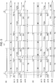
- FIG. 5 is a chart illustrating image acquisition timings of the line-of-sight detection apparatus according to the present embodiment.
- (a) to (d-4) each indicate a timing of a signal or the like as in the following.
- the timings of the trigger signals of (b-1) and (d-1) are the same.
- images are simultaneously acquired from the first camera 12 and the second camera 22.
- the light emission time of (a) or (c) and the exposure times of (b-3) and (d-3) are the same in length in the example illustrated in Fig. 5 .
- exposure E11 at the first camera 12 and exposure E12 at the second camera 22 are simultaneously performed in accordance with light emission L1 of the first light source 11.
- An image acquired by the first camera 12 that is substantially coaxial with the first light source 11 is an image for bright-pupil-image extraction
- an image acquired by the second camera 22 that is not coaxial with the first light source 11 is an image for dark-pupil-image extraction.
- the exposure E11 and the exposure E12 end simultaneously.
- data transfer D11 from the first camera 12 to the image acquisition unit 34 and data transfer D12 from the second camera 22 to the image acquisition unit 35 are individually started (the data transfer being more specifically data transfer and frame expansion).
- the length of time TG of the data transfer D11 and that of the data transfer D12 are the same for respective sections regardless of the exposure times of the light sources 11 and 21.
- exposure E21 at the first camera 12 and exposure E22 at the second camera 22 are simultaneously performed in accordance with light emission L2 of the second light source 21.
- An image acquired by the second camera 22 that is substantially coaxial with the second light source 21 is an image for bright-pupil-image extraction
- an image acquired by the first camera 12 that is not coaxial with the second light source 21 is an image for dark-pupil-image extraction.
- the exposure E21 and the exposure E22 end simultaneously.
- data transfer D21 from the first camera 12 to the image acquisition unit 34 and data transfer D22 from the second camera 22 to the image acquisition unit 35 are individually started.
- the light emission L1 and L2 as well as the exposure E11, E12, E21, and E22 so far have the same length of time that is preset.
- the image comparison unit 33 compares, in terms of brightness, the images acquired in the previous first image acquisition and the second image acquisition with each other, and sends out the comparison result to the exposure control unit 36.
- the brightness of the image for a bright pupil image and acquired in the first image acquisition is compared with the brightness of the image for a dark pupil image and acquired in the second image acquisition.
- the brightness of the image for a dark pupil image and acquired in the first image acquisition is compared with the brightness of the image for a bright pupil image and acquired in the second image acquisition.
- Fig. 5 illustrates an example in which the brightness of the image acquired in the first image acquisition based on the light emission L1 of the first light source 11 is lower than the brightness of the image acquired in the second image acquisition based on the light emission L2 of the second light source 21.
- an exposure condition is thus set higher for light emission L3 of the first light source 11 (for example, an image acquisition time (exposure) of the camera is extended) in the first image acquisition for the next period, so that the amount of light to be received is increased. Consequently an image brighter than that acquired in the previous first image acquisition is acquired in the 2nd first image acquisition based on the light emission L3 of the first light source 21.
- the exposure condition for image acquisition is corrected to be longer in the 2nd second image acquisition based on light emission L4 of the second light source 21.
- images acquired in the first image acquisition may be compared with each other in terms of brightness, and the exposure conditions may be changed for the next first image acquisition in accordance with the comparison result; and images acquired in the second image acquisition may be compared with each other in terms of brightness, and the exposure conditions may be changed for the next second image acquisition in accordance with the comparison result.
- the images (the bright pupil image and the dark pupil image) acquired in the previous first image acquisition may be compared with predetermined target values (thresholds), and an exposure state may be changed in the next first image acquisition as a result of the comparison.
- predetermined target values thresholds
- FIG. 6 (a) indicates a timing of light emission LA of the light source 11 or 21, (b) indicates a timing of exposure EA1 of the first camera 12, and (c) indicates a timing of exposure EA2 of the second camera 22.
- an image acquisition time (exposure time) EA1 of the first camera 12 differs from an image acquisition time (exposure time) EA2 of the second camera 22 in image acquisition for which light emission LA of a light source is set by considering, for example, a positional relationship between the two image receiving devices 10 and 20, the difference between light-receiving performance of the camera 12 and that of the camera 22, and the difference in brightness between an image appropriate for extracting a bright pupil image and that appropriate for extracting a dark pupil image.
- the length of the light emission LA of the light source is set to end at the end of the exposure EA21, which is the longer exposure.
- complicated control is unnecessary to acquire images for a bright pupil image and a dark pupil image.
- the detection light from the first light source 11 and the detection light from the second light source 21 have a wavelength of 850 nm; however, if the absorptance within eyeballs is almost at the same level, wavelengths other than this may also be used.
- the line-of-sight detection apparatus is useful when it is desired that line-of-sight detection be performed with high accuracy and at high speed such as in the case where the line-of-sight detection apparatus is arranged in the cabin of a vehicle and the line of sight of the driver is to be detected.
Landscapes
- Health & Medical Sciences (AREA)
- Life Sciences & Earth Sciences (AREA)
- Engineering & Computer Science (AREA)
- Physics & Mathematics (AREA)
- Medical Informatics (AREA)
- Heart & Thoracic Surgery (AREA)
- General Health & Medical Sciences (AREA)
- Animal Behavior & Ethology (AREA)
- Surgery (AREA)
- Veterinary Medicine (AREA)
- Molecular Biology (AREA)
- Biophysics (AREA)
- Public Health (AREA)
- Biomedical Technology (AREA)
- Ophthalmology & Optometry (AREA)
- Pathology (AREA)
- Human Computer Interaction (AREA)
- Theoretical Computer Science (AREA)
- General Engineering & Computer Science (AREA)
- Signal Processing (AREA)
- Dentistry (AREA)
- Psychology (AREA)
- Child & Adolescent Psychology (AREA)
- Developmental Disabilities (AREA)
- Educational Technology (AREA)
- Hospice & Palliative Care (AREA)
- Psychiatry (AREA)
- Oral & Maxillofacial Surgery (AREA)
- Social Psychology (AREA)
- Physiology (AREA)
- General Physics & Mathematics (AREA)
- Eye Examination Apparatus (AREA)
- Position Input By Displaying (AREA)
- Image Analysis (AREA)
Abstract
Description
- The present invention relates to a line-of-sight detection apparatus capable of detecting the direction of the line of sight of a car driver or other subjects.
- In a point-of-gaze detection method described in
PTL 1, using two or more cameras and light sources provided on the outside of apertures of these cameras, an image of the face of a subject is generated as a bright pupil image and a dark pupil image; for each camera, a vector from a corneal reflection point of the subject to a pupil thereof on a plane perpendicular to a reference line connecting the camera and the pupil is calculated on the basis of these images; and the direction of a line of sight of the subject with respect to the reference line of the camera is calculated using a predetermined function in accordance with this vector. The point of gaze of the subject can be detected on a predetermined plane by further correcting the function such that the calculated directions of the lines of sight corresponding to the respective cameras become close to each other and by determining the point of an intersection of the lines of sight on the predetermined plane through calculation of the directions of the lines of sight using the corrected function. - In the point-of-gaze detection method described in
PTL 1, light emission elements that output light of wavelengths different from each other are provided as the light sources. By causing these light emission elements to alternately emit light, a bright pupil image is generated when an eye of the subject is irradiated with illumination light by one of the light emission elements, and a dark pupil image is generated when the eye of the subject is irradiated with illumination light by the other light emission element. - PTL 1:
WO 2012/020760 - However, in the point-of-gaze detection method described in
PTL 1, illumination-light irradiation needs to be performed twice to generate a bright pupil image and a dark pupil image; thus, it takes time to acquire a pupil image, which makes it difficult to increase the speed of point-of-gaze or line-of-sight detection processing performed using these pupil images. - The purpose of the present invention is to provide a line-of-sight detection apparatus that can acquire, by performing detection-light irradiation once, images for generation of a bright pupil image and a dark pupil image and that can realize a higher-speed line-of-sight detection process.
- In order to solve the above-described problems, a line-of-sight detection apparatus having first and second cameras each for acquiring an image of a region including at least an eye, the first and second cameras being arranged so as to be spaced apart, a first light source that is arranged near the first camera, a second light source that is arranged near the second camera, and a pupil-image extraction unit for extracting a pupil image from a bright pupil image and a dark pupil image acquired by the respective cameras is characterized in that
first image acquisition for causing the first light source to be turned on and for acquiring a bright pupil image using the first camera and a dark pupil image using the second camera and second image acquisition for causing the second light source to be turned on and for acquiring a bright pupil image using the second camera and a dark pupil image using the first camera are performed. - The line-of-sight detection apparatus according to the present invention may include a corneal-reflection-light center detection unit for detecting corneal reflection light from the dark pupil image and a line-of-sight direction calculation unit for calculating a line-of-sight direction of the subject from the pupil image and the corneal reflection light.
- The line-of-sight detection apparatus according to the present invention can acquire a bright pupil image and a dark pupil image when one of the first light source and the second light source emits light, and can perform a line-of-sight detection process at high speed.
- Preferably, in the line-of-sight detection apparatus according to the present invention, the first camera and the second camera simultaneously acquire images when the first light source stays on, and the first camera and the second camera simultaneously acquire images when the second light source stays on.
- The cycle of acquisition of bright and dark pupil images using two cameras can be shortened by simultaneously performing image acquisition for extracting a bright pupil image and image acquisition for extracting a dark pupil image, and the line-of-sight detection process can be performed at higher speed.
- Note that, in the present invention, while the first light source stays on, image acquisition using the first camera and image acquisition using the second camera may be alternately performed such that they do not overlap. While the second light source stays on, the image acquisition using the first camera and the image acquisition using the second camera may also be alternately performed such that they do not overlap.
- According to the present invention, preferably, the first image acquisition and the second image acquisition are alternately performed.
- In this case, preferably, an exposure control unit for monitoring the brightness of the images acquired in the first image acquisition and for controlling, on the basis of the monitoring result, an exposure condition or conditions for acquiring images using the cameras in the next first image acquisition is provided.
- In addition, preferably, an exposure control unit for monitoring the brightness of the images acquired in the second image acquisition and for controlling, on the basis of the monitoring result, an exposure condition or conditions for acquiring images using the cameras in the next second image acquisition is provided.
- For example, the present invention is provided with an image comparison unit for comparing the brightness of the images acquired in the first image acquisition with the brightness of the images acquired in the second image acquisition, and the exposure control unit for controlling, in accordance with a result of the comparison made by the image comparison unit, the exposure condition or conditions in at least one of the first image acquisition and the second image acquisition.
- In this case, the image comparison unit compares the brightness of the image that is acquired in the first image acquisition and that is to be the bright pupil image with the brightness of the image that is acquired in the second image acquisition and that is to be the dark pupil image.
- In addition, the image comparison unit compares the brightness of the image that is acquired in the first image acquisition and that is to be the dark pupil image with the brightness of the image that is acquired in the second image acquisition and that is to be the bright pupil image.
- Alternatively, the image comparison unit compares the images acquired in the first image acquisition or the second image acquisition with target values.
- Variations in the brightness of acquired images due to the differences in brightness or the like between the plurality of light sources can be reduced in the above-described invention. Bright and dark pupil images whose image quality is at a certain level can thus be obtained, thereby enabling high-accuracy line-of-sight detection.
- In the line-of-sight detection apparatus according to the present invention, preferably, the exposure condition or conditions are at least one of light emission times and light emission levels of the light sources as well as image acquisition times and gains of the cameras.
- In the line-of-sight detection apparatus according to the present invention, preferably, the exposure condition or conditions include image acquisition times of the cameras, and the light emission time of the light source is controlled in accordance with the longer one of the image acquisition time of the first camera and the image acquisition time of the second camera in at least one of the first image acquisition and the second image acquisition.
- As a result, complicated control is unnecessary to acquire images for bright pupil images and dark pupil images.
- According to the present invention, images for generation of a bright pupil image and a dark pupil can be acquired while one of the first light source and the second light source stays on, and thus a higher-speed line-of-sight detection process can be realized.
- In addition, according to the present invention, variations in the brightness of acquired images due to the differences in brightness or the like between the light sources can be reduced. Bright and dark pupil images whose image quality is at a certain level can thus be obtained, thereby enabling high-accuracy line-of-sight detection. Brief Description of Drawings
- [
Fig. 1] Fig. 1 is a front view illustrating the configuration of a line-of-sight detection apparatus according to an embodiment of the present invention. - [
Fig. 2] Fig. 2 is a block diagram illustrating the configuration of the line-of-sight detection apparatus according to the embodiment of the present invention. - [
Fig. 3] Fig. 3 includes plan views illustrating relationships between line-of-sight directions of an eye of a person and cameras. - [
Fig. 4] Fig. 4 includes diagrams for describing calculation of a line-of-sight direction from the center of a pupil and the center of corneal reflection light. - [
Fig. 5] Fig. 5 is a chart illustrating image acquisition timings in the line-of-sight detection apparatus according to the embodiment of the present invention. - [
Fig. 6] Fig. 6 is a chart illustrating a timing of light emission of a light source and image acquisition timings of cameras. - In the following, a line-of-sight detection apparatus according to an embodiment of the present invention will be described in detail with reference to the drawings.
-
Fig. 1 is a front view illustrating the configuration of the line-of-sight detection apparatus according to the embodiment of the present invention.Fig. 2 is a block diagram illustrating the configuration of the line-of-sight detection apparatus according to the embodiment of the present invention.Fig. 3 includes plan views illustrating relationships between line-of-sight directions of an eye of a person and cameras.Fig. 4 includes diagrams for describing calculation of a line-of-sight direction from the center of a pupil and the center of corneal reflection light. - The line-of-sight detection apparatus according to the present embodiment is provided with, as illustrated in
Fig. 2 , twoimage receiving devices - As illustrated in
Fig. 1 andFig. 3 , the twoimage receiving devices cameras receiving devices eye 50 of the driver or the like. Thecameras - As illustrated in
Fig. 1 andFig. 2 , theimage receiving device 10 is provided with afirst light source 11 and afirst camera 12, and thefirst light source 11 is constituted by 12 light-emitting diode (LED)light sources 111. TheseLED light sources 111 are arranged in a circular shape on the outer side of alens 12L of thecamera 12 such thatoptical axes 111C thereof are spaced apart from anoptical axis 12C of thecamera 12 by a distance L11. Theimage receiving device 20 is provided with asecond light source 21 and asecond camera 22, and thesecond light source 21 is constituted by 12LED light sources 211. TheseLED light sources 211 are arranged in a circular shape on the outer side of alens 22L of thesecond camera 22 such thatoptical axes 211C thereof are spaced apart from anoptical axis 22C of thesecond camera 22 by a distance L21. - Preferably, band-pass filters corresponding to the wavelength of detection light emitted by the
light sources first camera 12 and thesecond camera 22. As a result, the extent of entry of light having wavelengths other than that of the detection light can be reduced, and thus image brightness comparison in animage comparison unit 33, pupil image extraction in a pupil-image extraction unit 40, line-of-sight direction calculation in a line-of-sightdirection calculation unit 45 can be performed with high accuracy. - The
LED light sources 111 of thefirst light source 11 and theLED light sources 211 of thesecond light source 21 emit, for example, infrared light (near-infrared light) having a wavelength of 850 nm as the detection light, and are arranged so that this detection light can be supplied to the eyes of the subject. Here, 850 nm is a wavelength at which the optical absorptance is low within the eyeballs of the eyes of a person, and light of this wavelength tends to be reflected by the retinas at the back of the eyeballs. - In view of the distance between the line-of-sight detection apparatus and the driver as the subject, the distance L11 between the optical axis of the
first camera 12 and each of the optical axes of theLED light sources 111 is sufficiently shorter than the distance L10 between the optical axis of thefirst camera 12 and the optical axis of thesecond camera 22, and thus the optical axes of thefirst light source 11 and thefirst camera 12 can be regarded as axes that are substantially coaxial with each other. Likewise, the distance L21 between the optical axis of thesecond camera 22 and each of the optical axes of theLED light sources 211 is sufficiently shorter than the distance L10 between the optical axis of thefirst camera 12 and the optical axis of thesecond camera 22, and thus the optical axes of thesecond light source 21 and thesecond camera 22 can be regarded as axes that are substantially coaxial with each other. Note that the distance L10 between the optical axes is set to, for example, a length that almost matches the distance between both eyes of a person. - In contrast to this, since the distance L10 between the optical axis of the
first camera 12 and the optical axis of thesecond camera 22 is sufficiently long, the optical axes of thefirst light source 11 and thefirst camera 12 are not coaxial with the optical axes of the secondlight source 21 and thesecond camera 22. Regarding the above-described state, expressions such as "two members are substantially coaxial" or the like may be used, and expressions such as "two members are not coaxial" or the like may be used in the following description. - The computation control unit CC includes a CPU and a memory of a computer, and computation for functions of the blocks illustrated in
Fig. 2 is performed by executing preinstalled software. - The computation control unit CC illustrated in
Fig. 2 is provided with light-source control units image comparison unit 33,image acquisition units exposure control unit 36, the pupil-image extraction unit 40, a pupilcenter calculation unit 43, a corneal-reflection-lightcenter detection unit 44, and the line-of-sightdirection calculation unit 45. - The light-
source control unit 31 and the light-source control unit 32 control on-off of thefirst light source 11 and that of the secondlight source 21, respectively, in accordance with a command signal from theexposure control unit 36. Images acquired by thecameras image acquisition units - Regarding the images acquired by the
image acquisition units image comparison unit 33 compares the brightness of images acquired in first image acquisition and the brightness of images acquired in second image acquisition with each other. - Here, the first image acquisition means a process where images are individually acquired from the
first camera 12 and thesecond camera 22 at the same time or at almost the same time when the detection light is supplied from thefirst light source 11, and the second image acquisition means a process where images are individually acquired from thefirst camera 12 and thesecond camera 22 at the same time or at almost the same time when the detection light is supplied from the secondlight source 21. Note that the case where the detection light is supplied from the second light source may be first image acquisition, and the case where the detection light is supplied from the first light source may be second image acquisition. - In the
image comparison unit 36, an image acquired to obtain a bright pupil image by thefirst camera 12 in the first image acquisition is compared with, in terms of brightness, an image acquired to obtain a dark pupil image by thefirst camera 12 in the second image acquisition. In addition, an image acquired to obtain a dark pupil image by thesecond camera 22 in the first image acquisition is compared with, in terms of brightness, an image acquired to obtain a bright pupil image by thesecond camera 22 in the second image acquisition. By supplying this comparison result to theexposure control unit 36, the difference in brightness between the bright and dark pupil images acquired by the first camera 12 (the difference in brightness between images of the face excluding pupil portions) can be eliminated or reduced, and the difference in brightness between the dark and bright pupil images acquired by the second camera 22 (the difference in brightness between images of the face excluding pupil portions) can be eliminated or reduced in the first image acquisition and the second image acquisition. - In addition, as an operation of the
image comparison unit 36 in another embodiment, an image acquired to obtain a bright pupil image by thefirst camera 12 in the first image acquisition may be compared with, in terms of brightness, an image acquired to obtain a bright pupil image by thefirst camera 12 in the next first image acquisition, and an image acquired to obtain a dark pupil image by thesecond camera 12 in the first image acquisition may also be compared with, in terms of brightness, an image acquired to obtain a dark pupil image by thesecond camera 12 in the next first image acquisition. - Likewise, images for obtaining bright pupil images may be compared with each other in terms of brightness in the second image acquisition and in the next second image acquisition, and images for obtaining dark pupil images may be compared with each other in terms of brightness in the second image acquisition and in the next second image acquisition. By supplying this comparison result to the
exposure control unit 36, bright pupil images and dark pupil images that are not varied in terms of brightness can be obtained in the first image acquisition and in the second image acquisition. - Alternatively, image brightness references may have been determined as target values in advance. In the first image acquisition in the
image comparison unit 33, the brightness of an image acquired to obtain a bright pupil image by thefirst camera 12 is compared with a target value for bright pupil images, and the brightness of an image acquired to obtain a dark pupil image by thesecond camera 22 is compared with a target value for dark pupil images. The comparison result may also be supplied to theexposure control unit 36. Under this control, exposure conditions for the next first image acquisition are changed so as to optimize the brightness of the image in the previous first image acquisition. The same applies to the second image acquisition. - A comparison between images in terms of brightness or a comparison between the brightness of an image and a target value is, for example, a comparison between the averages of brightness values of the entire images acquired by the
image acquisition units - The
exposure control unit 36 controls, in accordance with the result of the comparison made by theimage comparison unit 33, exposure conditions for capturing images such that the difference in brightness between images to be compared and acquired in the first image acquisition and the second image acquisition falls within a predetermined range. - Regarding the exposure conditions controlled by the
exposure control unit 36, for example, at least one of a light emission time and a light emission level of thefirst light source 11, a light emission time and a light emission level of the secondlight source 21, an image acquisition time (a camera exposure time) and a sensor gain of thefirst camera 12, and an image acquisition time (a camera exposure time) and a sensor gain of thesecond camera 22 is controlled. A signal corresponding to this control is output from theexposure control unit 36 to the light-source control units first camera 12, and thesecond camera 22. The light emission times and light emission levels of thefirst light source 11 and the secondlight source 21 are set in accordance with the control signal in the light-source control units first camera 12 and thesecond camera 22. - The images acquired by the
image acquisition units image extraction unit 40 on a per-frame basis. The pupil-image extraction unit 40 is provided with a bright-pupil-image detection unit 41 and a dark-pupil-image detection unit 42. -
Fig. 3 includes plan views schematically illustrating relationships between the line-of-sight directions of theeye 50 of the subject and the cameras.Fig. 4 includes diagrams for describing calculation of a line-of-sight direction from the center of a pupil and the center of corneal reflection light. InFig. 3(A) and Fig. 4(A) , a line-of-sight direction VL of the subject is directed toward the midpoint between theimage receiving device 10 and theimage receiving device 20. InFig. 3(B) and Fig. 4(B) , the line-of-sight direction VL is directed in the direction of the optical axis 13C of the camera. - The
eye 50 has acornea 51 at the front, and apupil 52 and acrystalline lens 53 are positioned behind thecornea 51. Aretina 54 is present at the rearmost portion. - Infrared light of 850 nm wavelength emitted from the
first light source 11 and the secondlight source 21 has low absorptance within the eyeball, and the light tends to be reflected by theretina 54. Thus, when thefirst light source 11 is turned on, infrared light reflected by theretina 54 is detected through thepupil 52, and thepupil 52 appears bright in an image acquired by thefirst camera 12 that is substantially coaxial with thefirst light source 11. This image is extracted as a bright pupil image by the bright-pupil-image detection unit 41. The same applies to an image acquired by thesecond camera 22 that is substantially coaxial with the secondlight source 21 when this is turned on. - In contrast to this, in the case where an image is acquired by the
second camera 22 that is not coaxial with thefirst light source 11 when thefirst light source 11 is turned on, infrared light reflected by theretina 54 tends not to be detected by thesecond camera 22 and thus thepupil 52 appears dark. This image is thus extracted as a dark pupil image by the dark-pupil-image detection unit 42. The same applies to an image acquired by thefirst camera 12 that is not coaxial with the secondlight source 21 when this is turned on. - In the pupil-
image extraction unit 40 illustrated inFig. 2 , the dark pupil image detected by the dark-pupil-image detection unit 42 is subtracted from the bright pupil image detected by the bright-pupil-image detection unit 41, and preferably the images except for thepupil 52 are canceled out and a pupil image signal with which the shape of thepupil 52 appears bright is generated. This pupil image signal is supplied to the pupilcenter calculation unit 43. The pupil image signal is subjected to image processing and binarized, and an area image that is a portion corresponding to the shape and area of thepupil 52 is calculated in the pupilcenter calculation unit 43. Furthermore, an ellipse including this area image is extracted, and the point of intersection of the major and minor axes of the ellipse is calculated as the center position of thepupil 52. Alternatively, the center of thepupil 52 is determined from a pupil-image brightness distribution. - In addition, a dark pupil image signal detected by the dark-pupil-
image detection unit 42 is supplied to the corneal-reflection-lightcenter detection unit 44. The dark pupil image signal includes a brightness signal based on reflection light that has been reflected from areflection point 55 of thecornea 51 illustrated inFig. 3 and Fig. 4 . - As illustrated in
Fig. 3(A) , when either of the light sources stays on, light from the light source is reflected by the surface of thecornea 51, and the light is acquired by both of thefirst camera 12 and thesecond camera 22 and is detected by the bright-pupil-image detection unit 41 and the dark-pupil-image detection unit 42. In particular, in the dark-pupil-image detection unit 42, an image of thepupil 52 is relatively dark and thus the reflection light that has been reflected from thereflection point 55 of thecornea 51 is bright and detected as a spot image. - The reflection light from the
reflection point 55 of thecornea 51 forms a Purkinje image, and a spot image having a significantly small area is acquired by image pickup elements of thecameras Fig. 4 . In the corneal-reflection-lightcenter detection unit 44, the spot image is subjected to image processing, and the center of the reflection light from thereflection point 55 of thecornea 51 is determined. - A pupil center calculation value calculated by the pupil
center calculation unit 43 and a corneal-reflection-light center calculation value calculated by the corneal-reflection-lightcenter detection unit 44 are supplied to the line-of-sightdirection calculation unit 45. A line-of-sight direction is detected from the pupil center calculation value and the corneal-reflection-light center calculation value in the line-of-sightdirection calculation unit 45. - In the case illustrated in
Fig. 3(A) , the line-of-sight direction VL of theeye 50 of the person is directed toward the midpoint between the twoimage receiving devices reflection point 55 from thecornea 51 matches the center of thepupil 52 as illustrated inFig. 4(A) . In contrast to this, in the case illustrated inFig. 3(B) , the line-of-sight direction VL of theeye 50 of the person is directed slightly leftward, and thus the center of thepupil 52 and the center of thereflection point 55 from thecornea 51 become misaligned as illustrated inFig. 4(B) . - In the line-of-sight
direction calculation unit 45, a direct distance α between the center of thepupil 52 and the center of thereflection point 55 from thecornea 51 is calculated (Fig. 4(B) ). In addition, an X-Y coordinate system is set using the center of thepupil 52 as the origin, and a tilt angle β between a line connecting the center of thepupil 52 with the center of thereflection point 55 and the X axis is calculated. Furthermore, the line-of-sight direction VL is calculated from the direct distance α and the tilt angle β. - The above-described pupil image extraction, corneal-reflection-light center detection, and calculation of the line-of-sight direction VL, the calculation being performed using the pupil image extraction and corneal-reflection-light center detection, are performed on the basis of stereo images obtained by the two
cameras - In the line-of-sight detection apparatus, the
first light source 11 is caused to emit light in the first image acquisition, and images are captured by thefirst camera 12 and thesecond camera 22 at the same time or almost at the same time during the light emission. The second light source is caused to emit light in the second image acquisition, and images are captured by thefirst camera 12 and thesecond camera 22 at the same time or almost at the same time during the light emission. - Relationships among the first image acquisition and the second image acquisition as well as bright pupil image detection and dark pupil image detection are as follows.
- (A) First image acquisition: the
first light source 11 is turned on,- (A-1) The
first camera 12 performs image acquisition to obtain a bright pupil image. - (A-2) The
second camera 22 performs image acquisition to obtain a dark pupil image.
- (A-1) The
- (B) Second image acquisition: the second
light source 12 is turned on,- (B-1) The
second camera 22 performs image acquisition to obtain a bright pupil image. - (B-2) The
first camera 12 performs image acquisition to obtain a dark pupil image.
- (B-1) The
- The above-described (A) first image acquisition and (B) second image acquisition are basically alternately performed.
- After performing the first image acquisition once and the second image acquisition once, every time image acquisition is performed, the
image comparison unit 33 compares, in terms of brightness, the images acquired in the previous first image acquisition and second image acquisition with each other, and sends out the comparison result to theexposure control unit 36. Theexposure control unit 36 having received the comparison result generates, in accordance with the comparison result, a control signal for controlling the exposure conditions of a certain light source such that the brightness of images to be acquired in future image acquisition falls within a predetermined range. This control signal is sent out to the light-source control unit image acquisition units - In addition, in this embodiment, the first camera acquires a bright pupil image and the second camera acquires a dark pupil image in the first image acquisition. At this point in time, a pupil image is obtained from the bright pupil image and the dark pupil image, and furthermore corneal reflection light is obtained and a line-of-sight direction can be calculated. Likewise, since the first camera acquires a dark pupil image and the second camera acquires a bright pupil image in the second image acquisition, a line-of-sight direction can also be calculated from a pupil image and corneal reflection light at this point in time.
- In this manner, the line-of-sight direction can be calculated at both the time of first image acquisition and the time of second image acquisition, and thus the speed of a line-of-sight detection operation can be increased.
- In the following, a more specific description will be given with reference to
Fig. 5. Fig. 5 is a chart illustrating image acquisition timings of the line-of-sight detection apparatus according to the present embodiment. InFig. 5 , (a) to (d-4) each indicate a timing of a signal or the like as in the following. - (a): Light emission timings of the
first light source 11 - (b-1): A trigger signal (TE1, TE2, TE3, TE4, TE5, and so on) for commanding the
first camera 12 to start exposure - (b-2): A trigger signal (TD1, TD2, TD3, TD4, TD5, and so on) for commanding starting of image acquisition from the
first camera 12 to theimage acquisition unit 34 - (b-3): Image acquisition (exposure) at the
first camera 12 - (b-4): Data transfer from the
first camera 12 to theimage acquisition unit 34 - (c): Light emission timings of the second
light source 21 - (d-1): A trigger signal for commanding the
second camera 22 to start exposure - (d-2): A trigger signal for commanding starting of image acquisition from the
second camera 22 to theimage acquisition unit 35 - (d-3): Image acquisition (exposure) at the
second camera 22 - (d-4): Data transfer from the
second camera 22 to theimage acquisition unit 35 - Here, the timings of the trigger signals of (b-1) and (d-1) are the same. As a result, images are simultaneously acquired from the
first camera 12 and thesecond camera 22. In addition, in units of image acquisition, the light emission time of (a) or (c) and the exposure times of (b-3) and (d-3) are the same in length in the example illustrated inFig. 5 . - In the example illustrated in
Fig. 5 , as the first image acquisition, exposure E11 at thefirst camera 12 and exposure E12 at thesecond camera 22 are simultaneously performed in accordance with light emission L1 of thefirst light source 11. An image acquired by thefirst camera 12 that is substantially coaxial with thefirst light source 11 is an image for bright-pupil-image extraction, and an image acquired by thesecond camera 22 that is not coaxial with thefirst light source 11 is an image for dark-pupil-image extraction. - When the light emission L1 ends, the exposure E11 and the exposure E12 end simultaneously. Upon completion of the exposure, data transfer D11 from the
first camera 12 to theimage acquisition unit 34 and data transfer D12 from thesecond camera 22 to theimage acquisition unit 35 are individually started (the data transfer being more specifically data transfer and frame expansion). The length of time TG of the data transfer D11 and that of the data transfer D12 are the same for respective sections regardless of the exposure times of thelight sources - Next, as the second image acquisition, exposure E21 at the
first camera 12 and exposure E22 at thesecond camera 22 are simultaneously performed in accordance with light emission L2 of the secondlight source 21. An image acquired by thesecond camera 22 that is substantially coaxial with the secondlight source 21 is an image for bright-pupil-image extraction, and an image acquired by thefirst camera 12 that is not coaxial with the secondlight source 21 is an image for dark-pupil-image extraction. When the light emission L2 ends, the exposure E21 and the exposure E22 end simultaneously. Upon completion of the exposure, data transfer D21 from thefirst camera 12 to theimage acquisition unit 34 and data transfer D22 from thesecond camera 22 to theimage acquisition unit 35 are individually started. The light emission L1 and L2 as well as the exposure E11, E12, E21, and E22 so far have the same length of time that is preset. - Here, the
image comparison unit 33 compares, in terms of brightness, the images acquired in the previous first image acquisition and the second image acquisition with each other, and sends out the comparison result to theexposure control unit 36. In this comparison, the brightness of the image for a bright pupil image and acquired in the first image acquisition is compared with the brightness of the image for a dark pupil image and acquired in the second image acquisition. In addition, the brightness of the image for a dark pupil image and acquired in the first image acquisition is compared with the brightness of the image for a bright pupil image and acquired in the second image acquisition. -
Fig. 5 illustrates an example in which the brightness of the image acquired in the first image acquisition based on the light emission L1 of thefirst light source 11 is lower than the brightness of the image acquired in the second image acquisition based on the light emission L2 of the secondlight source 21. In theexposure control unit 36, an exposure condition is thus set higher for light emission L3 of the first light source 11 (for example, an image acquisition time (exposure) of the camera is extended) in the first image acquisition for the next period, so that the amount of light to be received is increased. Consequently an image brighter than that acquired in the previous first image acquisition is acquired in the 2nd first image acquisition based on the light emission L3 of thefirst light source 21. - Furthermore, in the example illustrated in
Fig. 5 , as a result of comparing the second image acquisition based on the light emission L2 of the secondlight source 21 with the 2nd first image acquisition based on the light emission L3 of thefirst light source 11, the exposure condition for image acquisition is corrected to be longer in the 2nd second image acquisition based on light emission L4 of the secondlight source 21. - Note that, as described above, images acquired in the first image acquisition may be compared with each other in terms of brightness, and the exposure conditions may be changed for the next first image acquisition in accordance with the comparison result; and images acquired in the second image acquisition may be compared with each other in terms of brightness, and the exposure conditions may be changed for the next second image acquisition in accordance with the comparison result.
- Alternatively, the images (the bright pupil image and the dark pupil image) acquired in the previous first image acquisition may be compared with predetermined target values (thresholds), and an exposure state may be changed in the next first image acquisition as a result of the comparison. The same applies to the second image acquisition.
- Next, in
Fig. 6 , (a) indicates a timing of light emission LA of thelight source first camera 12, and (c) indicates a timing of exposure EA2 of thesecond camera 22. - In the example illustrated in
Fig. 6 , an image acquisition time (exposure time) EA1 of thefirst camera 12 differs from an image acquisition time (exposure time) EA2 of thesecond camera 22 in image acquisition for which light emission LA of a light source is set by considering, for example, a positional relationship between the twoimage receiving devices camera 12 and that of thecamera 22, and the difference in brightness between an image appropriate for extracting a bright pupil image and that appropriate for extracting a dark pupil image. - In this case, the length of the light emission LA of the light source is set to end at the end of the exposure EA21, which is the longer exposure. As a result, complicated control is unnecessary to acquire images for a bright pupil image and a dark pupil image.
- In addition, in the above-described embodiment, the detection light from the
first light source 11 and the detection light from the secondlight source 21 have a wavelength of 850 nm; however, if the absorptance within eyeballs is almost at the same level, wavelengths other than this may also be used. - With the configuration above, the following advantages are obtained according to the above-described embodiment.
- (1) When, as the first image acquisition or the second image acquisition, detection light is supplied from one of the
first light source 11 and the secondlight source 21, a line-of-sight detection process can be performed at high speed by acquiring an image for extracting a bright pupil image using a camera that is substantially coaxial with the light source and by acquiring an image for extracting a dark pupil image using a camera that is not coaxial with the light source. In addition, the cycle of emission of detection light from the plurality of light sources can be shortened by simultaneously performing image acquisition for extracting a bright pupil image and image acquisition for extracting a dark pupil image, and thus the line-of-sight detection process can be performed at higher speed. Line-of-sight detection can be realized with high accuracy by using a plurality of images for extracting pupil images, the plurality of images being obtained by alternately performing the first image acquisition and the second image acquisition. - (2) With an image comparison unit that compares, in terms of brightness, two images acquired in the first image acquisition with two images acquired in the second image acquisition and an exposure control unit that controls, in accordance with the result of the comparison made by the image comparison unit, exposure conditions of light sources such that the brightness of images to be acquired in the first image acquisition and the second image acquisition falls within a predetermined range, variations in the brightness of acquired images due to the differences in brightness or the like between the plurality of light sources can be reduced. Bright and dark pupil images whose image quality is at a certain level can thus be obtained, thereby enabling high-accuracy line-of-sight detection.
- The present invention has been described with reference to the embodiment above; however, the present invention is not limited to the embodiment above and can be improved or changed for improvement or within the scope of the concept of the present invention.
- As described above, the line-of-sight detection apparatus according to the present invention is useful when it is desired that line-of-sight detection be performed with high accuracy and at high speed such as in the case where the line-of-sight detection apparatus is arranged in the cabin of a vehicle and the line of sight of the driver is to be detected.
-
- 10, 20
- image receiving device
- 11
- first light source
- 12
- first camera
- 12C
- optical axis
- 21
- second light source
- 22
- second camera
- 22C
- optical axis
- 33
- image comparison unit
- 34, 35
- image acquisition unit
- 36
- exposure control unit
- 40
- pupil-image extraction unit
- 41
- bright-pupil-image detection unit
- 42
- dark-pupil-image detection unit
- 43
- pupil center calculation unit
- 44
- corneal-reflection-light center detection unit
- 45
- line-of-sight direction detection unit
- 50
- eye
Claims (12)
- A line-of-sight detection apparatus having first and second cameras each for acquiring an image of a region including at least an eye, the first and second cameras being arranged so as to be spaced apart, a first light source that is arranged near the first camera, a second light source that is arranged near the second camera, and a pupil-image extraction unit for extracting a pupil image from a bright pupil image and a dark pupil image acquired by the respective cameras, the line-of-sight detection apparatus characterized in that
first image acquisition for causing the first light source to be turned on and for acquiring a bright pupil image using the first camera and a dark pupil image using the second camera and second image acquisition for causing the second light source to be turned on and for acquiring a bright pupil image using the second camera and a dark pupil image using the first camera are performed. - The line-of-sight detection apparatus according to Claim 1, comprising: a corneal-reflection-light center detection unit for detecting corneal reflection light from the dark pupil image; and a line-of-sight direction calculation unit for calculating a line-of-sight direction of the subject from the pupil image and the corneal reflection light.
- The line-of-sight detection apparatus according to Claim 1 or 2, wherein the first camera and the second camera simultaneously acquire images when the first light source stays on, and the first camera and the second camera simultaneously acquire images when the second light source stays on.
- The line-of-sight detection apparatus according to any one of Claims 1 to 3, wherein the first image acquisition and the second image acquisition are alternately performed.
- The line-of-sight detection apparatus according to any one of Claims 1 to 4, provided with an exposure control unit for monitoring the brightness of the images acquired in the first image acquisition and for controlling, on the basis of the monitoring result, an exposure condition or conditions for acquiring images using the cameras in the next first image acquisition.
- The line-of-sight detection apparatus according to any one of Claims 1 to 5, provided with an exposure control unit for monitoring the brightness of the images acquired in the second image acquisition and for controlling, on the basis of the monitoring result, an exposure condition or conditions for acquiring images using the cameras in the next second image acquisition.
- The line-of-sight detection apparatus according to any one of Claims 1 to 5, provided with: an image comparison unit for comparing the brightness of the images acquired in the first image acquisition with the brightness of the images acquired in the second image acquisition, and
the exposure control unit for controlling, in accordance with a result of the comparison made by the image comparison unit, the exposure condition or conditions in at least one of the first image acquisition and the second image acquisition. - The line-of-sight detection apparatus according to Claim 7, wherein the image comparison unit compares the brightness of the image that is acquired in the first image acquisition and that is to be the bright pupil image with the brightness of the image that is acquired in the second image acquisition and that is to be the dark pupil image.
- The line-of-sight detection apparatus according to Claim 7 or 8, wherein the image comparison unit compares the brightness of the image that is acquired in the first image acquisition and that is to be the dark pupil image with the brightness of the image that is acquired in the second image acquisition and that is to be the bright pupil image.
- The line-of-sight detection apparatus according to Claim 7, wherein the image comparison unit compares the images acquired in the first image acquisition or the second image acquisition with target values.
- The line-of-sight detection apparatus according to any one of Claims 5 to 10, wherein the exposure condition or conditions are at least one of light emission times and light emission levels of the light sources as well as image acquisition times and gains of the cameras.
- The line-of-sight detection apparatus according to Claim 8, wherein the exposure condition or conditions include image acquisition times of the cameras, and the light emission time of the light source is controlled in accordance with the longer one of the image acquisition time of the first camera and the image acquisition time of the second camera in at least one of the first image acquisition and the second image acquisition.
Applications Claiming Priority (2)
| Application Number | Priority Date | Filing Date | Title |
|---|---|---|---|
| JP2014176128 | 2014-08-29 | ||
| PCT/JP2015/073350 WO2016031666A1 (en) | 2014-08-29 | 2015-08-20 | Line-of-sight detection device |
Publications (2)
| Publication Number | Publication Date |
|---|---|
| EP3187100A1 true EP3187100A1 (en) | 2017-07-05 |
| EP3187100A4 EP3187100A4 (en) | 2018-05-09 |
Family
ID=55399561
Family Applications (1)
| Application Number | Title | Priority Date | Filing Date |
|---|---|---|---|
| EP15834918.3A Withdrawn EP3187100A4 (en) | 2014-08-29 | 2015-08-20 | Line-of-sight detection device |
Country Status (5)
| Country | Link |
|---|---|
| US (1) | US20170156590A1 (en) |
| EP (1) | EP3187100A4 (en) |
| JP (1) | JP6381654B2 (en) |
| CN (1) | CN106793944A (en) |
| WO (1) | WO2016031666A1 (en) |
Cited By (1)
| Publication number | Priority date | Publication date | Assignee | Title |
|---|---|---|---|---|
| WO2023046406A1 (en) * | 2021-09-23 | 2023-03-30 | Continental Automotive Technologies GmbH | An image processing system and method thereof |
Families Citing this family (6)
| Publication number | Priority date | Publication date | Assignee | Title |
|---|---|---|---|---|
| WO2017154370A1 (en) * | 2016-03-09 | 2017-09-14 | アルプス電気株式会社 | Sight line detection device and sight line detection method |
| US10726574B2 (en) * | 2017-04-11 | 2020-07-28 | Dolby Laboratories Licensing Corporation | Passive multi-wearable-devices tracking |
| JP7173836B2 (en) | 2018-11-05 | 2022-11-16 | 京セラ株式会社 | Controller, position determination device, position determination system, display system, program, and recording medium |
| GB2611157B (en) * | 2021-07-30 | 2025-01-08 | Canon Kk | Image pickup apparatus used as action camera, calibration system, control method for image pickup apparatus, and storage medium storing control program for... |
| CN114495286A (en) * | 2021-12-02 | 2022-05-13 | 北京萤视科技有限公司 | Living body detection device and method |
| SE546809C2 (en) * | 2022-06-22 | 2025-02-25 | Tobii Ab | An eye tracking system |
Family Cites Families (12)
| Publication number | Priority date | Publication date | Assignee | Title |
|---|---|---|---|---|
| JP2950759B2 (en) * | 1995-08-31 | 1999-09-20 | キヤノン株式会社 | Optical equipment having a line-of-sight detection device |
| JP4491604B2 (en) * | 2004-12-17 | 2010-06-30 | 国立大学法人静岡大学 | Pupil detection device |
| JP4824420B2 (en) * | 2006-02-07 | 2011-11-30 | アイテック株式会社 | Gaze vector detection method and apparatus |
| JP4966816B2 (en) * | 2007-10-25 | 2012-07-04 | 株式会社日立製作所 | Gaze direction measuring method and gaze direction measuring device |
| EP2238889B1 (en) * | 2009-04-01 | 2011-10-12 | Tobii Technology AB | Adaptive camera and illuminator eyetracker |
| JP5529660B2 (en) * | 2010-07-20 | 2014-06-25 | パナソニック株式会社 | Pupil detection device and pupil detection method |
| US9135708B2 (en) * | 2010-08-09 | 2015-09-15 | National University Corporation Shizuoka University | Gaze point detection method and gaze point detection device |
| US9329683B2 (en) * | 2010-12-08 | 2016-05-03 | National University Corporation Shizuoka University | Method for detecting point of gaze and device for detecting point of gaze |
| JP5998863B2 (en) * | 2012-11-09 | 2016-09-28 | 株式会社Jvcケンウッド | Gaze detection device and gaze detection method |
| WO2014181775A1 (en) * | 2013-05-08 | 2014-11-13 | 国立大学法人静岡大学 | Pupil detection light source device, pupil detection device and pupil detection method |
| AU2015235511B2 (en) * | 2014-03-25 | 2017-06-01 | Sysmex Corporation | Detection device and detection method |
| JP6201956B2 (en) * | 2014-10-24 | 2017-09-27 | 株式会社Jvcケンウッド | Gaze detection device and gaze detection method |
-
2015
- 2015-08-20 EP EP15834918.3A patent/EP3187100A4/en not_active Withdrawn
- 2015-08-20 WO PCT/JP2015/073350 patent/WO2016031666A1/en not_active Ceased
- 2015-08-20 CN CN201580046029.6A patent/CN106793944A/en active Pending
- 2015-08-20 JP JP2016545466A patent/JP6381654B2/en not_active Expired - Fee Related
-
2017
- 2017-02-17 US US15/436,165 patent/US20170156590A1/en not_active Abandoned
Cited By (2)
| Publication number | Priority date | Publication date | Assignee | Title |
|---|---|---|---|---|
| WO2023046406A1 (en) * | 2021-09-23 | 2023-03-30 | Continental Automotive Technologies GmbH | An image processing system and method thereof |
| GB2611289A (en) * | 2021-09-23 | 2023-04-05 | Continental Automotive Tech Gmbh | An image processing system and method thereof |
Also Published As
| Publication number | Publication date |
|---|---|
| JP6381654B2 (en) | 2018-08-29 |
| EP3187100A4 (en) | 2018-05-09 |
| WO2016031666A1 (en) | 2016-03-03 |
| US20170156590A1 (en) | 2017-06-08 |
| CN106793944A (en) | 2017-05-31 |
| JPWO2016031666A1 (en) | 2017-06-22 |
Similar Documents
| Publication | Publication Date | Title |
|---|---|---|
| JP6381654B2 (en) | Gaze detection device | |
| JP5145555B2 (en) | Pupil detection method | |
| CN108027977B (en) | Sight line detection device and sight line detection method | |
| US9152850B2 (en) | Authentication apparatus, authentication method, and program | |
| JP4853389B2 (en) | Face image capturing device | |
| EP2649932A1 (en) | Method for detecting point of gaze and device for detecting point of gaze | |
| US20160063304A1 (en) | Line-of-sight detection apparatus | |
| CN108140244B (en) | Line-of-sight detection device and line-of-sight detection method | |
| CN110532849B (en) | Multispectral image processing system for face detection | |
| EP2995241B1 (en) | Pupil detection light source device, pupil detection device and pupil detection method | |
| US20160063334A1 (en) | In-vehicle imaging device | |
| JP2016085588A (en) | Gaze detection device and gaze detection method | |
| JP2016028669A (en) | Pupil detection device and pupil detection method | |
| US11179035B2 (en) | Real-time removal of IR LED reflections from an image | |
| US10223779B2 (en) | Superimposed image creation apparatus and superimposed image creation method | |
| JP6900994B2 (en) | Line-of-sight detection device and line-of-sight detection method | |
| JP6289439B2 (en) | Image processing device | |
| JP2016051312A (en) | Visual line detection device | |
| JP2019033971A (en) | Endoscope device | |
| JP2018190213A (en) | Face recognition device and sight line detection device | |
| JP2017124037A (en) | Visual line detection device | |
| WO2023053556A1 (en) | Information processing device, information processing method, and program | |
| JP6693149B2 (en) | Pupil detection device and pupil detection method | |
| JP7621639B2 (en) | Pupil detection device and pupil detection method | |
| WO2017134918A1 (en) | Line-of-sight detection device |
Legal Events
| Date | Code | Title | Description |
|---|---|---|---|
| PUAI | Public reference made under article 153(3) epc to a published international application that has entered the european phase |
Free format text: ORIGINAL CODE: 0009012 |
|
| 17P | Request for examination filed |
Effective date: 20170222 |
|
| AK | Designated contracting states |
Kind code of ref document: A1 Designated state(s): AL AT BE BG CH CY CZ DE DK EE ES FI FR GB GR HR HU IE IS IT LI LT LU LV MC MK MT NL NO PL PT RO RS SE SI SK SM TR |
|
| AX | Request for extension of the european patent |
Extension state: BA ME |
|
| DAV | Request for validation of the european patent (deleted) | ||
| DAX | Request for extension of the european patent (deleted) | ||
| RIC1 | Information provided on ipc code assigned before grant |
Ipc: A61B 3/113 20060101AFI20180329BHEP |
|
| A4 | Supplementary search report drawn up and despatched |
Effective date: 20180410 |
|
| STAA | Information on the status of an ep patent application or granted ep patent |
Free format text: STATUS: THE APPLICATION HAS BEEN WITHDRAWN |
|
| 18W | Application withdrawn |
Effective date: 20181030 |