EP3187088A1 - Cleaning sheet and cleaning instrument package - Google Patents
Cleaning sheet and cleaning instrument package Download PDFInfo
- Publication number
- EP3187088A1 EP3187088A1 EP15829570.9A EP15829570A EP3187088A1 EP 3187088 A1 EP3187088 A1 EP 3187088A1 EP 15829570 A EP15829570 A EP 15829570A EP 3187088 A1 EP3187088 A1 EP 3187088A1
- Authority
- EP
- European Patent Office
- Prior art keywords
- receiving
- region
- opening
- holder
- bonded
- Prior art date
- Legal status (The legal status is an assumption and is not a legal conclusion. Google has not performed a legal analysis and makes no representation as to the accuracy of the status listed.)
- Withdrawn
Links
Images








Classifications
-
- A—HUMAN NECESSITIES
- A47—FURNITURE; DOMESTIC ARTICLES OR APPLIANCES; COFFEE MILLS; SPICE MILLS; SUCTION CLEANERS IN GENERAL
- A47L—DOMESTIC WASHING OR CLEANING; SUCTION CLEANERS IN GENERAL
- A47L13/00—Implements for cleaning floors, carpets, furniture, walls, or wall coverings
- A47L13/10—Scrubbing; Scouring; Cleaning; Polishing
- A47L13/38—Other dusting implements
-
- A—HUMAN NECESSITIES
- A47—FURNITURE; DOMESTIC ARTICLES OR APPLIANCES; COFFEE MILLS; SPICE MILLS; SUCTION CLEANERS IN GENERAL
- A47L—DOMESTIC WASHING OR CLEANING; SUCTION CLEANERS IN GENERAL
- A47L13/00—Implements for cleaning floors, carpets, furniture, walls, or wall coverings
- A47L13/10—Scrubbing; Scouring; Cleaning; Polishing
- A47L13/16—Cloths; Pads; Sponges
-
- A—HUMAN NECESSITIES
- A47—FURNITURE; DOMESTIC ARTICLES OR APPLIANCES; COFFEE MILLS; SPICE MILLS; SUCTION CLEANERS IN GENERAL
- A47L—DOMESTIC WASHING OR CLEANING; SUCTION CLEANERS IN GENERAL
- A47L13/00—Implements for cleaning floors, carpets, furniture, walls, or wall coverings
- A47L13/10—Scrubbing; Scouring; Cleaning; Polishing
- A47L13/20—Mops
-
- A—HUMAN NECESSITIES
- A47—FURNITURE; DOMESTIC ARTICLES OR APPLIANCES; COFFEE MILLS; SPICE MILLS; SUCTION CLEANERS IN GENERAL
- A47L—DOMESTIC WASHING OR CLEANING; SUCTION CLEANERS IN GENERAL
- A47L13/00—Implements for cleaning floors, carpets, furniture, walls, or wall coverings
- A47L13/10—Scrubbing; Scouring; Cleaning; Polishing
- A47L13/20—Mops
- A47L13/24—Frames for mops; Mop heads
- A47L13/254—Plate frames
- A47L13/256—Plate frames for mops made of cloth
-
- A—HUMAN NECESSITIES
- A47—FURNITURE; DOMESTIC ARTICLES OR APPLIANCES; COFFEE MILLS; SPICE MILLS; SUCTION CLEANERS IN GENERAL
- A47L—DOMESTIC WASHING OR CLEANING; SUCTION CLEANERS IN GENERAL
- A47L13/00—Implements for cleaning floors, carpets, furniture, walls, or wall coverings
- A47L13/10—Scrubbing; Scouring; Cleaning; Polishing
Definitions
- the present invention relates to a cleaning sheet and a cleaning tool package for cleaning an object to be cleaned.
- JP-A Japanese Unexamined Patent Application Publication ( JP-A) No. 2008-253286 discloses a cleaning tool having a cleaning element and a cleaning element holder. This publication is centered on a technique for providing the cleaning tool having a single cleaning element and a single cleaning element holder. Therefore, further improvement is required to provide a technique for using different kinds of cleaning element holders.
- Patent Document 1 JP-A No. 2008-253286
- a cleaning sheet which is configured to be attached to plural kinds of holders.
- the cleaning sheet has sheet-like members, a receiving part configured to receive the holders by superposing the sheet-like members, and a bonded part that defines an outer edge of the receiving part by bonding the superposed sheet-like members.
- An insertion direction of the holders in the receiving part defines an insertion axis.
- the receiving part has an opening and a receiving space formed contiguously to the opening and extending in a direction of the insertion axis.
- the receiving space has a first receiving region for a first one of the holders and a second receiving region for a second one of the holders which is different from the first holder.
- the first and second holders having different structures can be used with the single cleaning sheet.
- the first holder has a first long part to be inserted into the receiving space and a first projection formed on the first long part.
- the second holder has a second long part to be inserted into the receiving space and a second projection formed on the second long part.
- the first receiving region is configured to receive the first projection
- the second receiving region is configured to receive the second projection.
- the first receiving region and the second receiving region are adjacent to each other in the direction of the insertion axis.
- the bonded part has a first receiving region formation part for forming the first receiving region and a second receiving region formation part for forming the second receiving region.
- the first receiving region has a pair of end regions
- the first receiving region formation part has a first front end bonded part forming one of the end regions of the first receiving region, and a first rear end bonded part forming the other end region of the first receiving region.
- the second receiving region has a pair of end regions
- the second receiving region formation part has a second front end bonded part forming one of the end regions of the second receiving region, and a second rear end bonded part forming the other end region of the second receiving region.
- the first rear end bonded part also serves as the second front end bonded part.
- the opening includes a first opening, a second opening formed on the opposite side to the first opening in the direction of the insertion axis, a first opening-side region including the first opening and a second opening-side region including the second opening.
- the first receiving region and the second receiving region are both formed in the first opening-side region and the second opening-side region.
- the first or second holder can be attached to the cleaning sheet in either case.
- the receiving part has a separation bonded part for separating the receiving space.
- the holder of which part to be inserted into the cleaning sheet has a bifurcated shape may be suitably used.
- a cleaning tool package which has a first holder, a second holder having a different structure from the first holder and a cleaning sheet configured to be attached to the first and second holders, and the cleaning tool package is formed by combination of either one of the first and second holders and the cleaning sheet.
- the cleaning sheet has sheet-like members, a receiving part configured to receive the holders by superposing the sheet-like members, and a bonded part that defines an outer edge of the receiving part by bonding the superposed sheet-like members.
- An insertion direction of the holders in the receiving part defines an insertion axis.
- the receiving part has an opening and a receiving space formed contiguously to the opening and extending in a direction of the insertion axis.
- the receiving space has a first receiving region for the first holder and a second receiving region for the second holder.
- the first and second holders having different structures can be used with the single cleaning sheet.
- the cleaning tool is formed by attaching a holder G100 shown in FIG. 1 to a cleaning sheet B100 shown in FIG. 6 .
- the cleaning sheet B100 and the holder G100 are example embodiments that correspond to the "cleaning sheet" and the "holder", respectively, according to this invention.
- the cleaning sheet B100 may be sold separately, or packed together with the holder G100 and sold.
- the cleaning sheet B100 and the holder G100 packed together for sale form a cleaning tool package.
- the holder G100 includes holders of two different kinds shown in FIGS. 1 and 3 which are properly used according to the usage. For the sake of convenience, the holders shown in FIGS.
- the cleaning tool package is provided by combination of either one of the first and second holders G100, G200 and the cleaning sheet B100.
- the cleaning tool package may also be provided by combination of both of the first and second holders G100, G200 and the cleaning sheet B100.
- the first holder G100 and the second holder G200 are example embodiments that correspond to the "first holder” and the "second holder", respectively, according to this invention.
- the cleaning sheet B100 may be of disposable type designed for single use, or disposable type designed for multiple use which can be used several times, while holding dust or dirt collected from a cleaning surface to be cleaned.
- FIGS. 1 and 2 show the first holder G100
- FIGS. 3 to 5 show the second holder G200.
- the first holder G100 has the long part G110 to be held in the receiving part C100 of the cleaning sheet B100, and a handle part G160 to be held by a user.
- the long part G110 has a tip G120, a base G130 and an extending part G140 extending between the tip G120 and the base G130.
- the extending part G140 extends in a bifurcated shape from the base G130.
- the long part G110 has the single base part G130 and has two each of the tips G120 and the extending parts G140.
- the extending part G140 has the projection G150.
- the projection G150 includes a tip-side projection G151 on the tip G120 side and a base-side projection G152 on the base G130 side.
- the handle part G160 has a front end G161, a rear end G162 and a grip G163 extending between the front end G161 and the rear end G162.
- the base G130 of the long part G110 and the front end G161 of the handle part G160 are configured to be removable from each other.
- FIG. 2 is a side view of the long part G110 of the first holder G100.
- the long part G110 has a tapered structure having a thickness gradually decreasing from the base 130 toward the tip G120, but macroscopically has a substantially flat shape.
- the second holder G200 has the long part G210 to be held in the receiving part C100 of the cleaning sheet B100, and a handle part G260 to be held by a user.
- the long part G210 has a tip G220, a base G230 and an extending part G240 extending between the tip G220 and the base G230.
- the extending part G240 extends in a bifurcated shape from the base G230.
- the long part G210 has the single base part G230 and has two each of the tips G220 and the extending parts G240.
- the extending part G240 has a first extending part G241 and a second extending part G242.
- the first extending parts G241 are configured to be located closer to each other, and the second extending parts G242 are configured to be located away from each other. More specifically, as shown in FIG. 3 , the two first extending parts G241 are curved to protrude in a direction toward each other in the direction of the second axis A100x, and the two second extending parts G242 are curved to protrude in a direction away from each other in the direction of the second axis A100x.
- the second extending part G242 of the extending part G240 has a projection G250.
- the projection G250 includes a tip-side projection G251 on the tip G220 side and a base-side projection G252 on the base G230 side.
- the handle part G260 has a front end G261, a rear end G262 and a grip G263 extending between the front end G261 and the rear end G262.
- the base G230 of the long part G210 and the front end G261 of the handle part G260 are configured to be removable from each other.
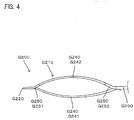
- FIG. 4 is a side view of the long part G210 of the second holder G200.
- FIG. 5 is a sectional view taken along line II-II in FIG. 3 .
- the first extending part G241 and the second extending part G242 are curved in a direction away from each other. Specifically, as shown in FIG. 4 , the first extending part G241 is curved such that a central region of the first extending part G241 protrudes downward as viewed in FIG. 4 , and the second extending part G242 is curved such that a central region of the second extending part G242 protrudes upward as viewed in FIG. 4 .
- the long part G210 macroscopically has a substantially three-dimensional shape.
- the base-side projection G152 of the first holder G100 and the base-side projection G252 of the second holder G200 are located in substantially the same region on the second axis A100x.
- the tip-side projection G151 of the first holder G100 is located toward the base G130 compared with the tip-side projection G251 of the second holder G200.
- the tip-side projection G151 and the base-side projection G152 are received in the first receiving regions C310 shown in FIG. 8 when the first holder G100 is attached to the cleaning sheet B100, while the tip-side projection G251 is received in the second receiving region C320 and the base-side projection G252 is received in the first receiving region C310 when the second holder G200 is attached to the cleaning sheet B100.
- the structures of the first and second receiving regions C310, C320 are described below in more detail.
- the first holder G100 and the second holder G200 are formed of a resin material.
- polypropylene (PP) is used.
- FIG. 6 is a plan view showing the cleaning sheet B100
- FIG. 7 is a sectional view taken along line I-I in FIG. 6 .
- the cleaning sheet B100 includes a sheet-like member B110 and a fiber bundle B200.
- the sheet-like member B110 has a first sheet B111, a second sheet B112 and a third sheet B113.
- the first sheet B111 and the second sheet B112 are superposed one on the other.
- the fiber bundle B200 is disposed between the second sheet B112 and the third sheet B113.
- the sheet-like member B110 and the fiber bundle B200 are bonded by a prescribed bonded part D100.
- a receiving part C100 for receiving a long part G110 of the holder G100 shown in FIG. 1 is formed between the first sheet B111 and the second sheet B112.
- the receiving part C100 is also capable of receiving a long part G210 of the holder G200 shown in FIG. 3 .
- the receiving part C100 is formed by bonding the first and second sheets B111, B112 at the bonded part D100. Specifically, the bonded part D100 defines an outer edge of the receiving part C100.
- the structures of the bonded part D100 and the receiving part C100 are described below in further detail.
- the sheet-like member B110, the bonded part D100 and the receiving part C100 are example embodiments that correspond to the "sheet-like member", the "bonded part” and the "receiving part", respectively, according to this invention.
- the cleaning sheet B100 defines a first axis A100y parallel to an insertion direction A110y of the long part G110, G210 into the receiving part C100.
- a direction opposite to the insertion direction A110y in the direction of the first axis A100y defines a removal direction A120y.
- a direction crossing the first axis A100y defines a second axis A100x.
- the insertion direction A110y, the removal direction A120y and the first axis A100y are example embodiments that correspond to the "insertion direction", the "removal direction” and the "insertion axis", respectively, according to this invention.
- the receiving part C100 has an opening C110 and a receiving space C200 formed contiguously to the opening C110 and extending in the direction of the first axis A100y.
- the opening C110 and the receiving space C200 are example embodiments that correspond to the "opening" and the "receiving space", respectively, according to this invention.
- the first sheet B111 is shorter than the second sheet B112 in the direction of the first axis A100y.
- the opening C110 includes a first opening C111 and a second opening C112 formed on the opposite side to the first opening C111 in the direction of the first axis A100y.
- the first opening C111 and the second opening C112 are example embodiments that correspond to the "first opening” and the "second opening", respectively, according to this invention.
- the first, second and third sheets B111, B112, B113 have a plurality of cuts B310 extending in the direction of the second axis A100x. Strips B300 are formed between adjacent ones of the cuts B310.
- the sheet-like member B110 is formed by nonwoven fabric of thermal melting fibers (thermoplastic fibers).
- the fiber bundle B200 is formed by a fiber structure in order to be made capable of cleaning a subject to be cleaned.
- the fiber structure refers to a structure formed of "fibers".
- the "fibers” include typical single fibers, and typical fibers aligned in the length direction and/or the radial direction (twist yarn, spun yarn, yarn to which a plurality of filaments are partially connected).
- the "typical fiber” here refers to a component of a fiber structure such as yarn and textile and is a thin and flexible fiber having a substantially longer length compared with the thickness.
- a long continuous fiber is defined as a filament and a short fiber as a staple.
- the fiber bundle B200 is formed by a fiber assembly of fibers having orientation in a prescribed direction.
- the fiber assembly is formed by an assembly of fibers having orientation in the direction of the second axis A100x.
- the fiber assembly is formed of layered fibers having orientation in the direction of the second axis A100x.
- the fibers are flexible and thus easily bent and deformed. Therefore, the orientation direction of the fibers refers to the fiber orientation in product design.
- the fiber assembly is an assembly of filaments made of polyethylene terephthalate (PET) and obtained by opening a tow in practical use.
- PET polyethylene terephthalate
- the receiving part C100 of the cleaning sheet B100 is now described with reference to FIG. 8 .
- the outer edge of the receiving part C100 is defined by a plurality of the bonded parts D100.
- the cleaning sheet B100 has a separation bonded part (sixth bonded part) D106 passing through its center in the direction of the second axis A100x and extending in the direction of the first axis A100y.
- the receiving space C200 is separated into right and left parts as viewed in FIG. 8 by the separation bonded part D106.
- the separation bonded part D106 is an example embodiment that corresponds to the "separation bonded part" according to this invention.
- the opening C110 includes the first opening C111, the second opening C112 formed on the opposite side to the first opening C111 in the direction of the first axis A100y, a first opening-side region C111 a including the first opening C111 and a second opening-side region C112a including the second opening C112.
- the first opening C111, the second opening C112, the first opening-side region C111a and the second opening-side region C112a are example embodiments that correspond to the "first opening", the "second opening”, the "first opening-side region” and the "second opening-side region", respectively, according to this invention.
- the receiving space C200 includes a first receiving region C310 and a second receiving region C320.
- the first receiving region C310 is formed for the first holder G100
- the second receiving region C320 is formed for the second holder G200.
- the first receiving region C310 and the second receiving region C320 are example embodiments that correspond to the "first receiving region” and the "second receiving region", respectively, according to this invention.
- the first holder G100 shown in FIG. 1 has a first long part G110 to be inserted into the receiving space C200 and a first projection G150 formed on the first long part G110.
- the second holder G200 shown in FIG. 3 has a second long part G210 to be inserted into the receiving space C200 and a second projection G250 formed on the second long part G210.
- the first receiving region C310 receives the first projection G150.
- the second receiving region C320 receives the second projection G250. That "the projection is received in the receiving region" does not represent that all of the projections of the holder are received in the specific receiving region.
- the second holder G200 has two second projections G250 as described below, but at least one of them may be received in the second receiving region C320.
- the first receiving region C310 and the second receiving region C320 are adjacent to each other in the direction of the first axis A100y.
- the first receiving region C310 has a front end C311 and a rear end C312, and the second receiving region C320 has a front end C321 and a rear end C322.
- the first long part G110 and the first projection G150 are example embodiments that correspond to the "first long part” and the "first projection", respectively, according to this invention.
- the second long part G2210 and the second projection G250 are example embodiments that correspond to the "second long part” and the "second projection", respectively, according to this invention.
- the bonded part D100 of the cleaning sheet B100 is now described with reference to FIG. 9 .
- the bonded part D100 is formed by welding the sheet-like member B110 and the fiber bundle B200.
- the bonded part D100 includes a first bonded part D101, a second bonded part D102, a third bonded part D103, a fourth bonded part D104, a fifth bonded part D105 and a sixth bonded part D106.
- a pair of each of the first to fourth bonded parts D101, D102, D103, D104 are formed on the second axis A100x.
- the first to fifth bonded parts D101 to D105 are symmetrically arranged in the first opening-side region C111a and the second opening-side region C112a.
- the first bonded parts D101, the second bonded parts D102, the third bonded parts D103 and the fourth bonded parts D104 are arranged in this order when viewed from the opening C110.
- the fifth bonded part D105 is formed on the sixth bonded part D106 on the second axis A100x passing through the second bonded parts D102. Specifically, as shown in FIG. 9 , the fifth bonded parts D105 and the sixth bonded part D106 are overlapped with each other.
- the sixth bonded part D106 bonds the first sheet B111, the second sheet B112, the fiber bundle D200 and the third sheet B113.
- the first to fifth bonded parts D101 to D105 bond the first sheet B 111, the second sheet B112 and part of the fiber bundle B200.
- the receiving space C200 has a first space region C201 having a prescribed width and a second space region C202 having a smaller width than the first space region C201, in the direction of the second axis A100x.
- the first space region C201 is disposed closer to the opening C110 than the second space region C202 in the direction of the first axis A100y.
- the first space region C201 is defined between the pair of the first bonded parts D101.
- the second space region C202 is defined between the pair of the second bonded parts D102.
- the first space region C201 and the second space region C202 are symmetrically formed in the first opening-side region C111a and the second opening-side region C112a.
- the fifth bonded part D105 is formed in the second space region C202.
- the fifth bonded part D105 forms a high rigidity part C400 having higher rigidity than the other parts in the receiving part C100.
- the first to fourth bonded parts D101 to D104 forming the outer edge of the receiving part C100 are not included in "the other parts in the receiving part C100".
- the fifth bonded part D105 is configured to be wider than the sixth bonded part D106 in the direction of the second axis A100x.
- the region of the fifth bonded part D105 (the high rigidity part C400) has higher rigidity than the other parts in the receiving part C100.
- the first receiving region C310 receives the projection G150 of the holder G100, and the second receiving region C320 receives the projection G250 of the holder G200. Therefore, the first receiving region C310 and the second receiving region C320 can be said to be projection receiving regions.
- the first receiving region C310 and the second receiving region C320 are formed by a first receiving region formation part D110 and a second receiving region formation part D210, respectively.
- the first receiving region formation part D110 and the second receiving region formation part D210 are example embodiments that correspond to the "first receiving region formation part” and the "second receiving region formation part", respectively, according to this invention.
- the first receiving region C310 has a front end C311 and a rear end C312, and the second receiving region C320 has a front end C321 and a rear end C322.
- the first receiving region formation part D110 has a first front end bonded part D111 forming the front end C311 of the first receiving region C310, and a first rear end bonded part D112 forming the rear end C312 of the first receiving region C310.
- the first front end bonded part D111 is formed by the third bonded part D103
- the first rear end bonded part D112 is formed by the second bonded part D102.
- the second receiving region formation part D210 has a second front end bonded part D211 forming the front end C321 of the second receiving region C320, and a second rear end bonded part D212 forming the rear end C322 of the second receiving region C320.
- the second front end bonded part D211 is formed by the second bonded part D102
- the second rear end bonded part D212 is formed by the first bonded part D101.
- the second bonded part D102 serves as both the first rear end bonded part D112 and the second front end bonded part D211.
- the first front end bonded part D111 and the first rear end bonded part D112 are example embodiments that correspond to the "first front end bonded part” and the “first rear end bonded part", respectively, according to this invention.
- the second front end bonded part D211 and the second rear end bonded part D212 are example embodiments that correspond to the "second front end bonded part” and the “second rear end bonded part”, respectively, according to this invention.
- the first receiving region formation part D110 and the second receiving region formation part D210 are formed by respective pairs of bonded parts, but they may be formed by respective single bonded parts.
- FIGS. 10 to 17 An insertion-side region D300 and a removal-side region D400 in the bonded part D100 are now described with reference to FIGS. 10 to 17 .
- the insertion-side region D300 and the removal-side region D400 which are described below are formed in the first to third bonded parts D101 to D103.
- the second bonded part D102 is shown and described as a representative example of the bonded parts having the insertion-side region D300 and the removal-side region D400.
- the first holder G100 is shown and described as a representative example of the holders.
- the second bonded part D102 has the insertion-side region D300 which gets into contact with the projection G150 when the holder G100 is moved in the insertion direction A110y such that the long part G110 of the holder G100 is received in the receiving part C100. Further, the second bonded part D102 has the removal-side region D400 which gets into contact with the projection G150 when the long part G110 received in the receiving part C100 is moved in the removal direction A120y.
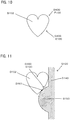
- the insertion-side region D300 defines an insertion starting point D301 with which the projection G150 moving in the insertion direction A110y first gets into contact as shown in FIG. 11 , and an insertion end point D302 which is an end point of contact of the projection G150 moving in the insertion direction A110y as shown in FIG. 12 . Further, as shown in FIG. 13 , the insertion-side region D300 defines a first insertion line D303 connecting the insertion starting point D301 and the insertion end point D302, a second insertion line D304 passing through the insertion starting point D301 along the second axis A100x, and an insertion angle D305 made by the first insertion line D303 and the second insertion line D304.
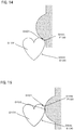
- the removal-side region D400 defines a removal starting point D401 with which the projection G150 moving in the removal direction A120y first gets into contact as shown in FIG. 14 , and a removal end point D402 which is an end point of contact of the projection G150 moving in the removal direction A120y as shown in FIG. 15 . Further, as shown in FIG. 16 , the removal-side region D400 defines a first removal line D403 connecting the removal starting point D401 and the removal end point D402, a second removal line D404 passing through the removal end point D402 along the second axis A100x, and a removal angle D405 made by the first removal line D403 and the second removal line D404.
- the insertion angle D305 shown in FIG. 13 is formed to be smaller than the removal angle D405 shown in FIG. 16 .
- the insertion-side region D300 and the removal-side region D400 described above with reference to FIGS. 10 to 16 are formed in the first to third bonded parts D101 to D103.
- the insertion-side regions D300 in the first to third bonded parts D101 to D103 are referred to as a first insertion-side region D310, a second insertion-side region D320 and a third insertion-side region D330, respectively.
- the removal-side regions D400 in the first to third bonded parts D101 to D103 are referred to as a first removal-side region D410, a second removal-side region D420 and a third removal-side region D430, respectively.
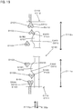
- FIGS. 18 and 19 are explanatory drawings for illustrating the operation when the first holder G100 is used
- FIG. 20 is an explanatory drawing for illustrating the operation when the second holder G200 is used.
- operation of only one of the long parts G140 or G240 is shown and described.
- the tip G120 of the first holder G100 is inserted into the receiving part C100 of the cleaning sheet B100 through the first opening C111.
- the first bonded parts D101 define the first space region C201 so that the first opening C111 is formed wide in the direction of the second axis A100x. Therefore, the user can easily insert the tip G120 into the first opening C111.
- the tip-side projection G151 gets into contact with the first insertion-side region D310 of the first bonded part D101.
- the user can smoothly insert the long part G110 of the first holder G100 into the receiving part C100 without large resistance.
- the long part G110 is deformed inward (toward the sixth bonded part D106) through the first insertion-side region D310 having the insertion angle D305.
- the first bonded parts D101 and the second bonded parts D102 define the first space region C201 and the second space region C202, respectively.
- the second space region C202 is configured to have a smaller width than the first space region C201 in the direction of the second axis A100x.
- the long part G110 is moved from the first space region C201 to the second space region C202 by the user while being kept in the deformed state. Therefore, when the tip-side projection G151 of the long part G110 reaches the second space region C202 and passes through the second space region C202, the user can smoothly move the long part G110 without large resistance. Therefore, the first insertion-side region D310 of the first bonded part D101 can be said to be a guide part E100 for guiding the holder G100 from the first space region C201 to the second space region C202.
- the long part G110 is moved through the second space region C202 by the user while being kept in the deformed state.
- the fifth bonded part D105 is formed in the second space region C202, the fifth bonded part D105 forming the high rigidity part C400 as described above prevents the receiving part C100 from largely deforming when the tip-side projection G151 passes over the second bonded part D102.
- the long part G110 is further moved by the user and the tip-side projection G151 reaches the second opening-side region C112a through the first opening-side region C111a.
- the base-side projection G152 passes over the first and second bonded parts D101, D102 in the first opening-side region C111a.
- the guide part E100 and the high rigidity part C400 function in the same manner as in the above-described case of the tip-side projection G151.
- FIG. 19 shows the state that insertion of the long part G110 into the receiving part C100 is completed.
- the tip-side projection G151 is received in the first receiving region C310 of the second opening-side region C112a.
- the base-side projection G152 is received in the first receiving region C310 of the first opening-side region C111a.
- the user performs a cleaning operation with the cleaning tool.
- the positional relation between the cleaning sheet B100 and the long part G110 may be changed from that at the beginning due to friction between the cleaning sheet B100 and an object to be cleaned.
- the holder G100 may tend to further move in the insertion direction A110y.
- the tip-side projection G151 gets into contact with the second removal-side region D420 of the second bonded part D102 in the second opening-side region C112a.
- the tip-side projection G151 is reliably brought into contact with the second bonded part D102 since the second bonded parts D102 define the second space region C202.
- the second removal-side region D420 is configured to have the removal angle D405 such that the tip-side projection G151 cannot easily pass over the second bonded part D102 in the second opening-side region C112a.
- the holder G100 is prevented from further moving in the insertion direction A110y.
- the removal-side region D400 in the second opening-side region C112a forms a preventing part F100 for preventing the holder G100 inserted from the first opening C111 from being further inserted.
- the holder G100 may tend to move in the removal direction A120y.
- the base-side projection G152 gets into contact with the second removal-side region D420 of the second bonded part D102 in the first opening-side region C111a.
- the second bonded parts D102 define the second space region C202, the base-side projection G152 is reliably brought into contact with the second bonded part D102.
- the second removal-side region D420 is configured to have the removal angle D405 such that the base-side projection G152 cannot easily pass over the second bonded part D102 in the first opening-side region C111a.
- the holder G100 is prevented from moving in the removal direction A120y.
- FIG. 20 shows the state that insertion of the second holder G200 into the receiving part C100 is completed.
- the tip-side projection G251 is received in the second receiving region C320 of the second opening-side region C112a.
- the base-side projection G252 is received in the first receiving region C310 of the first opening-side region C111a.
- the functioning of the guide part E100 at the time of insertion of the long part G210 into the receiving part C100 and the functioning of the preventing part F100 during cleaning operation are respectively similar to those described above with reference to FIGS. 18 and 19 and will not be further elaborated here.
- the preventing part F100 is formed in both the first removal-side region D410 of the first bonded part D101 and the second removal-side region D420 of the second bonded part D102.
- the tip-side projection G251 gets into contact with the first removal-side region D410 (the preventing part F100).
- the second extending part G242 is curved to protrude outward in the direction of the second axis A100x. Therefore, when the holder G200 tends to further move in the insertion direction A110y, the curved part of the second extending part G242 gets into contact with the second removal-side region D420 (the preventing part F100).
- the second holder G200 is configured to be prevented from easily moving in the insertion direction A110y during cleaning operation.
- either one of the first removal-side region D410 and the second removal-side region D420 may function as the preventing part F100.
- the cleaning sheet B100 and the holder G100 are example embodiments that correspond to the "cleaning sheet” and the "holder”, respectively, according to this invention.
- the first holder G100 and the second holder G200 are example embodiments that correspond to the "first holder” and the “second holder”, respectively, according to this invention.
- the sheet-like member B110, the bonded part D100 and the receiving part C100 are example embodiments that correspond to the "sheet-like member", the "bonded part” and the “receiving part”, respectively, according to this invention.
- the insertion direction A110y, the removal direction A120y and the first axis A100y are example embodiments that correspond to the "insertion direction", the "removal direction” and the "insertion axis", respectively, according to this invention.
- the opening C110 and the receiving space C200 are example embodiments that correspond to the "opening” and the “receiving space", respectively, according to this invention.
- the separation bonded part D106 is an example embodiment that corresponds to the "separation bonded part” according to this invention.
- the first opening C111, the second opening C112, the first opening-side region C111a and the second opening-side region C112a are example embodiments that correspond to the "first opening”, the "second opening”, the "first opening-side region”, the “second opening-side region”, respectively, according to this invention.
- the first receiving region C310 and the second receiving region C320 are example embodiments that correspond to the "first receiving region” and the "second receiving region", respectively, according to this invention.
- the first long part G110 and the first projection G150 are example embodiments that correspond to the "first long part” and the “first projection”, respectively, according to this invention.
- the second long part G2210 and the second projection G250 are example embodiments that correspond to the "second long part” and the “second projection", respectively, according to this invention.
- the first receiving region formation part D110 and the second receiving region formation part D210 are example embodiments that correspond to the "first receiving region formation part” and the "second receiving region formation part", respectively, according to this invention.
- the first front end bonded part D111 and the first rear end bonded part D112 are example embodiments that correspond to the "first front end bonded part” and the "first rear end bonded part", respectively, according to this invention.
- the second front end bonded part D211 and the second rear end bonded part D212 are example embodiments that correspond to the "second front end bonded part” and the "second rear end bonded part", respectively, according to this invention.
Landscapes
- Cleaning Implements For Floors, Carpets, Furniture, Walls, And The Like (AREA)
Abstract
Description
- The present invention relates to a cleaning sheet and a cleaning tool package for cleaning an object to be cleaned. This application claims priority based on Japanese Patent Application No.
2014-163138 filed August 8, 2014 - Japanese Unexamined Patent Application Publication (
JP-A) No. 2008-253286 - Patent Document 1:
JP-A No. 2008-253286 - Accordingly, it is an object of the present invention to provide a more rational constructing technique for a cleaning sheet and a cleaning tool package.
- In order to solve the above problem, according to the present invention, a cleaning sheet is provided which is configured to be attached to plural kinds of holders. The cleaning sheet has sheet-like members, a receiving part configured to receive the holders by superposing the sheet-like members, and a bonded part that defines an outer edge of the receiving part by bonding the superposed sheet-like members. An insertion direction of the holders in the receiving part defines an insertion axis. The receiving part has an opening and a receiving space formed contiguously to the opening and extending in a direction of the insertion axis. The receiving space has a first receiving region for a first one of the holders and a second receiving region for a second one of the holders which is different from the first holder.
- According to this invention, the first and second holders having different structures can be used with the single cleaning sheet.
- In one aspect of the solution in the cleaning sheet according to this invention, the first holder has a first long part to be inserted into the receiving space and a first projection formed on the first long part. The second holder has a second long part to be inserted into the receiving space and a second projection formed on the second long part. Further, the first receiving region is configured to receive the first projection, and the second receiving region is configured to receive the second projection.
- In one aspect of the solution in the cleaning sheet according to this invention, the first receiving region and the second receiving region are adjacent to each other in the direction of the insertion axis.
- In one aspect of the solution in the cleaning sheet according to this invention, the bonded part has a first receiving region formation part for forming the first receiving region and a second receiving region formation part for forming the second receiving region.
- In one aspect of the solution in the cleaning sheet according to this invention, the first receiving region has a pair of end regions, and the first receiving region formation part has a first front end bonded part forming one of the end regions of the first receiving region, and a first rear end bonded part forming the other end region of the first receiving region.
- In one aspect of the solution in the cleaning sheet according to this invention, the second receiving region has a pair of end regions, and the second receiving region formation part has a second front end bonded part forming one of the end regions of the second receiving region, and a second rear end bonded part forming the other end region of the second receiving region.
- In one aspect of the solution in the cleaning sheet according to this invention, the first rear end bonded part also serves as the second front end bonded part.
- In one aspect of the solution in the cleaning sheet according to this invention, the opening includes a first opening, a second opening formed on the opposite side to the first opening in the direction of the insertion axis, a first opening-side region including the first opening and a second opening-side region including the second opening. The first receiving region and the second receiving region are both formed in the first opening-side region and the second opening-side region.
- According to this aspect of the invention, whether the first or second holder is inserted from the first opening or the second opening, the first or second holder can be attached to the cleaning sheet in either case.
- According to a further aspect of the cleaning sheet of the present invention, the receiving part has a separation bonded part for separating the receiving space.
- According to this aspect of the invention, the holder of which part to be inserted into the cleaning sheet has a bifurcated shape, for example, may be suitably used.
- In order to solve the above problem, according to this invention, a cleaning tool package is provided which has a first holder, a second holder having a different structure from the first holder and a cleaning sheet configured to be attached to the first and second holders, and the cleaning tool package is formed by combination of either one of the first and second holders and the cleaning sheet.
- The cleaning sheet has sheet-like members, a receiving part configured to receive the holders by superposing the sheet-like members, and a bonded part that defines an outer edge of the receiving part by bonding the superposed sheet-like members. An insertion direction of the holders in the receiving part defines an insertion axis. The receiving part has an opening and a receiving space formed contiguously to the opening and extending in a direction of the insertion axis. The receiving space has a first receiving region for the first holder and a second receiving region for the second holder.
- According to this invention, the first and second holders having different structures can be used with the single cleaning sheet.
- According to this invention, a more rational constructing technique for a cleaning sheet and a cleaning tool package is provided.
-
-
FIG. 1 is an explanatory drawing for illustrating the structure of a first holder. -
FIG. 2 is an explanatory drawing for illustrating the structure of a long part of the first holder. -
FIG. 3 is an explanatory drawing for illustrating the structure of a second holder. -
FIG. 4 is an explanatory drawing for illustrating the structure of a long part of the second holder. -
FIG. 5 is a sectional view taken along line II-II inFIG. 3 . -
FIG. 6 is a front view showing an overall structure of a cleaning sheet according to an embodiment of the present invention. -
FIG. 7 is a sectional view taken along line I-I inFIG. 6 . -
FIG. 8 is an explanatory drawing for illustrating a receiving part in the cleaning sheet. -
FIG. 9 is an explanatory drawing for illustrating a bonded part in the cleaning sheet. -
FIG. 10 is an explanatory drawing for illustrating the structure of the bonded part. -
FIG. 11 is an explanatory drawing for illustrating the structure of an insertion-side region. -
FIG. 12 is an explanatory drawing for illustrating the structure of the insertion-side region. -
FIG. 13 is an explanatory drawing for illustrating the structure of the insertion-side region. -
FIG. 14 is an explanatory drawing for illustrating the structure of a removal-side region. -
FIG. 15 is an explanatory drawing for illustrating the structure of the removal-side region. -
FIG. 16 is an explanatory drawing for illustrating the structure of the removal-side region. -
FIG. 17 is an explanatory drawing for illustrating the structures of the insertion-side region and the removal-side region in the cleaning sheet. -
FIG. 18 is an explanatory drawing for illustrating the operation of a cleaning tool. -
FIG. 19 is an explanatory drawing for illustrating the operation of the cleaning tool. -
FIG. 20 is an explanatory drawing for illustrating the operation of the cleaning tool. - Embodiments of a cleaning sheet and a cleaning tool according to the present invention are now described with reference to
FIGS. 1 to 20 . The cleaning tool is formed by attaching a holder G100 shown inFIG. 1 to a cleaning sheet B100 shown inFIG. 6 . The cleaning sheet B100 and the holder G100 are example embodiments that correspond to the "cleaning sheet" and the "holder", respectively, according to this invention. The cleaning sheet B100 may be sold separately, or packed together with the holder G100 and sold. The cleaning sheet B100 and the holder G100 packed together for sale form a cleaning tool package. The holder G100 includes holders of two different kinds shown inFIGS. 1 and3 which are properly used according to the usage. For the sake of convenience, the holders shown inFIGS. 1 and3 are referred to as a first holder G100 and a second holder G200, respectively. The cleaning tool package is provided by combination of either one of the first and second holders G100, G200 and the cleaning sheet B100. The cleaning tool package may also be provided by combination of both of the first and second holders G100, G200 and the cleaning sheet B100. The first holder G100 and the second holder G200 are example embodiments that correspond to the "first holder" and the "second holder", respectively, according to this invention. - The cleaning sheet B100 may be of disposable type designed for single use, or disposable type designed for multiple use which can be used several times, while holding dust or dirt collected from a cleaning surface to be cleaned.
- The holders are now described with reference to
FIGS. 1 to 5 .FIGS. 1 and2 show the first holder G100, andFIGS. 3 to 5 show the second holder G200. - As shown in
FIG. 1 , the first holder G100 has the long part G110 to be held in the receiving part C100 of the cleaning sheet B100, and a handle part G160 to be held by a user. The long part G110 has a tip G120, a base G130 and an extending part G140 extending between the tip G120 and the base G130. The extending part G140 extends in a bifurcated shape from the base G130. Thus, the long part G110 has the single base part G130 and has two each of the tips G120 and the extending parts G140. The extending part G140 has the projection G150. The projection G150 includes a tip-side projection G151 on the tip G120 side and a base-side projection G152 on the base G130 side. The handle part G160 has a front end G161, a rear end G162 and a grip G163 extending between the front end G161 and the rear end G162. The base G130 of the long part G110 and the front end G161 of the handle part G160 are configured to be removable from each other. -
FIG. 2 is a side view of the long part G110 of the first holder G100. As shown inFIG. 2 , the long part G110 has a tapered structure having a thickness gradually decreasing from the base 130 toward the tip G120, but macroscopically has a substantially flat shape. - As shown in
FIG. 3 , the second holder G200 has the long part G210 to be held in the receiving part C100 of the cleaning sheet B100, and a handle part G260 to be held by a user. The long part G210 has a tip G220, a base G230 and an extending part G240 extending between the tip G220 and the base G230. The extending part G240 extends in a bifurcated shape from the base G230. Thus, the long part G210 has the single base part G230 and has two each of the tips G220 and the extending parts G240. - The extending part G240 has a first extending part G241 and a second extending part G242. In the bifurcated extending part G240, the first extending parts G241 are configured to be located closer to each other, and the second extending parts G242 are configured to be located away from each other. More specifically, as shown in
FIG. 3 , the two first extending parts G241 are curved to protrude in a direction toward each other in the direction of the second axis A100x, and the two second extending parts G242 are curved to protrude in a direction away from each other in the direction of the second axis A100x. - The second extending part G242 of the extending part G240 has a projection G250. The projection G250 includes a tip-side projection G251 on the tip G220 side and a base-side projection G252 on the base G230 side. The handle part G260 has a front end G261, a rear end G262 and a grip G263 extending between the front end G261 and the rear end G262. The base G230 of the long part G210 and the front end G261 of the handle part G260 are configured to be removable from each other.
-
FIG. 4 is a side view of the long part G210 of the second holder G200.FIG. 5 is a sectional view taken along line II-II inFIG. 3 . As shown inFIGS. 4 and5 , the first extending part G241 and the second extending part G242 are curved in a direction away from each other. Specifically, as shown inFIG. 4 , the first extending part G241 is curved such that a central region of the first extending part G241 protrudes downward as viewed inFIG. 4 , and the second extending part G242 is curved such that a central region of the second extending part G242 protrudes upward as viewed inFIG. 4 . Thus, the long part G210 macroscopically has a substantially three-dimensional shape. - When a connection part between the base G130 and the extending parts G140 in the first holder G100 and a connection part between the base G230 and the extending parts G240 in the second holder G200 are aligned side by side on the second axis A100x, the base-side projection G152 of the first holder G100 and the base-side projection G252 of the second holder G200 are located in substantially the same region on the second axis A100x. At this time, however, the tip-side projection G151 of the first holder G100 is located toward the base G130 compared with the tip-side projection G251 of the second holder G200.
- Therefore, the tip-side projection G151 and the base-side projection G152 are received in the first receiving regions C310 shown in
FIG. 8 when the first holder G100 is attached to the cleaning sheet B100, while the tip-side projection G251 is received in the second receiving region C320 and the base-side projection G252 is received in the first receiving region C310 when the second holder G200 is attached to the cleaning sheet B100. The structures of the first and second receiving regions C310, C320 are described below in more detail. - The first holder G100 and the second holder G200 are formed of a resin material. In this embodiment, polypropylene (PP) is used.
- The basic structure of the cleaning sheet B100 is now described with reference to
FIGS. 6 and7 .FIG. 6 is a plan view showing the cleaning sheet B100, andFIG. 7 is a sectional view taken along line I-I inFIG. 6 . - As shown in
FIG. 7 , the cleaning sheet B100 includes a sheet-like member B110 and a fiber bundle B200. The sheet-like member B110 has a first sheet B111, a second sheet B112 and a third sheet B113. The first sheet B111 and the second sheet B112 are superposed one on the other. The fiber bundle B200 is disposed between the second sheet B112 and the third sheet B113. The sheet-like member B110 and the fiber bundle B200 are bonded by a prescribed bonded part D100. A receiving part C100 for receiving a long part G110 of the holder G100 shown inFIG. 1 is formed between the first sheet B111 and the second sheet B112. Further, the receiving part C100 is also capable of receiving a long part G210 of the holder G200 shown inFIG. 3 . The receiving part C100 is formed by bonding the first and second sheets B111, B112 at the bonded part D100. Specifically, the bonded part D100 defines an outer edge of the receiving part C100. The structures of the bonded part D100 and the receiving part C100 are described below in further detail. The sheet-like member B110, the bonded part D100 and the receiving part C100 are example embodiments that correspond to the "sheet-like member", the "bonded part" and the "receiving part", respectively, according to this invention. - As shown in
FIG. 6 , the cleaning sheet B100 defines a first axis A100y parallel to an insertion direction A110y of the long part G110, G210 into the receiving part C100. A direction opposite to the insertion direction A110y in the direction of the first axis A100y defines a removal direction A120y. A direction crossing the first axis A100y defines a second axis A100x. The insertion direction A110y, the removal direction A120y and the first axis A100y are example embodiments that correspond to the "insertion direction", the "removal direction" and the "insertion axis", respectively, according to this invention. - As shown in
FIG. 6 , the receiving part C100 has an opening C110 and a receiving space C200 formed contiguously to the opening C110 and extending in the direction of the first axis A100y. The opening C110 and the receiving space C200 are example embodiments that correspond to the "opening" and the "receiving space", respectively, according to this invention. As shown inFIG. 6 , the first sheet B111 is shorter than the second sheet B112 in the direction of the first axis A100y. The opening C110 includes a first opening C111 and a second opening C112 formed on the opposite side to the first opening C111 in the direction of the first axis A100y. The first opening C111 and the second opening C112 are example embodiments that correspond to the "first opening" and the "second opening", respectively, according to this invention. - The first, second and third sheets B111, B112, B113 have a plurality of cuts B310 extending in the direction of the second axis A100x. Strips B300 are formed between adjacent ones of the cuts B310.
- The sheet-like member B110 is formed by nonwoven fabric of thermal melting fibers (thermoplastic fibers).
- The fiber bundle B200 is formed by a fiber structure in order to be made capable of cleaning a subject to be cleaned. In this invention, the fiber structure refers to a structure formed of "fibers". In this invention, the "fibers" include typical single fibers, and typical fibers aligned in the length direction and/or the radial direction (twist yarn, spun yarn, yarn to which a plurality of filaments are partially connected). The "typical fiber" here refers to a component of a fiber structure such as yarn and textile and is a thin and flexible fiber having a substantially longer length compared with the thickness. Typically, a long continuous fiber is defined as a filament and a short fiber as a staple.
- In the cleaning sheet B100 according to this embodiment, the fiber bundle B200 is formed by a fiber assembly of fibers having orientation in a prescribed direction. Specifically, the fiber assembly is formed by an assembly of fibers having orientation in the direction of the second axis A100x.
- The fiber assembly is formed of layered fibers having orientation in the direction of the second axis A100x. The fibers are flexible and thus easily bent and deformed. Therefore, the orientation direction of the fibers refers to the fiber orientation in product design.
- Preferably, the fiber assembly is an assembly of filaments made of polyethylene terephthalate (PET) and obtained by opening a tow in practical use.
- The receiving part C100 of the cleaning sheet B100 is now described with reference to
FIG. 8 . The outer edge of the receiving part C100 is defined by a plurality of the bonded parts D100. Further, the cleaning sheet B100 has a separation bonded part (sixth bonded part) D106 passing through its center in the direction of the second axis A100x and extending in the direction of the first axis A100y. The receiving space C200 is separated into right and left parts as viewed inFIG. 8 by the separation bonded part D106. The separation bonded part D106 is an example embodiment that corresponds to the "separation bonded part" according to this invention. - The opening C110 includes the first opening C111, the second opening C112 formed on the opposite side to the first opening C111 in the direction of the first axis A100y, a first opening-side region C111 a including the first opening C111 and a second opening-side region C112a including the second opening C112. The first opening C111, the second opening C112, the first opening-side region C111a and the second opening-side region C112a are example embodiments that correspond to the "first opening", the "second opening", the "first opening-side region" and the "second opening-side region", respectively, according to this invention.
- The receiving space C200 includes a first receiving region C310 and a second receiving region C320. The first receiving region C310 is formed for the first holder G100, and the second receiving region C320 is formed for the second holder G200. The first receiving region C310 and the second receiving region C320 are example embodiments that correspond to the "first receiving region" and the "second receiving region", respectively, according to this invention.
- More specifically, the first holder G100 shown in
FIG. 1 has a first long part G110 to be inserted into the receiving space C200 and a first projection G150 formed on the first long part G110. The second holder G200 shown inFIG. 3 has a second long part G210 to be inserted into the receiving space C200 and a second projection G250 formed on the second long part G210. When the first holder G100 is attached to the cleaning sheet B100, the first receiving region C310 receives the first projection G150. When the second holder G200 is attached to the cleaning sheet B100, the second receiving region C320 receives the second projection G250. That "the projection is received in the receiving region" does not represent that all of the projections of the holder are received in the specific receiving region. For example, the second holder G200 has two second projections G250 as described below, but at least one of them may be received in the second receiving region C320. - The first receiving region C310 and the second receiving region C320 are adjacent to each other in the direction of the first axis A100y. The first receiving region C310 has a front end C311 and a rear end C312, and the second receiving region C320 has a front end C321 and a rear end C322. The first long part G110 and the first projection G150 are example embodiments that correspond to the "first long part" and the "first projection", respectively, according to this invention. The second long part G2210 and the second projection G250 are example embodiments that correspond to the "second long part" and the "second projection", respectively, according to this invention.
- The bonded part D100 of the cleaning sheet B100 is now described with reference to
FIG. 9 . The bonded part D100 is formed by welding the sheet-like member B110 and the fiber bundle B200. The bonded part D100 includes a first bonded part D101, a second bonded part D102, a third bonded part D103, a fourth bonded part D104, a fifth bonded part D105 and a sixth bonded part D106. A pair of each of the first to fourth bonded parts D101, D102, D103, D104 are formed on the second axis A100x. The first to fifth bonded parts D101 to D105 are symmetrically arranged in the first opening-side region C111a and the second opening-side region C112a. The first bonded parts D101, the second bonded parts D102, the third bonded parts D103 and the fourth bonded parts D104 are arranged in this order when viewed from the opening C110. The fifth bonded part D105 is formed on the sixth bonded part D106 on the second axis A100x passing through the second bonded parts D102. Specifically, as shown inFIG. 9 , the fifth bonded parts D105 and the sixth bonded part D106 are overlapped with each other. - As shown in
FIG. 7 , the sixth bonded part D106 bonds the first sheet B111, the second sheet B112, the fiber bundle D200 and the third sheet B113. The first to fifth bonded parts D101 to D105 bond the first sheet B 111, the second sheet B112 and part of the fiber bundle B200. - As shown in
FIG. 9 , the receiving space C200 has a first space region C201 having a prescribed width and a second space region C202 having a smaller width than the first space region C201, in the direction of the second axis A100x. The first space region C201 is disposed closer to the opening C110 than the second space region C202 in the direction of the first axis A100y. The first space region C201 is defined between the pair of the first bonded parts D101. The second space region C202 is defined between the pair of the second bonded parts D102. Thus, the distance between the pair of the first bonded parts D101 is longer than the distance between the pair of the second bonded parts D102 in the direction of the second axis A100x. The first space region C201 and the second space region C202 are symmetrically formed in the first opening-side region C111a and the second opening-side region C112a. - As shown in
FIG. 9 , the fifth bonded part D105 is formed in the second space region C202. The fifth bonded part D105 forms a high rigidity part C400 having higher rigidity than the other parts in the receiving part C100. Here, the first to fourth bonded parts D101 to D104 forming the outer edge of the receiving part C100 are not included in "the other parts in the receiving part C100". Further, the fifth bonded part D105 is configured to be wider than the sixth bonded part D106 in the direction of the second axis A100x. Thus, the region of the fifth bonded part D105 (the high rigidity part C400) has higher rigidity than the other parts in the receiving part C100. - The first receiving region C310 receives the projection G150 of the holder G100, and the second receiving region C320 receives the projection G250 of the holder G200. Therefore, the first receiving region C310 and the second receiving region C320 can be said to be projection receiving regions.
- The first receiving region C310 and the second receiving region C320 are formed by a first receiving region formation part D110 and a second receiving region formation part D210, respectively. The first receiving region formation part D110 and the second receiving region formation part D210 are example embodiments that correspond to the "first receiving region formation part" and the "second receiving region formation part", respectively, according to this invention.
- As shown in
FIG. 8 , the first receiving region C310 has a front end C311 and a rear end C312, and the second receiving region C320 has a front end C321 and a rear end C322. As shown inFIG. 9 , the first receiving region formation part D110 has a first front end bonded part D111 forming the front end C311 of the first receiving region C310, and a first rear end bonded part D112 forming the rear end C312 of the first receiving region C310. The first front end bonded part D111 is formed by the third bonded part D103, and the first rear end bonded part D112 is formed by the second bonded part D102. Further, the second receiving region formation part D210 has a second front end bonded part D211 forming the front end C321 of the second receiving region C320, and a second rear end bonded part D212 forming the rear end C322 of the second receiving region C320. The second front end bonded part D211 is formed by the second bonded part D102, and the second rear end bonded part D212 is formed by the first bonded part D101. Thus, the second bonded part D102 serves as both the first rear end bonded part D112 and the second front end bonded part D211. With such a structure, the first receiving region C310 and the second receiving region C320 are formed adjacent to each other. - The first front end bonded part D111 and the first rear end bonded part D112 are example embodiments that correspond to the "first front end bonded part" and the "first rear end bonded part", respectively, according to this invention. The second front end bonded part D211 and the second rear end bonded part D212 are example embodiments that correspond to the "second front end bonded part" and the "second rear end bonded part", respectively, according to this invention.
- As described above, in the embodiment of this invention, the first receiving region formation part D110 and the second receiving region formation part D210 are formed by respective pairs of bonded parts, but they may be formed by respective single bonded parts.
- An insertion-side region D300 and a removal-side region D400 in the bonded part D100 are now described with reference to
FIGS. 10 to 17 . In this embodiment, the insertion-side region D300 and the removal-side region D400 which are described below are formed in the first to third bonded parts D101 to D103. Referring toFIGS. 10 to 17 , the second bonded part D102 is shown and described as a representative example of the bonded parts having the insertion-side region D300 and the removal-side region D400. Further, the first holder G100 is shown and described as a representative example of the holders. - As shown in
FIG. 10 , the second bonded part D102 has the insertion-side region D300 which gets into contact with the projection G150 when the holder G100 is moved in the insertion direction A110y such that the long part G110 of the holder G100 is received in the receiving part C100. Further, the second bonded part D102 has the removal-side region D400 which gets into contact with the projection G150 when the long part G110 received in the receiving part C100 is moved in the removal direction A120y. - The insertion-side region D300 defines an insertion starting point D301 with which the projection G150 moving in the insertion direction A110y first gets into contact as shown in
FIG. 11 , and an insertion end point D302 which is an end point of contact of the projection G150 moving in the insertion direction A110y as shown inFIG. 12 . Further, as shown inFIG. 13 , the insertion-side region D300 defines a first insertion line D303 connecting the insertion starting point D301 and the insertion end point D302, a second insertion line D304 passing through the insertion starting point D301 along the second axis A100x, and an insertion angle D305 made by the first insertion line D303 and the second insertion line D304. - The removal-side region D400 defines a removal starting point D401 with which the projection G150 moving in the removal direction A120y first gets into contact as shown in
FIG. 14 , and a removal end point D402 which is an end point of contact of the projection G150 moving in the removal direction A120y as shown inFIG. 15 . Further, as shown inFIG. 16 , the removal-side region D400 defines a first removal line D403 connecting the removal starting point D401 and the removal end point D402, a second removal line D404 passing through the removal end point D402 along the second axis A100x, and a removal angle D405 made by the first removal line D403 and the second removal line D404. - The insertion angle D305 shown in
FIG. 13 is formed to be smaller than the removal angle D405 shown inFIG. 16 . - The insertion-side region D300 and the removal-side region D400 described above with reference to
FIGS. 10 to 16 are formed in the first to third bonded parts D101 to D103. As shown inFIG. 17 , the insertion-side regions D300 in the first to third bonded parts D101 to D103 are referred to as a first insertion-side region D310, a second insertion-side region D320 and a third insertion-side region D330, respectively. Further, the removal-side regions D400 in the first to third bonded parts D101 to D103 are referred to as a first removal-side region D410, a second removal-side region D420 and a third removal-side region D430, respectively. - Operation of the cleaning tool according to this invention is now described with reference to
FIGS. 18 to 20 .FIGS. 18 and19 are explanatory drawings for illustrating the operation when the first holder G100 is used, andFIG. 20 is an explanatory drawing for illustrating the operation when the second holder G200 is used. For the sake of convenience, operation of only one of the long parts G140 or G240 is shown and described. - First, as shown in
FIG. 18 , the tip G120 of the first holder G100 is inserted into the receiving part C100 of the cleaning sheet B100 through the first opening C111. It is to be noted here that the first bonded parts D101 define the first space region C201 so that the first opening C111 is formed wide in the direction of the second axis A100x. Therefore, the user can easily insert the tip G120 into the first opening C111. - When the user moves the first holder G100 in the insertion direction A110y, the tip-side projection G151 gets into contact with the first insertion-side region D310 of the first bonded part D101. At this time, through the first insertion-side region D310 formed at the above-described insertion angle D305, the user can smoothly insert the long part G110 of the first holder G100 into the receiving part C100 without large resistance.
- The long part G110 is deformed inward (toward the sixth bonded part D106) through the first insertion-side region D310 having the insertion angle D305. The first bonded parts D101 and the second bonded parts D102 define the first space region C201 and the second space region C202, respectively. The second space region C202 is configured to have a smaller width than the first space region C201 in the direction of the second axis A100x. The long part G110 is moved from the first space region C201 to the second space region C202 by the user while being kept in the deformed state. Therefore, when the tip-side projection G151 of the long part G110 reaches the second space region C202 and passes through the second space region C202, the user can smoothly move the long part G110 without large resistance. Therefore, the first insertion-side region D310 of the first bonded part D101 can be said to be a guide part E100 for guiding the holder G100 from the first space region C201 to the second space region C202.
- The long part G110 is moved through the second space region C202 by the user while being kept in the deformed state. Although the fifth bonded part D105 is formed in the second space region C202, the fifth bonded part D105 forming the high rigidity part C400 as described above prevents the receiving part C100 from largely deforming when the tip-side projection G151 passes over the second bonded part D102.
- The long part G110 is further moved by the user and the tip-side projection G151 reaches the second opening-side region C112a through the first opening-side region C111a. At this time, the base-side projection G152 passes over the first and second bonded parts D101, D102 in the first opening-side region C111a. When the base-side projection G152 passes over the first and second bonded parts D101, D102, the guide part E100 and the high rigidity part C400 function in the same manner as in the above-described case of the tip-side projection G151.
-
FIG. 19 shows the state that insertion of the long part G110 into the receiving part C100 is completed. In this state, the tip-side projection G151 is received in the first receiving region C310 of the second opening-side region C112a. The base-side projection G152 is received in the first receiving region C310 of the first opening-side region C111a. - In this state, the user performs a cleaning operation with the cleaning tool. During cleaning operation, the positional relation between the cleaning sheet B100 and the long part G110 may be changed from that at the beginning due to friction between the cleaning sheet B100 and an object to be cleaned. Specifically, the holder G100 may tend to further move in the insertion direction A110y. In this case, the tip-side projection G151 gets into contact with the second removal-side region D420 of the second bonded part D102 in the second opening-side region C112a. At this time, the tip-side projection G151 is reliably brought into contact with the second bonded part D102 since the second bonded parts D102 define the second space region C202. The second removal-side region D420 is configured to have the removal angle D405 such that the tip-side projection G151 cannot easily pass over the second bonded part D102 in the second opening-side region C112a. Thus, the holder G100 is prevented from further moving in the insertion direction A110y. In other words, it can be said that the removal-side region D400 in the second opening-side region C112a forms a preventing part F100 for preventing the holder G100 inserted from the first opening C111 from being further inserted.
- On the other hand, the holder G100 may tend to move in the removal direction A120y. In this case, the base-side projection G152 gets into contact with the second removal-side region D420 of the second bonded part D102 in the first opening-side region C111a. At this time, since the second bonded parts D102 define the second space region C202, the base-side projection G152 is reliably brought into contact with the second bonded part D102. The second removal-side region D420 is configured to have the removal angle D405 such that the base-side projection G152 cannot easily pass over the second bonded part D102 in the first opening-side region C111a. Thus, the holder G100 is prevented from moving in the removal direction A120y.
-
FIG. 20 shows the state that insertion of the second holder G200 into the receiving part C100 is completed. In this state, the tip-side projection G251 is received in the second receiving region C320 of the second opening-side region C112a. The base-side projection G252 is received in the first receiving region C310 of the first opening-side region C111a. - The functioning of the guide part E100 at the time of insertion of the long part G210 into the receiving part C100 and the functioning of the preventing part F100 during cleaning operation are respectively similar to those described above with reference to
FIGS. 18 and19 and will not be further elaborated here. Further, when the second holder G200 is attached to the cleaning sheet B100, the preventing part F100 is formed in both the first removal-side region D410 of the first bonded part D101 and the second removal-side region D420 of the second bonded part D102. Specifically, when the holder G200 tends to further move in the insertion direction A110y during cleaning operation, the tip-side projection G251 gets into contact with the first removal-side region D410 (the preventing part F100). Further, as described above, the second extending part G242 is curved to protrude outward in the direction of the second axis A100x. Therefore, when the holder G200 tends to further move in the insertion direction A110y, the curved part of the second extending part G242 gets into contact with the second removal-side region D420 (the preventing part F100). Thus, having the preventing part F100 formed in the first and second removal-side regions D410, D420, the second holder G200 is configured to be prevented from easily moving in the insertion direction A110y during cleaning operation. - Further, depending on the structure of the tip-side projection G251 or the second extending part G242 in the second holder G200, either one of the first removal-side region D410 and the second removal-side region D420 may function as the preventing part F100.
- The cleaning sheet B100 and the holder G100 are example embodiments that correspond to the "cleaning sheet" and the "holder", respectively, according to this invention. The first holder G100 and the second holder G200 are example embodiments that correspond to the "first holder" and the "second holder", respectively, according to this invention. The sheet-like member B110, the bonded part D100 and the receiving part C100 are example embodiments that correspond to the "sheet-like member", the "bonded part" and the "receiving part", respectively, according to this invention. The insertion direction A110y, the removal direction A120y and the first axis A100y are example embodiments that correspond to the "insertion direction", the "removal direction" and the "insertion axis", respectively, according to this invention. The opening C110 and the receiving space C200 are example embodiments that correspond to the "opening" and the "receiving space", respectively, according to this invention. The separation bonded part D106 is an example embodiment that corresponds to the "separation bonded part" according to this invention. The first opening C111, the second opening C112, the first opening-side region C111a and the second opening-side region C112a are example embodiments that correspond to the "first opening", the "second opening", the "first opening-side region", the "second opening-side region", respectively, according to this invention. The first receiving region C310 and the second receiving region C320 are example embodiments that correspond to the "first receiving region" and the "second receiving region", respectively, according to this invention. The first long part G110 and the first projection G150 are example embodiments that correspond to the "first long part" and the "first projection", respectively, according to this invention. The second long part G2210 and the second projection G250 are example embodiments that correspond to the "second long part" and the "second projection", respectively, according to this invention. The first receiving region formation part D110 and the second receiving region formation part D210 are example embodiments that correspond to the "first receiving region formation part" and the "second receiving region formation part", respectively, according to this invention. The first front end bonded part D111 and the first rear end bonded part D112 are example embodiments that correspond to the "first front end bonded part" and the "first rear end bonded part", respectively, according to this invention. The second front end bonded part D211 and the second rear end bonded part D212 are example embodiments that correspond to the "second front end bonded part" and the "second rear end bonded part", respectively, according to this invention.
-
- A100y
- first axis
- A110y
- insertion direction
- A120y
- removal direction
- A100x
- second axis
- B100
- cleaning sheet
- B110
- sheet-like member
- B111
- first sheet
- B112
- second sheet
- B113
- third sheet
- B200
- fiber bundle
- B300
- strip
- B310
- cut
- C100
- receiving part
- C110
- opening
- C111
- first opening
- C111a
- first opening-side region
- C112
- second opening
- C112a
- second opening-side region
- C200
- receiving space
- C201
- first space region
- C202
- second space region
- C300
- projection receiving region
- C310
- first receiving region
- C311
- front end
- C312
- rear end
- C320
- second receiving region
- C321
- front end
- C322
- rear end
- C400
- high rigidity part
- D100
- bonded part
- D101
- first bonded part
- D102
- second bonded part
- D103
- third bonded part
- D104
- fourth bonded part
- D105
- fifth bonded part
- D106
- sixth bonded part (separation bonded part)
- D110
- first receiving region formation part
- D111
- first front end bonded part
- D112
- first rear end bonded part
- D210
- second receiving region formation part
- D211
- second front end bonded part
- D212
- second rear end bonded part
- D300
- insertion-side region
- D301
- insertion starting point
- D302
- insertion end point
- D303
- first insertion line D303
- D304
- second insertion line
- D305
- insertion angle
- D310
- first insertion-side region
- D320
- second insertion-side region
- D330
- third insertion-side region
- D400
- removal-side region
- D401
- removal starting point
- D402
- removal end point
- D403
- first removal line
- D404
- second removal line
- D405
- removal angle
- D410
- first removal-side region
- D420
- second removal-side region
- D430
- third removal-side region
- E100
- guide part
- F100
- preventing part
- G100
- holder (first holder)
- G110
- long part
- G120
- tip
- G130
- base
- G140
- extending part
- G150
- projection (first projection)
- G151
- tip-side projection
- G152
- base-side projection
- G160
- handle part
- G161
- front end
- G162
- rear end
- G163
- grip
- G200
- second holder
- G210
- long part
- G220
- tip
- G230
- base
- G240
- extending part
- G241
- first extending part
- G242
- second extending part
- G250
- projection (first projection)
- G251
- tip-side projection
- G252
- base-side projection
- G260
- handle part
- G261
- front end
- G262
- rear end
- G263
- grip
Claims (10)
- A cleaning sheet configured to be attached to plural kinds of holders, comprising:sheet-like members, a receiving part configured to receive the holders by superposing the sheet-like members, and a bonded part that defines an outer edge of the receiving part by bonding the superposed sheet-like members, wherein:an insertion direction of the holders in the receiving part defines an insertion axis,the receiving part has an opening and a receiving space formed contiguously to the opening and extending in a direction of the insertion axis, andthe receiving space has a first receiving region for a first one of the holders and a second receiving region for a second one of the holders which is different from the first holder.
- The cleaning sheet as defined in claim 1, wherein:the first holder has a first long part to be inserted into the receiving space and a first projection formed on the first long part,the second holder has a second long part to be inserted into the receiving space and a second projection formed on the second long part,the first receiving region is configured to receive the first projection, andthe second receiving region is configured to receive the second projection.
- The cleaning sheet as defined in claim 1 or 2, wherein the first receiving region and the second receiving region are adjacent to each other in the direction of the insertion axis.
- The cleaning sheet as defined in any one of claims 1 to 3, wherein the bonded part has a first receiving region formation part for forming the first receiving region and a second receiving region formation part for forming the second receiving region.
- The cleaning sheet as defined in claim 4, wherein the first receiving region has a pair of end regions, and the first receiving region formation part has a first front end bonded part forming one of the end regions of the first receiving region, and a first rear end bonded part forming the other end region of the first receiving region.
- The cleaning sheet as defined in claim 4 or 5, wherein the second receiving region has a pair of end regions, and the second receiving region formation part has a second front end bonded part forming one of the end regions of the second receiving region, and a second rear end bonded part forming the other end region of the second receiving region.
- The cleaning sheet as defined in claim 5 or 6, wherein the first rear end bonded part also serves as the second front end bonded part.
- The cleaning sheet as defined in any one of claims 1 to 7, wherein:the opening includes a first opening, a second opening formed on the opposite side to the first opening in the direction of the insertion axis, a first opening-side region including the first opening and a second opening-side region including the second opening, andthe first receiving region and the second receiving region are both formed in the first opening-side region and the second opening-side region.
- The cleaning sheet as defined in any one of claims 1 to 8, wherein the receiving part has a separation bonded part for separating the receiving space.
- A cleaning tool package, having a first holder, a second holder having a different structure from the first holder and a cleaning sheet configured to be attached to the first and second holders, the cleaning tool package being formed by combination of either one of the first and second holders and the cleaning sheet, wherein:the cleaning sheet has sheet-like members, a receiving part configured to receive the holders by superposing the sheet-like members, and a bonded part that defines an outer edge of the receiving part by bonding the superposed sheet-like members,an insertion direction of the holders in the receiving part defines an insertion axis,the receiving part has an opening and a receiving space formed contiguously to the opening and extending in a direction of the insertion axis, andthe receiving space has a first receiving region for the first holder and a second receiving region for the second holder.
Applications Claiming Priority (2)
| Application Number | Priority Date | Filing Date | Title |
|---|---|---|---|
| JP2014163138A JP2016036628A (en) | 2014-08-08 | 2014-08-08 | Cleaning sheet and cleaning tool package |
| PCT/JP2015/070182 WO2016021378A1 (en) | 2014-08-08 | 2015-07-14 | Cleaning sheet and cleaning instrument package |
Publications (2)
| Publication Number | Publication Date |
|---|---|
| EP3187088A1 true EP3187088A1 (en) | 2017-07-05 |
| EP3187088A4 EP3187088A4 (en) | 2018-02-07 |
Family
ID=55263651
Family Applications (1)
| Application Number | Title | Priority Date | Filing Date |
|---|---|---|---|
| EP15829570.9A Withdrawn EP3187088A4 (en) | 2014-08-08 | 2015-07-14 | Cleaning sheet and cleaning instrument package |
Country Status (9)
| Country | Link |
|---|---|
| US (1) | US20170224187A1 (en) |
| EP (1) | EP3187088A4 (en) |
| JP (1) | JP2016036628A (en) |
| KR (1) | KR20170039300A (en) |
| CN (1) | CN106572777B (en) |
| AU (1) | AU2015300317A1 (en) |
| PH (1) | PH12017500210A1 (en) |
| TW (1) | TWI687192B (en) |
| WO (1) | WO2016021378A1 (en) |
Cited By (1)
| Publication number | Priority date | Publication date | Assignee | Title |
|---|---|---|---|---|
| EP4151136A1 (en) * | 2021-09-17 | 2023-03-22 | Carl Freudenberg KG | Multidirectional dusting tool |
Families Citing this family (1)
| Publication number | Priority date | Publication date | Assignee | Title |
|---|---|---|---|---|
| KR102304851B1 (en) | 2017-03-28 | 2021-09-27 | 현대자동차주식회사 | Ecu, autonomous vehicle including the ecu, and method of recognizing near vehicle for the same |
Family Cites Families (15)
| Publication number | Priority date | Publication date | Assignee | Title |
|---|---|---|---|---|
| TWM272500U (en) * | 2004-12-22 | 2005-08-11 | Rock Tone Entpr Co Ltd | Dust removal whisk structure |
| CA2629243C (en) * | 2005-11-12 | 2015-02-17 | Tyco Healthcare Retail Services, Ag | Disposable cleaning pad |
| US7827650B2 (en) * | 2005-11-12 | 2010-11-09 | First Quality Retail Services, Llc | Disposable cleaning pad |
| JP4709105B2 (en) * | 2006-09-12 | 2011-06-22 | ユニ・チャーム株式会社 | Cleaning body and cleaning tool |
| JP5048375B2 (en) * | 2007-03-30 | 2012-10-17 | ユニ・チャーム株式会社 | Cleaning body and cleaning tool |
| JP5048376B2 (en) * | 2007-03-30 | 2012-10-17 | ユニ・チャーム株式会社 | Cleaning body and cleaning tool |
| WO2008146821A1 (en) * | 2007-05-28 | 2008-12-04 | Kao Corporation | Cleaning sheet |
| US8578564B2 (en) * | 2009-11-05 | 2013-11-12 | The Procter & Gamble Company | Handle for removable cleaning implement |
| JP5427628B2 (en) * | 2010-02-03 | 2014-02-26 | ユニ・チャーム株式会社 | Cleaning tool, cleaning body |
| JP2013046717A (en) * | 2011-08-29 | 2013-03-07 | Hada Riki株式会社 | Cleaning laminated body |
| JP5918494B2 (en) * | 2011-09-30 | 2016-05-18 | ユニ・チャーム株式会社 | Cleaning body holder, cleaning tool |
| JP5912503B2 (en) * | 2011-11-15 | 2016-04-27 | 山田 菊夫 | Cleaning member, cleaning tool, and folding structure of cleaning member |
| JP6141023B2 (en) * | 2013-01-10 | 2017-06-07 | ユニ・チャーム株式会社 | Manufacturing method of web member including tow |
| JP6239827B2 (en) * | 2013-02-07 | 2017-11-29 | ユニ・チャーム株式会社 | Cleaning tool |
| JP5484622B1 (en) * | 2013-02-07 | 2014-05-07 | ユニ・チャーム株式会社 | Cleaning tool |
-
2014
- 2014-08-08 JP JP2014163138A patent/JP2016036628A/en active Pending
-
2015
- 2015-07-14 CN CN201580042553.6A patent/CN106572777B/en active Active
- 2015-07-14 AU AU2015300317A patent/AU2015300317A1/en not_active Abandoned
- 2015-07-14 EP EP15829570.9A patent/EP3187088A4/en not_active Withdrawn
- 2015-07-14 WO PCT/JP2015/070182 patent/WO2016021378A1/en not_active Ceased
- 2015-07-14 US US15/502,486 patent/US20170224187A1/en not_active Abandoned
- 2015-07-14 KR KR1020177006348A patent/KR20170039300A/en not_active Withdrawn
- 2015-07-28 TW TW104124392A patent/TWI687192B/en active
-
2017
- 2017-02-03 PH PH12017500210A patent/PH12017500210A1/en unknown
Cited By (2)
| Publication number | Priority date | Publication date | Assignee | Title |
|---|---|---|---|---|
| EP4151136A1 (en) * | 2021-09-17 | 2023-03-22 | Carl Freudenberg KG | Multidirectional dusting tool |
| AU2022218574B2 (en) * | 2021-09-17 | 2023-11-02 | Carl Freudenberg Kg | Multidirectional dusting tool |
Also Published As
| Publication number | Publication date |
|---|---|
| CN106572777B (en) | 2019-11-05 |
| WO2016021378A1 (en) | 2016-02-11 |
| JP2016036628A (en) | 2016-03-22 |
| CN106572777A (en) | 2017-04-19 |
| PH12017500210A1 (en) | 2017-07-10 |
| TW201620434A (en) | 2016-06-16 |
| TWI687192B (en) | 2020-03-11 |
| AU2015300317A1 (en) | 2017-03-30 |
| KR20170039300A (en) | 2017-04-10 |
| US20170224187A1 (en) | 2017-08-10 |
| EP3187088A4 (en) | 2018-02-07 |
Similar Documents
| Publication | Publication Date | Title |
|---|---|---|
| EP3187088A1 (en) | Cleaning sheet and cleaning instrument package | |
| EP3178364A1 (en) | Cleaning sheet and cleaning instrument | |
| US10495123B2 (en) | Clip connection | |
| EP3342371A1 (en) | Base portion, inter-dental cleaning tool, and method of manufacturing inter-dental cleaning tool | |
| US12383385B2 (en) | Interdental cleaning tool | |
| US12064738B2 (en) | Static mixer, a kit of parts and use of a static mixer | |
| US12083723B2 (en) | Method for manufacturing interdental cleaning tool | |
| CN108930104B (en) | Gripper for tufting machine | |
| US9611574B2 (en) | Sewing tool holder | |
| JP7020774B2 (en) | Interdental brush | |
| JP6333229B2 (en) | Flat knitting machine with fixed sinker | |
| JP6822776B2 (en) | Inter-tooth cleaning tool and inter-tooth cleaning tool group | |
| JP6506964B2 (en) | Cleaning sheet and cleaning tools | |
| EP3646813A1 (en) | Interdental cleaning tool | |
| KR20190033363A (en) | NiTi file and manufacturing method thereof | |
| JP2011235492A (en) | Clip | |
| JP2018068512A (en) | Interdental brush | |
| WO2012067185A1 (en) | Brush for cosmetic | |
| JP2016131410A (en) | Bundling band | |
| KR20160000701U (en) | Brush assembly |
Legal Events
| Date | Code | Title | Description |
|---|---|---|---|
| STAA | Information on the status of an ep patent application or granted ep patent |
Free format text: STATUS: THE INTERNATIONAL PUBLICATION HAS BEEN MADE |
|
| PUAI | Public reference made under article 153(3) epc to a published international application that has entered the european phase |
Free format text: ORIGINAL CODE: 0009012 |
|
| STAA | Information on the status of an ep patent application or granted ep patent |
Free format text: STATUS: REQUEST FOR EXAMINATION WAS MADE |
|
| 17P | Request for examination filed |
Effective date: 20170215 |
|
| AK | Designated contracting states |
Kind code of ref document: A1 Designated state(s): AL AT BE BG CH CY CZ DE DK EE ES FI FR GB GR HR HU IE IS IT LI LT LU LV MC MK MT NL NO PL PT RO RS SE SI SK SM TR |
|
| AX | Request for extension of the european patent |
Extension state: BA ME |
|
| DAV | Request for validation of the european patent (deleted) | ||
| DAX | Request for extension of the european patent (deleted) | ||
| A4 | Supplementary search report drawn up and despatched |
Effective date: 20180109 |
|
| RIC1 | Information provided on ipc code assigned before grant |
Ipc: A47L 13/38 20060101ALI20180103BHEP Ipc: A47L 13/16 20060101AFI20180103BHEP Ipc: A47L 13/20 20060101ALI20180103BHEP |
|
| STAA | Information on the status of an ep patent application or granted ep patent |
Free format text: STATUS: EXAMINATION IS IN PROGRESS |
|
| 17Q | First examination report despatched |
Effective date: 20210518 |
|
| STAA | Information on the status of an ep patent application or granted ep patent |
Free format text: STATUS: THE APPLICATION IS DEEMED TO BE WITHDRAWN |
|
| 18D | Application deemed to be withdrawn |
Effective date: 20210929 |