EP3187073A1 - Clip assembly for use holding sinuous springs - Google Patents
Clip assembly for use holding sinuous springs Download PDFInfo
- Publication number
- EP3187073A1 EP3187073A1 EP17157123.5A EP17157123A EP3187073A1 EP 3187073 A1 EP3187073 A1 EP 3187073A1 EP 17157123 A EP17157123 A EP 17157123A EP 3187073 A1 EP3187073 A1 EP 3187073A1
- Authority
- EP
- European Patent Office
- Prior art keywords
- clip
- clip assembly
- piece
- tacks
- body portion
- Prior art date
- Legal status (The legal status is an assumption and is not a legal conclusion. Google has not performed a legal analysis and makes no representation as to the accuracy of the status listed.)
- Granted
Links
Images






Classifications
-
- A—HUMAN NECESSITIES
- A47—FURNITURE; DOMESTIC ARTICLES OR APPLIANCES; COFFEE MILLS; SPICE MILLS; SUCTION CLEANERS IN GENERAL
- A47C—CHAIRS; SOFAS; BEDS
- A47C31/00—Details or accessories for chairs, beds, or the like, not provided for in other groups of this subclass, e.g. upholstery fasteners, mattress protectors, stretching devices for mattress nets
- A47C31/02—Upholstery attaching means
- A47C31/04—Clamps for attaching flat elastic strips or flat meandering springs to frames
- A47C31/06—Clamps for attaching flat elastic strips or flat meandering springs to frames for attaching flat meandering springs
-
- A—HUMAN NECESSITIES
- A47—FURNITURE; DOMESTIC ARTICLES OR APPLIANCES; COFFEE MILLS; SPICE MILLS; SUCTION CLEANERS IN GENERAL
- A47C—CHAIRS; SOFAS; BEDS
- A47C23/00—Spring mattresses with rigid frame or forming part of the bedstead, e.g. box springs; Divan bases; Slatted bed bases
- A47C23/04—Spring mattresses with rigid frame or forming part of the bedstead, e.g. box springs; Divan bases; Slatted bed bases using springs in compression, e.g. coiled
- A47C23/05—Frames therefor; Connecting the springs to the frame ; Interconnection of springs, e.g. in spring units
- A47C23/057—Hangers or supports for fastening spring units to frame
-
- A—HUMAN NECESSITIES
- A47—FURNITURE; DOMESTIC ARTICLES OR APPLIANCES; COFFEE MILLS; SPICE MILLS; SUCTION CLEANERS IN GENERAL
- A47C—CHAIRS; SOFAS; BEDS
- A47C7/00—Parts, details, or accessories of chairs or stools
- A47C7/02—Seat parts
- A47C7/28—Seat parts with tensioned springs, e.g. of flat type
- A47C7/30—Seat parts with tensioned springs, e.g. of flat type with springs meandering in a flat plane
-
- F—MECHANICAL ENGINEERING; LIGHTING; HEATING; WEAPONS; BLASTING
- F16—ENGINEERING ELEMENTS AND UNITS; GENERAL MEASURES FOR PRODUCING AND MAINTAINING EFFECTIVE FUNCTIONING OF MACHINES OR INSTALLATIONS; THERMAL INSULATION IN GENERAL
- F16B—DEVICES FOR FASTENING OR SECURING CONSTRUCTIONAL ELEMENTS OR MACHINE PARTS TOGETHER, e.g. NAILS, BOLTS, CIRCLIPS, CLAMPS, CLIPS OR WEDGES; JOINTS OR JOINTING
- F16B15/00—Nails; Staples
- F16B15/0015—Staples
-
- F—MECHANICAL ENGINEERING; LIGHTING; HEATING; WEAPONS; BLASTING
- F16—ENGINEERING ELEMENTS AND UNITS; GENERAL MEASURES FOR PRODUCING AND MAINTAINING EFFECTIVE FUNCTIONING OF MACHINES OR INSTALLATIONS; THERMAL INSULATION IN GENERAL
- F16B—DEVICES FOR FASTENING OR SECURING CONSTRUCTIONAL ELEMENTS OR MACHINE PARTS TOGETHER, e.g. NAILS, BOLTS, CIRCLIPS, CLAMPS, CLIPS OR WEDGES; JOINTS OR JOINTING
- F16B15/00—Nails; Staples
- F16B15/06—Nails; Staples with barbs, e.g. for metal parts; Drive screws
-
- F—MECHANICAL ENGINEERING; LIGHTING; HEATING; WEAPONS; BLASTING
- F16—ENGINEERING ELEMENTS AND UNITS; GENERAL MEASURES FOR PRODUCING AND MAINTAINING EFFECTIVE FUNCTIONING OF MACHINES OR INSTALLATIONS; THERMAL INSULATION IN GENERAL
- F16B—DEVICES FOR FASTENING OR SECURING CONSTRUCTIONAL ELEMENTS OR MACHINE PARTS TOGETHER, e.g. NAILS, BOLTS, CIRCLIPS, CLAMPS, CLIPS OR WEDGES; JOINTS OR JOINTING
- F16B15/00—Nails; Staples
- F16B15/08—Nails; Staples formed in integral series but easily separable
-
- F—MECHANICAL ENGINEERING; LIGHTING; HEATING; WEAPONS; BLASTING
- F16—ENGINEERING ELEMENTS AND UNITS; GENERAL MEASURES FOR PRODUCING AND MAINTAINING EFFECTIVE FUNCTIONING OF MACHINES OR INSTALLATIONS; THERMAL INSULATION IN GENERAL
- F16B—DEVICES FOR FASTENING OR SECURING CONSTRUCTIONAL ELEMENTS OR MACHINE PARTS TOGETHER, e.g. NAILS, BOLTS, CIRCLIPS, CLAMPS, CLIPS OR WEDGES; JOINTS OR JOINTING
- F16B2/00—Friction-grip releasable fastenings
- F16B2/20—Clips, i.e. with gripping action effected solely by the inherent resistance to deformation of the material of the fastening
- F16B2/22—Clips, i.e. with gripping action effected solely by the inherent resistance to deformation of the material of the fastening of resilient material, e.g. rubbery material
-
- Y—GENERAL TAGGING OF NEW TECHNOLOGICAL DEVELOPMENTS; GENERAL TAGGING OF CROSS-SECTIONAL TECHNOLOGIES SPANNING OVER SEVERAL SECTIONS OF THE IPC; TECHNICAL SUBJECTS COVERED BY FORMER USPC CROSS-REFERENCE ART COLLECTIONS [XRACs] AND DIGESTS
- Y10—TECHNICAL SUBJECTS COVERED BY FORMER USPC
- Y10T—TECHNICAL SUBJECTS COVERED BY FORMER US CLASSIFICATION
- Y10T24/00—Buckles, buttons, clasps, etc.
- Y10T24/34—Combined diverse multipart fasteners
- Y10T24/3427—Clasp
- Y10T24/3449—Clasp and hook
- Y10T24/3453—Clasp and hook having gripping configuration on clasp jaw
- Y10T24/3455—Penetrating type
-
- Y—GENERAL TAGGING OF NEW TECHNOLOGICAL DEVELOPMENTS; GENERAL TAGGING OF CROSS-SECTIONAL TECHNOLOGIES SPANNING OVER SEVERAL SECTIONS OF THE IPC; TECHNICAL SUBJECTS COVERED BY FORMER USPC CROSS-REFERENCE ART COLLECTIONS [XRACs] AND DIGESTS
- Y10—TECHNICAL SUBJECTS COVERED BY FORMER USPC
- Y10T—TECHNICAL SUBJECTS COVERED BY FORMER US CLASSIFICATION
- Y10T24/00—Buckles, buttons, clasps, etc.
- Y10T24/34—Combined diverse multipart fasteners
- Y10T24/3427—Clasp
- Y10T24/3459—Clasp and penetrating prong
-
- Y—GENERAL TAGGING OF NEW TECHNOLOGICAL DEVELOPMENTS; GENERAL TAGGING OF CROSS-SECTIONAL TECHNOLOGIES SPANNING OVER SEVERAL SECTIONS OF THE IPC; TECHNICAL SUBJECTS COVERED BY FORMER USPC CROSS-REFERENCE ART COLLECTIONS [XRACs] AND DIGESTS
- Y10—TECHNICAL SUBJECTS COVERED BY FORMER USPC
- Y10T—TECHNICAL SUBJECTS COVERED BY FORMER US CLASSIFICATION
- Y10T24/00—Buckles, buttons, clasps, etc.
- Y10T24/44—Clasp, clip, support-clamp, or required component thereof
- Y10T24/44017—Clasp, clip, support-clamp, or required component thereof with specific mounting means for attaching to rigid or semirigid supporting structure or structure-to-be-secured
Definitions
- This invention relates generally to clip assemblies for use in the manufacture of furniture and, more particularly, for holding sinuous springs in position in furniture.
- Such a clinching tool typically includes a J-shaped jaw into which the leading clip of a stack of clips is indexed.
- the clinching tool has a blade which shears off the first clip from a stack of clips placed inside the clinching tool.
- U.S. Patent No. 2,574,811 shows such a clinching tool.
- Clips must be interconnected to each other in a flexible manner so that the stack of clips can be wound into the clinching tool.
- the clips must also be interconnected with sufficient strength so that they are able to withstand high tensile forces associated with winding and unwinding of the stack of clips upon a spool in the clinching machine. Accidental breakage of the connector connecting adjacent clips would be detrimental to the operation of the clinching machine.
- U.S. Patent No. 5,303,821 discloses deforming the side edges of the arcuate crown portion of each clip inwardly so as to crimp the plastic connectors inside the grooves or slots on the arcuate top portions of the sheet metal U-shaped clips.
- U.S. Patent Nos. 5,564,564 ; 5,682,994 and 5,878,880 each disclose a U-shaped clip having tabs extending upwardly from slots formed in the arcuate crown portion of the clip. After connectors are placed inside the slots of a plurality of aligned clips, a roller or rollers passes over the arcuate crown portions of the clips to push down the tabs of each clip, thereby securing the connectors inside the slots.
- U.S. Patent No. 5,878,880 discloses a clip made of sheet metal having a U-shaped hook portion inside which is secured a sheet of cushioning material, such as plastic. When a wire is placed inside the hook portion, the cushioning material prevents wire-on-wire noise, such as squeaking.
- U.S. Patent No. 5,833,064 discloses another such clip having a plastic liner to prevent metal-on-metal squeaking or 'noise". Over time, these plastic liners may wear out or move/shift.
- U.S. Patent Nos. 5,878,880 and 5,833,064 disclose U-shaped clips which may be connected to identical clips in a string and which have prongs or tacks inherently formed from the sheet metal, the prongs being bent downwardly and adapted to be inserted into wooden rails of furniture frames. These prongs or tacks have a smooth surface which may not hold the clip inside wooden rails of furniture frames as securely as desired.
- This invention comprises a clip assembly for securing an end portion of a sinuous spring to a wooden rail.
- the clip assembly comprises two components: a plastic clip and a metal fastener, including at least two tacks extending downwardly from a portion of the fastener wherein each of the tacks passes through an opening in the plastic clip.
- the tacks may be driven through, molded into or passed through holes or openings in the plastic clip.
- the metal fastener is a unitary member, the tacks of the metal fastener being formed from the metal material of the fastener and extending outwardly from the remainder of the metal fastener.
- each metal fastener or second piece of each clip assembly may have two tacks. In other embodiments, each metal fastener or second piece of each clip assembly may have four tacks.
- the clip assembly comprises a non-metallic clip having a U-shaped hook portion adapted to receive and retain a portion of a spring and a metal fastener, including at least two tacks extending outwardly from a planar portion of the fastener wherein each of the tacks passes through the non-metallic clip.
- the plastic clip may lack openings, in which case the tacks of the metal fastener would be driven through the material of the non-metallic clip.
- the clip assembly comprises a first non-metallic piece having openings therethrough and a second metal piece having projections extending through the openings of the first piece, the projections being adapted to be secured into a wooden rail.
- a portion of a piece of furniture 10 comprising a rectangular frame 12 comprising two side walls 14 and two end walls 16 (only one being shown in Fig. 1 ).
- the frame 12 is most commonly made of wood, but may be made of other suitable materials.
- each of the side and end walls 14, 16, respectively is placed on edge with the height "H" being greater than the width "W” of each wall.
- furniture piece 10 further comprises a plurality of clip assemblies 18 secured to the side walls 14 of the frame 12 in a spaced manner for securing and retaining a plurality of sinuous springs 20.
- Clip assemblies 18, secured to opposed side walls 14, are aligned to receive and retain end portions 21 of sinuous springs 20 in desired positions and under desired amounts of tension, as shown in Fig. 1 .
- sinuous springs 20 are arched or bowed upwardly to provide resiliency to the furniture piece 10.
- each clip assembly 18 comprises a first non-metallic piece or clip 22, usually made of plastic, and a second metal piece or fastener 24, respectively.
- the pieces 22, 24 are joined together and secured to one of the side walls 14 of the generally rectangular furniture frame 12.
- the first piece 22 of clip assembly 18 comprises a U-shaped hook portion 26 adapted to receive and retain an end portion 21 of one of the sinuous springs 20.
- the first piece 18 further comprises a generally planar body portion 28 which includes a ledge 30 extending from one side edge 32 to the opposed side edge 32 of the body portion 28 of the first piece 22 of the clip assembly 18.
- the first piece 22 of clip assembly 18 further comprises a generally planar flange portion 34 extending outwardly from the end of the body portion 28 opposite the U-shaped hook portion 26 in a direction generally orthogonal or perpendicular to the body portion 28.
- the flange portion 34 of the first piece 22 of clip assembly 18 has a pair of spaced grooves 36 adapted to receive non-metallic connectors 38 which connect multiple clip assemblies 18 together, as shown in Figs. 3-5 .
- the grooves 36 may be omitted.
- clip assemblies shown in Fig. 6 may lack grooves 36.
- the flange portion 34 of the first piece 22 of clip assembly 18 has a pair of spaced openings 40, each opening 40 extending through the thickness of the flange portion 34 of the first piece 22 of clip assembly 18.
- the openings 40 are shown as being round holes, they may be any other shapes, such as rectangular, for example.
- the second piece 24 of clip assembly 18 has a pair of tacks 42 extending downwardly from a generally planar, generally U-shaped body portion 44 of the second piece 24 of clip assembly 18. More particularly, each of the tacks 42 extends downwardly from one of the sides 45 of the generally U-shaped body portion 44 of the second piece 24 of clip assembly 18. The sides 45 of the generally U-shaped body portion 44 of the second piece 24 of clip assembly 18 are connected by a connecting portion 47. The tacks 42 of the second piece 24 of clip assembly 18 are located and sized to pass through the openings 40 of the first piece 22 of clip assembly 18.
- each of the tacks 42 of the second piece 24 of clip assembly 18 has a crease 46 therein so the tack 42 has a non-planar cross-section. More particularly, the cross-section of each tack 42 has a generally "V-shape", as shown in Fig. 5 . As best shown in Fig. 8 , each of the tacks 42 of the second piece 24 of clip assembly 18 also has a plurality of vertically spaced serrations or indentations 48 to improve the holding strength of the clip assembly 18 to the wooden furniture frame 12.
- FIG. 6A illustrates an alternative clip assembly 18a having a first piece 22 identical to the one shown in Fig. 6 and a second piece 24a in which the tacks 24a are generally planar, lacking the crease and serrations 48 of each of the tacks 24 of the second piece 24 of clip assembly 18 shown in Fig. 6 .
- each of the tacks 42a of second piece 24a of clip assembly 18a lacks the crease 46 and serrations 48 of each of the tacks 24 of the second piece 24 of clip assembly 18 shown in Fig. 6 .
- Fig. 6B illustrates an alternative clip assembly 18b having a first piece 22b slightly different than the first piece 22 shown in Fig. 6 and a second piece 24 identical to the second piece 24 of clip assembly 18 shown in Fig. 6 .
- first piece 22b of clip assembly 18b lacks the openings 40 of the first piece 22 of clip assembly 18 shown in Fig. 6 .
- the tacks 42 of the second piece 24 of clip assembly 18b may be driven through the material of the first piece 22b of clip assembly 18b.
- tacks like tacks 42a of the second piece 24a of clip assembly 18a may be used with a second piece of a clip assembly having no openings, in which case, the tacks would be driven through the material of the first piece of the clip assembly.
- the plastic or non-metallic piece of the clip assembly may lack openings and the tacks of the metallic piece driven through the material of the plastic or non-metallic piece in order to secure the pieces of the clip assembly together.
- the tacks 42 of the second piece 24 of clip assembly 18 are secured inside one of the side walls 14 of furniture frame 12 with either an automated/mechanical machine or hand-held tool.
- the flange portion 34 of the first piece 22 of clip assembly 18 contacts or abuts an outer side surface 50 of one of the side walls 14 of furniture frame 12
- the body portion 28 of the first piece 22 of clip assembly 18 contacts or abuts an upper end surface 52 of one of the side walls 14 of furniture frame 12.
- the U-shaped hook portion 26 of the first piece 22 of clip assembly 18 is located generally above the inside side surface 54 of one of the side walls 14 of furniture frame 12.
- Fig. 3 shows four clip assemblies 18 aligned in a similar orientation and having the flange portion 34 of the first piece 22 of clip assembly 18 contacting or proximate the body portion 28 of the first piece 22 of an adjacent clip assembly 18.
- the grooves 36 of each clip assembly 18 are co-linearly aligned to permit a flexible connector 38 to be inserted into each of the aligned grooves 36 and extend the length of the aligned clip assemblies 18.
- the two flexible connectors 38 are trapped or sandwiched between the first and second pieces 22, 24 of each clip assembly 18, each flexible connector being inside a plurality of aligned grooves 36 of multiple clip assemblies 18.
- Figs. 3-5 show four clip assemblies 18 aligned in a string 56 of aligned collated clip assemblies 18, the string 56 of aligned collated clip assemblies 18 may be made of any number of clip assemblies 18 connected together.
- the connectors 38 are trapped between the first and second pieces 22, 24 of the collated clip assembly 18.
- the connectors 38 used to interconnect adjacent aligned clip assemblies 38 into a string 56 are preferably fabricated from a plastic material, such as a low density polyethylene or polyester plastic.
- the connectors 38 provide a flexibility in the collated string 56 of clip assemblies 18, which is needed when the string 56 is bent and rolled into a spool for insertion into a clinching tool.
- the connectors 38 have the required tensile strength to withstand pulling and twisting forces without breaking. Also, when a last clip assembly is cut off from the string 56, there are no sharp or jagged barbs left over to injure workers or tear fabric covering the clipped wires.
- the connectors 38 When used in a clipping tool, the connectors 38 may be broken between adjacent clip assemblies 18 in the collated string 56 of clip assemblies 18, leaving portions 58 of the connectors 38 with the clip assembly 18 secured to the frame 12.
- Figs. 2B and 2C illustrate two such clip assemblies 18, each clip assembly 18 having portions 58 of the connectors 38 still with the clip assembly 18 when the clip assembly 18 is secured to one of the side walls 14 of frame 12.
- Fig. 9 illustrates a package 60 of clip assemblies 18, which may be used to secure sinuous springs 20 to a frame 12, as described herein.
- the second metallic piece 24 may or may not have any grooves. If the clip assemblies 18 lack the grooves, a plurality of such clip assemblies 18 may not be connected with flexible connectors 38, like clip assemblies 18. Therefore, the clip assemblies 18 may not be connected to each other and may be sold in a package 60 of individual clip assemblies.
- Fig. 10 illustrates a portion of a piece of furniture 10b comprising a rectangular frame 12b comprising two side walls 14b and two end walls 16b (only one being shown in Fig. 10 ).
- the frame 12b is most commonly made of wood, but may be made of other suitable materials.
- each of the side and end walls 14b, 16b, respectively, is oriented such that the width "W" of each wall 14b, 16b is greater than its height "H".
- furniture piece 10b further comprises a plurality of clip assemblies 18b secured to the side walls 14b of the frame 12b in a spaced manner for securing and retaining a plurality of sinuous springs 20.
- Clip assemblies 18b, secured to opposed side walls 14b, are aligned to receive and retain end portions 21 of sinuous springs 20 in desired positions and under desired amounts of tension, as shown in Fig. 10 .
- sinuous springs 20 are arched or bowed upwardly to provide resiliency to the furniture piece 10.
- each clip assembly 18b comprises a first non-metallic piece 22b, usually made of plastic, and a second metal piece 24b, respectively.
- the pieces 22b, 24b are joined together and secured to one of the side walls 14b of the generally rectangular furniture frame 12b.
- the first piece 22b of clip assembly 18b comprises a U-shaped hook portion 26b adapted to receive and retain an end portion 21 of one of the sinuous springs 20.
- the first piece 22b of clip assembly 18b further comprises a generally planar body portion 28b, which includes a ledge 30b extending from one side edge 32b to the opposed side edge 32b of the body portion 28b of the first piece 22b of the clip assembly 18b.
- the body portion 28b of the first piece 22b of clip assembly 18b has a pair of spaced grooves 36b along the outer periphery of the body portion 16b, each of the grooves 36b being adapted to receive a non-metallic connector 38.
- Two connectors 38 connect multiple clip assemblies 18b together, as shown in Figs. 12-14 .
- the body portion 28b of the first piece 22b of clip assembly 18b has four openings 40b, each opening 40b extending through the thickness of the body portion 28b of the first piece 22b of clip assembly 18b.
- the second piece 24b of clip assembly 18b has four tacks 42b extending downwardly from a generally planar, generally body portion 44b of the second piece 24b of clip assembly 18b. More particularly, each of the tacks 42b is formed from material from the body portion 44b of the second piece 24b of clip assembly 18b using a punch press.
- the tacks 24b initially lie in the plane of the body portion 44b and are bent downwardly out of the plane, thereby leaving four openings 62 in the body portion 44b of the second piece 24b of clip assembly 18b.
- the tacks 42b of the second piece 24b of clip assembly 18b are located and sized to pass through the openings 40b of the first piece 22b of clip assembly 18b.
- Each of the tacks 42b of the second piece 24b of clip assembly 12 is generally planar, lacking the crease and serrations of the tacks 42c of the second piece 24c of clip assembly 18c, shown in Fig. 15A .
- Fig. 15A illustrates an alternative clip assembly 18c having a first piece 22b identical to the one shown in Fig. 15 and a second piece 24c in which the tacks 42c has a crease 46 therein so the tack 42c has a non-planar cross-section. More particularly, the cross-section of each tack 42c has a generally "V-shape", as shown in Fig. 15A . As best shown in Fig. 15A , each of the tacks 42c of the second piece 24c of clip assembly 18c also has a plurality of serrations or indentations 48 to improve the holding strength of the clip assembly 18c to the wooden furniture frame.
- the tacks 42b of the second piece 24b of clip assembly 18b are secured inside one of the side walls 14b of furniture frame 12b with a clipping tool (not shown).
- the body portion 28b of the first piece 22b of clip assembly 18b contacts or abuts an upper side surface 50 of one of the side walls 14b of furniture frame 12b.
- the U-shaped hook portion 26b of the first piece 22b of clip assembly 18b is located generally towards the interior of the rectangular frame 12b.
- Fig. 12 shows four clip assemblies 18b aligned in a similar orientation and having the body portion 28b of the first piece 22b of a clip assembly 18b contacting or proximate the U-shaped hook portion 26b of the first piece 22b of an adjacent clip assembly 18b.
- the grooves 36b of each clip assembly 18b are co-linearly aligned to permit a flexible connector 38 to be inserted into each of the aligned grooves 36b and extend the length of the aligned clip assemblies 18b.
- the two flexible connectors 38 are trapped or sandwiched between the first and second pieces 22b, 24b of each clip assembly 18b, each flexible connector 38 being inside a plurality of aligned grooves 36b of multiple clip assemblies 18b.
- Figs. 12-14 show four clip assemblies 18b aligned in a string 56b of aligned collated clip assemblies 18b
- the string 56b of aligned collated clip assemblies 18b may be made of any number of clip assemblies 18b connected together.
- the connectors 38 used to interconnect adjacent aligned clip assemblies 18b into a string 56b are preferably fabricated from a plastic material, such as a low density polyethylene or polyester plastic.
- the connectors 38 provide a flexibility in the collated string 56b of clip assemblies 18b, which is needed when the string 56b is bent and rolled into a spool for insertion into a clipping tool.
- the connectors 38 have the required tensile strength to withstand pulling and twisting forces without breaking. Also, when a last clip assembly is cut off from the string 56b, there are no sharp or jagged barbs left over to injure workers or tear fabric covering the clipped wires.
- the connectors 38 When used in a clipping tool, the connectors 38 may be broken between adjacent clip assemblies 18b in the collated string 56b of clip assemblies 18b, leaving portions 58 of the connectors 38 with the clip assembly 18b secured to the frame 12b.
- Fig. 11A illustrates one such clip assembly 18b, each clip assembly 18b having portions 58 of the connectors 38 still with the clip assembly 18b when the clip assembly 18b is secured to one of the side walls 14b of frame 12b.
- Fig. 18 illustrates a portion of a piece of furniture 10d comprising a rectangular frame 12d comprising two side walls 14d and two end walls 16d (only one being shown in Fig. 18 ).
- the frame 12d is most commonly made of wood, but may be made of other suitable materials.
- each of the side and end walls 14d, 16d, respectively, is oriented such that the width "W" of each wall 14d, 16d is greater than its height "H".
- furniture piece 10d further comprises a plurality of clip assemblies 18d secured to the side walls 14d of the frame 12d in a spaced manner for securing and retaining a plurality of sinuous springs 20.
- Clip assemblies 18d, secured to opposed side walls 14d, are aligned to receive and retain end portions 21 of sinuous springs 20 in desired positions and under a desired amount of tension, as shown in Fig. 18 .
- sinuous springs 20 are arched or bowed upwardly to provide resiliency to the furniture piece 10d.
- each clip assembly 18d comprises a first non-metallic piece 22d, usually made of plastic, and a second metal piece 24d, respectively.
- the pieces 22d, 24d are joined together and secured to one of the side walls 14d of the generally rectangular furniture frame 12d.
- the first piece 22d of clip assembly 18d comprises a U-shaped hook portion 26d adapted to receive and retain an end portion 21 of one of the sinuous springs 20.
- the first piece 22d of clip assembly 18d further comprises a generally planar body portion 28d, which includes a ledge 30d extending from one side edge 32d to the opposed side edge 32d of the body portion 28d of the first piece 22d of the clip assembly 18d.
- the U-shaped hook portion 26d of the first piece 22d of clip assembly 18d has a groove 36d extending inwardly from the outer surface of the U-shaped hook portion 26d, the groove 36d being adapted to receive a non-metallic connector 38.
- One connector 38 connects multiple clip assemblies 18d together, as shown in Figs. 20-22 .
- the body portion 28d of the first piece 22d of clip assembly 18d has four openings 40d, each opening 40d extending through the thickness of the body portion 28d of the first piece 22d of clip assembly 18d.
- the second piece 24d of clip assembly 18d has four tacks 42d extending downwardly from a generally planar, generally body portion 44d of the second piece 24d of clip assembly 18d. More particularly, each of the tacks 42d is formed from material from the body portion 44d of the second piece 24d of clip assembly 18d using a punch press.
- the tacks 24d initially lie in the plane of the body portion 44d and are bent downwardly out of the plane, thereby leaving four openings 62 in the body portion 44d of the second piece 24d of clip assembly 18d.
- the tacks 42d of the second piece 24d of clip assembly 18b are located and sized to pass through the openings 40d of the first piece 22d of clip assembly 18d.
- Each of the tacks 42d of the second piece 24d of clip assembly 12 are generally planar, lacking the crease and serrations of the tacks 42c of the second piece 24c of clip assembly 18c, shown in Fig. 15A .
- the tacks 42d of the second piece 24d of clip assembly 18d may have creases or serrations, as illustrated and described herein.
- the tacks 42d of the second piece 24d of clip assembly 18d are secured inside one of the side walls 14d of furniture frame 12d with a clipping tool (not shown).
- the body portion 28d of the first piece 22d of clip assembly 18d contacts or abuts an upper side surface 50 of one of the side walls 14d of furniture frame 12d.
- the U-shaped hook portion 26d of the first piece 22d of clip assembly 18d is located generally towards the interior of the rectangular frame 12d.
- Fig. 20 shows four clip assemblies 18d aligned in a similar orientation and having the body portion 28d of the first piece 22d of a clip assembly 18d contacting or proximate the U-shaped hook portion 26d of the first piece 22d of an adjacent clip assembly 18d.
- the groove 36d of each clip assembly 18b is co-linearly aligned to permit a flexible connector 38 to be inserted into the aligned grooves 36d and extend the length of the aligned clip assemblies 18d.
- the flexible connector 38 is trapped or sandwiched between the first and second pieces 22d, 24d of each clip assembly 18d, each flexible connector 38 being inside a plurality of aligned grooves 36d of multiple clip assemblies 18d.
- Figs. 20-22 show four clip assemblies 18d aligned in a string 56d of aligned collated clip assemblies 18d
- the string 56d of aligned collated clip assemblies 18d may be made of any number of clip assemblies 18d connected together.
- the connector 38 used to interconnect adjacent aligned clip assemblies 18d into a string 56d is preferably fabricated from a plastic material, such as a low density polyethylene or polyester plastic.
- the connector 38 provides a flexibility in the collated string 56d of clip assemblies 18d, which is needed when the string 56d is bent and rolled into a spool for insertion into a clipping tool.
- the connector 38 has the required tensile strength to withstand pulling and twisting forces without breaking. Also, when a last clip assembly is cut off from the string 56d, there are no sharp or jagged barbs left over to injure workers or tear fabric covering the clipped wires.
- the connector 38 When used in a clipping tool, the connector 38 may be broken between adjacent clip assemblies 18d in the collated string 56d of clip assemblies 18d, leaving portions 58 of the connector 38 with the clip assembly 18d secured to the frame 12d.
- Fig. 19A illustrates one such clip assembly 18d, each clip assembly 18d having portions 58 of the connector 38 still with the clip assembly 18d when the clip assembly 18d is secured to one of the side walls 14d of frame 12d.
- Fig. 26 illustrates a portion of a piece of furniture 10e comprising a rectangular frame 12e comprising two side walls 14e and two end walls 16e (only one being shown in Fig. 26 ).
- the frame 12e is most commonly made of wood, but may be made of other suitable materials.
- each of the side and end walls 14e, 16e, respectively, is oriented such that the width "W" of each wall 14e, 16e is greater than its height "H".
- furniture piece 10e further comprises a plurality of clip assemblies 18e secured to the side walls 14e of the frame 12e in a spaced manner for securing and retaining a plurality of sinuous springs 20.
- Clip assemblies 18e, secured to opposed side walls 14e, are aligned to receive and retain an end portion 21 of a sinuous spring 20 in a desired position and under a desired amount of tension, as shown in Fig. 26 .
- sinuous springs 20 are arched or bowed upwardly to provide resiliency to the furniture piece 10e.
- Figs. 27 and 27A each show one of the clip assemblies 18e secured to one of the side walls 14e of frame 12e.
- each clip assembly 18e comprises a first non-metallic piece 22e, usually made of plastic, and a second metal piece 24e, respectively.
- the pieces 22e, 24e are joined together and secured to one of the side walls 14e of the generally rectangular furniture frame 12e.
- the first piece 22e of clip assembly 18e comprises a U-shaped hook portion 26e adapted to receive and retain an end portion 21 of one of the sinuous springs 20 having an end ledge 64.
- the first piece 22e of clip assembly 18e further comprises a generally planar body portion 28e, which includes a stop 66 extending from one side edge 32e to the opposed side edge 32e of the body portion 28e of the first piece 22e of the clip assembly 18e.
- the U-shaped hook portion 26e holds or retains the end portion 21 of the sinuous spring 20 in a receptacle 31e, illustrated in Fig. 27 .
- the body portion 28e of the first piece 22e of clip assembly 18e has a pair of spaced grooves 36e along the outer periphery of the body portion 28e, each of the grooves 36e being adapted to receive a non-metallic connector 38.
- Two connectors 38 connect multiple clip assemblies 18e together, as shown in Figs. 28-30 .
- the body portion 28e of the first piece 22e of clip assembly 18e has four openings 40e, each opening 40e extending through the thickness of the body portion 28e of the first piece 22e of clip assembly 18e.
- the second piece 24e of clip assembly 18e has four tacks 42e extending downwardly from a generally planar, generally body portion 44e of the second piece 24e of clip assembly 18e. More particularly, each of the tacks 42e is formed from material from the body portion 44e of the second piece 24e of clip assembly 18e, using a punch press.
- the tacks 24e initially lie in the plane of the body portion 44e and are bent downwardly out of the plane, thereby leaving four openings 62 in the body portion 44e of the second piece 24e of clip assembly 18e.
- the tacks 42e of the second piece 24e of clip assembly 18e are located and sized to pass through the openings 40e of the first piece 22e of clip assembly 18e.
- Each of the tacks 42e of the second piece 24e of clip assembly 12 is generally planar, lacking the crease of the tacks 42c of the second piece 24c of clip assembly 18c shown in Fig. 15A .
- the tacks 42e of the second piece 24e of clip assembly 18e may have creases or serrations, as illustrated and described herein.
- the tacks 42e of the second piece 24e of clip assembly 18e are secured inside one of the side walls 14e of furniture frame 12e with a clipping tool (not shown).
- the body portion 28e of the first piece 22e of clip assembly 18e contacts or abuts an upper side surface 50 of one of the side walls 14e of furniture frame 12e.
- the U-shaped hook portion 26e of the first piece 22e of clip assembly 18e is located generally towards the interior of the rectangular frame 12e.
- Fig. 28 shows four clip assemblies 18e aligned in a similar orientation and having the body portion 28e of the first piece 22e of a clip assembly 18e contacting or proximate the U-shaped hook portion 26e of the first piece 22e of an adjacent clip assembly 18e.
- the grooves 36e of each clip assembly 18e are co-linearly aligned to permit a flexible connector 38 to be inserted into each of the aligned grooves 36 and extend the length of the aligned clip assemblies 18e.
- the two flexible connectors 38 are trapped or sandwiched between the first and second pieces 22e, 24e of each clip assembly 18e, each flexible connector 38 being inside a plurality of aligned grooves 36e of multiple clip assemblies 18e.
- Figs. 28-30 show four clip assemblies 18e aligned in a string 56e of aligned collated clip assemblies 18e, the string 56e of aligned collated clip assemblies 18e may be made of any number of clip assemblies 18e connected together.
- the connectors 38 used to interconnect adjacent aligned clip assemblies 18e into a string 56e are preferably fabricated from a plastic material, such as a low density polyethylene or polyester plastic.
- the connectors 38 provide a flexibility in the collated string 56e of clip assemblies 18e, which is needed when the string 56e is bent and rolled into a spool for insertion into a clipping tool.
- the connectors 38 have the required tensile strength to withstand pulling and twisting forces without breaking. Also, when a last clip assembly is cut off from the string 56e, there are no sharp or jagged barbs left over to injure workers or tear fabric covering the clipped wires.
- the connectors 38 When used in a clipping tool, the connectors 38 may be broken between adjacent clip assemblies 18e in the collated string 56e of clip assemblies 18e, leaving portions 58 of the connectors 38 with the clip assembly 18e secured to the frame 12e.
- Fig. 27A illustrates one such clip assembly 18e, each clip assembly 18e having portions 58 of the connectors 38 still with the clip assembly 18e when the clip assembly 18e is secured to one of the side walls 14e of frame 12e.
- the tacks are shown having a certain cross-sectional configuration, they may be other sizes or shapes.
- the openings in the non-metallic pieces of the clip assemblies may be any desired shapes or sizes.
Landscapes
- Engineering & Computer Science (AREA)
- General Engineering & Computer Science (AREA)
- Mechanical Engineering (AREA)
- Connection Of Plates (AREA)
- Clamps And Clips (AREA)
Abstract
Description
- This invention relates generally to clip assemblies for use in the manufacture of furniture and, more particularly, for holding sinuous springs in position in furniture.
- In many industries, as, for example, in the mattress or bedding industry, it is common practice to secure two wires or rods, such as a spring element of a mattress, to a border wire with clips made from sheet metal. Such clips are generally in a U-shape having an arcuate crown portion and oppositely spaced leg portions depending from the crown portion. The two wires to be connected are placed between the leg portions of the clip and the leg portions pushed together by a clinching tool, thus securing or locking the two wires together.
- Such a clinching tool typically includes a J-shaped jaw into which the leading clip of a stack of clips is indexed. The clinching tool has a blade which shears off the first clip from a stack of clips placed inside the clinching tool.
U.S. Patent No. 2,574,811 shows such a clinching tool. - In order to operate the clinching tool, it is necessary to place a plurality of clips inside the clinching tool in an orderly fashion. The clips must be similarly oriented and in an abutting relationship to one another, each clip abutting the two adjacent clips in an orderly fashion.
- Clips must be interconnected to each other in a flexible manner so that the stack of clips can be wound into the clinching tool.
- The clips must also be interconnected with sufficient strength so that they are able to withstand high tensile forces associated with winding and unwinding of the stack of clips upon a spool in the clinching machine. Accidental breakage of the connector connecting adjacent clips would be detrimental to the operation of the clinching machine.
- One common way used to interconnect similar U-shaped sheet metal clips together is by means of non-metal, elongated flexible members made of plastic. Slots or grooves through the arcuate portion of each U-shaped clip are lined up, such that the non-metallic flexible members may be placed inside all of the grooves in order to connect the clips together in a flexible manner.
- Several techniques have been developed to secure the non-metallic flexible connectors inside the slots of each clip.
U.S. Patent No. 5,303,821 discloses deforming the side edges of the arcuate crown portion of each clip inwardly so as to crimp the plastic connectors inside the grooves or slots on the arcuate top portions of the sheet metal U-shaped clips.U.S. Patent Nos. 5,564,564 ;5,682,994 and5,878,880 each disclose a U-shaped clip having tabs extending upwardly from slots formed in the arcuate crown portion of the clip. After connectors are placed inside the slots of a plurality of aligned clips, a roller or rollers passes over the arcuate crown portions of the clips to push down the tabs of each clip, thereby securing the connectors inside the slots. -
U.S. Patent No. 5,878,880 discloses a clip made of sheet metal having a U-shaped hook portion inside which is secured a sheet of cushioning material, such as plastic. When a wire is placed inside the hook portion, the cushioning material prevents wire-on-wire noise, such as squeaking.U.S. Patent No. 5,833,064 discloses another such clip having a plastic liner to prevent metal-on-metal squeaking or 'noise". Over time, these plastic liners may wear out or move/shift. - These two
patents, U.S. Patent Nos. 5,878,880 and5,833,064 , disclose U-shaped clips which may be connected to identical clips in a string and which have prongs or tacks inherently formed from the sheet metal, the prongs being bent downwardly and adapted to be inserted into wooden rails of furniture frames. These prongs or tacks have a smooth surface which may not hold the clip inside wooden rails of furniture frames as securely as desired. - Thus, there is a need for a U-shaped clip assembly which may be made partially of metal and partially of plastic which does not result in squeaking or "noise" over time.
- There is further a need for a U-shaped clip assembly which may be constructed of less sheet metal than known clips, thereby reducing the cost of the clips.
- There is further a need for a lower shroud for a U-shaped clip assembly which provides improved holding strength when inserted inside wooden rails of furniture frames.
- This invention comprises a clip assembly for securing an end portion of a sinuous spring to a wooden rail. The clip assembly comprises two components: a plastic clip and a metal fastener, including at least two tacks extending downwardly from a portion of the fastener wherein each of the tacks passes through an opening in the plastic clip. The tacks may be driven through, molded into or passed through holes or openings in the plastic clip. The metal fastener is a unitary member, the tacks of the metal fastener being formed from the metal material of the fastener and extending outwardly from the remainder of the metal fastener. The tacks may be creased and/or serrated to ensure a sturdy, secure connection of the clip assembly to the wood of the furniture frame. In some embodiments, each metal fastener or second piece of each clip assembly may have two tacks. In other embodiments, each metal fastener or second piece of each clip assembly may have four tacks.
- According to another aspect of this invention, the clip assembly comprises a non-metallic clip having a U-shaped hook portion adapted to receive and retain a portion of a spring and a metal fastener, including at least two tacks extending outwardly from a planar portion of the fastener wherein each of the tacks passes through the non-metallic clip. In any of the embodiments of this invention, the plastic clip may lack openings, in which case the tacks of the metal fastener would be driven through the material of the non-metallic clip.
- According to another aspect of this invention, the clip assembly comprises a first non-metallic piece having openings therethrough and a second metal piece having projections extending through the openings of the first piece, the projections being adapted to be secured into a wooden rail.
-
-
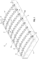
Fig. 1 is a perspective view of a furniture frame and sinuous springs extending from one side to the other side of the frame, clip assemblies in accordance with one embodiment being secured to the frame sides; -
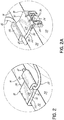
Fig. 2 is an enlarged view of the encircled area 2 ofFig. 1 ; -
Fig. 2A is an enlarged view of theencircled area 2A ofFig. 1 ; -
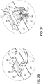
Fig. 2B is an enlarged view like the encircled area 2 showing pieces of connector secured to the clip assembly; -
Fig. 2C is an enlarged view like theencircled area 2A showing pieces of connector secured to the clip assembly; -
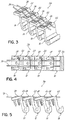
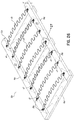
Fig. 3 is a perspective view of a portion of a collated string of clip assemblies ofFig. 1 ; -
Fig. 4 is a top plan view of the portion of the collated string of clip assemblies ofFig. 3 ; -
Fig. 5 is a side elevational view of the portion of the collated string of clip assemblies ofFig. 3 ; -
Fig. 6 is a partially disassembled view of a portion of the clip assembly ofFigs. 2B and 2C ; -
Fig. 6A is a partially disassembled view, similar toFig. 6 , of a portion of an alternative embodiment of clip assembly; -
Fig. 6B is a partially disassembled view, similar toFig. 6 , of a portion of an alternative embodiment of clip assembly; -
Fig. 7 is a top plan view of the clip assembly ofFig. 6 ; -
Fig. 8 is a side elevational view of the clip assembly ofFig. 6 ; -
Fig. 9 is a perspective view of a bag or collection of clip assemblies; -
Fig. 10 is a perspective view of a frame and sinuous springs extending from one side to the other side of the frame, clip assemblies in accordance with another embodiment being secured to the frame sides, similar toFig. 1 ; -
Fig. 11 is an enlarged view of theencircled area 11 ofFig. 10 ; -
Fig. 11A is an enlarged view, similar toFig. 11 , of the clip assembly ofFig. 11 showing a piece of connector secured to the clip assembly; -
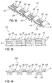
Fig. 12 is a perspective view of a portion of a collated string of clip assemblies ofFig. 10 ; -
Fig. 13 is a top plan view of the portion of the collated string of clip assemblies ofFig. 12 ; -
Fig. 14 is a side elevational view of the portion of the collated string of clip assemblies ofFig. 12 ; -
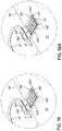
Fig. 15 is a partially disassembled view of a portion of the clip assembly ofFig. 11 ; -
Fig. 15A is a partially disassembled view, similar toFig. 15 , of a portion of an alternative embodiment of clip assembly; -
Fig. 16 is a top plan view of the clip assembly ofFig. 15 ; -
Fig. 17 is a side elevational view of the clip assembly ofFig. 15 ; -
Fig. 18 is a perspective view of a furniture frame and sinuous springs extending from one side to the other side of the frame, clip assemblies in accordance with another embodiment being secured to the frame sides, similar toFig. 10 ; -
Fig. 19 is an enlarged view of the encircled area 19 ofFig. 18 ; -
Fig. 19A is an enlarged view, similar toFig. 19 , of the clip assembly ofFig. 19 showing a piece of connector secured to the clip assembly; -
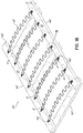
Fig. 20 is a perspective view of a portion of a collated string of clip assemblies ofFig. 18 ; -
Fig. 21 is a top plan view of the portion of the collated string of clip assemblies ofFig. 20 ; -
Fig. 22 is a side elevational view of the portion of the collated string of clip assemblies ofFig. 20 ; -
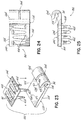
Fig. 23 is a partially disassembled view of a portion of the clip assembly ofFig. 18 ; -
Fig. 24 is a top plan view of the clip assembly ofFig. 23 ; -
Fig. 25 is a side elevational view of the clip assembly ofFig. 23 ; -
Fig. 26 is a perspective view of a furniture frame and sinuous springs extending from one side to the other side of the frame, clip assemblies in accordance with another embodiment being secured to the frame sides, similar toFig. 18 ; -
Fig. 27 is an enlarged view of the encircledarea 27 ofFig. 26 ; -
Fig. 27A is an enlarged view, similar toFig. 27 , of the clip assembly ofFig. 26 showing pieces of connectors secured to the clip assembly; -
Fig. 28 is a perspective view of a portion of a collated string of clip assemblies ofFig. 26 ; -
Fig. 29 is a top plan view of the portion of the collated string of clip assemblies ofFig. 28 ; -
Fig. 30 is a side elevational view of the portion of the collated string of clip assemblies ofFig. 28 ; -
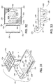
Fig. 31 is a partially disassembled view of a portion of the clip assembly ofFig. 28 ; -
Fig. 32 is a top plan view of the clip assembly ofFig. 28 ; and -
Fig. 33 is a side elevational view of the clip assembly ofFig. 28 . - Referring to the drawings, and particularly to
Fig. 1 , there is illustrated a portion of a piece of furniture 10 comprising a rectangular frame 12 comprising twoside walls 14 and two end walls 16 (only one being shown inFig. 1 ). For purposes of this document, the word "furniture" is not intended to be limiting; it may include seats for vehicles or other frames. The frame 12 is most commonly made of wood, but may be made of other suitable materials. In the embodiment of frame 12 shown inFig. 1 , each of the side and endwalls 14, 16, respectively, is placed on edge with the height "H" being greater than the width "W" of each wall. - As shown in
Fig. 1 , furniture piece 10 further comprises a plurality ofclip assemblies 18 secured to theside walls 14 of the frame 12 in a spaced manner for securing and retaining a plurality of sinuous springs 20.Clip assemblies 18, secured to opposedside walls 14, are aligned to receive and retainend portions 21 ofsinuous springs 20 in desired positions and under desired amounts of tension, as shown inFig. 1 . Commonly, suchsinuous springs 20 are arched or bowed upwardly to provide resiliency to the furniture piece 10. -
Figs. 2 and 2A each show one of theclip assemblies 18 secured to one of theside walls 14 of frame 12. As best shown inFig. 6 , eachclip assembly 18 comprises a first non-metallic piece orclip 22, usually made of plastic, and a second metal piece orfastener 24, respectively. Thepieces side walls 14 of the generally rectangular furniture frame 12. - The
first piece 22 ofclip assembly 18 comprises aU-shaped hook portion 26 adapted to receive and retain anend portion 21 of one of the sinuous springs 20. Thefirst piece 18 further comprises a generallyplanar body portion 28 which includes aledge 30 extending from oneside edge 32 to theopposed side edge 32 of thebody portion 28 of thefirst piece 22 of theclip assembly 18. When theend portion 21 of one of thesinuous springs 20 is inserted into theU-shaped hook portion 26, theledge 30 of thebody portion 28 holds or retains theend portion 21 of thesinuous spring 20 in areceptacle 31, illustrated inFig. 8 . Thefirst piece 22 ofclip assembly 18 further comprises a generallyplanar flange portion 34 extending outwardly from the end of thebody portion 28 opposite theU-shaped hook portion 26 in a direction generally orthogonal or perpendicular to thebody portion 28. As best shown inFig. 2A , theflange portion 34 of thefirst piece 22 ofclip assembly 18 has a pair of spacedgrooves 36 adapted to receivenon-metallic connectors 38 which connectmultiple clip assemblies 18 together, as shown inFigs. 3-5 . In some embodiments, thegrooves 36 may be omitted. For example, clip assemblies shown inFig. 6 may lackgrooves 36. - As shown in
Fig. 6 , theflange portion 34 of thefirst piece 22 ofclip assembly 18 has a pair of spacedopenings 40, each opening 40 extending through the thickness of theflange portion 34 of thefirst piece 22 ofclip assembly 18. Although theopenings 40 are shown as being round holes, they may be any other shapes, such as rectangular, for example. - As best shown in
Fig. 6 , thesecond piece 24 ofclip assembly 18 has a pair oftacks 42 extending downwardly from a generally planar, generallyU-shaped body portion 44 of thesecond piece 24 ofclip assembly 18. More particularly, each of thetacks 42 extends downwardly from one of thesides 45 of the generallyU-shaped body portion 44 of thesecond piece 24 ofclip assembly 18. Thesides 45 of the generallyU-shaped body portion 44 of thesecond piece 24 ofclip assembly 18 are connected by a connecting portion 47. Thetacks 42 of thesecond piece 24 ofclip assembly 18 are located and sized to pass through theopenings 40 of thefirst piece 22 ofclip assembly 18. Each of thetacks 42 of thesecond piece 24 ofclip assembly 18 has acrease 46 therein so thetack 42 has a non-planar cross-section. More particularly, the cross-section of eachtack 42 has a generally "V-shape", as shown inFig. 5 . As best shown inFig. 8 , each of thetacks 42 of thesecond piece 24 ofclip assembly 18 also has a plurality of vertically spaced serrations orindentations 48 to improve the holding strength of theclip assembly 18 to the wooden furniture frame 12. -
Fig. 6A illustrates an alternative clip assembly 18a having afirst piece 22 identical to the one shown inFig. 6 and a second piece 24a in which the tacks 24a are generally planar, lacking the crease andserrations 48 of each of thetacks 24 of thesecond piece 24 ofclip assembly 18 shown inFig. 6 . As shown inFig. 6A , each of thetacks 42a of second piece 24a of clip assembly 18a lacks thecrease 46 andserrations 48 of each of thetacks 24 of thesecond piece 24 ofclip assembly 18 shown inFig. 6 . -
Fig. 6B illustrates analternative clip assembly 18b having afirst piece 22b slightly different than thefirst piece 22 shown inFig. 6 and asecond piece 24 identical to thesecond piece 24 ofclip assembly 18 shown inFig. 6 . As shown inFig. 6B ,first piece 22b ofclip assembly 18b lacks theopenings 40 of thefirst piece 22 ofclip assembly 18 shown inFig. 6 . Inclip assembly 18b, thetacks 42 of thesecond piece 24 ofclip assembly 18b may be driven through the material of thefirst piece 22b ofclip assembly 18b. Alternatively, tacks liketacks 42a of the second piece 24a of clip assembly 18a may be used with a second piece of a clip assembly having no openings, in which case, the tacks would be driven through the material of the first piece of the clip assembly. In any of the embodiments described or illustrated herein, the plastic or non-metallic piece of the clip assembly may lack openings and the tacks of the metallic piece driven through the material of the plastic or non-metallic piece in order to secure the pieces of the clip assembly together. - As best illustrated in
Figs. 1 ,2 and 2A , thetacks 42 of thesecond piece 24 ofclip assembly 18 are secured inside one of theside walls 14 of furniture frame 12 with either an automated/mechanical machine or hand-held tool. When secured in place, theflange portion 34 of thefirst piece 22 ofclip assembly 18 contacts or abuts anouter side surface 50 of one of theside walls 14 of furniture frame 12, and thebody portion 28 of thefirst piece 22 ofclip assembly 18 contacts or abuts anupper end surface 52 of one of theside walls 14 of furniture frame 12. As best shown inFig. 2 , theU-shaped hook portion 26 of thefirst piece 22 ofclip assembly 18 is located generally above theinside side surface 54 of one of theside walls 14 of furniture frame 12. -
Fig. 3 shows fourclip assemblies 18 aligned in a similar orientation and having theflange portion 34 of thefirst piece 22 ofclip assembly 18 contacting or proximate thebody portion 28 of thefirst piece 22 of anadjacent clip assembly 18. When the clip assemblies are juxtaposed in such a manner, thegrooves 36 of eachclip assembly 18 are co-linearly aligned to permit aflexible connector 38 to be inserted into each of the alignedgrooves 36 and extend the length of the alignedclip assemblies 18. As best shown inFigs. 3-5 , the twoflexible connectors 38 are trapped or sandwiched between the first andsecond pieces clip assembly 18, each flexible connector being inside a plurality of alignedgrooves 36 ofmultiple clip assemblies 18. - Although
Figs. 3-5 show fourclip assemblies 18 aligned in astring 56 of aligned collatedclip assemblies 18, thestring 56 of aligned collatedclip assemblies 18 may be made of any number ofclip assemblies 18 connected together. In each of the aligned collatedclip assemblies 18, theconnectors 38 are trapped between the first andsecond pieces clip assembly 18. - The
connectors 38 used to interconnect adjacent alignedclip assemblies 38 into astring 56 are preferably fabricated from a plastic material, such as a low density polyethylene or polyester plastic. Theconnectors 38 provide a flexibility in the collatedstring 56 ofclip assemblies 18, which is needed when thestring 56 is bent and rolled into a spool for insertion into a clinching tool. Theconnectors 38 have the required tensile strength to withstand pulling and twisting forces without breaking. Also, when a last clip assembly is cut off from thestring 56, there are no sharp or jagged barbs left over to injure workers or tear fabric covering the clipped wires. - When used in a clipping tool, the
connectors 38 may be broken betweenadjacent clip assemblies 18 in the collatedstring 56 ofclip assemblies 18, leavingportions 58 of theconnectors 38 with theclip assembly 18 secured to the frame 12.Figs. 2B and 2C illustrate twosuch clip assemblies 18, eachclip assembly 18 havingportions 58 of theconnectors 38 still with theclip assembly 18 when theclip assembly 18 is secured to one of theside walls 14 of frame 12. -
Fig. 9 illustrates apackage 60 ofclip assemblies 18, which may be used to securesinuous springs 20 to a frame 12, as described herein. However, in this embodiment ofclip assembly 18, the secondmetallic piece 24 may or may not have any grooves. If theclip assemblies 18 lack the grooves, a plurality ofsuch clip assemblies 18 may not be connected withflexible connectors 38, likeclip assemblies 18. Therefore, theclip assemblies 18 may not be connected to each other and may be sold in apackage 60 of individual clip assemblies. -
Fig. 10 illustrates a portion of a piece of furniture 10b comprising arectangular frame 12b comprising twoside walls 14b and two end walls 16b (only one being shown inFig. 10 ). Theframe 12b is most commonly made of wood, but may be made of other suitable materials. In the embodiment offrame 12b shown inFig. 10 , each of the side and endwalls 14b, 16b, respectively, is oriented such that the width "W" of eachwall 14b, 16b is greater than its height "H". - As shown in
Fig. 10 , furniture piece 10b further comprises a plurality ofclip assemblies 18b secured to theside walls 14b of theframe 12b in a spaced manner for securing and retaining a plurality of sinuous springs 20.Clip assemblies 18b, secured to opposedside walls 14b, are aligned to receive and retainend portions 21 ofsinuous springs 20 in desired positions and under desired amounts of tension, as shown inFig. 10 . Commonly, suchsinuous springs 20 are arched or bowed upwardly to provide resiliency to the furniture piece 10. -
Figs. 11 and 11A each show one of theclip assemblies 18b secured to one of theside walls 14b offrame 12b. As best shown inFig. 15 , eachclip assembly 18b comprises a firstnon-metallic piece 22b, usually made of plastic, and asecond metal piece 24b, respectively. Thepieces side walls 14b of the generallyrectangular furniture frame 12b. - As best shown in
Fig. 15 , thefirst piece 22b ofclip assembly 18b comprises aU-shaped hook portion 26b adapted to receive and retain anend portion 21 of one of the sinuous springs 20. Thefirst piece 22b ofclip assembly 18b further comprises a generally planar body portion 28b, which includes aledge 30b extending from oneside edge 32b to theopposed side edge 32b of the body portion 28b of thefirst piece 22b of theclip assembly 18b. When theend portion 21 of one of thesinuous springs 20 is inserted into theU-shaped hook portion 26b, theledge 30b of the body portion 28b holds or retains theend portion 21 of thesinuous spring 20 in areceptacle 31b, illustrated inFig. 17 . As best shown inFig. 15A , the body portion 28b of thefirst piece 22b ofclip assembly 18b has a pair of spacedgrooves 36b along the outer periphery of the body portion 16b, each of thegrooves 36b being adapted to receive anon-metallic connector 38. Twoconnectors 38 connectmultiple clip assemblies 18b together, as shown inFigs. 12-14 . - As shown in
Fig. 15 , the body portion 28b of thefirst piece 22b ofclip assembly 18b has fouropenings 40b, eachopening 40b extending through the thickness of the body portion 28b of thefirst piece 22b ofclip assembly 18b. As best shown inFig. 15 , thesecond piece 24b ofclip assembly 18b has fourtacks 42b extending downwardly from a generally planar, generallybody portion 44b of thesecond piece 24b ofclip assembly 18b. More particularly, each of thetacks 42b is formed from material from thebody portion 44b of thesecond piece 24b ofclip assembly 18b using a punch press. Thetacks 24b initially lie in the plane of thebody portion 44b and are bent downwardly out of the plane, thereby leaving fouropenings 62 in thebody portion 44b of thesecond piece 24b ofclip assembly 18b. Thetacks 42b of thesecond piece 24b ofclip assembly 18b are located and sized to pass through theopenings 40b of thefirst piece 22b ofclip assembly 18b. Each of thetacks 42b of thesecond piece 24b of clip assembly 12 is generally planar, lacking the crease and serrations of the tacks 42c of the second piece 24c of clip assembly 18c, shown inFig. 15A . -
Fig. 15A illustrates an alternative clip assembly 18c having afirst piece 22b identical to the one shown inFig. 15 and a second piece 24c in which the tacks 42c has acrease 46 therein so the tack 42c has a non-planar cross-section. More particularly, the cross-section of each tack 42c has a generally "V-shape", as shown inFig. 15A . As best shown inFig. 15A , each of the tacks 42c of the second piece 24c of clip assembly 18c also has a plurality of serrations orindentations 48 to improve the holding strength of the clip assembly 18c to the wooden furniture frame. - As best illustrated in
Figs. 10 ,11 and 11A , thetacks 42b of thesecond piece 24b ofclip assembly 18b are secured inside one of theside walls 14b offurniture frame 12b with a clipping tool (not shown). When secured in place, the body portion 28b of thefirst piece 22b ofclip assembly 18b contacts or abuts anupper side surface 50 of one of theside walls 14b offurniture frame 12b. As best shown inFigs. 11 and 11b , theU-shaped hook portion 26b of thefirst piece 22b ofclip assembly 18b is located generally towards the interior of therectangular frame 12b. -
Fig. 12 shows fourclip assemblies 18b aligned in a similar orientation and having the body portion 28b of thefirst piece 22b of aclip assembly 18b contacting or proximate theU-shaped hook portion 26b of thefirst piece 22b of anadjacent clip assembly 18b. When theclip assemblies 18b are juxtaposed in such a manner, thegrooves 36b of eachclip assembly 18b are co-linearly aligned to permit aflexible connector 38 to be inserted into each of the alignedgrooves 36b and extend the length of the alignedclip assemblies 18b. As best shown inFigs. 12-14 , the twoflexible connectors 38 are trapped or sandwiched between the first andsecond pieces clip assembly 18b, eachflexible connector 38 being inside a plurality of alignedgrooves 36b ofmultiple clip assemblies 18b. - Although
Figs. 12-14 show fourclip assemblies 18b aligned in a string 56b of aligned collatedclip assemblies 18b, the string 56b of aligned collatedclip assemblies 18b may be made of any number ofclip assemblies 18b connected together. - The
connectors 38 used to interconnect adjacent alignedclip assemblies 18b into a string 56b are preferably fabricated from a plastic material, such as a low density polyethylene or polyester plastic. Theconnectors 38 provide a flexibility in the collated string 56b ofclip assemblies 18b, which is needed when the string 56b is bent and rolled into a spool for insertion into a clipping tool. Theconnectors 38 have the required tensile strength to withstand pulling and twisting forces without breaking. Also, when a last clip assembly is cut off from the string 56b, there are no sharp or jagged barbs left over to injure workers or tear fabric covering the clipped wires. - When used in a clipping tool, the
connectors 38 may be broken betweenadjacent clip assemblies 18b in the collated string 56b ofclip assemblies 18b, leavingportions 58 of theconnectors 38 with theclip assembly 18b secured to theframe 12b.Fig. 11A illustrates onesuch clip assembly 18b, eachclip assembly 18b having portions 58 of theconnectors 38 still with theclip assembly 18b when theclip assembly 18b is secured to one of theside walls 14b offrame 12b. -
Fig. 18 illustrates a portion of a piece of furniture 10d comprising a rectangular frame 12d comprising twoside walls 14d and twoend walls 16d (only one being shown inFig. 18 ). The frame 12d is most commonly made of wood, but may be made of other suitable materials. In the embodiment of frame 12d shown inFig. 18 , each of the side and endwalls wall - As shown in
Fig. 18 , furniture piece 10d further comprises a plurality ofclip assemblies 18d secured to theside walls 14d of the frame 12d in a spaced manner for securing and retaining a plurality of sinuous springs 20.Clip assemblies 18d, secured to opposedside walls 14d, are aligned to receive and retainend portions 21 ofsinuous springs 20 in desired positions and under a desired amount of tension, as shown inFig. 18 . Commonly, suchsinuous springs 20 are arched or bowed upwardly to provide resiliency to the furniture piece 10d. -
Figs. 19 and 19A each show one of theclip assemblies 18d secured to one of theside walls 14b offrame 12b. As best shown inFig. 23 , eachclip assembly 18d comprises a firstnon-metallic piece 22d, usually made of plastic, and asecond metal piece 24d, respectively. Thepieces side walls 14d of the generally rectangular furniture frame 12d. - As shown in
Fig. 23 , thefirst piece 22d ofclip assembly 18d comprises aU-shaped hook portion 26d adapted to receive and retain anend portion 21 of one of the sinuous springs 20. Thefirst piece 22d ofclip assembly 18d further comprises a generallyplanar body portion 28d, which includes aledge 30d extending from oneside edge 32d to theopposed side edge 32d of thebody portion 28d of thefirst piece 22d of theclip assembly 18d. When theend portion 21 of one of thesinuous springs 20 is inserted into theU-shaped hook portion 26d, theledge 30d of thebody portion 28d holds or retains theend portion 21 of thesinuous spring 20 in areceptacle 31d, illustrated inFig. 25 . As best shown inFig. 23 , theU-shaped hook portion 26d of thefirst piece 22d ofclip assembly 18d has agroove 36d extending inwardly from the outer surface of theU-shaped hook portion 26d, thegroove 36d being adapted to receive anon-metallic connector 38. Oneconnector 38 connectsmultiple clip assemblies 18d together, as shown inFigs. 20-22 . - As shown in
Fig. 23 , thebody portion 28d of thefirst piece 22d ofclip assembly 18d has fouropenings 40d, eachopening 40d extending through the thickness of thebody portion 28d of thefirst piece 22d ofclip assembly 18d. As best shown inFig. 23 , thesecond piece 24d ofclip assembly 18d has four tacks 42d extending downwardly from a generally planar, generallybody portion 44d of thesecond piece 24d ofclip assembly 18d. More particularly, each of the tacks 42d is formed from material from thebody portion 44d of thesecond piece 24d ofclip assembly 18d using a punch press. Thetacks 24d initially lie in the plane of thebody portion 44d and are bent downwardly out of the plane, thereby leaving fouropenings 62 in thebody portion 44d of thesecond piece 24d ofclip assembly 18d. The tacks 42d of thesecond piece 24d ofclip assembly 18b are located and sized to pass through theopenings 40d of thefirst piece 22d ofclip assembly 18d. Each of the tacks 42d of thesecond piece 24d of clip assembly 12 are generally planar, lacking the crease and serrations of the tacks 42c of the second piece 24c of clip assembly 18c, shown inFig. 15A . However, the tacks 42d of thesecond piece 24d ofclip assembly 18d may have creases or serrations, as illustrated and described herein. - As best illustrated in
Figs. 18 ,19 and 19A , the tacks 42d of thesecond piece 24d ofclip assembly 18d are secured inside one of theside walls 14d of furniture frame 12d with a clipping tool (not shown). When secured in place, thebody portion 28d of thefirst piece 22d ofclip assembly 18d contacts or abuts anupper side surface 50 of one of theside walls 14d of furniture frame 12d. As best shown inFigs. 19 and 19A , theU-shaped hook portion 26d of thefirst piece 22d ofclip assembly 18d is located generally towards the interior of the rectangular frame 12d. -
Fig. 20 shows fourclip assemblies 18d aligned in a similar orientation and having thebody portion 28d of thefirst piece 22d of aclip assembly 18d contacting or proximate theU-shaped hook portion 26d of thefirst piece 22d of anadjacent clip assembly 18d. When theclip assemblies 18d are juxtaposed in such a manner, thegroove 36d of eachclip assembly 18b is co-linearly aligned to permit aflexible connector 38 to be inserted into the alignedgrooves 36d and extend the length of the alignedclip assemblies 18d. As best shown inFigs. 20-22 , theflexible connector 38 is trapped or sandwiched between the first andsecond pieces clip assembly 18d, eachflexible connector 38 being inside a plurality of alignedgrooves 36d ofmultiple clip assemblies 18d. - Although
Figs. 20-22 show fourclip assemblies 18d aligned in astring 56d of aligned collatedclip assemblies 18d, thestring 56d of aligned collatedclip assemblies 18d may be made of any number ofclip assemblies 18d connected together. - The
connector 38 used to interconnect adjacent alignedclip assemblies 18d into astring 56d is preferably fabricated from a plastic material, such as a low density polyethylene or polyester plastic. Theconnector 38 provides a flexibility in the collatedstring 56d ofclip assemblies 18d, which is needed when thestring 56d is bent and rolled into a spool for insertion into a clipping tool. Theconnector 38 has the required tensile strength to withstand pulling and twisting forces without breaking. Also, when a last clip assembly is cut off from thestring 56d, there are no sharp or jagged barbs left over to injure workers or tear fabric covering the clipped wires. - When used in a clipping tool, the
connector 38 may be broken betweenadjacent clip assemblies 18d in the collatedstring 56d ofclip assemblies 18d, leavingportions 58 of theconnector 38 with theclip assembly 18d secured to the frame 12d.Fig. 19A illustrates onesuch clip assembly 18d, eachclip assembly 18d having portions 58 of theconnector 38 still with theclip assembly 18d when theclip assembly 18d is secured to one of theside walls 14d of frame 12d. -
Fig. 26 illustrates a portion of a piece offurniture 10e comprising a rectangular frame 12e comprising twoside walls 14e and twoend walls 16e (only one being shown inFig. 26 ). The frame 12e is most commonly made of wood, but may be made of other suitable materials. In the embodiment of frame 12e shown inFig. 26 , each of the side and endwalls wall - As shown in
Fig. 26 ,furniture piece 10e further comprises a plurality ofclip assemblies 18e secured to theside walls 14e of the frame 12e in a spaced manner for securing and retaining a plurality of sinuous springs 20.Clip assemblies 18e, secured to opposedside walls 14e, are aligned to receive and retain anend portion 21 of asinuous spring 20 in a desired position and under a desired amount of tension, as shown inFig. 26 . Commonly, suchsinuous springs 20 are arched or bowed upwardly to provide resiliency to thefurniture piece 10e. -
Figs. 27 and 27A each show one of theclip assemblies 18e secured to one of theside walls 14e of frame 12e. As best shown inFig. 31 , eachclip assembly 18e comprises a firstnon-metallic piece 22e, usually made of plastic, and asecond metal piece 24e, respectively. Thepieces side walls 14e of the generally rectangular furniture frame 12e. - The
first piece 22e ofclip assembly 18e comprises aU-shaped hook portion 26e adapted to receive and retain anend portion 21 of one of thesinuous springs 20 having anend ledge 64. Thefirst piece 22e ofclip assembly 18e further comprises a generally planar body portion 28e, which includes astop 66 extending from oneside edge 32e to theopposed side edge 32e of the body portion 28e of thefirst piece 22e of theclip assembly 18e. When theend portion 21 of one of thesinuous springs 20 is inserted into theU-shaped hook portion 26e, thestop 66 of the body portion 28e abuts the frame 12e, as shown inFig. 27 . TheU-shaped hook portion 26e holds or retains theend portion 21 of thesinuous spring 20 in a receptacle 31e, illustrated inFig. 27 . As best shown inFig. 27A , the body portion 28e of thefirst piece 22e ofclip assembly 18e has a pair of spacedgrooves 36e along the outer periphery of the body portion 28e, each of thegrooves 36e being adapted to receive anon-metallic connector 38. Twoconnectors 38 connectmultiple clip assemblies 18e together, as shown inFigs. 28-30 . - As shown in
Fig. 27 , the body portion 28e of thefirst piece 22e ofclip assembly 18e has fouropenings 40e, eachopening 40e extending through the thickness of the body portion 28e of thefirst piece 22e ofclip assembly 18e. As best shown inFig. 27 , thesecond piece 24e ofclip assembly 18e has fourtacks 42e extending downwardly from a generally planar, generallybody portion 44e of thesecond piece 24e ofclip assembly 18e. More particularly, each of thetacks 42e is formed from material from thebody portion 44e of thesecond piece 24e ofclip assembly 18e, using a punch press. Thetacks 24e initially lie in the plane of thebody portion 44e and are bent downwardly out of the plane, thereby leaving fouropenings 62 in thebody portion 44e of thesecond piece 24e ofclip assembly 18e. Thetacks 42e of thesecond piece 24e ofclip assembly 18e are located and sized to pass through theopenings 40e of thefirst piece 22e ofclip assembly 18e. Each of thetacks 42e of thesecond piece 24e of clip assembly 12 is generally planar, lacking the crease of the tacks 42c of the second piece 24c of clip assembly 18c shown inFig. 15A . However, thetacks 42e of thesecond piece 24e ofclip assembly 18e may have creases or serrations, as illustrated and described herein. - As best illustrated in
Figs. 26 ,27 and 27A , thetacks 42e of thesecond piece 24e ofclip assembly 18e are secured inside one of theside walls 14e of furniture frame 12e with a clipping tool (not shown). When secured in place, the body portion 28e of thefirst piece 22e ofclip assembly 18e contacts or abuts anupper side surface 50 of one of theside walls 14e of furniture frame 12e. As best shown inFigs. 27 and 27A , theU-shaped hook portion 26e of thefirst piece 22e ofclip assembly 18e is located generally towards the interior of the rectangular frame 12e. -
Fig. 28 shows fourclip assemblies 18e aligned in a similar orientation and having the body portion 28e of thefirst piece 22e of aclip assembly 18e contacting or proximate theU-shaped hook portion 26e of thefirst piece 22e of anadjacent clip assembly 18e. When theclip assemblies 18e are juxtaposed in such a manner, thegrooves 36e of eachclip assembly 18e are co-linearly aligned to permit aflexible connector 38 to be inserted into each of the alignedgrooves 36 and extend the length of the alignedclip assemblies 18e. As best shown inFigs. 28-30 , the twoflexible connectors 38 are trapped or sandwiched between the first andsecond pieces clip assembly 18e, eachflexible connector 38 being inside a plurality of alignedgrooves 36e ofmultiple clip assemblies 18e. - Although
Figs. 28-30 show fourclip assemblies 18e aligned in astring 56e of aligned collatedclip assemblies 18e, thestring 56e of aligned collatedclip assemblies 18e may be made of any number ofclip assemblies 18e connected together. - The
connectors 38 used to interconnect adjacent alignedclip assemblies 18e into astring 56e are preferably fabricated from a plastic material, such as a low density polyethylene or polyester plastic. Theconnectors 38 provide a flexibility in the collatedstring 56e ofclip assemblies 18e, which is needed when thestring 56e is bent and rolled into a spool for insertion into a clipping tool. Theconnectors 38 have the required tensile strength to withstand pulling and twisting forces without breaking. Also, when a last clip assembly is cut off from thestring 56e, there are no sharp or jagged barbs left over to injure workers or tear fabric covering the clipped wires. - When used in a clipping tool, the
connectors 38 may be broken betweenadjacent clip assemblies 18e in the collatedstring 56e ofclip assemblies 18e, leavingportions 58 of theconnectors 38 with theclip assembly 18e secured to the frame 12e.Fig. 27A illustrates onesuch clip assembly 18e, eachclip assembly 18e having portions 58 of theconnectors 38 still with theclip assembly 18e when theclip assembly 18e is secured to one of theside walls 14e of frame 12e. - Although the tacks are shown having a certain cross-sectional configuration, they may be other sizes or shapes. Similarly, the openings in the non-metallic pieces of the clip assemblies may be any desired shapes or sizes. Although we have described several embodiments of the invention, we do not intend to be limited except by the scope of the following claims. For example, the headboard may be omitted.
Claims (12)
- A clip assembly (18b-18e) for securing an end portion (21) of a sinuous spring (20) to a wooden rail (14b-14e), said clip assembly (18b-18e) comprising:a non-metallic clip (22b-22e) having a generally planar body portion (28b-28e) and a U-shaped hook portion (26b-26e), the body portion (28b-28e) having spaced grooves (36b-36e) adapted to receive flexible connectors (38) to join multiple clip assemblies (18b-18e) together;a metal fastener (24b-24e) including multiple tacks (42b-42e) extending outwardly from a generally planar portion of the fastener (24b-24e), wherein each of the tacks (42b-42e) passes through a preexisting opening (40b-40e) in the body portion (28b-28e) of the non-metallic clip (22b-22e); andportions of flexible connectors (38) being inside the spaced grooves (36b-36e) of the non-metallic clip (22b-22e) and sandwiched between the non-metallic clip (22b-22e) and the metal fastener (24e-24e) of the clip assembly (18b-18e).
- The clip assembly (18b-18e) of claim 1 wherein the generally planar body portion (28b-28e) of the non-metallic clip (22b-22e) has a ledge (30b) extending from one side edge (32b) to the opposite side edge (32b) of the body portion (28b-28e).
- The clip assembly (18b-18e) of claim 1 or claim 2 wherein the metal fastener (24b-24e) is a unitary member, the tacks (42b-42e) of the metal fastener (24b-24e) being formed from the material of the metal fastener (24b-24e) and extending outwardly from the remainder of the metal fastener (24b-24e).
- The clip assembly (18b-18e) of any one of claims 1-3 wherein at least one of the tacks (42b-42e) of the metal fastener (24b-24e) is serrated.
- The clip assembly (18b-18e) of any one of claims 1-4 wherein each of the tacks (42b-42e) of the metal fastener (24b-24e) is serrated.
- The clip assembly (18b-18e) of any one of claims 1-5 wherein the metal fastener (24b-24e) has four tacks (42b-42e).
- The clip assembly (18b-18e) of any one of claims 1-6 wherein at least one of the tacks (42b-42e) of the metal fastener (24b-24e) is creased.
- The clip assembly (18b-18e) of any one of claims 1-7 wherein each of the tacks (42b-42e) of the metal fastener (24b-24e) is creased.
- The clip assembly (18b-18e) of any one of claims 1-8 wherein the flexible connectors (38) are made of plastic.
- The clip assembly (18b-18e) of any one of claims 1-9 wherein the spaced grooves (36b-36e) are located adjacent side edges of the generally planar body portion (28b-28e) of the non-metallic clip (22b-22e).
- The clip assembly (18b-18e) of any one of claims 1-10 wherein the non-metallic clip (22b-22e) is a plastic clip.
- The clip assembly (18b-18e) of any one of claims 1-11 wherein the metal fastener (24b-24e) has openings created by forming the tacks (42b-42e).
Priority Applications (1)
| Application Number | Priority Date | Filing Date | Title |
|---|---|---|---|
| PL17157123T PL3187073T3 (en) | 2012-10-10 | 2013-10-01 | Clip assembly for use holding sinuous springs |
Applications Claiming Priority (2)
| Application Number | Priority Date | Filing Date | Title |
|---|---|---|---|
| US13/648,611 US8991016B2 (en) | 2012-10-10 | 2012-10-10 | Clip assembly for use holding sinuous springs |
| EP13844978.0A EP2906082B1 (en) | 2012-10-10 | 2013-10-01 | Clip assembly for use holding sinuous springs |
Related Parent Applications (2)
| Application Number | Title | Priority Date | Filing Date |
|---|---|---|---|
| EP13844978.0A Division-Into EP2906082B1 (en) | 2012-10-10 | 2013-10-01 | Clip assembly for use holding sinuous springs |
| EP13844978.0A Division EP2906082B1 (en) | 2012-10-10 | 2013-10-01 | Clip assembly for use holding sinuous springs |
Publications (2)
| Publication Number | Publication Date |
|---|---|
| EP3187073A1 true EP3187073A1 (en) | 2017-07-05 |
| EP3187073B1 EP3187073B1 (en) | 2018-04-25 |
Family
ID=50431579
Family Applications (2)
| Application Number | Title | Priority Date | Filing Date |
|---|---|---|---|
| EP17157123.5A Not-in-force EP3187073B1 (en) | 2012-10-10 | 2013-10-01 | Clip assembly for use holding sinuous springs |
| EP13844978.0A Not-in-force EP2906082B1 (en) | 2012-10-10 | 2013-10-01 | Clip assembly for use holding sinuous springs |
Family Applications After (1)
| Application Number | Title | Priority Date | Filing Date |
|---|---|---|---|
| EP13844978.0A Not-in-force EP2906082B1 (en) | 2012-10-10 | 2013-10-01 | Clip assembly for use holding sinuous springs |
Country Status (7)
| Country | Link |
|---|---|
| US (2) | US8991016B2 (en) |
| EP (2) | EP3187073B1 (en) |
| CN (2) | CN107252214B (en) |
| BR (1) | BR112015007895B1 (en) |
| MX (1) | MX356928B (en) |
| PL (2) | PL3187073T3 (en) |
| WO (1) | WO2014058661A1 (en) |
Families Citing this family (12)
| Publication number | Priority date | Publication date | Assignee | Title |
|---|---|---|---|---|
| US9777758B2 (en) | 2012-10-10 | 2017-10-03 | L&P Property Management Company | Clip assembly for use holding sinuous springs |
| US9427094B2 (en) | 2012-10-10 | 2016-08-30 | L&P Property Management Company | Clip assembly for use holding sinuous springs |
| US8991016B2 (en) | 2012-10-10 | 2015-03-31 | L&P Property Management Company | Clip assembly for use holding sinuous springs |
| BR112017000561A2 (en) * | 2014-09-30 | 2018-01-23 | L&P Property Man Co | clamp units for use in winding spring retention |
| US9933000B2 (en) * | 2015-06-19 | 2018-04-03 | L&P Property Management Company | Clip assembly for use holding sinuous springs |
| CN105167459A (en) * | 2015-08-19 | 2015-12-23 | 张家港市恒科新材料有限公司 | Novel snap hook for sofa |
| US10512338B1 (en) * | 2017-06-01 | 2019-12-24 | Ashley Furniture Industries, Inc. | Furniture assembly with metal seat stretcher |
| CN107692647A (en) * | 2017-10-27 | 2018-02-16 | 黎湛权 | A kind of reliable bedstead of stabilized structure |
| RU183252U1 (en) * | 2017-11-02 | 2018-09-14 | Минасянц Нерсес Давидович | Mattress holder for the mattress |
| LT3586682T (en) | 2018-06-25 | 2021-01-25 | Starsprings Ab | STRENGTH ADJUSTMENT DEVICE USED IN BED OR SOFA CONSTRUCTION |
| NO346566B1 (en) * | 2020-04-28 | 2022-10-10 | H2 Norway As | Seating device with reclining function |
| CN118302086A (en) * | 2021-11-19 | 2024-07-05 | Ykk株式会社 | Clip component |
Citations (6)
| Publication number | Priority date | Publication date | Assignee | Title |
|---|---|---|---|---|
| US2574811A (en) | 1948-02-07 | 1951-11-13 | Universal Wire Spring Co | Portable clipping tool |
| US4935998A (en) * | 1989-06-22 | 1990-06-26 | Hartco Company | Fastener clip for furniture rails |
| US5303821A (en) | 1992-11-06 | 1994-04-19 | Ayres Donald B | Resilient clip assembly |
| US5564564A (en) | 1995-06-16 | 1996-10-15 | L&P Property Management Company | Collated clip assembly |
| US5833064A (en) | 1996-05-17 | 1998-11-10 | Vertex Fasteners | String of anchor clips |
| US5878880A (en) | 1995-06-16 | 1999-03-09 | L&P Property Management Company | Collated clip assembly |
Family Cites Families (28)
| Publication number | Priority date | Publication date | Assignee | Title |
|---|---|---|---|---|
| US3323183A (en) | 1967-06-06 | Upholstery spring attachment clip fok furniture | ||
| US2111404A (en) * | 1935-09-05 | 1938-03-15 | William G Pankonin | Staple |
| US2526902A (en) | 1947-07-31 | 1950-10-24 | Norman C Rublee | Insulating staple |
| DE1252125B (en) | 1961-06-08 | 1967-10-12 | Bostitch Inc East Greenwich, R I (V St A) | (V St A) I Belt-like arrangement of a row of nails |
| US3252569A (en) | 1963-01-29 | 1966-05-24 | Plasti Clad Metal Products Inc | Plastic coated laminated nail |
| US3263294A (en) | 1964-03-20 | 1966-08-02 | William J Pappas | Support |
| US3422468A (en) * | 1966-09-13 | 1969-01-21 | Lear Siegler Inc | Spring clip |
| US3553794A (en) | 1968-09-26 | 1971-01-12 | Stanley Works | Wireless strapping seal |
| US3613878A (en) | 1969-08-29 | 1971-10-19 | Hartco Co | U-clip assembly |
| US3722670A (en) | 1971-03-19 | 1973-03-27 | Signode Corp | Clip stack |
| US3711931A (en) | 1971-04-01 | 1973-01-23 | Multifastener Corp | Method of forming fastener strip |
| US3845860A (en) | 1971-04-01 | 1974-11-05 | Multifastener Corp | Fastener strip |
| CA971010A (en) | 1972-01-14 | 1975-07-15 | Signode Corporation | Nail strip and method of making same |
| US3940844A (en) | 1972-02-22 | 1976-03-02 | Pci Group, Inc. | Method of installing an insulating sleeve on a staple |
| US3874263A (en) * | 1972-02-29 | 1975-04-01 | Illinois Tool Works | Metal penetrating staple |
| US4129059A (en) | 1974-11-07 | 1978-12-12 | Eck William F Van | Staple-type fastener |
| US3992853A (en) * | 1975-06-09 | 1976-11-23 | Morris Max O | Spring clip |
| US4153959A (en) | 1976-07-14 | 1979-05-15 | Omley Industries, Inc. | Spring attachment clip |
| AU555489B2 (en) | 1982-04-09 | 1986-09-25 | Hartco Co. | U-clip assembly |
| US4955813A (en) | 1989-09-21 | 1990-09-11 | Fochler Stephen H | Multi-pronged thumbtack |
| USD330851S (en) | 1990-08-16 | 1992-11-10 | Roick Reinhard M | Furniture spring hook |
| US5314065A (en) | 1993-05-03 | 1994-05-24 | L&P Property Management Company | Sheet metal clip |
| US5927491A (en) | 1996-03-12 | 1999-07-27 | Stanley/Hartco Company | Resilient U-clip assembly |
| US6415481B1 (en) * | 1997-10-08 | 2002-07-09 | Stanley Fastening Systems, L.P. | Squeakless furniture spring anchor clip |
| US6126126A (en) | 1998-06-18 | 2000-10-03 | Mckiernan, Jr.; Robert D. | Tack with three prongs |
| CA2354502C (en) | 2001-07-31 | 2009-04-07 | Reinhard Roick | Spring anchor clip for seating and furniture frames |
| US7882948B2 (en) | 2008-03-07 | 2011-02-08 | West Robert J | U-clip assembly and method |
| US8991016B2 (en) | 2012-10-10 | 2015-03-31 | L&P Property Management Company | Clip assembly for use holding sinuous springs |
-
2012
- 2012-10-10 US US13/648,611 patent/US8991016B2/en active Active
-
2013
- 2013-10-01 PL PL17157123T patent/PL3187073T3/en unknown
- 2013-10-01 EP EP17157123.5A patent/EP3187073B1/en not_active Not-in-force
- 2013-10-01 CN CN201710563792.7A patent/CN107252214B/en not_active Expired - Fee Related
- 2013-10-01 BR BR112015007895-8A patent/BR112015007895B1/en not_active IP Right Cessation
- 2013-10-01 PL PL13844978T patent/PL2906082T3/en unknown
- 2013-10-01 MX MX2015004518A patent/MX356928B/en active IP Right Grant
- 2013-10-01 CN CN201380063155.3A patent/CN104869871B/en not_active Expired - Fee Related
- 2013-10-01 EP EP13844978.0A patent/EP2906082B1/en not_active Not-in-force
- 2013-10-01 WO PCT/US2013/062844 patent/WO2014058661A1/en not_active Ceased
-
2015
- 2015-02-23 US US14/628,579 patent/US9420897B2/en not_active Expired - Fee Related
Patent Citations (7)
| Publication number | Priority date | Publication date | Assignee | Title |
|---|---|---|---|---|
| US2574811A (en) | 1948-02-07 | 1951-11-13 | Universal Wire Spring Co | Portable clipping tool |
| US4935998A (en) * | 1989-06-22 | 1990-06-26 | Hartco Company | Fastener clip for furniture rails |
| US5303821A (en) | 1992-11-06 | 1994-04-19 | Ayres Donald B | Resilient clip assembly |
| US5564564A (en) | 1995-06-16 | 1996-10-15 | L&P Property Management Company | Collated clip assembly |
| US5682994A (en) | 1995-06-16 | 1997-11-04 | L&P Property Management Company | Collated clip assembly |
| US5878880A (en) | 1995-06-16 | 1999-03-09 | L&P Property Management Company | Collated clip assembly |
| US5833064A (en) | 1996-05-17 | 1998-11-10 | Vertex Fasteners | String of anchor clips |
Also Published As
| Publication number | Publication date |
|---|---|
| US20150164239A1 (en) | 2015-06-18 |
| EP2906082B1 (en) | 2017-04-19 |
| PL2906082T3 (en) | 2017-09-29 |
| US20140096346A1 (en) | 2014-04-10 |
| CN107252214A (en) | 2017-10-17 |
| US9420897B2 (en) | 2016-08-23 |
| EP2906082A1 (en) | 2015-08-19 |
| CN107252214B (en) | 2019-11-05 |
| CN104869871B (en) | 2017-07-11 |
| MX356928B (en) | 2018-06-19 |
| MX2015004518A (en) | 2015-07-14 |
| BR112015007895B1 (en) | 2020-09-24 |
| WO2014058661A1 (en) | 2014-04-17 |
| US8991016B2 (en) | 2015-03-31 |
| EP3187073B1 (en) | 2018-04-25 |
| CN104869871A (en) | 2015-08-26 |
| EP2906082A4 (en) | 2016-06-01 |
| PL3187073T3 (en) | 2018-09-28 |
Similar Documents
| Publication | Publication Date | Title |
|---|---|---|
| EP3187073B1 (en) | Clip assembly for use holding sinuous springs | |
| US9770116B2 (en) | Clip assembly for use holding sinuous springs | |
| US9933000B2 (en) | Clip assembly for use holding sinuous springs | |
| US5314065A (en) | Sheet metal clip | |
| EP0906226B1 (en) | String of anchor clips | |
| US9777758B2 (en) | Clip assembly for use holding sinuous springs | |
| AU673220B2 (en) | Resilient clip assembly | |
| US5927491A (en) | Resilient U-clip assembly | |
| US5564564A (en) | Collated clip assembly | |
| EP0897685B1 (en) | Picture hanger | |
| WO2016053709A1 (en) | Clip assembly for use holding sinuous springs | |
| US5314064A (en) | Sheet metal clip | |
| US5878880A (en) | Collated clip assembly | |
| WO2018026624A1 (en) | Clip assembly for use holding sinuous springs | |
| US876124A (en) | Metal structure. | |
| WO1997033816A1 (en) | Improved resilient u-clip assembly | |
| JP2021062239A (en) | Merchandise display store fixture |
Legal Events
| Date | Code | Title | Description |
|---|---|---|---|
| PUAI | Public reference made under article 153(3) epc to a published international application that has entered the european phase |
Free format text: ORIGINAL CODE: 0009012 |
|
| AC | Divisional application: reference to earlier application |
Ref document number: 2906082 Country of ref document: EP Kind code of ref document: P |
|
| AK | Designated contracting states |
Kind code of ref document: A1 Designated state(s): AL AT BE BG CH CY CZ DE DK EE ES FI FR GB GR HR HU IE IS IT LI LT LU LV MC MK MT NL NO PL PT RO RS SE SI SK SM TR |
|
| 17P | Request for examination filed |
Effective date: 20170619 |
|
| RBV | Designated contracting states (corrected) |
Designated state(s): AL AT BE BG CH CY CZ DE DK EE ES FI FR GB GR HR HU IE IS IT LI LT LU LV MC MK MT NL NO PL PT RO RS SE SI SK SM TR |
|
| 17Q | First examination report despatched |
Effective date: 20170816 |
|
| GRAP | Despatch of communication of intention to grant a patent |
Free format text: ORIGINAL CODE: EPIDOSNIGR1 |
|
| INTG | Intention to grant announced |
Effective date: 20171116 |
|
| GRAS | Grant fee paid |
Free format text: ORIGINAL CODE: EPIDOSNIGR3 |
|
| GRAA | (expected) grant |
Free format text: ORIGINAL CODE: 0009210 |
|
| AC | Divisional application: reference to earlier application |
Ref document number: 2906082 Country of ref document: EP Kind code of ref document: P |
|
| AK | Designated contracting states |
Kind code of ref document: B1 Designated state(s): AL AT BE BG CH CY CZ DE DK EE ES FI FR GB GR HR HU IE IS IT LI LT LU LV MC MK MT NL NO PL PT RO RS SE SI SK SM TR |
|
| REG | Reference to a national code |
Ref country code: GB Ref legal event code: FG4D |
|
| REG | Reference to a national code |
Ref country code: CH Ref legal event code: EP |
|
| REG | Reference to a national code |
Ref country code: AT Ref legal event code: REF Ref document number: 991926 Country of ref document: AT Kind code of ref document: T Effective date: 20180515 |
|
| REG | Reference to a national code |
Ref country code: IE Ref legal event code: FG4D |
|
| REG | Reference to a national code |
Ref country code: DE Ref legal event code: R096 Ref document number: 602013036739 Country of ref document: DE |
|
| REG | Reference to a national code |
Ref country code: NL Ref legal event code: MP Effective date: 20180425 |
|
| REG | Reference to a national code |
Ref country code: LT Ref legal event code: MG4D |
|
| PG25 | Lapsed in a contracting state [announced via postgrant information from national office to epo] |
Ref country code: NL Free format text: LAPSE BECAUSE OF FAILURE TO SUBMIT A TRANSLATION OF THE DESCRIPTION OR TO PAY THE FEE WITHIN THE PRESCRIBED TIME-LIMIT Effective date: 20180425 |
|
| PG25 | Lapsed in a contracting state [announced via postgrant information from national office to epo] |
Ref country code: NO Free format text: LAPSE BECAUSE OF FAILURE TO SUBMIT A TRANSLATION OF THE DESCRIPTION OR TO PAY THE FEE WITHIN THE PRESCRIBED TIME-LIMIT Effective date: 20180725 Ref country code: BG Free format text: LAPSE BECAUSE OF FAILURE TO SUBMIT A TRANSLATION OF THE DESCRIPTION OR TO PAY THE FEE WITHIN THE PRESCRIBED TIME-LIMIT Effective date: 20180725 Ref country code: SE Free format text: LAPSE BECAUSE OF FAILURE TO SUBMIT A TRANSLATION OF THE DESCRIPTION OR TO PAY THE FEE WITHIN THE PRESCRIBED TIME-LIMIT Effective date: 20180425 Ref country code: FI Free format text: LAPSE BECAUSE OF FAILURE TO SUBMIT A TRANSLATION OF THE DESCRIPTION OR TO PAY THE FEE WITHIN THE PRESCRIBED TIME-LIMIT Effective date: 20180425 Ref country code: ES Free format text: LAPSE BECAUSE OF FAILURE TO SUBMIT A TRANSLATION OF THE DESCRIPTION OR TO PAY THE FEE WITHIN THE PRESCRIBED TIME-LIMIT Effective date: 20180425 Ref country code: LT Free format text: LAPSE BECAUSE OF FAILURE TO SUBMIT A TRANSLATION OF THE DESCRIPTION OR TO PAY THE FEE WITHIN THE PRESCRIBED TIME-LIMIT Effective date: 20180425 |
|
| PG25 | Lapsed in a contracting state [announced via postgrant information from national office to epo] |
Ref country code: GR Free format text: LAPSE BECAUSE OF FAILURE TO SUBMIT A TRANSLATION OF THE DESCRIPTION OR TO PAY THE FEE WITHIN THE PRESCRIBED TIME-LIMIT Effective date: 20180726 Ref country code: LV Free format text: LAPSE BECAUSE OF FAILURE TO SUBMIT A TRANSLATION OF THE DESCRIPTION OR TO PAY THE FEE WITHIN THE PRESCRIBED TIME-LIMIT Effective date: 20180425 Ref country code: HR Free format text: LAPSE BECAUSE OF FAILURE TO SUBMIT A TRANSLATION OF THE DESCRIPTION OR TO PAY THE FEE WITHIN THE PRESCRIBED TIME-LIMIT Effective date: 20180425 Ref country code: RS Free format text: LAPSE BECAUSE OF FAILURE TO SUBMIT A TRANSLATION OF THE DESCRIPTION OR TO PAY THE FEE WITHIN THE PRESCRIBED TIME-LIMIT Effective date: 20180425 |
|
| REG | Reference to a national code |
Ref country code: AT Ref legal event code: MK05 Ref document number: 991926 Country of ref document: AT Kind code of ref document: T Effective date: 20180425 |
|
| PG25 | Lapsed in a contracting state [announced via postgrant information from national office to epo] |
Ref country code: PT Free format text: LAPSE BECAUSE OF FAILURE TO SUBMIT A TRANSLATION OF THE DESCRIPTION OR TO PAY THE FEE WITHIN THE PRESCRIBED TIME-LIMIT Effective date: 20180827 |
|
| REG | Reference to a national code |
Ref country code: DE Ref legal event code: R097 Ref document number: 602013036739 Country of ref document: DE |
|
| PG25 | Lapsed in a contracting state [announced via postgrant information from national office to epo] |
Ref country code: RO Free format text: LAPSE BECAUSE OF FAILURE TO SUBMIT A TRANSLATION OF THE DESCRIPTION OR TO PAY THE FEE WITHIN THE PRESCRIBED TIME-LIMIT Effective date: 20180425 Ref country code: AT Free format text: LAPSE BECAUSE OF FAILURE TO SUBMIT A TRANSLATION OF THE DESCRIPTION OR TO PAY THE FEE WITHIN THE PRESCRIBED TIME-LIMIT Effective date: 20180425 Ref country code: DK Free format text: LAPSE BECAUSE OF FAILURE TO SUBMIT A TRANSLATION OF THE DESCRIPTION OR TO PAY THE FEE WITHIN THE PRESCRIBED TIME-LIMIT Effective date: 20180425 Ref country code: EE Free format text: LAPSE BECAUSE OF FAILURE TO SUBMIT A TRANSLATION OF THE DESCRIPTION OR TO PAY THE FEE WITHIN THE PRESCRIBED TIME-LIMIT Effective date: 20180425 Ref country code: CZ Free format text: LAPSE BECAUSE OF FAILURE TO SUBMIT A TRANSLATION OF THE DESCRIPTION OR TO PAY THE FEE WITHIN THE PRESCRIBED TIME-LIMIT Effective date: 20180425 Ref country code: SK Free format text: LAPSE BECAUSE OF FAILURE TO SUBMIT A TRANSLATION OF THE DESCRIPTION OR TO PAY THE FEE WITHIN THE PRESCRIBED TIME-LIMIT Effective date: 20180425 |
|
| PG25 | Lapsed in a contracting state [announced via postgrant information from national office to epo] |
Ref country code: SM Free format text: LAPSE BECAUSE OF FAILURE TO SUBMIT A TRANSLATION OF THE DESCRIPTION OR TO PAY THE FEE WITHIN THE PRESCRIBED TIME-LIMIT Effective date: 20180425 Ref country code: IT Free format text: LAPSE BECAUSE OF FAILURE TO SUBMIT A TRANSLATION OF THE DESCRIPTION OR TO PAY THE FEE WITHIN THE PRESCRIBED TIME-LIMIT Effective date: 20180425 |
|
| PLBE | No opposition filed within time limit |
Free format text: ORIGINAL CODE: 0009261 |
|
| STAA | Information on the status of an ep patent application or granted ep patent |
Free format text: STATUS: NO OPPOSITION FILED WITHIN TIME LIMIT |
|
| 26N | No opposition filed |
Effective date: 20190128 |
|
| REG | Reference to a national code |
Ref country code: DE Ref legal event code: R119 Ref document number: 602013036739 Country of ref document: DE |
|
| REG | Reference to a national code |
Ref country code: CH Ref legal event code: PL |
|
| REG | Reference to a national code |
Ref country code: BE Ref legal event code: MM Effective date: 20181031 |
|
| PG25 | Lapsed in a contracting state [announced via postgrant information from national office to epo] |
Ref country code: LU Free format text: LAPSE BECAUSE OF NON-PAYMENT OF DUE FEES Effective date: 20181001 Ref country code: MC Free format text: LAPSE BECAUSE OF FAILURE TO SUBMIT A TRANSLATION OF THE DESCRIPTION OR TO PAY THE FEE WITHIN THE PRESCRIBED TIME-LIMIT Effective date: 20180425 |
|
| REG | Reference to a national code |
Ref country code: IE Ref legal event code: MM4A |
|
| PG25 | Lapsed in a contracting state [announced via postgrant information from national office to epo] |
Ref country code: DE Free format text: LAPSE BECAUSE OF NON-PAYMENT OF DUE FEES Effective date: 20190501 |
|
| PG25 | Lapsed in a contracting state [announced via postgrant information from national office to epo] |
Ref country code: FR Free format text: LAPSE BECAUSE OF NON-PAYMENT OF DUE FEES Effective date: 20181031 Ref country code: BE Free format text: LAPSE BECAUSE OF NON-PAYMENT OF DUE FEES Effective date: 20181031 Ref country code: CH Free format text: LAPSE BECAUSE OF NON-PAYMENT OF DUE FEES Effective date: 20181031 Ref country code: LI Free format text: LAPSE BECAUSE OF NON-PAYMENT OF DUE FEES Effective date: 20181031 |
|
| PG25 | Lapsed in a contracting state [announced via postgrant information from national office to epo] |
Ref country code: IE Free format text: LAPSE BECAUSE OF NON-PAYMENT OF DUE FEES Effective date: 20181001 |
|
| PG25 | Lapsed in a contracting state [announced via postgrant information from national office to epo] |
Ref country code: AL Free format text: LAPSE BECAUSE OF FAILURE TO SUBMIT A TRANSLATION OF THE DESCRIPTION OR TO PAY THE FEE WITHIN THE PRESCRIBED TIME-LIMIT Effective date: 20180425 |
|
| PGFP | Annual fee paid to national office [announced via postgrant information from national office to epo] |
Ref country code: PL Payment date: 20190828 Year of fee payment: 7 |
|
| PG25 | Lapsed in a contracting state [announced via postgrant information from national office to epo] |
Ref country code: MT Free format text: LAPSE BECAUSE OF NON-PAYMENT OF DUE FEES Effective date: 20181001 |
|
| PG25 | Lapsed in a contracting state [announced via postgrant information from national office to epo] |
Ref country code: TR Free format text: LAPSE BECAUSE OF FAILURE TO SUBMIT A TRANSLATION OF THE DESCRIPTION OR TO PAY THE FEE WITHIN THE PRESCRIBED TIME-LIMIT Effective date: 20180425 |
|
| PG25 | Lapsed in a contracting state [announced via postgrant information from national office to epo] |
Ref country code: CY Free format text: LAPSE BECAUSE OF FAILURE TO SUBMIT A TRANSLATION OF THE DESCRIPTION OR TO PAY THE FEE WITHIN THE PRESCRIBED TIME-LIMIT Effective date: 20180425 Ref country code: MK Free format text: LAPSE BECAUSE OF NON-PAYMENT OF DUE FEES Effective date: 20180425 Ref country code: HU Free format text: LAPSE BECAUSE OF FAILURE TO SUBMIT A TRANSLATION OF THE DESCRIPTION OR TO PAY THE FEE WITHIN THE PRESCRIBED TIME-LIMIT; INVALID AB INITIO Effective date: 20131001 |
|
| PG25 | Lapsed in a contracting state [announced via postgrant information from national office to epo] |
Ref country code: IS Free format text: LAPSE BECAUSE OF FAILURE TO SUBMIT A TRANSLATION OF THE DESCRIPTION OR TO PAY THE FEE WITHIN THE PRESCRIBED TIME-LIMIT Effective date: 20180825 |
|
| PG25 | Lapsed in a contracting state [announced via postgrant information from national office to epo] |
Ref country code: SI Free format text: LAPSE BECAUSE OF NON-PAYMENT OF DUE FEES Effective date: 20181001 |
|
| PGFP | Annual fee paid to national office [announced via postgrant information from national office to epo] |
Ref country code: GB Payment date: 20220818 Year of fee payment: 10 |
|
| PG25 | Lapsed in a contracting state [announced via postgrant information from national office to epo] |
Ref country code: PL Free format text: LAPSE BECAUSE OF NON-PAYMENT OF DUE FEES Effective date: 20201001 |
|
| P01 | Opt-out of the competence of the unified patent court (upc) registered |
Effective date: 20230523 |
|
| GBPC | Gb: european patent ceased through non-payment of renewal fee |
Effective date: 20231001 |
|
| PG25 | Lapsed in a contracting state [announced via postgrant information from national office to epo] |
Ref country code: GB Free format text: LAPSE BECAUSE OF NON-PAYMENT OF DUE FEES Effective date: 20231001 |
|
| PG25 | Lapsed in a contracting state [announced via postgrant information from national office to epo] |
Ref country code: GB Free format text: LAPSE BECAUSE OF NON-PAYMENT OF DUE FEES Effective date: 20231001 |