EP3185391A1 - Charging and discharging current quantity display device for electric vehicle - Google Patents
Charging and discharging current quantity display device for electric vehicle Download PDFInfo
- Publication number
- EP3185391A1 EP3185391A1 EP15864953.3A EP15864953A EP3185391A1 EP 3185391 A1 EP3185391 A1 EP 3185391A1 EP 15864953 A EP15864953 A EP 15864953A EP 3185391 A1 EP3185391 A1 EP 3185391A1
- Authority
- EP
- European Patent Office
- Prior art keywords
- current quantity
- charging
- quantity display
- electric vehicle
- display device
- Prior art date
- Legal status (The legal status is an assumption and is not a legal conclusion. Google has not performed a legal analysis and makes no representation as to the accuracy of the status listed.)
- Granted
Links
Images


Classifications
-
- B—PERFORMING OPERATIONS; TRANSPORTING
- B60—VEHICLES IN GENERAL
- B60L—PROPULSION OF ELECTRICALLY-PROPELLED VEHICLES; SUPPLYING ELECTRIC POWER FOR AUXILIARY EQUIPMENT OF ELECTRICALLY-PROPELLED VEHICLES; ELECTRODYNAMIC BRAKE SYSTEMS FOR VEHICLES IN GENERAL; MAGNETIC SUSPENSION OR LEVITATION FOR VEHICLES; MONITORING OPERATING VARIABLES OF ELECTRICALLY-PROPELLED VEHICLES; ELECTRIC SAFETY DEVICES FOR ELECTRICALLY-PROPELLED VEHICLES
- B60L58/00—Methods or circuit arrangements for monitoring or controlling batteries or fuel cells, specially adapted for electric vehicles
- B60L58/10—Methods or circuit arrangements for monitoring or controlling batteries or fuel cells, specially adapted for electric vehicles for monitoring or controlling batteries
- B60L58/12—Methods or circuit arrangements for monitoring or controlling batteries or fuel cells, specially adapted for electric vehicles for monitoring or controlling batteries responding to state of charge [SoC]
-
- B—PERFORMING OPERATIONS; TRANSPORTING
- B60—VEHICLES IN GENERAL
- B60L—PROPULSION OF ELECTRICALLY-PROPELLED VEHICLES; SUPPLYING ELECTRIC POWER FOR AUXILIARY EQUIPMENT OF ELECTRICALLY-PROPELLED VEHICLES; ELECTRODYNAMIC BRAKE SYSTEMS FOR VEHICLES IN GENERAL; MAGNETIC SUSPENSION OR LEVITATION FOR VEHICLES; MONITORING OPERATING VARIABLES OF ELECTRICALLY-PROPELLED VEHICLES; ELECTRIC SAFETY DEVICES FOR ELECTRICALLY-PROPELLED VEHICLES
- B60L53/00—Methods of charging batteries, specially adapted for electric vehicles; Charging stations or on-board charging equipment therefor; Exchange of energy storage elements in electric vehicles
- B60L53/10—Methods of charging batteries, specially adapted for electric vehicles; Charging stations or on-board charging equipment therefor; Exchange of energy storage elements in electric vehicles characterised by the energy transfer between the charging station and the vehicle
- B60L53/14—Conductive energy transfer
- B60L53/16—Connectors, e.g. plugs or sockets, specially adapted for charging electric vehicles
-
- H—ELECTRICITY
- H02—GENERATION; CONVERSION OR DISTRIBUTION OF ELECTRIC POWER
- H02J—ELECTRIC POWER NETWORKS; CIRCUIT ARRANGEMENTS OR SYSTEMS FOR SUPPLYING OR DISTRIBUTING ELECTRIC POWER; SYSTEMS FOR STORING ELECTRIC ENERGY
- H02J7/00—Circuit arrangements for charging or discharging batteries or for supplying loads from batteries
- H02J7/80—Circuit arrangements for charging or discharging batteries or for supplying loads from batteries including monitoring or indicating arrangements
- H02J7/82—Control of state of charge [SOC]
-
- H—ELECTRICITY
- H02—GENERATION; CONVERSION OR DISTRIBUTION OF ELECTRIC POWER
- H02J—ELECTRIC POWER NETWORKS; CIRCUIT ARRANGEMENTS OR SYSTEMS FOR SUPPLYING OR DISTRIBUTING ELECTRIC POWER; SYSTEMS FOR STORING ELECTRIC ENERGY
- H02J7/00—Circuit arrangements for charging or discharging batteries or for supplying loads from batteries
- H02J7/865—Battery or charger load switching, e.g. concurrent charging and load supply
-
- B—PERFORMING OPERATIONS; TRANSPORTING
- B60—VEHICLES IN GENERAL
- B60L—PROPULSION OF ELECTRICALLY-PROPELLED VEHICLES; SUPPLYING ELECTRIC POWER FOR AUXILIARY EQUIPMENT OF ELECTRICALLY-PROPELLED VEHICLES; ELECTRODYNAMIC BRAKE SYSTEMS FOR VEHICLES IN GENERAL; MAGNETIC SUSPENSION OR LEVITATION FOR VEHICLES; MONITORING OPERATING VARIABLES OF ELECTRICALLY-PROPELLED VEHICLES; ELECTRIC SAFETY DEVICES FOR ELECTRICALLY-PROPELLED VEHICLES
- B60L2240/00—Control parameters of input or output; Target parameters
- B60L2240/40—Drive Train control parameters
- B60L2240/54—Drive Train control parameters related to batteries
- B60L2240/549—Current
-
- B—PERFORMING OPERATIONS; TRANSPORTING
- B60—VEHICLES IN GENERAL
- B60L—PROPULSION OF ELECTRICALLY-PROPELLED VEHICLES; SUPPLYING ELECTRIC POWER FOR AUXILIARY EQUIPMENT OF ELECTRICALLY-PROPELLED VEHICLES; ELECTRODYNAMIC BRAKE SYSTEMS FOR VEHICLES IN GENERAL; MAGNETIC SUSPENSION OR LEVITATION FOR VEHICLES; MONITORING OPERATING VARIABLES OF ELECTRICALLY-PROPELLED VEHICLES; ELECTRIC SAFETY DEVICES FOR ELECTRICALLY-PROPELLED VEHICLES
- B60L2250/00—Driver interactions
- B60L2250/16—Driver interactions by display
-
- H—ELECTRICITY
- H02—GENERATION; CONVERSION OR DISTRIBUTION OF ELECTRIC POWER
- H02J—ELECTRIC POWER NETWORKS; CIRCUIT ARRANGEMENTS OR SYSTEMS FOR SUPPLYING OR DISTRIBUTING ELECTRIC POWER; SYSTEMS FOR STORING ELECTRIC ENERGY
- H02J7/00—Circuit arrangements for charging or discharging batteries or for supplying loads from batteries
- H02J7/02—Circuit arrangements for charging or discharging batteries or for supplying loads from batteries for charging batteries from AC mains by converters
-
- Y—GENERAL TAGGING OF NEW TECHNOLOGICAL DEVELOPMENTS; GENERAL TAGGING OF CROSS-SECTIONAL TECHNOLOGIES SPANNING OVER SEVERAL SECTIONS OF THE IPC; TECHNICAL SUBJECTS COVERED BY FORMER USPC CROSS-REFERENCE ART COLLECTIONS [XRACs] AND DIGESTS
- Y02—TECHNOLOGIES OR APPLICATIONS FOR MITIGATION OR ADAPTATION AGAINST CLIMATE CHANGE
- Y02T—CLIMATE CHANGE MITIGATION TECHNOLOGIES RELATED TO TRANSPORTATION
- Y02T10/00—Road transport of goods or passengers
- Y02T10/60—Other road transportation technologies with climate change mitigation effect
- Y02T10/70—Energy storage systems for electromobility, e.g. batteries
-
- Y—GENERAL TAGGING OF NEW TECHNOLOGICAL DEVELOPMENTS; GENERAL TAGGING OF CROSS-SECTIONAL TECHNOLOGIES SPANNING OVER SEVERAL SECTIONS OF THE IPC; TECHNICAL SUBJECTS COVERED BY FORMER USPC CROSS-REFERENCE ART COLLECTIONS [XRACs] AND DIGESTS
- Y02—TECHNOLOGIES OR APPLICATIONS FOR MITIGATION OR ADAPTATION AGAINST CLIMATE CHANGE
- Y02T—CLIMATE CHANGE MITIGATION TECHNOLOGIES RELATED TO TRANSPORTATION
- Y02T10/00—Road transport of goods or passengers
- Y02T10/60—Other road transportation technologies with climate change mitigation effect
- Y02T10/7072—Electromobility specific charging systems or methods for batteries, ultracapacitors, supercapacitors or double-layer capacitors
-
- Y—GENERAL TAGGING OF NEW TECHNOLOGICAL DEVELOPMENTS; GENERAL TAGGING OF CROSS-SECTIONAL TECHNOLOGIES SPANNING OVER SEVERAL SECTIONS OF THE IPC; TECHNICAL SUBJECTS COVERED BY FORMER USPC CROSS-REFERENCE ART COLLECTIONS [XRACs] AND DIGESTS
- Y02—TECHNOLOGIES OR APPLICATIONS FOR MITIGATION OR ADAPTATION AGAINST CLIMATE CHANGE
- Y02T—CLIMATE CHANGE MITIGATION TECHNOLOGIES RELATED TO TRANSPORTATION
- Y02T90/00—Enabling technologies or technologies with a potential or indirect contribution to GHG emissions mitigation
- Y02T90/10—Technologies relating to charging of electric vehicles
- Y02T90/14—Plug-in electric vehicles
Definitions
- the present invention relates to a charging and discharging current quantity display device for an electric vehicle, which displays a charging and discharging current quantity of a battery mounted on an electric vehicle and charged by electric power supplied from an external power supply.
- gasoline which is an energy source
- the user holding a fueling lever, can feel sound and vibration caused by gasoline flowing and know fueling is ongoing, and can recognize also from rotation of an indicator and sound from a pump that fueling is ongoing. Since the power of the vehicle is off during fueling, the amount of gasoline supplied is not indicated by an indicator on the vehicle. However, the user can recognize by the fuel pump stopping supplying gasoline that the gasoline tank has got filled up.
- a power supply system that includes a power supply apparatus (invertor) which is connected to a battery of a vehicle when a power outage occurs.
- the power supply system converts DC power, inputted from the battery into the power supply apparatus, into AC power, and supplies the AC power as household use.
- a power supply apparatus invertor
- a display unit that indicates values of current [A] and power [W] has been disclosed (for example, see Patent Document 1 below).
- some high-speed charging apparatuses have a display and setting unit that receives and displays a value of current at every moment during charging (for example, see Patent Document 2 below).
- an object of the present invention is to provide a charging and discharging current quantity display device for an electric vehicle with which it is possible for a current quantity during charging or discharging of a battery to be easily ascertained in the vicinity of a power-feed unit.
- a charging and discharging current quantity display device for an electric vehicle to solve the problem above is a charging and discharging current quantity display device for an electric vehicle including a power-feed unit having a charging port and electricity storage means which is charged by electric power supplied from an external power supply through the charging port, characterized in that the charging and discharging current quantity display device for an electric vehicle comprises:
- a charging and discharging current quantity display device for an electric vehicle according to a second aspect of the present invention is the charging and discharging current quantity display device for an electric vehicle according to the first aspect of the present invention, characterized in that the indicators are arranged around the charging port.
- a charging and discharging current quantity display device for an electric vehicle according to a third aspect of the present invention is the charging and discharging current quantity display device for an electric vehicle according to the first or second aspect of the present invention, characterized in that the current quantity display controlling means changes the number of indicators to turn on in accordance with the current quantity detected by the current quantity detection means.
- a charging and discharging current quantity display device for an electric vehicle is the charging and discharging current quantity display device for an electric vehicle according to the second aspect of the present invention, characterized in that the current quantity display controlling means controls the lighting states of the indicators such that each of the indicators blinks sequentially in one direction and changes a speed at which each of the indicators blinks sequentially in the one direction, in accordance with the current quantity detected by the current quantity detection means.
- a charging and discharging current quantity display device for an electric vehicle according to a fifth aspect of the present invention is the charging and discharging current quantity display device for an electric vehicle according to any one of the first to fourth aspects of the present invention, characterized in that the power-feed unit has two charging ports, and the indicators are arranged to surround the two charging ports.
- the charging and discharging current quantity display device for an electric vehicle allows the user to visually recognize approximately how much current is flowing when charging or discharging electricity storage means, and improves the convenience.
- an electric vehicle 1 travels by driving an electric motor 12 mounted in the electric vehicle 1, using electric power stored in a battery (electricity storage means) 11. Supplied power is supplied from an external power supply through a charging connector 2 connected to a power-feed unit 14, and stored in the battery 11 via a charging device 13.
- the power-feed unit 14 is provided with a regular charging port 141 and a rapid charging port 142.
- the power-feed unit 14 is also provided with a current quantity display unit (current quantity display means) 143A for regular charging and a current quantity display unit (current quantity display means) 143B for rapid charging.
- current quantity display units 143 when generically referring to the current quantity display unit 143A for regular charging and the current quantity display unit 143B for rapid charging, they are referred to as "current quantity display units 143".
- the regular charging port 141 is provided with a regular charging socket 141a, to which a regular charging connector 2A (see Fig. 4 ) is attachably and detachably connected, the regular charging connector 2A being provided at an end of a low-voltage power cable extended from the external power supply (charging installation).
- the rapid charging port 142 is provided with a rapid charging socket 142a, to which a rapid charging connector 2B (see Fig. 1 ) is attachably and detachably connected, the rapid charging connector 2B being provided at an end of a high-voltage power cable extended from the external power supply (charging installation).
- the current quantity display unit 143A for regular charging and the current quantity display unit 143B for rapid charging indicate a charging current quantity i of the battery 11 flowing from the regular charging port 141 or the rapid charging port 142 to the battery 11 by turning on or off the light during charging, and indicate a discharging current quantity i of the battery 11 flowing from the battery 11 to the regular charging port 141 or the rapid charging port 142 by turning on or off the light during discharging.
- Each of them is formed, for example, in an annular shape and surrounds the regular charging port 141 or the rapid charging port 142.
- each of the current quantity display unit 143A for regular charging and the current quantity display unit 143B for rapid charging includes four current quantity display areas (indicators) arranged along the circumferential direction, in other words, arranged on the same circumference.
- current quantity display areas at the lower left are called current quantity display areas 143Aa and 143Ba (generically called “first current quantity display areas 143a")
- current quantity display areas at the upper left are called current quantity display areas 143Ab and 143Bb (generically called “second current quantity display areas 143b")
- current quantity display areas at the upper right are called current quantity display areas 143Ac and 143Bc (generically called “third current quantity display areas 143c")
- current quantity display areas at the lower right are called current quantity display areas 143Ad and 143Bd (generically called “fourth current quantity display areas 143d").
- a not-illustrated cable that connects between the battery 11 and each of the regular charging port 141 and the rapid charging port 142 is provided with a current sensor 15 (see Fig. 1 ) that detects current quantity i flowing through the cable.
- the current quantity i detected by the current sensor 15 is converted to a signal and inputted into a current quantity display controlling unit 16.
- the current quantity display controlling unit 16 includes a signal processing circuit 16a and a display processing circuit 16b.
- the signal processing circuit 16a processes a signal inputted from the current sensor 15, and the display processing circuit 16b determines whether to turn on or off each of the first to fourth current quantity display areas 143a to 143d based on the current quantity i detected by the current sensor 15 and sends control signals to the current quantity display units 143. In this way, turning on and off the first to fourth current quantity display areas 143a to 143d is controlled in accordance with the current quantity i detected by the current sensor 15.
- the current quantity display unit 143A for regular charging displays an indication in accordance with the magnitude of the current quantity i based on the control signal inputted from the current quantity display controlling unit 16.
- the current quantity display unit 143B for rapid charging displays an indication in accordance with the magnitude of the current quantity i based on the control signal inputted from the current quantity display controlling unit 16.
- the first current quantity display area 143a is turned on while the second to fourth current quantity display areas 143b to 143d are turned off as illustrated in Fig. 6(a) .
- the current quantity i is i 1 ⁇ i ⁇ i 2
- the first and second current quantity display areas 143a and 143b are turned on while the third and fourth current quantity display areas 143c and 143d are turned off as illustrated in Fig. 6(b) .
- the current quantities i 1 to i 3 may be set as appropriate in accordance with the condition. For example, if the maximum value of the current quantity i is 16 A, for example, i 1 , i 2 , and i 3 may be 4, 8, and 12 A, respectively.
- the charging and discharging current quantity display device for an electric vehicle which is configured as described above, allows the user to visually recognize approximately how much current is flowing when charging or discharging the battery 11.
- the user can recognize the charging status sensuously. For example, when a current quantity display unit 143 displays an indication illustrated in Fig. 6(a) some time after charging starts, the user can recognize that charging is reaching the end.
- the current quantity display unit 143 may be formed in an ellipse shape or a star shape and surround the charging port, for example.
- the first to fourth current quantity display areas 143a to 143d may be linearly arranged, for example.
- the charging and discharging current quantity display device for an electric vehicle employs a current quantity display unit (current quantity display means) 144 illustrated in Fig. 7 instead of the current quantity display unit 143 in the first embodiment.
- a current quantity display unit current quantity display means
- Other configuration is the same as that in the first embodiment described above. Hence, hereinafter repetitive descriptions are omitted, and descriptions are provided denoting the same parts by the same reference signs.
- the current quantity display unit 144 designed to indicate the current quantity i flowing through the regular charging port 141 and the rapid charging port 142 by blinking or turning off, includes twelve circular current quantity indicators 144a arranged on the same circumference with the same intervals, surrounding the regular charging port 141 and the rapid charging port 142.
- the current quantity display unit 144 provided at each of the regular charging port 141 and the rapid charging port 142 displays an indication according to the magnitude of the current quantity i based on the information inputted from the current quantity display controlling unit 16 by turning on and off (blinking) each current quantity indicator 144a sequentially in the circumferential direction (one direction).
- an interval from the timing of turning on a current indicator 144a to the timing of turning on the next current indicator 144a is increased, compared to the case where the current quantity i is large.
- control is performed such that when the current quantity i is small, each current quantity indicator 144a turns on and off (blinks) sequentially in a circumferential direction at a slow rotational speed, and when the current quantity i is large, each current quantity indicator 144a turns on and off (blinks) sequentially in the circumferential direction at a fast rotational speed.
- the charging and discharging current quantity display device for an electric vehicle which is configured as described above, allows the user to visually recognize the charging and discharging current quantity i of the battery 11 as in the first embodiment described above.
- the current quantity display unit may be a current quantity display unit 145 including dot-shaped current quantity indicators 145a arranged on the same circumference with the same intervals, or may be a current quantity display unit 146 including face-shaped current quantity indicators 146a arranged on the same circumference in a circular shape.
- the shape of the current quantity indicators is not limited to a circular shape, but may be another shape as long as they can surround each of the regular charging port 141 and the rapid charging port 142.
- the charging and discharging current quantity display device for an electric vehicle is based on the charging and discharging current quantity display device for an electric vehicle of the second embodiment illustrated in Figs. 7 and 8 , and is configured such that the current quantity indicators 144a (, 145a, or 146a) are sequentially turned on and off in different directions (courses) when the battery 11 is charged and when the battery 11 is discharged.
- the current quantity indicators 144a when the battery 11 is charged, the current quantity indicators 144a (, 145a, or 146a) turn on and off (blink) sequentially clockwise, and when the battery 11 is discharged, the current quantity indicators 144a (, 145a, or 146a) turn on and off sequentially counterclockwise.
- the charging and discharging current quantity display device for an electric vehicle which is configured as described above, allows the user to visually recognize which of charging and discharging is ongoing, in addition to the effects of the second embodiment.
- the charging and discharging current quantity display device for an electric vehicle is an example in which a current quantity display unit 147 is provided so as to surround both the regular charging port 141 and the rapid charging port 142.
- the structure of the current quantity display unit 147 is the same as that of the current quantity display unit 143, 144, 145, or 146 described in the first to third embodiments above ( Fig. 9 illustrates an example to which the same structure as that of the current quantity display unit 143 described in the first embodiment is applied), and here detailed descriptions are omitted.
- the charging and discharging current quantity display device for an electric vehicle which is configured as described above, provides the same operations and effects as in the first to third embodiment.
- the present invention is applicable and preferable to a charging and discharging current quantity display device for an electric vehicle.
Landscapes
- Engineering & Computer Science (AREA)
- Power Engineering (AREA)
- Transportation (AREA)
- Mechanical Engineering (AREA)
- Life Sciences & Earth Sciences (AREA)
- Sustainable Development (AREA)
- Sustainable Energy (AREA)
- Charge And Discharge Circuits For Batteries Or The Like (AREA)
- Electric Propulsion And Braking For Vehicles (AREA)
- Secondary Cells (AREA)
Abstract
Description
- The present invention relates to a charging and discharging current quantity display device for an electric vehicle, which displays a charging and discharging current quantity of a battery mounted on an electric vehicle and charged by electric power supplied from an external power supply.
- Conventionally, when a gasoline engine vehicle is fueled with gasoline, which is an energy source, the user, holding a fueling lever, can feel sound and vibration caused by gasoline flowing and know fueling is ongoing, and can recognize also from rotation of an indicator and sound from a pump that fueling is ongoing. Since the power of the vehicle is off during fueling, the amount of gasoline supplied is not indicated by an indicator on the vehicle. However, the user can recognize by the fuel pump stopping supplying gasoline that the gasoline tank has got filled up.
- On the other hand, for electric vehicles, such as EV/PHEV vehicles, when the battery is charged, which is an energy source, charging starts when a charging connector provided to a power supply outside the vehicle (hereinafter referred to as an external power supply) is set into a charging port provided on the electric vehicle. If there is any display on the charging supply side, or if there are segments for charging or the like on an indicator on the vehicle, the user can recognize that charging is ongoing. Then, with a lamp indicating power-feeding on the charging supply side turning off, or an indication by the segments of an indicator on the instrument panel, the user can recognize that the battery has been fully charged.
- Meanwhile, conventionally, in order to supply AC power for household use utilizing the equipment (such as a battery) on a vehicle when a power outage occurs, or in case of emergency, or the like, there is a power supply system that includes a power supply apparatus (invertor) which is connected to a battery of a vehicle when a power outage occurs. The power supply system converts DC power, inputted from the battery into the power supply apparatus, into AC power, and supplies the AC power as household use. Among those power supply systems, one with a power supply apparatus (invertor) provided with a display unit that indicates values of current [A] and power [W] has been disclosed (for example, see
Patent Document 1 below). - In addition, among high-speed charging apparatuses that rapidly charge a battery adapted to high-speed charging, some high-speed charging apparatuses have a display and setting unit that receives and displays a value of current at every moment during charging (for example, see
Patent Document 2 below). -
- Patent Document 1: Japanese Patent Application Publication No.
2014-96927 - Patent Document 2: Japanese Patent Application Publication No.
2009-77550 - However, in a conventional electric vehicle, there has been a problem that it is inconvenient that the user cannot recognize the charging amount when the user is near the charging port because a display unit indicating whether charging is ongoing is provided at a location away from the charging port, such as on the instrument panel. In addition, when the user is near the charging port, the user cannot know how much electric power is being supplied during charging. For this reason, there has been a problem that the user cannot know whether current is really flowing, for example, in the case that charging does not finish after a sufficient length of time has passed.
- In view of the above situation, an object of the present invention is to provide a charging and discharging current quantity display device for an electric vehicle with which it is possible for a current quantity during charging or discharging of a battery to be easily ascertained in the vicinity of a power-feed unit.
- A charging and discharging current quantity display device for an electric vehicle according to a first aspect of the present invention to solve the problem above is
a charging and discharging current quantity display device for an electric vehicle including a power-feed unit having a charging port and electricity storage means which is charged by electric power supplied from an external power supply through the charging port, characterized in that the charging and discharging current quantity display device for an electric vehicle comprises: - current quantity detection means that detects a charging and discharging current quantity of the electricity storage means;
- current quantity display means that includes a plurality of indicators arranged at the power-feed unit and indicates the magnitude of the charging and discharging current quantity of the electricity storage means by changing lighting states of the indicators; and
- current quantity display controlling means that controls a lighting state of each of the indicators in accordance with the current quantity detected by the current quantity detection means.
- A charging and discharging current quantity display device for an electric vehicle according to a second aspect of the present invention is the charging and discharging current quantity display device for an electric vehicle according to the first aspect of the present invention, characterized in that
the indicators are arranged around the charging port. - A charging and discharging current quantity display device for an electric vehicle according to a third aspect of the present invention is the charging and discharging current quantity display device for an electric vehicle according to the first or second aspect of the present invention, characterized in that
the current quantity display controlling means changes the number of indicators to turn on in accordance with the current quantity detected by the current quantity detection means. - A charging and discharging current quantity display device for an electric vehicle according to a fourth aspect of the present invention is the charging and discharging current quantity display device for an electric vehicle according to the second aspect of the present invention, characterized in that
the current quantity display controlling means controls the lighting states of the indicators such that each of the indicators blinks sequentially in one direction and changes a speed at which each of the indicators blinks sequentially in the one direction, in accordance with the current quantity detected by the current quantity detection means. - A charging and discharging current quantity display device for an electric vehicle according to a fifth aspect of the present invention is the charging and discharging current quantity display device for an electric vehicle according to any one of the first to fourth aspects of the present invention, characterized in that
the power-feed unit has two charging ports, and the indicators are arranged to surround the two charging ports. - The charging and discharging current quantity display device for an electric vehicle according to the present invention allows the user to visually recognize approximately how much current is flowing when charging or discharging electricity storage means, and improves the convenience.
-
- [
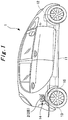
Fig. 1] Fig. 1 is a side view schematically illustrating an example of a vehicle to which a charging and discharging current quantity display device for an electric vehicle according to the present invention is applied. - [
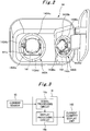
Fig. 2] Fig. 2 is a front view illustrating a charging and discharging current quantity display device for an electric vehicle according to a first embodiment of the present invention. - [
Fig. 3] Fig. 3 is a block diagram illustrating a configuration of a current quantity display controlling unit of the charging and discharging current quantity display device for an electric vehicle according to the first embodiment of the present invention. - [
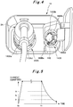
Fig. 4] Fig. 4 is an explanatory diagram illustrating the charging and discharging current quantity display device for an electric vehicle according to the first embodiment of the present invention with a charging connector connected to a regular charging port. - [
Fig. 5] Fig. 5 is a graph illustrating a change of electrical current during charging. - [
Fig. 6] Fig. 6 is an explanatory diagram illustrating indication examples of a current quantity display unit according to the first embodiment of the present invention.Fig. 6 (a) is an indication example for the case where current quantity i is 0 or more and less than i1;Fig. 6(b) , i1 or more and less than i2;Fig. 6(c) , i2 or more and less than i3; andFig. 6(d) , i3 or more. - [
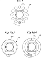
Fig. 7] Fig. 7 is a front view illustrating a charging and discharging current quantity display device for an electric vehicle according to a second embodiment of the present invention. - [
Fig. 8] Fig. 8 (a) is a front view illustrating another example of the charging and discharging current quantity display device for an electric vehicle according to the second embodiment of the present invention, andFig. 8 (b) is a front view of still another example of the charging and discharging current quantity display device for an electric vehicle according to the second embodiment of the present invention. - [
Fig. 9] Fig. 9 is a front view illustrating a charging and discharging current quantity display device for an electric vehicle according to a fourth embodiment of the present invention. - Hereinafter, referring to the attached drawings, descriptions are provided for details of a charging and discharging current quantity display device for an electric vehicle according to the present invention. Note that the present invention is not limited to the following embodiments, and various modifications are possible without departing from the gist of the present invention.
- Using
Figs. 1 to 6 , descriptions are provided for a charging and discharging current quantity display device for an electric vehicle according to a first embodiment of the present invention. As illustrated inFig. 1 , in this embodiment, anelectric vehicle 1 travels by driving anelectric motor 12 mounted in theelectric vehicle 1, using electric power stored in a battery (electricity storage means) 11. Supplied power is supplied from an external power supply through acharging connector 2 connected to a power-feed unit 14, and stored in thebattery 11 via acharging device 13. - As illustrated in
Fig. 2 , in this embodiment, the power-feed unit 14 is provided with aregular charging port 141 and arapid charging port 142. In addition, the power-feed unit 14 is also provided with a current quantity display unit (current quantity display means) 143A for regular charging and a current quantity display unit (current quantity display means) 143B for rapid charging. Hereinafter, when generically referring to the currentquantity display unit 143A for regular charging and the currentquantity display unit 143B for rapid charging, they are referred to as "currentquantity display units 143". - The
regular charging port 141 is provided with aregular charging socket 141a, to which aregular charging connector 2A (seeFig. 4 ) is attachably and detachably connected, theregular charging connector 2A being provided at an end of a low-voltage power cable extended from the external power supply (charging installation). In addition, therapid charging port 142 is provided with arapid charging socket 142a, to which arapid charging connector 2B (seeFig. 1 ) is attachably and detachably connected, therapid charging connector 2B being provided at an end of a high-voltage power cable extended from the external power supply (charging installation). - The current
quantity display unit 143A for regular charging and the currentquantity display unit 143B for rapid charging indicate a charging current quantity i of thebattery 11 flowing from theregular charging port 141 or therapid charging port 142 to thebattery 11 by turning on or off the light during charging, and indicate a discharging current quantity i of thebattery 11 flowing from thebattery 11 to theregular charging port 141 or therapid charging port 142 by turning on or off the light during discharging. Each of them is formed, for example, in an annular shape and surrounds theregular charging port 141 or therapid charging port 142. - Specifically, each of the current
quantity display unit 143A for regular charging and the currentquantity display unit 143B for rapid charging includes four current quantity display areas (indicators) arranged along the circumferential direction, in other words, arranged on the same circumference. Hereinafter, as viewed from the front of the currentquantity display units quantity display areas 143a"), current quantity display areas at the upper left are called current quantity display areas 143Ab and 143Bb (generically called "second currentquantity display areas 143b"), current quantity display areas at the upper right are called current quantity display areas 143Ac and 143Bc (generically called "third currentquantity display areas 143c"), and current quantity display areas at the lower right are called current quantity display areas 143Ad and 143Bd (generically called "fourth currentquantity display areas 143d"). - Here, a not-illustrated cable that connects between the
battery 11 and each of theregular charging port 141 and therapid charging port 142 is provided with a current sensor 15 (seeFig. 1 ) that detects current quantity i flowing through the cable. As illustrated inFig. 3 , the current quantity i detected by thecurrent sensor 15 is converted to a signal and inputted into a current quantitydisplay controlling unit 16. The current quantitydisplay controlling unit 16 includes asignal processing circuit 16a and adisplay processing circuit 16b. Thesignal processing circuit 16a processes a signal inputted from thecurrent sensor 15, and thedisplay processing circuit 16b determines whether to turn on or off each of the first to fourth currentquantity display areas 143a to 143d based on the current quantity i detected by thecurrent sensor 15 and sends control signals to the currentquantity display units 143. In this way, turning on and off the first to fourth currentquantity display areas 143a to 143d is controlled in accordance with the current quantity i detected by thecurrent sensor 15. - Note that in this embodiment, as illustrated in
Fig. 4 , for example, when thebattery 11 is charged with a homeuse charging connector 2A connected to theregular charging socket 141a, the currentquantity display unit 143A for regular charging displays an indication in accordance with the magnitude of the current quantity i based on the control signal inputted from the current quantitydisplay controlling unit 16. When thebattery 11 is charged with arapid charging connector 2B, which is provided at an end of the high-voltage cable, connected to therapid charging socket 142a, the currentquantity display unit 143B for rapid charging displays an indication in accordance with the magnitude of the current quantity i based on the control signal inputted from the current quantitydisplay controlling unit 16. - Hereinafter, using
Figs. 5 and6 , descriptions are provided for indication examples for the current quantity i according to this embodiment. Note that inFig. 6 , lighting areas are represented by hatching, and light-out areas are represented by outlines. The same applies toFigs. 7 to 9 to be described later. - As illustrated in
Fig. 5 , when thebattery 11 is charged, constant current charging is performed until the charged amount reaches a specified value (for example, about 80%, assuming full charge is 100%) (from t = to to t = t1 inFig. 5 ). On the other hand, constant voltage charge is performed when the charged amount is more than or equal to a specified value (after t = t1 inFig. 5 ), and the current quantity i decreases as the charged amount increases. - In this embodiment, when the current quantity i is 0 < i < i1, the first current
quantity display area 143a is turned on while the second to fourth currentquantity display areas 143b to 143d are turned off as illustrated inFig. 6(a) . When the current quantity i is i1 ≤ i ≤ i2, the first and second currentquantity display areas quantity display areas Fig. 6(b) . When the current quantity i is i2 ≤ i < i3, the first to third currentquantity display areas 143a to 143c are turned on while the fourth currentquantity display area 143d is turned off as illustrated inFig. 6 (c) . When the current quantity i is i3 ≤ i, all the first to fourth currentquantity display areas 143a to 143d are turned on as illustrated inFig. 6(d) . Note that although not illustrated, when the current quantity i is i = 0, all the first to fourth currentquantity display areas 143a to 143d are turned off. - Here, the current quantities i1 to i3 may be set as appropriate in accordance with the condition. For example, if the maximum value of the current quantity i is 16 A, for example, i1, i2, and i3 may be 4, 8, and 12 A, respectively.
- The charging and discharging current quantity display device for an electric vehicle according to this embodiment, which is configured as described above, allows the user to visually recognize approximately how much current is flowing when charging or discharging the
battery 11. - In addition, the user can recognize the charging status sensuously. For example, when a current
quantity display unit 143 displays an indication illustrated inFig. 6(a) some time after charging starts, the user can recognize that charging is reaching the end. - Note that although an example is shown in the embodiment described above in which the current
quantity display unit 143 is provided in the annular shape to surround the charging port, the present invention is not limited to the embodiment described above. The currentquantity display unit 143 may be formed in an ellipse shape or a star shape and surround the charging port, for example. Or alternatively, the first to fourth currentquantity display areas 143a to 143d may be linearly arranged, for example. - Using
Figs. 7 and 8 , descriptions are provided for a charging and discharging current quantity display device for an electric vehicle according to a second embodiment of the present invention. - The charging and discharging current quantity display device for an electric vehicle according to this embodiment employs a current quantity display unit (current quantity display means) 144 illustrated in
Fig. 7 instead of the currentquantity display unit 143 in the first embodiment. Other configuration is the same as that in the first embodiment described above. Hence, hereinafter repetitive descriptions are omitted, and descriptions are provided denoting the same parts by the same reference signs. - The current
quantity display unit 144, designed to indicate the current quantity i flowing through the regular chargingport 141 and the rapid chargingport 142 by blinking or turning off, includes twelve circularcurrent quantity indicators 144a arranged on the same circumference with the same intervals, surrounding the regular chargingport 141 and the rapid chargingport 142. - In this embodiment, when the
battery 11 is charged with the homeuse charging connector 2 connected to theregular charging socket 141a, or when thebattery 11 is charged with the rapid charging connector, which is provided at an end of the non-illustrated high-voltage cable, to therapid charging socket 142a, the currentquantity display unit 144 provided at each of the regular chargingport 141 and the rapid chargingport 142 displays an indication according to the magnitude of the current quantity i based on the information inputted from the current quantitydisplay controlling unit 16 by turning on and off (blinking) eachcurrent quantity indicator 144a sequentially in the circumferential direction (one direction). - To be specific, for example, in the case where the current quantity i is small according to the information inputted from the current quantity
display controlling unit 16, an interval from the timing of turning on acurrent indicator 144a to the timing of turning on the nextcurrent indicator 144a is increased, compared to the case where the current quantity i is large. In other words, control is performed such that when the current quantity i is small, eachcurrent quantity indicator 144a turns on and off (blinks) sequentially in a circumferential direction at a slow rotational speed, and when the current quantity i is large, eachcurrent quantity indicator 144a turns on and off (blinks) sequentially in the circumferential direction at a fast rotational speed. - The charging and discharging current quantity display device for an electric vehicle according to this embodiment, which is configured as described above, allows the user to visually recognize the charging and discharging current quantity i of the
battery 11 as in the first embodiment described above. - Note that the present invention is not limited to the embodiment described above. For example, as illustrated in
Figs. 8 (a) and 8 (b) , the current quantity display unit may be a currentquantity display unit 145 including dot-shapedcurrent quantity indicators 145a arranged on the same circumference with the same intervals, or may be a currentquantity display unit 146 including face-shapedcurrent quantity indicators 146a arranged on the same circumference in a circular shape. In addition, the shape of the current quantity indicators is not limited to a circular shape, but may be another shape as long as they can surround each of the regular chargingport 141 and the rapid chargingport 142. - Hereinafter, descriptions are provided for a charging and discharging current quantity display device for an electric vehicle according to a third embodiment of the present invention.
- The charging and discharging current quantity display device for an electric vehicle according to this embodiment is based on the charging and discharging current quantity display device for an electric vehicle of the second embodiment illustrated in
Figs. 7 and 8 , and is configured such that thecurrent quantity indicators 144a (, 145a, or 146a) are sequentially turned on and off in different directions (courses) when thebattery 11 is charged and when thebattery 11 is discharged. - In other words, for example, when the
battery 11 is charged, thecurrent quantity indicators 144a (, 145a, or 146a) turn on and off (blink) sequentially clockwise, and when thebattery 11 is discharged, thecurrent quantity indicators 144a (, 145a, or 146a) turn on and off sequentially counterclockwise. - Other configuration is the same as that in the second embodiment described above, and repetitive descriptions are omitted.
- The charging and discharging current quantity display device for an electric vehicle according to this embodiment, which is configured as described above, allows the user to visually recognize which of charging and discharging is ongoing, in addition to the effects of the second embodiment.
- Hereinafter, using
Fig. 9 , descriptions are provided for a charging and discharging current quantity display device for an electric vehicle according to a fourth embodiment of the present invention. - As illustrated in
Fig. 9 , the charging and discharging current quantity display device for an electric vehicle according to this embodiment is an example in which a currentquantity display unit 147 is provided so as to surround both the regular chargingport 141 and the rapid chargingport 142. The structure of the currentquantity display unit 147 is the same as that of the currentquantity display unit Fig. 9 illustrates an example to which the same structure as that of the currentquantity display unit 143 described in the first embodiment is applied), and here detailed descriptions are omitted. - The charging and discharging current quantity display device for an electric vehicle according to this embodiment, which is configured as described above, provides the same operations and effects as in the first to third embodiment.
- The present invention is applicable and preferable to a charging and discharging current quantity display device for an electric vehicle.
-
- 1 electric vehicle
- 2 charging connector
- 2A regular charging connector
- 2B rapid charging connector
- 11 battery
- 12 electric motor
- 13 charging device
- 14 power-feed unit
- 15 current sensor
- 16 current quantity display controlling unit
- 16a signal processing circuit
- 16b display processing circuit
- 141 regular charging port
- 142 rapid charging port
- 143, 144, 145, 146, 147 current quantity display unit
- 143a to 143d first to fourth current quantity display areas
- 143A current quantity display unit for regular charging
- 143Aa to 143Ad first to fourth current quantity display areas
- 143B current quantity display unit for rapid charging
- 143Ba to 143Bd first to fourth current quantity display areas
- 145a, 146a current quantity indicator
- 147a to 147d first to fourth current quantity display areas
Claims (5)
- A charging and discharging current quantity display device for an electric vehicle including a power-feed unit having a charging port and electricity storage means which is charged by electric power supplied from an external power supply through the charging port, characterized in that the charging and discharging current quantity display device for an electric vehicle comprises:current quantity detection means that detects a charging and discharging current quantity of the electricity storage means;current quantity display means that includes a plurality of indicators arranged at the power-feed unit and indicates the magnitude of the charging and discharging current quantity of the electricity storage means by changing lighting states of the indicators; andcurrent quantity display controlling means that controls a lighting state of each of the indicators in accordance with the current quantity detected by the current quantity detection means.
- The charging and discharging current quantity display device for an electric vehicle according to claim 1, characterized in that
the indicators are arranged around the charging port. - The charging and discharging current quantity display device for an electric vehicle according to claim 1 or 2, characterized in that
the current quantity display controlling means changes the number of indicators to turn on in accordance with the current quantity detected by the current quantity detection means. - The charging and discharging current quantity display device for an electric vehicle according to claim 2, characterized in that
the current quantity display controlling means controls the lighting states of the indicators such that each of the indicators blinks sequentially in one direction and changes a speed at which each of the indicators blinks sequentially in the one direction, in accordance with the current quantity detected by the current quantity detection means. - The charging and discharging current quantity display device for an electric vehicle according to any one of claims 1 to 4, characterized in that
the power-feed unit has two charging ports, and the indicators are arranged to surround the two charging ports.
Applications Claiming Priority (2)
| Application Number | Priority Date | Filing Date | Title |
|---|---|---|---|
| JP2014245521A JP6402384B2 (en) | 2014-12-04 | 2014-12-04 | Charge / discharge current amount display device for electric vehicle |
| PCT/JP2015/082060 WO2016088537A1 (en) | 2014-12-04 | 2015-11-16 | Charging and discharging current quantity display device for electric vehicle |
Publications (3)
| Publication Number | Publication Date |
|---|---|
| EP3185391A1 true EP3185391A1 (en) | 2017-06-28 |
| EP3185391A4 EP3185391A4 (en) | 2018-04-25 |
| EP3185391B1 EP3185391B1 (en) | 2019-04-03 |
Family
ID=56091487
Family Applications (1)
| Application Number | Title | Priority Date | Filing Date |
|---|---|---|---|
| EP15864953.3A Active EP3185391B1 (en) | 2014-12-04 | 2015-11-16 | Charging and discharging current quantity display device for electric vehicle |
Country Status (5)
| Country | Link |
|---|---|
| US (1) | US10189361B2 (en) |
| EP (1) | EP3185391B1 (en) |
| JP (1) | JP6402384B2 (en) |
| CN (1) | CN106716773A (en) |
| WO (1) | WO2016088537A1 (en) |
Cited By (1)
| Publication number | Priority date | Publication date | Assignee | Title |
|---|---|---|---|---|
| IT202000003395A1 (en) * | 2020-02-19 | 2021-08-19 | Automobili Pininfarina GmbH | CHARGE INDICATOR FOR ELECTRIC DRIVE VEHICLES |
Families Citing this family (13)
| Publication number | Priority date | Publication date | Assignee | Title |
|---|---|---|---|---|
| JP6747915B2 (en) * | 2016-08-30 | 2020-08-26 | ダイキョーニシカワ株式会社 | Vehicle alarm system |
| WO2018145324A1 (en) * | 2017-02-13 | 2018-08-16 | Tti (Macao Commercial Offshore) Limited | Rechargeable battery pack |
| US20190372377A1 (en) * | 2018-06-01 | 2019-12-05 | Flag Acquisition, Llc | Systems and methods for charging one or more electronic devices |
| JP7103127B2 (en) * | 2018-09-28 | 2022-07-20 | トヨタ自動車株式会社 | In-vehicle control device and vehicle |
| JP7147457B2 (en) * | 2018-10-18 | 2022-10-05 | トヨタ自動車株式会社 | Vehicle and charging system |
| JP7200599B2 (en) * | 2018-10-23 | 2023-01-10 | トヨタ自動車株式会社 | vehicle |
| WO2021070284A1 (en) * | 2019-10-09 | 2021-04-15 | 日産自動車株式会社 | Charging port device for vehicle |
| JP6983847B2 (en) * | 2019-10-21 | 2021-12-17 | ヤマハ発動機株式会社 | Saddle-type electric vehicle |
| US11623562B2 (en) * | 2020-01-15 | 2023-04-11 | Aptiv Technologies Limited | Light control apparatus and method |
| US11230203B2 (en) * | 2020-01-30 | 2022-01-25 | Ford Global Technologies, Llc | Selective illumination of charging port status indicators for an electrified vehicle |
| CN114475294A (en) * | 2020-11-11 | 2022-05-13 | 本田技研工业(中国)投资有限公司 | Vehicle charging status indication system, vehicle power supply status indication system and vehicle |
| IT202200022761A1 (en) * | 2022-11-04 | 2024-05-04 | Ferrari Spa | MOTOR VEHICLE WITH ELECTRIC CHARGING SOCKET DOOR EQUIPPED WITH A SCREEN TO DISPLAY CHARGING INFORMATION |
| US12342104B2 (en) | 2023-11-09 | 2025-06-24 | Honda Motor Co., Ltd. | Integrated display for electrified vehicle charge port |
Family Cites Families (11)
| Publication number | Priority date | Publication date | Assignee | Title |
|---|---|---|---|---|
| JP3252035B2 (en) * | 1993-09-14 | 2002-01-28 | 本田技研工業株式会社 | Electric vehicle charging display |
| US7091874B2 (en) * | 2003-04-18 | 2006-08-15 | Smithson Bradley D | Temperature compensated warning light |
| JP4864791B2 (en) * | 2007-03-29 | 2012-02-01 | トヨタ自動車株式会社 | Charging cable and charging system |
| JP2009077550A (en) | 2007-09-21 | 2009-04-09 | Toshiba Plant Systems & Services Corp | Fast charger |
| US8317376B2 (en) * | 2009-03-27 | 2012-11-27 | Magna Mirrors Of America, Inc. | Illuminated bezel of charge port for electric vehicle |
| WO2010140253A1 (en) * | 2009-06-05 | 2010-12-09 | トヨタ自動車株式会社 | Electric car, and wholly allowable discharge electric energy setting method in the electric car |
| US7999665B2 (en) * | 2009-08-18 | 2011-08-16 | Ford Global Technologies, Llc | Plug-in vehicle having a recharging port with a state of charge indicator |
| WO2012049733A1 (en) * | 2010-10-12 | 2012-04-19 | トヨタ車体 株式会社 | Device for detecting opening/closing of charger lid |
| US8350526B2 (en) * | 2011-07-25 | 2013-01-08 | Lightening Energy | Station for rapidly charging an electric vehicle battery |
| JP6019222B2 (en) * | 2012-05-31 | 2016-11-02 | コリア レイルロード リサーチ インスティチュート | Multi-function charger for electric vehicle for DC distribution network using large capacity DC-DC converter |
| JP2014096927A (en) | 2012-11-09 | 2014-05-22 | Nyk Trading Corp | Power supply system and device |
-
2014
- 2014-12-04 JP JP2014245521A patent/JP6402384B2/en active Active
-
2015
- 2015-11-16 CN CN201580050977.7A patent/CN106716773A/en active Pending
- 2015-11-16 WO PCT/JP2015/082060 patent/WO2016088537A1/en not_active Ceased
- 2015-11-16 EP EP15864953.3A patent/EP3185391B1/en active Active
-
2017
- 2017-03-20 US US15/463,256 patent/US10189361B2/en active Active
Cited By (3)
| Publication number | Priority date | Publication date | Assignee | Title |
|---|---|---|---|---|
| IT202000003395A1 (en) * | 2020-02-19 | 2021-08-19 | Automobili Pininfarina GmbH | CHARGE INDICATOR FOR ELECTRIC DRIVE VEHICLES |
| WO2021165825A1 (en) * | 2020-02-19 | 2021-08-26 | Automobili Pininfarina GmbH | Charge visual display for electric vehicles |
| US12109910B2 (en) | 2020-02-19 | 2024-10-08 | Automobili Pininfarina GmbH | Charge visual display for electric vehicles |
Also Published As
| Publication number | Publication date |
|---|---|
| EP3185391B1 (en) | 2019-04-03 |
| US10189361B2 (en) | 2019-01-29 |
| CN106716773A (en) | 2017-05-24 |
| WO2016088537A1 (en) | 2016-06-09 |
| EP3185391A4 (en) | 2018-04-25 |
| JP6402384B2 (en) | 2018-10-10 |
| JP2016111775A (en) | 2016-06-20 |
| US20170197516A1 (en) | 2017-07-13 |
Similar Documents
| Publication | Publication Date | Title |
|---|---|---|
| EP3185391B1 (en) | Charging and discharging current quantity display device for electric vehicle | |
| JP5482908B2 (en) | Vehicle power supply system and vehicle equipped with the same | |
| EP3012145A1 (en) | Power supply device for auxiliary device battery | |
| US8319472B2 (en) | Method and system for internally jump-starting an engine | |
| US10000137B2 (en) | Hybrid vehicle with means for disconnection of a depleted auxiliary battery in order to allow for more rapid main battery charging | |
| JP5307685B2 (en) | Control device and control method for plug-in charging vehicle | |
| KR101619618B1 (en) | Vehicle charger and method for controlling power thereof | |
| KR102147321B1 (en) | Battery Discharge Preventing System and Method Using the Same for Hybrid Vehicle | |
| US20180131208A1 (en) | Apparatus for preventing over-discharge of battery | |
| US20150326050A1 (en) | Method and controller for controlling scheduled charging of electric vehicle | |
| US11435388B2 (en) | Electric vehicle and control method for electric vehicle | |
| US11292358B2 (en) | Vehicle and control method for vehicle | |
| US11292350B2 (en) | Vehicle and charging system | |
| JP5361655B2 (en) | Control apparatus and control method | |
| JP2013150421A (en) | Electric vehicle | |
| JP3151047U (en) | Electric vehicle quick charging equipment | |
| JP2015503477A (en) | Method for checking no-voltage condition in high voltage system and high voltage system | |
| JP6573528B2 (en) | Vehicle charging system | |
| CN108001226A (en) | Electric vehicle | |
| EP3020594A1 (en) | Electrically powered vehicle and power supply system | |
| JP2011109793A (en) | Device and method for controlling plug-in charging vehicle | |
| JP2013112303A (en) | Power supply device for hybrid vehicle | |
| JP6576816B2 (en) | Vehicle charging device and vehicle charging system | |
| JP2013158202A (en) | Device for detecting charge connection | |
| JP2016059137A (en) | Charge / discharge control device |
Legal Events
| Date | Code | Title | Description |
|---|---|---|---|
| STAA | Information on the status of an ep patent application or granted ep patent |
Free format text: STATUS: THE INTERNATIONAL PUBLICATION HAS BEEN MADE |
|
| PUAI | Public reference made under article 153(3) epc to a published international application that has entered the european phase |
Free format text: ORIGINAL CODE: 0009012 |
|
| STAA | Information on the status of an ep patent application or granted ep patent |
Free format text: STATUS: REQUEST FOR EXAMINATION WAS MADE |
|
| 17P | Request for examination filed |
Effective date: 20170320 |
|
| AK | Designated contracting states |
Kind code of ref document: A1 Designated state(s): AL AT BE BG CH CY CZ DE DK EE ES FI FR GB GR HR HU IE IS IT LI LT LU LV MC MK MT NL NO PL PT RO RS SE SI SK SM TR |
|
| AX | Request for extension of the european patent |
Extension state: BA ME |
|
| DAV | Request for validation of the european patent (deleted) | ||
| DAX | Request for extension of the european patent (deleted) | ||
| A4 | Supplementary search report drawn up and despatched |
Effective date: 20180322 |
|
| RIC1 | Information provided on ipc code assigned before grant |
Ipc: H02J 7/00 20060101ALI20180316BHEP Ipc: B60L 11/18 20060101AFI20180316BHEP Ipc: H02J 7/02 20160101ALN20180316BHEP Ipc: G01R 31/36 20060101ALN20180316BHEP |
|
| REG | Reference to a national code |
Ref country code: DE Ref legal event code: R079 Ref document number: 602015027821 Country of ref document: DE Free format text: PREVIOUS MAIN CLASS: H02J0007020000 Ipc: B60L0011180000 |
|
| GRAP | Despatch of communication of intention to grant a patent |
Free format text: ORIGINAL CODE: EPIDOSNIGR1 |
|
| STAA | Information on the status of an ep patent application or granted ep patent |
Free format text: STATUS: GRANT OF PATENT IS INTENDED |
|
| RIC1 | Information provided on ipc code assigned before grant |
Ipc: G01R 31/36 20060101ALN20181115BHEP Ipc: H02J 7/02 20160101ALN20181115BHEP Ipc: H02J 7/00 20060101ALI20181115BHEP Ipc: B60L 11/18 20060101AFI20181115BHEP |
|
| INTG | Intention to grant announced |
Effective date: 20181211 |
|
| GRAS | Grant fee paid |
Free format text: ORIGINAL CODE: EPIDOSNIGR3 |
|
| GRAA | (expected) grant |
Free format text: ORIGINAL CODE: 0009210 |
|
| STAA | Information on the status of an ep patent application or granted ep patent |
Free format text: STATUS: THE PATENT HAS BEEN GRANTED |
|
| AK | Designated contracting states |
Kind code of ref document: B1 Designated state(s): AL AT BE BG CH CY CZ DE DK EE ES FI FR GB GR HR HU IE IS IT LI LT LU LV MC MK MT NL NO PL PT RO RS SE SI SK SM TR |
|
| REG | Reference to a national code |
Ref country code: GB Ref legal event code: FG4D |
|
| REG | Reference to a national code |
Ref country code: CH Ref legal event code: EP Ref country code: AT Ref legal event code: REF Ref document number: 1115296 Country of ref document: AT Kind code of ref document: T Effective date: 20190415 |
|
| REG | Reference to a national code |
Ref country code: DE Ref legal event code: R096 Ref document number: 602015027821 Country of ref document: DE |
|
| REG | Reference to a national code |
Ref country code: IE Ref legal event code: FG4D |
|
| RAP2 | Party data changed (patent owner data changed or rights of a patent transferred) |
Owner name: MITSUBISHI JIDOSHA KOGYO KABUSHIKI KAISHA |
|
| REG | Reference to a national code |
Ref country code: NL Ref legal event code: MP Effective date: 20190403 |
|
| REG | Reference to a national code |
Ref country code: LT Ref legal event code: MG4D |
|
| REG | Reference to a national code |
Ref country code: AT Ref legal event code: MK05 Ref document number: 1115296 Country of ref document: AT Kind code of ref document: T Effective date: 20190403 |
|
| PG25 | Lapsed in a contracting state [announced via postgrant information from national office to epo] |
Ref country code: NL Free format text: LAPSE BECAUSE OF FAILURE TO SUBMIT A TRANSLATION OF THE DESCRIPTION OR TO PAY THE FEE WITHIN THE PRESCRIBED TIME-LIMIT Effective date: 20190403 |
|
| PG25 | Lapsed in a contracting state [announced via postgrant information from national office to epo] |
Ref country code: CZ Free format text: LAPSE BECAUSE OF FAILURE TO SUBMIT A TRANSLATION OF THE DESCRIPTION OR TO PAY THE FEE WITHIN THE PRESCRIBED TIME-LIMIT Effective date: 20190403 Ref country code: FI Free format text: LAPSE BECAUSE OF FAILURE TO SUBMIT A TRANSLATION OF THE DESCRIPTION OR TO PAY THE FEE WITHIN THE PRESCRIBED TIME-LIMIT Effective date: 20190403 Ref country code: NO Free format text: LAPSE BECAUSE OF FAILURE TO SUBMIT A TRANSLATION OF THE DESCRIPTION OR TO PAY THE FEE WITHIN THE PRESCRIBED TIME-LIMIT Effective date: 20190703 Ref country code: SE Free format text: LAPSE BECAUSE OF FAILURE TO SUBMIT A TRANSLATION OF THE DESCRIPTION OR TO PAY THE FEE WITHIN THE PRESCRIBED TIME-LIMIT Effective date: 20190403 Ref country code: AL Free format text: LAPSE BECAUSE OF FAILURE TO SUBMIT A TRANSLATION OF THE DESCRIPTION OR TO PAY THE FEE WITHIN THE PRESCRIBED TIME-LIMIT Effective date: 20190403 Ref country code: PT Free format text: LAPSE BECAUSE OF FAILURE TO SUBMIT A TRANSLATION OF THE DESCRIPTION OR TO PAY THE FEE WITHIN THE PRESCRIBED TIME-LIMIT Effective date: 20190803 Ref country code: HR Free format text: LAPSE BECAUSE OF FAILURE TO SUBMIT A TRANSLATION OF THE DESCRIPTION OR TO PAY THE FEE WITHIN THE PRESCRIBED TIME-LIMIT Effective date: 20190403 Ref country code: LT Free format text: LAPSE BECAUSE OF FAILURE TO SUBMIT A TRANSLATION OF THE DESCRIPTION OR TO PAY THE FEE WITHIN THE PRESCRIBED TIME-LIMIT Effective date: 20190403 Ref country code: ES Free format text: LAPSE BECAUSE OF FAILURE TO SUBMIT A TRANSLATION OF THE DESCRIPTION OR TO PAY THE FEE WITHIN THE PRESCRIBED TIME-LIMIT Effective date: 20190403 |
|
| PG25 | Lapsed in a contracting state [announced via postgrant information from national office to epo] |
Ref country code: LV Free format text: LAPSE BECAUSE OF FAILURE TO SUBMIT A TRANSLATION OF THE DESCRIPTION OR TO PAY THE FEE WITHIN THE PRESCRIBED TIME-LIMIT Effective date: 20190403 Ref country code: RS Free format text: LAPSE BECAUSE OF FAILURE TO SUBMIT A TRANSLATION OF THE DESCRIPTION OR TO PAY THE FEE WITHIN THE PRESCRIBED TIME-LIMIT Effective date: 20190403 Ref country code: BG Free format text: LAPSE BECAUSE OF FAILURE TO SUBMIT A TRANSLATION OF THE DESCRIPTION OR TO PAY THE FEE WITHIN THE PRESCRIBED TIME-LIMIT Effective date: 20190703 Ref country code: GR Free format text: LAPSE BECAUSE OF FAILURE TO SUBMIT A TRANSLATION OF THE DESCRIPTION OR TO PAY THE FEE WITHIN THE PRESCRIBED TIME-LIMIT Effective date: 20190704 Ref country code: PL Free format text: LAPSE BECAUSE OF FAILURE TO SUBMIT A TRANSLATION OF THE DESCRIPTION OR TO PAY THE FEE WITHIN THE PRESCRIBED TIME-LIMIT Effective date: 20190403 |
|
| PG25 | Lapsed in a contracting state [announced via postgrant information from national office to epo] |
Ref country code: IS Free format text: LAPSE BECAUSE OF FAILURE TO SUBMIT A TRANSLATION OF THE DESCRIPTION OR TO PAY THE FEE WITHIN THE PRESCRIBED TIME-LIMIT Effective date: 20190803 Ref country code: AT Free format text: LAPSE BECAUSE OF FAILURE TO SUBMIT A TRANSLATION OF THE DESCRIPTION OR TO PAY THE FEE WITHIN THE PRESCRIBED TIME-LIMIT Effective date: 20190403 |
|
| REG | Reference to a national code |
Ref country code: DE Ref legal event code: R097 Ref document number: 602015027821 Country of ref document: DE |
|
| PG25 | Lapsed in a contracting state [announced via postgrant information from national office to epo] |
Ref country code: SK Free format text: LAPSE BECAUSE OF FAILURE TO SUBMIT A TRANSLATION OF THE DESCRIPTION OR TO PAY THE FEE WITHIN THE PRESCRIBED TIME-LIMIT Effective date: 20190403 Ref country code: DK Free format text: LAPSE BECAUSE OF FAILURE TO SUBMIT A TRANSLATION OF THE DESCRIPTION OR TO PAY THE FEE WITHIN THE PRESCRIBED TIME-LIMIT Effective date: 20190403 Ref country code: EE Free format text: LAPSE BECAUSE OF FAILURE TO SUBMIT A TRANSLATION OF THE DESCRIPTION OR TO PAY THE FEE WITHIN THE PRESCRIBED TIME-LIMIT Effective date: 20190403 Ref country code: RO Free format text: LAPSE BECAUSE OF FAILURE TO SUBMIT A TRANSLATION OF THE DESCRIPTION OR TO PAY THE FEE WITHIN THE PRESCRIBED TIME-LIMIT Effective date: 20190403 |
|
| PLBE | No opposition filed within time limit |
Free format text: ORIGINAL CODE: 0009261 |
|
| STAA | Information on the status of an ep patent application or granted ep patent |
Free format text: STATUS: NO OPPOSITION FILED WITHIN TIME LIMIT |
|
| PG25 | Lapsed in a contracting state [announced via postgrant information from national office to epo] |
Ref country code: IT Free format text: LAPSE BECAUSE OF FAILURE TO SUBMIT A TRANSLATION OF THE DESCRIPTION OR TO PAY THE FEE WITHIN THE PRESCRIBED TIME-LIMIT Effective date: 20190403 Ref country code: SM Free format text: LAPSE BECAUSE OF FAILURE TO SUBMIT A TRANSLATION OF THE DESCRIPTION OR TO PAY THE FEE WITHIN THE PRESCRIBED TIME-LIMIT Effective date: 20190403 |
|
| 26N | No opposition filed |
Effective date: 20200106 |
|
| PG25 | Lapsed in a contracting state [announced via postgrant information from national office to epo] |
Ref country code: TR Free format text: LAPSE BECAUSE OF FAILURE TO SUBMIT A TRANSLATION OF THE DESCRIPTION OR TO PAY THE FEE WITHIN THE PRESCRIBED TIME-LIMIT Effective date: 20190403 |
|
| PG25 | Lapsed in a contracting state [announced via postgrant information from national office to epo] |
Ref country code: SI Free format text: LAPSE BECAUSE OF FAILURE TO SUBMIT A TRANSLATION OF THE DESCRIPTION OR TO PAY THE FEE WITHIN THE PRESCRIBED TIME-LIMIT Effective date: 20190403 |
|
| REG | Reference to a national code |
Ref country code: CH Ref legal event code: PL |
|
| PG25 | Lapsed in a contracting state [announced via postgrant information from national office to epo] |
Ref country code: LU Free format text: LAPSE BECAUSE OF NON-PAYMENT OF DUE FEES Effective date: 20191116 Ref country code: LI Free format text: LAPSE BECAUSE OF NON-PAYMENT OF DUE FEES Effective date: 20191130 Ref country code: CH Free format text: LAPSE BECAUSE OF NON-PAYMENT OF DUE FEES Effective date: 20191130 Ref country code: MC Free format text: LAPSE BECAUSE OF FAILURE TO SUBMIT A TRANSLATION OF THE DESCRIPTION OR TO PAY THE FEE WITHIN THE PRESCRIBED TIME-LIMIT Effective date: 20190403 |
|
| REG | Reference to a national code |
Ref country code: BE Ref legal event code: MM Effective date: 20191130 |
|
| PG25 | Lapsed in a contracting state [announced via postgrant information from national office to epo] |
Ref country code: IE Free format text: LAPSE BECAUSE OF NON-PAYMENT OF DUE FEES Effective date: 20191116 |
|
| PG25 | Lapsed in a contracting state [announced via postgrant information from national office to epo] |
Ref country code: BE Free format text: LAPSE BECAUSE OF NON-PAYMENT OF DUE FEES Effective date: 20191130 |
|
| PG25 | Lapsed in a contracting state [announced via postgrant information from national office to epo] |
Ref country code: CY Free format text: LAPSE BECAUSE OF FAILURE TO SUBMIT A TRANSLATION OF THE DESCRIPTION OR TO PAY THE FEE WITHIN THE PRESCRIBED TIME-LIMIT Effective date: 20190403 |
|
| PG25 | Lapsed in a contracting state [announced via postgrant information from national office to epo] |
Ref country code: MT Free format text: LAPSE BECAUSE OF FAILURE TO SUBMIT A TRANSLATION OF THE DESCRIPTION OR TO PAY THE FEE WITHIN THE PRESCRIBED TIME-LIMIT Effective date: 20190403 Ref country code: HU Free format text: LAPSE BECAUSE OF FAILURE TO SUBMIT A TRANSLATION OF THE DESCRIPTION OR TO PAY THE FEE WITHIN THE PRESCRIBED TIME-LIMIT; INVALID AB INITIO Effective date: 20151116 |
|
| PG25 | Lapsed in a contracting state [announced via postgrant information from national office to epo] |
Ref country code: MK Free format text: LAPSE BECAUSE OF FAILURE TO SUBMIT A TRANSLATION OF THE DESCRIPTION OR TO PAY THE FEE WITHIN THE PRESCRIBED TIME-LIMIT Effective date: 20190403 |
|
| PGFP | Annual fee paid to national office [announced via postgrant information from national office to epo] |
Ref country code: DE Payment date: 20241001 Year of fee payment: 10 |
|
| PGFP | Annual fee paid to national office [announced via postgrant information from national office to epo] |
Ref country code: GB Payment date: 20241001 Year of fee payment: 10 |
|
| PGFP | Annual fee paid to national office [announced via postgrant information from national office to epo] |
Ref country code: FR Payment date: 20241001 Year of fee payment: 10 |