EP3185337A1 - Battery conncetor and circuit module - Google Patents
Battery conncetor and circuit module Download PDFInfo
- Publication number
- EP3185337A1 EP3185337A1 EP16205564.4A EP16205564A EP3185337A1 EP 3185337 A1 EP3185337 A1 EP 3185337A1 EP 16205564 A EP16205564 A EP 16205564A EP 3185337 A1 EP3185337 A1 EP 3185337A1
- Authority
- EP
- European Patent Office
- Prior art keywords
- conductive portion
- button battery
- circuit board
- limiting space
- insulating housing
- Prior art date
- Legal status (The legal status is an assumption and is not a legal conclusion. Google has not performed a legal analysis and makes no representation as to the accuracy of the status listed.)
- Granted
Links
- 230000000694 effects Effects 0.000 description 2
- 239000004973 liquid crystal related substance Substances 0.000 description 1
- 238000012986 modification Methods 0.000 description 1
- 230000004048 modification Effects 0.000 description 1
- 230000003287 optical effect Effects 0.000 description 1
Images




Classifications
-
- H—ELECTRICITY
- H01—ELECTRIC ELEMENTS
- H01R—ELECTRICALLY-CONDUCTIVE CONNECTIONS; STRUCTURAL ASSOCIATIONS OF A PLURALITY OF MUTUALLY-INSULATED ELECTRICAL CONNECTING ELEMENTS; COUPLING DEVICES; CURRENT COLLECTORS
- H01R33/00—Coupling devices specially adapted for supporting apparatus and having one part acting as a holder providing support and electrical connection via a counterpart which is structurally associated with the apparatus, e.g. lamp holders; Separate parts thereof
- H01R33/05—Two-pole devices
- H01R33/18—Two-pole devices having only abutting contacts
-
- H—ELECTRICITY
- H01—ELECTRIC ELEMENTS
- H01M—PROCESSES OR MEANS, e.g. BATTERIES, FOR THE DIRECT CONVERSION OF CHEMICAL ENERGY INTO ELECTRICAL ENERGY
- H01M10/00—Secondary cells; Manufacture thereof
- H01M10/42—Methods or arrangements for servicing or maintenance of secondary cells or secondary half-cells
- H01M10/425—Structural combination with electronic components, e.g. electronic circuits integrated to the outside of the casing
-
- H—ELECTRICITY
- H01—ELECTRIC ELEMENTS
- H01M—PROCESSES OR MEANS, e.g. BATTERIES, FOR THE DIRECT CONVERSION OF CHEMICAL ENERGY INTO ELECTRICAL ENERGY
- H01M10/00—Secondary cells; Manufacture thereof
- H01M10/42—Methods or arrangements for servicing or maintenance of secondary cells or secondary half-cells
- H01M10/48—Accumulators combined with arrangements for measuring, testing or indicating the condition of cells, e.g. the level or density of the electrolyte
- H01M10/488—Cells or batteries combined with indicating means for external visualization of the condition, e.g. by change of colour or of light density
-
- H—ELECTRICITY
- H01—ELECTRIC ELEMENTS
- H01M—PROCESSES OR MEANS, e.g. BATTERIES, FOR THE DIRECT CONVERSION OF CHEMICAL ENERGY INTO ELECTRICAL ENERGY
- H01M50/00—Constructional details or processes of manufacture of the non-active parts of electrochemical cells other than fuel cells, e.g. hybrid cells
- H01M50/20—Mountings; Secondary casings or frames; Racks, modules or packs; Suspension devices; Shock absorbers; Transport or carrying devices; Holders
- H01M50/204—Racks, modules or packs for multiple batteries or multiple cells
- H01M50/207—Racks, modules or packs for multiple batteries or multiple cells characterised by their shape
- H01M50/216—Racks, modules or packs for multiple batteries or multiple cells characterised by their shape adapted for button or coin cells
-
- H—ELECTRICITY
- H01—ELECTRIC ELEMENTS
- H01M—PROCESSES OR MEANS, e.g. BATTERIES, FOR THE DIRECT CONVERSION OF CHEMICAL ENERGY INTO ELECTRICAL ENERGY
- H01M50/00—Constructional details or processes of manufacture of the non-active parts of electrochemical cells other than fuel cells, e.g. hybrid cells
- H01M50/50—Current conducting connections for cells or batteries
-
- H—ELECTRICITY
- H01—ELECTRIC ELEMENTS
- H01R—ELECTRICALLY-CONDUCTIVE CONNECTIONS; STRUCTURAL ASSOCIATIONS OF A PLURALITY OF MUTUALLY-INSULATED ELECTRICAL CONNECTING ELEMENTS; COUPLING DEVICES; CURRENT COLLECTORS
- H01R12/00—Structural associations of a plurality of mutually-insulated electrical connecting elements, specially adapted for printed circuits, e.g. printed circuit boards [PCB], flat or ribbon cables, or like generally planar structures, e.g. terminal strips, terminal blocks; Coupling devices specially adapted for printed circuits, flat or ribbon cables, or like generally planar structures; Terminals specially adapted for contact with, or insertion into, printed circuits, flat or ribbon cables, or like generally planar structures
- H01R12/50—Fixed connections
- H01R12/51—Fixed connections for rigid printed circuits or like structures
- H01R12/55—Fixed connections for rigid printed circuits or like structures characterised by the terminals
-
- H—ELECTRICITY
- H01—ELECTRIC ELEMENTS
- H01R—ELECTRICALLY-CONDUCTIVE CONNECTIONS; STRUCTURAL ASSOCIATIONS OF A PLURALITY OF MUTUALLY-INSULATED ELECTRICAL CONNECTING ELEMENTS; COUPLING DEVICES; CURRENT COLLECTORS
- H01R12/00—Structural associations of a plurality of mutually-insulated electrical connecting elements, specially adapted for printed circuits, e.g. printed circuit boards [PCB], flat or ribbon cables, or like generally planar structures, e.g. terminal strips, terminal blocks; Coupling devices specially adapted for printed circuits, flat or ribbon cables, or like generally planar structures; Terminals specially adapted for contact with, or insertion into, printed circuits, flat or ribbon cables, or like generally planar structures
- H01R12/70—Coupling devices
- H01R12/7076—Coupling devices for connection between PCB and component, e.g. display
-
- H—ELECTRICITY
- H01—ELECTRIC ELEMENTS
- H01R—ELECTRICALLY-CONDUCTIVE CONNECTIONS; STRUCTURAL ASSOCIATIONS OF A PLURALITY OF MUTUALLY-INSULATED ELECTRICAL CONNECTING ELEMENTS; COUPLING DEVICES; CURRENT COLLECTORS
- H01R12/00—Structural associations of a plurality of mutually-insulated electrical connecting elements, specially adapted for printed circuits, e.g. printed circuit boards [PCB], flat or ribbon cables, or like generally planar structures, e.g. terminal strips, terminal blocks; Coupling devices specially adapted for printed circuits, flat or ribbon cables, or like generally planar structures; Terminals specially adapted for contact with, or insertion into, printed circuits, flat or ribbon cables, or like generally planar structures
- H01R12/70—Coupling devices
- H01R12/71—Coupling devices for rigid printing circuits or like structures
- H01R12/712—Coupling devices for rigid printing circuits or like structures co-operating with the surface of the printed circuit or with a coupling device exclusively provided on the surface of the printed circuit
- H01R12/716—Coupling device provided on the PCB
-
- H—ELECTRICITY
- H01—ELECTRIC ELEMENTS
- H01R—ELECTRICALLY-CONDUCTIVE CONNECTIONS; STRUCTURAL ASSOCIATIONS OF A PLURALITY OF MUTUALLY-INSULATED ELECTRICAL CONNECTING ELEMENTS; COUPLING DEVICES; CURRENT COLLECTORS
- H01R13/00—Details of coupling devices of the kinds covered by groups H01R12/70 or H01R24/00 - H01R33/00
- H01R13/02—Contact members
- H01R13/22—Contacts for co-operating by abutting
- H01R13/24—Contacts for co-operating by abutting resilient; resiliently-mounted
-
- H—ELECTRICITY
- H01—ELECTRIC ELEMENTS
- H01R—ELECTRICALLY-CONDUCTIVE CONNECTIONS; STRUCTURAL ASSOCIATIONS OF A PLURALITY OF MUTUALLY-INSULATED ELECTRICAL CONNECTING ELEMENTS; COUPLING DEVICES; CURRENT COLLECTORS
- H01R11/00—Individual connecting elements providing two or more spaced connecting locations for conductive members which are, or may be, thereby interconnected, e.g. end pieces for wires or cables supported by the wire or cable and having means for facilitating electrical connection to some other wire, terminal, or conductive member, blocks of binding posts
- H01R11/11—End pieces or tapping pieces for wires, supported by the wire and for facilitating electrical connection to some other wire, terminal or conductive member
- H01R11/28—End pieces consisting of a ferrule or sleeve
- H01R11/281—End pieces consisting of a ferrule or sleeve for connections to batteries
-
- H—ELECTRICITY
- H01—ELECTRIC ELEMENTS
- H01R—ELECTRICALLY-CONDUCTIVE CONNECTIONS; STRUCTURAL ASSOCIATIONS OF A PLURALITY OF MUTUALLY-INSULATED ELECTRICAL CONNECTING ELEMENTS; COUPLING DEVICES; CURRENT COLLECTORS
- H01R13/00—Details of coupling devices of the kinds covered by groups H01R12/70 or H01R24/00 - H01R33/00
- H01R13/02—Contact members
- H01R13/22—Contacts for co-operating by abutting
- H01R13/24—Contacts for co-operating by abutting resilient; resiliently-mounted
- H01R13/2457—Contacts for co-operating by abutting resilient; resiliently-mounted consisting of at least two resilient arms contacting the same counterpart
-
- H—ELECTRICITY
- H01—ELECTRIC ELEMENTS
- H01R—ELECTRICALLY-CONDUCTIVE CONNECTIONS; STRUCTURAL ASSOCIATIONS OF A PLURALITY OF MUTUALLY-INSULATED ELECTRICAL CONNECTING ELEMENTS; COUPLING DEVICES; CURRENT COLLECTORS
- H01R13/00—Details of coupling devices of the kinds covered by groups H01R12/70 or H01R24/00 - H01R33/00
- H01R13/64—Means for preventing incorrect coupling
- H01R13/641—Means for preventing incorrect coupling by indicating incorrect coupling; by indicating correct or full engagement
-
- H—ELECTRICITY
- H01—ELECTRIC ELEMENTS
- H01R—ELECTRICALLY-CONDUCTIVE CONNECTIONS; STRUCTURAL ASSOCIATIONS OF A PLURALITY OF MUTUALLY-INSULATED ELECTRICAL CONNECTING ELEMENTS; COUPLING DEVICES; CURRENT COLLECTORS
- H01R2103/00—Two poles
-
- Y—GENERAL TAGGING OF NEW TECHNOLOGICAL DEVELOPMENTS; GENERAL TAGGING OF CROSS-SECTIONAL TECHNOLOGIES SPANNING OVER SEVERAL SECTIONS OF THE IPC; TECHNICAL SUBJECTS COVERED BY FORMER USPC CROSS-REFERENCE ART COLLECTIONS [XRACs] AND DIGESTS
- Y02—TECHNOLOGIES OR APPLICATIONS FOR MITIGATION OR ADAPTATION AGAINST CLIMATE CHANGE
- Y02E—REDUCTION OF GREENHOUSE GAS [GHG] EMISSIONS, RELATED TO ENERGY GENERATION, TRANSMISSION OR DISTRIBUTION
- Y02E60/00—Enabling technologies; Technologies with a potential or indirect contribution to GHG emissions mitigation
- Y02E60/10—Energy storage using batteries
Definitions
- the present disclosure relates to a connector, and more specifically relates to a battery connector and a circuit module comprising the battery connector.
- an electrical connector used for a button battery such as disclosed in Chinese patent issued publication No. CN101097998A , usually cannot detect whether the button battery is mounted to reach a predetermined position or not. If the button battery starts to use when the button battery is not mounted to reach the predetermined position, the button battery will easily loose or detach from the electrical connector due to vibration, and in turn will lead to the phenomenon of poor electrical contact or electrical interruption.
- the present disclosure provides a battery connector which can cooperate with an indicating member mounted on the same circuit board to detect whether a button battery is mounted to reach a predetermined position or not.
- the present disclosure further provides a circuit module which can detect whether the button battery is mounted to reach a predetermined position or not.
- a battery connector of the present disclosure is for being mounted on a circuit board to electrically connect a button battery
- the circuit board is provided with a first conductive portion, a second conductive portion and a third conductive portion
- an indicating member is electrically connected between the first conductive portion and the third conductive portion.
- the battery connector comprises an insulating housing, a positive terminal and a negative terminal.
- the insulating housing comprises a bottom wall, a plurality of elastic side walls which respectively connect with the bottom wall and a plurality of protruding blocks, each protruding block protrudes from the corresponding elastic side wall at a position adjacent to the top of the corresponding elastic side wall, is spaced apart from the bottom wall and faces the bottom wall.
- the bottom wall, the plurality of elastic side walls and the plurality of protruding blocks cooperate with each other to define a limiting space for receiving and fixing the button battery.
- the positive terminal is fixed to the insulating housing, the positive terminal comprises a positive contact portion which extends into the limiting space so as to contact a positive electrode on a side surface of the button battery and a first tail portion which extends out of the insulating housing so as to maintain an electrical connection with the first conductive portion of the circuit board.
- the negative terminal is fixed to the insulating housing, the negative terminal comprises a negative contact portion which extends into the limiting space so as to contact a negative electrode on a bottom surface of the button battery, a second tail portion which extends out of the insulating housing so as to maintain an electrical connection with the second conductive portion of the circuit board and a connection portion which is brought to move by the negative contact portion so as to electrically connect with the third conductive portion when the button battery is received in the limiting space.
- the indicating member is electrified to generate an indication signal by that the connection portion electrically connects with the third conductive portion.
- a circuit module of the present disclosure comprises a circuit board, an indicating member and a battery connector.
- the circuit board is provided with a first conductive portion, a second conductive portion and a third conductive portion.
- the indicating member is electrically connected between the first conductive portion and the third conductive portion of the circuit board.
- the battery connector is mounted on the circuit board to electrically connect a button battery and comprises an insulating housing, a positive terminal and a negative terminal.
- the insulating housing comprises a bottom wall, a plurality of elastic side walls which respectively connect with the bottom wall and a plurality of protruding blocks, each protruding block protrudes from the corresponding elastic side wall at a position adjacent to the top of the corresponding elastic side wall, is spaced apart from the bottom wall and faces the bottom wall.
- the bottom wall, the plurality of elastic side walls and the plurality of protruding blocks cooperate with each other to define a limiting space for receiving and fixing the button battery.
- the positive terminal is fixed to the insulating housing, the positive terminal comprises a positive contact portion which extends into the limiting space so as to contact a positive electrode on a side surface of the button battery and a first tail portion which extends out of the insulating housing so as to maintain an electrical connection with the first conductive portion of the circuit board.
- the negative terminal is fixed to the insulating housing, the negative terminal comprises a negative contact portion which extends into the limiting space so as to contact a negative electrode on a bottom surface of the button battery, a second tail portion which extends out of the insulating housing so as to maintain an electrical connection with the second conductive portion of the circuit board and a connection portion which is brought to move by the negative contact portion so as to electrically connect with the third conductive portion when the button battery is received in the limiting space.
- the indicating member is electrified to generate an indication signal by that the connection portion electrically connects with the third conductive portion.
- a top surface of the button battery abuts against the plurality of protruding blocks and the connection portion contacts and electrically connects with the circuit board.
- the second tail portion and the connection portion of the negative terminal are positioned at two opposite ends respectively.
- the insulating housing further comprises two mounting portions which respectively connect with the bottom wall, are spaced apart from each other and face each other, and the positive terminal and the negative terminal are fixed on the two mounting portions respectively.
- the bottom wall of the insulating housing has a through groove which corresponds to the connection portion of the negative terminal in position for providing a space for the connection portion of the negative terminal to move and contact the third conductive portion of the circuit board so as to establish an electrical connection.
- the negative terminal further comprises a fixed portion which is provided on the corresponding mounting portion and an elastic arm which extends from an end of the fixed portion adjacent to the limiting space, the second tail portion extends from an end of the fixed portion outside the limiting space, the connection portion is formed at a distal end of the elastic arm and faces toward the through groove, the negative contact portion is formed on the elastic arm, is adjacent to the connection portion and faces toward the limiting space.
- the indicating member is a light emitting member.
- the indicating member is a screen display element.
- the indicating component electrically connects with the first conductive portion and the third conductive portion via two conductive wires respectively.
- the present disclosure has at least has the following effects: when the button battery is received in the limiting space, the connection portion of the negative terminal electrically connects with the third conductive portion of the circuit board to electrify the indicating member and in turn the indicating member generates an indication signal, so that whether the button battery is mounted to reach the predetermined position or not can be detected and provided for a user for identification, so that it avoids the button battery not being mounted to reach the predetermined position to produce the risk of poor electrical contact or electrical interruption.
- the negative contact portion of the negative terminal can obtain support by that the connection portion abuts against the circuit board to make a normal force of the negative contact portion contacting the button battery increased, and in turn the contact stability can be maintained, that is, the button battery electrically connects with the negative terminal stably.
- a circuit module of an embodiment of the present disclosure comprises a circuit board 1, an indicating member 2 and a battery connector 3.
- the circuit board 1 is provided with a first conductive portion 12, a second conductive portion 13 and a third conductive portion 14.
- the indicating member 2 is electrically connected between the first conductive portion 12 and the third conductive portion 14 of the circuit board 1.
- the battery connector 3 is provided on the circuit board 1 so as to electrically connect a button battery 7, and the battery connector 3 comprises an insulating housing 4, a positive terminal 5 and a negative terminal 6.
- the insulating housing 4 comprises a bottom wall 41, a plurality of elastic side walls 42 which respectively connect with the bottom wall 41 and a plurality of protruding blocks 43, each protruding block 43 protrudes from the corresponding elastic side wall 42 at a position close to the top of the corresponding elastic side wall 42, is spaced apart from the bottom wall 41 and faces the bottom wall 41.
- the bottom wall 41, the plurality of elastic side walls 42 and the plurality of protruding blocks 43 cooperate with each other to define a limiting space 44 for receiving and fixing the button battery 7.
- the positive terminal 5 is fixed to the insulating housing 4, and comprises a positive contact portion 51 which extends into the limiting space 44 so as to contact a positive electrode on a side surface of the button battery 7 and a first tail portion 52 which extends out of the insulating housing 4 and maintains an electrical connection with the first conductive portion 12 of the circuit board 1.
- the negative terminal 6 is fixed to the insulating housing 4, and comprises a negative contact portion 61 which extends into the limiting space 44 so as to contact a negative electrode on a bottom surface of the button battery 7, a second tail portion 62 which extends out of the insulating housing 4 and maintains an electrical connection with the second conductive portion 13 of the circuit board 1, and a connection portion 63 which is brought to move by the negative contact portion 61 so as to electrically connect with the third conductive portion 14 of the circuit board 1 when the button battery 7 is received in the limiting space 44.
- connection portion 63 contacts and electrically connects with the third conductive portion 14 of the circuit board 1, that is, it is ensured that the connection portion 63 and the third conductive portion 14 of the circuit board 1 establish an electrical connection when the button battery 7 is received in the limiting space 44.
- the first tail portion 52 and the second tail portion 62 electrically connect with and maintain electrical connection with the first conductive portion 12 and the second conductive portion 13 of the circuit board 1 by surface mount technology (SMT) respectively, moreover, the first conductive portion 12, the second conductive portion 13 and the third conductive portion 14 each are a conductive pad, but the first tail portion 52 and the second tail portion 62 may adjust a connection manner with the circuit board 1 according to the use requirement, and the first conductive portion 12 and the second conductive portion 13 may also correspondingly adjust, for example, when the first tail portion 52 and the second tail portion 62 each are a pin, the first conductive portion 12 and the second conductive portion 13 each correspondingly are a via.
- SMT surface mount technology
- the insulating housing 4 further comprises two mounting portions 45 which respectively connect with the bottom wall 41, are spaced apart from each other and face each other, the positive terminal 5 and the negative terminal 6 are fixed on the two mounting portions 45 respectively.
- the bottom wall 41 of the insulating housing 4 has a through groove 411 which corresponds to the connection portion 63 of the negative terminal 6 in position for providing a space for the connection portion 63 of the negative terminal 6 to move and contact the third conductive portion 14 of the circuit board 1 so as to establish an electrical connection.
- the negative terminal 6 further comprises a fixed portion 64 which is provided on the corresponding mounting portion 45 and an elastic arm 65 which extends from an end of the fixed portion 64 adjacent to the limiting space 44.
- the second tail portion 62 extends from an end of the fixed portion 64 outside the limiting space 44, the connection portion 63 is formed at a distal end of the elastic arm 65 and faces toward the through groove 411, that is, the second tail portion 62 and the connection portion 63 of the negative terminal 6 are positioned respectively at two opposite ends.
- the negative contact portion 61 is formed on the elastic arm 65, is adjacent to the connection portion 63 and faces toward the limiting space 44.
- the positive terminal 5 further comprises a fixed portion 53 which is provided on the corresponding mounting portion 45 and an elastic arm 54 which extends upwardly from an end of the fixed portion 53 adjacent to the limiting space 44, the first tail portion 52 extends from an end of the fixed portion 53 outside the limiting space 44, the positive contact portion 51 is formed on the elastic arm 54 and faces toward the limiting space 44.
- the fixed portion 53 of the positive terminal 5 and the fixed portion 64 of the negative terminal 6 each are an inverted U-shape and respectively provided with a latch tab 531 and a latch tab 641 at an opposite side of the limiting space 44 to respectively latch with the corresponding mounting portions 45.
- connection portion 63 of the negative terminal 6 is spaced apart from the circuit board 1 by a certain distance and does not contact the circuit board 1.
- the button battery 7 when the button battery 7 is mounted on the limiting space 44 and reaches a predetermined position, that is, the button battery 7 fully enters into the limiting space 44 and the top surface of the button battery 7 abuts against the plurality of protruding blocks 43, and the button battery 7 can be held by the plurality of elastic side walls 42 and the plurality of protruding blocks 43, at this time, the positive contact portion 51 of the positive terminal 5 contacts the positive electrode on the side surface of the button battery 7 to establish an electrical connection, the negative contact portion 61 of the negative terminal 6 contacts the negative electrode on the bottom surface of the button battery 7 to establish an electrical connection, and the negative contact portion 61 is pressed down by the button battery 7 to move downwardly, the connection portion 63 is brought to move by the negative contact portion 61 to also move downwardly and in turn to contact the third conductive portion 14 of the circuit board 1 to establish an electrical connection, so that the indicating member 2 is electrified to generate an indication signal.
- the connection portion 63 electrically connects with the third conductive portion 14 to electrify the indicating member 2 to generate the indication signal. That is, when the button battery 7 is received in the limiting space 44, an operative circuit of the button battery 7 and an operative circuit of the indicating member 2 are electrified at the same time.
- the indicating member 2 may be a light emitting member, such as a light-emitting member (for example LED, bulb), a screen display element (for example liquid crystal display) and the like which can generate for example an optical signal, display character or symbol after electrified.
- the indicating member 2 electrically connects with the first conductive portion 12 and the third conductive portion 14 via two conductive wires 11 respectively, the conductive wire 11 may be a trace or a conductive wire directly provided on the circuit board 1.
- the connection portion 63 of the negative terminal 6 does not contact the third conductive portion 14 of the circuit board 1, so that the operative circuit of the indicating member 2 is interrupted; when the button battery 7 is placed in the limiting space 44 and reaches the predetermined position, the connection portion 63 of the negative terminal 6 contacts the third conductive portion 14 of the circuit board 1 to establish an electrical connection, so that the operative circuit of the indicating member 2 is electrified and the indicating member 2 generates an indication signal.
- the indicating member 2 does not generate any indication signal, which can remind a user that the button battery 7 is not placed to reach a predetermined position. In this way, whether the button battery 7 is mounted to reach the predetermined position or not can be detected and provided for a user for identification, so that it avoids the button battery 7 not being mounted to reach the predetermined position to produce the risk of poor electrical contact or electrical interruption.
- the negative contact portion 61 of the negative terminal 6 can obtain support by that the connection portion 63 abuts against the circuit board 1 to make a normal force of the negative contact portion 61 contacting the button battery 7 increased, and in turn the contact stability can be maintained, that is, the button battery 7 electrically connects with the negative terminal 6 stably.
- connection portion 63 of the negative terminal 6 electrically connects with the third conductive portion 14 of the circuit board 1 to electrify the indicating member 2 and in turn the indicating member 2 generates an indication signal, so that whether the button battery 7 is mounted to reach the predetermined position or not can be detected and provided for a user for identification, so that it avoids the button battery 7 not being mounted to reach the predetermined position to produce the risk of poor electrical contact or electrical interruption.
- the negative contact portion 61 of the negative terminal 6 can obtain support by that the connection portion 63 abuts against the circuit board 1 to make a normal force of the negative contact portion 61 contacting the button battery 7 increased, and in turn the contact stability can be maintained, that is, the button battery 7 electrically connects with the negative terminal 6 stably.
- a battery connector which is used to electrically connect a button battery.
- the connector has an insulating housing and positive and negative terminals.
- the housing has a limiting space for receiving and fixing the battery.
- the positive terminal has a positive contact portion which extends into the space and a first tail portion which maintains an electrical connection with a circuit board.
- the negative terminal has a negative contact portion which extends into the space so as to contact a negative electrode on a bottom surface of the battery, a second tail portion which maintains an electrical connection with the board, and a connection portion which is brought to move by the negative contact portion so as to electrically connect with the board when the battery is received in the space.
- the battery connector can be provided as part of a circuit module having an indicating member.
Landscapes
- Chemical & Material Sciences (AREA)
- Chemical Kinetics & Catalysis (AREA)
- Electrochemistry (AREA)
- General Chemical & Material Sciences (AREA)
- Engineering & Computer Science (AREA)
- Manufacturing & Machinery (AREA)
- Microelectronics & Electronic Packaging (AREA)
- Battery Mounting, Suspending (AREA)
- Coupling Device And Connection With Printed Circuit (AREA)
Abstract
Description
- This application claims priority to
Chinese Application No. 201521080788.8, filed December 22,2015 - The present disclosure relates to a connector, and more specifically relates to a battery connector and a circuit module comprising the battery connector.
- Generally, an electrical connector used for a button battery, such as disclosed in Chinese patent issued publication No.
CN101097998A , usually cannot detect whether the button battery is mounted to reach a predetermined position or not. If the button battery starts to use when the button battery is not mounted to reach the predetermined position, the button battery will easily loose or detach from the electrical connector due to vibration, and in turn will lead to the phenomenon of poor electrical contact or electrical interruption. - The present disclosure provides a battery connector which can cooperate with an indicating member mounted on the same circuit board to detect whether a button battery is mounted to reach a predetermined position or not.
- The present disclosure further provides a circuit module which can detect whether the button battery is mounted to reach a predetermined position or not.
- Accordingly, in some embodiments, a battery connector of the present disclosure is for being mounted on a circuit board to electrically connect a button battery, the circuit board is provided with a first conductive portion, a second conductive portion and a third conductive portion, and an indicating member is electrically connected between the first conductive portion and the third conductive portion. The battery connector comprises an insulating housing, a positive terminal and a negative terminal. The insulating housing comprises a bottom wall, a plurality of elastic side walls which respectively connect with the bottom wall and a plurality of protruding blocks, each protruding block protrudes from the corresponding elastic side wall at a position adjacent to the top of the corresponding elastic side wall, is spaced apart from the bottom wall and faces the bottom wall. The bottom wall, the plurality of elastic side walls and the plurality of protruding blocks cooperate with each other to define a limiting space for receiving and fixing the button battery. The positive terminal is fixed to the insulating housing, the positive terminal comprises a positive contact portion which extends into the limiting space so as to contact a positive electrode on a side surface of the button battery and a first tail portion which extends out of the insulating housing so as to maintain an electrical connection with the first conductive portion of the circuit board. The negative terminal is fixed to the insulating housing, the negative terminal comprises a negative contact portion which extends into the limiting space so as to contact a negative electrode on a bottom surface of the button battery, a second tail portion which extends out of the insulating housing so as to maintain an electrical connection with the second conductive portion of the circuit board and a connection portion which is brought to move by the negative contact portion so as to electrically connect with the third conductive portion when the button battery is received in the limiting space. The indicating member is electrified to generate an indication signal by that the connection portion electrically connects with the third conductive portion.
- Thus, in some embodiments, a circuit module of the present disclosure comprises a circuit board, an indicating member and a battery connector. The circuit board is provided with a first conductive portion, a second conductive portion and a third conductive portion. The indicating member is electrically connected between the first conductive portion and the third conductive portion of the circuit board. The battery connector is mounted on the circuit board to electrically connect a button battery and comprises an insulating housing, a positive terminal and a negative terminal. The insulating housing comprises a bottom wall, a plurality of elastic side walls which respectively connect with the bottom wall and a plurality of protruding blocks, each protruding block protrudes from the corresponding elastic side wall at a position adjacent to the top of the corresponding elastic side wall, is spaced apart from the bottom wall and faces the bottom wall. The bottom wall, the plurality of elastic side walls and the plurality of protruding blocks cooperate with each other to define a limiting space for receiving and fixing the button battery. The positive terminal is fixed to the insulating housing, the positive terminal comprises a positive contact portion which extends into the limiting space so as to contact a positive electrode on a side surface of the button battery and a first tail portion which extends out of the insulating housing so as to maintain an electrical connection with the first conductive portion of the circuit board. The negative terminal is fixed to the insulating housing, the negative terminal comprises a negative contact portion which extends into the limiting space so as to contact a negative electrode on a bottom surface of the button battery, a second tail portion which extends out of the insulating housing so as to maintain an electrical connection with the second conductive portion of the circuit board and a connection portion which is brought to move by the negative contact portion so as to electrically connect with the third conductive portion when the button battery is received in the limiting space. The indicating member is electrified to generate an indication signal by that the connection portion electrically connects with the third conductive portion.
- In some embodiments, when the button battery is received in the limiting space, a top surface of the button battery abuts against the plurality of protruding blocks and the connection portion contacts and electrically connects with the circuit board.
- In some embodiments, the second tail portion and the connection portion of the negative terminal are positioned at two opposite ends respectively.
- In some embodiments, the insulating housing further comprises two mounting portions which respectively connect with the bottom wall, are spaced apart from each other and face each other, and the positive terminal and the negative terminal are fixed on the two mounting portions respectively.
- In some embodiments, the bottom wall of the insulating housing has a through groove which corresponds to the connection portion of the negative terminal in position for providing a space for the connection portion of the negative terminal to move and contact the third conductive portion of the circuit board so as to establish an electrical connection.
- In some embodiments, the negative terminal further comprises a fixed portion which is provided on the corresponding mounting portion and an elastic arm which extends from an end of the fixed portion adjacent to the limiting space, the second tail portion extends from an end of the fixed portion outside the limiting space, the connection portion is formed at a distal end of the elastic arm and faces toward the through groove, the negative contact portion is formed on the elastic arm, is adjacent to the connection portion and faces toward the limiting space.
- In some embodiments, the indicating member is a light emitting member.
- In some embodiments, the indicating member is a screen display element.
- In some embodiments, the indicating component electrically connects with the first conductive portion and the third conductive portion via two conductive wires respectively.
- The present disclosure has at least has the following effects: when the button battery is received in the limiting space, the connection portion of the negative terminal electrically connects with the third conductive portion of the circuit board to electrify the indicating member and in turn the indicating member generates an indication signal, so that whether the button battery is mounted to reach the predetermined position or not can be detected and provided for a user for identification, so that it avoids the button battery not being mounted to reach the predetermined position to produce the risk of poor electrical contact or electrical interruption. And, when the button battery is received in the limiting space, the negative contact portion of the negative terminal can obtain support by that the connection portion abuts against the circuit board to make a normal force of the negative contact portion contacting the button battery increased, and in turn the contact stability can be maintained, that is, the button battery electrically connects with the negative terminal stably.
- Other characteristics and effects of the present disclosure will be apparent through detailed description of embodiments with referring to the Figures, and in which:
-
FIG. 1 is a perspective view illustrating an embodiment of a circuit module of the present disclosure; -
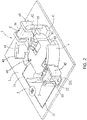
FIG. 2 is a perspective view of the embodiment viewed from another angle; -
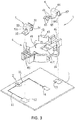
FIG. 3 is an exploded perspective view of the embodiment; -
FIG. 4 is an exploded perspective view of the embodiment viewed from another angle; -
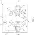
FIG. 5 is a top view of the embodiment; -
FIG. 6 is a sectional view taken along a line VI-VI ofFIG.5 ; -
FIG. 7 is a perspective view illustrating a state that a button battery is placed in the embodiment; and -
FIG. 8 is a view similar toFIG.6 and illustrating the state that the button battery is mounted in the embodiment. - Referring to
FIG. 1 to FIG. 4 ,FIG. 7 andFIG. 8 , a circuit module of an embodiment of the present disclosure comprises acircuit board 1, an indicatingmember 2 and abattery connector 3. Thecircuit board 1 is provided with a firstconductive portion 12, a secondconductive portion 13 and a thirdconductive portion 14. The indicatingmember 2 is electrically connected between the firstconductive portion 12 and the thirdconductive portion 14 of thecircuit board 1. - The
battery connector 3 is provided on thecircuit board 1 so as to electrically connect abutton battery 7, and thebattery connector 3 comprises aninsulating housing 4, apositive terminal 5 and anegative terminal 6. - The
insulating housing 4 comprises abottom wall 41, a plurality ofelastic side walls 42 which respectively connect with thebottom wall 41 and a plurality of protrudingblocks 43, each protrudingblock 43 protrudes from the correspondingelastic side wall 42 at a position close to the top of the correspondingelastic side wall 42, is spaced apart from thebottom wall 41 and faces thebottom wall 41. Thebottom wall 41, the plurality ofelastic side walls 42 and the plurality of protrudingblocks 43 cooperate with each other to define a limitingspace 44 for receiving and fixing thebutton battery 7. Thepositive terminal 5 is fixed to theinsulating housing 4, and comprises apositive contact portion 51 which extends into thelimiting space 44 so as to contact a positive electrode on a side surface of thebutton battery 7 and afirst tail portion 52 which extends out of theinsulating housing 4 and maintains an electrical connection with the firstconductive portion 12 of thecircuit board 1. Thenegative terminal 6 is fixed to theinsulating housing 4, and comprises anegative contact portion 61 which extends into thelimiting space 44 so as to contact a negative electrode on a bottom surface of thebutton battery 7, asecond tail portion 62 which extends out of theinsulating housing 4 and maintains an electrical connection with the secondconductive portion 13 of thecircuit board 1, and aconnection portion 63 which is brought to move by thenegative contact portion 61 so as to electrically connect with the thirdconductive portion 14 of thecircuit board 1 when thebutton battery 7 is received in thelimiting space 44. In the embodiment, when thebutton battery 7 is received in thelimiting space 44, a top surface of thebutton battery 7 abuts against the plurality of protrudingblocks 43, and theconnection portion 63 contacts and electrically connects with the thirdconductive portion 14 of thecircuit board 1, that is, it is ensured that theconnection portion 63 and the thirdconductive portion 14 of thecircuit board 1 establish an electrical connection when thebutton battery 7 is received in thelimiting space 44. Moreover, in the embodiment, thefirst tail portion 52 and thesecond tail portion 62 electrically connect with and maintain electrical connection with the firstconductive portion 12 and the secondconductive portion 13 of thecircuit board 1 by surface mount technology (SMT) respectively, moreover, the firstconductive portion 12, the secondconductive portion 13 and the thirdconductive portion 14 each are a conductive pad, but thefirst tail portion 52 and thesecond tail portion 62 may adjust a connection manner with thecircuit board 1 according to the use requirement, and the firstconductive portion 12 and the secondconductive portion 13 may also correspondingly adjust, for example, when thefirst tail portion 52 and thesecond tail portion 62 each are a pin, the firstconductive portion 12 and the secondconductive portion 13 each correspondingly are a via. - In the embodiment, the
insulating housing 4 further comprises twomounting portions 45 which respectively connect with thebottom wall 41, are spaced apart from each other and face each other, thepositive terminal 5 and thenegative terminal 6 are fixed on the twomounting portions 45 respectively. Thebottom wall 41 of theinsulating housing 4 has a throughgroove 411 which corresponds to theconnection portion 63 of thenegative terminal 6 in position for providing a space for theconnection portion 63 of thenegative terminal 6 to move and contact the thirdconductive portion 14 of thecircuit board 1 so as to establish an electrical connection. Thenegative terminal 6 further comprises afixed portion 64 which is provided on thecorresponding mounting portion 45 and anelastic arm 65 which extends from an end of thefixed portion 64 adjacent to thelimiting space 44. Thesecond tail portion 62 extends from an end of thefixed portion 64 outside thelimiting space 44, theconnection portion 63 is formed at a distal end of theelastic arm 65 and faces toward the throughgroove 411, that is, thesecond tail portion 62 and theconnection portion 63 of thenegative terminal 6 are positioned respectively at two opposite ends. Thenegative contact portion 61 is formed on theelastic arm 65, is adjacent to theconnection portion 63 and faces toward thelimiting space 44. Thepositive terminal 5 further comprises afixed portion 53 which is provided on thecorresponding mounting portion 45 and anelastic arm 54 which extends upwardly from an end of thefixed portion 53 adjacent to thelimiting space 44, thefirst tail portion 52 extends from an end of thefixed portion 53 outside thelimiting space 44, thepositive contact portion 51 is formed on theelastic arm 54 and faces toward thelimiting space 44. In the embodiment, thefixed portion 53 of thepositive terminal 5 and thefixed portion 64 of thenegative terminal 6 each are an inverted U-shape and respectively provided with alatch tab 531 and alatch tab 641 at an opposite side of thelimiting space 44 to respectively latch with thecorresponding mounting portions 45. - Referring to
FIG. 5 andFIG. 6 , when thebutton battery 7 is not mounted on thebattery connector 3, theconnection portion 63 of thenegative terminal 6 is spaced apart from thecircuit board 1 by a certain distance and does not contact thecircuit board 1. Again referring toFIG. 7 andFIG. 8 , when thebutton battery 7 is mounted on the limitingspace 44 and reaches a predetermined position, that is, thebutton battery 7 fully enters into the limitingspace 44 and the top surface of thebutton battery 7 abuts against the plurality of protrudingblocks 43, and thebutton battery 7 can be held by the plurality ofelastic side walls 42 and the plurality of protrudingblocks 43, at this time, thepositive contact portion 51 of thepositive terminal 5 contacts the positive electrode on the side surface of thebutton battery 7 to establish an electrical connection, thenegative contact portion 61 of thenegative terminal 6 contacts the negative electrode on the bottom surface of thebutton battery 7 to establish an electrical connection, and thenegative contact portion 61 is pressed down by thebutton battery 7 to move downwardly, theconnection portion 63 is brought to move by thenegative contact portion 61 to also move downwardly and in turn to contact the thirdconductive portion 14 of thecircuit board 1 to establish an electrical connection, so that the indicatingmember 2 is electrified to generate an indication signal. In other words, when thebutton battery 7 is received in the limitingspace 44, theconnection portion 63 electrically connects with the thirdconductive portion 14 to electrify the indicatingmember 2 to generate the indication signal. That is, when thebutton battery 7 is received in the limitingspace 44, an operative circuit of thebutton battery 7 and an operative circuit of the indicatingmember 2 are electrified at the same time. The indicatingmember 2 may be a light emitting member, such as a light-emitting member (for example LED, bulb), a screen display element (for example liquid crystal display) and the like which can generate for example an optical signal, display character or symbol after electrified. In the embodiment, the indicatingmember 2 electrically connects with the firstconductive portion 12 and the thirdconductive portion 14 via twoconductive wires 11 respectively, theconductive wire 11 may be a trace or a conductive wire directly provided on thecircuit board 1. When thebutton battery 7 is not placed in the limitingspace 44 or does not reach the predetermined position, theconnection portion 63 of thenegative terminal 6 does not contact the thirdconductive portion 14 of thecircuit board 1, so that the operative circuit of the indicatingmember 2 is interrupted; when thebutton battery 7 is placed in the limitingspace 44 and reaches the predetermined position, theconnection portion 63 of thenegative terminal 6 contacts the thirdconductive portion 14 of thecircuit board 1 to establish an electrical connection, so that the operative circuit of the indicatingmember 2 is electrified and the indicatingmember 2 generates an indication signal. If thebutton battery 7 does not reach the predetermined position when mounted, the indicatingmember 2 does not generate any indication signal, which can remind a user that thebutton battery 7 is not placed to reach a predetermined position. In this way, whether thebutton battery 7 is mounted to reach the predetermined position or not can be detected and provided for a user for identification, so that it avoids thebutton battery 7 not being mounted to reach the predetermined position to produce the risk of poor electrical contact or electrical interruption. Moreover, when thebutton battery 7 is received in the limitingspace 44, thenegative contact portion 61 of thenegative terminal 6 can obtain support by that theconnection portion 63 abuts against thecircuit board 1 to make a normal force of thenegative contact portion 61 contacting thebutton battery 7 increased, and in turn the contact stability can be maintained, that is, thebutton battery 7 electrically connects with thenegative terminal 6 stably. - In conclusion, when the
button battery 7 is received in the limitingspace 44, theconnection portion 63 of thenegative terminal 6 electrically connects with the thirdconductive portion 14 of thecircuit board 1 to electrify the indicatingmember 2 and in turn the indicatingmember 2 generates an indication signal, so that whether thebutton battery 7 is mounted to reach the predetermined position or not can be detected and provided for a user for identification, so that it avoids thebutton battery 7 not being mounted to reach the predetermined position to produce the risk of poor electrical contact or electrical interruption. And, when thebutton battery 7 is received in the limitingspace 44, thenegative contact portion 61 of thenegative terminal 6 can obtain support by that theconnection portion 63 abuts against thecircuit board 1 to make a normal force of thenegative contact portion 61 contacting thebutton battery 7 increased, and in turn the contact stability can be maintained, that is, thebutton battery 7 electrically connects with thenegative terminal 6 stably. - The above described contents are only the embodiments of the present disclosure, which cannot limit the scope of the implementation of the present disclosure, namely simple equivalent variations and modifications made according to the claims and the content of the present disclosure are still fallen within the scope of the present disclosure.
- A battery connector is provided which is used to electrically connect a button battery. The connector has an insulating housing and positive and negative terminals. The housing has a limiting space for receiving and fixing the battery. The positive terminal has a positive contact portion which extends into the space and a first tail portion which maintains an electrical connection with a circuit board. The negative terminal has a negative contact portion which extends into the space so as to contact a negative electrode on a bottom surface of the battery, a second tail portion which maintains an electrical connection with the board, and a connection portion which is brought to move by the negative contact portion so as to electrically connect with the board when the battery is received in the space. The battery connector can be provided as part of a circuit module having an indicating member.
Claims (15)
- A battery connector, for being mounted on a circuit board to electrically connect a button battery, the circuit board being provided with a first conductive portion, a second conductive portion and a third conductive portion, and an indicating member being electrically connected between the first conductive portion and the third conductive portion, the battery connector comprising:an insulating housing comprising a bottom wall, a plurality of elastic side walls which respectively connect with the bottom wall and a plurality of protruding blocks, each protruding block protruding from the corresponding elastic side wall at a position adjacent to the top of the corresponding elastic side wall, being spaced apart from the bottom wall and facing the bottom wall, the bottom wall, the plurality of elastic side walls and the plurality of protruding blocks cooperating with each other to define a limiting space for receiving and fixing the button battery;a positive terminal fixed to the insulating housing, the positive terminal comprising a positive contact portion which extends into the limiting space so as to contact a positive electrode on a side surface of the button battery and a first tail portion which extends out of the insulating housing so as to maintain an electrical connection with the first conductive portion of the circuit board; anda negative terminal fixed to the insulating housing, the negative terminal comprising a negative contact portion which extends into the limiting space so as to contact a negative electrode on a bottom surface of the button battery, a second tail portion which extends out of the insulating housing so as to maintain an electrical connection with the second conductive portion of the circuit board and a connection portion which is brought to move by the negative contact portion so as to electrically connect with the third conductive portion when the button battery is received in the limiting space, the indicating member being electrified to generate an indication signal by that the connection portion electrically connects with the third conductive portion.
- The battery connector according to Claim 1, wherein when the button battery is received in the limiting space, a top surface of the button battery abuts against the plurality of protruding blocks and the connection portion contacts and electrically connects with the circuit board.
- The battery connector according to Claim 1 or 2, wherein the second tail portion and the connection portion of the negative terminal are positioned at two opposite ends respectively.
- The battery connector according to one of Claims 1-3, wherein the insulating housing further comprises two mounting portions which respectively connect with the bottom wall, are spaced apart from each other and face each other, and the positive terminal and the negative terminal are fixed on the two mounting portions respectively.
- The battery connector according to one of Claims 1-4, wherein the bottom wall of the insulating housing has a through groove which corresponds to the connection portion of the negative terminal in position for providing a space for the connection portion of the negative terminal to move and contact the third conductive portion of the circuit board so as to establish an electrical connection.
- The battery connector according to Claim 5, wherein the negative terminal further comprises a fixed portion which is provided on the corresponding mounting portion and an elastic arm which extends from an end of the fixed portion adjacent to the limiting space, the second tail portion extends from an end of the fixed portion outside the limiting space, the connection portion is formed at a distal end of the elastic arm and faces toward the through groove, the negative contact portion is formed on the elastic arm, is adjacent to the connection portion and faces toward the limiting space.
- A circuit module, comprising:a circuit board provided with a first conductive portion, a second conductive portion and a third conductive portion;an indicating member electrically connected between the first conductive portion and the third conductive portion of the circuit board; anda battery connector mounted on the circuit board to electrically connect a button battery, and comprising:an insulating housing comprising a bottom wall, a plurality of elastic side walls which respectively connect with the bottom wall and a plurality of protruding blocks, each protruding block protruding from the corresponding elastic side wall at a position adjacent to the top of the corresponding elastic side wall, being spaced apart from the bottom wall and facing the bottom wall, the bottom wall, the plurality of elastic side walls and the plurality of protruding blocks cooperating with each other to define a limiting space for receiving and fixing the button battery;a positive terminal fixed to the insulating housing, the positive terminal comprising a positive contact portion which extends into the limiting space so as to contact a positive electrode on a side surface of the button battery and a first tail portion which extends out of the insulating housing so as to maintain an electrical connection with the first conductive portion of the circuit board; anda negative terminal fixed to the insulating housing, the negative terminal comprising a negative contact portion which extends into the limiting space so as to contact a negative electrode on a bottom surface of the button battery, a second tail portion which extends out of the insulating housing so as to maintain an electrical connection with the second conductive portion of the circuit board and a connection portion which is brought to move by the negative contact portion so as to electrically connect with the third conductive portion when the button battery is received in the limiting space, the indicating member being electrified to generate an indication signal by that the connection portion electrically connects with the third conductive portion.
- The circuit module according to Claim 7, wherein when the button battery is received in the limiting space, a top surface of the button battery abuts against the plurality of protruding blocks and the connection portion contacts and electrically connects with the circuit board.
- The circuit module according to Claim 7 or 8, wherein the second tail portion and the connection portion of the negative terminal are positioned at two opposite ends respectively.
- The circuit module according to Claim 9, wherein the insulating housing further comprises two mounting portions which respectively connect with the bottom wall, are spaced apart from each other and face each other, and the positive terminal and the negative terminal are fixed on the two mounting portions respectively.
- The circuit module according to one of Claims 7-10, wherein the bottom wall of the insulating housing has a through groove which corresponds to the connection portion of the negative terminal in position for providing a space for the connection portion of the negative terminal to move and contact the third conductive portion of the circuit board so as to establish an electrical connection.
- The circuit module according to Claim 11, wherein the negative terminal further comprises a fixed portion which is provided on the corresponding mounting portion and an elastic arm which extends from an end of the fixed portion adjacent to the limiting space, the second tail portion extends from an end of the fixed portion outside the limiting space, the connection portion is formed at a distal end of the elastic arm and faces toward the through groove, the negative contact portion is formed on the elastic arm, is adjacent to the connection portion and faces toward the limiting space.
- The circuit module according to one of Claims 7-12, wherein the indicating member is a light emitting member.
- The circuit module according to one of Claims 7-13, wherein the indicating member is a screen display element.
- The circuit module according to one of Claims 7-14, wherein the indicating component electrically connects with the first conductive portion and the third conductive portion via two conductive wires respectively.
Applications Claiming Priority (1)
| Application Number | Priority Date | Filing Date | Title |
|---|---|---|---|
| CN201521080788.8U CN205248327U (en) | 2015-12-22 | 2015-12-22 | Battery connector and circuit module |
Publications (2)
| Publication Number | Publication Date |
|---|---|
| EP3185337A1 true EP3185337A1 (en) | 2017-06-28 |
| EP3185337B1 EP3185337B1 (en) | 2019-03-27 |
Family
ID=55947403
Family Applications (1)
| Application Number | Title | Priority Date | Filing Date |
|---|---|---|---|
| EP16205564.4A Not-in-force EP3185337B1 (en) | 2015-12-22 | 2016-12-20 | Battery connector and circuit module |
Country Status (4)
| Country | Link |
|---|---|
| US (1) | US9748719B2 (en) |
| EP (1) | EP3185337B1 (en) |
| CN (1) | CN205248327U (en) |
| TW (1) | TWM526765U (en) |
Cited By (2)
| Publication number | Priority date | Publication date | Assignee | Title |
|---|---|---|---|---|
| EP3806235A1 (en) * | 2019-10-08 | 2021-04-14 | Huf Hülsbeck & Fürst GmbH & Co. KG | Battery contacting assembly and method for producing the battery contacting assembly |
| WO2023228056A1 (en) * | 2022-05-26 | 2023-11-30 | 3M Innovative Properties Company | Devices with planarized connections to coin cell battery |
Families Citing this family (10)
| Publication number | Priority date | Publication date | Assignee | Title |
|---|---|---|---|---|
| CN107403899B (en) * | 2016-05-20 | 2020-05-08 | 莫列斯有限公司 | Battery connection module |
| CN107719139A (en) * | 2016-08-10 | 2018-02-23 | 深圳市沃特玛电池有限公司 | Electric automobile chassis device |
| JP6741530B2 (en) * | 2016-09-12 | 2020-08-19 | アルプスアルパイン株式会社 | Electronics |
| JP6935088B2 (en) * | 2017-08-25 | 2021-09-15 | 日本圧着端子製造株式会社 | Electrical connector |
| CN108461942A (en) * | 2017-12-29 | 2018-08-28 | 杭州华为数字技术有限公司 | Battery tray |
| US10894578B2 (en) * | 2018-01-11 | 2021-01-19 | Sram, Llc | Electronic shift control device for a bicycle derailleur |
| CN208507805U (en) * | 2018-08-15 | 2019-02-15 | 宁德时代新能源科技股份有限公司 | Connector and battery product |
| CN114487869A (en) * | 2020-11-12 | 2022-05-13 | 邑流微测股份有限公司 | Button cell testing device |
| CN118486988B (en) * | 2024-07-08 | 2024-09-17 | 江苏新华陵汽车电器有限公司 | Automobile ignition key detection system |
| CN119587015B (en) * | 2024-11-07 | 2025-11-25 | 深圳希沃康医疗科技有限公司 | Disposable medical devices and their battery connection methods |
Citations (3)
| Publication number | Priority date | Publication date | Assignee | Title |
|---|---|---|---|---|
| CN101097998A (en) | 2006-06-29 | 2008-01-02 | 意力速电子工业株式会社 | Battery holder |
| US20080102691A1 (en) * | 2006-10-26 | 2008-05-01 | Cooper Technologies Company | Low-profile power supply terminal assembly |
| CN204349003U (en) * | 2015-01-28 | 2015-05-20 | 上海莫仕连接器有限公司 | Battery connector |
Family Cites Families (2)
| Publication number | Priority date | Publication date | Assignee | Title |
|---|---|---|---|---|
| CN201113124Y (en) | 2007-07-10 | 2008-09-10 | 富士康(昆山)电脑接插件有限公司 | battery connector |
| CN103682189B (en) | 2012-08-31 | 2016-01-20 | 青岛橡胶谷知识产权有限公司 | Button cell seat |
-
2015
- 2015-12-22 CN CN201521080788.8U patent/CN205248327U/en not_active Expired - Fee Related
-
2016
- 2016-01-22 TW TW105200978U patent/TWM526765U/en not_active IP Right Cessation
- 2016-11-10 US US15/348,399 patent/US9748719B2/en not_active Expired - Fee Related
- 2016-12-20 EP EP16205564.4A patent/EP3185337B1/en not_active Not-in-force
Patent Citations (3)
| Publication number | Priority date | Publication date | Assignee | Title |
|---|---|---|---|---|
| CN101097998A (en) | 2006-06-29 | 2008-01-02 | 意力速电子工业株式会社 | Battery holder |
| US20080102691A1 (en) * | 2006-10-26 | 2008-05-01 | Cooper Technologies Company | Low-profile power supply terminal assembly |
| CN204349003U (en) * | 2015-01-28 | 2015-05-20 | 上海莫仕连接器有限公司 | Battery connector |
Cited By (2)
| Publication number | Priority date | Publication date | Assignee | Title |
|---|---|---|---|---|
| EP3806235A1 (en) * | 2019-10-08 | 2021-04-14 | Huf Hülsbeck & Fürst GmbH & Co. KG | Battery contacting assembly and method for producing the battery contacting assembly |
| WO2023228056A1 (en) * | 2022-05-26 | 2023-11-30 | 3M Innovative Properties Company | Devices with planarized connections to coin cell battery |
Also Published As
| Publication number | Publication date |
|---|---|
| US20170179662A1 (en) | 2017-06-22 |
| EP3185337B1 (en) | 2019-03-27 |
| US9748719B2 (en) | 2017-08-29 |
| TWM526765U (en) | 2016-08-01 |
| CN205248327U (en) | 2016-05-18 |
Similar Documents
| Publication | Publication Date | Title |
|---|---|---|
| EP3185337B1 (en) | Battery connector and circuit module | |
| US10707606B2 (en) | Electrical connector | |
| US9859667B2 (en) | Cable connector assembly having an illumination function | |
| US7794285B1 (en) | Audio jack connector | |
| US9466921B2 (en) | Linear conductor connection terminal | |
| US9748706B2 (en) | Electrical connector having improved detective member | |
| US10079444B2 (en) | Electrical connector having conductive balls | |
| JP2000147545A (en) | Display mounting connection device | |
| US10062997B2 (en) | Electrical connector having improved contacts | |
| US20120045946A1 (en) | Socket connector having suitable receiving solder lead from ic package | |
| JP6564286B2 (en) | Plug connector, plug connector unit, and connector device | |
| US20110294365A1 (en) | Elastic electrical contact | |
| US20170062959A1 (en) | Circuit board passage terminal | |
| US7287988B1 (en) | Board-to-board connector | |
| US7258571B1 (en) | Battery connector with retaining board | |
| KR101693024B1 (en) | A signal transfer assembly for sensor | |
| US6817906B2 (en) | Electrical connector having indicating function | |
| US10591150B2 (en) | Integrated electrical connector device structure of LED light | |
| JP6681655B2 (en) | Coaxial connector | |
| KR101850978B1 (en) | Wire connecting unt and led module comprising the same | |
| JP3147997U (en) | Connector terminals and connectors | |
| KR101344935B1 (en) | contact for connector | |
| JP4563250B2 (en) | Connector, receptacle connector, and portable wireless terminal or small electronic device | |
| JP3203673U (en) | Automatic switch device for flashlight | |
| CN201868598U (en) | Electric connector |
Legal Events
| Date | Code | Title | Description |
|---|---|---|---|
| PUAI | Public reference made under article 153(3) epc to a published international application that has entered the european phase |
Free format text: ORIGINAL CODE: 0009012 |
|
| STAA | Information on the status of an ep patent application or granted ep patent |
Free format text: STATUS: THE APPLICATION HAS BEEN PUBLISHED |
|
| AK | Designated contracting states |
Kind code of ref document: A1 Designated state(s): AL AT BE BG CH CY CZ DE DK EE ES FI FR GB GR HR HU IE IS IT LI LT LU LV MC MK MT NL NO PL PT RO RS SE SI SK SM TR |
|
| AX | Request for extension of the european patent |
Extension state: BA ME |
|
| STAA | Information on the status of an ep patent application or granted ep patent |
Free format text: STATUS: REQUEST FOR EXAMINATION WAS MADE |
|
| 17P | Request for examination filed |
Effective date: 20171121 |
|
| RBV | Designated contracting states (corrected) |
Designated state(s): AL AT BE BG CH CY CZ DE DK EE ES FI FR GB GR HR HU IE IS IT LI LT LU LV MC MK MT NL NO PL PT RO RS SE SI SK SM TR |
|
| GRAP | Despatch of communication of intention to grant a patent |
Free format text: ORIGINAL CODE: EPIDOSNIGR1 |
|
| STAA | Information on the status of an ep patent application or granted ep patent |
Free format text: STATUS: GRANT OF PATENT IS INTENDED |
|
| RIC1 | Information provided on ipc code assigned before grant |
Ipc: H01M 10/42 20060101ALI20180926BHEP Ipc: H01M 2/10 20060101AFI20180926BHEP Ipc: H01R 103/00 20060101ALI20180926BHEP Ipc: H01M 2/20 20060101ALI20180926BHEP Ipc: H01M 10/48 20060101ALI20180926BHEP |
|
| INTG | Intention to grant announced |
Effective date: 20181012 |
|
| GRAS | Grant fee paid |
Free format text: ORIGINAL CODE: EPIDOSNIGR3 |
|
| GRAA | (expected) grant |
Free format text: ORIGINAL CODE: 0009210 |
|
| STAA | Information on the status of an ep patent application or granted ep patent |
Free format text: STATUS: THE PATENT HAS BEEN GRANTED |
|
| AK | Designated contracting states |
Kind code of ref document: B1 Designated state(s): AL AT BE BG CH CY CZ DE DK EE ES FI FR GB GR HR HU IE IS IT LI LT LU LV MC MK MT NL NO PL PT RO RS SE SI SK SM TR |
|
| REG | Reference to a national code |
Ref country code: GB Ref legal event code: FG4D |
|
| REG | Reference to a national code |
Ref country code: CH Ref legal event code: EP |
|
| REG | Reference to a national code |
Ref country code: AT Ref legal event code: REF Ref document number: 1114101 Country of ref document: AT Kind code of ref document: T Effective date: 20190415 |
|
| REG | Reference to a national code |
Ref country code: IE Ref legal event code: FG4D |
|
| REG | Reference to a national code |
Ref country code: DE Ref legal event code: R096 Ref document number: 602016011536 Country of ref document: DE |
|
| PG25 | Lapsed in a contracting state [announced via postgrant information from national office to epo] |
Ref country code: SE Free format text: LAPSE BECAUSE OF FAILURE TO SUBMIT A TRANSLATION OF THE DESCRIPTION OR TO PAY THE FEE WITHIN THE PRESCRIBED TIME-LIMIT Effective date: 20190327 Ref country code: NO Free format text: LAPSE BECAUSE OF FAILURE TO SUBMIT A TRANSLATION OF THE DESCRIPTION OR TO PAY THE FEE WITHIN THE PRESCRIBED TIME-LIMIT Effective date: 20190627 Ref country code: FI Free format text: LAPSE BECAUSE OF FAILURE TO SUBMIT A TRANSLATION OF THE DESCRIPTION OR TO PAY THE FEE WITHIN THE PRESCRIBED TIME-LIMIT Effective date: 20190327 Ref country code: LT Free format text: LAPSE BECAUSE OF FAILURE TO SUBMIT A TRANSLATION OF THE DESCRIPTION OR TO PAY THE FEE WITHIN THE PRESCRIBED TIME-LIMIT Effective date: 20190327 |
|
| REG | Reference to a national code |
Ref country code: NL Ref legal event code: MP Effective date: 20190327 |
|
| PG25 | Lapsed in a contracting state [announced via postgrant information from national office to epo] |
Ref country code: BG Free format text: LAPSE BECAUSE OF FAILURE TO SUBMIT A TRANSLATION OF THE DESCRIPTION OR TO PAY THE FEE WITHIN THE PRESCRIBED TIME-LIMIT Effective date: 20190627 Ref country code: GR Free format text: LAPSE BECAUSE OF FAILURE TO SUBMIT A TRANSLATION OF THE DESCRIPTION OR TO PAY THE FEE WITHIN THE PRESCRIBED TIME-LIMIT Effective date: 20190628 Ref country code: HR Free format text: LAPSE BECAUSE OF FAILURE TO SUBMIT A TRANSLATION OF THE DESCRIPTION OR TO PAY THE FEE WITHIN THE PRESCRIBED TIME-LIMIT Effective date: 20190327 Ref country code: LV Free format text: LAPSE BECAUSE OF FAILURE TO SUBMIT A TRANSLATION OF THE DESCRIPTION OR TO PAY THE FEE WITHIN THE PRESCRIBED TIME-LIMIT Effective date: 20190327 Ref country code: NL Free format text: LAPSE BECAUSE OF FAILURE TO SUBMIT A TRANSLATION OF THE DESCRIPTION OR TO PAY THE FEE WITHIN THE PRESCRIBED TIME-LIMIT Effective date: 20190327 Ref country code: RS Free format text: LAPSE BECAUSE OF FAILURE TO SUBMIT A TRANSLATION OF THE DESCRIPTION OR TO PAY THE FEE WITHIN THE PRESCRIBED TIME-LIMIT Effective date: 20190327 |
|
| REG | Reference to a national code |
Ref country code: AT Ref legal event code: MK05 Ref document number: 1114101 Country of ref document: AT Kind code of ref document: T Effective date: 20190327 |
|
| PG25 | Lapsed in a contracting state [announced via postgrant information from national office to epo] |
Ref country code: IT Free format text: LAPSE BECAUSE OF FAILURE TO SUBMIT A TRANSLATION OF THE DESCRIPTION OR TO PAY THE FEE WITHIN THE PRESCRIBED TIME-LIMIT Effective date: 20190327 Ref country code: ES Free format text: LAPSE BECAUSE OF FAILURE TO SUBMIT A TRANSLATION OF THE DESCRIPTION OR TO PAY THE FEE WITHIN THE PRESCRIBED TIME-LIMIT Effective date: 20190327 Ref country code: CZ Free format text: LAPSE BECAUSE OF FAILURE TO SUBMIT A TRANSLATION OF THE DESCRIPTION OR TO PAY THE FEE WITHIN THE PRESCRIBED TIME-LIMIT Effective date: 20190327 Ref country code: RO Free format text: LAPSE BECAUSE OF FAILURE TO SUBMIT A TRANSLATION OF THE DESCRIPTION OR TO PAY THE FEE WITHIN THE PRESCRIBED TIME-LIMIT Effective date: 20190327 Ref country code: EE Free format text: LAPSE BECAUSE OF FAILURE TO SUBMIT A TRANSLATION OF THE DESCRIPTION OR TO PAY THE FEE WITHIN THE PRESCRIBED TIME-LIMIT Effective date: 20190327 Ref country code: AL Free format text: LAPSE BECAUSE OF FAILURE TO SUBMIT A TRANSLATION OF THE DESCRIPTION OR TO PAY THE FEE WITHIN THE PRESCRIBED TIME-LIMIT Effective date: 20190327 Ref country code: SK Free format text: LAPSE BECAUSE OF FAILURE TO SUBMIT A TRANSLATION OF THE DESCRIPTION OR TO PAY THE FEE WITHIN THE PRESCRIBED TIME-LIMIT Effective date: 20190327 Ref country code: PT Free format text: LAPSE BECAUSE OF FAILURE TO SUBMIT A TRANSLATION OF THE DESCRIPTION OR TO PAY THE FEE WITHIN THE PRESCRIBED TIME-LIMIT Effective date: 20190727 |
|
| PG25 | Lapsed in a contracting state [announced via postgrant information from national office to epo] |
Ref country code: PL Free format text: LAPSE BECAUSE OF FAILURE TO SUBMIT A TRANSLATION OF THE DESCRIPTION OR TO PAY THE FEE WITHIN THE PRESCRIBED TIME-LIMIT Effective date: 20190327 Ref country code: SM Free format text: LAPSE BECAUSE OF FAILURE TO SUBMIT A TRANSLATION OF THE DESCRIPTION OR TO PAY THE FEE WITHIN THE PRESCRIBED TIME-LIMIT Effective date: 20190327 |
|
| PG25 | Lapsed in a contracting state [announced via postgrant information from national office to epo] |
Ref country code: AT Free format text: LAPSE BECAUSE OF FAILURE TO SUBMIT A TRANSLATION OF THE DESCRIPTION OR TO PAY THE FEE WITHIN THE PRESCRIBED TIME-LIMIT Effective date: 20190327 Ref country code: IS Free format text: LAPSE BECAUSE OF FAILURE TO SUBMIT A TRANSLATION OF THE DESCRIPTION OR TO PAY THE FEE WITHIN THE PRESCRIBED TIME-LIMIT Effective date: 20190727 |
|
| REG | Reference to a national code |
Ref country code: DE Ref legal event code: R097 Ref document number: 602016011536 Country of ref document: DE |
|
| PG25 | Lapsed in a contracting state [announced via postgrant information from national office to epo] |
Ref country code: DK Free format text: LAPSE BECAUSE OF FAILURE TO SUBMIT A TRANSLATION OF THE DESCRIPTION OR TO PAY THE FEE WITHIN THE PRESCRIBED TIME-LIMIT Effective date: 20190327 |
|
| PGFP | Annual fee paid to national office [announced via postgrant information from national office to epo] |
Ref country code: DE Payment date: 20191210 Year of fee payment: 4 |
|
| PLBE | No opposition filed within time limit |
Free format text: ORIGINAL CODE: 0009261 |
|
| STAA | Information on the status of an ep patent application or granted ep patent |
Free format text: STATUS: NO OPPOSITION FILED WITHIN TIME LIMIT |
|
| PG25 | Lapsed in a contracting state [announced via postgrant information from national office to epo] |
Ref country code: SI Free format text: LAPSE BECAUSE OF FAILURE TO SUBMIT A TRANSLATION OF THE DESCRIPTION OR TO PAY THE FEE WITHIN THE PRESCRIBED TIME-LIMIT Effective date: 20190327 |
|
| 26N | No opposition filed |
Effective date: 20200103 |
|
| PG25 | Lapsed in a contracting state [announced via postgrant information from national office to epo] |
Ref country code: TR Free format text: LAPSE BECAUSE OF FAILURE TO SUBMIT A TRANSLATION OF THE DESCRIPTION OR TO PAY THE FEE WITHIN THE PRESCRIBED TIME-LIMIT Effective date: 20190327 |
|
| REG | Reference to a national code |
Ref country code: CH Ref legal event code: PL |
|
| REG | Reference to a national code |
Ref country code: BE Ref legal event code: MM Effective date: 20191231 |
|
| PG25 | Lapsed in a contracting state [announced via postgrant information from national office to epo] |
Ref country code: MC Free format text: LAPSE BECAUSE OF FAILURE TO SUBMIT A TRANSLATION OF THE DESCRIPTION OR TO PAY THE FEE WITHIN THE PRESCRIBED TIME-LIMIT Effective date: 20190327 |
|
| PG25 | Lapsed in a contracting state [announced via postgrant information from national office to epo] |
Ref country code: LU Free format text: LAPSE BECAUSE OF NON-PAYMENT OF DUE FEES Effective date: 20191220 Ref country code: FR Free format text: LAPSE BECAUSE OF NON-PAYMENT OF DUE FEES Effective date: 20191231 Ref country code: IE Free format text: LAPSE BECAUSE OF NON-PAYMENT OF DUE FEES Effective date: 20191220 |
|
| REG | Reference to a national code |
Ref country code: DE Ref legal event code: R079 Ref document number: 602016011536 Country of ref document: DE Free format text: PREVIOUS MAIN CLASS: H01M0002100000 Ipc: H01M0050200000 |
|
| PG25 | Lapsed in a contracting state [announced via postgrant information from national office to epo] |
Ref country code: BE Free format text: LAPSE BECAUSE OF NON-PAYMENT OF DUE FEES Effective date: 20191231 Ref country code: LI Free format text: LAPSE BECAUSE OF NON-PAYMENT OF DUE FEES Effective date: 20191231 Ref country code: CH Free format text: LAPSE BECAUSE OF NON-PAYMENT OF DUE FEES Effective date: 20191231 |
|
| PG25 | Lapsed in a contracting state [announced via postgrant information from national office to epo] |
Ref country code: CY Free format text: LAPSE BECAUSE OF FAILURE TO SUBMIT A TRANSLATION OF THE DESCRIPTION OR TO PAY THE FEE WITHIN THE PRESCRIBED TIME-LIMIT Effective date: 20190327 |
|
| REG | Reference to a national code |
Ref country code: DE Ref legal event code: R119 Ref document number: 602016011536 Country of ref document: DE |
|
| PG25 | Lapsed in a contracting state [announced via postgrant information from national office to epo] |
Ref country code: MT Free format text: LAPSE BECAUSE OF FAILURE TO SUBMIT A TRANSLATION OF THE DESCRIPTION OR TO PAY THE FEE WITHIN THE PRESCRIBED TIME-LIMIT Effective date: 20190327 Ref country code: HU Free format text: LAPSE BECAUSE OF FAILURE TO SUBMIT A TRANSLATION OF THE DESCRIPTION OR TO PAY THE FEE WITHIN THE PRESCRIBED TIME-LIMIT; INVALID AB INITIO Effective date: 20161220 |
|
| GBPC | Gb: european patent ceased through non-payment of renewal fee |
Effective date: 20201220 |
|
| PG25 | Lapsed in a contracting state [announced via postgrant information from national office to epo] |
Ref country code: GB Free format text: LAPSE BECAUSE OF NON-PAYMENT OF DUE FEES Effective date: 20201220 Ref country code: DE Free format text: LAPSE BECAUSE OF NON-PAYMENT OF DUE FEES Effective date: 20210701 |
|
| PG25 | Lapsed in a contracting state [announced via postgrant information from national office to epo] |
Ref country code: MK Free format text: LAPSE BECAUSE OF FAILURE TO SUBMIT A TRANSLATION OF THE DESCRIPTION OR TO PAY THE FEE WITHIN THE PRESCRIBED TIME-LIMIT Effective date: 20190327 |