EP3185244A1 - Voice activation system - Google Patents
Voice activation system Download PDFInfo
- Publication number
- EP3185244A1 EP3185244A1 EP15201872.7A EP15201872A EP3185244A1 EP 3185244 A1 EP3185244 A1 EP 3185244A1 EP 15201872 A EP15201872 A EP 15201872A EP 3185244 A1 EP3185244 A1 EP 3185244A1
- Authority
- EP
- European Patent Office
- Prior art keywords
- signal
- detector
- voice
- speech
- microphone
- Prior art date
- Legal status (The legal status is an assumption and is not a legal conclusion. Google has not performed a legal analysis and makes no representation as to the accuracy of the status listed.)
- Granted
Links
Images


Classifications
-
- G—PHYSICS
- G10—MUSICAL INSTRUMENTS; ACOUSTICS
- G10L—SPEECH ANALYSIS TECHNIQUES OR SPEECH SYNTHESIS; SPEECH RECOGNITION; SPEECH OR VOICE PROCESSING TECHNIQUES; SPEECH OR AUDIO CODING OR DECODING
- G10L25/00—Speech or voice analysis techniques not restricted to a single one of groups G10L15/00 - G10L21/00
- G10L25/78—Detection of presence or absence of voice signals
-
- G—PHYSICS
- G06—COMPUTING OR CALCULATING; COUNTING
- G06F—ELECTRIC DIGITAL DATA PROCESSING
- G06F1/00—Details not covered by groups G06F3/00 - G06F13/00 and G06F21/00
- G06F1/26—Power supply means, e.g. regulation thereof
- G06F1/32—Means for saving power
- G06F1/3203—Power management, i.e. event-based initiation of a power-saving mode
- G06F1/3234—Power saving characterised by the action undertaken
- G06F1/3287—Power saving characterised by the action undertaken by switching off individual functional units in the computer system
-
- G—PHYSICS
- G10—MUSICAL INSTRUMENTS; ACOUSTICS
- G10L—SPEECH ANALYSIS TECHNIQUES OR SPEECH SYNTHESIS; SPEECH RECOGNITION; SPEECH OR VOICE PROCESSING TECHNIQUES; SPEECH OR AUDIO CODING OR DECODING
- G10L15/00—Speech recognition
- G10L15/08—Speech classification or search
-
- G—PHYSICS
- G10—MUSICAL INSTRUMENTS; ACOUSTICS
- G10L—SPEECH ANALYSIS TECHNIQUES OR SPEECH SYNTHESIS; SPEECH RECOGNITION; SPEECH OR VOICE PROCESSING TECHNIQUES; SPEECH OR AUDIO CODING OR DECODING
- G10L15/00—Speech recognition
- G10L15/20—Speech recognition techniques specially adapted for robustness in adverse environments, e.g. in noise, of stress induced speech
-
- G—PHYSICS
- G10—MUSICAL INSTRUMENTS; ACOUSTICS
- G10L—SPEECH ANALYSIS TECHNIQUES OR SPEECH SYNTHESIS; SPEECH RECOGNITION; SPEECH OR VOICE PROCESSING TECHNIQUES; SPEECH OR AUDIO CODING OR DECODING
- G10L15/00—Speech recognition
- G10L15/22—Procedures used during a speech recognition process, e.g. man-machine dialogue
-
- G—PHYSICS
- G10—MUSICAL INSTRUMENTS; ACOUSTICS
- G10L—SPEECH ANALYSIS TECHNIQUES OR SPEECH SYNTHESIS; SPEECH RECOGNITION; SPEECH OR VOICE PROCESSING TECHNIQUES; SPEECH OR AUDIO CODING OR DECODING
- G10L15/00—Speech recognition
- G10L15/28—Constructional details of speech recognition systems
- G10L15/32—Multiple recognisers used in sequence or in parallel; Score combination systems therefor, e.g. voting systems
-
- G—PHYSICS
- G10—MUSICAL INSTRUMENTS; ACOUSTICS
- G10L—SPEECH ANALYSIS TECHNIQUES OR SPEECH SYNTHESIS; SPEECH RECOGNITION; SPEECH OR VOICE PROCESSING TECHNIQUES; SPEECH OR AUDIO CODING OR DECODING
- G10L25/00—Speech or voice analysis techniques not restricted to a single one of groups G10L15/00 - G10L21/00
- G10L25/78—Detection of presence or absence of voice signals
- G10L25/84—Detection of presence or absence of voice signals for discriminating voice from noise
-
- H—ELECTRICITY
- H04—ELECTRIC COMMUNICATION TECHNIQUE
- H04R—LOUDSPEAKERS, MICROPHONES, GRAMOPHONE PICK-UPS OR LIKE ACOUSTIC ELECTROMECHANICAL TRANSDUCERS; ELECTRIC HEARING AIDS; PUBLIC ADDRESS SYSTEMS
- H04R3/00—Circuits for transducers
- H04R3/005—Circuits for transducers for combining the signals of two or more microphones
-
- G—PHYSICS
- G10—MUSICAL INSTRUMENTS; ACOUSTICS
- G10L—SPEECH ANALYSIS TECHNIQUES OR SPEECH SYNTHESIS; SPEECH RECOGNITION; SPEECH OR VOICE PROCESSING TECHNIQUES; SPEECH OR AUDIO CODING OR DECODING
- G10L15/00—Speech recognition
- G10L15/08—Speech classification or search
- G10L2015/088—Word spotting
-
- H—ELECTRICITY
- H04—ELECTRIC COMMUNICATION TECHNIQUE
- H04R—LOUDSPEAKERS, MICROPHONES, GRAMOPHONE PICK-UPS OR LIKE ACOUSTIC ELECTROMECHANICAL TRANSDUCERS; ELECTRIC HEARING AIDS; PUBLIC ADDRESS SYSTEMS
- H04R2400/00—Loudspeakers
- H04R2400/01—Transducers used as a loudspeaker to generate sound aswell as a microphone to detect sound
-
- H—ELECTRICITY
- H04—ELECTRIC COMMUNICATION TECHNIQUE
- H04R—LOUDSPEAKERS, MICROPHONES, GRAMOPHONE PICK-UPS OR LIKE ACOUSTIC ELECTROMECHANICAL TRANSDUCERS; ELECTRIC HEARING AIDS; PUBLIC ADDRESS SYSTEMS
- H04R2499/00—Aspects covered by H04R or H04S not otherwise provided for in their subgroups
- H04R2499/10—General applications
- H04R2499/11—Transducers incorporated or for use in hand-held devices, e.g. mobile phones, PDA's, camera's
Definitions
- This disclosure relates to a voice activation system for a mobile audio device.
- Mobile audio devices such as mobile phones are getting smarter and are more and more equipped with "always-on" functionalities, which continuously sense the environment to perform anticipative actions such as device wake-up, voice keyword detection.
- Always-on functionalities have very low power requirements, which may be typically lower than 1 milliwatt (mW), and usually make use of dedicated sensors and low power hardware components implemented as integrated circuits in order to function independently from the main processor. This is particularly the case for wearable mobile audio devices such as active earbuds or watches.
- voice activation the main processor is only woken up by the voice activation system if a dedicated keyword has been recognized.
- a multi-stage detection is usually applied.
- a voice activation system for a mobile audio device comprising a speaker and a microphone
- the voice activation system comprising: a first voice activity detector having a first detector input for receiving a first signal from a microphone and a first detector output; a second voice activity detector having a second detector input for receiving a second signal from a speaker and a second detector output; a voice detector output coupled to the first detector output and the second detector output; wherein the first detector and the second detector are operable to generate an output signal in response to a candidate speech signal received on the respective detector inputs and wherein the voice activation system is configured to generate a voice detector output signal when at least one of the first detector output and the second detector output indicate that speech has been detected.
- the voice activity detector may be configured to generate a voice detector output signal when both the first detector output and the second detector output indicate that speech has been detected.
- the voice activation system may have a first power mode and a second power mode, wherein in the first power mode only the second voice activity detector is enabled , in the second power mode both the first voice activity detector and the second voice activity detector are enabled, and wherein in operation the voice activation system is configured to change from the first power mode to the second power mode in response to the second detector indicating that speech has been detected.
- the voice activation system may comprise a keyword recognizer having a first keyword recognizer input configured to receive at least one of a first signal, a second signal, and a weighted combination of the first signal and the second signal, and a second keyword recognizer input coupled to the voice detector output, wherein the keyword recognizer is enabled in response to a signal on the voice detector output indicating that speech has been detected, and wherein the keyword recognizer is operable to generate an output in response to a speech signal comprising a keyword received on the first keyword recognizer input.
- the keyword recognizer may receive a first signal from a microphone, a second signal from a speaker-as-microphone or a weighted combination of the first signal and the second signal.
- the received signal may be provided by a mixer.
- the voice activation system may comprise a speech recognizer having a first speech recognizer input configured to receive at least one of a first signal, a second signal, and a weighted combination of the first signal and the second signal, and a second speech recognizer input coupled to the keyword recognizer output, wherein the speech recognizer is enabled in response to the keyword recognizer indicating that a keyword has been detected.
- the speech recognizer may be enabled in response to a keyword being detected.
- the speech recognizer may receive a first signal from a microphone, a second signal from a speaker-as-microphone or a weighted combination of the microphone signal.
- the received signal may be provided by a mixer.
- the voice activation system may comprise a speech recognizer having a first speech recognizer input configured to receive at least one of a first signal, a second signal, and a weighted combination of the first signal and the second signal, and a second speech recognizer input coupled to the voice detector output, and wherein the speech recognizer is enabled in response to speech being detected.
- the voice activation system may comprise a microphone buffer coupled to the first detector input, wherein the first voice activity detector is configured to receive a buffered signal from the microphone.
- the voice activation system may comprise a speaker-as-microphone buffer coupled to the second detector input, wherein the second detector is configured to receive a buffered signal from the speaker configured as a microphone.
- Embodiments of the voice activation system may be included in a headset comprising a microphone coupled to the first voice activity detector input and a speaker coupled to the second voice activity detector input.
- Embodiments of the voice activation system may be included in a hearing aid comprising a microphone coupled to the first voice activity detector input and a speaker coupled to the second voice activity detector input.
- Embodiments of the voice activation system may be included in a mobile audio device comprising a microphone coupled to the first voice activity detector input and a speaker coupled to the second voice activity detector input.
- a method of voice activation for an audio device comprising a speaker and a microphone, the method comprising: generating a first detector output signal in response to a first signal comprising a candidate speech signal from a microphone; generating a second detector output signal in response to a second signal comprising the candidate speech signal from a speaker configured as a microphone; generating a voice activity output signal in response to at least one of the first detector output signal and the second detector output signal.
- the method may further comprise generating a voice activity output signal in response to both the first detector output signal and the second detector output signal.
- the second detector output signal may be generated in response to the first detector output signal and the second signal comprising the candidate speech signal from a speaker configured as a microphone.
- the method may comprise activating a keyword detector in response to the voice activity detector output signal.
- the method may comprise detecting a keyword and activating a speech recognizer in response to detecting a keyword.
- the method may further comprise buffering at least one of the first signal and the second signal.
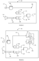
- FIG. 1 shows a voice activation system 100.
- the voice activation system 100 includes a buffer 104 for buffering a microphone signal, a first voice activity detector 108, a second voice activity detector 118, and a router 114.
- the buffer output 106 is connected to the first voice activity detector 108.
- An output 110 of the first voice activity detector 108 is connected to an input of the router 114.
- An output 116 of the second voice activity detector 118 is connected to a second input of the router 114.
- the router 114 has a router output 112 which may be considered as the voice detector output.
- the buffer 104 is connected to a microphone 102, and the input 120 of the second voice activity detector 118 may be connected to a loudspeaker 122.
- a signal is received via the microphone 102, which is buffered using the buffer 104.
- the buffer 104 may provide temporary storage of the signal received via the microphone and may be implemented for example as a FIFO memory. In other examples the buffer 104 may be omitted.
- the buffered output may be input to the first voice activity detector 108.
- a further signal is received via the loudspeaker 122 and input into the second voice activity detector 118.
- the signal, and the further signal may have characteristics which indicate that the signal contains speech, that is to say the source of the respective signal or the further signal may be somebody speaking.
- the signal and the further signal may be considered as candidate speech signals.
- the first voice activity detector 108 processes the buffered input signal and generates an output if the buffered signal has characteristics indicative of speech.
- the second voice activity detector 118 processes the signal received from the loudspeaker 122, which is effectively being used as a microphone, and generate an output if the signal received from the loudspeaker 122 has characteristics indicative of speech.
- the router 114 may generate an output signal on the router output 112 if either the first voice activity detector 108, or the second voice activity detector 118 indicates that speech has been detected. Alternatively or in addition, the router 114 may generate an output signal on the router output 112 only when both the first voice activity detector 108, and the second voice activity detector 118 generate an output signal indicating that speech has been detected.
- the router output signal may be for example a logical value, or an interrupt.
- the first voice activity detector 108, and the second voice activity detector 118 may be implemented for example in hardware using analogue or digital filtering, or alternatively in software implemented on one or more digital signal processors, which may be low power digital signal processors for example consuming less than 1 mW.
- the voice activation system 100 may have a low power mode of operation whereby only the second voice activity detector 118 may be enabled. Since the loudspeaker 122 in many mobile audio devices does not require any power if used as a microphone, by having a first power mode whereby only the second voice activity detector 118 is enabled, the power consumption may be reduced further.
- a loudspeaker 122 may be acoustically coupled to a user.
- the voice activity detector 100 is incorporated in a mobile phone, in a handset mode of operation the speaker may be pressed against the ear of a user, whereas the microphone is not in close contact with a user.
- the sounds resulting in false positive results for speech detection are typically different and so by combining the signals, the false positive detector results may be reduced or eliminated. Since false triggers due to signals being incorrectly identified as speech may result in high power modes being incorrectly enabled, by reducing false positive detector results, the power consumption of a mobile device may be reduced.
- Table 1 illustrates an example of signal sources that may be accepted or rejected as speech by the first voice activity detector 108, denoted as the Microphone Voice Activity Detector (VAD) and the second voice activity detector 118, denoted as the Speaker-as-Microphone VAD.
- the speaker will be closely coupled to the ear of a user whereas the microphone is not in close contact with a user.
- the Speaker-as Microphone VAD and Microphone VAD
- many of the common sources of background noise may be rejected since only a user talking may be accepted by both the Microphone VAD and the Speaker-as-Microphone VAD.
- the voice activation system 100 may be implemented in hardware, software, or a combination of hardware and software.
- Typical examples of voice activity detectors known to the skilled person may include extraction and classification of features such as zero crossing rate, correlation coefficients and spectral power in different frequency bands.
- FIG. 2 shows a voice activation system 200.
- the voice activation system 200 may include a buffer 204 for buffering a microphone signal, a keyword recognizer 214, a speech recognizer 208, a first voice activity detector 216, a second voice activity detector 226, and a logic AND-gate or AND-function 220.
- the AND-gate 220 may be implemented as a hardware logic circuit or a software logical AND operation.
- the buffer output 206 may be connected to the first voice activity detector 216, the keyword recognizer, and the speech recognizer 208.
- An output 218 of the first voice activity detector 216 may be connected to an input of the AND-gate 220.
- An output 224 of the second voice activity detector 226 may be connected to a second input of the AND-gate 220.
- the AND-gate 220 has an AND-gate output 222 which may be connected to a keyword recognizer 214.
- the AND-gate output 222 may be considered as the voice detector output.
- An output 212 of the keyword recognizer 214 may be connected to a speech recognizer 208.
- the microphone buffer 204 may be connected to a microphone 202, and the input 228 of the second voice activity detector 226 may be connected to a loudspeaker 230.
- a signal may be received via the microphone 202, which is buffered using the buffer 204.
- the buffered output may be input to the first voice activity detector 216.
- a further signal may be received via the loudspeaker 230 on input 228 to the second voice activity detector 226.
- the signal, and the further signal may have characteristics which indicate that the signal contain speech, that is to say the source of the respective signal or further signal may be somebody speaking.
- the signal and the further signal may be considered as candidate speech signals.
- the first voice activity detector 216 may process the buffered input signal and generate an output if the buffered signal has characteristics indicative of speech.
- the second voice activity detector 226 may process the signal received from the loudspeaker 230, which is effectively being used as a microphone, and generate an output if the signal received from the loudspeaker 230 has characteristics indicative of speech.
- these characteristics may include for example a higher auto-correlation relative to some background noise sources, a predictable zero-crossing rate, typical energy bursts in amplitude and timing corresponding to alternate speaking and silent periods.
- the AND-gate 220 may generate an output signal on the AND output 222 when both the first voice activity detector 216, and the second voice activity detector 226 generate an output signal indicating that speech has been detected.
- the voice activation system may have a first power mode whereby the first voice activity detector 216, the second voice activity detector 226, the buffer 204, and the AND gate 220 may be enabled. If both first voice activity detector 216 and the second voice activity detector 226 indicate a candidate speech signal, then the output signal generated on the AND output 222 may be used to enable the keyword recogniser 214. Once the keyword recogniser 214 is enabled, the voice activation system may be considered to be in a second power mode. In the second power mode, the keyword recogniser may process the buffered microphone signal contained in buffer 204. By buffering the microphone signal in the buffer 204, the potential speech contained within the signal may be retained for a short period of time, which may reduce the amount of potential data that is lost.
- the keyword recogniser may be typically implemented by software running on a digital signal processor.
- the keyword recogniser 214 may process the buffered signal received via the microphone 202. If the buffered signal contains one of the keywords, the keyword recogniser 214 may generate an output event on the keyword recogniser output 212. The output event generated by the keyword recogniser 214 may be used to enable the speech recogniser 208.
- the voice activation system 200 may be considered to be in a third power mode. It will be appreciated that the power consumption required increases from the first power mode to the second power mode to the third power mode.
- the speech recogniser 208 may recognise more complex words and phrases contained in the signal received via the microphone 202.
- the first voice activity detector 216, and the second voice activity detector 226 may be implemented for example in hardware using analogue or digital filtering, or alternatively in software implemented on a digital signal processor (DSP), which may be a low power digital signal processor for example consuming less than 1 mW.
- DSP digital signal processor
- the keyword recognizer 212 and the speech recognizer 208 may be implemented in hardware, software or a combination of hardware and software.
- FIG. 3 shows a voice activation system 300.
- the voice activation system 300 may include a microphone buffer 302 for buffering a microphone signal, a speaker buffer 332 for buffering a speaker-as-microphone signal, a keyword recognizer 312, a speech recognizer 308, a first voice activity detector 316, a second voice activity detector 326, a logic AND-gate or AND-function 320.
- the AND-gate 320 may be implemented as a hardware logic circuit or a software logical AND operation.
- the microphone buffer output 314 may be connected to the first voice activity detector 316 and a first input of mixer 304.
- the speaker buffer output 328 may be connected to a second input of mixer 304 and to the second voice activity detector 326.
- a mixer output 306 may be connected to the speech recognizer 308 and the keyword recognizer 312.
- An output 318 of the first voice activity detector 316 may be connected to an input of the AND-gate 320.
- An output 324 of the second voice activity detector 326 may be connected to a second input of the AND-gate 320.
- the AND-gate 320 has an AND-gate output 322 which may be connected to a keyword recognizer 312.
- An output 310 of the keyword recognizer 312 may be connected to a speech recognizer 308.
- the microphone buffer 302 may be connected to a microphone 336, and the speaker-as-microphone buffer 332 may have an input 330 connected to a loudspeaker 334.
- a signal may be received via the microphone 336 and buffered by microphone buffer 302.
- the buffered output from the microphone 336 may be input to the first voice activity detector 316.
- a further signal may be received via the speaker 334, which is buffered by the speaker-as-microphone buffer 332.
- the buffered output from the speaker 334 may be input to the second voice activity detector 316.
- the signal, and the further signal may have characteristics which indicate that the signal contain speech, that is to say the source of the respective signal or the further signal may be somebody speaking.
- the signal and the further signal may be considered as candidate speech signals.
- the first voice activity detector 316 may process the buffered input signal and generate an output if the buffered signal has characteristics indicative of speech.
- the second voice activity detector 326 may process the signal received from the loudspeaker 334, which is effectively being used as a microphone, and generate an output if the signal received from the loudspeaker 334 has characteristics indicative of speech.
- the AND-gate 320 may generate an output signal on the AND output 322 when both the first voice activity detector 316, and the second voice activity detector 326 generate an output signal indicating that speech has been detected.
- the voice activation system 300 may have a first power mode whereby the first voice activity detector 316, the second voice activity detector 326, the microphone buffer 302, the speaker-as-microphone buffer 332 and the AND gate 320 may be enabled or powered on. If both first voice activity detector 316 and the second voice activity detector 326 indicate a candidate speech signal, then the output signal generated on the AND output 322 may be used to enable the keyword recogniser 322. Once the keyword recogniser 322 is enabled, the voice activation system may be considered to be in a second power mode. In the second power mode, the keyword recogniser may process a weighted mix of the buffered microphone signal and the buffered speaker-as-microphone signal.
- the potential speech contained within the signal may be retained for a short period of time, typically 1 or 2 milliseconds, which may reduce the amount of potential speech data that is lost.
- the microphone buffer 302 and the speaker-as-microphone buffer 322 may be implemented by as temporary data store such as for example a FIFO memory structure.
- the mixing of the speaker-as-microphone signal with the microphone signal may result in an improved signal to noise ratio compared to the microphone signal, since in use, the loudspeaker may be for example closely coupled to the user.
- the keyword recogniser 312 may for example be implemented by software which may be executed on a digital signal processor or other microprocessor.
- the keyword recogniser 312 may process the signal on mixer output 306. If the output mixed signal 306 contains one of the keywords, the keyword recogniser 314 may generate an output event on the keyword recogniser output 310. The output event generated by the keyword recogniser 312 may be used to enable the speech recogniser 308.
- the voice activation system 300 may be considered to be in a third power mode. It will be appreciated that the power consumption required increases from the first power mode to the second power mode to the third power mode.
- the speech recogniser 308 may recognise more complex words and phrases contained in the mixed signal.
- the speech recogniser 308 may for example be implemented in software which may be executed on a digital signal processor or other microprocessor.
- the first voice activity detector 316, and the second voice activity detector 326 may be implemented for example in hardware using analogue or digital filtering, or alternatively in software implemented on digital signal processors, which may be low power digital signal processors for example consuming less than 1 mW.
- the keyword recognizer 312 and the speech recognizer 308 may be implemented in hardware, software or a combination of hardware and software.
- the keyword recognizer 312 may be omitted and the speech recognizer may be connected to the AND-gate output 322. In other examples the speech recognizer 308 may be omitted.
- the speech recognizer 308 may be implemented on a cloud computing server and the remainder of the voice activation system 300 may be incorporated into a mobile audio device for example a mobile phone.
- the output mixed signal 306 may be transmitted over a network by the mobile device to the cloud computing server incorporating the speech recognizer 308.
- the speech recognizer 308 may transmit the recognized speech data back to the mobile phone.
- FIG 4A shows a headset 400 including a voice activation system 414.
- the microphone 404 of the headset 400, and the speaker 402 of the headset 400 may be coupled to the voice activation system 414 via a connection 408 which may be for example a headset cable.
- the voice activation system 414 may be implemented using one or more of the embodiments herein described.
- FIG 4B which shows the headset 400 in use.
- the loudspeaker 402 is typically closely coupled with the ear of a user 416.
- the loudspeaker 402 may be driven by an audio amplifier (not shown).
- the loudspeaker 402 may capture the speech of the user 416 via a bone conduction path 408 denoted as Sls.
- the loudspeaker 402 may capture background noise from noise source 418 indicated by air path 410 and denoted Nls.
- the microphone 404 may capture the speech of the user 416 via the air path 406 denoted as Sm.
- the microphone 404 may capture background noise from noise source 418 indicated by air path 412 and denoted Nm. Because the headset may at least partially occlude the ear canal, a pressure chamber may be generated with which results in a low frequency boost of the bone conducted speech.
- this amplification effect known as the occlusion effect is conventionally considered undesirable in for example a hearing aids or other mobile devices, since the close coupling can cause a user to hear their own speech in a distracting way which may for example impair the intelligibility of speech from another person.
- the inventor of the present application has realised that this low frequency boost typically emphasises the voiced user speech components, which may improve the signal-to-noise ratio in the presence of background noise from noise source 418.
- the noise source 418 may include sources such as interfering speech, environmental noise such as wind noise or other noise sources.
- the energy of such noise sources is typically concentrated at the low frequencies, which may include for example frequencies below 1 kHz.
- a voice activation system as herein described may be incorporated into mobile audio devices such as, for example mobile phones, hearing aids, wearable devices, laptops, tablet computers, and so-called hearable devices.
- the voice activation system herein described when incorporated into mobile audio devices may improve the reliability of the voice activity detection without any increase in components since, typically the speaker and microphone may already be required for other functionality.
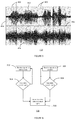
- Figure 5 shows a graph of speech in a noisy environment 450 for the headset 400 detected simultaneously via the headset speaker 402 and the microphone 404.
- the headset 400 is positioned with the speaker 402 closely coupled to the ear of a user 416.
- the x-axis 456 denotes time and the y-axis 458 denotes amplitude.
- the graph line 452 shows speech detected via the headset speaker 402 when configured as a microphone.
- the graph line 454 shows the same user speech detected via the microphone 404 of figure 4B which may be located on the headset cable 408.
- the region between the dashed lines 460 illustrates a portion of the signal containing noise only.
- the region between the dashed lines 462 illustrates a portion of the signal containing speech and noise. As can be seen the level of noise in region 460 detected via the speaker 402 configured as a microphone is lower than the level of noise in region 460 detected via the microphone 404.
- Figure 6 shows a method of voice activation 500.
- a signal is received via a microphone.
- the method then moves to step 504 where a check is made to determine whether or not a candidate speech signal has been detected. If a candidate speech signal has not been detected, the method returns to step 502. If a candidate speech signal has been detected, then a voice activity output signal is generated in step 510.
- a signal is received via a speaker configured as a microphone.
- the signal received is checked to determine whether or not it is a candidate speech signal. If no speech is detected then the method returns to step 506. If speech has been detected, the method moves to step 510 and the voice activity output signal may be generated.
- a voice activation system including a first voice activity detector for receiving a first signal from a microphone; a second voice activity detector for receiving a second signal from a speaker; a voice detector output coupled to the output of the first voice activity detector and the second voice activity detector.
- the first detector and the second detector are operable to generate an output signal in response to a candidate speech signal received on the respective detector inputs and the voice activation system is configured to generate a voice detector output signal when at least one of the first detector output and the second detector output indicate that speech has been detected.
- the voice activation system may reduce the average power consumption and increase the recognition rate of an always-on voice activation solution for headsets or other mobile audio devices.
Landscapes
- Engineering & Computer Science (AREA)
- Physics & Mathematics (AREA)
- Health & Medical Sciences (AREA)
- Acoustics & Sound (AREA)
- Computational Linguistics (AREA)
- Audiology, Speech & Language Pathology (AREA)
- Human Computer Interaction (AREA)
- Multimedia (AREA)
- Signal Processing (AREA)
- General Engineering & Computer Science (AREA)
- Theoretical Computer Science (AREA)
- General Health & Medical Sciences (AREA)
- Otolaryngology (AREA)
- Computer Hardware Design (AREA)
- Computing Systems (AREA)
- General Physics & Mathematics (AREA)
- Telephone Function (AREA)
Abstract
Description
- This disclosure relates to a voice activation system for a mobile audio device.
- Mobile audio devices such as mobile phones are getting smarter and are more and more equipped with "always-on" functionalities, which continuously sense the environment to perform anticipative actions such as device wake-up, voice keyword detection. Always-on functionalities have very low power requirements, which may be typically lower than 1 milliwatt (mW), and usually make use of dedicated sensors and low power hardware components implemented as integrated circuits in order to function independently from the main processor. This is particularly the case for wearable mobile audio devices such as active earbuds or watches. In case of voice activation, the main processor is only woken up by the voice activation system if a dedicated keyword has been recognized. In order to minimize power consumption, a multi-stage detection is usually applied.
- Various aspects are defined in the accompanying claims. In a first aspect there is defined a voice activation system for a mobile audio device comprising a speaker and a microphone, the voice activation system comprising: a first voice activity detector having a first detector input for receiving a first signal from a microphone and a first detector output; a second voice activity detector having a second detector input for receiving a second signal from a speaker and a second detector output; a voice detector output coupled to the first detector output and the second detector output; wherein the first detector and the second detector are operable to generate an output signal in response to a candidate speech signal received on the respective detector inputs and wherein the voice activation system is configured to generate a voice detector output signal when at least one of the first detector output and the second detector output indicate that speech has been detected.
- In embodiments the voice activity detector may be configured to generate a voice detector output signal when both the first detector output and the second detector output indicate that speech has been detected.
- In embodiments, the voice activation system may have a first power mode and a second power mode, wherein in the first power mode only the second voice activity detector is enabled , in the second power mode both the first voice activity detector and the second voice activity detector are enabled, and wherein in operation the voice activation system is configured to change from the first power mode to the second power mode in response to the second detector indicating that speech has been detected.
- In embodiments, the voice activation system may comprise a keyword recognizer having a first keyword recognizer input configured to receive at least one of a first signal, a second signal, and a weighted combination of the first signal and the second signal, and a second keyword recognizer input coupled to the voice detector output, wherein the keyword recognizer is enabled in response to a signal on the voice detector output indicating that speech has been detected, and wherein the keyword recognizer is operable to generate an output in response to a speech signal comprising a keyword received on the first keyword recognizer input.
- The keyword recognizer may receive a first signal from a microphone, a second signal from a speaker-as-microphone or a weighted combination of the first signal and the second signal. The received signal may be provided by a mixer.
- In embodiments, the voice activation system may comprise a speech recognizer having a first speech recognizer input configured to receive at least one of a first signal, a second signal, and a weighted combination of the first signal and the second signal, and a second speech recognizer input coupled to the keyword recognizer output, wherein the speech recognizer is enabled in response to the keyword recognizer indicating that a keyword has been detected.
- The speech recognizer may be enabled in response to a keyword being detected. The speech recognizer may receive a first signal from a microphone, a second signal from a speaker-as-microphone or a weighted combination of the microphone signal. The received signal may be provided by a mixer.
- In embodiments the voice activation system may comprise a speech recognizer having a first speech recognizer input configured to receive at least one of a first signal, a second signal, and a weighted combination of the first signal and the second signal, and a second speech recognizer input coupled to the voice detector output, and wherein the speech recognizer is enabled in response to speech being detected.
- In embodiments, the voice activation system may comprise a microphone buffer coupled to the first detector input, wherein the first voice activity detector is configured to receive a buffered signal from the microphone.
- In embodiments, the voice activation system may comprise a speaker-as-microphone buffer coupled to the second detector input, wherein the second detector is configured to receive a buffered signal from the speaker configured as a microphone.
- Embodiments of the voice activation system may be included in a headset comprising a microphone coupled to the first voice activity detector input and a speaker coupled to the second voice activity detector input.
- Embodiments of the voice activation system may be included in a hearing aid comprising a microphone coupled to the first voice activity detector input and a speaker coupled to the second voice activity detector input.
- Embodiments of the voice activation system may be included in a mobile audio device comprising a microphone coupled to the first voice activity detector input and a speaker coupled to the second voice activity detector input.
- In a second aspect there is defined a method of voice activation for an audio device comprising a speaker and a microphone, the method comprising: generating a first detector output signal in response to a first signal comprising a candidate speech signal from a microphone; generating a second detector output signal in response to a second signal comprising the candidate speech signal from a speaker configured as a microphone; generating a voice activity output signal in response to at least one of the first detector output signal and the second detector output signal.
- In embodiments, the method may further comprise generating a voice activity output signal in response to both the first detector output signal and the second detector output signal.
- In embodiments of the method, the second detector output signal may be generated in response to the first detector output signal and the second signal comprising the candidate speech signal from a speaker configured as a microphone.
- In embodiments, the method may comprise activating a keyword detector in response to the voice activity detector output signal.
- In embodiments, the method may comprise detecting a keyword and activating a speech recognizer in response to detecting a keyword.
- In embodiments, the method may further comprise buffering at least one of the first signal and the second signal.
- In the figures and description like reference numerals refer to like features. Embodiments are now described in detail, by way of example only, illustrated by the accompanying drawings in which:
-
Figure 1 shows a voice activation system according to an embodiment. -
Figure 2 illustrates a voice activation system according to an embodiment. -
Figure 3 shows a voice activation system according to an embodiment. -
Figure 4A illustrates a headset including a voice activation system according to an embodiment. -
Figure 4B shows the headset offigure 4A in use. -
Figure 5 shows a graph of a signal detected via a speaker and the microphone of the headset offigure 4B . -
Figure 6 shows a method of voice activity detection according to an embodiment. -
Figure 1 shows avoice activation system 100. Thevoice activation system 100 includes abuffer 104 for buffering a microphone signal, a firstvoice activity detector 108, a secondvoice activity detector 118, and arouter 114. Thebuffer output 106 is connected to the firstvoice activity detector 108. Anoutput 110 of the firstvoice activity detector 108 is connected to an input of therouter 114. Anoutput 116 of the secondvoice activity detector 118 is connected to a second input of therouter 114. Therouter 114 has arouter output 112 which may be considered as the voice detector output. - In operation of the
voice activation system 100, thebuffer 104 is connected to amicrophone 102, and theinput 120 of the secondvoice activity detector 118 may be connected to aloudspeaker 122. A signal is received via themicrophone 102, which is buffered using thebuffer 104. Thebuffer 104 may provide temporary storage of the signal received via the microphone and may be implemented for example as a FIFO memory. In other examples thebuffer 104 may be omitted. - The buffered output may be input to the first
voice activity detector 108. A further signal is received via theloudspeaker 122 and input into the secondvoice activity detector 118. The signal, and the further signal may have characteristics which indicate that the signal contains speech, that is to say the source of the respective signal or the further signal may be somebody speaking. The signal and the further signal may be considered as candidate speech signals. The firstvoice activity detector 108 processes the buffered input signal and generates an output if the buffered signal has characteristics indicative of speech. The secondvoice activity detector 118 processes the signal received from theloudspeaker 122, which is effectively being used as a microphone, and generate an output if the signal received from theloudspeaker 122 has characteristics indicative of speech. Therouter 114 may generate an output signal on therouter output 112 if either the firstvoice activity detector 108, or the secondvoice activity detector 118 indicates that speech has been detected. Alternatively or in addition, therouter 114 may generate an output signal on therouter output 112 only when both the firstvoice activity detector 108, and the secondvoice activity detector 118 generate an output signal indicating that speech has been detected. The router output signal may be for example a logical value, or an interrupt. - The first
voice activity detector 108, and the secondvoice activity detector 118 may be implemented for example in hardware using analogue or digital filtering, or alternatively in software implemented on one or more digital signal processors, which may be low power digital signal processors for example consuming less than 1 mW. Thevoice activation system 100 may have a low power mode of operation whereby only the secondvoice activity detector 118 may be enabled. Since theloudspeaker 122 in many mobile audio devices does not require any power if used as a microphone, by having a first power mode whereby only the secondvoice activity detector 118 is enabled, the power consumption may be reduced further. - Alternatively or in addition, by only outputting a detection signal on the
router output 112, when both the firstvoice activity detector 108, and the secondvoice activity detector 118 indicate that speech has been detected, the reliability of the speech detection may be significantly improved. This is because the inventors of the present application have realised that in many applications, aloudspeaker 122 may be acoustically coupled to a user. For example if thevoice activity detector 100 is incorporated in a mobile phone, in a handset mode of operation the speaker may be pressed against the ear of a user, whereas the microphone is not in close contact with a user. In this case the sounds resulting in false positive results for speech detection are typically different and so by combining the signals, the false positive detector results may be reduced or eliminated. Since false triggers due to signals being incorrectly identified as speech may result in high power modes being incorrectly enabled, by reducing false positive detector results, the power consumption of a mobile device may be reduced. - Table 1 illustrates an example of signal sources that may be accepted or rejected as speech by the first
voice activity detector 108, denoted as the Microphone Voice Activity Detector (VAD) and the secondvoice activity detector 118, denoted as the Speaker-as-Microphone VAD. Typically in this example, the speaker will be closely coupled to the ear of a user whereas the microphone is not in close contact with a user. By using a combination of the Speaker-as Microphone VAD and Microphone VAD many of the common sources of background noise may be rejected since only a user talking may be accepted by both the Microphone VAD and the Speaker-as-Microphone VAD.Table 1 Speaker-as-Microphone VAD Microphone VAD User talking Accept Accept Interfering Talkers Reject Accept Radio / TV Reject Accept Interfering Double-Talk Reject Accept User body noise (e.g. swallowing) Accept Reject Handling noise Accept Reject Stationary noise. Reject Reject - The
voice activation system 100 may be implemented in hardware, software, or a combination of hardware and software. Typical examples of voice activity detectors known to the skilled person may include extraction and classification of features such as zero crossing rate, correlation coefficients and spectral power in different frequency bands. -
Figure 2 shows avoice activation system 200. Thevoice activation system 200 may include abuffer 204 for buffering a microphone signal, akeyword recognizer 214, aspeech recognizer 208, a firstvoice activity detector 216, a secondvoice activity detector 226, and a logic AND-gate or AND-function 220. It will be appreciated that the AND-gate 220 may be implemented as a hardware logic circuit or a software logical AND operation. Thebuffer output 206 may be connected to the firstvoice activity detector 216, the keyword recognizer, and thespeech recognizer 208. Anoutput 218 of the firstvoice activity detector 216 may be connected to an input of theAND-gate 220. Anoutput 224 of the secondvoice activity detector 226 may be connected to a second input of theAND-gate 220. TheAND-gate 220 has anAND-gate output 222 which may be connected to akeyword recognizer 214. TheAND-gate output 222 may be considered as the voice detector output. Anoutput 212 of thekeyword recognizer 214 may be connected to aspeech recognizer 208. - In operation of the
voice activation system 200, themicrophone buffer 204 may be connected to amicrophone 202, and theinput 228 of the secondvoice activity detector 226 may be connected to aloudspeaker 230. A signal may be received via themicrophone 202, which is buffered using thebuffer 204. The buffered output may be input to the firstvoice activity detector 216. A further signal may be received via theloudspeaker 230 oninput 228 to the secondvoice activity detector 226. The signal, and the further signal may have characteristics which indicate that the signal contain speech, that is to say the source of the respective signal or further signal may be somebody speaking. The signal and the further signal may be considered as candidate speech signals. The firstvoice activity detector 216 may process the buffered input signal and generate an output if the buffered signal has characteristics indicative of speech. The secondvoice activity detector 226 may process the signal received from theloudspeaker 230, which is effectively being used as a microphone, and generate an output if the signal received from theloudspeaker 230 has characteristics indicative of speech. The skilled person will appreciate that these characteristics may include for example a higher auto-correlation relative to some background noise sources, a predictable zero-crossing rate, typical energy bursts in amplitude and timing corresponding to alternate speaking and silent periods. The AND-gate 220 may generate an output signal on the ANDoutput 222 when both the firstvoice activity detector 216, and the secondvoice activity detector 226 generate an output signal indicating that speech has been detected. - The voice activation system may have a first power mode whereby the first
voice activity detector 216, the secondvoice activity detector 226, thebuffer 204, and the ANDgate 220 may be enabled. If both firstvoice activity detector 216 and the secondvoice activity detector 226 indicate a candidate speech signal, then the output signal generated on the ANDoutput 222 may be used to enable thekeyword recogniser 214. Once thekeyword recogniser 214 is enabled, the voice activation system may be considered to be in a second power mode. In the second power mode, the keyword recogniser may process the buffered microphone signal contained inbuffer 204. By buffering the microphone signal in thebuffer 204, the potential speech contained within the signal may be retained for a short period of time, which may reduce the amount of potential data that is lost. The keyword recogniser may be typically implemented by software running on a digital signal processor. Thekeyword recogniser 214 may process the buffered signal received via themicrophone 202. If the buffered signal contains one of the keywords, thekeyword recogniser 214 may generate an output event on thekeyword recogniser output 212. The output event generated by thekeyword recogniser 214 may be used to enable thespeech recogniser 208. Once the speech recogniser is enabled, thevoice activation system 200 may be considered to be in a third power mode. It will be appreciated that the power consumption required increases from the first power mode to the second power mode to the third power mode. Thespeech recogniser 208 may recognise more complex words and phrases contained in the signal received via themicrophone 202. - The first
voice activity detector 216, and the secondvoice activity detector 226 may be implemented for example in hardware using analogue or digital filtering, or alternatively in software implemented on a digital signal processor (DSP), which may be a low power digital signal processor for example consuming less than 1 mW. Thekeyword recognizer 212 and thespeech recognizer 208 may be implemented in hardware, software or a combination of hardware and software. -
Figure 3 shows avoice activation system 300. Thevoice activation system 300 may include amicrophone buffer 302 for buffering a microphone signal, aspeaker buffer 332 for buffering a speaker-as-microphone signal, akeyword recognizer 312, aspeech recognizer 308, a firstvoice activity detector 316, a secondvoice activity detector 326, a logic AND-gate or AND-function 320. It will be appreciated that the AND-gate 320 may be implemented as a hardware logic circuit or a software logical AND operation. Themicrophone buffer output 314 may be connected to the firstvoice activity detector 316 and a first input ofmixer 304. Thespeaker buffer output 328 may be connected to a second input ofmixer 304 and to the secondvoice activity detector 326. Amixer output 306 may be connected to thespeech recognizer 308 and thekeyword recognizer 312. Anoutput 318 of the firstvoice activity detector 316 may be connected to an input of theAND-gate 320. Anoutput 324 of the secondvoice activity detector 326 may be connected to a second input of theAND-gate 320. TheAND-gate 320 has anAND-gate output 322 which may be connected to akeyword recognizer 312. Anoutput 310 of thekeyword recognizer 312 may be connected to aspeech recognizer 308. - In operation of the
voice activation system 300, themicrophone buffer 302 may be connected to amicrophone 336, and the speaker-as-microphone buffer 332 may have aninput 330 connected to aloudspeaker 334. A signal may be received via themicrophone 336 and buffered bymicrophone buffer 302. The buffered output from themicrophone 336 may be input to the firstvoice activity detector 316. A further signal may be received via thespeaker 334, which is buffered by the speaker-as-microphone buffer 332. The buffered output from thespeaker 334 may be input to the secondvoice activity detector 316. The signal, and the further signal may have characteristics which indicate that the signal contain speech, that is to say the source of the respective signal or the further signal may be somebody speaking. The signal and the further signal may be considered as candidate speech signals. The firstvoice activity detector 316 may process the buffered input signal and generate an output if the buffered signal has characteristics indicative of speech. The secondvoice activity detector 326 may process the signal received from theloudspeaker 334, which is effectively being used as a microphone, and generate an output if the signal received from theloudspeaker 334 has characteristics indicative of speech. The AND-gate 320 may generate an output signal on the ANDoutput 322 when both the firstvoice activity detector 316, and the secondvoice activity detector 326 generate an output signal indicating that speech has been detected. - The
voice activation system 300 may have a first power mode whereby the firstvoice activity detector 316, the secondvoice activity detector 326, themicrophone buffer 302, the speaker-as-microphone buffer 332 and the ANDgate 320 may be enabled or powered on. If both firstvoice activity detector 316 and the secondvoice activity detector 326 indicate a candidate speech signal, then the output signal generated on the ANDoutput 322 may be used to enable thekeyword recogniser 322. Once thekeyword recogniser 322 is enabled, the voice activation system may be considered to be in a second power mode. In the second power mode, the keyword recogniser may process a weighted mix of the buffered microphone signal and the buffered speaker-as-microphone signal. By buffering the signal and further signal in themicrophone buffer 302 and the speaker-as-microphone buffer 322, the potential speech contained within the signal may be retained for a short period of time, typically 1 or 2 milliseconds, which may reduce the amount of potential speech data that is lost. Themicrophone buffer 302 and the speaker-as-microphone buffer 322 may be implemented by as temporary data store such as for example a FIFO memory structure. The mixing of the speaker-as-microphone signal with the microphone signal may result in an improved signal to noise ratio compared to the microphone signal, since in use, the loudspeaker may be for example closely coupled to the user. - The skilled person will appreciate that the
keyword recogniser 312 may for example be implemented by software which may be executed on a digital signal processor or other microprocessor. Thekeyword recogniser 312 may process the signal onmixer output 306. If the outputmixed signal 306 contains one of the keywords, thekeyword recogniser 314 may generate an output event on thekeyword recogniser output 310. The output event generated by thekeyword recogniser 312 may be used to enable thespeech recogniser 308. Once the speech recogniser is enabled, thevoice activation system 300 may be considered to be in a third power mode. It will be appreciated that the power consumption required increases from the first power mode to the second power mode to the third power mode. Thespeech recogniser 308 may recognise more complex words and phrases contained in the mixed signal. The skilled person will appreciate that thespeech recogniser 308 may for example be implemented in software which may be executed on a digital signal processor or other microprocessor. - The first
voice activity detector 316, and the secondvoice activity detector 326 may be implemented for example in hardware using analogue or digital filtering, or alternatively in software implemented on digital signal processors, which may be low power digital signal processors for example consuming less than 1 mW. Thekeyword recognizer 312 and thespeech recognizer 308 may be implemented in hardware, software or a combination of hardware and software. - In some examples of the
voice activation system 300, thekeyword recognizer 312 may be omitted and the speech recognizer may be connected to theAND-gate output 322. In other examples thespeech recognizer 308 may be omitted. - In some examples of the
voice activation system 300, thespeech recognizer 308 may be implemented on a cloud computing server and the remainder of thevoice activation system 300 may be incorporated into a mobile audio device for example a mobile phone. In this case, once a keyword has been detected by the keyword detector, the outputmixed signal 306 may be transmitted over a network by the mobile device to the cloud computing server incorporating thespeech recognizer 308. Thespeech recognizer 308 may transmit the recognized speech data back to the mobile phone. -
Figure 4A shows aheadset 400 including avoice activation system 414. Themicrophone 404 of theheadset 400, and thespeaker 402 of theheadset 400 may be coupled to thevoice activation system 414 via aconnection 408 which may be for example a headset cable. Thevoice activation system 414 may be implemented using one or more of the embodiments herein described. Now with reference tofigure 4B which shows theheadset 400 in use. In operation, theloudspeaker 402 is typically closely coupled with the ear of auser 416. In normal operation of theloudspeaker 402, that is to say when the loudspeaker is being used to output audio, theloudspeaker 402 may be driven by an audio amplifier (not shown). When used as a microphone, theloudspeaker 402 may capture the speech of theuser 416 via abone conduction path 408 denoted as Sls. Theloudspeaker 402 may capture background noise fromnoise source 418 indicated byair path 410 and denoted Nls. Themicrophone 404 may capture the speech of theuser 416 via theair path 406 denoted as Sm. Themicrophone 404 may capture background noise fromnoise source 418 indicated byair path 412 and denoted Nm. Because the headset may at least partially occlude the ear canal, a pressure chamber may be generated with which results in a low frequency boost of the bone conducted speech. As will be appreciated, this amplification effect known as the occlusion effect is conventionally considered undesirable in for example a hearing aids or other mobile devices, since the close coupling can cause a user to hear their own speech in a distracting way which may for example impair the intelligibility of speech from another person. The inventor of the present application has realised that this low frequency boost typically emphasises the voiced user speech components, which may improve the signal-to-noise ratio in the presence of background noise fromnoise source 418. Thenoise source 418 may include sources such as interfering speech, environmental noise such as wind noise or other noise sources. The energy of such noise sources is typically concentrated at the low frequencies, which may include for example frequencies below 1 kHz. - In other examples, a voice activation system as herein described may be incorporated into mobile audio devices such as, for example mobile phones, hearing aids, wearable devices, laptops, tablet computers, and so-called hearable devices. The voice activation system herein described when incorporated into mobile audio devices, may improve the reliability of the voice activity detection without any increase in components since, typically the speaker and microphone may already be required for other functionality.
-
Figure 5 shows a graph of speech in anoisy environment 450 for theheadset 400 detected simultaneously via theheadset speaker 402 and themicrophone 404. Theheadset 400 is positioned with thespeaker 402 closely coupled to the ear of auser 416. Thex-axis 456 denotes time and the y-axis 458 denotes amplitude. Thegraph line 452 shows speech detected via theheadset speaker 402 when configured as a microphone. Thegraph line 454 shows the same user speech detected via themicrophone 404 offigure 4B which may be located on theheadset cable 408. The region between the dashedlines 460 illustrates a portion of the signal containing noise only. The region between the dashedlines 462 illustrates a portion of the signal containing speech and noise. As can be seen the level of noise inregion 460 detected via thespeaker 402 configured as a microphone is lower than the level of noise inregion 460 detected via themicrophone 404. -
Figure 6 shows a method ofvoice activation 500. In step 502 a signal is received via a microphone. The method then moves to step 504 where a check is made to determine whether or not a candidate speech signal has been detected. If a candidate speech signal has not been detected, the method returns to step 502. If a candidate speech signal has been detected, then a voice activity output signal is generated instep 510. In parallel to step 502, in step 506 a signal is received via a speaker configured as a microphone. Instep 508 the signal received is checked to determine whether or not it is a candidate speech signal. If no speech is detected then the method returns to step 506. If speech has been detected, the method moves to step 510 and the voice activity output signal may be generated. - Herein is described a voice activation system including a first voice activity detector for receiving a first signal from a microphone; a second voice activity detector for receiving a second signal from a speaker; a voice detector output coupled to the output of the first voice activity detector and the second voice activity detector. The first detector and the second detector are operable to generate an output signal in response to a candidate speech signal received on the respective detector inputs and the voice activation system is configured to generate a voice detector output signal when at least one of the first detector output and the second detector output indicate that speech has been detected. The voice activation system may reduce the average power consumption and increase the recognition rate of an always-on voice activation solution for headsets or other mobile audio devices.
- Although the appended claims are directed to particular combinations of features, it should be understood that the scope of the disclosure of the present invention also includes any novel feature or any novel combination of features disclosed herein either explicitly or implicitly or any generalisation thereof, whether or not it relates to the same invention as presently claimed in any claim and whether or not it mitigates any or all of the same technical problems as does the present invention.
- Features which are described in the context of separate embodiments may also be provided in combination in a single embodiment. Conversely, various features which are, for brevity, described in the context of a single embodiment, may also be provided separately or in any suitable sub combination.
- The applicant hereby gives notice that new claims may be formulated to such features and/or combinations of such features during the prosecution of the present application or of any further application derived therefrom.
- For the sake of completeness it is also stated that the term "comprising" does not exclude other elements or steps, the term "a" or "an" does not exclude a plurality, a single processor or other unit may fulfil the functions of several means recited in the claims and reference signs in the claims shall not be construed as limiting the scope of the claims.
Claims (15)
- A voice activation system for a mobile audio device comprising a speaker and a microphone, the voice activation system comprising:a first voice activity detector having a first detector input for receiving a first signal from a microphone and a first detector output;a second voice activity detector having a second detector input for receiving a second signal from a speaker and a second detector output;a voice detector output coupled to the first detector output and the second detector output;wherein the first voice activity detector and the second voice activity detector are operable to generate an output signal in response to a candidate speech signal received on the respective detector inputs and wherein the voice activation system is configured to generate a voice detector output signal when at least one of the first detector output and the second detector output indicate that speech has been detected.
- The voice activation system of claim 1 wherein the voice activity detector is configured to generate a voice detector output signal when both the first detector output and the second detector output indicate that speech has been detected.
- The voice activation system of any preceding claim having a first power mode and a second power mode, wherein in the first power mode, only the second voice activity detector is enabled and wherein in the second power mode, both the first voice activity detector and the second voice activity detector are enabled and wherein in operation the voice activation system is configured to change from the first power mode to the second power mode in response to the second detector indicating that speech has been detected.
- The voice activation system of any preceding claim further comprising a keyword recognizer having a first keyword recognizer input configured to receive at least one of the first signal ,the second signal, and a weighted mix of the first signal and the second signal, and a second keyword recognizer input coupled to the voice detector output, wherein the keyword recognizer is enabled in response to speech being detected, and wherein the keyword recognizer is operable to generate an output in response to a speech signal comprising a keyword received on the first keyword recognizer input.
- The voice activation system of any preceding claim further comprising a speech recognizer having a first speech recognizer input configured to receive at least one of the first signal, the second signal, and a weighted mix of the first signal and the second signal, and a second speech recognizer input coupled to the keyword recognizer output, wherein the speech recognizer is enabled in response to the keyword recognizer indicating that a keyword has been detected.
- The voice activation system of any of claims 1 to 3 further comprising a speech recognizer having a first speech recognizer input configured to receive at least one of the first signal, the second signal, and a weighted mix of the first signal and the second signal, and a second speech recognizer input coupled to the voice detector output, wherein the speech recognizer is enabled in response to speech being detected.
- The voice activation system of any preceding claim further comprising a microphone buffer coupled to the first detector input, wherein the first voice activity detector is configured to receive a buffered signal from the microphone.
- The voice activation system of any preceding claim further comprising a speaker-as-microphone buffer coupled to the second detector input, wherein the second detector is configured to receive a buffered signal from the speaker when configured as a microphone.
- A headset comprising the voice activation system of any preceding claim, the headset comprising a microphone coupled to the first voice activity detector input and a speaker coupled to the second voice activity detector input.
- A hearing aid comprising the voice activation system of any of claims 1 to 8, the hearing aid comprising a microphone coupled to the first voice activity detector input and a speaker coupled to the second voice activity detector input.
- A mobile audio device comprising the voice activation system of any of claims 1 to 8, the hearing aid comprising a microphone coupled to the first voice activity detector input and a speaker coupled to the second voice activity detector input.
- A method of voice activation for an audio device comprising a speaker and a microphone, the method comprising:generating a first detector output signal in response to a first signal comprising a candidate speech signal from a microphone;generating a second detector output signal in response to a second signal comprising the candidate speech signal from a speaker configured as a microphone;generating a voice activity output signal in response to at least one of the first detector output signal and the second detector output signal.
- The method of claim 12 further comprising generating a voice activity output signal in response to both the first detector output signal and the second detector output signal.
- The method of claim 12 or 13 further comprising changing from a first power mode to the second power mode in response to the first detector output signal, wherein the first power mode has a lower power consumption than the second power mode.
- The method of any of claims 12 to 14 further comprising activating a keyword detector in response to the voice activity detector output signal.
Priority Applications (3)
| Application Number | Priority Date | Filing Date | Title |
|---|---|---|---|
| EP15201872.7A EP3185244B1 (en) | 2015-12-22 | 2015-12-22 | Voice activation system |
| CN201611126055.2A CN106992015B (en) | 2015-12-22 | 2016-12-08 | Voice activation system |
| US15/384,461 US10043515B2 (en) | 2015-12-22 | 2016-12-20 | Voice activation system |
Applications Claiming Priority (1)
| Application Number | Priority Date | Filing Date | Title |
|---|---|---|---|
| EP15201872.7A EP3185244B1 (en) | 2015-12-22 | 2015-12-22 | Voice activation system |
Publications (2)
| Publication Number | Publication Date |
|---|---|
| EP3185244A1 true EP3185244A1 (en) | 2017-06-28 |
| EP3185244B1 EP3185244B1 (en) | 2019-02-20 |
Family
ID=55027414
Family Applications (1)
| Application Number | Title | Priority Date | Filing Date |
|---|---|---|---|
| EP15201872.7A Active EP3185244B1 (en) | 2015-12-22 | 2015-12-22 | Voice activation system |
Country Status (3)
| Country | Link |
|---|---|
| US (1) | US10043515B2 (en) |
| EP (1) | EP3185244B1 (en) |
| CN (1) | CN106992015B (en) |
Cited By (3)
| Publication number | Priority date | Publication date | Assignee | Title |
|---|---|---|---|---|
| DE102018215411B3 (en) | 2018-09-11 | 2019-12-12 | Audi Ag | Method for simultaneously operating a loudspeaker arrangement in a loudspeaker function and in a microphone function as well as loudspeaker arrangement |
| EP3890342A4 (en) * | 2019-01-04 | 2022-01-19 | Matrixed Reality Technology Co., Ltd. | METHOD AND APPARATUS FOR AWAKENING A PORTABLE DEVICE |
| GB2605121A (en) * | 2021-02-08 | 2022-09-28 | Prevayl Innovations Ltd | An electronics module for a wearable articel, a systemm, and a method of activation of an electronics module for a wearable article |
Families Citing this family (21)
| Publication number | Priority date | Publication date | Assignee | Title |
|---|---|---|---|---|
| JP6569926B2 (en) * | 2016-08-17 | 2019-09-04 | パナソニックIpマネジメント株式会社 | Speech input device, translation device, speech input method, and speech input program |
| US10593328B1 (en) * | 2016-12-27 | 2020-03-17 | Amazon Technologies, Inc. | Voice control of remote device |
| US10121494B1 (en) * | 2017-03-30 | 2018-11-06 | Amazon Technologies, Inc. | User presence detection |
| US11290802B1 (en) * | 2018-01-30 | 2022-03-29 | Amazon Technologies, Inc. | Voice detection using hearable devices |
| WO2019169272A1 (en) | 2018-03-02 | 2019-09-06 | Continental Automotive Systems, Inc. | Enhanced barge-in detector |
| US10847178B2 (en) * | 2018-05-18 | 2020-11-24 | Sonos, Inc. | Linear filtering for noise-suppressed speech detection |
| DE102018209824A1 (en) * | 2018-06-18 | 2019-12-19 | Sivantos Pte. Ltd. | Method for controlling the data transmission between at least one hearing aid and a peripheral device of a hearing aid system and hearing aid |
| JP7001029B2 (en) * | 2018-09-11 | 2022-01-19 | 日本電信電話株式会社 | Keyword detector, keyword detection method, and program |
| CN114882871A (en) * | 2018-10-29 | 2022-08-09 | 恒玄科技(上海)股份有限公司 | Earphone device, voice processing system and voice processing method |
| CN110265007B (en) * | 2019-05-11 | 2020-07-24 | 出门问问信息科技有限公司 | Control method and control device of voice assistant system and Bluetooth headset |
| US11215500B2 (en) * | 2019-06-01 | 2022-01-04 | Apple Inc. | Environmental and aggregate acoustic dosimetry |
| US11499865B2 (en) * | 2019-06-01 | 2022-11-15 | Apple Inc. | Environmental acoustic dosimetry with water event detection |
| CN114762361A (en) | 2019-12-17 | 2022-07-15 | 思睿逻辑国际半导体有限公司 | Bidirectional microphone system using a loudspeaker as one of the microphones |
| CN111429911A (en) * | 2020-03-11 | 2020-07-17 | 云知声智能科技股份有限公司 | Method and device for reducing power consumption of speech recognition engine in noise scene |
| CN113393865B (en) * | 2020-03-13 | 2022-06-03 | 阿里巴巴集团控股有限公司 | Power consumption control, mode configuration and VAD method, apparatus and storage medium |
| US11778361B1 (en) * | 2020-06-24 | 2023-10-03 | Meta Platforms Technologies, Llc | Headset activation validation based on audio data |
| US12342137B2 (en) * | 2021-05-10 | 2025-06-24 | Nureva Inc. | System and method utilizing discrete microphones and virtual microphones to simultaneously provide in-room amplification and remote communication during a collaboration session |
| US12356146B2 (en) | 2022-03-03 | 2025-07-08 | Nureva, Inc. | System for dynamically determining the location of and calibration of spatially placed transducers for the purpose of forming a single physical microphone array |
| US12549917B2 (en) | 2022-03-22 | 2026-02-10 | Nureva, Inc. | System for dynamically forming a virtual microphone coverage map from a combined array to any dimension, size and shape based on individual microphone element locations |
| US12457465B2 (en) | 2022-03-28 | 2025-10-28 | Nureva, Inc. | System for dynamically deriving and using positional based gain output parameters across one or more microphone element locations |
| US12587787B2 (en) | 2023-05-09 | 2026-03-24 | Nureva, Inc. | System for dynamically adjusting the gain structure of sound sources contained within one or more inclusion and exclusion zones |
Citations (6)
| Publication number | Priority date | Publication date | Assignee | Title |
|---|---|---|---|---|
| EP1503368A1 (en) * | 2003-07-29 | 2005-02-02 | Microsoft Corporation | Head mounted multi-sensory audio input system |
| US20050136848A1 (en) * | 2003-12-22 | 2005-06-23 | Matt Murray | Multi-mode audio processors and methods of operating the same |
| US20090271190A1 (en) * | 2008-04-25 | 2009-10-29 | Nokia Corporation | Method and Apparatus for Voice Activity Determination |
| US20140270312A1 (en) * | 2013-03-14 | 2014-09-18 | Cirrus Logic, Inc. | Systems and methods for using a speaker as a microphone in a mobile device |
| US20150120299A1 (en) * | 2013-10-29 | 2015-04-30 | Knowles Electronics, Llc | VAD Detection Apparatus and Method of Operating the Same |
| US20150139428A1 (en) * | 2013-11-20 | 2015-05-21 | Knowles IPC (M) Snd. Bhd. | Apparatus with a speaker used as second microphone |
Family Cites Families (16)
| Publication number | Priority date | Publication date | Assignee | Title |
|---|---|---|---|---|
| US6198947B1 (en) * | 1996-02-28 | 2001-03-06 | Oki Telecom, Inc. | External control unit with reduced keypad integrated in voice activated vehicular telephone system with call-in-process voice-to-tones and voice to-memory conversion facilities |
| US5765130A (en) * | 1996-05-21 | 1998-06-09 | Applied Language Technologies, Inc. | Method and apparatus for facilitating speech barge-in in connection with voice recognition systems |
| DE10002321C2 (en) * | 2000-01-20 | 2002-11-14 | Micronas Munich Gmbh | Voice-controlled device and system with such a voice-controlled device |
| US7219062B2 (en) * | 2002-01-30 | 2007-05-15 | Koninklijke Philips Electronics N.V. | Speech activity detection using acoustic and facial characteristics in an automatic speech recognition system |
| EP1494208A1 (en) * | 2003-06-30 | 2005-01-05 | Harman Becker Automotive Systems GmbH | Method for controlling a speech dialog system and speech dialog system |
| JP4097219B2 (en) * | 2004-10-25 | 2008-06-11 | 本田技研工業株式会社 | Voice recognition device and vehicle equipped with the same |
| WO2008134642A1 (en) | 2007-04-27 | 2008-11-06 | Personics Holdings Inc. | Method and device for personalized voice operated control |
| EP2107553B1 (en) * | 2008-03-31 | 2011-05-18 | Harman Becker Automotive Systems GmbH | Method for determining barge-in |
| US20150281853A1 (en) * | 2011-07-11 | 2015-10-01 | SoundFest, Inc. | Systems and methods for enhancing targeted audibility |
| US9313572B2 (en) | 2012-09-28 | 2016-04-12 | Apple Inc. | System and method of detecting a user's voice activity using an accelerometer |
| US9704486B2 (en) * | 2012-12-11 | 2017-07-11 | Amazon Technologies, Inc. | Speech recognition power management |
| US9076459B2 (en) * | 2013-03-12 | 2015-07-07 | Intermec Ip, Corp. | Apparatus and method to classify sound to detect speech |
| EP2946383B1 (en) * | 2013-03-12 | 2020-02-26 | Nuance Communications, Inc. | Methods and apparatus for detecting a voice command |
| US9043211B2 (en) * | 2013-05-09 | 2015-05-26 | Dsp Group Ltd. | Low power activation of a voice activated device |
| US9443517B1 (en) * | 2015-05-12 | 2016-09-13 | Google Inc. | Generating sounds for detectability by neural networks |
| US9792907B2 (en) * | 2015-11-24 | 2017-10-17 | Intel IP Corporation | Low resource key phrase detection for wake on voice |
-
2015
- 2015-12-22 EP EP15201872.7A patent/EP3185244B1/en active Active
-
2016
- 2016-12-08 CN CN201611126055.2A patent/CN106992015B/en active Active
- 2016-12-20 US US15/384,461 patent/US10043515B2/en active Active
Patent Citations (6)
| Publication number | Priority date | Publication date | Assignee | Title |
|---|---|---|---|---|
| EP1503368A1 (en) * | 2003-07-29 | 2005-02-02 | Microsoft Corporation | Head mounted multi-sensory audio input system |
| US20050136848A1 (en) * | 2003-12-22 | 2005-06-23 | Matt Murray | Multi-mode audio processors and methods of operating the same |
| US20090271190A1 (en) * | 2008-04-25 | 2009-10-29 | Nokia Corporation | Method and Apparatus for Voice Activity Determination |
| US20140270312A1 (en) * | 2013-03-14 | 2014-09-18 | Cirrus Logic, Inc. | Systems and methods for using a speaker as a microphone in a mobile device |
| US20150120299A1 (en) * | 2013-10-29 | 2015-04-30 | Knowles Electronics, Llc | VAD Detection Apparatus and Method of Operating the Same |
| US20150139428A1 (en) * | 2013-11-20 | 2015-05-21 | Knowles IPC (M) Snd. Bhd. | Apparatus with a speaker used as second microphone |
Cited By (5)
| Publication number | Priority date | Publication date | Assignee | Title |
|---|---|---|---|---|
| DE102018215411B3 (en) | 2018-09-11 | 2019-12-12 | Audi Ag | Method for simultaneously operating a loudspeaker arrangement in a loudspeaker function and in a microphone function as well as loudspeaker arrangement |
| WO2020052820A1 (en) | 2018-09-11 | 2020-03-19 | Audi Ag | Method for simultaneously operating a loudspeaker assembly in a loudspeaker function and in a microphone function, and loudspeaker assembly |
| US11146890B2 (en) | 2018-09-11 | 2021-10-12 | Audi Ag | Method for simultaneously operating a loudspeaker assembly in a loudspeaker function and in a microphone function, and loudspeaker assembly |
| EP3890342A4 (en) * | 2019-01-04 | 2022-01-19 | Matrixed Reality Technology Co., Ltd. | METHOD AND APPARATUS FOR AWAKENING A PORTABLE DEVICE |
| GB2605121A (en) * | 2021-02-08 | 2022-09-28 | Prevayl Innovations Ltd | An electronics module for a wearable articel, a systemm, and a method of activation of an electronics module for a wearable article |
Also Published As
| Publication number | Publication date |
|---|---|
| US20170178628A1 (en) | 2017-06-22 |
| US10043515B2 (en) | 2018-08-07 |
| EP3185244B1 (en) | 2019-02-20 |
| CN106992015A (en) | 2017-07-28 |
| CN106992015B (en) | 2021-11-09 |
Similar Documents
| Publication | Publication Date | Title |
|---|---|---|
| US10043515B2 (en) | Voice activation system | |
| US11696063B2 (en) | Automatic active noise reduction (ANR) control to improve user interaction | |
| US10789949B2 (en) | Audio device with wakeup word detection | |
| US10313796B2 (en) | VAD detection microphone and method of operating the same | |
| JP2020506634A5 (en) | ||
| US9601128B2 (en) | Communication apparatus and voice processing method therefor | |
| WO2009128853A1 (en) | Method and device for voice operated control | |
| US20190066651A1 (en) | Electronic device and control method of earphone device | |
| US12424238B2 (en) | Methods and apparatus for detecting singing | |
| US20180174574A1 (en) | Methods and systems for reducing false alarms in keyword detection | |
| US20160080864A1 (en) | Audio System and Method | |
| US20220141583A1 (en) | Hearing assisting device and method for adjusting output sound thereof | |
| US20200280809A1 (en) | Sound level control for hearing assistive devices | |
| TW201317983A (en) | Hearing aid and method of enhancing speech output in real time | |
| CN101360155A (en) | Active Noise Cancellation Control System | |
| CN116803100A (en) | Method and system for headphones with ANC | |
| EP4158625B1 (en) | A own voice detector of a hearing device | |
| US11610596B2 (en) | Adjustment method of sound output and electronic device performing the same | |
| CN112399004B (en) | Sound output adjustment method and electronic device for executing the adjustment method | |
| CN107819964A (en) | Improve method, apparatus, terminal and the computer-readable recording medium of speech quality | |
| US20120134505A1 (en) | Method for the operation of a hearing device and hearing device with a lengthening of fricatives |
Legal Events
| Date | Code | Title | Description |
|---|---|---|---|
| PUAI | Public reference made under article 153(3) epc to a published international application that has entered the european phase |
Free format text: ORIGINAL CODE: 0009012 |
|
| STAA | Information on the status of an ep patent application or granted ep patent |
Free format text: STATUS: THE APPLICATION HAS BEEN PUBLISHED |
|
| AK | Designated contracting states |
Kind code of ref document: A1 Designated state(s): AL AT BE BG CH CY CZ DE DK EE ES FI FR GB GR HR HU IE IS IT LI LT LU LV MC MK MT NL NO PL PT RO RS SE SI SK SM TR |
|
| AX | Request for extension of the european patent |
Extension state: BA ME |
|
| STAA | Information on the status of an ep patent application or granted ep patent |
Free format text: STATUS: REQUEST FOR EXAMINATION WAS MADE |
|
| 17P | Request for examination filed |
Effective date: 20180102 |
|
| RBV | Designated contracting states (corrected) |
Designated state(s): AL AT BE BG CH CY CZ DE DK EE ES FI FR GB GR HR HU IE IS IT LI LT LU LV MC MK MT NL NO PL PT RO RS SE SI SK SM TR |
|
| RIC1 | Information provided on ipc code assigned before grant |
Ipc: G10L 25/78 20130101AFI20180201BHEP |
|
| GRAP | Despatch of communication of intention to grant a patent |
Free format text: ORIGINAL CODE: EPIDOSNIGR1 |
|
| STAA | Information on the status of an ep patent application or granted ep patent |
Free format text: STATUS: GRANT OF PATENT IS INTENDED |
|
| INTG | Intention to grant announced |
Effective date: 20180316 |
|
| GRAJ | Information related to disapproval of communication of intention to grant by the applicant or resumption of examination proceedings by the epo deleted |
Free format text: ORIGINAL CODE: EPIDOSDIGR1 |
|
| STAA | Information on the status of an ep patent application or granted ep patent |
Free format text: STATUS: REQUEST FOR EXAMINATION WAS MADE |
|
| GRAP | Despatch of communication of intention to grant a patent |
Free format text: ORIGINAL CODE: EPIDOSNIGR1 |
|
| STAA | Information on the status of an ep patent application or granted ep patent |
Free format text: STATUS: GRANT OF PATENT IS INTENDED |
|
| INTC | Intention to grant announced (deleted) | ||
| INTG | Intention to grant announced |
Effective date: 20180808 |
|
| GRAS | Grant fee paid |
Free format text: ORIGINAL CODE: EPIDOSNIGR3 |
|
| GRAA | (expected) grant |
Free format text: ORIGINAL CODE: 0009210 |
|
| STAA | Information on the status of an ep patent application or granted ep patent |
Free format text: STATUS: THE PATENT HAS BEEN GRANTED |
|
| AK | Designated contracting states |
Kind code of ref document: B1 Designated state(s): AL AT BE BG CH CY CZ DE DK EE ES FI FR GB GR HR HU IE IS IT LI LT LU LV MC MK MT NL NO PL PT RO RS SE SI SK SM TR |
|
| REG | Reference to a national code |
Ref country code: GB Ref legal event code: FG4D |
|
| REG | Reference to a national code |
Ref country code: CH Ref legal event code: EP |
|
| REG | Reference to a national code |
Ref country code: DE Ref legal event code: R096 Ref document number: 602015024812 Country of ref document: DE |
|
| REG | Reference to a national code |
Ref country code: AT Ref legal event code: REF Ref document number: 1099247 Country of ref document: AT Kind code of ref document: T Effective date: 20190315 |
|
| REG | Reference to a national code |
Ref country code: IE Ref legal event code: FG4D |
|
| REG | Reference to a national code |
Ref country code: NL Ref legal event code: MP Effective date: 20190220 |
|
| REG | Reference to a national code |
Ref country code: LT Ref legal event code: MG4D |
|
| PG25 | Lapsed in a contracting state [announced via postgrant information from national office to epo] |
Ref country code: FI Free format text: LAPSE BECAUSE OF FAILURE TO SUBMIT A TRANSLATION OF THE DESCRIPTION OR TO PAY THE FEE WITHIN THE PRESCRIBED TIME-LIMIT Effective date: 20190220 Ref country code: PT Free format text: LAPSE BECAUSE OF FAILURE TO SUBMIT A TRANSLATION OF THE DESCRIPTION OR TO PAY THE FEE WITHIN THE PRESCRIBED TIME-LIMIT Effective date: 20190620 Ref country code: NO Free format text: LAPSE BECAUSE OF FAILURE TO SUBMIT A TRANSLATION OF THE DESCRIPTION OR TO PAY THE FEE WITHIN THE PRESCRIBED TIME-LIMIT Effective date: 20190520 Ref country code: SE Free format text: LAPSE BECAUSE OF FAILURE TO SUBMIT A TRANSLATION OF THE DESCRIPTION OR TO PAY THE FEE WITHIN THE PRESCRIBED TIME-LIMIT Effective date: 20190220 Ref country code: LT Free format text: LAPSE BECAUSE OF FAILURE TO SUBMIT A TRANSLATION OF THE DESCRIPTION OR TO PAY THE FEE WITHIN THE PRESCRIBED TIME-LIMIT Effective date: 20190220 Ref country code: NL Free format text: LAPSE BECAUSE OF FAILURE TO SUBMIT A TRANSLATION OF THE DESCRIPTION OR TO PAY THE FEE WITHIN THE PRESCRIBED TIME-LIMIT Effective date: 20190220 |
|
| PG25 | Lapsed in a contracting state [announced via postgrant information from national office to epo] |
Ref country code: RS Free format text: LAPSE BECAUSE OF FAILURE TO SUBMIT A TRANSLATION OF THE DESCRIPTION OR TO PAY THE FEE WITHIN THE PRESCRIBED TIME-LIMIT Effective date: 20190220 Ref country code: GR Free format text: LAPSE BECAUSE OF FAILURE TO SUBMIT A TRANSLATION OF THE DESCRIPTION OR TO PAY THE FEE WITHIN THE PRESCRIBED TIME-LIMIT Effective date: 20190521 Ref country code: HR Free format text: LAPSE BECAUSE OF FAILURE TO SUBMIT A TRANSLATION OF THE DESCRIPTION OR TO PAY THE FEE WITHIN THE PRESCRIBED TIME-LIMIT Effective date: 20190220 Ref country code: LV Free format text: LAPSE BECAUSE OF FAILURE TO SUBMIT A TRANSLATION OF THE DESCRIPTION OR TO PAY THE FEE WITHIN THE PRESCRIBED TIME-LIMIT Effective date: 20190220 Ref country code: BG Free format text: LAPSE BECAUSE OF FAILURE TO SUBMIT A TRANSLATION OF THE DESCRIPTION OR TO PAY THE FEE WITHIN THE PRESCRIBED TIME-LIMIT Effective date: 20190520 Ref country code: IS Free format text: LAPSE BECAUSE OF FAILURE TO SUBMIT A TRANSLATION OF THE DESCRIPTION OR TO PAY THE FEE WITHIN THE PRESCRIBED TIME-LIMIT Effective date: 20190620 |
|
| REG | Reference to a national code |
Ref country code: AT Ref legal event code: MK05 Ref document number: 1099247 Country of ref document: AT Kind code of ref document: T Effective date: 20190220 |
|
| PG25 | Lapsed in a contracting state [announced via postgrant information from national office to epo] |
Ref country code: SK Free format text: LAPSE BECAUSE OF FAILURE TO SUBMIT A TRANSLATION OF THE DESCRIPTION OR TO PAY THE FEE WITHIN THE PRESCRIBED TIME-LIMIT Effective date: 20190220 Ref country code: RO Free format text: LAPSE BECAUSE OF FAILURE TO SUBMIT A TRANSLATION OF THE DESCRIPTION OR TO PAY THE FEE WITHIN THE PRESCRIBED TIME-LIMIT Effective date: 20190220 Ref country code: DK Free format text: LAPSE BECAUSE OF FAILURE TO SUBMIT A TRANSLATION OF THE DESCRIPTION OR TO PAY THE FEE WITHIN THE PRESCRIBED TIME-LIMIT Effective date: 20190220 Ref country code: EE Free format text: LAPSE BECAUSE OF FAILURE TO SUBMIT A TRANSLATION OF THE DESCRIPTION OR TO PAY THE FEE WITHIN THE PRESCRIBED TIME-LIMIT Effective date: 20190220 Ref country code: IT Free format text: LAPSE BECAUSE OF FAILURE TO SUBMIT A TRANSLATION OF THE DESCRIPTION OR TO PAY THE FEE WITHIN THE PRESCRIBED TIME-LIMIT Effective date: 20190220 Ref country code: ES Free format text: LAPSE BECAUSE OF FAILURE TO SUBMIT A TRANSLATION OF THE DESCRIPTION OR TO PAY THE FEE WITHIN THE PRESCRIBED TIME-LIMIT Effective date: 20190220 Ref country code: AL Free format text: LAPSE BECAUSE OF FAILURE TO SUBMIT A TRANSLATION OF THE DESCRIPTION OR TO PAY THE FEE WITHIN THE PRESCRIBED TIME-LIMIT Effective date: 20190220 Ref country code: CZ Free format text: LAPSE BECAUSE OF FAILURE TO SUBMIT A TRANSLATION OF THE DESCRIPTION OR TO PAY THE FEE WITHIN THE PRESCRIBED TIME-LIMIT Effective date: 20190220 |
|
| REG | Reference to a national code |
Ref country code: DE Ref legal event code: R097 Ref document number: 602015024812 Country of ref document: DE |
|
| PG25 | Lapsed in a contracting state [announced via postgrant information from national office to epo] |
Ref country code: SM Free format text: LAPSE BECAUSE OF FAILURE TO SUBMIT A TRANSLATION OF THE DESCRIPTION OR TO PAY THE FEE WITHIN THE PRESCRIBED TIME-LIMIT Effective date: 20190220 Ref country code: PL Free format text: LAPSE BECAUSE OF FAILURE TO SUBMIT A TRANSLATION OF THE DESCRIPTION OR TO PAY THE FEE WITHIN THE PRESCRIBED TIME-LIMIT Effective date: 20190220 |
|
| PLBE | No opposition filed within time limit |
Free format text: ORIGINAL CODE: 0009261 |
|
| STAA | Information on the status of an ep patent application or granted ep patent |
Free format text: STATUS: NO OPPOSITION FILED WITHIN TIME LIMIT |
|
| PG25 | Lapsed in a contracting state [announced via postgrant information from national office to epo] |
Ref country code: AT Free format text: LAPSE BECAUSE OF FAILURE TO SUBMIT A TRANSLATION OF THE DESCRIPTION OR TO PAY THE FEE WITHIN THE PRESCRIBED TIME-LIMIT Effective date: 20190220 |
|
| 26N | No opposition filed |
Effective date: 20191121 |
|
| PG25 | Lapsed in a contracting state [announced via postgrant information from national office to epo] |
Ref country code: SI Free format text: LAPSE BECAUSE OF FAILURE TO SUBMIT A TRANSLATION OF THE DESCRIPTION OR TO PAY THE FEE WITHIN THE PRESCRIBED TIME-LIMIT Effective date: 20190220 |
|
| PG25 | Lapsed in a contracting state [announced via postgrant information from national office to epo] |
Ref country code: TR Free format text: LAPSE BECAUSE OF FAILURE TO SUBMIT A TRANSLATION OF THE DESCRIPTION OR TO PAY THE FEE WITHIN THE PRESCRIBED TIME-LIMIT Effective date: 20190220 |
|
| REG | Reference to a national code |
Ref country code: CH Ref legal event code: PL |
|
| REG | Reference to a national code |
Ref country code: BE Ref legal event code: MM Effective date: 20191231 |
|
| PG25 | Lapsed in a contracting state [announced via postgrant information from national office to epo] |
Ref country code: MC Free format text: LAPSE BECAUSE OF FAILURE TO SUBMIT A TRANSLATION OF THE DESCRIPTION OR TO PAY THE FEE WITHIN THE PRESCRIBED TIME-LIMIT Effective date: 20190220 |
|
| GBPC | Gb: european patent ceased through non-payment of renewal fee |
Effective date: 20191222 |
|
| PG25 | Lapsed in a contracting state [announced via postgrant information from national office to epo] |
Ref country code: GB Free format text: LAPSE BECAUSE OF NON-PAYMENT OF DUE FEES Effective date: 20191222 Ref country code: LU Free format text: LAPSE BECAUSE OF NON-PAYMENT OF DUE FEES Effective date: 20191222 Ref country code: IE Free format text: LAPSE BECAUSE OF NON-PAYMENT OF DUE FEES Effective date: 20191222 |
|
| PG25 | Lapsed in a contracting state [announced via postgrant information from national office to epo] |
Ref country code: BE Free format text: LAPSE BECAUSE OF NON-PAYMENT OF DUE FEES Effective date: 20191231 Ref country code: CH Free format text: LAPSE BECAUSE OF NON-PAYMENT OF DUE FEES Effective date: 20191231 Ref country code: LI Free format text: LAPSE BECAUSE OF NON-PAYMENT OF DUE FEES Effective date: 20191231 |
|
| PG25 | Lapsed in a contracting state [announced via postgrant information from national office to epo] |
Ref country code: CY Free format text: LAPSE BECAUSE OF FAILURE TO SUBMIT A TRANSLATION OF THE DESCRIPTION OR TO PAY THE FEE WITHIN THE PRESCRIBED TIME-LIMIT Effective date: 20190220 |
|
| PG25 | Lapsed in a contracting state [announced via postgrant information from national office to epo] |
Ref country code: MT Free format text: LAPSE BECAUSE OF FAILURE TO SUBMIT A TRANSLATION OF THE DESCRIPTION OR TO PAY THE FEE WITHIN THE PRESCRIBED TIME-LIMIT Effective date: 20190220 Ref country code: HU Free format text: LAPSE BECAUSE OF FAILURE TO SUBMIT A TRANSLATION OF THE DESCRIPTION OR TO PAY THE FEE WITHIN THE PRESCRIBED TIME-LIMIT; INVALID AB INITIO Effective date: 20151222 |
|
| PG25 | Lapsed in a contracting state [announced via postgrant information from national office to epo] |
Ref country code: MK Free format text: LAPSE BECAUSE OF FAILURE TO SUBMIT A TRANSLATION OF THE DESCRIPTION OR TO PAY THE FEE WITHIN THE PRESCRIBED TIME-LIMIT Effective date: 20190220 |
|
| P01 | Opt-out of the competence of the unified patent court (upc) registered |
Effective date: 20230725 |
|
| PGFP | Annual fee paid to national office [announced via postgrant information from national office to epo] |
Ref country code: DE Payment date: 20251126 Year of fee payment: 11 |
|
| PGFP | Annual fee paid to national office [announced via postgrant information from national office to epo] |
Ref country code: FR Payment date: 20251120 Year of fee payment: 11 |