EP3185077A1 - Fixing device and image forming apparatus - Google Patents
Fixing device and image forming apparatus Download PDFInfo
- Publication number
- EP3185077A1 EP3185077A1 EP16204568.6A EP16204568A EP3185077A1 EP 3185077 A1 EP3185077 A1 EP 3185077A1 EP 16204568 A EP16204568 A EP 16204568A EP 3185077 A1 EP3185077 A1 EP 3185077A1
- Authority
- EP
- European Patent Office
- Prior art keywords
- endless belt
- heat
- nip
- heat generator
- heater
- Prior art date
- Legal status (The legal status is an assumption and is not a legal conclusion. Google has not performed a legal analysis and makes no representation as to the accuracy of the status listed.)
- Withdrawn
Links
- 230000015572 biosynthetic process Effects 0.000 claims abstract description 76
- 230000003247 decreasing effect Effects 0.000 claims description 14
- 239000000314 lubricant Substances 0.000 claims description 3
- 238000012216 screening Methods 0.000 claims 1
- 229910052736 halogen Inorganic materials 0.000 description 157
- 150000002367 halogens Chemical class 0.000 description 157
- 230000000052 comparative effect Effects 0.000 description 11
- 238000010276 construction Methods 0.000 description 11
- 238000010438 heat treatment Methods 0.000 description 9
- 238000009826 distribution Methods 0.000 description 8
- 230000000593 degrading effect Effects 0.000 description 7
- 229920001971 elastomer Polymers 0.000 description 6
- 238000011144 upstream manufacturing Methods 0.000 description 5
- 239000004642 Polyimide Substances 0.000 description 4
- 238000004140 cleaning Methods 0.000 description 4
- 238000010586 diagram Methods 0.000 description 4
- 230000005684 electric field Effects 0.000 description 4
- 229920001721 polyimide Polymers 0.000 description 4
- 229920001343 polytetrafluoroethylene Polymers 0.000 description 4
- 239000004810 polytetrafluoroethylene Substances 0.000 description 4
- 239000007787 solid Substances 0.000 description 4
- 239000004696 Poly ether ether ketone Substances 0.000 description 3
- 239000011248 coating agent Substances 0.000 description 3
- 238000000576 coating method Methods 0.000 description 3
- 239000000463 material Substances 0.000 description 3
- 229920002530 polyetherether ketone Polymers 0.000 description 3
- 229920002379 silicone rubber Polymers 0.000 description 3
- 239000004945 silicone rubber Substances 0.000 description 3
- RYGMFSIKBFXOCR-UHFFFAOYSA-N Copper Chemical compound [Cu] RYGMFSIKBFXOCR-UHFFFAOYSA-N 0.000 description 2
- YCKRFDGAMUMZLT-UHFFFAOYSA-N Fluorine atom Chemical compound [F] YCKRFDGAMUMZLT-UHFFFAOYSA-N 0.000 description 2
- PXHVJJICTQNCMI-UHFFFAOYSA-N Nickel Chemical compound [Ni] PXHVJJICTQNCMI-UHFFFAOYSA-N 0.000 description 2
- 229910052782 aluminium Inorganic materials 0.000 description 2
- XAGFODPZIPBFFR-UHFFFAOYSA-N aluminium Chemical compound [Al] XAGFODPZIPBFFR-UHFFFAOYSA-N 0.000 description 2
- 229910052802 copper Inorganic materials 0.000 description 2
- 239000010949 copper Substances 0.000 description 2
- 229910052731 fluorine Inorganic materials 0.000 description 2
- 239000011737 fluorine Substances 0.000 description 2
- 229920001973 fluoroelastomer Polymers 0.000 description 2
- 239000006260 foam Substances 0.000 description 2
- 238000009413 insulation Methods 0.000 description 2
- 229910052751 metal Inorganic materials 0.000 description 2
- 239000002184 metal Substances 0.000 description 2
- 238000000926 separation method Methods 0.000 description 2
- 239000002699 waste material Substances 0.000 description 2
- 239000000853 adhesive Substances 0.000 description 1
- 230000001070 adhesive effect Effects 0.000 description 1
- 230000015556 catabolic process Effects 0.000 description 1
- 239000000919 ceramic Substances 0.000 description 1
- 210000000078 claw Anatomy 0.000 description 1
- 239000003086 colorant Substances 0.000 description 1
- 229920001577 copolymer Polymers 0.000 description 1
- 238000006731 degradation reaction Methods 0.000 description 1
- 230000001419 dependent effect Effects 0.000 description 1
- 230000002708 enhancing effect Effects 0.000 description 1
- 229920001821 foam rubber Polymers 0.000 description 1
- 239000011521 glass Substances 0.000 description 1
- 239000003365 glass fiber Substances 0.000 description 1
- 239000004519 grease Substances 0.000 description 1
- 230000020169 heat generation Effects 0.000 description 1
- 229920006015 heat resistant resin Polymers 0.000 description 1
- 239000003779 heat-resistant material Substances 0.000 description 1
- 230000008018 melting Effects 0.000 description 1
- 238000002844 melting Methods 0.000 description 1
- 229910052759 nickel Inorganic materials 0.000 description 1
- 230000003287 optical effect Effects 0.000 description 1
- 230000002093 peripheral effect Effects 0.000 description 1
- -1 polytetrafluoroethylene Polymers 0.000 description 1
- 238000009877 rendering Methods 0.000 description 1
- 229920005989 resin Polymers 0.000 description 1
- 239000011347 resin Substances 0.000 description 1
- 238000004904 shortening Methods 0.000 description 1
- 229920002545 silicone oil Polymers 0.000 description 1
- 229910001220 stainless steel Inorganic materials 0.000 description 1
- 239000010935 stainless steel Substances 0.000 description 1
Images



Classifications
-
- G—PHYSICS
- G03—PHOTOGRAPHY; CINEMATOGRAPHY; ANALOGOUS TECHNIQUES USING WAVES OTHER THAN OPTICAL WAVES; ELECTROGRAPHY; HOLOGRAPHY
- G03G—ELECTROGRAPHY; ELECTROPHOTOGRAPHY; MAGNETOGRAPHY
- G03G15/00—Apparatus for electrographic processes using a charge pattern
- G03G15/20—Apparatus for electrographic processes using a charge pattern for fixing, e.g. by using heat
- G03G15/2003—Apparatus for electrographic processes using a charge pattern for fixing, e.g. by using heat using heat
- G03G15/2007—Apparatus for electrographic processes using a charge pattern for fixing, e.g. by using heat using heat using radiant heat, e.g. infrared lamps, microwave heaters
-
- G—PHYSICS
- G03—PHOTOGRAPHY; CINEMATOGRAPHY; ANALOGOUS TECHNIQUES USING WAVES OTHER THAN OPTICAL WAVES; ELECTROGRAPHY; HOLOGRAPHY
- G03G—ELECTROGRAPHY; ELECTROPHOTOGRAPHY; MAGNETOGRAPHY
- G03G15/00—Apparatus for electrographic processes using a charge pattern
- G03G15/20—Apparatus for electrographic processes using a charge pattern for fixing, e.g. by using heat
- G03G15/2003—Apparatus for electrographic processes using a charge pattern for fixing, e.g. by using heat using heat
- G03G15/2014—Apparatus for electrographic processes using a charge pattern for fixing, e.g. by using heat using heat using contact heat
- G03G15/2039—Apparatus for electrographic processes using a charge pattern for fixing, e.g. by using heat using heat using contact heat with means for controlling the fixing temperature
- G03G15/2042—Apparatus for electrographic processes using a charge pattern for fixing, e.g. by using heat using heat using contact heat with means for controlling the fixing temperature specially for the axial heat partition
-
- G—PHYSICS
- G03—PHOTOGRAPHY; CINEMATOGRAPHY; ANALOGOUS TECHNIQUES USING WAVES OTHER THAN OPTICAL WAVES; ELECTROGRAPHY; HOLOGRAPHY
- G03G—ELECTROGRAPHY; ELECTROPHOTOGRAPHY; MAGNETOGRAPHY
- G03G15/00—Apparatus for electrographic processes using a charge pattern
- G03G15/20—Apparatus for electrographic processes using a charge pattern for fixing, e.g. by using heat
- G03G15/2003—Apparatus for electrographic processes using a charge pattern for fixing, e.g. by using heat using heat
- G03G15/2014—Apparatus for electrographic processes using a charge pattern for fixing, e.g. by using heat using heat using contact heat
- G03G15/2053—Structural details of heat elements, e.g. structure of roller or belt, eddy current, induction heating
-
- G—PHYSICS
- G03—PHOTOGRAPHY; CINEMATOGRAPHY; ANALOGOUS TECHNIQUES USING WAVES OTHER THAN OPTICAL WAVES; ELECTROGRAPHY; HOLOGRAPHY
- G03G—ELECTROGRAPHY; ELECTROPHOTOGRAPHY; MAGNETOGRAPHY
- G03G2215/00—Apparatus for electrophotographic processes
- G03G2215/20—Details of the fixing device or porcess
- G03G2215/2003—Structural features of the fixing device
- G03G2215/2016—Heating belt
- G03G2215/2035—Heating belt the fixing nip having a stationary belt support member opposing a pressure member
Definitions
- Exemplary aspects of the present disclosure relate to a fixing device and an image forming apparatus, and more particularly, to a fixing device for fixing a toner image on a recording medium and an image forming apparatus incorporating the fixing device.
- Related-art image forming apparatuses such as copiers, facsimile machines, printers, or multifunction printers having two or more of copying, printing, scanning, facsimile, plotter, and other functions, typically form an image on a recording medium according to image data.
- a charger uniformly charges a surface of a photoconductor; an optical writer emits a light beam onto the charged surface of the photoconductor to form an electrostatic latent image on the photoconductor according to the image data; a developing device supplies toner to the electrostatic latent image formed on the photoconductor to render the electrostatic latent image visible as a toner image; the toner image is directly transferred from the photoconductor onto a recording medium or is indirectly transferred from the photoconductor onto a recording medium via an intermediate transfer belt; finally, a fixing device applies heat and pressure to the recording medium bearing the toner image to fix the toner image on the recording medium, thus forming the image on the recording medium.
- Such fixing device may include a fixing rotator, such as a fixing roller, a fixing belt (e.g., an endless belt), and a fixing film, heated by a heater and a pressure rotator, such as a pressure roller and a pressure belt, pressed against the fixing rotator to form a fixing nip therebetween through which a recording medium bearing a toner image is conveyed.
- a fixing rotator such as a fixing roller, a fixing belt (e.g., an endless belt), and a fixing film, heated by a heater and a pressure rotator, such as a pressure roller and a pressure belt, pressed against the fixing rotator to form a fixing nip therebetween through which a recording medium bearing a toner image is conveyed.
- the fixing rotator and the pressure rotator apply heat and pressure to the recording medium, melting and fixing the toner image on the recording medium.
- the fixing device may fix a toner image on sheets of various sizes. If the fixing device includes the heater having a width that is equivalent to a width of a large sheet, even when a plurality of small sheets is conveyed over the fixing belt continuously, the heater may heat a non-conveyance span of the fixing belt where the small sheets are not conveyed. Accordingly, the non-conveyance span, situated at each lateral end of the fixing belt in an axial direction thereof, may overheat.
- the fixing device may include a first halogen heater having a dense light distribution in a center span of the first halogen heater in a longitudinal direction thereof and a second halogen heater having a dense light distribution in each lateral end span of the second halogen heater in a longitudinal direction thereof.
- the first halogen heater and the second halogen heater are disposed inside a loop formed by the fixing belt.
- the first halogen heater is powered on.
- both the first halogen heater and the second halogen heater are powered on.
- first halogen heater is parallel to the second halogen heater
- one of the first halogen heater and the second halogen heater may heat another one of the first halogen heater and the second halogen heater with radiant heat, degrading heating efficiency of the first halogen heater and the second halogen heater to heat the fixing belt.
- the fixing device may fix a toner image on an extra-large sheet (e.g., an A3 extension size sheet and a 13-inch sheet) greater than the large sheet (e.g., an A3 size sheet).
- an extra-large sheet e.g., an A3 extension size sheet and a 13-inch sheet
- the large sheet e.g., an A3 size sheet
- the fixing device may further include lateral end heaters that heat both outboard spans of the fixing belt, that are outboard from both lateral end spans of the fixing belt in the axial direction thereof.
- the outboard spans are disposed opposite the extra-large sheet.
- the lateral end heaters are disposed upstream from the fixing nip in a rotation direction of the fixing belt.
- the lateral end heaters contact an inner circumferential surface or an outer circumferential surface of the fixing belt.
- the lateral end heaters press against the fixing belt with increased pressure to enhance heat conduction efficiency of heat conducted from the lateral end heaters to the fixing belt, the lateral end heaters contact the fixing belt with an increased friction therebetween, degrading rotation of the fixing belt and reliability.
- the lateral end heaters may heat the fixing belt insufficiently. Accordingly, the lateral end heaters may overheat, degrading reliability.
- the lateral end heaters may melt residual toner failed to be fixed on a previous sheet at the fixing nip and therefore remaining on the fixing belt again on both outboard spans of the fixing belt in the axial direction thereof, which contact the lateral end heaters, respectively.
- the melted toner may adhere to the fixing belt and damage a toner image on a subsequent sheet, degrading quality of the toner image on the subsequent sheet.
- the fixing device includes an endless belt that is flexible and formed into a loop and a pressure rotator disposed opposite an outer circumferential surface of the endless belt.
- a first radiant heater is disposed inside the loop formed by the endless belt.
- the first radiant heater includes a first heat generator to heat the endless belt.
- a second radiant heater is disposed inside the loop formed by the endless belt.
- the second radiant heater includes a second heat generator, disposed outboard from the first heat generator in an axial direction of the endless belt, to heat the endless belt.
- a nip formation pad disposed inside the loop formed by the endless belt, forms a fixing nip between the endless belt and the pressure rotator.
- the nip formation pad includes a nip-side face disposed opposite the endless belt.
- a contact heater disposed at least at one lateral end of the nip formation pad in a longitudinal direction of the nip formation pad, heats at least one lateral end of the endless belt in the axial direction of the endless belt.
- the contact heater includes a nip-side face disposed opposite the endless belt.
- a thermal conduction aid covering the nip-side face of the nip formation pad and the nip-side face of the contact heater, conducts heat applied to the endless belt in the axial direction of the endless belt.
- the first radiant heater and the second radiant heater heat the endless belt effectively.
- the contact heater heats the at least one lateral end of the endless belt to heat recording media of special sizes (e.g., an extra-large sheet), improving quality of a toner image formed on the recording media and reliability of the fixing device.
- an image forming apparatus includes the fixing device described above.
- FIG. 1 an image forming apparatus 1 according to an exemplary embodiment is explained.
- FIG. 1 is a schematic vertical cross-sectional view of the image forming apparatus 1.
- the image forming apparatus 1 may be a copier, a facsimile machine, a printer, a multifunction peripheral or a multifunction printer (MFP) having at least one of copying, printing, scanning, facsimile, and plotter functions, or the like.
- the image forming apparatus 1 is a color printer that forms color and monochrome toner images on a recording medium by electrophotography.
- the image forming apparatus 1 may be a monochrome printer that forms a monochrome toner image on a recording medium.
- FIG. 1 a description is provided of a construction of the image forming apparatus 1.
- the image forming apparatus 1 is a color laser printer including four image forming devices 4Y, 4C, 4M, and 4K situated in a center portion of the image forming apparatus 1.
- the image forming devices 4Y, 4C, 4M, and 4K are aligned in a stretch direction in which an intermediate transfer belt 30 is stretched.
- the image forming devices 4Y, 4C, 4M, and 4K contain developers in different colors, that is, yellow, cyan, magenta, and black corresponding to color separation components of a color image (e.g., yellow, cyan, magenta, and black toners), respectively, the image forming devices 4Y, 4C, 4M, and 4K have an identical structure.
- each of the image forming devices 4Y, 4C, 4M, and 4K serving as an image forming station, includes a drum-shaped photoconductor 5 serving as a latent image bearer or an image bearer that bears an electrostatic latent image and a resultant toner image; a charger 6 that charges an outer circumferential surface of the photoconductor 5; a developing device 7 that supplies toner to the electrostatic latent image formed on the outer circumferential surface of the photoconductor 5, thus visualizing the electrostatic latent image as a toner image; and a cleaner 8 that cleans the outer circumferential surface of the photoconductor 5.
- FIG. 1 illustrates reference numerals assigned to the photoconductor 5, the charger 6, the developing device 7, and the cleaner 8 of the image forming device 4K that forms a black toner image.
- reference numerals for the image forming devices 4Y, 4C, and 4M that form yellow, cyan, and magenta toner images, respectively, are omitted.
- an exposure device 9 that exposes the outer circumferential surface of the respective photoconductors 5 with laser beams.
- the exposure device 9 constructed of a light source, a polygon mirror, an f- ⁇ lens, reflection mirrors, and the like, emits a laser beam onto the outer circumferential surface of the respective photoconductors 5 according to image data sent from an external device such as a client computer.
- the transfer device 3 includes the intermediate transfer belt 30 serving as a transferred image bearer, four primary transfer rollers 31 serving as primary transferors, and a secondary transfer roller 36 serving as a secondary transferor.
- the transfer device 3 further includes a secondary transfer backup roller 32, a cleaning backup roller 33, a tension roller 34, and a belt cleaner 35.
- the intermediate transfer belt 30 is an endless belt stretched taut across the secondary transfer backup roller 32, the cleaning backup roller 33, and the tension roller 34. As a driver drives and rotates the secondary transfer backup roller 32 counterclockwise in FIG. 1 , the secondary transfer backup roller 32 rotates the intermediate transfer belt 30 counterclockwise in FIG. 1 in a rotation direction D30 by friction therebetween.
- the four primary transfer rollers 31 sandwich the intermediate transfer belt 30 together with the four photoconductors 5, forming four primary transfer nips between the intermediate transfer belt 30 and the photoconductors 5, respectively.
- the primary transfer rollers 31 are coupled to a power supply disposed inside the image forming apparatus 1.
- the power supply applies at least one of a predetermined direct current (DC) voltage and a predetermined alternating current (AC) voltage to each of the primary transfer rollers 31.
- the secondary transfer roller 36 sandwiches the intermediate transfer belt 30 together with the secondary transfer backup roller 32, forming a secondary transfer nip between the secondary transfer roller 36 and the intermediate transfer belt 30. Similar to the primary transfer rollers 31, the secondary transfer roller 36 is coupled to the power supply disposed inside the image forming apparatus 1.
- the power supply applies at least one of a predetermined direct current (DC) voltage and a predetermined alternating current (AC) voltage to the secondary transfer roller 36.
- the belt cleaner 35 includes a cleaning brush and a cleaning blade that contact an outer circumferential surface of the intermediate transfer belt 30.
- a bottle holder 2 situated in an upper portion of the image forming apparatus 1 accommodates four toner bottles 2Y, 2C, 2M, and 2K detachably attached to the bottle holder 2.
- the toner bottles 2Y, 2C, 2M, and 2K contain fresh yellow, cyan, magenta, and black toners to be supplied to the developing devices 7 of the image forming devices 4Y, 4C, 4M, and 4K, respectively.
- the fresh yellow, cyan, magenta, and black toners are supplied from the toner bottles 2Y, 2C, 2M, and 2K to the developing devices 7 through toner supply tubes interposed between the toner bottles 2Y, 2C, 2M, and 2K and the developing devices 7, respectively.
- a paper tray 10 that loads a plurality of sheets P serving as recording media and a feed roller 11 that picks up and feeds a sheet P from the paper tray 10 toward the secondary transfer nip formed between the secondary transfer roller 36 and the intermediate transfer belt 30.
- the sheets P may be thick paper, postcards, envelopes, plain paper, thin paper, coated paper, art paper, tracing paper, overhead projector (OHP) transparencies, and the like.
- a bypass tray that loads thick paper, postcards, envelopes, thin paper, coated paper, art paper, tracing paper, OHP transparencies, and the like may be attached to the image forming apparatus 1.
- a conveyance path R extends from the feed roller 11 to an output roller pair 13 to convey the sheet P picked up from the paper tray 10 onto an outside of the image forming apparatus 1 through the secondary transfer nip.
- the conveyance path R is provided with a registration roller pair 12 located below the secondary transfer nip formed between the secondary transfer roller 36 and the intermediate transfer belt 30, that is, upstream from the secondary transfer nip in a sheet conveyance direction DP.
- the registration roller pair 12 serving as a conveyor conveys the sheet P conveyed from the feed roller 11 toward the secondary transfer nip.
- the conveyance path R is further provided with a fixing device 20 located above the secondary transfer nip, that is, downstream from the secondary transfer nip in the sheet conveyance direction DP.
- the fixing device 20 fixes an unfixed toner image, which is transferred from the intermediate transfer belt 30 onto the sheet P, on the sheet P.
- the conveyance path R is further provided with the output roller pair 13 located above the fixing device 20, that is, downstream from the fixing device 20 in the sheet conveyance direction DP.
- the output roller pair 13 ejects the sheet P bearing the fixed toner image onto the outside of the image forming apparatus 1, that is, an output tray 14 disposed atop the image forming apparatus 1.
- the output tray 14 stocks the sheet P ejected by the output roller pair 13.
- FIG. 1 a description is provided of an image forming operation performed by the image forming apparatus 1 having the construction described above to form a full color toner image on a sheet P.
- a driver drives and rotates the photoconductors 5 of the image forming devices 4Y, 4C, 4M, and 4K, respectively, clockwise in FIG. 1 in a rotation direction D5.
- the chargers 6 uniformly charge the outer circumferential surface of the respective photoconductors 5 at a predetermined polarity.
- the exposure device 9 emits laser beams onto the charged outer circumferential surface of the respective photoconductors 5 according to yellow, cyan, magenta, and black image data constructing color image data sent from the external device, respectively, thus forming electrostatic latent images on the photoconductors 5.
- the image data used to expose the respective photoconductors 5 is monochrome image data produced by decomposing a desired full color image into yellow, cyan, magenta, and black image data.
- the developing devices 7 supply yellow, cyan, magenta, and black toners to the electrostatic latent images formed on the photoconductors 5, visualizing the electrostatic latent images as yellow, cyan, magenta, and black toner images, respectively.
- the secondary transfer backup roller 32 is driven and rotated counterclockwise in FIG. 1 , rotating the intermediate transfer belt 30 in the rotation direction D30 by friction therebetween.
- the power supply applies a constant voltage or a constant current control voltage having a polarity opposite a polarity of the charged toner to the primary transfer rollers 31, creating a transfer electric field at each of the primary transfer nips formed between the photoconductors 5 and the primary transfer rollers 31, respectively.
- the yellow, cyan, magenta, and black toner images formed on the photoconductors 5 reach the primary transfer nips, respectively, in accordance with rotation of the photoconductors 5, the yellow, cyan, magenta, and black toner images are primarily transferred from the photoconductors 5 onto the intermediate transfer belt 30 by the transfer electric field created at the primary transfer nips such that the yellow, cyan, magenta, and black toner images are superimposed successively on a same position on the intermediate transfer belt 30.
- a full color toner image is formed on the outer circumferential surface of the intermediate transfer belt 30.
- the cleaners 8 remove residual toner failed to be transferred onto the intermediate transfer belt 30 and therefore remaining on the photoconductors 5 therefrom, respectively. Thereafter, dischargers discharge the outer circumferential surface of the respective photoconductors 5, initializing the surface potential thereof.
- the feed roller 11 disposed in the lower portion of the image forming apparatus 1 is driven and rotated to feed a sheet P from the paper tray 10 toward the registration roller pair 12 through the conveyance path R.
- the registration roller pair 12 conveys the sheet P sent to the conveyance path R by the feed roller 11 to the secondary transfer nip formed between the secondary transfer roller 36 and the intermediate transfer belt 30 at a proper time.
- the secondary transfer roller 36 is applied with a transfer voltage having a polarity opposite a polarity of the charged yellow, cyan, magenta, and black toners constructing the full color toner image formed on the intermediate transfer belt 30, thus creating a transfer electric field at the secondary transfer nip.
- the transfer electric field created at the secondary transfer nip secondarily transfers the yellow, cyan, magenta, and black toner images from the intermediate transfer belt 30 onto the sheet P collectively.
- the belt cleaner 35 removes residual toner failed to be transferred onto the sheet P and therefore remaining on the intermediate transfer belt 30 therefrom. The removed toner is conveyed and collected into a waste toner container situated inside the image forming apparatus 1.
- the sheet P bearing the full color toner image is conveyed to the fixing device 20 that fixes the full color toner image on the sheet P.
- the sheet P bearing the fixed full color toner image is ejected by the output roller pair 13 onto the outside of the image forming apparatus 1, that is, the output tray 14 that stocks the sheet P.
- the image forming apparatus 1 may form a monochrome toner image by using any one of the four image forming devices 4Y, 4C, 4M, and 4K or may form a bicolor toner image or a tricolor toner image by using two or three of the image forming devices 4Y, 4C, 4M, and 4K.
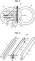
- FIG. 2 a description is provided of a construction of the fixing device 20 incorporated in the image forming apparatus 1 having the construction described above.
- FIG. 2 is a schematic vertical cross-sectional view of the fixing device 20.
- the fixing device 20 e.g., a fuser or a fusing unit
- the fixing belt 21 serving as a fixing rotator
- the pressure roller 22, serving as a pressure rotator contacts an outer circumferential surface of the fixing belt 21.
- the pressure roller 22 is rotatable in a rotation direction D22.
- a halogen heater 23A serving as a first radiant heater and a halogen heater 23B serving as a second radiant heater that heat the fixing belt 21 with radiant heat.
- a halogen heater 23A and 23B is a radiant heater serving as a main heater or a fixing heater.
- a nip formation pad 24 Inside the loop formed by the fixing belt 21 are a nip formation pad 24, a stay 25, lateral end heaters 26, a thermal conduction aid 27, and reflectors 28A and 28B.
- the components disposed inside the loop formed by the fixing belt 21, that is, the halogen heaters 23A and 23B, the nip formation pad 24, the stay 25, the lateral end heaters 26, the thermal conduction aid 27, and the reflectors 28A and 28B, may construct a belt unit 21U separably coupled with the pressure roller 22.
- the nip formation pad 24 presses against the pressure roller 22 via the fixing belt 21 to form a fixing nip N between the fixing belt 21 and the pressure roller 22.
- the nip formation pad 24 extending in a longitudinal direction thereof parallel to an axial direction of the fixing belt 21 is secured to and supported by the stay 25. Accordingly, even if the nip formation pad 24 receives pressure from the pressure roller 22, the stay 25 prevents the nip formation pad 24 from being bent by the pressure and therefore allows the nip formation pad 24 to produce a uniform nip length throughout the entire width of the pressure roller 22 in an axial direction or a longitudinal direction thereof.
- the nip formation pad 24 is made of a heat resistant material being resistant against temperatures up to 200 degrees centigrade and having an enhanced mechanical strength.
- the nip formation pad 24 is made of heat resistant resin such as polyimide (PI), polyether ether ketone (PEEK), and PI or PEEK reinforced with glass fiber.
- PI polyimide
- PEEK polyether ether ketone
- PI or PEEK reinforced with glass fiber PI or PEEK reinforced with glass fiber.
- the nip formation pad 24 is immune from thermal deformation at temperatures in a fixing temperature range desirable to fix a toner image on a sheet P, retaining the shape of the fixing nip N and quality of the toner image formed on the sheet P.
- Both lateral ends of the stay 25 and the halogen heaters 23A and 23B in a longitudinal direction thereof are secured to and supported by a pair of side plates of the fixing device 20 or a pair of holders, provided separately from the pair of side plates, respectively.
- the lateral end heaters 26 are mounted on or coupled with both lateral ends of the nip formation pad 24 in the longitudinal direction thereof, respectively.
- the lateral end heaters 26 serve as a sub heater provided separately from the main heater or the fixing heater (e.g., the halogen heaters 23A and 23B).
- the lateral end heaters 26 heat both lateral ends of the fixing belt 21 in the axial direction thereof, respectively.
- the lateral end heater 26 is a contact heater that contacts the fixing belt 21 to conduct heat to the fixing belt 21, for example, a resistive heat generator such as a ceramic heater.
- the thermal conduction aid 27 also serves as a thermal equalizer that facilitates conduction of heat in the axial direction of the fixing belt 21.
- the thermal conduction aid 27 covers a nip-side face of each of the nip formation pad 24 and the lateral end heaters 26, which is disposed opposite an inner circumferential surface of the fixing belt 21.
- the thermal conduction aid 27 conducts and equalizes heat in a longitudinal direction of the thermal conduction aid 27 that is parallel to the axial direction of the fixing belt 21, preventing heat from being stored at both lateral ends of the fixing belt 21 in the axial direction thereof while a plurality of small sheets P is conveyed over the fixing belt 21 or while the lateral end heaters 26 are turned on.
- the thermal conduction aid 27 eliminates uneven temperature of the fixing belt 21 in the axial direction thereof.
- the thermal conduction aid 27 is made of a material that conducts heat quickly, for example, a material having an enhanced thermal conductivity such as copper having a thermal conductivity of 398 W/mk and aluminum having a thermal conductivity of 236 W/mk.
- the thermal conduction aid 27 includes a nip-side face 27a being disposed opposite and in direct contact with the inner circumferential surface of the fixing belt 21, thus serving as a nip formation face that forms the fixing nip N.
- the nip-side face 27a is planar.
- the nip-side face 27a may be curved or recessed or may have other shapes.
- the nip-side face 27a is recessed with respect to the pressure roller 22, the nip-side face 27a directs a leading edge of the sheet P toward the pressure roller 22 as the sheet P is ejected from the fixing nip N, facilitating separation of the sheet P from the fixing belt 21 and suppressing jamming of the sheet P between the fixing belt 21 and the pressure roller 22.
- a temperature sensor 29 is disposed opposite the outer circumferential surface of the fixing belt 21 at a proper position thereon, for example, a position upstream from the fixing nip N in the rotation direction D21 of the fixing belt 21.
- the temperature sensor 29 detects the temperature of the fixing belt 21.
- a separator 41 is disposed downstream from the fixing nip N in the sheet conveyance direction DP to separate the sheet P from the fixing belt 21.
- a pressurization assembly presses the pressure roller 22 against the nip formation pad 24 via the fixing belt 21 and releases pressure exerted by the pressure roller 22 to the fixing belt 21.
- the fixing belt 21 that is, an endless belt being thin like film and having a downsized loop diameter, is constructed of a base layer serving as the inner circumferential surface of the fixing belt 21 and a release layer serving as the outer circumferential surface of the fixing belt 21.
- the base layer is made of metal such as nickel and SUS stainless steel or resin such as PI.
- the release layer is made of tetrafluoroethylene-perfluoroalkylvinylether copolymer (PFA), polytetrafluoroethylene (PTFE), or the like.
- PFA tetrafluoroethylene-perfluoroalkylvinylether copolymer
- PTFE polytetrafluoroethylene
- an elastic layer made of rubber such as silicone rubber, silicone rubber foam, and fluoro rubber may be interposed between the base layer and the release layer.
- the elastic layer having a thickness of 100 micrometers elastically deforms to absorb slight surface asperities of the fixing belt 21, preventing variation in gloss of the toner image on the sheet P.
- the fixing belt 21 has a total thickness not greater than 1 mm and a loop diameter in a range of from 20 mm to 40 mm.
- the fixing belt 21 is constructed of the base layer having a thickness in a range of from 20 micrometers to 50 micrometers; the elastic layer having a thickness in a range of from 100 micrometers to 300 micrometers; and the release layer having a thickness in a range of from 10 micrometers to 50 micrometers.
- the fixing belt 21 may have a total thickness not greater than 0.20 mm and preferably not greater than 0.16 mm.
- the loop diameter of the fixing belt 21 is not greater than 30 mm.
- the stay 25, having a T-shape in cross-section includes a base 25b disposed opposite the fixing nip N and an arm 25a projecting from the base 25b and being disposed opposite the nip formation pad 24 via the base 25b.
- the arm 25a of the stay 25 projects from the nip formation pad 24 in a pressurization direction PR in which the pressure roller 22 presses against the nip formation pad 24 via the fixing belt 21.
- the arm 25a is interposed between the halogen heaters 23A and 23B serving as the main heater to screen the halogen heater 23A from the halogen heater 23B.
- the halogen heater 23A includes a center heat generator disposed in a center span of the halogen heater 23A in the longitudinal direction thereof. A small sheet P is disposed opposite the center heat generator of the halogen heater 23A.
- the halogen heater 23B includes a lateral end heat generator disposed in each lateral end span of the halogen heater 23B in the longitudinal direction thereof. A large sheet P is disposed opposite the lateral end heat generator of the halogen heater 23B.
- the power supply situated inside the image forming apparatus 1 supplies power to the halogen heaters 23A and 23B so that the halogen heaters 23A and 23B generate heat.
- a controller operatively connected to the halogen heaters 23A and 23B and the temperature sensor 29 controls the halogen heaters 23A and 23B based on the temperature of the outer circumferential surface of the fixing belt 21, which is detected by the temperature sensor 29 disposed opposite the outer circumferential surface of the fixing belt 21.
- the temperature of the fixing belt 21 is adjusted to a desired fixing temperature.
- the reflector 28A is interposed between the halogen heater 23A and the stay 25.
- the reflector 28B is interposed between the halogen heater 23B and the stay 25.
- the reflectors 28A and 28B reflect light and heat radiated from the halogen heaters 23A and 23B to the reflectors 28A and 28B, respectively, toward the fixing belt 21, thus enhancing heating efficiency of the halogen heaters 23A and 23B to heat the fixing belt 21. Additionally, the reflectors 28A and 28B prevent light and heat radiated from the halogen heaters 23A and 23B from heating the stay 25 with radiant heat, suppressing waste of energy.
- an opposed face of the stay 25 disposed opposite the halogen heaters 23A and 23B may be treated with insulation or mirror finish to reflect light and heat radiated from the halogen heaters 23A and 23B to the stay 25 toward the fixing belt 21.
- the pressure roller 22 is constructed of a cored bar; an elastic layer coating the cored bar and being made of silicone rubber foam, fluoro rubber, or the like; and a release layer coating the elastic layer and being made of PFA, PTFE, or the like.
- the pressurization assembly such as a spring presses the pressure roller 22 against the fixing belt 21 to form the fixing nip N.
- the pressure roller 22 pressingly contacting the fixing belt 21 deforms the elastic layer of the pressure roller 22 at the fixing nip N formed between the pressure roller 22 and the fixing belt 21, thus defining the fixing nip N having a predetermined length in the sheet conveyance direction DP.
- a driver e.g., a motor
- the driver drives and rotates the pressure roller 22.
- a driving force of the driver is transmitted from the pressure roller 22 to the fixing belt 21 at the fixing nip N, thus rotating the fixing belt 21 in accordance with rotation of the pressure roller 22 by friction between the pressure roller 22 and the fixing belt 21.
- the driver may also be connected to the fixing belt 21 to drive and rotate the fixing belt 21.
- the fixing belt 21 rotates as the fixing belt 21 is sandwiched between the pressure roller 22 and the nip formation pad 24; in a circumferential span of the fixing belt 21 other than the nip span Na, the fixing belt 21 rotates while the fixing belt 21 is guided by flanges secured to the pair of side plates at both lateral ends of the fixing belt 21 in the axial direction thereof, respectively.
- the pressure roller 22 is a solid roller.
- the pressure roller 22 may be a hollow roller.
- a heater such as a halogen heater may be disposed inside the hollow roller.
- the elastic layer of the pressure roller 22 may be made of solid rubber.
- the elastic layer of the pressure roller 22 may be made of sponge rubber. The sponge rubber is more preferable than the solid rubber because the sponge rubber has an increased insulation that draws less heat from the fixing belt 21.
- FIG. 3 a description is provided of a construction of a nip formation unit 200 incorporated in the fixing device 20 depicted in FIG. 2 .
- FIG. 3 is a perspective view of the nip formation unit 200, illustrating a basic structure of the nip formation unit 200.
- the nip formation unit 200 includes the nip formation pad 24, the stay 25, the thermal conduction aid 27, and lateral end heaters 26a and 26b illustrated as the lateral end heaters 26 in FIG. 2 .
- the nip formation pad 24 includes a nip-side face 24c facing the fixing nip N and a stay-side face 24d being opposite the nip-side face 24c and facing the stay 25.
- the stay 25 includes a nip-side face 25c being planar and facing the fixing nip N.
- the stay-side face 24d of the nip formation pad 24 contacts the nip-side face 25c of the stay 25.
- the stay-side face 24d of the nip formation pad 24 and the nip-side face 25c of the stay 25 mount a recess and a projection (e.g., a boss and a pin), respectively, so that the stay-side face 24d engages the nip-side face 25c to restrict each other with the shape of the stay-side face 24d and the nip-side face 25c.
- the thermal conduction aid 27 engages the nip formation pad 24 that is substantially rectangular such that the thermal conduction aid 27 covers the nip-side face 24c of the nip formation pad 24 that is disposed opposite the inner circumferential surface of the fixing belt 21.
- the thermal conduction aid 27 is coupled with the nip formation pad 24.
- the thermal conduction aid 27 is coupled with the nip formation pad 24 with a claw, an adhesive, or the like.
- Two recesses 24a and 24b are disposed at both lateral ends of the nip formation pad 24 in the longitudinal direction thereof, respectively.
- the lateral end heaters 26a and 26b are secured to the recesses 24a and 24b, thus being accommodated by the recesses 24a and 24b, respectively.
- a description of a positional relation between the lateral end heaters 26a and 26b and the halogen heaters 23A and 23B is deferred.
- the thermal conduction aid 27 includes the nip-side face 27a that is disposed opposite the inner circumferential surface of the fixing belt 21.
- the nip-side face 27a serves as a slide face over which the fixing belt 21 slides.
- the nip-side face 24c of the nip formation pad 24 has a mechanical strength greater than that of the nip-side face 27a of the thermal conduction aid 27, the nip-side face 24c of the nip formation pad 24 serves as a nip formation face that faces the pressure roller 22 and forms the fixing nip N practically.
- the lateral end heaters 26a and 26b are coupled with the nip formation pad 24 to form the fixing nip N.
- the lateral end heaters 26a and 26b are situated inside a limited space inside the loop formed by the fixing belt 21, saving space.
- Each of the lateral end heaters 26a and 26b includes a nip-side face 26c disposed opposite the inner circumferential surface of the fixing belt 21.
- the nip-side face 26c of each of the lateral end heaters 26a and 26b is leveled with the nip-side face 24c of the nip formation pad 24 that is disposed opposite the inner circumferential surface of the fixing belt 21 in the pressurization direction PR depicted in FIG. 2 in which the pressure roller 22 presses against the nip formation pad 24 so that the nip-side faces 26c and the nip-side face 24c define an identical plane. Accordingly, the pressure roller 22 is pressed against the lateral end heaters 26a and 26b via the fixing belt 21 and the thermal conduction aid 27 sufficiently.
- the fixing belt 21 rotates stably in a state in which the fixing belt 21 is pressed against the lateral end heaters 26a and 26b or adhered to the lateral end heaters 26a and 26b indirectly via the thermal conduction aid 27.
- the fixing belt 21 is pressed against the lateral end heaters 26a and 26b with sufficient pressure, retaining improved heating efficiency of the lateral end heaters 26a and 26b.
- the fixing device 20 enhances reliability.
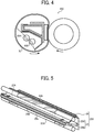
- FIG. 4 is a schematic vertical cross-sectional view of the first comparative fixing device 20C.
- the first comparative fixing device 20C includes two halogen heaters 50A and 50B that heat a fixing belt 60.
- the halogen heater 50A is a center heater that heats a center span of the fixing belt 60 in an axial direction thereof.
- the halogen heater 50B is a lateral end heater that heats a lateral end span of the fixing belt 60 in the axial direction thereof. Since the halogen heater 50A is parallel to the halogen heater 50B, one of the halogen heaters 50A and 50B may heat another one of the halogen heaters 50A and 50B with radiant heat, degrading heating efficiency of the halogen heaters 50A and 50B.
- An image forming apparatus incorporating the second comparative fixing device may form a toner image on sheets of various sizes.
- the second comparative fixing device may include a first halogen heater having a dense light distribution in a center span of the first halogen heater in a longitudinal direction thereof and a second halogen heater having a dense light distribution in each lateral end span of the second halogen heater in a longitudinal direction thereof.
- the first halogen heater and the second halogen heater are disposed inside a loop formed by the fixing belt. When a small sheet is conveyed over the fixing belt, the first halogen heater is powered on. When a large sheet greater than the small sheet is conveyed over the fixing belt, both the first halogen heater and the second halogen heater are powered on.
- the image forming apparatus incorporating the second comparative fixing device may form a toner image on an extra-large sheet (e.g., an A3 extension size sheet and a 13-inch sheet) greater than the large sheet (e.g., an A3 size sheet).
- an extra-large sheet e.g., an A3 extension size sheet and a 13-inch sheet
- the large sheet e.g., an A3 size sheet
- the second comparative fixing device may further include lateral end heaters that heat both outboard spans of the fixing belt, that are outboard from both lateral end spans of the fixing belt in the axial direction thereof.
- the outboard spans are disposed opposite the extra-large sheet.
- the lateral end heaters are disposed upstream from a fixing nip in a rotation direction of the fixing belt. The lateral end heaters contact an inner circumferential surface or an outer circumferential surface of the fixing belt.
- the lateral end heaters may melt residual toner failed to be fixed on a previous sheet at the fixing nip and therefore remaining on the fixing belt again on both outboard spans of the fixing belt in the axial direction thereof, which contact the lateral end heaters, respectively.
- the melted toner may adhere to the fixing belt and damage a toner image on a subsequent sheet, degrading quality of the toner image on the subsequent sheet.
- the lateral end heaters 26a and 26b of the fixing device 20 depicted in FIGS. 2 and 3 are disposed opposite the fixing nip N. Accordingly, the lateral end heaters 26a and 26b heat the fixing belt 21 in the nip span Na in the rotation direction D21 of the fixing belt 21.
- the lateral end heaters 26a and 26b do not heat the fixing belt 21 in the circumferential span outboard from the nip span Na in the rotation direction D21 of the fixing belt 21 unlike the lateral end heaters of the second comparative fixing device that are disposed upstream from the fixing nip in the rotation direction of the fixing belt to heat the fixing belt in a circumferential span outboard from the fixing nip in the rotation direction of the fixing belt.
- the lateral end heaters 26a and 26b of the fixing device 20 prevent residual toner failed to be fixed on a previous sheet P and therefore adhering to the fixing belt 21 from being melted again and degrading a toner image on a subsequent sheet P.
- FIG. 5 is a perspective view of the nip formation unit 200 and the halogen heaters 23A and 23B.
- the stay 25 includes a first portion 25A and a second portion 25B, each of which is substantially L-shaped in cross-section.
- the stay 25 is substantially T-shaped in cross-section. Accordingly, the stay 25 attains an enhanced rigidity that prevents the nip formation pad 24 from being bent by pressure from the pressure roller 22.
- the stay 25 constructed of the first portion 25A and the second portion 25B extends linearly in the longitudinal direction of the nip formation pad 24.
- the stay 25 is secured to the nip formation pad 24. Accordingly, the stay 25 renders the nip-side face 24c depicted in FIG. 3 of the nip formation pad 24 to form the fixing nip N precisely throughout the entire width of the fixing nip N in the longitudinal direction of the nip formation pad 24.
- the halogen heater 23A is disposed opposite the halogen heater 23B via the arm 25a of the stay 25 in a short direction perpendicular to the longitudinal direction of the stay 25.
- the arm 25a is interposed between the halogen heaters 23A and 23B to screen the halogen heater 23A from the halogen heater 23B. Accordingly, unlike the halogen heaters 50A and 50B depicted in FIG. 4 , while the halogen heaters 23A and 23B depicted in FIG. 5 are powered on, glass tubes of the halogen heaters 23A and 23B, respectively, do not heat each other, preventing degradation in heating efficiency of the halogen heaters 23A and 23B. As illustrated in FIG.
- each of the halogen heaters 23A and 23B is not surrounded by the stay 25.
- a center of each of the halogen heaters 23A and 23B in cross-section is outside a space defined or enclosed by the stay 25. Accordingly, the halogen heaters 23A and 23B attain obtuse irradiation angles ⁇ and ⁇ , respectively, of light that irradiates the fixing belt 21, thus improving heating efficiency.
- the stay 25 may have shapes other than the substantially T-shape in cross-section.
- the first portion 25A and the second portion 25B depicted in FIG. 5 may curve and extend in the longitudinal direction of the halogen heaters 23A and 23B as long as the arm 25a interposed between the halogen heaters 23A and 23B screens the halogen heater 23A from the halogen heater 23B.
- the arm 25a of each of the first portion 25A and the second portion 25B may be oblique relative to the nip-side face 24c of the nip formation pad 24.
- FIG. 6 is a diagram of the halogen heaters 23A and 23B and the lateral end heaters 26a and 26b, illustrating arrangement thereof.
- the halogen heater 23A includes a heat generator 40A serving as a center heat generator having a dense light distribution in the center span of the halogen heater 23A, which is disposed opposite a center span of the fixing belt 21 in the axial direction thereof.
- the halogen heater 23B includes a heat generator 40B serving as a lateral end heat generator having a dense light distribution in each lateral end span of the halogen heater 23B, which is disposed opposite each lateral end span of the fixing belt 21 in the axial direction thereof.
- the halogen heater 23A heats the center span of the fixing belt 21 in the axial direction thereof.
- the halogen heater 23B heats each lateral end span of the fixing belt 21 in the axial direction thereof.
- the heat generator 40A of the halogen heater 23A corresponds to small sheets P of small sizes such as an A4 size sheet in portrait orientation.
- the heat generator 40B of the halogen heater 23B corresponds to large sheets P of large sizes such as an A3 size sheet in portrait orientation.
- the heat generator 40B is disposed outboard from the heat generator 40A in the longitudinal direction of the halogen heater 23A so that the heat generator 40B heats a lateral end of the large sheet P that is outboard from the heat generator 40A in the longitudinal direction of the halogen heater 23B.
- the large sheets P include a maximum standard size sheet available in the fixing device 20.
- a heat generator 40 that is, a first combined heat generator constructed of the heat generators 40A and 40B, corresponds to a width of the maximum standard size sheet (e.g., the A3 size sheet in portrait orientation) and does not encompass a width of an extra-large sheet P of an extension size, which is greater than the width of the maximum standard size sheet in the axial direction of the fixing belt 21.
- the lateral end heaters 26a and 26b are disposed opposite both lateral ends of the halogen heater 23B in the longitudinal direction thereof, respectively.
- the lateral end heaters 26a and 26b include heat generators 42a and 42b that heat both lateral ends of the extra-large sheet P greater than the maximum standard size sheet in the longitudinal direction of the halogen heater 23B, respectively.
- a heat generator 42 that is, a second combined heat generator constructed of the heat generators 40A, 40B, 42a, and 42b, corresponds to the width of the extra-large sheet P of the extension size (e.g., the A3 extension size sheet and a 13-inch sheet).
- each of the heat generators 42a and 42b overlaps the heat generator 40B in the longitudinal direction of the halogen heater 23B. Accordingly, the fixing belt 21 of the fixing device 20 heats both lateral ends of the extra-large sheet P greater than the maximum standard size sheet in the longitudinal direction of the halogen heater 23B.
- FIG. 7 is a diagram illustrating a positional relation between the heat generator 40B of the halogen heater 23B and the heat generator 42b of the lateral end heater 26b and a heat output rate of heat output by the heat generators 40B and 42b.
- An upper part of FIG. 7 illustrates a right lateral end of the heat generator 40B of the halogen heater 23B.
- a lower part of FIG. 7 illustrates a left lateral end of the heat generator 42b of the lateral end heater 26b.
- a heat generator in which a filament is coiled helically, of a halogen heater suffers from decrease in heat output at a lateral end of the heat generator in a longitudinal direction of the halogen heater.
- the decrease in heat output varies depending on a density of the filament coiled helically. The smaller the density of the filament coiled helically is, the more the halogen heater is susceptible to the decrease in heat output. As illustrated in the upper part in FIG.
- a lateral end of the heat generator 40B in the longitudinal direction of the halogen heater 23B, which suffers from the decrease in heat output is defined as a span from a position at which the heat generator 40B attains a predetermined heat output rate of 100 percent to a position at which the heat generator 40B suffers from a decreased heat output rate of 50 percent, for example.
- the heat generator 42b includes a heat generation pattern 37.
- a lateral end of the lateral end heater 26b that is inboard from the heat generator 42b in a longitudinal direction of the lateral end heater 26b suffers from the decrease in heat output.
- the lateral end of the lateral end heater 26b in the longitudinal direction thereof fails to attain the predetermined heat output rate of 100 percent and suffers from a decreased heat output rate.
- a border Bh at which heat output from the heat generator 40B of the halogen heater 23B starts decreasing corresponds to a border Bc at which heat output from the heat generator 42b of the lateral end heater 26b starts decreasing.
- the border Bh is an outboard border disposed in proximity to an outboard lateral edge 23B1 of the halogen heater 23B in the longitudinal direction thereof.
- the border Bc is an inboard border disposed in proximity to an inboard lateral edge 26b1 of the lateral end heater 26b in the longitudinal direction thereof. Since the halogen heater 23B is spaced apart from the lateral end heater 26b as illustrated in FIG. 2 , the border Bh coincides with the border Bc in the longitudinal direction of the halogen heater 23B on a projection. Similarly, the border Bh at which heat output from another heat generator 40B of the halogen heater 23B starts decreasing corresponds to the border Bc at which heat output from the heat generator 42a of the lateral end heater 26a starts decreasing.
- the heat generator 42 depicted in FIG. 6 is immune from decrease in heat output in an overlap span where the heat generator 40B of the halogen heater 23B overlaps the lateral end heater 26a and an overlap span where the heat generator 40B of the halogen heater 23B overlaps the lateral end heater 26b in the longitudinal direction of the halogen heater 23B, thus retaining the predetermined heat output rate of 100 percent. Consequently, even when the extra-large sheet P greater than the maximum standard size sheet is conveyed over the fixing belt 21, the toner image formed on each lateral end of the extra-large sheet P in a width direction of the extra-large sheet P is fixed on the extra-large sheet P properly.
- the border Bh at which heat output from the heat generator 40B of the halogen heater 23B starts decreasing coincides with the border Bc at which heat output from the heat generator 42b of the lateral end heater 26b starts decreasing.
- the nip formation unit 200 incorporates the thermal conduction aid 27 having an enhanced thermal conductivity that offsets a certain amount of decrease in heat output from the heat generators 40B and 42b and therefore equalizes the temperature of the fixing belt 21.
- the position of the border Bc at which heat output from the heat generators 42a and 42b of the lateral end heaters 26a and 26b, respectively, starts decreasing may be determined within a predetermined allowable range.
- FIG. 8 is a graph illustrating a curve C1 that represents a heat output rate of heat output from the halogen heater 23B serving as a second radiant heater under the first pattern.
- FIG. 8 illustrates heat output from one lateral end of the halogen heater 23B in the longitudinal direction thereof.
- a vertical axis represents a heat output rate in percentage of the halogen heater 23B relative to a predetermined heat output rate.
- a horizontal axis represents the position of the halogen heater 23B in the longitudinal direction thereof.
- the graph depicted in FIG. 8 illustrates the curve C1 with a vertex like a parabola.
- the border Bc that is, the inboard lateral edge of the heat generator 42b in the longitudinal direction of the lateral end heater 26b, at which heat output from the heat generator 42b of the lateral end heater 26b starts decreasing, is situated in a border span A.
- the border span A is defined from an outboard position P1 to an inboard position P2 in the longitudinal direction of the halogen heater 23B.
- heat output from the heat generator 40B of the halogen heater 23B attains a heat output rate of 40 percent relative to a peak heat output rate.
- heat output from the heat generator 40B of the halogen heater 23B attains a heat output rate of 80 percent relative to the peak heat output rate.
- the border Bc situated in the border span A renders the heat output rate of heat output from an inboard lateral end of the lateral end heater 26b and an outboard lateral end of the halogen heater 23B in the longitudinal direction thereof to be within the predetermined allowable range.
- FIG. 9 is a graph illustrating a heat output rate of heat output from the halogen heater 23A having the heat generator 40A situated in the center span of the halogen heater 23A and a heat output rate of heat output from the halogen heater 23B having the heat generators 40B situated in each lateral end span of the halogen heater 23B under the second pattern.
- a curve CA in a dotted line represents heat output from the halogen heater 23A.
- a curve CB in a solid line represents heat output from the halogen heater 23B.
- a width W1 represents a width of an A4 size sheet in portrait orientation in the axial direction of the fixing belt 21.
- a width W2 represents a width of an A4 size sheet in landscape orientation in the axial direction of the fixing belt 21 as a width of the maximum standard size sheet.
- the halogen heaters 23A and 23B that have different light distributions in the longitudinal direction thereof and therefore have different heat output patterns provide different total heat output patterns, respectively.
- FIG. 10 is a graph illustrating a curve C2 that represents a combined heat output rate of heat output from the halogen heaters 23A and 23B under the second pattern.
- the combined heat output rate of the halogen heaters 23A and 23B attains the predetermined heat output rate of 100 percent at a position in proximity to each lateral end of the halogen heater 23B in the longitudinal direction thereof and a heat output rate of almost 100 percent in the center span of the halogen heater 23A in the longitudinal direction thereof, rendering the curve C2 to be gentle.
- a span B represents a first combined heat output span where the combined heat output rate of the halogen heaters 23A and 23B attains the heat output rate of almost 100 percent constantly.
- a span C represents a second combined heat output span where the combined heat output rate of the halogen heaters 23A and 23B attains a heat output rate in a range of from 40 percent to almost 100 percent.
- the border Bc is disposed in a border span D defined from the outboard position P1 where the halogen heater 23B attains the heat output rate of 40 percent to an inboard position P3 being inboard from the outboard position P1 in the longitudinal direction of the halogen heater 23B by the span C and one tenth of the span B.
- the border Bc situated in the border span D renders the heat output rate of the inboard lateral end of the lateral end heater 26b and the outboard lateral end of the halogen heater 23B in the longitudinal direction thereof to be within the predetermined allowable range.
- FIG. 11 is a graph illustrating a curve C3 that represents a combined heat output rate of heat output from the halogen heaters 23A and 23B under the third pattern as a variation.
- a center part C3c of the curve C3 is gentle.
- Both lateral end parts C3e of the curve C3 indicate a heat output rate greater than a heat output rate indicated by the center part C3c.
- the curve C3 is obtained with the filament of each of the heat generators 40B of the halogen heater 23B, which is coiled more densely than the filament of the heat generator 40A of the halogen heater 23A.
- a span B' represents a span where the combined heat output rate of the halogen heaters 23A and 23B attains the heat output rate of almost 100 percent.
- the span B' bridges the lateral end parts C3e.
- the span C represents the span where the combined heat output rate of the halogen heaters 23A and 23B attains the heat output rate in the range of from 40 percent to almost 100 percent.
- the border Bc is disposed in a border span D' defined from the outboard position P1 where the halogen heater 23B attains the heat output rate of 40 percent to an inboard position P3' being inboard from the outboard position P1 in the longitudinal direction of the halogen heater 23B by the span C and one tenth of the span B'.
- the border Bc situated in the border span D' renders the heat output rate of the inboard lateral end of the lateral end heater 26b and the outboard lateral end of the halogen heater 23B in the longitudinal direction thereof to be within the predetermined allowable range.
- the thermal conduction aid 27 may increase a coefficient of friction between the fixing belt 21 and the thermal conduction aid 27. As the coefficient of friction increases, a unit torque of the fixing device 20 may increase, shortening a life of the fixing device 20.
- the thermal conduction aid 27 incorporates the nip-side face 27a being disposed opposite and in contact with the fixing belt 21 such that the fixing belt 21 slides over the nip-side face 27a.
- the nip-side face 27a is smooth and treated with processing to reduce friction.
- the nip-side face 27a is coated with a fluorine material such as PFA and PTFE or treated with other coating to reduce friction between the thermal conduction aid 27 and the inner circumferential surface of the fixing belt 21.
- a lubricant such as fluorine grease and silicone oil is applied between the thermal conduction aid 27 and the inner circumferential surface of the fixing belt 21 to reduce friction further.
- the nip-side face 27a is applied with the lubricant.
- a contact sensor (e.g., a thermistor) is employed to detect the temperature of the fixing belt 21 precisely at reduced costs.
- the contact sensor may produce slight scratches at a contact position on the fixing belt 21 where the contact sensor contacts the fixing belt 21.
- the slight scratches may damage a toner image formed on a sheet P while the sheet P is conveyed over the fixing belt 21, generating slight variation in gloss of the toner image on the sheet P or the like.
- the contact sensor is not situated within a conveyance span in the axial direction of the fixing belt 21 where the maximum standard size sheet is conveyed over the fixing belt 21.
- the extra-large sheet P that is, an extension size sheet
- the extra-large sheet P includes an extension portion used as an edge or a margin abutting on a toner image formed in proximity to a lateral edge of the maximum standard size sheet, a portion where a linear image called a trim mark used for alignment in printing positions is formed, or a portion where a solid patch having a small area for color adjustment is formed.
- the extension portion is often trimmed.
- the contact sensor produces scratches on the fixing belt 21 and the scratches damage a toner image formed on the extension portion of the extra-large sheet P with slight variation in gloss of the toner image or the like, the damaged toner image does not appear on the extra-large sheet P as a faulty toner image after the extension portion is trimmed.
- the fixing device 20 includes a plurality of temperature detectors 45a and 45b, disposed opposite both lateral ends of the fixing belt 21 in the axial direction thereof, to detect the temperature of both lateral ends of the fixing belt 21 that are heated by the lateral end heaters 26a and 26b, respectively.
- FIG. 12 is a plan view of the temperature detector 45b and the fixing belt 21.
- FIG. 12 omits illustration of the temperature detector 45a disposed symmetrical with the temperature detector 45b.
- Each of the temperature detectors 45a and 45b is disposed opposite the outer circumferential surface of the fixing belt 21 and disposed outboard from the conveyance span of the maximum standard size sheet in the axial direction of the fixing belt 21.
- Each of the temperature detectors 45a and 45b is disposed within a span W being outboard from a lateral edge of the maximum standard size sheet and inboard from a lateral edge of the extra-large sheet P greater than the maximum standard size sheet in the axial direction of the fixing belt 21.
- each of the temperature detectors 45a and 45b is disposed outboard from the heat generator 40 depicted in FIG. 6 and inboard from a lateral edge of the heat generator 42 in the axial direction of the fixing belt 21.
- the temperature detectors 45a and 45b detect the temperature of both lateral ends of the fixing belt 21 that are heated by the lateral end heaters 26a and 26b, respectively, precisely at reduced costs while preventing a faulty toner image that suffers from slight variation in gloss or the like from appearing on the extra-large sheet P.
- FIG. 12 illustrates the width W2 of the A4 size sheet in landscape orientation in the axial direction of the fixing belt 21 as the width of the maximum standard size sheet and a width W3 of the extra-large sheet P in the axial direction of the fixing belt 21 as a width of a maximum extension size sheet.
- the fixing device 20 may include a sensor that detects the temperature of a part of the lateral end heaters 26a and 26b so that the controller controls the lateral end heaters 26a and 26b based on the temperature of the lateral end heaters 26a and 26b that is detected by the sensor.
- a fixing device e.g., the fixing device 20
- an endless belt e.g., the fixing belt 21
- a pressure rotator e.g., the pressure roller 22
- a plurality of radiant heaters e.g., the halogen heaters 23A and 23B having different light distributions in an axial direction of the endless belt, respectively, is disposed inside the loop formed by the endless belt.
- a first radiant heater (e.g., the halogen heater 23A) includes a first heat generator (e.g., the heat generator 40A) that heats the endless belt.
- a second radiant heater (e.g., the halogen heater 23B) includes a second heat generator (e.g., the heat generator 40B) that heats the endless belt and is disposed outboard from the first heat generator in the axial direction of the endless belt.
- a nip formation pad (e.g., the nip formation pad 24) is disposed inside the loop formed by the endless belt.
- the nip formation pad forms a fixing nip (e.g., the fixing nip N) between the endless belt and the pressure rotator.
- a stay (e.g., the stay 25) supports the nip formation pad and is interposed between the first radiant heater and the second radiant heater to screen the first radiant heater from the second radiant heater.
- a contact heater (e.g., the lateral end heaters 26a and 26b) is disposed at least at one lateral end of the nip formation pad in a longitudinal direction thereof.
- the contact heater heats at least one lateral end of the endless belt in the axial direction thereof.
- the nip formation pad includes a nip-side face (e.g., the nip-side face 24c) disposed opposite the endless belt.
- the contact heater includes a nip-side face (e.g., the nip-side face 26c) disposed opposite the endless belt.
- a thermal conduction aid (e.g., the thermal conduction aid 27) covers the nip-side face of the nip formation pad and the nip-side face of the contact heater.
- the thermal conduction aid conducts heat applied to the endless belt in the axial direction of the endless belt.
- the stay screens the first radiant heater from the second radiant heater, the stay prevents the first radiant heater and the second radiant heater from heating each other, thus improving heating efficiency of the first radiant heater and the second radiant heater.
- the contact heater is disposed at least at one lateral end of the nip formation pad in the longitudinal direction thereof.
- the contact heater heats at least one lateral end of the endless belt in the axial direction thereof. Accordingly, the contact heater heats recording media of special sizes (e.g., an extra-large sheet) through the endless belt, improving quality of a toner image formed on the recording media and reliability of the fixing device.
- the fixing device 20 employs a center conveyance system in which the sheet P is centered on the fixing belt 21 in the axial direction thereof.
- the fixing device 20 may employ a lateral end conveyance system in which the sheet P is conveyed in the sheet conveyance direction DP along one lateral end of the fixing belt 21 in the axial direction thereof.
- one of the heat generators 40B of the halogen heater 23B and one of the lateral end heaters 26a and 26b are eliminated.
- Another one of the heat generators 40B of the halogen heater 23B and another one of the lateral end heaters 26a and 26b are distal from the one lateral end of the fixing belt 21 in the axial direction thereof.
- the fixing belt 21 serves as an endless belt.
- a fixing film, a fixing sleeve, or the like may be used as an endless belt.
- the pressure roller 22 serves as a pressure rotator.
- a pressure belt or the like may be used as a pressure rotator.
Landscapes
- Physics & Mathematics (AREA)
- General Physics & Mathematics (AREA)
- Fixing For Electrophotography (AREA)
Abstract
Description
- Exemplary aspects of the present disclosure relate to a fixing device and an image forming apparatus, and more particularly, to a fixing device for fixing a toner image on a recording medium and an image forming apparatus incorporating the fixing device.
- Related-art image forming apparatuses, such as copiers, facsimile machines, printers, or multifunction printers having two or more of copying, printing, scanning, facsimile, plotter, and other functions, typically form an image on a recording medium according to image data. Thus, for example, a charger uniformly charges a surface of a photoconductor; an optical writer emits a light beam onto the charged surface of the photoconductor to form an electrostatic latent image on the photoconductor according to the image data; a developing device supplies toner to the electrostatic latent image formed on the photoconductor to render the electrostatic latent image visible as a toner image; the toner image is directly transferred from the photoconductor onto a recording medium or is indirectly transferred from the photoconductor onto a recording medium via an intermediate transfer belt; finally, a fixing device applies heat and pressure to the recording medium bearing the toner image to fix the toner image on the recording medium, thus forming the image on the recording medium.
- Such fixing device may include a fixing rotator, such as a fixing roller, a fixing belt (e.g., an endless belt), and a fixing film, heated by a heater and a pressure rotator, such as a pressure roller and a pressure belt, pressed against the fixing rotator to form a fixing nip therebetween through which a recording medium bearing a toner image is conveyed. As the recording medium bearing the toner image is conveyed through the fixing nip, the fixing rotator and the pressure rotator apply heat and pressure to the recording medium, melting and fixing the toner image on the recording medium.
- The fixing device may fix a toner image on sheets of various sizes. If the fixing device includes the heater having a width that is equivalent to a width of a large sheet, even when a plurality of small sheets is conveyed over the fixing belt continuously, the heater may heat a non-conveyance span of the fixing belt where the small sheets are not conveyed. Accordingly, the non-conveyance span, situated at each lateral end of the fixing belt in an axial direction thereof, may overheat.
- To address this circumstance, the fixing device may include a first halogen heater having a dense light distribution in a center span of the first halogen heater in a longitudinal direction thereof and a second halogen heater having a dense light distribution in each lateral end span of the second halogen heater in a longitudinal direction thereof. The first halogen heater and the second halogen heater are disposed inside a loop formed by the fixing belt. When a small sheet is conveyed over the fixing belt, the first halogen heater is powered on. When a large sheet greater than the small sheet is conveyed over the fixing belt, both the first halogen heater and the second halogen heater are powered on.
- However, since the first halogen heater is parallel to the second halogen heater, one of the first halogen heater and the second halogen heater may heat another one of the first halogen heater and the second halogen heater with radiant heat, degrading heating efficiency of the first halogen heater and the second halogen heater to heat the fixing belt.
- Additionally, the fixing device may fix a toner image on an extra-large sheet (e.g., an A3 extension size sheet and a 13-inch sheet) greater than the large sheet (e.g., an A3 size sheet).
- To address this circumstance, as disclosed by
JP-2014-178370-A - If the lateral end heaters press against the fixing belt with increased pressure to enhance heat conduction efficiency of heat conducted from the lateral end heaters to the fixing belt, the lateral end heaters contact the fixing belt with an increased friction therebetween, degrading rotation of the fixing belt and reliability.
- Conversely, if the lateral end heaters contact the fixing belt with decreased pressure to improve rotation of the fixing belt, the lateral end heaters may heat the fixing belt insufficiently. Accordingly, the lateral end heaters may overheat, degrading reliability.
- Additionally, the lateral end heaters may melt residual toner failed to be fixed on a previous sheet at the fixing nip and therefore remaining on the fixing belt again on both outboard spans of the fixing belt in the axial direction thereof, which contact the lateral end heaters, respectively. The melted toner may adhere to the fixing belt and damage a toner image on a subsequent sheet, degrading quality of the toner image on the subsequent sheet.
- It is a general object of the present disclosure to provide an improved and useful fixing device in which the above-mentioned problems are eliminated. In order to achieve the above-mentioned object, there is provided a fixing device according to claim 1. Advantageous embodiments are defined by the dependent claims. Advantageously, the fixing device includes an endless belt that is flexible and formed into a loop and a pressure rotator disposed opposite an outer circumferential surface of the endless belt. A first radiant heater is disposed inside the loop formed by the endless belt. The first radiant heater includes a first heat generator to heat the endless belt. A second radiant heater is disposed inside the loop formed by the endless belt. The second radiant heater includes a second heat generator, disposed outboard from the first heat generator in an axial direction of the endless belt, to heat the endless belt. A nip formation pad, disposed inside the loop formed by the endless belt, forms a fixing nip between the endless belt and the pressure rotator. The nip formation pad includes a nip-side face disposed opposite the endless belt. A contact heater, disposed at least at one lateral end of the nip formation pad in a longitudinal direction of the nip formation pad, heats at least one lateral end of the endless belt in the axial direction of the endless belt. The contact heater includes a nip-side face disposed opposite the endless belt. A thermal conduction aid, covering the nip-side face of the nip formation pad and the nip-side face of the contact heater, conducts heat applied to the endless belt in the axial direction of the endless belt.
- Accordingly, the first radiant heater and the second radiant heater heat the endless belt effectively. Additionally, the contact heater heats the at least one lateral end of the endless belt to heat recording media of special sizes (e.g., an extra-large sheet), improving quality of a toner image formed on the recording media and reliability of the fixing device.
- Advantageously, an image forming apparatus includes the fixing device described above.
- A more complete appreciation of the embodiments and many of the attendant advantages and features thereof can be readily obtained and understood from the following detailed description with reference to the accompanying drawings, wherein:
-
FIG. 1 is a schematic vertical cross-sectional view of an image forming apparatus according to an exemplary embodiment of the present disclosure; -
FIG. 2 is a vertical cross-sectional view of a fixing device incorporated in the image forming apparatus depicted inFIG. 1 ; -
FIG. 3 is a perspective view of a nip formation unit incorporated in the fixing device depicted inFIG. 2 ; -
FIG. 4 is a schematic vertical cross-sectional view of a first comparative fixing device; -
FIG. 5 is a perspective view of the nip formation unit depicted inFIG. 3 and halogen heaters incorporated in the fixing device depicted inFIG. 2 ; -
FIG. 6 is a diagram of the halogen heaters depicted inFIG. 5 and lateral end heaters incorporated in the nip formation unit depicted inFIG. 3 ; -
FIG. 7 is a diagram illustrating a positional relation between a heat generator of the halogen heater and a heat generator of the lateral end heater depicted inFIG. 6 and a heat output rate of heat output from the heat generators; -
FIG. 8 is a graph illustrating a curve that represents a heat output rate of heat output from the halogen heater depicted inFIG. 6 under a first pattern; -
FIG. 9 is a graph illustrating curves that represent a heat output rate of heat output from the halogen heaters depicted inFIG. 6 under a second pattern; -
FIG. 10 is a graph illustrating a curve that represents a combined heat output rate of heat output from the halogen heaters depicted inFIG. 6 under the second pattern; -
FIG. 11 is a graph illustrating a curve that represents a combined heat output rate of heat output from the halogen heaters depicted inFIG. 6 under a third pattern; and -
FIG. 12 is a plan view of a temperature detector and a fixing belt incorporated in the fixing device depicted inFIG. 2 . - In describing embodiments illustrated in the drawings, specific terminology is employed for the sake of clarity. However, the disclosure of this specification is not intended to be limited to the specific terminology so selected and it is to be understood that each specific element includes all technical equivalents that have a similar function, operate in a similar manner, and achieve a similar result.
- As used herein, the singular forms "a", "an", and "the" are intended to include the plural forms as well, unless the context clearly indicates otherwise.
- Referring now to the drawings, wherein like reference numerals designate identical or corresponding parts throughout the several views, particularly to
FIG. 1 , an image forming apparatus 1 according to an exemplary embodiment is explained. -
FIG. 1 is a schematic vertical cross-sectional view of the image forming apparatus 1. The image forming apparatus 1 may be a copier, a facsimile machine, a printer, a multifunction peripheral or a multifunction printer (MFP) having at least one of copying, printing, scanning, facsimile, and plotter functions, or the like. According to this exemplary embodiment, the image forming apparatus 1 is a color printer that forms color and monochrome toner images on a recording medium by electrophotography. Alternatively, the image forming apparatus 1 may be a monochrome printer that forms a monochrome toner image on a recording medium. - Referring to
FIG. 1 , a description is provided of a construction of the image forming apparatus 1. - As illustrated in
FIG. 1 , the image forming apparatus 1 is a color laser printer including fourimage forming devices image forming devices intermediate transfer belt 30 is stretched. Although theimage forming devices image forming devices - For example, each of the
image forming devices FIG. 1 illustrates reference numerals assigned to the photoconductor 5, the charger 6, the developing device 7, and the cleaner 8 of theimage forming device 4K that forms a black toner image. However, reference numerals for theimage forming devices - Below the
image forming devices - Above the
image forming devices transfer device 3. For example, thetransfer device 3 includes theintermediate transfer belt 30 serving as a transferred image bearer, fourprimary transfer rollers 31 serving as primary transferors, and asecondary transfer roller 36 serving as a secondary transferor. Thetransfer device 3 further includes a secondarytransfer backup roller 32, a cleaningbackup roller 33, atension roller 34, and abelt cleaner 35. - The
intermediate transfer belt 30 is an endless belt stretched taut across the secondarytransfer backup roller 32, the cleaningbackup roller 33, and thetension roller 34. As a driver drives and rotates the secondarytransfer backup roller 32 counterclockwise inFIG. 1 , the secondarytransfer backup roller 32 rotates theintermediate transfer belt 30 counterclockwise inFIG. 1 in a rotation direction D30 by friction therebetween. - The four
primary transfer rollers 31 sandwich theintermediate transfer belt 30 together with the four photoconductors 5, forming four primary transfer nips between theintermediate transfer belt 30 and the photoconductors 5, respectively. Theprimary transfer rollers 31 are coupled to a power supply disposed inside the image forming apparatus 1. The power supply applies at least one of a predetermined direct current (DC) voltage and a predetermined alternating current (AC) voltage to each of theprimary transfer rollers 31. - The
secondary transfer roller 36 sandwiches theintermediate transfer belt 30 together with the secondarytransfer backup roller 32, forming a secondary transfer nip between thesecondary transfer roller 36 and theintermediate transfer belt 30. Similar to theprimary transfer rollers 31, thesecondary transfer roller 36 is coupled to the power supply disposed inside the image forming apparatus 1. The power supply applies at least one of a predetermined direct current (DC) voltage and a predetermined alternating current (AC) voltage to thesecondary transfer roller 36. - The
belt cleaner 35 includes a cleaning brush and a cleaning blade that contact an outer circumferential surface of theintermediate transfer belt 30. - A bottle holder 2 situated in an upper portion of the image forming apparatus 1 accommodates four
toner bottles toner bottles image forming devices toner bottles toner bottles - In a lower portion of the image forming apparatus 1 are a
paper tray 10 that loads a plurality of sheets P serving as recording media and afeed roller 11 that picks up and feeds a sheet P from thepaper tray 10 toward the secondary transfer nip formed between thesecondary transfer roller 36 and theintermediate transfer belt 30. The sheets P may be thick paper, postcards, envelopes, plain paper, thin paper, coated paper, art paper, tracing paper, overhead projector (OHP) transparencies, and the like. Optionally, a bypass tray that loads thick paper, postcards, envelopes, thin paper, coated paper, art paper, tracing paper, OHP transparencies, and the like may be attached to the image forming apparatus 1. - A conveyance path R extends from the
feed roller 11 to anoutput roller pair 13 to convey the sheet P picked up from thepaper tray 10 onto an outside of the image forming apparatus 1 through the secondary transfer nip. The conveyance path R is provided with aregistration roller pair 12 located below the secondary transfer nip formed between thesecondary transfer roller 36 and theintermediate transfer belt 30, that is, upstream from the secondary transfer nip in a sheet conveyance direction DP. Theregistration roller pair 12 serving as a conveyor conveys the sheet P conveyed from thefeed roller 11 toward the secondary transfer nip. - The conveyance path R is further provided with a fixing
device 20 located above the secondary transfer nip, that is, downstream from the secondary transfer nip in the sheet conveyance direction DP. The fixingdevice 20 fixes an unfixed toner image, which is transferred from theintermediate transfer belt 30 onto the sheet P, on the sheet P. The conveyance path R is further provided with theoutput roller pair 13 located above the fixingdevice 20, that is, downstream from the fixingdevice 20 in the sheet conveyance direction DP. Theoutput roller pair 13 ejects the sheet P bearing the fixed toner image onto the outside of the image forming apparatus 1, that is, anoutput tray 14 disposed atop the image forming apparatus 1. Theoutput tray 14 stocks the sheet P ejected by theoutput roller pair 13. - Referring to
FIG. 1 , a description is provided of an image forming operation performed by the image forming apparatus 1 having the construction described above to form a full color toner image on a sheet P. - As a print job starts, a driver drives and rotates the photoconductors 5 of the
image forming devices FIG. 1 in a rotation direction D5. The chargers 6 uniformly charge the outer circumferential surface of the respective photoconductors 5 at a predetermined polarity. The exposure device 9 emits laser beams onto the charged outer circumferential surface of the respective photoconductors 5 according to yellow, cyan, magenta, and black image data constructing color image data sent from the external device, respectively, thus forming electrostatic latent images on the photoconductors 5. The image data used to expose the respective photoconductors 5 is monochrome image data produced by decomposing a desired full color image into yellow, cyan, magenta, and black image data. The developing devices 7 supply yellow, cyan, magenta, and black toners to the electrostatic latent images formed on the photoconductors 5, visualizing the electrostatic latent images as yellow, cyan, magenta, and black toner images, respectively. - Simultaneously, as the print job starts, the secondary
transfer backup roller 32 is driven and rotated counterclockwise inFIG. 1 , rotating theintermediate transfer belt 30 in the rotation direction D30 by friction therebetween. The power supply applies a constant voltage or a constant current control voltage having a polarity opposite a polarity of the charged toner to theprimary transfer rollers 31, creating a transfer electric field at each of the primary transfer nips formed between the photoconductors 5 and theprimary transfer rollers 31, respectively. - When the yellow, cyan, magenta, and black toner images formed on the photoconductors 5 reach the primary transfer nips, respectively, in accordance with rotation of the photoconductors 5, the yellow, cyan, magenta, and black toner images are primarily transferred from the photoconductors 5 onto the
intermediate transfer belt 30 by the transfer electric field created at the primary transfer nips such that the yellow, cyan, magenta, and black toner images are superimposed successively on a same position on theintermediate transfer belt 30. Thus, a full color toner image is formed on the outer circumferential surface of theintermediate transfer belt 30. After the primary transfer of the yellow, cyan, magenta, and black toner images from the photoconductors 5 onto theintermediate transfer belt 30, the cleaners 8 remove residual toner failed to be transferred onto theintermediate transfer belt 30 and therefore remaining on the photoconductors 5 therefrom, respectively. Thereafter, dischargers discharge the outer circumferential surface of the respective photoconductors 5, initializing the surface potential thereof. - On the other hand, the
feed roller 11 disposed in the lower portion of the image forming apparatus 1 is driven and rotated to feed a sheet P from thepaper tray 10 toward theregistration roller pair 12 through the conveyance path R. Theregistration roller pair 12 conveys the sheet P sent to the conveyance path R by thefeed roller 11 to the secondary transfer nip formed between thesecondary transfer roller 36 and theintermediate transfer belt 30 at a proper time. Thesecondary transfer roller 36 is applied with a transfer voltage having a polarity opposite a polarity of the charged yellow, cyan, magenta, and black toners constructing the full color toner image formed on theintermediate transfer belt 30, thus creating a transfer electric field at the secondary transfer nip. - As the yellow, cyan, magenta, and black toner images constructing the full color toner image on the
intermediate transfer belt 30 reach the secondary transfer nip in accordance with rotation of theintermediate transfer belt 30, the transfer electric field created at the secondary transfer nip secondarily transfers the yellow, cyan, magenta, and black toner images from theintermediate transfer belt 30 onto the sheet P collectively. After the secondary transfer of the full color toner image from theintermediate transfer belt 30 onto the sheet P, thebelt cleaner 35 removes residual toner failed to be transferred onto the sheet P and therefore remaining on theintermediate transfer belt 30 therefrom. The removed toner is conveyed and collected into a waste toner container situated inside the image forming apparatus 1. - Thereafter, the sheet P bearing the full color toner image is conveyed to the fixing
device 20 that fixes the full color toner image on the sheet P. The sheet P bearing the fixed full color toner image is ejected by theoutput roller pair 13 onto the outside of the image forming apparatus 1, that is, theoutput tray 14 that stocks the sheet P. - The above describes the image forming operation of the image forming apparatus 1 to form the full color toner image on the sheet P. Alternatively, the image forming apparatus 1 may form a monochrome toner image by using any one of the four
image forming devices image forming devices - Referring to
FIG. 2 , a description is provided of a construction of the fixingdevice 20 incorporated in the image forming apparatus 1 having the construction described above. -
FIG. 2 is a schematic vertical cross-sectional view of the fixingdevice 20. The fixing device 20 (e.g., a fuser or a fusing unit) includes a fixingbelt 21 and apressure roller 22. The fixingbelt 21, serving as a fixing rotator, is an endless belt that is thin, flexible, tubular, and rotatable in a rotation direction D21. Thepressure roller 22, serving as a pressure rotator, contacts an outer circumferential surface of the fixingbelt 21. Thepressure roller 22 is rotatable in a rotation direction D22. Inside a loop formed by the fixingbelt 21 is a plurality of heaters or a plurality of fixing heaters, that is, ahalogen heater 23A serving as a first radiant heater and ahalogen heater 23B serving as a second radiant heater that heat the fixingbelt 21 with radiant heat. Each of thehalogen heaters - Inside the loop formed by the fixing
belt 21 are anip formation pad 24, astay 25,lateral end heaters 26, athermal conduction aid 27, andreflectors belt 21, that is, thehalogen heaters nip formation pad 24, thestay 25, thelateral end heaters 26, thethermal conduction aid 27, and thereflectors belt unit 21U separably coupled with thepressure roller 22. - The
nip formation pad 24 presses against thepressure roller 22 via the fixingbelt 21 to form a fixing nip N between the fixingbelt 21 and thepressure roller 22. Thestay 25, serving as a support, supports thenip formation pad 24. - A detailed description is now given of a configuration of the
nip formation pad 24. - The
nip formation pad 24 extending in a longitudinal direction thereof parallel to an axial direction of the fixingbelt 21 is secured to and supported by thestay 25. Accordingly, even if thenip formation pad 24 receives pressure from thepressure roller 22, thestay 25 prevents thenip formation pad 24 from being bent by the pressure and therefore allows thenip formation pad 24 to produce a uniform nip length throughout the entire width of thepressure roller 22 in an axial direction or a longitudinal direction thereof. Thenip formation pad 24 is made of a heat resistant material being resistant against temperatures up to 200 degrees centigrade and having an enhanced mechanical strength. For example, thenip formation pad 24 is made of heat resistant resin such as polyimide (PI), polyether ether ketone (PEEK), and PI or PEEK reinforced with glass fiber. Thus, thenip formation pad 24 is immune from thermal deformation at temperatures in a fixing temperature range desirable to fix a toner image on a sheet P, retaining the shape of the fixing nip N and quality of the toner image formed on the sheet P. Both lateral ends of thestay 25 and thehalogen heaters device 20 or a pair of holders, provided separately from the pair of side plates, respectively. - A detailed description is now given of a configuration of the
lateral end heaters 26. - The
lateral end heaters 26 are mounted on or coupled with both lateral ends of thenip formation pad 24 in the longitudinal direction thereof, respectively. Thelateral end heaters 26 serve as a sub heater provided separately from the main heater or the fixing heater (e.g., thehalogen heaters lateral end heaters 26 heat both lateral ends of the fixingbelt 21 in the axial direction thereof, respectively. Thelateral end heater 26 is a contact heater that contacts the fixingbelt 21 to conduct heat to the fixingbelt 21, for example, a resistive heat generator such as a ceramic heater. - A detailed description is now given of a configuration of the
thermal conduction aid 27. - The
thermal conduction aid 27 also serves as a thermal equalizer that facilitates conduction of heat in the axial direction of the fixingbelt 21. Thethermal conduction aid 27 covers a nip-side face of each of thenip formation pad 24 and thelateral end heaters 26, which is disposed opposite an inner circumferential surface of the fixingbelt 21. Thethermal conduction aid 27 conducts and equalizes heat in a longitudinal direction of thethermal conduction aid 27 that is parallel to the axial direction of the fixingbelt 21, preventing heat from being stored at both lateral ends of the fixingbelt 21 in the axial direction thereof while a plurality of small sheets P is conveyed over the fixingbelt 21 or while thelateral end heaters 26 are turned on. Thus, thethermal conduction aid 27 eliminates uneven temperature of the fixingbelt 21 in the axial direction thereof. Hence, thethermal conduction aid 27 is made of a material that conducts heat quickly, for example, a material having an enhanced thermal conductivity such as copper having a thermal conductivity of 398 W/mk and aluminum having a thermal conductivity of 236 W/mk. - The
thermal conduction aid 27 includes a nip-side face 27a being disposed opposite and in direct contact with the inner circumferential surface of the fixingbelt 21, thus serving as a nip formation face that forms the fixing nip N. As illustrated inFIG. 2 , the nip-side face 27a is planar. Alternatively, the nip-side face 27a may be curved or recessed or may have other shapes. If the nip-side face 27a is recessed with respect to thepressure roller 22, the nip-side face 27a directs a leading edge of the sheet P toward thepressure roller 22 as the sheet P is ejected from the fixing nip N, facilitating separation of the sheet P from the fixingbelt 21 and suppressing jamming of the sheet P between the fixingbelt 21 and thepressure roller 22. - A
temperature sensor 29 is disposed opposite the outer circumferential surface of the fixingbelt 21 at a proper position thereon, for example, a position upstream from the fixing nip N in the rotation direction D21 of the fixingbelt 21. Thetemperature sensor 29 detects the temperature of the fixingbelt 21. Aseparator 41 is disposed downstream from the fixing nip N in the sheet conveyance direction DP to separate the sheet P from the fixingbelt 21. A pressurization assembly presses thepressure roller 22 against thenip formation pad 24 via the fixingbelt 21 and releases pressure exerted by thepressure roller 22 to the fixingbelt 21. - A detailed description is now given of a construction of the fixing
belt 21. - In order to decrease a thermal capacity of the fixing
belt 21, the fixingbelt 21, that is, an endless belt being thin like film and having a downsized loop diameter, is constructed of a base layer serving as the inner circumferential surface of the fixingbelt 21 and a release layer serving as the outer circumferential surface of the fixingbelt 21. The base layer is made of metal such as nickel and SUS stainless steel or resin such as PI. The release layer is made of tetrafluoroethylene-perfluoroalkylvinylether copolymer (PFA), polytetrafluoroethylene (PTFE), or the like. Optionally, an elastic layer made of rubber such as silicone rubber, silicone rubber foam, and fluoro rubber may be interposed between the base layer and the release layer. While the fixingbelt 21 and thepressure roller 22 pressingly sandwich the unfixed toner image on the sheet P to fix the toner image on the sheet P, the elastic layer having a thickness of 100 micrometers elastically deforms to absorb slight surface asperities of the fixingbelt 21, preventing variation in gloss of the toner image on the sheet P. - In order to decrease the thermal capacity of the fixing
belt 21, the fixingbelt 21 has a total thickness not greater than 1 mm and a loop diameter in a range of from 20 mm to 40 mm. For example, the fixingbelt 21 is constructed of the base layer having a thickness in a range of from 20 micrometers to 50 micrometers; the elastic layer having a thickness in a range of from 100 micrometers to 300 micrometers; and the release layer having a thickness in a range of from 10 micrometers to 50 micrometers. In order to decrease the thermal capacity of the fixingbelt 21 further, the fixingbelt 21 may have a total thickness not greater than 0.20 mm and preferably not greater than 0.16 mm. The loop diameter of the fixingbelt 21 is not greater than 30 mm. - A detailed description is now given of a construction of the
stay 25. - The
stay 25, having a T-shape in cross-section, includes abase 25b disposed opposite the fixing nip N and anarm 25a projecting from thebase 25b and being disposed opposite thenip formation pad 24 via thebase 25b. In other words, thearm 25a of thestay 25 projects from thenip formation pad 24 in a pressurization direction PR in which thepressure roller 22 presses against thenip formation pad 24 via the fixingbelt 21. Thearm 25a is interposed between thehalogen heaters halogen heater 23A from thehalogen heater 23B. - A detailed description is now given of a construction of the
halogen heaters - The
halogen heater 23A includes a center heat generator disposed in a center span of thehalogen heater 23A in the longitudinal direction thereof. A small sheet P is disposed opposite the center heat generator of thehalogen heater 23A. Thehalogen heater 23B includes a lateral end heat generator disposed in each lateral end span of thehalogen heater 23B in the longitudinal direction thereof. A large sheet P is disposed opposite the lateral end heat generator of thehalogen heater 23B. The power supply situated inside the image forming apparatus 1 supplies power to thehalogen heaters halogen heaters halogen heaters temperature sensor 29 controls thehalogen heaters belt 21, which is detected by thetemperature sensor 29 disposed opposite the outer circumferential surface of the fixingbelt 21. Thus, the temperature of the fixingbelt 21 is adjusted to a desired fixing temperature. - A detailed description is now given of a configuration of the
reflectors - The
reflector 28A is interposed between thehalogen heater 23A and thestay 25. Thereflector 28B is interposed between thehalogen heater 23B and thestay 25. Thereflectors halogen heaters reflectors belt 21, thus enhancing heating efficiency of thehalogen heaters belt 21. Additionally, thereflectors halogen heaters stay 25 with radiant heat, suppressing waste of energy. Alternatively, instead of thereflectors stay 25 disposed opposite thehalogen heaters halogen heaters stay 25 toward the fixingbelt 21. - A detailed description is now given of a construction of the
pressure roller 22. - The
pressure roller 22 is constructed of a cored bar; an elastic layer coating the cored bar and being made of silicone rubber foam, fluoro rubber, or the like; and a release layer coating the elastic layer and being made of PFA, PTFE, or the like. The pressurization assembly such as a spring presses thepressure roller 22 against the fixingbelt 21 to form the fixing nip N. Thepressure roller 22 pressingly contacting the fixingbelt 21 deforms the elastic layer of thepressure roller 22 at the fixing nip N formed between thepressure roller 22 and the fixingbelt 21, thus defining the fixing nip N having a predetermined length in the sheet conveyance direction DP. A driver (e.g., a motor) disposed inside the image forming apparatus 1 depicted inFIG. 1 drives and rotates thepressure roller 22. As the driver drives and rotates thepressure roller 22, a driving force of the driver is transmitted from thepressure roller 22 to the fixingbelt 21 at the fixing nip N, thus rotating the fixingbelt 21 in accordance with rotation of thepressure roller 22 by friction between thepressure roller 22 and the fixingbelt 21. Alternatively, the driver may also be connected to the fixingbelt 21 to drive and rotate the fixingbelt 21. In a nip span Na of the fixing nip N, the fixingbelt 21 rotates as the fixingbelt 21 is sandwiched between thepressure roller 22 and thenip formation pad 24; in a circumferential span of the fixingbelt 21 other than the nip span Na, the fixingbelt 21 rotates while the fixingbelt 21 is guided by flanges secured to the pair of side plates at both lateral ends of the fixingbelt 21 in the axial direction thereof, respectively. - According to this exemplary embodiment, the
pressure roller 22 is a solid roller. Alternatively, thepressure roller 22 may be a hollow roller. In this case, a heater such as a halogen heater may be disposed inside the hollow roller. The elastic layer of thepressure roller 22 may be made of solid rubber. Alternatively, if no heater is situated inside thepressure roller 22, the elastic layer of thepressure roller 22 may be made of sponge rubber. The sponge rubber is more preferable than the solid rubber because the sponge rubber has an increased insulation that draws less heat from the fixingbelt 21. - Referring to
FIG. 3 , a description is provided of a construction of anip formation unit 200 incorporated in the fixingdevice 20 depicted inFIG. 2 . -
FIG. 3 is a perspective view of thenip formation unit 200, illustrating a basic structure of thenip formation unit 200. As illustrated inFIG. 3 , thenip formation unit 200 includes thenip formation pad 24, thestay 25, thethermal conduction aid 27, andlateral end heaters lateral end heaters 26 inFIG. 2 . Thenip formation pad 24 includes a nip-side face 24c facing the fixing nip N and a stay-side face 24d being opposite the nip-side face 24c and facing thestay 25. Thestay 25 includes a nip-side face 25c being planar and facing the fixing nip N. The stay-side face 24d of thenip formation pad 24 contacts the nip-side face 25c of thestay 25. For example, the stay-side face 24d of thenip formation pad 24 and the nip-side face 25c of thestay 25 mount a recess and a projection (e.g., a boss and a pin), respectively, so that the stay-side face 24d engages the nip-side face 25c to restrict each other with the shape of the stay-side face 24d and the nip-side face 25c. - The
thermal conduction aid 27 engages thenip formation pad 24 that is substantially rectangular such that thethermal conduction aid 27 covers the nip-side face 24c of thenip formation pad 24 that is disposed opposite the inner circumferential surface of the fixingbelt 21. Thus, thethermal conduction aid 27 is coupled with thenip formation pad 24. For example, thethermal conduction aid 27 is coupled with thenip formation pad 24 with a claw, an adhesive, or the like. - Two
recesses nip formation pad 24, are disposed at both lateral ends of thenip formation pad 24 in the longitudinal direction thereof, respectively. Thelateral end heaters recesses recesses lateral end heaters halogen heaters - The
thermal conduction aid 27 includes the nip-side face 27a that is disposed opposite the inner circumferential surface of the fixingbelt 21. The nip-side face 27a serves as a slide face over which the fixingbelt 21 slides. However, since the nip-side face 24c of thenip formation pad 24 has a mechanical strength greater than that of the nip-side face 27a of thethermal conduction aid 27, the nip-side face 24c of thenip formation pad 24 serves as a nip formation face that faces thepressure roller 22 and forms the fixing nip N practically. - According to this exemplary embodiment, the
lateral end heaters nip formation pad 24 to form the fixing nip N. Hence, thelateral end heaters belt 21, saving space. - Each of the
lateral end heaters side face 26c disposed opposite the inner circumferential surface of the fixingbelt 21. The nip-side face 26c of each of thelateral end heaters side face 24c of thenip formation pad 24 that is disposed opposite the inner circumferential surface of the fixingbelt 21 in the pressurization direction PR depicted inFIG. 2 in which thepressure roller 22 presses against thenip formation pad 24 so that the nip-side faces 26c and the nip-side face 24c define an identical plane. Accordingly, thepressure roller 22 is pressed against thelateral end heaters belt 21 and thethermal conduction aid 27 sufficiently. - Consequently, the fixing
belt 21 rotates stably in a state in which the fixingbelt 21 is pressed against thelateral end heaters lateral end heaters thermal conduction aid 27. The fixingbelt 21 is pressed against thelateral end heaters lateral end heaters device 20 enhances reliability. - A description is provided of a construction of a first
comparative fixing device 20C. -
FIG. 4 is a schematic vertical cross-sectional view of the firstcomparative fixing device 20C. The firstcomparative fixing device 20C includes twohalogen heaters belt 60. Thehalogen heater 50A is a center heater that heats a center span of the fixingbelt 60 in an axial direction thereof. Thehalogen heater 50B is a lateral end heater that heats a lateral end span of the fixingbelt 60 in the axial direction thereof. Since thehalogen heater 50A is parallel to thehalogen heater 50B, one of thehalogen heaters halogen heaters halogen heaters - A description is provided of a construction of a second comparative fixing device.
- An image forming apparatus incorporating the second comparative fixing device may form a toner image on sheets of various sizes. The second comparative fixing device may include a first halogen heater having a dense light distribution in a center span of the first halogen heater in a longitudinal direction thereof and a second halogen heater having a dense light distribution in each lateral end span of the second halogen heater in a longitudinal direction thereof. The first halogen heater and the second halogen heater are disposed inside a loop formed by the fixing belt. When a small sheet is conveyed over the fixing belt, the first halogen heater is powered on. When a large sheet greater than the small sheet is conveyed over the fixing belt, both the first halogen heater and the second halogen heater are powered on.
- Additionally, the image forming apparatus incorporating the second comparative fixing device may form a toner image on an extra-large sheet (e.g., an A3 extension size sheet and a 13-inch sheet) greater than the large sheet (e.g., an A3 size sheet).
- To address this circumstance, the second comparative fixing device may further include lateral end heaters that heat both outboard spans of the fixing belt, that are outboard from both lateral end spans of the fixing belt in the axial direction thereof. The outboard spans are disposed opposite the extra-large sheet. The lateral end heaters are disposed upstream from a fixing nip in a rotation direction of the fixing belt. The lateral end heaters contact an inner circumferential surface or an outer circumferential surface of the fixing belt.
- The lateral end heaters may melt residual toner failed to be fixed on a previous sheet at the fixing nip and therefore remaining on the fixing belt again on both outboard spans of the fixing belt in the axial direction thereof, which contact the lateral end heaters, respectively. The melted toner may adhere to the fixing belt and damage a toner image on a subsequent sheet, degrading quality of the toner image on the subsequent sheet.
- Contrarily to the lateral end heaters of the second comparative fixing device, the
lateral end heaters device 20 depicted inFIGS. 2 and 3 are disposed opposite the fixing nip N. Accordingly, thelateral end heaters belt 21 in the nip span Na in the rotation direction D21 of the fixingbelt 21. That is, thelateral end heaters belt 21 in the circumferential span outboard from the nip span Na in the rotation direction D21 of the fixingbelt 21 unlike the lateral end heaters of the second comparative fixing device that are disposed upstream from the fixing nip in the rotation direction of the fixing belt to heat the fixing belt in a circumferential span outboard from the fixing nip in the rotation direction of the fixing belt. Hence, thelateral end heaters device 20 prevent residual toner failed to be fixed on a previous sheet P and therefore adhering to the fixingbelt 21 from being melted again and degrading a toner image on a subsequent sheet P. -
FIG. 5 is a perspective view of thenip formation unit 200 and thehalogen heaters FIG. 5 , thestay 25 includes afirst portion 25A and asecond portion 25B, each of which is substantially L-shaped in cross-section. Thus, thestay 25 is substantially T-shaped in cross-section. Accordingly, thestay 25 attains an enhanced rigidity that prevents thenip formation pad 24 from being bent by pressure from thepressure roller 22. Thestay 25 constructed of thefirst portion 25A and thesecond portion 25B extends linearly in the longitudinal direction of thenip formation pad 24. Thestay 25 is secured to the nipformation pad 24. Accordingly, thestay 25 renders the nip-side face 24c depicted inFIG. 3 of thenip formation pad 24 to form the fixing nip N precisely throughout the entire width of the fixing nip N in the longitudinal direction of thenip formation pad 24. - As illustrated in
FIG. 5 , thehalogen heater 23A is disposed opposite thehalogen heater 23B via thearm 25a of thestay 25 in a short direction perpendicular to the longitudinal direction of thestay 25. Thearm 25a is interposed between thehalogen heaters halogen heater 23A from thehalogen heater 23B. Accordingly, unlike thehalogen heaters FIG. 4 , while thehalogen heaters FIG. 5 are powered on, glass tubes of thehalogen heaters halogen heaters FIG. 2 , each of thehalogen heaters stay 25. For example, a center of each of thehalogen heaters stay 25. Accordingly, thehalogen heaters belt 21, thus improving heating efficiency. - Alternatively, the
stay 25 may have shapes other than the substantially T-shape in cross-section. Thefirst portion 25A and thesecond portion 25B depicted inFIG. 5 may curve and extend in the longitudinal direction of thehalogen heaters arm 25a interposed between thehalogen heaters halogen heater 23A from thehalogen heater 23B. Thearm 25a of each of thefirst portion 25A and thesecond portion 25B may be oblique relative to the nip-side face 24c of thenip formation pad 24. - A description is provided of arrangement of the
lateral end heaters -
FIG. 6 is a diagram of thehalogen heaters lateral end heaters FIG. 6 , thehalogen heater 23A includes aheat generator 40A serving as a center heat generator having a dense light distribution in the center span of thehalogen heater 23A, which is disposed opposite a center span of the fixingbelt 21 in the axial direction thereof. Thehalogen heater 23B includes aheat generator 40B serving as a lateral end heat generator having a dense light distribution in each lateral end span of thehalogen heater 23B, which is disposed opposite each lateral end span of the fixingbelt 21 in the axial direction thereof. Thehalogen heater 23A heats the center span of the fixingbelt 21 in the axial direction thereof. Thehalogen heater 23B heats each lateral end span of the fixingbelt 21 in the axial direction thereof. - The
heat generator 40A of thehalogen heater 23A corresponds to small sheets P of small sizes such as an A4 size sheet in portrait orientation. Theheat generator 40B of thehalogen heater 23B corresponds to large sheets P of large sizes such as an A3 size sheet in portrait orientation. Theheat generator 40B is disposed outboard from theheat generator 40A in the longitudinal direction of thehalogen heater 23A so that theheat generator 40B heats a lateral end of the large sheet P that is outboard from theheat generator 40A in the longitudinal direction of thehalogen heater 23B. The large sheets P include a maximum standard size sheet available in the fixingdevice 20. Aheat generator 40, that is, a first combined heat generator constructed of theheat generators belt 21. - The
lateral end heaters halogen heater 23B in the longitudinal direction thereof, respectively. Thelateral end heaters heat generators halogen heater 23B, respectively. Thus, aheat generator 42, that is, a second combined heat generator constructed of theheat generators heat generators heat generator 40B in the longitudinal direction of thehalogen heater 23B. Accordingly, the fixingbelt 21 of the fixingdevice 20 heats both lateral ends of the extra-large sheet P greater than the maximum standard size sheet in the longitudinal direction of thehalogen heater 23B. - A description is provided of an amount of heat output by the
halogen heaters lateral end heaters belt 21. -
FIG. 7 is a diagram illustrating a positional relation between theheat generator 40B of thehalogen heater 23B and theheat generator 42b of thelateral end heater 26b and a heat output rate of heat output by theheat generators FIG. 7 illustrates a right lateral end of theheat generator 40B of thehalogen heater 23B. A lower part ofFIG. 7 illustrates a left lateral end of theheat generator 42b of thelateral end heater 26b. - Generally, a heat generator, in which a filament is coiled helically, of a halogen heater suffers from decrease in heat output at a lateral end of the heat generator in a longitudinal direction of the halogen heater. The decrease in heat output varies depending on a density of the filament coiled helically. The smaller the density of the filament coiled helically is, the more the halogen heater is susceptible to the decrease in heat output. As illustrated in the upper part in
FIG. 7 , a lateral end of theheat generator 40B in the longitudinal direction of thehalogen heater 23B, which suffers from the decrease in heat output is defined as a span from a position at which theheat generator 40B attains a predetermined heat output rate of 100 percent to a position at which theheat generator 40B suffers from a decreased heat output rate of 50 percent, for example. - As illustrated in the lower part in
FIG. 7 , theheat generator 42b includes aheat generation pattern 37. A lateral end of thelateral end heater 26b that is inboard from theheat generator 42b in a longitudinal direction of thelateral end heater 26b suffers from the decrease in heat output. The lateral end of thelateral end heater 26b in the longitudinal direction thereof fails to attain the predetermined heat output rate of 100 percent and suffers from a decreased heat output rate. - Accordingly, as the lateral end of the
halogen heater 23B and thelateral end heater 26b in the longitudinal direction thereof suffers from the decrease in heat output, a toner image formed on the lateral end of the extra-large sheet P greater than the maximum standard size sheet may not be fixed on the extra-large sheet P properly. - To address this circumstance, a border Bh at which heat output from the
heat generator 40B of thehalogen heater 23B starts decreasing corresponds to a border Bc at which heat output from theheat generator 42b of thelateral end heater 26b starts decreasing. The border Bh is an outboard border disposed in proximity to an outboard lateral edge 23B1 of thehalogen heater 23B in the longitudinal direction thereof. The border Bc is an inboard border disposed in proximity to an inboard lateral edge 26b1 of thelateral end heater 26b in the longitudinal direction thereof. Since thehalogen heater 23B is spaced apart from thelateral end heater 26b as illustrated inFIG. 2 , the border Bh coincides with the border Bc in the longitudinal direction of thehalogen heater 23B on a projection. Similarly, the border Bh at which heat output from anotherheat generator 40B of thehalogen heater 23B starts decreasing corresponds to the border Bc at which heat output from theheat generator 42a of thelateral end heater 26a starts decreasing. - Accordingly, the
heat generator 42 depicted inFIG. 6 is immune from decrease in heat output in an overlap span where theheat generator 40B of thehalogen heater 23B overlaps thelateral end heater 26a and an overlap span where theheat generator 40B of thehalogen heater 23B overlaps thelateral end heater 26b in the longitudinal direction of thehalogen heater 23B, thus retaining the predetermined heat output rate of 100 percent. Consequently, even when the extra-large sheet P greater than the maximum standard size sheet is conveyed over the fixingbelt 21, the toner image formed on each lateral end of the extra-large sheet P in a width direction of the extra-large sheet P is fixed on the extra-large sheet P properly. - As illustrated in
FIG. 7 , the border Bh at which heat output from theheat generator 40B of thehalogen heater 23B starts decreasing coincides with the border Bc at which heat output from theheat generator 42b of thelateral end heater 26b starts decreasing. However, as illustrated inFIG. 3 , thenip formation unit 200 incorporates thethermal conduction aid 27 having an enhanced thermal conductivity that offsets a certain amount of decrease in heat output from theheat generators belt 21. Hence, the position of the border Bc at which heat output from theheat generators lateral end heaters - A description is provided of positioning of the border Bc, that is, an inboard lateral edge of the
heat generator 42b of thelateral end heater 26b in the longitudinal direction of thelateral end heater 26b, at which heat output from theheat generator 42b starts decreasing. - Referring to graphs illustrating heat output from the
halogen heaters - A description is provided of a first pattern of positioning of the border Bc.
-
FIG. 8 is a graph illustrating a curve C1 that represents a heat output rate of heat output from thehalogen heater 23B serving as a second radiant heater under the first pattern.FIG. 8 illustrates heat output from one lateral end of thehalogen heater 23B in the longitudinal direction thereof. In the graph depicted inFIG. 8 , a vertical axis represents a heat output rate in percentage of thehalogen heater 23B relative to a predetermined heat output rate. A horizontal axis represents the position of thehalogen heater 23B in the longitudinal direction thereof. The graph depicted inFIG. 8 illustrates the curve C1 with a vertex like a parabola. - As illustrated in
FIG. 8 , the border Bc, that is, the inboard lateral edge of theheat generator 42b in the longitudinal direction of thelateral end heater 26b, at which heat output from theheat generator 42b of thelateral end heater 26b starts decreasing, is situated in a border span A. The border span A is defined from an outboard position P1 to an inboard position P2 in the longitudinal direction of thehalogen heater 23B. At the outboard position P1, heat output from theheat generator 40B of thehalogen heater 23B attains a heat output rate of 40 percent relative to a peak heat output rate. At the inboard position P2, heat output from theheat generator 40B of thehalogen heater 23B attains a heat output rate of 80 percent relative to the peak heat output rate. The border Bc situated in the border span A renders the heat output rate of heat output from an inboard lateral end of thelateral end heater 26b and an outboard lateral end of thehalogen heater 23B in the longitudinal direction thereof to be within the predetermined allowable range. - A description is provided of a second pattern of positioning of the border Bc.
-
FIG. 9 is a graph illustrating a heat output rate of heat output from thehalogen heater 23A having theheat generator 40A situated in the center span of thehalogen heater 23A and a heat output rate of heat output from thehalogen heater 23B having theheat generators 40B situated in each lateral end span of thehalogen heater 23B under the second pattern. In the graph depicted inFIG. 9 , a curve CA in a dotted line represents heat output from thehalogen heater 23A. A curve CB in a solid line represents heat output from thehalogen heater 23B. A width W1 represents a width of an A4 size sheet in portrait orientation in the axial direction of the fixingbelt 21. A width W2 represents a width of an A4 size sheet in landscape orientation in the axial direction of the fixingbelt 21 as a width of the maximum standard size sheet. Thehalogen heaters -
FIG. 10 is a graph illustrating a curve C2 that represents a combined heat output rate of heat output from thehalogen heaters FIG. 10 , the combined heat output rate of thehalogen heaters halogen heater 23B in the longitudinal direction thereof and a heat output rate of almost 100 percent in the center span of thehalogen heater 23A in the longitudinal direction thereof, rendering the curve C2 to be gentle. - In
FIG. 10 , a span B represents a first combined heat output span where the combined heat output rate of thehalogen heaters halogen heaters halogen heater 23B attains the heat output rate of 40 percent to an inboard position P3 being inboard from the outboard position P1 in the longitudinal direction of thehalogen heater 23B by the span C and one tenth of the span B. The border Bc situated in the border span D renders the heat output rate of the inboard lateral end of thelateral end heater 26b and the outboard lateral end of thehalogen heater 23B in the longitudinal direction thereof to be within the predetermined allowable range. - A description is provided of a third pattern of positioning of the border Bc.
-
FIG. 11 is a graph illustrating a curve C3 that represents a combined heat output rate of heat output from thehalogen heaters FIG. 11 , a center part C3c of the curve C3 is gentle. Both lateral end parts C3e of the curve C3 indicate a heat output rate greater than a heat output rate indicated by the center part C3c. The curve C3 is obtained with the filament of each of theheat generators 40B of thehalogen heater 23B, which is coiled more densely than the filament of theheat generator 40A of thehalogen heater 23A. - In
FIG. 11 , a span B' represents a span where the combined heat output rate of thehalogen heaters halogen heaters halogen heater 23B attains the heat output rate of 40 percent to an inboard position P3' being inboard from the outboard position P1 in the longitudinal direction of thehalogen heater 23B by the span C and one tenth of the span B'. The border Bc situated in the border span D' renders the heat output rate of the inboard lateral end of thelateral end heater 26b and the outboard lateral end of thehalogen heater 23B in the longitudinal direction thereof to be within the predetermined allowable range. - A description is provided of an advantageous configuration of the fixing
device 20. - Since the inner circumferential surface of the fixing
belt 21 slides over thethermal conduction aid 27, if thethermal conduction aid 27 is made of metal such as copper and aluminum, thethermal conduction aid 27 may increase a coefficient of friction between the fixingbelt 21 and thethermal conduction aid 27. As the coefficient of friction increases, a unit torque of the fixingdevice 20 may increase, shortening a life of the fixingdevice 20. - To address this circumstance, as illustrated in
FIG. 3 , thethermal conduction aid 27 incorporates the nip-side face 27a being disposed opposite and in contact with the fixingbelt 21 such that the fixingbelt 21 slides over the nip-side face 27a. The nip-side face 27a is smooth and treated with processing to reduce friction. For example, the nip-side face 27a is coated with a fluorine material such as PFA and PTFE or treated with other coating to reduce friction between thethermal conduction aid 27 and the inner circumferential surface of the fixingbelt 21. Alternatively, a lubricant such as fluorine grease and silicone oil is applied between thethermal conduction aid 27 and the inner circumferential surface of the fixingbelt 21 to reduce friction further. For example, the nip-side face 27a is applied with the lubricant. - A description is provided of a configuration of another temperature detector separately provided from the
temperature sensor 29 depicted inFIG. 2 , which detects the temperature of the fixingbelt 21 heated by the lateral end heater 26 (e.g., thelateral end heaters - A contact sensor (e.g., a thermistor) is employed to detect the temperature of the fixing
belt 21 precisely at reduced costs. However, the contact sensor may produce slight scratches at a contact position on the fixingbelt 21 where the contact sensor contacts the fixingbelt 21. The slight scratches may damage a toner image formed on a sheet P while the sheet P is conveyed over the fixingbelt 21, generating slight variation in gloss of the toner image on the sheet P or the like. To address this circumstance, in the image forming apparatus 1 that forms a color toner image on a sheet P, the contact sensor is not situated within a conveyance span in the axial direction of the fixingbelt 21 where the maximum standard size sheet is conveyed over the fixingbelt 21. - The extra-large sheet P, that is, an extension size sheet, includes an extension portion used as an edge or a margin abutting on a toner image formed in proximity to a lateral edge of the maximum standard size sheet, a portion where a linear image called a trim mark used for alignment in printing positions is formed, or a portion where a solid patch having a small area for color adjustment is formed. Finally, the extension portion is often trimmed. Hence, even if the contact sensor produces scratches on the fixing
belt 21 and the scratches damage a toner image formed on the extension portion of the extra-large sheet P with slight variation in gloss of the toner image or the like, the damaged toner image does not appear on the extra-large sheet P as a faulty toner image after the extension portion is trimmed. - Accordingly, as illustrated in
FIG. 12 , the fixingdevice 20 according to this exemplary embodiment includes a plurality oftemperature detectors 45a and 45b, disposed opposite both lateral ends of the fixingbelt 21 in the axial direction thereof, to detect the temperature of both lateral ends of the fixingbelt 21 that are heated by thelateral end heaters FIG. 12 is a plan view of thetemperature detector 45b and the fixingbelt 21.FIG. 12 omits illustration of the temperature detector 45a disposed symmetrical with thetemperature detector 45b. - Each of the
temperature detectors 45a and 45b is disposed opposite the outer circumferential surface of the fixingbelt 21 and disposed outboard from the conveyance span of the maximum standard size sheet in the axial direction of the fixingbelt 21. Each of thetemperature detectors 45a and 45b is disposed within a span W being outboard from a lateral edge of the maximum standard size sheet and inboard from a lateral edge of the extra-large sheet P greater than the maximum standard size sheet in the axial direction of the fixingbelt 21. In other words, each of thetemperature detectors 45a and 45b is disposed outboard from theheat generator 40 depicted inFIG. 6 and inboard from a lateral edge of theheat generator 42 in the axial direction of the fixingbelt 21. Accordingly, thetemperature detectors 45a and 45b detect the temperature of both lateral ends of the fixingbelt 21 that are heated by thelateral end heaters FIG. 12 illustrates the width W2 of the A4 size sheet in landscape orientation in the axial direction of the fixingbelt 21 as the width of the maximum standard size sheet and a width W3 of the extra-large sheet P in the axial direction of the fixingbelt 21 as a width of a maximum extension size sheet. - The above describes the configuration of the
temperature detectors 45a and 45b that detect the temperature of both lateral ends of the fixingbelt 21 that are heated by thelateral end heaters device 20 may include a sensor that detects the temperature of a part of thelateral end heaters lateral end heaters lateral end heaters - A description is provided of advantages of the fixing
device 20. - As illustrated in
FIG. 2 , a fixing device (e.g., the fixing device 20) includes an endless belt (e.g., the fixing belt 21) that is flexible, formed into a loop, and rotatable in a rotation direction (e.g., the rotation direction D21). A pressure rotator (e.g., the pressure roller 22) is disposed opposite an outer circumferential surface of the endless belt. A plurality of radiant heaters (e.g., thehalogen heaters - For example, as illustrated in
FIG. 6 , a first radiant heater (e.g., thehalogen heater 23A) includes a first heat generator (e.g., theheat generator 40A) that heats the endless belt. A second radiant heater (e.g., thehalogen heater 23B) includes a second heat generator (e.g., theheat generator 40B) that heats the endless belt and is disposed outboard from the first heat generator in the axial direction of the endless belt. - As illustrated in
FIG. 2 , a nip formation pad (e.g., the nip formation pad 24) is disposed inside the loop formed by the endless belt. The nip formation pad forms a fixing nip (e.g., the fixing nip N) between the endless belt and the pressure rotator. A stay (e.g., the stay 25) supports the nip formation pad and is interposed between the first radiant heater and the second radiant heater to screen the first radiant heater from the second radiant heater. - As illustrated in
FIG. 3 , a contact heater (e.g., thelateral end heaters side face 24c) disposed opposite the endless belt. The contact heater includes a nip-side face (e.g., the nip-side face 26c) disposed opposite the endless belt. A thermal conduction aid (e.g., the thermal conduction aid 27) covers the nip-side face of the nip formation pad and the nip-side face of the contact heater. The thermal conduction aid conducts heat applied to the endless belt in the axial direction of the endless belt. - Since the stay screens the first radiant heater from the second radiant heater, the stay prevents the first radiant heater and the second radiant heater from heating each other, thus improving heating efficiency of the first radiant heater and the second radiant heater. Additionally, the contact heater is disposed at least at one lateral end of the nip formation pad in the longitudinal direction thereof. The contact heater heats at least one lateral end of the endless belt in the axial direction thereof. Accordingly, the contact heater heats recording media of special sizes (e.g., an extra-large sheet) through the endless belt, improving quality of a toner image formed on the recording media and reliability of the fixing device.
- As illustrated in
FIG. 6 , the fixingdevice 20 employs a center conveyance system in which the sheet P is centered on the fixingbelt 21 in the axial direction thereof. Alternatively, the fixingdevice 20 may employ a lateral end conveyance system in which the sheet P is conveyed in the sheet conveyance direction DP along one lateral end of the fixingbelt 21 in the axial direction thereof. In this case, one of theheat generators 40B of thehalogen heater 23B and one of thelateral end heaters heat generators 40B of thehalogen heater 23B and another one of thelateral end heaters belt 21 in the axial direction thereof. - According to the exemplary embodiments described above, the fixing
belt 21 serves as an endless belt. Alternatively, a fixing film, a fixing sleeve, or the like may be used as an endless belt. Further, thepressure roller 22 serves as a pressure rotator. Alternatively, a pressure belt or the like may be used as a pressure rotator.
Claims (19)
- A fixing device (20) comprising:an endless belt (21) that is flexible and formed into a loop;a pressure rotator (22) disposed opposite an outer circumferential surface of the endless belt (21);a first radiant heater (23A) disposed inside the loop formed by the endless belt (21), the first radiant heater (23A) including a first heat generator (40A) to heat the endless belt (21);a second radiant heater (23B) disposed inside the loop formed by the endless belt (21), the second radiant heater (23B) including a second heat generator (40B), disposed outboard from the first heat generator (40A) in an axial direction of the endless belt (21), to heat the endless belt (21);a nip formation pad (24), disposed inside the loop formed by the endless belt (21), to form a fixing nip (N) between the endless belt (21) and the pressure rotator (22),the nip formation pad (24) including a nip-side face (24c) disposed opposite the endless belt (21);a contact heater (26), disposed at least at one lateral end of the nip formation pad (24) in a longitudinal direction of the nip formation pad (24), to heat at least one lateral end of the endless belt (21) in the axial direction of the endless belt (21),the contact heater (26) including a nip-side face (26c) disposed opposite the endless belt (21); anda thermal conduction aid (27), covering the nip-side face (24c) of the nip formation pad (24) and the nip-side face (26c) of the contact heater (26), to conduct heat applied to the endless belt (21) in the axial direction of the endless belt (21).
- The fixing device (20) according to claim 1, further comprising a stay (25) supporting the nip formation pad (24) and being interposed between the first radiant heater (23A) and the second radiant heater (23B) to screen the first radiant heater (23A) from the second radiant heater (23B), the stay (25) including an arm (25a) projecting from the nip formation pad (24) and screening the first radiant heater (23A) from the second radiant heater (23B).
- The fixing device (20) according to claim 2, further comprising a reflector (28A; 28B) interposed between the stay (25) and each of the first radiant heater (23A) and the second radiant heater (23B), the reflector (28A; 28B) to reflect heat radiated from the first radiant heater (23A) and the second radiant heater (23B) to the endless belt (21).
- The fixing device (20) according to any one of claims 1 to 3,
wherein the first heat generator (40A) of the first radiant heater (23A) is disposed opposite a center span of the endless belt (21) in the axial direction of the endless belt (21), and
wherein the second heat generator (40B) of the second radiant heater (23B) is disposed opposite each lateral end span of the endless belt (21) in the axial direction of the endless belt (21). - The fixing device (20) according to claim 4,
wherein the first heat generator (40A) and the second heat generator (40B) define a first combined heat generator (40) corresponding to a width of a maximum standard size sheet in the axial direction of the endless belt (21). - The fixing device (20) according to claim 5,
wherein the maximum standard size sheet includes an A3 size sheet. - The fixing device (20) according to claim 5 or 6,
wherein the contact heater (26) is disposed opposite each lateral end of the second radiant heater (23B) in the axial direction of the endless belt (21), and
wherein the contact heater (26) further includes a third heat generator (42a; 42b) to heat the endless belt (21), the third heat generator (42a; 42b) partially overlapping the second heat generator (40B) of the second radiant heater (23B) in the axial direction of the endless belt (21). - The fixing device (20) according to claim 7,
wherein the first heat generator (40A), the second heat generator (40B), and the third heat generator (42a; 42b) define a second combined heat generator (42) corresponding to a width of an extension size sheet in the axial direction of the endless belt (21), which is greater than the width of the maximum standard size sheet in the axial direction of the endless belt (21). - The fixing device (20) according to claim 8,
wherein the extension size sheet includes an A3 extension size sheet. - The fixing device (20) according to claim 8 or 9, further comprising a temperature detector (45b), disposed opposite the outer circumferential surface of the endless belt (21), to detect a temperature of the endless belt (21) heated by the contact heater (26), the temperature detector (45b) being disposed outboard from a lateral edge of the maximum standard size sheet conveyed over the endless belt (21) and inboard from a lateral edge of the extension size sheet conveyed over the endless belt (21) in the axial direction of the endless belt (21).
- The fixing device (20) according to any one of claims 7 to 10,
wherein the second heat generator (40B) includes an outboard border (Bh) disposed in proximity to an outboard lateral edge (23B1) of the second radiant heater (23B) in the axial direction of the endless belt (21), the outboard border (Bh) at which heat output from the second heat generator (40B) starts decreasing,
wherein the third heat generator (42a; 42b) includes an inboard border (Bc) disposed in proximity to an inboard lateral edge (26b1) of the contact heater (26) in the axial direction of the endless belt (21), the inboard border (Bc) at which heat output from the third heat generator (42a; 42b) starts decreasing, and
wherein the outboard border (Bh) corresponds to the inboard border (Bc) in the axial direction of the endless belt (21). - The fixing device (20) according to claim 11,
wherein the inboard border (Bc) is disposed in a first border span (A) defined from an outboard position (P1) to an inboard position (P2) in the axial direction of the endless belt (21),
wherein the second heat generator (40B) attains a heat output rate of 40 percent relative to a peak heat output rate at the outboard position (P1), and
wherein the second heat generator (40B) attains a heat output rate of 80 percent relative to the peak heat output rate at the inboard position (P2). - The fixing device (20) according to claim 11,
wherein the first heat generator (40A) and the second heat generator (40B) define a first combined heat output span (B; B') where the first heat generator (40A) and the second heat generator (40B) attain a first combined heat output rate,
wherein the inboard border (Bc) is disposed in a second border span (D; D') defined from an outboard position (P1) to an inboard position (P3; P3') in the axial direction of the endless belt (21),
wherein the second heat generator (40B) attains a heat output rate of 40 percent relative to a peak heat output rate at the outboard position (P1),
wherein the first heat generator (40A) and the second heat generator (40B) attain the first combined heat output rate at the inboard position (P3; P3'),
wherein the first heat generator (40A) and the second heat generator (40B) define a second combined heat output span (C) where the second heat generator (40B) attains a second combined heat output rate in a range of from 40 percent to 100 percent relative to the peak heat output rate, and
wherein the inboard position (P3; P3') is inboard from the outboard position (P1) in the axial direction of the endless belt (21) by the second combined heat output span (C) and one tenth of the first combined heat output span (B; B'). - The fixing device (20) according to claim 13,
wherein the first combined heat output rate is constant. - The fixing device (20) according to claim 13,
wherein the first combined heat output rate attained by the second heat generator (40B) is greater than the first combined heat output rate attained by the first heat generator (40A). - The fixing device (20) according to any one of claims 1 to 15,
wherein the thermal conduction aid (27) includes a nip-side face (27a) being in contact with the endless belt (21) and treated with processing to reduce friction. - The fixing device (20) according to any one of claims 1 to 15,
wherein the thermal conduction aid (27) includes a nip-side face (27a) being in contact with the endless belt (21) and applied with a lubricant. - The fixing device (20) according to any one of claims 1 to 17,
wherein the nip formation pad (24) further includes a recess (24a; 24b) accommodating the contact heater (26), and
wherein the nip-side face (24c) of the nip formation pad (24) and the nip-side face (26c) of the contact heater (26) define an identical plane. - An image forming apparatus (1) comprising the fixing device (20) according to any one of claims 1 to 18.
Applications Claiming Priority (2)
| Application Number | Priority Date | Filing Date | Title |
|---|---|---|---|
| JP2015253434 | 2015-12-25 | ||
| JP2016220303A JP6848370B2 (en) | 2015-12-25 | 2016-11-11 | Fixing device and image forming device |
Publications (1)
| Publication Number | Publication Date |
|---|---|
| EP3185077A1 true EP3185077A1 (en) | 2017-06-28 |
Family
ID=57570347
Family Applications (1)
| Application Number | Title | Priority Date | Filing Date |
|---|---|---|---|
| EP16204568.6A Withdrawn EP3185077A1 (en) | 2015-12-25 | 2016-12-16 | Fixing device and image forming apparatus |
Country Status (2)
| Country | Link |
|---|---|
| US (1) | US9933730B2 (en) |
| EP (1) | EP3185077A1 (en) |
Cited By (1)
| Publication number | Priority date | Publication date | Assignee | Title |
|---|---|---|---|---|
| EP3832393A1 (en) * | 2019-12-03 | 2021-06-09 | Canon Kabushiki Kaisha | Fixing apparatus including heat generating element |
Families Citing this family (13)
| Publication number | Priority date | Publication date | Assignee | Title |
|---|---|---|---|---|
| US10295937B2 (en) | 2016-09-01 | 2019-05-21 | Ricoh Company, Ltd. | Fixing device and image forming apparatus |
| JP2018092074A (en) | 2016-12-06 | 2018-06-14 | 株式会社リコー | Fixing apparatus and image forming apparatus |
| JP6794815B2 (en) | 2016-12-16 | 2020-12-02 | 株式会社リコー | Fixing device and image forming device |
| JP6907635B2 (en) | 2017-03-28 | 2021-07-21 | 株式会社リコー | Fixing device and image forming device |
| JP6813806B2 (en) | 2017-04-04 | 2021-01-13 | 株式会社リコー | Fixing device and image forming device |
| JP6860854B2 (en) | 2017-05-22 | 2021-04-21 | 株式会社リコー | Fixing device, image forming device |
| JP6891643B2 (en) | 2017-06-05 | 2021-06-18 | 株式会社リコー | Control method of fixing device, image forming device and fixing device |
| JP6922452B2 (en) | 2017-06-09 | 2021-08-18 | 株式会社リコー | Fixing device and image forming device |
| JP7127406B2 (en) | 2018-07-25 | 2022-08-30 | 株式会社リコー | Fixing device and image forming device |
| JP2020140111A (en) | 2019-02-28 | 2020-09-03 | 株式会社リコー | Fixing device and image forming device |
| JP7413759B2 (en) | 2019-12-20 | 2024-01-16 | 株式会社リコー | Fixing device and image forming device |
| US12013652B2 (en) | 2022-03-17 | 2024-06-18 | Ricoh Company, Ltd. | Heating device, fixing device, and image forming apparatus including a rotator holder and reflector |
| JP2024148322A (en) * | 2023-04-05 | 2024-10-18 | シャープ株式会社 | Fixing device and image forming apparatus |
Citations (7)
| Publication number | Priority date | Publication date | Assignee | Title |
|---|---|---|---|---|
| US6423941B1 (en) * | 1998-08-31 | 2002-07-23 | Canon Kabushiki Kaisha | Image heating apparatus and heater |
| JP2010078839A (en) * | 2008-09-25 | 2010-04-08 | Kyocera Mita Corp | Fixing device and image forming apparatus having the same |
| JP2014178370A (en) | 2013-03-13 | 2014-09-25 | Ricoh Co Ltd | Fixing device and image forming apparatus |
| US20150037052A1 (en) * | 2013-07-30 | 2015-02-05 | Canon Kabushiki Kaisha | Image heating apparatus for heating toner image on sheet |
| US20150125193A1 (en) * | 2013-11-07 | 2015-05-07 | Kenji Ishii | Fixing device and image forming apparatus |
| JP2016126323A (en) * | 2014-12-26 | 2016-07-11 | 株式会社リコー | Nip forming unit, fixing device, and image forming apparatus |
| JP2016145961A (en) * | 2015-01-30 | 2016-08-12 | 株式会社リコー | Fixing device and image forming apparatus |
Family Cites Families (12)
| Publication number | Priority date | Publication date | Assignee | Title |
|---|---|---|---|---|
| US5499087A (en) * | 1991-04-22 | 1996-03-12 | Hitachi, Ltd. | Heat fixing device and electrophotographic apparatus incorporating the same having a PTC heating element received in a recess of a holder |
| JPH11305595A (en) * | 1998-04-27 | 1999-11-05 | Canon Inc | Heating device and image forming device |
| JP5163931B2 (en) | 2007-03-08 | 2013-03-13 | 株式会社リコー | Fixing apparatus and image forming apparatus |
| JP2010032631A (en) | 2008-07-25 | 2010-02-12 | Panasonic Corp | Fixing device |
| JP5600970B2 (en) | 2010-03-08 | 2014-10-08 | 株式会社リコー | Fixing apparatus and image forming apparatus |
| JP5904325B2 (en) * | 2011-12-28 | 2016-04-13 | 株式会社リコー | Fixing apparatus and image forming apparatus |
| JP6476620B2 (en) | 2013-08-26 | 2019-03-06 | 株式会社リコー | Fixing apparatus and image forming apparatus |
| US9618887B2 (en) | 2015-01-30 | 2017-04-11 | Ricoh Company, Ltd. | Fixing device and image forming apparatus |
| JP6464782B2 (en) | 2015-02-04 | 2019-02-06 | 株式会社リコー | Fixing apparatus and image forming apparatus |
| US9639042B2 (en) | 2015-03-16 | 2017-05-02 | Ricoh Company, Ltd. | Fixing device and image forming apparatus |
| JP6497147B2 (en) | 2015-03-17 | 2019-04-10 | 株式会社リコー | Fixing apparatus and image forming apparatus |
| US9851663B2 (en) | 2015-05-15 | 2017-12-26 | Ricoh Company, Ltd. | Fixing device and image forming apparatus |
-
2016
- 2016-12-13 US US15/377,234 patent/US9933730B2/en not_active Expired - Fee Related
- 2016-12-16 EP EP16204568.6A patent/EP3185077A1/en not_active Withdrawn
Patent Citations (7)
| Publication number | Priority date | Publication date | Assignee | Title |
|---|---|---|---|---|
| US6423941B1 (en) * | 1998-08-31 | 2002-07-23 | Canon Kabushiki Kaisha | Image heating apparatus and heater |
| JP2010078839A (en) * | 2008-09-25 | 2010-04-08 | Kyocera Mita Corp | Fixing device and image forming apparatus having the same |
| JP2014178370A (en) | 2013-03-13 | 2014-09-25 | Ricoh Co Ltd | Fixing device and image forming apparatus |
| US20150037052A1 (en) * | 2013-07-30 | 2015-02-05 | Canon Kabushiki Kaisha | Image heating apparatus for heating toner image on sheet |
| US20150125193A1 (en) * | 2013-11-07 | 2015-05-07 | Kenji Ishii | Fixing device and image forming apparatus |
| JP2016126323A (en) * | 2014-12-26 | 2016-07-11 | 株式会社リコー | Nip forming unit, fixing device, and image forming apparatus |
| JP2016145961A (en) * | 2015-01-30 | 2016-08-12 | 株式会社リコー | Fixing device and image forming apparatus |
Cited By (3)
| Publication number | Priority date | Publication date | Assignee | Title |
|---|---|---|---|---|
| EP3832393A1 (en) * | 2019-12-03 | 2021-06-09 | Canon Kabushiki Kaisha | Fixing apparatus including heat generating element |
| US11281139B2 (en) | 2019-12-03 | 2022-03-22 | Canon Kabushiki Kaisha | Fixing apparatus including heat generating element, and image forming apparatus |
| US11774889B2 (en) | 2019-12-03 | 2023-10-03 | Canon Kabushiki Kaisha | Fixing apparatus including heat generating element, and image forming apparatus |
Also Published As
| Publication number | Publication date |
|---|---|
| US20170185009A1 (en) | 2017-06-29 |
| US9933730B2 (en) | 2018-04-03 |
Similar Documents
| Publication | Publication Date | Title |
|---|---|---|
| US10042295B2 (en) | Fixing device, image forming apparatus, and image forming method | |
| US9933730B2 (en) | Fixing device and image forming apparatus | |
| US9989905B2 (en) | Fixing device and image forming apparatus | |
| US9851667B2 (en) | Fixing device and image forming apparatus | |
| US9964905B2 (en) | Fixing device and image forming apparatus | |
| US10222732B2 (en) | Fixing device having a lateral end heater and image forming apparatus incorporating same | |
| US10082751B2 (en) | Fixing device and image forming apparatus | |
| US10295939B2 (en) | Fixing device including a pressure rotator and a thermal conduction aid, and image forming apparatus including the fixing device | |
| US9846397B2 (en) | Fixing device including a supplementary thermal conductor and image forming apparatus incorporating same | |
| US10025247B2 (en) | Fixing device including a pressure pad with at least one mouth, and image forming apparatus incorporating same | |
| US9152108B2 (en) | Fixing device capable of enhancing durability of endless belt and image forming apparatus incorporating the same | |
| US10488798B2 (en) | Fixing device with nip former longer than opposed rotator | |
| US10042297B2 (en) | Fixing device and image forming apparatus incorporating same | |
| US9348272B2 (en) | Fixing device including a reinforced heat shield and image forming apparatus | |
| US9575447B2 (en) | Fixing device and image forming apparatus | |
| US10678170B2 (en) | Fixing device and image forming apparatus | |
| EP2610688A1 (en) | Fixing device with support and image forming apparatus incorporating same | |
| US9329542B2 (en) | Fixing device and image forming apparatus | |
| US9612555B2 (en) | Fixing device, image forming apparatus, and fixing method for conveying toner images | |
| US10152006B2 (en) | Fixing device and image forming apparatus | |
| US9904220B2 (en) | Fixing device and image forming apparatus | |
| EP3163377A1 (en) | Fixing device and image forming apparatus | |
| JP6888302B2 (en) | Fixing device and image forming device | |
| JP6848370B2 (en) | Fixing device and image forming device | |
| JP6753275B2 (en) | Fixing device and image forming device |
Legal Events
| Date | Code | Title | Description |
|---|---|---|---|
| PUAI | Public reference made under article 153(3) epc to a published international application that has entered the european phase |
Free format text: ORIGINAL CODE: 0009012 |
|
| STAA | Information on the status of an ep patent application or granted ep patent |
Free format text: STATUS: REQUEST FOR EXAMINATION WAS MADE |
|
| 17P | Request for examination filed |
Effective date: 20161216 |
|
| AK | Designated contracting states |
Kind code of ref document: A1 Designated state(s): AL AT BE BG CH CY CZ DE DK EE ES FI FR GB GR HR HU IE IS IT LI LT LU LV MC MK MT NL NO PL PT RO RS SE SI SK SM TR |
|
| AX | Request for extension of the european patent |
Extension state: BA ME |
|
| STAA | Information on the status of an ep patent application or granted ep patent |
Free format text: STATUS: EXAMINATION IS IN PROGRESS |
|
| 17Q | First examination report despatched |
Effective date: 20200401 |
|
| GRAP | Despatch of communication of intention to grant a patent |
Free format text: ORIGINAL CODE: EPIDOSNIGR1 |
|
| STAA | Information on the status of an ep patent application or granted ep patent |
Free format text: STATUS: GRANT OF PATENT IS INTENDED |
|
| INTG | Intention to grant announced |
Effective date: 20201217 |
|
| STAA | Information on the status of an ep patent application or granted ep patent |
Free format text: STATUS: THE APPLICATION IS DEEMED TO BE WITHDRAWN |
|
| 18D | Application deemed to be withdrawn |
Effective date: 20210429 |