EP3185058A1 - Optical fiber connector - Google Patents
Optical fiber connector Download PDFInfo
- Publication number
- EP3185058A1 EP3185058A1 EP15833151.2A EP15833151A EP3185058A1 EP 3185058 A1 EP3185058 A1 EP 3185058A1 EP 15833151 A EP15833151 A EP 15833151A EP 3185058 A1 EP3185058 A1 EP 3185058A1
- Authority
- EP
- European Patent Office
- Prior art keywords
- optical fiber
- fiber connector
- coupling nut
- protective sleeve
- fiber body
- Prior art date
- Legal status (The legal status is an assumption and is not a legal conclusion. Google has not performed a legal analysis and makes no representation as to the accuracy of the status listed.)
- Granted
Links
Images



Classifications
-
- G—PHYSICS
- G02—OPTICS
- G02B—OPTICAL ELEMENTS, SYSTEMS OR APPARATUS
- G02B6/00—Light guides; Structural details of arrangements comprising light guides and other optical elements, e.g. couplings
- G02B6/24—Coupling light guides
- G02B6/36—Mechanical coupling means
- G02B6/38—Mechanical coupling means having fibre to fibre mating means
- G02B6/3807—Dismountable connectors, i.e. comprising plugs
- G02B6/3887—Anchoring optical cables to connector housings, e.g. strain relief features
-
- G—PHYSICS
- G02—OPTICS
- G02B—OPTICAL ELEMENTS, SYSTEMS OR APPARATUS
- G02B6/00—Light guides; Structural details of arrangements comprising light guides and other optical elements, e.g. couplings
- G02B6/24—Coupling light guides
- G02B6/36—Mechanical coupling means
- G02B6/38—Mechanical coupling means having fibre to fibre mating means
-
- G—PHYSICS
- G02—OPTICS
- G02B—OPTICAL ELEMENTS, SYSTEMS OR APPARATUS
- G02B6/00—Light guides; Structural details of arrangements comprising light guides and other optical elements, e.g. couplings
- G02B6/24—Coupling light guides
- G02B6/36—Mechanical coupling means
- G02B6/38—Mechanical coupling means having fibre to fibre mating means
- G02B6/3807—Dismountable connectors, i.e. comprising plugs
- G02B6/389—Dismountable connectors, i.e. comprising plugs characterised by the method of fastening connecting plugs and sockets, e.g. screw- or nut-lock, snap-in, bayonet type
- G02B6/3894—Screw-lock type
-
- G—PHYSICS
- G02—OPTICS
- G02B—OPTICAL ELEMENTS, SYSTEMS OR APPARATUS
- G02B6/00—Light guides; Structural details of arrangements comprising light guides and other optical elements, e.g. couplings
- G02B6/24—Coupling light guides
- G02B6/36—Mechanical coupling means
- G02B6/38—Mechanical coupling means having fibre to fibre mating means
- G02B6/3807—Dismountable connectors, i.e. comprising plugs
- G02B6/381—Dismountable connectors, i.e. comprising plugs of the ferrule type, e.g. fibre ends embedded in ferrules, connecting a pair of fibres
- G02B6/3816—Dismountable connectors, i.e. comprising plugs of the ferrule type, e.g. fibre ends embedded in ferrules, connecting a pair of fibres for use under water, high pressure connectors
-
- G—PHYSICS
- G02—OPTICS
- G02B—OPTICAL ELEMENTS, SYSTEMS OR APPARATUS
- G02B6/00—Light guides; Structural details of arrangements comprising light guides and other optical elements, e.g. couplings
- G02B6/24—Coupling light guides
- G02B6/36—Mechanical coupling means
- G02B6/38—Mechanical coupling means having fibre to fibre mating means
- G02B6/3807—Dismountable connectors, i.e. comprising plugs
- G02B6/3833—Details of mounting fibres in ferrules; Assembly methods; Manufacture
- G02B6/3847—Details of mounting fibres in ferrules; Assembly methods; Manufacture with means preventing fibre end damage, e.g. recessed fibre surfaces
- G02B6/3849—Details of mounting fibres in ferrules; Assembly methods; Manufacture with means preventing fibre end damage, e.g. recessed fibre surfaces using mechanical protective elements, e.g. caps, hoods, sealing membranes
Definitions
- the disclosure relates to an optical communication technique, and more particularly, to an optical fiber connector.
- optical fiber distribution normally adopts standard SC type connectors, as described in the standard YD/T 1272.3-2005.
- SC type connectors are simple in structure and smaller in size, they are only suitable for use as conventional optical fiber jumpers for equipments such as special optical fiber trays for lack of any additional protection (waterproofing, dustproofing and the like), therefore applicable scenarios are very limited, and the SC type connectors cannot be applied directly in outdoor changeable environments, and cannot be used in places, such as aerial places and the like, as well.
- an embodiment of the disclosure provides an optical fiber connector.
- An embodiment of the disclosure provides an optical fiber connector, which includes: a guide protective sleeve, a snap joint, a heat-shrinkable bush, a coupling nut and a sheath, wherein the guide protective sleeve is sleeved on an optical fiber body of the optical fiber connector, and is arranged to guide alignment between the optical fiber body and an optical fiber adaptor, and protect a pin component of the optical fiber body; the snap joint is arranged on an outer wall of the optical fiber body, and is arranged to fix an optical cable connected with the optical fiber body; the protective heat-shrinkable bush wraps the snap joint and extends to a portion of the optical cable; the coupling nut is sleeved on the optical fiber body connected with the guide protective sleeve, and is arranged to be connected with the optical fiber adaptor; and the sheath is sleeved on another region of the optical fiber connector not wrapped by the coupling nut, and extends to a portion of the protective heat-sh
- the coupling nut may be sleeved on the optical fiber body through a snap ring arranged on the outer wall of the optical fiber body; and correspondingly, the sheath may be sleeved on the another region of the optical fiber connector not wrapped by the coupling nut through the snap ring, and may extend to the portion of the heat-shrinkable bush.
- the guide protective sleeve may be connected to a rear sleeve of the optical fiber body.
- an inner wall of the guide protective sleeve may be provided with a first positioning key and a first positioning groove; correspondingly, an outer wall of the rear sleeve may be provided with a second positioning groove and a second positioning key at corresponding positions.
- the inner wall of the guide protective sleeve may be provided with a barb through which the rear sleeve is fixed.
- the inner wall of the guide protective sleeve may be provided with a third positioning key fastened with a positioning groove of the optical fiber connector and a third positioning groove fastened with a positioning key of the optical fiber connector.
- a number of the snap joint may be more than one.
- a number of the snap joint may be two, and a positional relation between the two snap joints may be 180 degrees.
- the optical fiber connector may also include: a dustproof cap connected with the coupling nut; wherein the dustproof cap may be provided with an external thread.
- the optical fiber connector may also include: a sealing ring arranged between the dustproof cap and the coupling nut.
- the optical fiber connector may also include: a connecting part connecting the dustproof cap with the coupling nut.
- the coupling nut may be internally provided with a thread, and may be connected with the optical fiber adaptor by the thread.
- the guide protective sleeve is sleeved on the optical fiber body
- the protective heat-shrinkable bush wraps the optical cable fixed by the snap joint and the snap joint
- the coupling nut is sleeved on the optical fiber body connected with the guide protective sleeve
- the sheath is sleeved on another region of the optical fiber connector not wrapped by the coupling nut, and thus the optical fiber connector in the embodiment of the disclosure has functions such as water proofing and dust proofing, and therefore can be applied in changeable environments such as outdoor environments.
- An embodiment of the disclosure provides an optical fiber connector, as shown in Fig. 1 and Fig. 2 , which includes: an optical fiber body 11, a guide protective sleeve 12, a snap joint 13, a heat-shrinkable bush 14, a coupling nut 15 and a sheath 16, wherein the optical fiber body 11 is arranged to splice an optical fiber; the guide protective sleeve 12 is sleeved on the optical fiber body 11, and is arranged to guide alignment between the optical fiber body 11 and an optical fiber adaptor, and protect a pin component 112 of the optical fiber body 11 to prevent the pin component 112 from being damaged; the snap joint 13 is arranged on an outer wall of the optical fiber body 11, and is arranged to fix an optical cable 17 connected to the optical fiber of the optical fiber body 11; the protective heat-shrinkable bush 14 wraps the snap joint 13, extends to a portion of the optical cable 17, and is arranged to protect the snap joint 13 and the optical cable 17 fixed by the snap joint 13, playing the role of dustproofing, waterproof
- the coupling nut 15 is sleeved on the optical fiber body 11 connected with the guide protective sleeve 12, and is arranged to be connected to the optical fiber adaptor; and the sheath16 is sleeved on another region of the optical fiber connector not wrapped by the coupling nut 15, and extends to a portion of the protective heat-shrinkable bush 14, playing the role of dustproofing, waterproofing, etc..
- the optical fiber body 11 may be an SC type optical fiber body, or may be an FC type optical fiber body, or may be a duplex optical fiber body and the like; when the optical fiber body 11 is the SC type optical fiber body, the optical fiber body 11 includes: a front sleeve 111, the pin component 112, a spring 113, an 0-shaped ring 114, a rear sleeve 115 and an optical fiber 116; and when the optical fiber body 11 is other types of optical fiber bodies, the compositions of the optical fiber body 11 are contents which can be learned from common knowledge by those skilled in the art, and therefore are not repeated anymore.
- the snap joint 13 may be arranged on an outer wall of the rear sleeve 115 of the optical fiber body, and is arranged to fix the optical cable 17 connected to the optical fiber 116 of the optical fiber body 11.
- the coupling nut 15 may be sleeved on the optical fiber body 11 through a snap ring 18 arranged on the outer wall of the optical fiber body 11; specifically, the coupling nut 15 may be sleeved on the optical fiber body 11 through the snap ring 18 arranged on an outer wall of the rear sleeve 115 of the optical fiber body 11; correspondingly, the sheath 16 may also be sleeved on another region of the optical fiber connector not wrapped by the coupling nut 15 through the snap ring 18.
- the coupling nut 15 is internally provided with a thread, and is connected with the optical fiber adaptor through the internal thread.
- the guide protective sleeve 12 may be made of a plastic material, such as polyetherimide (PEI), nylon and the like; the snap joint 13 may be made of a metal material, such as stainless steel and the like; the heat-shrinkable bush 14 may be made of a double-arm heat-shrinkable tube, and may specifically be various types of existing double-arm heat-shrinkable tubes; the coupling nut 15 may be made of a plastic material, such as PEI, nylon and the like; the sheath 16 may be a plastic material, such as thermoplastic polyurethane elastomer rubber (TPU) and the like; the pin component 112 is designed in the guide protective sleeve 12, and such the design mode not only can protect the pin component 112 to prevent the pin component 112 from being damaged, but also can play a good guiding role when the optical fiber connector and the optical fiber adaptor are in butting insertion.
- PEI polyetherimide
- nylon such as polyetherimide
- the snap joint 13 may be made
- the optical cable 17 may be an optical cable with functions such as dustproofing, waterproofing and the like.
- the guide protective sleeve 12 is connected with the rear sleeve 115 of the optical fiber body 11, an inner wall of the guide protective sleeve 12 is provided with a first positioning key 121 and a first positioning groove 122, the outer wall of the rear sleeve 115 is provided with a second positioning groove 1151 and a second positioning key 1152 at corresponding positions, the guide protective sleeve 12 and the rear sleeve 115 are combined together firmly by fastening of the first positioning key 121 and the second positioning groove 1151 and fastening of the first positioning groove 122 and the second positioning key 1152, and the adopted key-groove and groove-key structure not only can play a positioning role, but also can prevent a rotation between the guide protective sleeve 12 and the rear sleeve 115.
- Numbers of the first positioning key 121, the first positioning groove 122, the second positioning groove 1151 and the second positioning key 1152 can be determined as needed.
- a third positioning key 123 and a third positioning groove 124 may also be arranged on the inner wall of the guide protective sleeve 12, and by fastening of the third positioning key 123 and a positioning groove arranged on the optical fiber adaptor, and fastening of the third positioning groove 124 and a positioning key arranged on the optical fiber adaptor, the guide protective sleeve 12 and the optical fiber adaptor are combined together firmly.
- a barb 125 may also be arranged on the inner wall of the guide protective sleeve 12, when the rear sleeve 115 is mounted forcibly in the guide protective sleeve 12, the barb 125 can firmly fix the rear sleeve 115, so that the guide protective sleeve 12 and the rear sleeve 115 can be more firmly combined together.
- a number of the barb 125 may be more than one, and the number of the barb 125 may be determined according to actual requirements.
- a number of the snap joint 13 is more than two, and after the waterproof optical cable 17 is threaded into the guide protective sleeve 12 and is connected with the optical fiber 116, more than two snap joints 13 are used to fasten the waterproof optical cable 17; in an embodiment, as shown in Fig. 5 , the number of the snap joint is two and a positional relation between the two snap joints 13 is 180 degrees, in other words, the two snap joints fasten the waterproof optical cable 17 in tandem, thus effectively guaranteeing a certain pulling effect.
- the optical fiber connector may also include: a dustproof cap 19 provided with a thread.
- the dustproof cap 19 may be connected to the coupling nut 15 by the thread to play the role of dustproofing, waterproofing and the like; here, in order to guarantee the sealing property of the optical fiber connector, as shown in Fig. 6 , a sealing ring 20 may also be added between the dustproof cap 19 and the coupling nut 15; in addition, the dustproof cap 19 may also be connected to the coupling nut 15 by a connecting part 21, thus, the dustproof cap 19 can be prevented from being lost, and moreover, use becomes convenient.
- an end, which is connected with the coupling nut 15, of the connecting part 21 may be arranged at the snap ring, and an end, which is connected with the dustproof cap 19, of the connecting part 21 is arranged at a position adjoining the sealing ring 20.
- the dustproof cap 19 may be made of a plastic material, such as PEI, nylon and the like; the sealing ring 20 may be made of various silica gel, mastic gum or the like; and the connecting part 21 may be made of a plastic material, such as nylon and the like.
- an 0-shaped ring 71 may be mounted in a groove of a mounting panel 72, an optical fiber connector 73 in an embodiment of the disclosure is butted with an optical fiber adaptor 74 by means of the guiding function of the guide protective sleeve, the coupling nut is fixed on the optical fiber adaptor through the thread, and thereby mounting is complete.
- the guide protective sleeve is sleeved on the optical fiber body
- the protective heat-shrinkable bush wraps the optical cable fixed by the snap joint and the snap joint
- the coupling nut is sleeved on the optical fiber body connected with the guide protective sleeve
- the sheath is sleeved on another region of the optical fiber connector not wrapped by the coupling nut
- the optical fiber connector in the embodiment of the disclosure has functions such as waterproofing and dustproofing, and therefore can be applied in changeable environments (for example, aerial environments, etc.) such as outdoor environments.
- the key-groove and groove-key structure not only can effectively play the positioning role, but also can effectively prevent the rotation between the guide protective sleeve and the rear sleeve.
- the barb arranged on the inner wall of the guide protective sleeve can firmly fix the rear sleeve, and thus the guide protective sleeve and the rear sleeve can be more firmly combined together.
- the snap joints fasten the waterproof optical cable, the two snap joints fasten the waterproof optical cable in tandem, thus guaranteeing a certain pulling effect, and thus the waterproof optical cable can be fixed effectively.
- the dustproof cap can be connected with the coupling nut through the thread to play the role of dustproofing, waterproofing and the like.
- the sealing ring arranged between the dustproof cap and the coupling nut can effectively guarantee the sealing property of the optical fiber connector.
- the dustproof cap Since the dustproof cap is connected with the coupling nut through the connecting part, the dustproof cap can be effectively prevented from being lost, and moreover, use becomes convenient.
Landscapes
- Physics & Mathematics (AREA)
- General Physics & Mathematics (AREA)
- Optics & Photonics (AREA)
- Mechanical Coupling Of Light Guides (AREA)
Abstract
Description
- The disclosure relates to an optical communication technique, and more particularly, to an optical fiber connector.
- At present, in existing optical communication systems, optical fiber distribution normally adopts standard SC type connectors, as described in the standard YD/T 1272.3-2005. Although this type of standard connectors are simple in structure and smaller in size, they are only suitable for use as conventional optical fiber jumpers for equipments such as special optical fiber trays for lack of any additional protection (waterproofing, dustproofing and the like), therefore applicable scenarios are very limited, and the SC type connectors cannot be applied directly in outdoor changeable environments, and cannot be used in places, such as aerial places and the like, as well.
- In order to solve the existing technical problem, an embodiment of the disclosure provides an optical fiber connector.
- An embodiment of the disclosure provides an optical fiber connector, which includes: a guide protective sleeve, a snap joint, a heat-shrinkable bush, a coupling nut and a sheath, wherein
the guide protective sleeve is sleeved on an optical fiber body of the optical fiber connector, and is arranged to guide alignment between the optical fiber body and an optical fiber adaptor, and protect a pin component of the optical fiber body;
the snap joint is arranged on an outer wall of the optical fiber body, and is arranged to fix an optical cable connected with the optical fiber body;
the protective heat-shrinkable bush wraps the snap joint and extends to a portion of the optical cable;
the coupling nut is sleeved on the optical fiber body connected with the guide protective sleeve, and is arranged to be connected with the optical fiber adaptor; and
the sheath is sleeved on another region of the optical fiber connector not wrapped by the coupling nut, and extends to a portion of the protective heat-shrinkable bush. - In the above solution, the coupling nut may be sleeved on the optical fiber body through a snap ring arranged on the outer wall of the optical fiber body; and correspondingly, the sheath may be sleeved on the another region of the optical fiber connector not wrapped by the coupling nut through the snap ring, and may extend to the portion of the heat-shrinkable bush.
- In the above solution, the guide protective sleeve may be connected to a rear sleeve of the optical fiber body.
- In the above solution, an inner wall of the guide protective sleeve may be provided with a first positioning key and a first positioning groove; correspondingly, an outer wall of the rear sleeve may be provided with a second positioning groove and a second positioning key at corresponding positions.
- In the above solution, the inner wall of the guide protective sleeve may be provided with a barb through which the rear sleeve is fixed.
- In the above solution, the inner wall of the guide protective sleeve may be provided with a third positioning key fastened with a positioning groove of the optical fiber connector and a third positioning groove fastened with a positioning key of the optical fiber connector.
- In the above solution, a number of the snap joint may be more than one.
- In the above solution, a number of the snap joint may be two, and a positional relation between the two snap joints may be 180 degrees.
- In the above solution, the optical fiber connector may also include: a dustproof cap connected with the coupling nut; wherein the dustproof cap may be provided with an external thread.
- In the above solution, the optical fiber connector may also include: a sealing ring arranged between the dustproof cap and the coupling nut.
- In the above solution, the optical fiber connector may also include: a connecting part connecting the dustproof cap with the coupling nut.
- In the above solution, the coupling nut may be internally provided with a thread, and may be connected with the optical fiber adaptor by the thread.
- In the optical fiber connector in the embodiment of the disclosure, the guide protective sleeve is sleeved on the optical fiber body, the protective heat-shrinkable bush wraps the optical cable fixed by the snap joint and the snap joint, the coupling nut is sleeved on the optical fiber body connected with the guide protective sleeve, the sheath is sleeved on another region of the optical fiber connector not wrapped by the coupling nut, and thus the optical fiber connector in the embodiment of the disclosure has functions such as water proofing and dust proofing, and therefore can be applied in changeable environments such as outdoor environments.
- In the accompanying drawings (not necessarily drawn according to a proportion), similar numbers can describe similar parts in different diagrams. The similar numbers with different letter suffixes can represent different examples of the similar parts. The accompanying drawings generally show each embodiment discussed herein with examples rather than in a limiting manner.
-
Fig. 1 is a structural schematic diagram of an optical fiber connector of an embodiment of the disclosure. -
Fig. 2 is a cross-sectional schematic diagram of an optical fiber connector of an embodiment of the disclosure. -
Fig. 3A is a structural schematic diagram of a guide protective sleeve of an embodiment of the disclosure. -
Fig. 3B is a structural schematic diagram of a rear sleeve of an embodiment of the disclosure. -
Fig. 3C is a schematic diagram of a groove-key structure of a guide protective sleeve of an embodiment of the disclosure. -
Fig. 4 is a structural schematic diagram of a guide protective sleeve fixed with a rear sleeve of an embodiment of the disclosure. -
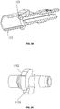
Fig. 5 is a structural schematic diagram of a snap joint of an embodiment of the disclosure. -
Fig. 6 is a whole schematic diagram of an optical fiber connector of an embodiment of the disclosure. -
Fig. 7 is an application schematic diagram of an optical fiber connector of an embodiment of the disclosure. - The disclosure will be further illustrated in detail together with the accompanying drawings and embodiments as follows.
- An embodiment of the disclosure provides an optical fiber connector, as shown in
Fig. 1 and Fig. 2 , which includes: anoptical fiber body 11, a guideprotective sleeve 12, asnap joint 13, a heat-shrinkable bush 14, acoupling nut 15 and asheath 16, wherein
theoptical fiber body 11 is arranged to splice an optical fiber;
the guideprotective sleeve 12 is sleeved on theoptical fiber body 11, and is arranged to guide alignment between theoptical fiber body 11 and an optical fiber adaptor, and protect apin component 112 of theoptical fiber body 11 to prevent thepin component 112 from being damaged;
thesnap joint 13 is arranged on an outer wall of theoptical fiber body 11, and is arranged to fix anoptical cable 17 connected to the optical fiber of theoptical fiber body 11;
the protective heat-shrinkable bush 14 wraps thesnap joint 13, extends to a portion of theoptical cable 17, and is arranged to protect thesnap joint 13 and theoptical cable 17 fixed by thesnap joint 13, playing the role of dustproofing, waterproofing, etc..
thecoupling nut 15 is sleeved on theoptical fiber body 11 connected with the guideprotective sleeve 12, and is arranged to be connected to the optical fiber adaptor; and
the sheath16 is sleeved on another region of the optical fiber connector not wrapped by thecoupling nut 15, and extends to a portion of the protective heat-shrinkable bush 14, playing the role of dustproofing, waterproofing, etc.. - Here, the
optical fiber body 11 may be an SC type optical fiber body, or may be an FC type optical fiber body, or may be a duplex optical fiber body and the like; when theoptical fiber body 11 is the SC type optical fiber body, theoptical fiber body 11 includes: afront sleeve 111, thepin component 112, aspring 113, an 0-shaped ring 114, arear sleeve 115 and anoptical fiber 116; and when theoptical fiber body 11 is other types of optical fiber bodies, the compositions of theoptical fiber body 11 are contents which can be learned from common knowledge by those skilled in the art, and therefore are not repeated anymore. - Specifically, the
snap joint 13 may be arranged on an outer wall of therear sleeve 115 of the optical fiber body, and is arranged to fix theoptical cable 17 connected to theoptical fiber 116 of theoptical fiber body 11. - The
coupling nut 15 may be sleeved on theoptical fiber body 11 through asnap ring 18 arranged on the outer wall of theoptical fiber body 11; specifically, thecoupling nut 15 may be sleeved on theoptical fiber body 11 through thesnap ring 18 arranged on an outer wall of therear sleeve 115 of theoptical fiber body 11; correspondingly, thesheath 16 may also be sleeved on another region of the optical fiber connector not wrapped by thecoupling nut 15 through thesnap ring 18. - The
coupling nut 15 is internally provided with a thread, and is connected with the optical fiber adaptor through the internal thread. - The guide
protective sleeve 12 may be made of a plastic material, such as polyetherimide (PEI), nylon and the like;
thesnap joint 13 may be made of a metal material, such as stainless steel and the like;
the heat-shrinkable bush 14 may be made of a double-arm heat-shrinkable tube, and may specifically be various types of existing double-arm heat-shrinkable tubes;
thecoupling nut 15 may be made of a plastic material, such as PEI, nylon and the like;
thesheath 16 may be a plastic material, such as thermoplastic polyurethane elastomer rubber (TPU) and the like;
thepin component 112 is designed in the guideprotective sleeve 12, and such the design mode not only can protect thepin component 112 to prevent thepin component 112 from being damaged, but also can play a good guiding role when the optical fiber connector and the optical fiber adaptor are in butting insertion. - In a practical application, the
optical cable 17 may be an optical cable with functions such as dustproofing, waterproofing and the like. - In an embodiment, as shown in
Fig. 3A and Fig. 3B , the guideprotective sleeve 12 is connected with therear sleeve 115 of theoptical fiber body 11, an inner wall of the guideprotective sleeve 12 is provided with afirst positioning key 121 and afirst positioning groove 122, the outer wall of therear sleeve 115 is provided with asecond positioning groove 1151 and asecond positioning key 1152 at corresponding positions, the guideprotective sleeve 12 and therear sleeve 115 are combined together firmly by fastening of thefirst positioning key 121 and thesecond positioning groove 1151 and fastening of thefirst positioning groove 122 and thesecond positioning key 1152, and the adopted key-groove and groove-key structure not only can play a positioning role, but also can prevent a rotation between the guideprotective sleeve 12 and therear sleeve 115. - Numbers of the
first positioning key 121, thefirst positioning groove 122, thesecond positioning groove 1151 and thesecond positioning key 1152 can be determined as needed. - Here, in a practical application, as shown in
Fig. 3C , athird positioning key 123 and athird positioning groove 124 may also be arranged on the inner wall of the guideprotective sleeve 12, and by fastening of thethird positioning key 123 and a positioning groove arranged on the optical fiber adaptor, and fastening of thethird positioning groove 124 and a positioning key arranged on the optical fiber adaptor, the guideprotective sleeve 12 and the optical fiber adaptor are combined together firmly. - As shown in
Fig. 4 , abarb 125 may also be arranged on the inner wall of the guideprotective sleeve 12, when therear sleeve 115 is mounted forcibly in the guideprotective sleeve 12, thebarb 125 can firmly fix therear sleeve 115, so that the guideprotective sleeve 12 and therear sleeve 115 can be more firmly combined together. Here, a number of thebarb 125 may be more than one, and the number of thebarb 125 may be determined according to actual requirements. - In a practical application, a number of the snap joint 13 is more than two, and after the waterproof
optical cable 17 is threaded into the guideprotective sleeve 12 and is connected with theoptical fiber 116, more than twosnap joints 13 are used to fasten the waterproofoptical cable 17; in an embodiment, as shown inFig. 5 , the number of the snap joint is two and a positional relation between the twosnap joints 13 is 180 degrees, in other words, the two snap joints fasten the waterproofoptical cable 17 in tandem, thus effectively guaranteeing a certain pulling effect. - In an embodiment, as shown in
Fig. 6 , the optical fiber connector may also include: adustproof cap 19 provided with a thread. When the optical fiber connector in an embodiment of the disclosure is not connected to the optical fiber adaptor, thedustproof cap 19 may be connected to thecoupling nut 15 by the thread to play the role of dustproofing, waterproofing and the like; here, in order to guarantee the sealing property of the optical fiber connector, as shown inFig. 6 , a sealingring 20 may also be added between thedustproof cap 19 and thecoupling nut 15; in addition, thedustproof cap 19 may also be connected to thecoupling nut 15 by a connectingpart 21, thus, thedustproof cap 19 can be prevented from being lost, and moreover, use becomes convenient. In a practical application, as shown inFig. 6 , an end, which is connected with thecoupling nut 15, of the connectingpart 21 may be arranged at the snap ring, and an end, which is connected with thedustproof cap 19, of the connectingpart 21 is arranged at a position adjoining the sealingring 20. - The
dustproof cap 19 may be made of a plastic material, such as PEI, nylon and the like; the sealingring 20 may be made of various silica gel, mastic gum or the like; and the connectingpart 21 may be made of a plastic material, such as nylon and the like. - In a practical application, as shown in
Fig. 7 , an 0-shapedring 71 may be mounted in a groove of a mountingpanel 72, anoptical fiber connector 73 in an embodiment of the disclosure is butted with anoptical fiber adaptor 74 by means of the guiding function of the guide protective sleeve, the coupling nut is fixed on the optical fiber adaptor through the thread, and thereby mounting is complete. - In the optical fiber connector in the embodiment of the disclosure, the guide protective sleeve is sleeved on the optical fiber body, the protective heat-shrinkable bush wraps the optical cable fixed by the snap joint and the snap joint, the coupling nut is sleeved on the optical fiber body connected with the guide protective sleeve, the sheath is sleeved on another region of the optical fiber connector not wrapped by the coupling nut, and thus the optical fiber connector in the embodiment of the disclosure has functions such as waterproofing and dustproofing, and therefore can be applied in changeable environments (for example, aerial environments, etc.) such as outdoor environments.
- In addition, since the guide protective sleeve and the rear sleeve are combined together by adopting the key-groove and groove-key structure, the key-groove and groove-key structure not only can effectively play the positioning role, but also can effectively prevent the rotation between the guide protective sleeve and the rear sleeve.
- When the rear sleeve is forcibly mounted in the guide protective sleeve, the barb arranged on the inner wall of the guide protective sleeve can firmly fix the rear sleeve, and thus the guide protective sleeve and the rear sleeve can be more firmly combined together.
- The snap joints, the positioning relation of which is 180 degrees, fasten the waterproof optical cable, the two snap joints fasten the waterproof optical cable in tandem, thus guaranteeing a certain pulling effect, and thus the waterproof optical cable can be fixed effectively.
- In addition, when the optical fiber connector in the embodiment of the disclosure is not connected with the optical fiber adaptor, the dustproof cap can be connected with the coupling nut through the thread to play the role of dustproofing, waterproofing and the like.
- The sealing ring arranged between the dustproof cap and the coupling nut can effectively guarantee the sealing property of the optical fiber connector.
- Since the dustproof cap is connected with the coupling nut through the connecting part, the dustproof cap can be effectively prevented from being lost, and moreover, use becomes convenient.
- The above are only preferred embodiments of the disclosure and not intended to limit the scope of protection of the disclosure.
Claims (12)
- An optical fiber connector, comprising: a guide protective sleeve, a snap joint, a heat-shrinkable bush, a coupling nut and a sheath, wherein
the guide protective sleeve is sleeved on an optical fiber body of the optical fiber connector, and is arranged to guide alignment between the optical fiber body and an optical fiber adaptor, and protect a pin component of the optical fiber body;
the snap joint is arranged on an outer wall of the optical fiber body, and is arranged to fix an optical cable connected with the optical fiber body;
the protective heat-shrinkable bush wraps the snap joint and extends to a portion of the optical cable;
the coupling nut is sleeved on the optical fiber body connected with the guide protective sleeve, and is arranged to be connected with the optical fiber adaptor; and
the sheath is sleeved on another region of the optical fiber connector not wrapped by the coupling nut, and extends to a portion of the protective heat-shrinkable bush. - The optical fiber connector according to claim 1, wherein the coupling nut is sleeved on the optical fiber body through a snap ring arranged on the outer wall of the optical fiber body; correspondingly, the sheath is sleeved on the another region of the optical fiber connector not wrapped by the coupling nut through the snap ring, and extends to the portion of the protective heat-shrinkable bush.
- The optical fiber connector according to claim 1, wherein the guide protective sleeve is connected with a rear sleeve of the optical fiber body.
- The optical fiber connector according to claim 3, wherein an inner wall of the guide protective sleeve is provided with a first positioning key and a first positioning groove; correspondingly, an outer wall of the rear sleeve is provided with a second positioning groove and a second positioning key at corresponding positions.
- The optical fiber connector according to claim 4, wherein the inner wall of the guide protective sleeve is provided with a barb through which the rear sleeve is fixed.
- The optical fiber connector according to claim 1, wherein the inner wall of the guide protective sleeve is provided with a third positioning key fastened with a positioning groove of the optical fiber connector and a third positioning groove fastened with a positioning key of the optical fiber connector.
- The optical fiber connector according to claim 1, wherein a number of the snap joint is more than one.
- The optical fiber connector according to claim 1, wherein a number of the snap joint is two, and a positional relation between the two snap joints is 180 degrees.
- The optical fiber connector according to claim 1, further comprising: a dustproof cap connected with the coupling nut; wherein the dustproof cap is provided with an external thread.
- The optical fiber connector according to claim 9, further comprising: a sealing ring arranged between the dustproof cap and the coupling nut.
- The optical fiber connector according to claim 9, further comprising: a connecting part connecting the dustproof cap with the coupling nut.
- The optical fiber connector according to claim 1, wherein the coupling nut is internally provided with a thread, and is connected with the optical fiber adaptor by the thread.
Applications Claiming Priority (2)
| Application Number | Priority Date | Filing Date | Title |
|---|---|---|---|
| CN201410413658.5A CN105353472B (en) | 2014-08-20 | 2014-08-20 | a fiber optic connector |
| PCT/CN2015/076462 WO2016026312A1 (en) | 2014-08-20 | 2015-04-13 | Optical fiber connector |
Publications (3)
| Publication Number | Publication Date |
|---|---|
| EP3185058A1 true EP3185058A1 (en) | 2017-06-28 |
| EP3185058A4 EP3185058A4 (en) | 2017-08-30 |
| EP3185058B1 EP3185058B1 (en) | 2022-08-10 |
Family
ID=55329471
Family Applications (1)
| Application Number | Title | Priority Date | Filing Date |
|---|---|---|---|
| EP15833151.2A Active EP3185058B1 (en) | 2014-08-20 | 2015-04-13 | Optical fiber connector |
Country Status (5)
| Country | Link |
|---|---|
| EP (1) | EP3185058B1 (en) |
| CN (1) | CN105353472B (en) |
| ES (1) | ES2928977T3 (en) |
| PT (1) | PT3185058T (en) |
| WO (1) | WO2016026312A1 (en) |
Families Citing this family (6)
| Publication number | Priority date | Publication date | Assignee | Title |
|---|---|---|---|---|
| CN207965231U (en) * | 2017-11-14 | 2018-10-12 | 烽火通信科技股份有限公司 | A kind of fiber connector, fiber connector socket and joint |
| CN110297294B (en) * | 2018-03-23 | 2022-03-22 | 中兴通讯股份有限公司 | A prefabricated optical cable assembly and prefabricated optical cable connector |
| CN110231686B (en) * | 2019-06-21 | 2021-05-18 | 中航光电科技股份有限公司 | Optical fiber connector shell and optical fiber connector |
| CN120352988B (en) * | 2019-10-28 | 2026-04-03 | 华为技术有限公司 | A pre-connector, optical cable assembly and communication device |
| CN114019614B (en) * | 2021-10-22 | 2023-06-09 | 南京华脉科技股份有限公司 | Outdoor optical fiber connector and optical fiber adapter |
| CN115437080B (en) * | 2022-10-08 | 2023-08-18 | 江苏亨通光电股份有限公司 | Optical cable node connecting device |
Family Cites Families (10)
| Publication number | Priority date | Publication date | Assignee | Title |
|---|---|---|---|---|
| US20070025665A1 (en) * | 2005-07-29 | 2007-02-01 | Dean David L Jr | Multi-fiber fiber optic assembly |
| US7744286B2 (en) * | 2007-12-11 | 2010-06-29 | Adc Telecommunications, Inc. | Hardened fiber optic connection system with multiple configurations |
| US7708469B2 (en) * | 2008-04-11 | 2010-05-04 | Corning Cable Systems Llc | Fiber optic connector assembly and method for venting gas inside a fiber optic connector sub-assembly |
| WO2009131993A1 (en) * | 2008-04-21 | 2009-10-29 | Adc Telecommunications, Inc. | Hardened fiber optic connector with connector body joined to cylindrical cable by unitary housing |
| TWM387260U (en) * | 2010-03-31 | 2010-08-21 | Advanced Connectek Inc | Fiber connector |
| CN202372667U (en) * | 2011-12-23 | 2012-08-08 | 孔凡营 | Hot melt optical fiber rapid connector |
| CN102565946B (en) * | 2012-01-06 | 2014-04-16 | 大豪信息技术(威海)有限公司 | Optical hot melt connector and waterproof optical fast connector |
| CN202710787U (en) * | 2012-05-31 | 2013-01-30 | 中航光电科技股份有限公司 | Closed type movable optical fiber connector |
| US8939654B2 (en) * | 2012-09-27 | 2015-01-27 | Adc Telecommunications, Inc. | Ruggedized multi-fiber fiber optic connector with sealed dust cap |
| CN203149152U (en) * | 2013-01-08 | 2013-08-21 | 南京普住光网络有限公司 | On-site assembly type optical fiber connector with special positioning device |
-
2014
- 2014-08-20 CN CN201410413658.5A patent/CN105353472B/en active Active
-
2015
- 2015-04-13 WO PCT/CN2015/076462 patent/WO2016026312A1/en not_active Ceased
- 2015-04-13 ES ES15833151T patent/ES2928977T3/en active Active
- 2015-04-13 PT PT158331512T patent/PT3185058T/en unknown
- 2015-04-13 EP EP15833151.2A patent/EP3185058B1/en active Active
Also Published As
| Publication number | Publication date |
|---|---|
| ES2928977T3 (en) | 2022-11-23 |
| WO2016026312A1 (en) | 2016-02-25 |
| CN105353472B (en) | 2019-12-13 |
| CN105353472A (en) | 2016-02-24 |
| PT3185058T (en) | 2022-10-31 |
| EP3185058A4 (en) | 2017-08-30 |
| EP3185058B1 (en) | 2022-08-10 |
Similar Documents
| Publication | Publication Date | Title |
|---|---|---|
| US10948660B2 (en) | Connecting piece and optical fiber connector | |
| US20250085486A1 (en) | Optical fiber connector and method of assembling the same on site | |
| EP3185058B1 (en) | Optical fiber connector | |
| US10215929B2 (en) | Plug protection cap, optical fiber connector assembly, fiber plug, and network device | |
| US9482825B1 (en) | Ingress protected optical fiber connector having small diameter (mini-IP connector) | |
| US9618718B2 (en) | Universal remote radio unit bird armored fiber optic cable assembly | |
| US7686519B2 (en) | Hardened fiber optic housing and cable assembly | |
| US9158076B2 (en) | On-site hot-melt quick connector for optical fibers | |
| US9846284B2 (en) | Optical fiber connector assembly | |
| US9772455B2 (en) | Universal optical fiber connector | |
| US7281856B2 (en) | Industrial optical fiber connector assembly | |
| CN204009145U (en) | The joints of optical fibre | |
| CN203786340U (en) | Protective caps, ferrule components, fiber optic connectors, pulling components | |
| GB2470584A (en) | Cable end unit | |
| CN204188843U (en) | A kind of SC type pre-terminated connector | |
| CN105182479A (en) | Multi-core inclined end face optical fiber connector | |
| US9448369B1 (en) | Ingress protected optical fiber connector having small diameter (mini-IP connector) | |
| AU2016215668A1 (en) | Universal remote radio unit bird armored fiber optic cable assembly | |
| CN104076446A (en) | Optical fiber connector |
Legal Events
| Date | Code | Title | Description |
|---|---|---|---|
| STAA | Information on the status of an ep patent application or granted ep patent |
Free format text: STATUS: THE INTERNATIONAL PUBLICATION HAS BEEN MADE |
|
| PUAI | Public reference made under article 153(3) epc to a published international application that has entered the european phase |
Free format text: ORIGINAL CODE: 0009012 |
|
| STAA | Information on the status of an ep patent application or granted ep patent |
Free format text: STATUS: REQUEST FOR EXAMINATION WAS MADE |
|
| 17P | Request for examination filed |
Effective date: 20170320 |
|
| AK | Designated contracting states |
Kind code of ref document: A1 Designated state(s): AL AT BE BG CH CY CZ DE DK EE ES FI FR GB GR HR HU IE IS IT LI LT LU LV MC MK MT NL NO PL PT RO RS SE SI SK SM TR |
|
| AX | Request for extension of the european patent |
Extension state: BA ME |
|
| A4 | Supplementary search report drawn up and despatched |
Effective date: 20170801 |
|
| RIC1 | Information provided on ipc code assigned before grant |
Ipc: G02B 6/38 20060101AFI20170726BHEP |
|
| DAV | Request for validation of the european patent (deleted) | ||
| DAX | Request for extension of the european patent (deleted) | ||
| STAA | Information on the status of an ep patent application or granted ep patent |
Free format text: STATUS: EXAMINATION IS IN PROGRESS |
|
| 17Q | First examination report despatched |
Effective date: 20200721 |
|
| GRAP | Despatch of communication of intention to grant a patent |
Free format text: ORIGINAL CODE: EPIDOSNIGR1 |
|
| STAA | Information on the status of an ep patent application or granted ep patent |
Free format text: STATUS: GRANT OF PATENT IS INTENDED |
|
| INTG | Intention to grant announced |
Effective date: 20220429 |
|
| GRAS | Grant fee paid |
Free format text: ORIGINAL CODE: EPIDOSNIGR3 |
|
| GRAA | (expected) grant |
Free format text: ORIGINAL CODE: 0009210 |
|
| STAA | Information on the status of an ep patent application or granted ep patent |
Free format text: STATUS: THE PATENT HAS BEEN GRANTED |
|
| AK | Designated contracting states |
Kind code of ref document: B1 Designated state(s): AL AT BE BG CH CY CZ DE DK EE ES FI FR GB GR HR HU IE IS IT LI LT LU LV MC MK MT NL NO PL PT RO RS SE SI SK SM TR |
|
| REG | Reference to a national code |
Ref country code: AT Ref legal event code: REF Ref document number: 1510973 Country of ref document: AT Kind code of ref document: T Effective date: 20220815 Ref country code: CH Ref legal event code: EP |
|
| REG | Reference to a national code |
Ref country code: IE Ref legal event code: FG4D |
|
| REG | Reference to a national code |
Ref country code: DE Ref legal event code: R096 Ref document number: 602015080297 Country of ref document: DE |
|
| REG | Reference to a national code |
Ref country code: PT Ref legal event code: SC4A Ref document number: 3185058 Country of ref document: PT Date of ref document: 20221031 Kind code of ref document: T Free format text: AVAILABILITY OF NATIONAL TRANSLATION Effective date: 20221024 |
|
| REG | Reference to a national code |
Ref country code: GR Ref legal event code: EP Ref document number: 20220402097 Country of ref document: GR Effective date: 20221109 |
|
| REG | Reference to a national code |
Ref country code: ES Ref legal event code: FG2A Ref document number: 2928977 Country of ref document: ES Kind code of ref document: T3 Effective date: 20221123 |
|
| REG | Reference to a national code |
Ref country code: NL Ref legal event code: MP Effective date: 20220810 |
|
| REG | Reference to a national code |
Ref country code: LT Ref legal event code: MG9D |
|
| PG25 | Lapsed in a contracting state [announced via postgrant information from national office to epo] |
Ref country code: SE Free format text: LAPSE BECAUSE OF FAILURE TO SUBMIT A TRANSLATION OF THE DESCRIPTION OR TO PAY THE FEE WITHIN THE PRESCRIBED TIME-LIMIT Effective date: 20220810 Ref country code: RS Free format text: LAPSE BECAUSE OF FAILURE TO SUBMIT A TRANSLATION OF THE DESCRIPTION OR TO PAY THE FEE WITHIN THE PRESCRIBED TIME-LIMIT Effective date: 20220810 Ref country code: NO Free format text: LAPSE BECAUSE OF FAILURE TO SUBMIT A TRANSLATION OF THE DESCRIPTION OR TO PAY THE FEE WITHIN THE PRESCRIBED TIME-LIMIT Effective date: 20221110 Ref country code: NL Free format text: LAPSE BECAUSE OF FAILURE TO SUBMIT A TRANSLATION OF THE DESCRIPTION OR TO PAY THE FEE WITHIN THE PRESCRIBED TIME-LIMIT Effective date: 20220810 Ref country code: LV Free format text: LAPSE BECAUSE OF FAILURE TO SUBMIT A TRANSLATION OF THE DESCRIPTION OR TO PAY THE FEE WITHIN THE PRESCRIBED TIME-LIMIT Effective date: 20220810 Ref country code: LT Free format text: LAPSE BECAUSE OF FAILURE TO SUBMIT A TRANSLATION OF THE DESCRIPTION OR TO PAY THE FEE WITHIN THE PRESCRIBED TIME-LIMIT Effective date: 20220810 Ref country code: FI Free format text: LAPSE BECAUSE OF FAILURE TO SUBMIT A TRANSLATION OF THE DESCRIPTION OR TO PAY THE FEE WITHIN THE PRESCRIBED TIME-LIMIT Effective date: 20220810 |
|
| REG | Reference to a national code |
Ref country code: AT Ref legal event code: MK05 Ref document number: 1510973 Country of ref document: AT Kind code of ref document: T Effective date: 20220810 |
|
| PG25 | Lapsed in a contracting state [announced via postgrant information from national office to epo] |
Ref country code: PL Free format text: LAPSE BECAUSE OF FAILURE TO SUBMIT A TRANSLATION OF THE DESCRIPTION OR TO PAY THE FEE WITHIN THE PRESCRIBED TIME-LIMIT Effective date: 20220810 Ref country code: IS Free format text: LAPSE BECAUSE OF FAILURE TO SUBMIT A TRANSLATION OF THE DESCRIPTION OR TO PAY THE FEE WITHIN THE PRESCRIBED TIME-LIMIT Effective date: 20221210 Ref country code: HR Free format text: LAPSE BECAUSE OF FAILURE TO SUBMIT A TRANSLATION OF THE DESCRIPTION OR TO PAY THE FEE WITHIN THE PRESCRIBED TIME-LIMIT Effective date: 20220810 |
|
| PG25 | Lapsed in a contracting state [announced via postgrant information from national office to epo] |
Ref country code: SM Free format text: LAPSE BECAUSE OF FAILURE TO SUBMIT A TRANSLATION OF THE DESCRIPTION OR TO PAY THE FEE WITHIN THE PRESCRIBED TIME-LIMIT Effective date: 20220810 Ref country code: RO Free format text: LAPSE BECAUSE OF FAILURE TO SUBMIT A TRANSLATION OF THE DESCRIPTION OR TO PAY THE FEE WITHIN THE PRESCRIBED TIME-LIMIT Effective date: 20220810 Ref country code: DK Free format text: LAPSE BECAUSE OF FAILURE TO SUBMIT A TRANSLATION OF THE DESCRIPTION OR TO PAY THE FEE WITHIN THE PRESCRIBED TIME-LIMIT Effective date: 20220810 Ref country code: CZ Free format text: LAPSE BECAUSE OF FAILURE TO SUBMIT A TRANSLATION OF THE DESCRIPTION OR TO PAY THE FEE WITHIN THE PRESCRIBED TIME-LIMIT Effective date: 20220810 Ref country code: AT Free format text: LAPSE BECAUSE OF FAILURE TO SUBMIT A TRANSLATION OF THE DESCRIPTION OR TO PAY THE FEE WITHIN THE PRESCRIBED TIME-LIMIT Effective date: 20220810 |
|
| REG | Reference to a national code |
Ref country code: DE Ref legal event code: R097 Ref document number: 602015080297 Country of ref document: DE |
|
| PG25 | Lapsed in a contracting state [announced via postgrant information from national office to epo] |
Ref country code: SK Free format text: LAPSE BECAUSE OF FAILURE TO SUBMIT A TRANSLATION OF THE DESCRIPTION OR TO PAY THE FEE WITHIN THE PRESCRIBED TIME-LIMIT Effective date: 20220810 Ref country code: EE Free format text: LAPSE BECAUSE OF FAILURE TO SUBMIT A TRANSLATION OF THE DESCRIPTION OR TO PAY THE FEE WITHIN THE PRESCRIBED TIME-LIMIT Effective date: 20220810 |
|
| PLBE | No opposition filed within time limit |
Free format text: ORIGINAL CODE: 0009261 |
|
| STAA | Information on the status of an ep patent application or granted ep patent |
Free format text: STATUS: NO OPPOSITION FILED WITHIN TIME LIMIT |
|
| PG25 | Lapsed in a contracting state [announced via postgrant information from national office to epo] |
Ref country code: AL Free format text: LAPSE BECAUSE OF FAILURE TO SUBMIT A TRANSLATION OF THE DESCRIPTION OR TO PAY THE FEE WITHIN THE PRESCRIBED TIME-LIMIT Effective date: 20220810 |
|
| 26N | No opposition filed |
Effective date: 20230511 |
|
| PG25 | Lapsed in a contracting state [announced via postgrant information from national office to epo] |
Ref country code: SI Free format text: LAPSE BECAUSE OF FAILURE TO SUBMIT A TRANSLATION OF THE DESCRIPTION OR TO PAY THE FEE WITHIN THE PRESCRIBED TIME-LIMIT Effective date: 20220810 |
|
| REG | Reference to a national code |
Ref country code: CH Ref legal event code: PL |
|
| GBPC | Gb: european patent ceased through non-payment of renewal fee |
Effective date: 20230413 |
|
| PG25 | Lapsed in a contracting state [announced via postgrant information from national office to epo] |
Ref country code: LU Free format text: LAPSE BECAUSE OF NON-PAYMENT OF DUE FEES Effective date: 20230413 |
|
| REG | Reference to a national code |
Ref country code: BE Ref legal event code: MM Effective date: 20230430 |
|
| PG25 | Lapsed in a contracting state [announced via postgrant information from national office to epo] |
Ref country code: MC Free format text: LAPSE BECAUSE OF FAILURE TO SUBMIT A TRANSLATION OF THE DESCRIPTION OR TO PAY THE FEE WITHIN THE PRESCRIBED TIME-LIMIT Effective date: 20220810 |
|
| PG25 | Lapsed in a contracting state [announced via postgrant information from national office to epo] |
Ref country code: GB Free format text: LAPSE BECAUSE OF NON-PAYMENT OF DUE FEES Effective date: 20230413 |
|
| PG25 | Lapsed in a contracting state [announced via postgrant information from national office to epo] |
Ref country code: MC Free format text: LAPSE BECAUSE OF FAILURE TO SUBMIT A TRANSLATION OF THE DESCRIPTION OR TO PAY THE FEE WITHIN THE PRESCRIBED TIME-LIMIT Effective date: 20220810 Ref country code: LI Free format text: LAPSE BECAUSE OF NON-PAYMENT OF DUE FEES Effective date: 20230430 Ref country code: GB Free format text: LAPSE BECAUSE OF NON-PAYMENT OF DUE FEES Effective date: 20230413 Ref country code: FR Free format text: LAPSE BECAUSE OF NON-PAYMENT OF DUE FEES Effective date: 20230430 Ref country code: CH Free format text: LAPSE BECAUSE OF NON-PAYMENT OF DUE FEES Effective date: 20230430 |
|
| REG | Reference to a national code |
Ref country code: IE Ref legal event code: MM4A |
|
| PG25 | Lapsed in a contracting state [announced via postgrant information from national office to epo] |
Ref country code: BE Free format text: LAPSE BECAUSE OF NON-PAYMENT OF DUE FEES Effective date: 20230430 |
|
| PG25 | Lapsed in a contracting state [announced via postgrant information from national office to epo] |
Ref country code: IE Free format text: LAPSE BECAUSE OF NON-PAYMENT OF DUE FEES Effective date: 20230413 |
|
| PG25 | Lapsed in a contracting state [announced via postgrant information from national office to epo] |
Ref country code: IE Free format text: LAPSE BECAUSE OF NON-PAYMENT OF DUE FEES Effective date: 20230413 |
|
| PG25 | Lapsed in a contracting state [announced via postgrant information from national office to epo] |
Ref country code: BG Free format text: LAPSE BECAUSE OF FAILURE TO SUBMIT A TRANSLATION OF THE DESCRIPTION OR TO PAY THE FEE WITHIN THE PRESCRIBED TIME-LIMIT Effective date: 20220810 |
|
| PG25 | Lapsed in a contracting state [announced via postgrant information from national office to epo] |
Ref country code: BG Free format text: LAPSE BECAUSE OF FAILURE TO SUBMIT A TRANSLATION OF THE DESCRIPTION OR TO PAY THE FEE WITHIN THE PRESCRIBED TIME-LIMIT Effective date: 20220810 |
|
| PGFP | Annual fee paid to national office [announced via postgrant information from national office to epo] |
Ref country code: TR Payment date: 20250327 Year of fee payment: 11 |
|
| PGFP | Annual fee paid to national office [announced via postgrant information from national office to epo] |
Ref country code: DE Payment date: 20250305 Year of fee payment: 11 |
|
| PGFP | Annual fee paid to national office [announced via postgrant information from national office to epo] |
Ref country code: ES Payment date: 20250509 Year of fee payment: 11 |
|
| PGFP | Annual fee paid to national office [announced via postgrant information from national office to epo] |
Ref country code: PT Payment date: 20250409 Year of fee payment: 11 |
|
| PG25 | Lapsed in a contracting state [announced via postgrant information from national office to epo] |
Ref country code: CY Free format text: LAPSE BECAUSE OF FAILURE TO SUBMIT A TRANSLATION OF THE DESCRIPTION OR TO PAY THE FEE WITHIN THE PRESCRIBED TIME-LIMIT; INVALID AB INITIO Effective date: 20150413 |
|
| PG25 | Lapsed in a contracting state [announced via postgrant information from national office to epo] |
Ref country code: HU Free format text: LAPSE BECAUSE OF FAILURE TO SUBMIT A TRANSLATION OF THE DESCRIPTION OR TO PAY THE FEE WITHIN THE PRESCRIBED TIME-LIMIT; INVALID AB INITIO Effective date: 20150413 |
|
| PGFP | Annual fee paid to national office [announced via postgrant information from national office to epo] |
Ref country code: IT Payment date: 20260320 Year of fee payment: 12 |
|
| PGFP | Annual fee paid to national office [announced via postgrant information from national office to epo] |
Ref country code: GR Payment date: 20260310 Year of fee payment: 12 |