EP3185034A1 - Signal processing device - Google Patents
Signal processing device Download PDFInfo
- Publication number
- EP3185034A1 EP3185034A1 EP14900243.8A EP14900243A EP3185034A1 EP 3185034 A1 EP3185034 A1 EP 3185034A1 EP 14900243 A EP14900243 A EP 14900243A EP 3185034 A1 EP3185034 A1 EP 3185034A1
- Authority
- EP
- European Patent Office
- Prior art keywords
- signal
- moving target
- component
- prf
- signals
- Prior art date
- Legal status (The legal status is an assumption and is not a legal conclusion. Google has not performed a legal analysis and makes no representation as to the accuracy of the status listed.)
- Granted
Links
Images


Classifications
-
- G—PHYSICS
- G01—MEASURING; TESTING
- G01S—RADIO DIRECTION-FINDING; RADIO NAVIGATION; DETERMINING DISTANCE OR VELOCITY BY USE OF RADIO WAVES; LOCATING OR PRESENCE-DETECTING BY USE OF THE REFLECTION OR RERADIATION OF RADIO WAVES; ANALOGOUS ARRANGEMENTS USING OTHER WAVES
- G01S7/00—Details of systems according to groups G01S13/00, G01S15/00, G01S17/00
- G01S7/02—Details of systems according to groups G01S13/00, G01S15/00, G01S17/00 of systems according to group G01S13/00
- G01S7/28—Details of pulse systems
- G01S7/285—Receivers
- G01S7/292—Extracting wanted echo-signals
-
- G—PHYSICS
- G01—MEASURING; TESTING
- G01S—RADIO DIRECTION-FINDING; RADIO NAVIGATION; DETERMINING DISTANCE OR VELOCITY BY USE OF RADIO WAVES; LOCATING OR PRESENCE-DETECTING BY USE OF THE REFLECTION OR RERADIATION OF RADIO WAVES; ANALOGOUS ARRANGEMENTS USING OTHER WAVES
- G01S13/00—Systems using the reflection or reradiation of radio waves, e.g. radar systems; Analogous systems using reflection or reradiation of waves whose nature or wavelength is irrelevant or unspecified
- G01S13/02—Systems using reflection of radio waves, e.g. primary radar systems; Analogous systems
- G01S13/50—Systems of measurement based on relative movement of target
- G01S13/52—Discriminating between fixed and moving objects or between objects moving at different speeds
- G01S13/522—Discriminating between fixed and moving objects or between objects moving at different speeds using transmissions of interrupted pulse modulated waves
- G01S13/524—Discriminating between fixed and moving objects or between objects moving at different speeds using transmissions of interrupted pulse modulated waves based upon the phase or frequency shift resulting from movement of objects, with reference to the transmitted signals, e.g. coherent MTi
- G01S13/53—Discriminating between fixed and moving objects or between objects moving at different speeds using transmissions of interrupted pulse modulated waves based upon the phase or frequency shift resulting from movement of objects, with reference to the transmitted signals, e.g. coherent MTi performing filtering on a single spectral line and associated with one or more range gates with a phase detector or a frequency mixer to extract the Doppler information, e.g. pulse Doppler radar
-
- G—PHYSICS
- G01—MEASURING; TESTING
- G01S—RADIO DIRECTION-FINDING; RADIO NAVIGATION; DETERMINING DISTANCE OR VELOCITY BY USE OF RADIO WAVES; LOCATING OR PRESENCE-DETECTING BY USE OF THE REFLECTION OR RERADIATION OF RADIO WAVES; ANALOGOUS ARRANGEMENTS USING OTHER WAVES
- G01S13/00—Systems using the reflection or reradiation of radio waves, e.g. radar systems; Analogous systems using reflection or reradiation of waves whose nature or wavelength is irrelevant or unspecified
- G01S13/88—Radar or analogous systems specially adapted for specific applications
- G01S13/89—Radar or analogous systems specially adapted for specific applications for mapping or imaging
- G01S13/90—Radar or analogous systems specially adapted for specific applications for mapping or imaging using synthetic aperture techniques, e.g. synthetic aperture radar [SAR] techniques
- G01S13/9021—SAR image post-processing techniques
- G01S13/9029—SAR image post-processing techniques specially adapted for moving target detection within a single SAR image or within multiple SAR images taken at the same time
Definitions
- the present invention relates to a signal processing device that reconstructs an image of a moving target.
- a multi-channel synthetic aperture radar has been proposed as means for achieving high functionality and high performance of a synthetic aperture radar.
- HRWS High-Resolution Wide-Swath
- Non-Patent Literature 1 listed below can be implemented.
- HRWS means high resolution and a wide observation width which make it possible to assume that signals received via a plurality of channels are a received signal via a signal channel, and to separate azimuth ambiguity.
- MTI Moving Target Indicator
- Non-Patent Literature 2 listed below can be implemented.
- MTI is a process for detecting a moving target by using correspondences between signals received via channels to remove clutter.
- Non-Patent Literatures 3 and 4 Studies to implement both HRWS and MTI are disclosed by Non-Patent Literatures 3 and 4, and show that when implementing HRWS, a combination of reception antennas with a low correlation among channels is desirable, whereas when implementing MTI, a combination of reception antennas with a high correlation among channels is desirable.
- the present invention has been made in order to solve the above-mentioned problem, and it is therefore an object of the present invention to provide a signal processing device that can achieve high resolution and a wide observation width without increasing the number of channels, and that can also detect a moving target.
- a signal processing device comprising: a signal combining means for, when a plurality of reception antennas, the reception antennas being disposed along an orbital direction of a platform in which a radar device is mounted, receive signals which are included in signals repeatedly transmitted from a transmitting antenna and which are reflected by a stationary target or a moving target, combining the received signals of the plurality of reception antennas in such a way that aliasing noise components associated with the stationary target and included in the received signals of the plurality of reception antennas are canceled out, and outputting a composite signal; a moving target component extracting means for suppressing a stationary target component and an aliasing noise component associated with the moving target, the stationary target component and the aliasing noise component being included in the composite signal outputted from the signal combining means, and extracting a moving target component included in the composite signal; and an image reconstructing means for reconstructing an image of the moving target from the moving target component extracted by the moving target component extracting means.
- the signal processing device comprises the moving target component extracting means for suppressing the stationary target component and the aliasing noise component associated with the moving target, the stationary target component and the aliasing noise component being included in the composite signal outputted from the signal combining means, and extracting the moving target component included in the composite signal, and the image reconstructing means reconstructs an image of the moving target from the moving target component extracted by the moving target component extracting means, there is provided an advantage of being able to achieve high resolution and a wide observation width without increasing the number of channels, and to also detect a moving target.
- the two reception antennas are referred to as the reception antenna ch1 and the reception antenna ch2.
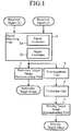
- FIG. 1 is a configuration diagram showing a signal processing device according to Embodiment 1 of the present invention.
- a signal restoring unit 1 when receiving a received signal (1) from the reception antenna ch1, and also receiving a received signal (2) from the reception antenna ch2, a signal restoring unit 1 performs a process of combining the received signals (1) and (2) in such a way that the aliasing components associated with the stationary target and included in the received signals (1) and (2) are canceled out, and outputting a composite signal.
- the signal restoring unit 1 comprises a signal converter 1a to convert the received signals (1) and (2) which are signals in a time domain into signals in a frequency domain, and to output the signals in the frequency domain as Doppler frequency signals (1) and (2), and a signal combiner 1b to cyclically shift the Doppler frequency signals (1) and (2) outputted from the signal converter 1a by one-half of the pulse repetition frequency PRF, to combine the Doppler frequency signals (1) and (2) after the cyclic shift in such a way that the aliasing components associated with the stationary target and included in the Doppler frequency signals (1) and (2) after the cyclic shift are canceled out, and to output a composite signal.
- a signal converter 1a to convert the received signals (1) and (2) which are signals in a time domain into signals in a frequency domain, and to output the signals in the frequency domain as Doppler frequency signals (1) and (2)
- a signal combiner 1b to cyclically shift the Doppler frequency signals (1) and (2) outputted from the signal converter 1a by one-half of the pulse repetition frequency PR
- the signal restoring unit 1 constructs a signal combining means.
- a stationary target image reconstructing unit 2 performs a process of reconstructing an image of the stationary target from a stationary target component included in the composite signal output from the signal restoring unit 1.
- a rearrangement unit 3 rearranges the spectrum of the composite signal in such a way that the stationary target component and the aliasing component associated with the moving target, the stationary target component and the aliasing component being included in the composite signal output from the signal restoring unit 1, and a moving target component included in the composite signal are separate on the frequency domain.
- a formation unit 4 performs a process of suppressing the stationary target component and the aliasing component associated with the moving target, the stationary target component and the aliasing component being included in the composite signal whose spectrum is rearranged by the rearrangement unit 3, and extracting the moving target component included in the composite signal.
- a moving target component extracting means is comprised of the rearrangement unit 3 and the formation unit 4
- a moving target image reconstructing unit 5 performs a process of reconstructing an image of the moving target from the moving target component extracted by the formation unit 4.
- An image reconstructing means is comprised of the stationary target image reconstructing unit 2 and the moving target image reconstructing unit 5.
- the signal restoring unit 1, the stationary target image reconstructing unit 2, the rearrangement unit 3, the formation unit 4 and the moving target image reconstructing unit 5, which are the components of the signal processing device, are comprised of pieces of hardware for exclusive use (e.g., semiconductor integrated circuits each equipped with a CPU, or one chip microcomputers).
- the signal processing device can be comprised of a computer.
- the signal processing device is comprised of a computer
- a program in which processes performed by the signal restoring unit 1, the stationary target image reconstructing unit 2, the rearrangement unit 3, the formation unit 4 and the moving target image reconstructing unit 5 are described can be stored in a memory of the computer, and a CPU of the computer can be made to execute the program stored in the memory.
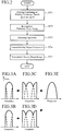
- FIG. 2 is a flow chart showing the details of processing performed by the signal processing device according to Embodiment 1 of the present invention.
- the transmitting antenna and the reception antennas ch1 and ch2 are disposed along the orbital direction of the moving target, and the reception antenna ch1 is disposed at a position a distance ⁇ x 1 away from the transmitting antenna and the reception antenna ch2 is disposed at a position a distance ⁇ x 2 away from the transmitting antenna.
- Pulse signals which are included in the pulse signals emitted at the pulse repetition frequency PRF from the transmitting antenna, and which are reflected by the stationary target are received by the reception antennas ch1 and ch2.
- the propagation distance r i (t) of each pulse signal is expressed by the following Equation (1).
- i 1 and 2.
- r i t r 0 2 + v plf t 2 + r 0 2 + v plf t + ⁇ x i 2
- r 0 denotes the slant range distance which is the distance from the transmitting antenna to the stationary target
- v plf denotes the moving speed of a platform in which a radar device is mounted.
- Equation (1) The propagation distance r i (t) of each pulse signal expressed by the Equation (1) can be simplified to the following Equation (2) when a Taylor approximation is introduced into the Equation (1).
- the Doppler frequency signals S i (f) which are the Doppler frequency components of the received signals (1) and (2) of the reception antennas ch1 and ch2 are expressed as signals in each of which a phase rotation corresponding to a time shift of - ⁇ x i /2v plf and a distance change of ⁇ x i 2 /4r 0 is provided for U(f) which is the Doppler frequency component of each of the received signals at a time when normal mono-static observations are carried out, as shown in the following Equation (3).
- S i f G i f U f
- G i f exp ⁇ j ⁇ f c ⁇ x i 2 2 cr 0 exp j 2 ⁇ ⁇ x i 2 v plf f
- FIG. 3 is an explanatory drawing showing the waveforms of various signals on the frequency domain.
- FIG. 3A shows the Doppler frequency signal S 1 (f) received by the reception antenna ch1
- FIG. 3B shows the Doppler frequency signal S 2 (f) received by the reception antenna ch2.
- a solid line shows a stationary target component and a broken line shows an aliasing component associated with the stationary target.
- the Doppler frequency signals S i (f) are cyclically shifted by PRF/2 in order to perform matching with the center frequency of the composite signal which includes the stationary target component and which is a broadband signal
- the Doppler frequency signals become ones as shown in Figs. 3C and 3D .
- the Doppler frequency signals after the cyclic shift are denoted by S i (f).
- the signal combiner performs the process, as shown in the following Equation (4), of combining the Doppler frequency signal S 1 (f) after the cyclic shift and the Doppler frequency signal S 2 (f) after the cyclic shift, in such a way that the aliasing components associated with the stationary target and included in the Doppler frequency signals S i (f) after the cyclic shift are canceled out.
- a signal component U-hat(f) as shown in FIG. 3E is acquired as the stationary target component. Because in this specification the symbol of " ⁇ " cannot be attached to the top of any character from the restrictions on electronic applications, such a signal component is denoted by U-hat(f).
- the signal component U-hat(f) which is the composite signal is a wide band signal in which the aliasing components are canceled out, and which is equivalent to a signal acquired by carrying out a mono-static observation.
- the present invention focuses attention on the fact that when a moving target is observed, the aliasing component associated with the moving target remains even if the combining process expressed by the above-mentioned Equation (4) is performed.
- Equation (5) the propagation distance r i (t) of each pulse signal is expressed by the following Equation (5).
- i 1 and 2.
- r i t r 0 + v tgt t 2 + v plf 2 + r 0 + v tgt t 2 + v plf t ⁇ ⁇ x i 2
- v tgt denotes the moving speed in a range direction of the moving target.
- the moving target is not moving in an azimuth direction.
- Equation (5) The propagation distance r i (t) of each pulse signal expressed by the Equation (5) can be simplified to the following Equation (6) when a Taylor approximation is introduced into the Equation (5).
- the Doppler frequency signals R i (f) which is the Doppler frequency components of the received signals (1) and (2) of the reception antennas ch1 and ch2 are expressed as signals in each of which a phase rotation corresponding to a time shift of - ⁇ x i /2v plf , a time shift of -r 0 v tgt /v plf 2 and a distance change of ⁇ x i 2 /4r 0 -V tgt ⁇ x i /v plf -v tgt 2 r 0 /v plf 2 is provided for U(f) which is the Doppler frequency component of each of the received signals at a time when normal mono-static observations are carried out, as shown in the following Equation (7).
- G i f exp ⁇ j ⁇ f c ⁇ x i 2 2 cr 0 exp ⁇ j 2 ⁇ ⁇ x i 2 v plf f
- the signal combiner performs the process, as shown in the following Equation (8), of combining the Doppler frequency signal R 1 (f) after the cyclic shift and the Doppler frequency signal R 2 (f) after the cyclic shift, in such a way that the aliasing components associated with the stationary target and included in the Doppler frequency signals R i (f) after the cyclic shift are canceled out.
- Equation (8) a composite signal having a waveform as shown in FIG. 4E is acquired.
- Equation (9) a signal component Z i -hat(f) as shown in the following Equation (9) is acquired.
- Z ⁇ 1 f H 11 f S ⁇ 1 f + H 12 f S ⁇ 2 f
- Z ⁇ 2 f H 21 f S ⁇ 1 f + H 22 f S ⁇ 2 f
- V ⁇ 1 f H 11 f S ⁇ 1 f ⁇ H 12 f S ⁇ 2 f
- V ⁇ 2 f H 21 f S ⁇ 1 f ⁇ H 22 f S ⁇ 2 f
- V i -hat(f) being multiplied by a coefficient of sin ⁇ _ in the Equation (11) that there remains an aliasing component associated with the moving target and corresponding to a coefficient in which the speed of the moving target and the gap between the reception antennas are reflected.
- the signal processing device reconstructs an image in which the moving target component is emphasized, while, in such a way that the aliasing component of the moving target component in a band in which the stationary target component is small in amount is imaged, suppressing the stationary target component outside the band.
- the signal restoring unit 1 acquires the received signals (1) and (2) of the reception antennas ch1 and ch2.
- the signal converter 1a of the signal restoring unit 1 converts the received signals (1) and (2) into signals in the frequency domain, and outputs the signals in the frequency domain as Doppler frequency signals (1) and (2).
- these Doppler frequency signals (1) and (2) are Doppler frequency signals in each of which aliasing occurs, and these Doppler frequency signals are denoted by R i (f) hereafter.
- the received signals (1) and (2) which are signals in the time domain into signals in the frequency domain. For example, by performing a fast Fourier transform process or a discrete Fourier transform process on the received signals (1) and (2), the received signals (1) and (2) can be converted into signals in the frequency domain.
- the signal combiner 1b of the signal restoring unit 1 When receiving the Doppler frequency signals R i (f) from the signal converter 1a, the signal combiner 1b of the signal restoring unit 1 cyclically shifts each of the Doppler frequency signals R i (f) by PRF/2, as shown in Figs. 4C and 4D , in order to perform matching with the center frequency of the composite signal which includes a stationary target component and a moving target component and which is a broadband signal.
- the signal combiner 1b After cyclically shifting each of the Doppler frequency signals R i (f) by PRF/2, the signal combiner 1b combines the Doppler frequency signal R 1 (f) after the cyclic shift and the Doppler frequency signal R 2 (f) after the cyclic shift in such a way that the aliasing components associated with the stationary target and included in the Doppler frequency signals R i (f) after the cyclic shift are canceled out, and outputs a composite signal as shown in FIG. 4E to the stationary target image reconstructing unit 2 and the rearrangement unit 3.
- the signal combiner 1b performs the combining process expressed by the Equation (8), thereby acquiring signal components U-hat(f-PRF/2) and U-hat(f+PRF/2) as the composite signal, and outputs the signal components U-hat(f-PRF/2) and U-hat(f+PRF/2) to the stationary target image reconstructing unit 2 and the rearrangement unit 3 (in step ST1 of FIG. 2 ).
- the stationary target image reconstructing unit 2 converts the signal components U-hat(f-PRF/2) and U-hat(f+PRF/2) into signals in the time domain, and reconstructs an image of the stationary target from the signals in the time domain (in step ST2).
- a method of reconstructing a stationary target image is disclosed by, for example, following Non-Patent Literatures 5 and 6.
- a range Doppler method, a chirp scaling method, an ⁇ -K method, a polar format method, a back projection method, or the like can be used.
- Non Patent Literature 5 Lan G. Cumming and Frank H. Wong, "digital processing of SYNTHETIC APERTURE RADAR", ARTECH HOUSE
- Non Patent Literature 6 Gharles V Jakowatz Jr., Daniel E. Wahl, Palu H. Eichel, Dennis C. Ghiglia and Paul A. Thompson, "SPOTLIGHT-MODE SYNTHETIC APERTURE RADAR: A SIGNAL PROCESSING APPROACH", KLUWER ACADEMIC PUBLISHERS
- the rearrangement unit 3 rearranges the spectra of the signal components U-hat(f-PRF/2) and _U-hat(f+PRF/2) in such a way that the stationary target component and the aliasing component associated with the moving target, the stationary target component and the aliasing component being included in each of the signal components U-hat(f-PRF/2) and U-hat(f+PRF/2), and the moving target component included in each of the signal components U-hat(f-PRF/2) and U-hat(f+PRF/2) are separate on the frequency domain, as shown in FIG. 4F (in step ST3).
- the rearrangement unit 3 rearranges the spectra of the signal components U-hat(f-PRF/2) and U-hat(f+PRF/2), as shown in the following Equation (12), where, in order to add the moving target components coherently, the conversion of the sign is also carried out.
- U ⁇ ⁇ f ⁇ PRF 2 U ⁇ f + PRF 2
- U ⁇ ⁇ f + PRF 2 ⁇ U ⁇ f ⁇ PRF 2 ⁇ PRF 2 ⁇ f ⁇ PRF 2
- the formation unit 4 suppresses the stationary target component and the aliasing component associated with the moving target, the stationary target component and the aliasing component being included in each of the signal components U -hat(f-PRF/2) and U -hat(f+PRF/2) after the spectrum rearrangement, and extracts the moving target component included in each of the signal components U -hat(f-PRF/2) and U -hat(f+PRF/2) after the spectrum rearrangement, as shown in FIG. 4G (in step ST4).
- the formation unit 4 removes frequency components in each of which a stationary target component remains (in the example of FIG. 4F , low-frequency and high-frequency components except frequency components in a center frequency band), from the signal component U -hat(f) having a bandwidth of -PRF ⁇ f ⁇ PRF, thereby extracting the moving target component existing in the center frequency band.
- the aliasing component associated with the moving target remains, in a small amount, in the center frequency band
- the major component in the center frequency band is the moving target component.
- the formation unit 4 performs the spectrum arranging process of removing the frequency components in each of which a stationary target component remains from the signal component U -hat(f) having a bandwidth of -PRF ⁇ f ⁇ PRF.
- the formation unit 4 can average the electric power of the signal component U -hat(f) in a range direction, and whiten the stationary target component by using a weight W-hat(f) which the formation unit acquires by calculating the square root of the averaged result and then calculating the reciprocal of the square root.
- the spectrum arrangement of the signal component U -hat(f) can be carried out by using the matched filter.
- the moving target component can be extracted from the signal component U -hat(f) by taking into consideration the shift amount corresponding to the Doppler shift.
- a filter bank can be configured by combining filters designed for Doppler shifts, and a plurality of signal components each including a moving speed can be output. Further, these methods can be combined.
- the rearrangement unit 3 can arrange the spectra as follows.
- U ⁇ ⁇ f ⁇ 3 PRF 4 ⁇ U ⁇ f ⁇ 3 PRF 4
- U ⁇ ⁇ f ⁇ PRF 4 U ⁇ f + 3 PRF 4
- U ⁇ ⁇ f + PRF 4 ⁇ U ⁇ f ⁇ 3 PRF 4
- U ⁇ ⁇ f + 3 PRF 4 ⁇ U ⁇ f + 3 PRF 4
- the signal to clutter ratio can be improved.
- This process is achieved by making a copy of a signal and performing replacement in the rearrangement unit 3. For example, by making a copy of a signal and performing replacement, as mentioned above, the signal to clutter ratio can be further improved.
- the process of suppressing the stationary target component and the aliasing component associated with the moving target can be performed and the weight ⁇ (f) described previously can be placed once or twice.
- the signal component can be extracted from ⁇ (f) by taking into consideration the shift amount corresponding to the Doppler shift.
- a filter bank can be configured by combining filters designed for Doppler shifts, and a plurality of signal components each including a moving speed can be output.
- the moving target image reconstructing unit 5 converts the moving target component into a signal in the time domain, and reconstructs an image of the moving target from the signal in the time domain (in step ST5).
- the moving target component which is a signal in the frequency domain into a signal in the time domain.
- the moving target component can be converted into a signal in the time domain.
- a range Doppler method a chirp scaling method, an ⁇ -K method, a polar format method, a back projection method, or the like can be used.
- the moving target image reconstructing unit 5 After reconstructing an image of the moving target, the moving target image reconstructing unit 5 detects one or more pixels each having a larger amplitude value (signal strength) than a preset threshold from among the pixels which construct the image of the moving target, and determines the group of the one or more pixels detected as the moving target.
- This threshold can be determined from, for example, the signal strength associated with the moving target and the signal strength associated with the surroundings of the moving target.
- the moving target image reconstructing unit can suppress remaining clutters and azimuth ambiguity.
- the moving target image reconstructing unit cam replace each negative output with 0.
- the moving target image reconstructing unit 5 can apply different colors to the image of the moving target and the image of the stationary target reconstructed by the stationary target image reconstructing unit 2, to adjust the dynamic range, and, after that, superimpose the image of the moving target and the image of the stationary target on each other.
- the process of reconstructing the image of the moving target, which is performed by the moving target image reconstructing unit 5, and the process of reconstructing the image of the stationary target, which is performed by the stationary target image reconstructing unit 2, can be performed in parallel.
- the signal processing device comprises the rearrangement unit 3 to rearrange the spectra of the signal components U-hat(f-PRF/2) and U-hat(f+PRF/2) output from the signal restoring unit 1 in such a way that the stationary target component and the aliasing component associated with the moving target, the stationary target component and the aliasing component being included in each of the signal components U-hat(f-PRF/2) and U-hat(f+PRF/2), and the moving target component included in each of the signal components U-hat(f-PRF/2) and U-hat(f+PRF/2) are separate on the frequency domain, and the formation unit 4 to suppress the stationary target component and the aliasing component associated with the moving target, the stationary target component and the aliasing component being included in each of the signal components U -hat(f-PRF/2) and U -hat(f+PRF/2) after the spectrum rearrangement
- this configuration is only an example, and the stationary target component and the aliasing component associated with the moving target can be suppressed and the moving target component can be extracted without rearranging the spectra.
- the moving target image reconstructing unit 5 performs a range cell migration process and a matched filter process for azimuth compression on the signal components U-hat(f-PRF/2) and U-hat(f+PRF/2) output from the signal restoring unit 1 in such a way that the stationary target component and the moving target component which are included in each of the signal components U-hat(f-PRF/2) and U-hat(f+PRF/2) are suppressed, and the aliasing component of the moving target component is imaged as a desired signal, thereby extracting the moving target component included in each of the signal components U-hat(f-PRF/2) and U-hat(f+PRF/2).
- the moving target image reconstructing unit 5 constructs a moving target component extracting means.
- the signal restoring unit 1 can combine the received signals (1) and (2) of the reception antenna ch1 and ch2, and output a composite signal, as shown in FIG. 5 .
- the signal restoring unit performs the process in the following way.
- reception antennas ch1 and ch2 are disposed along the orbital direction of the moving target, assuming that the received signals (1) of the reception antenna ch1 are received at times t1, t3, t5, and ..., the received signals (2) of the reception antenna ch2 are received at times t2, t4, t6, and ..., as shown in FIG. 5 .
- the signal restoring unit 1 combines the received signals (1) and the received signals (2) in such a way that the received signals (1) and the received signals (2) are arranged alternately on the time domain, as shown in FIG. 5 .
- the signal processing device can be applied to a radar device that emits pulse signals from a plurality of transmitting antennas.
- the signal processing device that acquires the received signals of the two reception antennas ch1 and ch2 disposed along the orbital direction of a moving target and that detects the moving target is shown.
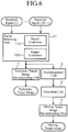
- FIG. 6 is a configuration diagram showing the signal processing device according to Embodiment 2 of the present invention.
- the same reference numerals as those shown in FIG. 1 denote the same components or like components, the explanation of the components will be omitted hereafter.
- a signal restoring unit 11 When receiving the received signals (1) to (2K+1) from the (2K+1) reception antennas disposed along the orbital direction of a moving target, a signal restoring unit 11 performs a process of combining the received signals (1) to (2K+1) in such a way that the aliasing components associated with a stationary target and included in the received signals (1) to (2K+1) are canceled out, and outputting a composite signal.
- the signal restoring unit 11 comprises a signal converter 11a to convert the received signals (1) to (2K+1) which are signals in a time domain into signals in a frequency domain, and to output the signals in the frequency domain as Doppler frequency signals (1) to (2K+1), and a signal combiner 11b to combine the Doppler frequency signals (1) to (2K+1) output from the signal converter 11a in such a way that the aliasing components associated with the stationary target and included in the Doppler frequency signals (1) to (2K+1) are canceled out, and to output a composite signal.
- the signal restoring unit 11 constructs a signal combining means.
- the signal restoring unit 11 acquires the received signals (1) to (2K+1) of the (2K+1) reception antennas.
- the signal converter 11a of the signal restoring unit 11 converts the received signals (1) to (2K+1) into signals in the frequency domain, and outputs the signals in the frequency domain as Doppler frequency signals (1) to (2K+1).
- these Doppler frequency signals (1) to (2K+1) are Doppler frequency signals in each of which aliasing occurs, and these Doppler frequency signals are denoted by R 1 (f) to R 2K+1 (f) hereafter.
- the received signals (1) to (2K+1) which are signals in the time domain into signals in the frequency domain.
- the received signals (1) to (2K+1) can be converted into signals in the frequency domain.
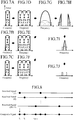
- FIG. 7 is an explanatory drawing showing the waveforms of various signals on the frequency domain.
- FIG. 7A shows the Doppler frequency signal R 1 (f) received by a reception antenna ch1
- FIG. 7B shows the Doppler frequency signal R 2 (f) received by a reception antenna ch2
- FIG. 7C shows the Doppler frequency signal R 3 (f) received by a reception antenna ch3.
- a thick line shows a stationary target component and a thin line shows a moving target component. Further, a thick broken line shows an aliasing component associated with the stationary target, and a thin broken line shows an aliasing component associated with the moving target.
- the signal combiner 11b of the signal restoring unit 11 sets the Doppler frequency signals R 1 (f) to R 2K+1 (f) as R 1 (f) to R 2K+1 (f), without carrying out such a cyclic shift as that carried out by the signal combiner 1b according to the above-mentioned Embodiment 1.
- the signal combiner 11b then performs a process, as shown in the following Equation (13), of combining the Doppler frequency signals R 1 (f) to R 2K+1 (f) in such a way that the aliasing components associated with the stationary target and included in the Doppler frequency signals R 1 (f) to R 2K+1 (f) are canceled out, and outputs a composite signal as shown in FIG. 7G to a stationary target image reconstructing unit 2 and a rearrangement unit 3.
- the signal combiner 11b performs the combining process expressed by the Equation (13) with a bandwidth of -PRF/2 ⁇ f ⁇ PRF/2, thereby acquiring signal components U-hat(f-KPRF) to U-hat(f+KPRF) as the composite signal, and outputs the signal components U-hat(f-KPRF) to U-hat(f+KPRF) to the stationary target image reconstructing unit 2 and the rearrangement unit 3.
- the stationary target image reconstructing unit 2 converts the signal components U-hat(f-KPRF) to U-hat(f+KPRF) into signals in the time domain, and reconstructs an image of the stationary target from the signals in the time domain, like that according to the above-mentioned Embodiment 1.
- a range Doppler method a chirp scaling method, an ⁇ -K method, a polar format method, a back projection method, or the like can be used, like in the case of the above-mentioned Embodiment 1.
- the rearrangement unit 3 rearranges the spectra of the signal components U-hat(f-KPRF) to U-hat(f+KPRF) in such a way that the stationary target component and the aliasing component associated with the moving target, the stationary target component and the aliasing component being included in each of the signal components U-hat(f-KPRF) to U-hat(f+KPRF), and the moving target component included in each of the signal components U-hat(f-KPRF) to U-hat(f+KPRF) are separate on the frequency domain, as shown in FIG. 7I .
- the rearrangement unit 3 rearranges the spectra of the signal components U-hat(f-KPRF) to U-hat(f+KPRF), as shown in the following Equation (14).
- U ⁇ ⁇ f ⁇ PRF 4 U ⁇ f ⁇ k + 1 4 PRF
- U ⁇ ⁇ f + PRF 4 U ⁇ f + k + 1 4 PRF ⁇ PRF 4 ⁇ f ⁇ PRF 4
- the Equation (14) shows that the rearrangement of the spectra causes a transition from the state of FIG. 7G to the state of FIG. 7I .
- the rearrangement of the spectra after the spectra of the signal components U-hat(f-KPRF) to U-hat(f+KPRF) are rearranged first in such a way that the stationary target component and the aliasing component associated with the moving target, the stationary target component and the aliasing component being included in each of the signal components U-hat(f-KPRF) to U-hat(f+KPRF), and the moving target component are separate on the frequency domain, as shown in FIG. 7H , the frequency components in each of which a stationary target component remains can be concentrated in a center frequency band, as shown in FIG. 7I .
- a formation unit 4 suppresses the stationary target component and the aliasing component associated with the moving target, the stationary target component and the aliasing component being included in each of the signal components U -hat(f-KPRF) to U -hat(f+KPRF) after the spectrum rearrangement, and extracts the moving target component included in each of the signal components U -hat(f-KPRF) to U -hat(f+KPRF) after the spectrum rearrangement, as shown in FIG. 7I .
- the formation unit 4 removes frequency components in each of which a stationary target component remains (in the example of FIG. 7I , frequency components in a center frequency band), from the signal component U -hat(f) having a bandwidth of -PRF/2 ⁇ f ⁇ PRF/2, thereby extracting the moving target component existing in a band of frequencies lower than the center frequency band and the moving target component existing in a band of frequencies higher than the center frequency band.
- the aliasing component associated with the moving target remains, in a small amount, in the band of frequencies lower than the center frequency band and in the band of frequencies higher than the center frequency band, the major component in the lower-frequency band and that in the higher-frequency band are the moving target component.
- the formation unit 4 performs the spectrum arranging process of removing the frequency components in each of which a stationary target component remains from the signal component U -hat(f) having a bandwidth of -PRF/2 ⁇ f ⁇ PRF/2.
- the formation unit 4 can average the electric power of the signal component U -hat(f) in a range direction, and whiten the stationary target component by using a weight W-hat(f) which the formation unit acquires by calculating the square root of the averaged result and then calculating the reciprocal of the square root.
- the spectrum arrangement of the signal component U -hat(f) can be carried out by using the matched filter.
- the moving target component can be extracted from the signal component U -hat(f) by taking into consideration the shift amount corresponding to the Doppler shift.
- a filter bank can be configured by combining filters designed for Doppler shifts, and a plurality of signal components each including a moving speed can be output. Further, these methods can be combined.
- the rearrangement unit 3 can arrange the spectra as follows.
- U ⁇ ⁇ f ⁇ K + 1 4 PRF U ⁇ f ⁇ k + 1 4 PRF
- U ⁇ ⁇ f ⁇ PRF 4 U ⁇ f ⁇ k + 1 4 PRF
- U ⁇ ⁇ f + PRF 4 U ⁇ f + k + 1 4 PRF
- U ⁇ ⁇ f + K + 1 4 PRF U ⁇ f + k + 1 4 PRF
- the signal to clutter ratio can be improved.
- This process is achieved by making a copy of a signal and performing replacement in the rearrangement unit 3. For example, by making a copy of a signal and performing replacement, as mentioned above, the signal to clutter ratio can be further improved.
- the process of suppressing the stationary target component and the aliasing component associated with the moving target can be performed and the weight W(f) described previously can be placed once or twice.
- the signal component can be extracted from ⁇ (f) by taking into consideration the shift amount corresponding to the Doppler shift.
- a filter bank can be configured by combining filters designed for Doppler shifts, and a plurality of signal components each including a moving speed can be output.
- a moving target image reconstructing unit 5 converts the moving target component into a signal in the time domain, and reconstructs an image of the moving target from the signal in the time domain, like that according to the above-mentioned Embodiment 1.
- the moving target component which is a signal in the frequency domain into a signal in the time domain.
- the moving target component can be converted into a signal in the time domain.
- a range Doppler method a chirp scaling method, an ⁇ -K method, a polar format method, a back projection method, or the like can be used.
- the moving target image reconstructing unit 5 After reconstructing an image of the moving target, the moving target image reconstructing unit 5 detects one or more pixels each having a larger amplitude value (signal strength) than a preset threshold from among the pixels which construct the image of the moving target, and determines the group of the one or more pixels detected as the moving target, like that according to the above-mentioned Embodiment 1.
- This threshold can be determined from, for example, the signal strength associated with the moving target and the signal strength associated with the surroundings of the moving target.
- the moving target image reconstructing unit can suppress remaining clutters and azimuth ambiguity.
- the moving target image reconstructing unit cam replace each negative output with 0.
- the moving target image reconstructing unit 5 can apply different colors to the image of the moving target and the image of the stationary target reconstructed by the stationary target image reconstructing unit 2, to adjust the dynamic range, and, after that, superimpose the image of the moving target and the image of the stationary target on each other, like that according to the above-mentioned Embodiment 1.
- the process of reconstructing the image of the moving target, which is performed by the moving target image reconstructing unit 5, and the process of reconstructing the image of the stationary target, which is performed by the stationary target image reconstructing unit 2, can be performed in parallel.
- this Embodiment 2 provides an advantage of being able to achieve high resolution and a wide observation width and to also detect a moving target, like the above-mentioned Embodiment 1.
- this configuration is only an example, and the stationary target component and the aliasing component associated with the moving target can be suppressed and the moving target component can be extracted without rearranging the spectra.
- the moving target image reconstructing unit 5 performs a range cell migration process and a matched filter process for azimuth compression on the signal components U-hat(f-KPRF) to U-hat(f+KPRF) output from the signal restoring unit 1 in such a way that the stationary target component and the moving target component which are included in each of the signal components U-hat(f-KPRF) to U-hat(f+KPRF) are suppressed, and the aliasing component of the moving target component is imaged as a desired signal, thereby extracting the moving target component included in each of the signal components U-hat(f-KPRF) to U-hat(f+KPRF). Because the range cell migration process and the matched filter process for azimuth compression are known techniques, a detailed explanation of the processes will be omitted hereafter.
- the signal restoring unit 11 can combine the received signals (1) to (2K+1) of the reception antennas and output a composite signal, as shown in FIG. 8 .
- the signal processing device can be applied to a radar device that emits pulse signals from a plurality of transmitting antennas.
- the signal processing device that acquires the received signals of the two reception antennas ch1 and ch2 disposed along the orbital direction of a moving target and that detects the moving target is shown.
- this Embodiment 3 a signal processing device that acquires the received signals of 2K reception antennas (an even number of reception antennas, the even number being two or more) disposed along the orbital direction of a platform, and that detects a moving target is explained.
- K 1, 2, 3, and ....
- a signal restoring unit 11 acquires the received signals (1) to (2K) of the 2K reception antennas.
- a signal converter 11 a of the signal restoring unit 11 converts the received signals (1) to (2K) into signals in a frequency domain, and outputs the signals in the frequency domain as Doppler frequency signals (1) to (2K).
- these Doppler frequency signals (1) to (2K) are Doppler frequency signals in each of which aliasing occurs, and these Doppler frequency signals are denoted by R 1 (f) to R 2K (f) hereafter.
- the received signals (1) to (2K) which are signals in a time domain into signals in the frequency domain.
- the received signals (1) to (2K) can be converted into signals in the frequency domain.
- a signal combiner 11b of the signal restoring unit 11 sets the Doppler frequency signals R 1 (f) to R 2K (f) as R 1 (f) to R 2K (f), without carrying out such a cyclic shift as that carried out by the signal combiner 1b according to the above-mentioned Embodiment 1.
- the signal combiner 11b then performs a process, as shown in the following Equation (15), of combining the Doppler frequency signals R 1 (f) to R 2K (t) in such a way that the aliasing components associated with the stationary target and included in the Doppler frequency signals R 1 (f) to R 2K (t) are canceled out, and outputs a composite signal as shown in FIG. 4E to a stationary target image reconstructing unit 2 and a rearrangement unit 3.
- Equation (15) the Doppler frequency signals
- the signal combiner 11b performs the combining process expressed by the Equation (15) with a bandwidth of -PRF/2 ⁇ f ⁇ PRF/2, thereby acquiring signal components U-hat(f-(K-1/2)PRF) to U-hat(f+(K-1/2)PRF) as the composite signal, and outputs the signal components U-hat(f-(K-1/2)PRF) to U-hat(f+(K-1/2)PRF) to the stationary target image reconstructing unit 2 and the rearrangement unit 3.
- the stationary target image reconstructing unit 2 converts the signal components U-hat(f-(K-1/2)PRF) to U-hat(f+(K-1/2)PRF) into signals in the time domain, and reconstructs an image of the stationary target from the signals in the time domain, like that according to the above-mentioned Embodiment 1.
- a range Doppler method a chirp scaling method, an ⁇ -K method, a polar format method, a back projection method, or the like can be used, like in the case of the above-mentioned Embodiment 1.
- the rearrangement unit 3 rearranges the spectra of the signal components U-hat(f-(K-1/2)PRF) to U-hat(f+(K-1/2)PRF) in such a way that the stationary target component and the aliasing component associated with the moving target, the stationary target component and the aliasing component being included in each of the signal components U-hat(f-(K-1/2)PRF) to U-hat(f+(K-1/2)PRF), and the moving target component included in each of the signal components U-hat(f-(K-1/2)PRF) to U-hat(f+(K-1/2)PRF) are separate on the frequency domain, as shown in FIG. 4F .
- the rearrangement unit 3 rearranges the spectra of the signal components U-hat(f-(K-1/2)PRF) to U-hat(f+(K-1/2)PRF), as shown in the following Equation (16).
- U ⁇ ⁇ f ⁇ PRF 2 ⁇ U ⁇ f + K ⁇ 1 2 PRF
- U ⁇ ⁇ f + PRF 2 U ⁇ f ⁇ K ⁇ 1 2 PRF ⁇ PRF 2 ⁇ f ⁇ PRF 2
- a formation unit 4 suppresses the stationary target component and the aliasing component associated with the moving target, the stationary target component and the aliasing component being included in each of the signal components U -hat(f-(K-1/2)PRF) to U -hat(f+(K-1/2)PRF) after the spectrum rearrangement, and extracts the moving target component included in each of the signal components U -hat(f-(K-1/2)PRF) to U -hat(f+(K-1/2)PRF) after the spectrum rearrangement, as shown in FIG. 4G .
- the formation unit 4 removes frequency components in each of which a stationary target component remains (in the example of FIG. 4F , low-frequency and high-frequency components except frequency components in a center frequency band), from the signal component U -hat(f) having a bandwidth of -PRF/2 ⁇ f ⁇ PRF/2, thereby extracting the moving target component existing in the center frequency band.
- the aliasing component associated with the moving target remains, in a small amount, in the center frequency band
- the major component in the center frequency band is the moving target component.
- the formation unit 4 performs the spectrum arranging process of removing the frequency components in each of which a stationary target component remains from the signal component U -hat(f) having a bandwidth of -PRF/2 ⁇ f ⁇ PRF/2.
- the formation unit 4 can average the electric power of the signal component U -hat(f) in a range direction, and whiten the stationary target component by using a weight W-hat(f) which the formation unit acquires by calculating the square root of the averaged result and then calculating the reciprocal of the square root.
- the spectrum arrangement of the signal component U -hat(f) can be carried out by using the matched filter.
- the moving target component can be extracted from the signal component U -hat(f) by taking into consideration the shift amount corresponding to the Doppler shift.
- a filter bank can be configured by combining filters designed for Doppler shifts, and a plurality of signal components each including a moving speed can be output. Further, these methods can be combined.
- the rearrangement unit 3 can arrange the spectra as follows.
- U ⁇ ⁇ f ⁇ K ⁇ 1 2 PRF U ⁇ f ⁇ K ⁇ 1 2 PRF
- U ⁇ ⁇ f ⁇ PRF 2 ⁇ U ⁇ f + K ⁇ 1 2 PRF
- U ⁇ ⁇ f + PRF 2 U ⁇ f ⁇ K ⁇ 1 2 PRF
- U ⁇ ⁇ f + K ⁇ 1 2 PRF U ⁇ f + K ⁇ 1 2 PRF
- the signal to clutter ratio can be improved.
- This process is achieved by making a copy of a signal and performing replacement in the rearrangement unit. For example, by making a copy of a signal and performing replacement, as mentioned above, the signal to clutter ratio can be further improved.
- the process of suppressing the stationary target component and the aliasing component associated with the moving target can be performed and the weight ⁇ (f) described previously can be placed once or twice.
- the signal component can be extracted from ⁇ (f) by taking into consideration the shift amount corresponding to the Doppler shift.
- a filter bank can be configured by combining filters designed for Doppler shifts, and a plurality of signal components each including a moving speed can be output.
- a moving target image reconstructing unit 5 converts the moving target component into a signal in the time domain, and reconstructs an image of the moving target from the signal in the time domain, like that according to the above-mentioned Embodiment 1.
- the moving target component which is a signal in the frequency domain into a signal in the time domain.
- the moving target component can be converted into a signal in the time domain.
- a range Doppler method a chirp scaling method, an ⁇ -K method, a polar format method, a back projection method, or the like can be used.
- the moving target image reconstructing unit 5 After reconstructing an image of the moving target, the moving target image reconstructing unit 5 detects one or more pixels each having a larger amplitude value (signal strength) than a preset threshold from among the pixels which construct the image of the moving target, and determines the group of the one or more pixels detected as the moving target, like that according to the above-mentioned Embodiment 1.
- This threshold can be determined from, for example, the signal strength associated with the moving target and the signal strength associated with the surroundings of the moving target.
- the moving target image reconstructing unit can suppress remaining clutters and azimuth ambiguity.
- the moving target image reconstructing unit cam replace each negative output with 0.
- the moving target image reconstructing unit 5 can apply different colors to the image of the moving target and the image of the stationary target reconstructed by the stationary target image reconstructing unit 2, to adjust the dynamic range, and, after that, superimpose the image of the moving target and the image of the stationary target on each other, like that according to the above-mentioned Embodiment 1.
- the process of reconstructing the image of the moving target, which is performed by the moving target image reconstructing unit 5, and the process of reconstructing the image of the stationary target, which is performed by the stationary target image reconstructing unit 2, can be performed in parallel.
- this Embodiment 3 provides an advantage of being able to achieve high resolution and a wide observation width and to also detect a moving target, like the above-mentioned Embodiment 1.
- this configuration is only an example, and the stationary target component and the aliasing component associated with the moving target can be suppressed and the moving target component can be extracted without rearranging the spectra.
- the moving target image reconstructing unit 5 performs a range cell migration process and a matched filter process for azimuth compression on the signal components U-hat(f-(K-1/2)PRF) to U-hat(f+(K-1/2)PRF) output from the signal restoring unit 1 in such a way that the stationary target component and the moving target component which are included in each of the signal components U-hat(f-(K-1/2)PRF) to U-hat(f+(K-1/2)PRF) are suppressed, and the aliasing component of the moving target component is imaged as a desired signal, thereby extracting the moving target component included in each of the signal components U-hat(f-(K-1/2)PRF) to U-hat(f+(K-1/2)PRF). Because the range cell migration process and the matched filter process for azimuth compression are known techniques, a detailed explanation of the processes will be omitted hereafter.
- the signal restoring unit 11 can combine the received signals (1) to (2K) of the reception antennas and output a composite signal, as shown in FIG. 10 .
- the signal processing device can be applied to a radar device that emits pulse signals from a plurality of transmitting antennas.
- the signal processing device is suitable for devices that need to detect a moving target while achieving high resolution and a wide observation width without increasing the number of channels.
Landscapes
- Engineering & Computer Science (AREA)
- Remote Sensing (AREA)
- Radar, Positioning & Navigation (AREA)
- Physics & Mathematics (AREA)
- Computer Networks & Wireless Communication (AREA)
- General Physics & Mathematics (AREA)
- Electromagnetism (AREA)
- Spectroscopy & Molecular Physics (AREA)
- Radar Systems Or Details Thereof (AREA)
Abstract
Description
- The present invention relates to a signal processing device that reconstructs an image of a moving target.
- A multi-channel synthetic aperture radar has been proposed as means for achieving high functionality and high performance of a synthetic aperture radar.
- In the case of a multi-channel synthetic aperture radar, if the number of transmitting antennas is one, it is necessary to use a plurality of reception antennas.
- At this time, by disposing a plurality of reception antennas along the orbital direction of a platform in which a radar device is mounted, HRWS (High-Resolution Wide-Swath) disclosed by Non-Patent Literature 1 listed below can be implemented. HRWS means high resolution and a wide observation width which make it possible to assume that signals received via a plurality of channels are a received signal via a signal channel, and to separate azimuth ambiguity.
- Further, MTI (Moving Target Indicator) disclosed by Non-Patent Literature 2 listed below can be implemented. MTI is a process for detecting a moving target by using correspondences between signals received via channels to remove clutter.
- Studies to implement both HRWS and MTI are disclosed by Non-Patent
Literatures - In order to implement both HRWS and MTI which should satisfy such conflicting requirements about a correlation among channels, it is necessary to increase the number of channels and to select a combination of reception antennas with a low correlation among channels and a combination of reception antennas with a high correlation among channels.
-
- Non Patent Literature 1:
- G. Krieger, N. Gebert and A. Moreira, "Unambiguous SAR signal reconstruction from nonuniform displaced phase center sampling", IEEE Geoscience and Remote Sensing Letters, Vol.1, No.4, pp. 260-264, Oct., 2004.
- Non Patent Literature 2:
- C.E. Livingstone, 1. Sikaneta, C.H. Gierull, S. Chiu, A. Beaudoin, J. Campbell, J Beaudoin, S. Gong and T.A. Knight, "An airborne synthetic aperture radar (SAR) experiment to support RADARSAT-2 ground moving target identification (GMTI)", Can. J. Remote Sensing, Vol.28, No.6, pp. 794-813, 2002.
- Non Patent Literature 3:
- Shuang-Xi Zhang, Meng-Dao Xing, Xiang-Gen Xia, Rui Guo, Yan-Yang Liu and Zheng Bao, "A novel moving target imaging algorithm for HRWS SAE SAR Based on Local Maximum Likelihood Minimum Entropy", IEEE Trans. on Geoscience and Remote Sensing, Vol.52, No.9, pp. 5333-5347, Sept., 2014. (to be published)
- Non Patent Literature 4:
- Yuxiang Shu, Guisheng Liao and Zhiwei Yang, "Design considerations of PRF for optimizing GMTI performance in azimuth multichannel SAR systems with HRWS imaging capability", IEEE Trans. on Geoscience and Remote Sensing, Vol.52, No.4, pp. 2048-2063, April, 2014.
- The problem with conventional signal processing devices configured as set forth above is that although both HRWS and MTI which should satisfy conflicting requirements about a correlation among channels can be implemented if the number of channels is increased, the increase in the number of channels causes increase in the cost, the loadage, the amount of data transmitted, etc. at the time of mounting a conventional signal processing device in a satellite machine or the like.
- The present invention has been made in order to solve the above-mentioned problem, and it is therefore an object of the present invention to provide a signal processing device that can achieve high resolution and a wide observation width without increasing the number of channels, and that can also detect a moving target.
- According to the present invention, there is provided a signal processing device comprising: a signal combining means for, when a plurality of reception antennas, the reception antennas being disposed along an orbital direction of a platform in which a radar device is mounted, receive signals which are included in signals repeatedly transmitted from a transmitting antenna and which are reflected by a stationary target or a moving target, combining the received signals of the plurality of reception antennas in such a way that aliasing noise components associated with the stationary target and included in the received signals of the plurality of reception antennas are canceled out, and outputting a composite signal; a moving target component extracting means for suppressing a stationary target component and an aliasing noise component associated with the moving target, the stationary target component and the aliasing noise component being included in the composite signal outputted from the signal combining means, and extracting a moving target component included in the composite signal; and an image reconstructing means for reconstructing an image of the moving target from the moving target component extracted by the moving target component extracting means.
- Because the signal processing device according to the present invention is configured in such a way that the signal processing device comprises the moving target component extracting means for suppressing the stationary target component and the aliasing noise component associated with the moving target, the stationary target component and the aliasing noise component being included in the composite signal outputted from the signal combining means, and extracting the moving target component included in the composite signal, and the image reconstructing means reconstructs an image of the moving target from the moving target component extracted by the moving target component extracting means, there is provided an advantage of being able to achieve high resolution and a wide observation width without increasing the number of channels, and to also detect a moving target.
-
- FIG. 1
- is a structural diagram showing a signal processing device according to
Embodiment 1 of the present invention; - FIG. 2
- is a flow chart showing the details of processing performed by the signal processing device according to
Embodiment 1 of the present invention; - FIG. 3
- is an explanatory drawing showing the waveforms of various signals on a frequency domain;
- FIG. 4
- is an explanatory drawing showing the waveforms of various signals on the frequency domain;
- FIG. 5
- is an explanatory drawing showing combining of received signals (1) and (2) on a time domain;
- FIG. 6
- is a structural diagram showing a signal processing device according to
Embodiment 2 of the present invention; - FIG. 7
- is an explanatory drawing showing the waveforms of various signals on a frequency domain;
- FIG. 8
- is an explanatory drawing showing combining of received signals (1) to (2K+1) on a time domain;
- FIG. 9
- is a structural diagram showing a signal processing device according to
Embodiment 3 of the present invention; and - FIG. 10
- is an explanatory drawing showing combining of received signals (1) to (2K) on a time domain.
- Hereafter, the preferred embodiments of the present invention will be explained in detail with reference to the drawings.
- In this
Embodiment 1, an example of emitting pulse signals at a pulse repetition frequency PRF from a single transmitting antenna, and, after that, receiving pulse signals each reflected by a stationary target or a moving target by using two reception antennas disposed along the orbital direction of the moving target. - In this
Embodiment 1, because one-half of the limit of the Doppler frequency shift range in which an aliasing component which is an aliasing noise component does not occur as azimuth ambiguity is used as the above-mentioned pulse repetition frequency PRF, azimuth ambiguity occurs as an aliasing component in a Doppler frequency signal component in each of the received signals of the two reception antennas. - Hereafter, the two reception antennas are referred to as the reception antenna ch1 and the reception antenna ch2.
-
FIG. 1 is a configuration diagram showing a signal processing device according toEmbodiment 1 of the present invention. - In the configuration shown in
FIG. 1 , when receiving a received signal (1) from the reception antenna ch1, and also receiving a received signal (2) from the reception antenna ch2, asignal restoring unit 1 performs a process of combining the received signals (1) and (2) in such a way that the aliasing components associated with the stationary target and included in the received signals (1) and (2) are canceled out, and outputting a composite signal. - More specifically, the
signal restoring unit 1 comprises a signal converter 1a to convert the received signals (1) and (2) which are signals in a time domain into signals in a frequency domain, and to output the signals in the frequency domain as Doppler frequency signals (1) and (2), and a signal combiner 1b to cyclically shift the Doppler frequency signals (1) and (2) outputted from the signal converter 1a by one-half of the pulse repetition frequency PRF, to combine the Doppler frequency signals (1) and (2) after the cyclic shift in such a way that the aliasing components associated with the stationary target and included in the Doppler frequency signals (1) and (2) after the cyclic shift are canceled out, and to output a composite signal. - The
signal restoring unit 1 constructs a signal combining means. - A stationary target
image reconstructing unit 2 performs a process of reconstructing an image of the stationary target from a stationary target component included in the composite signal output from thesignal restoring unit 1. - A
rearrangement unit 3 rearranges the spectrum of the composite signal in such a way that the stationary target component and the aliasing component associated with the moving target, the stationary target component and the aliasing component being included in the composite signal output from thesignal restoring unit 1, and a moving target component included in the composite signal are separate on the frequency domain. - A
formation unit 4 performs a process of suppressing the stationary target component and the aliasing component associated with the moving target, the stationary target component and the aliasing component being included in the composite signal whose spectrum is rearranged by therearrangement unit 3, and extracting the moving target component included in the composite signal. - A moving target component extracting means is comprised of the
rearrangement unit 3 and theformation unit 4 - A moving target
image reconstructing unit 5 performs a process of reconstructing an image of the moving target from the moving target component extracted by theformation unit 4. - An image reconstructing means is comprised of the stationary target
image reconstructing unit 2 and the moving targetimage reconstructing unit 5. - In the example shown in
FIG. 1 , it is assumed that thesignal restoring unit 1, the stationary targetimage reconstructing unit 2, therearrangement unit 3, theformation unit 4 and the moving targetimage reconstructing unit 5, which are the components of the signal processing device, are comprised of pieces of hardware for exclusive use (e.g., semiconductor integrated circuits each equipped with a CPU, or one chip microcomputers). As an alternative, the signal processing device can be comprised of a computer. - In the case in which the signal processing device is comprised of a computer, a program in which processes performed by the
signal restoring unit 1, the stationary targetimage reconstructing unit 2, therearrangement unit 3, theformation unit 4 and the moving targetimage reconstructing unit 5 are described can be stored in a memory of the computer, and a CPU of the computer can be made to execute the program stored in the memory. -
FIG. 2 is a flow chart showing the details of processing performed by the signal processing device according toEmbodiment 1 of the present invention. - Next, operations will be explained.
- Before the details of the processing performed by the signal processing device is explained concretely, the formulization of received signals when observing a stationary target and a moving target is explained. First, a case in which only a stationary target is observed, but no moving target is observed is explained.
- Hereafter, it is assumed that the transmitting antenna and the reception antennas ch1 and ch2 are disposed along the orbital direction of the moving target, and the reception antenna ch1 is disposed at a position a distance Δx1 away from the transmitting antenna and the reception antenna ch2 is disposed at a position a distance Δx2 away from the transmitting antenna.
- Pulse signals which are included in the pulse signals emitted at the pulse repetition frequency PRF from the transmitting antenna, and which are reflected by the stationary target are received by the reception antennas ch1 and ch2. The propagation distance ri(t) of each pulse signal is expressed by the following Equation (1). In this equation, i = 1 and 2.

- In the Equation (1), r0 denotes the slant range distance which is the distance from the transmitting antenna to the stationary target, and vplf denotes the moving speed of a platform in which a radar device is mounted.
- The propagation distance ri(t) of each pulse signal expressed by the Equation (1) can be simplified to the following Equation (2) when a Taylor approximation is introduced into the Equation (1).

- Therefore, the Doppler frequency signals Si(f) which are the Doppler frequency components of the received signals (1) and (2) of the reception antennas ch1 and ch2 are expressed as signals in each of which a phase rotation corresponding to a time shift of -Δxi/2vplf and a distance change of Δxi 2/4r0 is provided for U(f) which is the Doppler frequency component of each of the received signals at a time when normal mono-static observations are carried out, as shown in the following Equation (3).

- Because these Doppler frequency signals Si(f) are band-limited by the pulse repetition frequency PRF, the reception antennas ch1 and ch2 actually receive Doppler frequency signals Si(f) in each of which aliasing occurs.
Hereafter, the Doppler frequency signals in each of which aliasing occurs are
denoted by S i(f). -
FIG. 3 is an explanatory drawing showing the waveforms of various signals on the frequency domain. -
FIG. 3A shows the Doppler frequency signal S 1(f) received by the reception antenna ch1, andFIG. 3B shows the Doppler frequency signal S 2(f) received by the reception antenna ch2. InFIG. 3 , a solid line shows a stationary target component and a broken line shows an aliasing component associated with the stationary target. - When the Doppler frequency signals S i(f) are cyclically shifted by PRF/2 in order to perform matching with the center frequency of the composite signal which includes the stationary target component and which is a broadband signal, the Doppler frequency signals become ones as shown in
Figs. 3C and 3D . Hereafter, the Doppler frequency signals after the cyclic shift are denoted by S i(f). - The signal combiner performs the process, as shown in the following Equation (4), of combining the Doppler frequency signal S 1(f) after the cyclic shift and the Doppler frequency signal S 2(f) after the cyclic shift, in such a way that the aliasing components associated with the stationary target and included in the Doppler frequency signals S i(f) after the cyclic shift are canceled out. By performing this combining process, a signal component U-hat(f) as shown in
FIG. 3E is acquired as the stationary target component. Because in this specification the symbol of "^" cannot be attached to the top of any character from the restrictions on electronic applications, such a signal component is denoted by U-hat(f). - The signal component U-hat(f) which is the composite signal is a wide band signal in which the aliasing components are canceled out, and which is equivalent to a signal acquired by carrying out a mono-static observation.

- Next, the formulization of received signals when observing a moving target is explained.
- The present invention focuses attention on the fact that when a moving target is observed, the aliasing component associated with the moving target remains even if the combining process expressed by the above-mentioned Equation (4) is performed.
- First, when pulse signals which are included in the pulse signals emitted at the pulse repetition frequency PRF from the transmitting antenna, and each of which is reflected by a stationary target or a moving target are received by the reception antennas ch1 and ch2, the propagation distance ri(t) of each pulse signal is expressed by the following Equation (5). In this equation, i = 1 and 2.

- In the Equation (5), vtgt denotes the moving speed in a range direction of the moving target. In this
Embodiment 1, it is assumed that the moving target is not moving in an azimuth direction. - The propagation distance ri(t) of each pulse signal expressed by the Equation (5) can be simplified to the following Equation (6) when a Taylor approximation is introduced into the Equation (5).

- Therefore, the Doppler frequency signals Ri(f) which is the Doppler frequency components of the received signals (1) and (2) of the reception antennas ch1 and ch2 are expressed as signals in each of which a phase rotation corresponding to a time shift of -Δxi/2vplf, a time shift of -r0vtgt/vplf 2 and a distance change of Δxi 2/4r0-VtgtΔxi/vplf-vtgt 2r0/vplf 2 is provided for U(f) which is the Doppler frequency component of each of the received signals at a time when normal mono-static observations are carried out, as shown in the following Equation (7).

- Because these Doppler frequency signals Ri(f) are band-limited by the pulse repetition frequency PRF, the reception antennas ch1 and ch2 actually receive Doppler frequency signals Ri(f) in each of which aliasing occurs. Hereafter, the Doppler frequency signals in each of which aliasing occurs are denoted by R i(f).
-
FIG. 4 is an explanatory drawing showing the waveforms of various signals on the frequency domain. -
FIG. 4A shows the Doppler frequency signal R 1(f) received by the reception antenna ch1, andFIG. 4B shows the Doppler frequency signal R 2(f) received by the reception antenna ch2. - In
FIG. 4 , a thick line shows the stationary target component and a thin line shows the moving target component. Further, this figure shows that broken lines make it possible to recognize a situation in which a desired signal and aliasing overlap each other. - When the Doppler frequency signals R i(f) are cyclically shifted by PRF/2 to further broaden the band, in order to perform matching with the center frequency of the composite signal which includes the stationary target component and the moving target component and which is a broadband signal, the Doppler frequency signals become ones as shown in
Figs. 4C and 4D . Hereafter, the Doppler frequency signals after the cyclic shift are denoted by R i(f). - The signal combiner performs the process, as shown in the following Equation (8), of combining the Doppler frequency signal R 1(f) after the cyclic shift and the Doppler frequency signal R 2(f) after the cyclic shift, in such a way that the aliasing components associated with the stationary target and included in the Doppler frequency signals R i(f) after the cyclic shift are canceled out. By performing this combining process, a composite signal having a waveform as shown in
FIG. 4E is acquired.
- By performing the combining process expressed by the Equation (8), the aliasing components are canceled out and a signal component Zi-hat(f) as shown in the following Equation (9) is acquired.

- However, in the combining process expressed by the Equation (8), an aliasing component Vi-hat(f) as shown in the following Equation (10) remains.

- It is seen from division of U-hat(f) shown in the Equation (8) into Zi-hat(f) and Vi-hat(f), an aliasing component remains in accordance with the remaining amount of Vi-hat(f).
- By arranging the combining process expressed by the Equation (8), the combining process can be expressed as shown in the following Equation (11).

- It is seen from Vi-hat(f) being multiplied by a coefficient of sinθ_ in the Equation (11) that there remains an aliasing component associated with the moving target and corresponding to a coefficient in which the speed of the moving target and the gap between the reception antennas are reflected.
- Therefore, the signal processing device according to this
Embodiment 1 reconstructs an image in which the moving target component is emphasized, while, in such a way that the aliasing component of the moving target component in a band in which the stationary target component is small in amount is imaged, suppressing the stationary target component outside the band. - Hereafter, the details of the processing performed by the signal processing device are explained concretely.
- When the reception antennas ch1 and ch2 receive pulse signals which are included in the pulse signals emitted at the pulse repetition frequency PRF from the transmitting antenna and each of which is reflected by a stationary target or a moving target, the
signal restoring unit 1 acquires the received signals (1) and (2) of the reception antennas ch1 and ch2. - When acquiring the received signals (1) and (2) of the reception antennas ch1 and ch2, the signal converter 1a of the
signal restoring unit 1 converts the received signals (1) and (2) into signals in the frequency domain, and outputs the signals in the frequency domain as Doppler frequency signals (1) and (2). - As described above, these Doppler frequency signals (1) and (2) are Doppler frequency signals in each of which aliasing occurs, and these Doppler frequency signals are denoted by R i(f) hereafter. In R i(f), i=1 and 2.
- It doesn't matter how to convert the received signals (1) and (2) which are signals in the time domain into signals in the frequency domain. For example, by performing a fast Fourier transform process or a discrete Fourier transform process on the received signals (1) and (2), the received signals (1) and (2) can be converted into signals in the frequency domain.
- When receiving the Doppler frequency signals R i(f) from the signal converter 1a, the
signal combiner 1b of thesignal restoring unit 1 cyclically shifts each of the Doppler frequency signals R i(f) by PRF/2, as shown inFigs. 4C and 4D , in order to perform matching with the center frequency of the composite signal which includes a stationary target component and a moving target component and which is a broadband signal. - After cyclically shifting each of the Doppler frequency signals R i(f) by PRF/2, the
signal combiner 1b combines the Doppler frequency signal R 1(f) after the cyclic shift and the Doppler frequency signal R 2(f) after the cyclic shift in such a way that the aliasing components associated with the stationary target and included in the Doppler frequency signals R i(f) after the cyclic shift are canceled out, and outputs a composite signal as shown inFIG. 4E to the stationary targetimage reconstructing unit 2 and therearrangement unit 3. - More specifically, the
signal combiner 1b performs the combining process expressed by the Equation (8), thereby acquiring signal components U-hat(f-PRF/2) and U-hat(f+PRF/2) as the composite signal, and outputs the signal components U-hat(f-PRF/2) and U-hat(f+PRF/2) to the stationary targetimage reconstructing unit 2 and the rearrangement unit 3 (in step ST1 ofFIG. 2 ). - When receiving the signal components U-hat(f-PRF/2) and U-hat(f+PRF/2) from the
signal restoring unit 1, the stationary targetimage reconstructing unit 2 converts the signal components U-hat(f-PRF/2) and U-hat(f+PRF/2) into signals in the time domain, and reconstructs an image of the stationary target from the signals in the time domain (in step ST2). - It doesn't matter how to convert the signal components U-hat(f-PRF/2) and U-hat(f+PRF/2) into signals in the time domain. For example, by performing an inverse fast Fourier transform process or an inverse discrete Fourier transform process on the signal components U-hat(f-PRF/2) and U-hat(f+PRF/2), the signal components can be converted into signals in the time domain.
- A method of reconstructing a stationary target image is disclosed by, for example, following
Non-Patent Literatures 5 and 6. For example, a range Doppler method, a chirp scaling method, an ω-K method, a polar format method, a back projection method, or the like can be used. - Non Patent Literature 5: Lan G. Cumming and Frank H. Wong, "digital processing of SYNTHETIC APERTURE RADAR", ARTECH HOUSE
- Non Patent Literature 6: Gharles V Jakowatz Jr., Daniel E. Wahl, Palu H. Eichel, Dennis C. Ghiglia and Paul A. Thompson, "SPOTLIGHT-MODE SYNTHETIC APERTURE RADAR: A SIGNAL PROCESSING APPROACH", KLUWER ACADEMIC PUBLISHERS
- When receiving the signal components U-hat(f-PRF/2) and U-hat(f+PRF/2) from the
signal restoring unit 1, therearrangement unit 3 rearranges the spectra of the signal components U-hat(f-PRF/2) and _U-hat(f+PRF/2) in such a way that the stationary target component and the aliasing component associated with the moving target, the stationary target component and the aliasing component being included in each of the signal components U-hat(f-PRF/2) and U-hat(f+PRF/2), and the moving target component included in each of the signal components U-hat(f-PRF/2) and U-hat(f+PRF/2) are separate on the frequency domain, as shown inFIG. 4F (in step ST3). - More specifically, the
rearrangement unit 3 rearranges the spectra of the signal components U-hat(f-PRF/2) and U-hat(f+PRF/2), as shown in the following Equation (12), where, in order to add the moving target components coherently, the conversion of the sign is also carried out.
- After the
rearrangement unit 3 rearranges the spectra of the signal components U-hat(f-PRF/2) and U-hat(f+PRF/2), theformation unit 4 suppresses the stationary target component and the aliasing component associated with the moving target, the stationary target component and the aliasing component being included in each of the signal components U-hat(f-PRF/2) and U-hat(f+PRF/2) after the spectrum rearrangement, and extracts the moving target component included in each of the signal components U-hat(f-PRF/2) and U-hat(f+PRF/2) after the spectrum rearrangement, as shown inFIG. 4G (in step ST4). - More specifically, the
formation unit 4 removes frequency components in each of which a stationary target component remains (in the example ofFIG. 4F , low-frequency and high-frequency components except frequency components in a center frequency band), from the signal component U-hat(f) having a bandwidth of -PRF≤f<PRF, thereby extracting the moving target component existing in the center frequency band. In the example ofFIG. 4F , while the aliasing component associated with the moving target remains, in a small amount, in the center frequency band, the major component in the center frequency band is the moving target component. - In this embodiment, the
formation unit 4 performs the spectrum arranging process of removing the frequency components in each of which a stationary target component remains from the signal component U-hat(f) having a bandwidth of -PRF≤f<PRF. As an alternative, theformation unit 4 can average the electric power of the signal component U-hat(f) in a range direction, and whiten the stationary target component by using a weight W-hat(f) which the formation unit acquires by calculating the square root of the averaged result and then calculating the reciprocal of the square root. - Further, because by using the weight W-hat(f) twice, a matched filter can be configured, and the power ratio of signal to stationary target can be maximized, the spectrum arrangement of the signal component U-hat(f) can be carried out by using the matched filter.
- Further, when the speed component of the moving target to be observed is predetermined, the moving target component can be extracted from the signal component U-hat(f) by taking into consideration the shift amount corresponding to the Doppler shift.
- Further, a filter bank can be configured by combining filters designed for Doppler shifts, and a plurality of signal components each including a moving speed can be output. Further, these methods can be combined.
- Further, by setting the bandwidth to -PRF/4 ≤ f < PRF/4, the
rearrangement unit 3 can arrange the spectra as follows.
- By thus adding, in the normal restoring process, a moving target component Doppler-shifted toward a range, outside the band, in which the existing amount of clutter is small, the signal to clutter ratio can be improved. This process is achieved by making a copy of a signal and performing replacement in the
rearrangement unit 3. For example, by making a copy of a signal and performing replacement, as mentioned above, the signal to clutter ratio can be further improved. - Also on this signal component, the process of suppressing the stationary target component and the aliasing component associated with the moving target can be performed and the weight Ŵ(f) described previously can be placed once or twice. Further, also in this spectrum arrangement, when the speed component of the moving target to be observed is predetermined, the signal component can be extracted from Û(f) by taking into consideration the shift amount corresponding to the Doppler shift. Further, a filter bank can be configured by combining filters designed for Doppler shifts, and a plurality of signal components each including a moving speed can be output.
- After the
formation unit 4 extracts the moving target component, the moving targetimage reconstructing unit 5 converts the moving target component into a signal in the time domain, and reconstructs an image of the moving target from the signal in the time domain (in step ST5). - It doesn't matter how to convert the moving target component which is a signal in the frequency domain into a signal in the time domain. For example, by performing an inverse fast Fourier transform process or an inverse discrete Fourier transform process on the moving target component, the moving target component can be converted into a signal in the time domain.
- Further, it doesn't matter how to reconstruct a moving target image. For example, a range Doppler method, a chirp scaling method, an ω-K method, a polar format method, a back projection method, or the like can be used.
- After reconstructing an image of the moving target, the moving target
image reconstructing unit 5 detects one or more pixels each having a larger amplitude value (signal strength) than a preset threshold from among the pixels which construct the image of the moving target, and determines the group of the one or more pixels detected as the moving target. - This threshold can be determined from, for example, the signal strength associated with the moving target and the signal strength associated with the surroundings of the moving target.
- Further, by performing a filtering process of detecting an edge or the like on the pixels which construct the moving target image, using an edge detection filter or a filter equivalent to this edge detection filter, the moving target image reconstructing unit can suppress remaining clutters and azimuth ambiguity. At this time, when an edge detection filter is used for the signal amplitude, the moving target image reconstructing unit cam replace each negative output with 0.
- Further, after reconstructing an image of the moving target, the moving target
image reconstructing unit 5 can apply different colors to the image of the moving target and the image of the stationary target reconstructed by the stationary targetimage reconstructing unit 2, to adjust the dynamic range, and, after that, superimpose the image of the moving target and the image of the stationary target on each other. - By thus superimposing the image of the moving target and the image of the stationary target on each other, visual recognition of the images superimposed on each other can be carried out.
- The process of reconstructing the image of the moving target, which is performed by the moving target
image reconstructing unit 5, and the process of reconstructing the image of the stationary target, which is performed by the stationary targetimage reconstructing unit 2, can be performed in parallel. - As can be seen from the above description, because the signal processing device according to Embodiment 1 is configured in such a way that the signal processing device comprises the rearrangement unit 3 to rearrange the spectra of the signal components U-hat(f-PRF/2) and U-hat(f+PRF/2) output from the signal restoring unit 1 in such a way that the stationary target component and the aliasing component associated with the moving target, the stationary target component and the aliasing component being included in each of the signal components U-hat(f-PRF/2) and U-hat(f+PRF/2), and the moving target component included in each of the signal components U-hat(f-PRF/2) and U-hat(f+PRF/2) are separate on the frequency domain, and the formation unit 4 to suppress the stationary target component and the aliasing component associated with the moving target, the stationary target component and the aliasing component being included in each of the signal components U-hat(f-PRF/2) and U-hat(f+PRF/2) after the spectrum rearrangement by the rearrangement unit 3, and to extract the moving target component included in each of the signal components U-hat(f-PRF/2) and U-hat(f+PRF/2) after the spectrum rearrangement, and the moving target image reconstructing unit 5 reconstructs an image of the moving target from the moving target components extracted by the formation unit 4, there is provided an advantage of being able to achieve high resolution and a wide observation width without increasing the number of channels, and to also detect a moving target.
- More specifically, by simply using the two reception antennas ch1 and ch2, an improvement of the resolution, an increase of the observation width, and detection of a moving target can be implemented.
- In this
Embodiment 1, the example in which therearrangement unit 3 rearranges the spectra of the signal components U-hat(f-PRF/2) and U-hat(f+PRF/2) in such a way that the stationary target component and the aliasing component associated with the moving target, and the moving target component are separate on the frequency domain, and theformation unit 4 suppresses the stationary target component and the aliasing component associated with the moving target, the stationary target component and the aliasing component being included in each of the signal components U-hat(f-PRF/2) and U-hat(f+PRF/2) after the spectrum rearrangement, and extracts the moving target component included in each of the signal components U-hat(f-PRF/2) and U-hat(f+PRF/2) after the spectrum rearrangement is shown. - However, this configuration is only an example, and the stationary target component and the aliasing component associated with the moving target can be suppressed and the moving target component can be extracted without rearranging the spectra.
- Concretely, the moving target
image reconstructing unit 5 performs a range cell migration process and a matched filter process for azimuth compression on the signal components U-hat(f-PRF/2) and U-hat(f+PRF/2) output from thesignal restoring unit 1 in such a way that the stationary target component and the moving target component which are included in each of the signal components U-hat(f-PRF/2) and U-hat(f+PRF/2) are suppressed, and the aliasing component of the moving target component is imaged as a desired signal, thereby extracting the moving target component included in each of the signal components U-hat(f-PRF/2) and U-hat(f+PRF/2). - Because the range cell migration process and the matched filter process for azimuth compression are known techniques, a detailed explanation of the processes will be omitted hereafter. In this case, the moving target
image reconstructing unit 5 constructs a moving target component extracting means. - In this
Embodiment 1, the example in which the signal converter 1a of thesignal restoring unit 1 converts the received signals (1) and (2) of the reception antennas ch1 and ch2 into signals in the frequency domain, and thesignal combiner 1b cyclically shifts each of the Doppler frequency signals R i(f) which are the signals in the frequency domain by PRF/2, and, after that, combines the Doppler frequency signals R 1(f) and R 2(f) after the cyclic shift in such a way that the aliasing components associated with the stationary target and included in the Doppler frequency signals R i(f) after the cyclic shift are canceled out, and outputs the signal components U-hat(f-PRF/2) and U-hat(f+PRF/2) which are a composite signal is shown. - However, this configuration is only an example, and, after arranging the received signals (1) and (2) of the reception antennas ch1 and ch2 alternately on the time domain, the
signal restoring unit 1 can combine the received signals (1) and (2) of the reception antenna ch1 and ch2, and output a composite signal, as shown inFIG. 5 . - Concretely, the signal restoring unit performs the process in the following way.
- Because the reception antennas ch1 and ch2 are disposed along the orbital direction of the moving target, assuming that the received signals (1) of the reception antenna ch1 are received at times t1, t3, t5, and ..., the received signals (2) of the reception antenna ch2 are received at times t2, t4, t6, and ..., as shown in
FIG. 5 . - At this time, the
signal restoring unit 1 combines the received signals (1) and the received signals (2) in such a way that the received signals (1) and the received signals (2) are arranged alternately on the time domain, as shown inFIG. 5 . - By thus combining the received signals (1) and (2) of the reception antennas ch1 and ch2 after arranging the received signals (1) and (2) alternately on the time domain, a composite signal in which the aliasing components associated with the stationary target are canceled out, like in the case of combining the Doppler frequency signals R 1(f) and R 2(f) after the cyclic shift, can be acquired.
- Further, although in this
Embodiment 1 the example of applying the signal processing device to a radar device that emits pulse signals from a single transmitting antenna is shown, the signal processing device can be applied to a radar device that emits pulse signals from a plurality of transmitting antennas. - In the above-mentioned
Embodiment 1, the signal processing device that acquires the received signals of the two reception antennas ch1 and ch2 disposed along the orbital direction of a moving target and that detects the moving target is shown. - In contrast with this, in this
Embodiment 2, a signal processing device that acquires the received signals of (2K+1) reception antennas (an odd number of reception antennas, the odd number being three or more) disposed along the orbital direction of a platform, and that detects a moving target is explained. In this embodiment, K=1, 2, 3, and .... - In this
Embodiment 2, because 1/(2K+1)th of the limit of the Doppler frequency shift range in which an aliasing component which is an aliasing noise component does not occur as azimuth ambiguity is used as a pulse repetition frequency PRF, azimuth ambiguity occurs as an aliasing component in a Doppler frequency signal component in each of the received signals of the (2K+1) reception antennas. -
FIG. 6 is a configuration diagram showing the signal processing device according toEmbodiment 2 of the present invention. InFIG. 6 , because the same reference numerals as those shown inFIG. 1 denote the same components or like components, the explanation of the components will be omitted hereafter. - When receiving the received signals (1) to (2K+1) from the (2K+1) reception antennas disposed along the orbital direction of a moving target, a
signal restoring unit 11 performs a process of combining the received signals (1) to (2K+1) in such a way that the aliasing components associated with a stationary target and included in the received signals (1) to (2K+1) are canceled out, and outputting a composite signal. - More specifically, the
signal restoring unit 11 comprises asignal converter 11a to convert the received signals (1) to (2K+1) which are signals in a time domain into signals in a frequency domain, and to output the signals in the frequency domain as Doppler frequency signals (1) to (2K+1), and asignal combiner 11b to combine the Doppler frequency signals (1) to (2K+1) output from thesignal converter 11a in such a way that the aliasing components associated with the stationary target and included in the Doppler frequency signals (1) to (2K+1) are canceled out, and to output a composite signal. - The
signal restoring unit 11 constructs a signal combining means. - Next, operations will be explained.
- When the (2K+1) reception antennas receive pulse signals which are included in pulse signals emitted at the pulse repetition frequency PRF from a transmitting antenna and each of which is reflected by a stationary target or a moving target, the
signal restoring unit 11 acquires the received signals (1) to (2K+1) of the (2K+1) reception antennas. - When acquiring the received signals (1) to (2K+1) of the (2K+1) reception antennas, the
signal converter 11a of thesignal restoring unit 11 converts the received signals (1) to (2K+1) into signals in the frequency domain, and outputs the signals in the frequency domain as Doppler frequency signals (1) to (2K+1). - As described above, these Doppler frequency signals (1) to (2K+1) are Doppler frequency signals in each of which aliasing occurs, and these Doppler frequency signals are denoted by R 1(f) to R 2K+1(f) hereafter.
- It doesn't matter how to convert the received signals (1) to (2K+1) which are signals in the time domain into signals in the frequency domain. For example, by performing a fast Fourier transform process or a discrete Fourier transform process on the received signals (1) to (2K+1), the received signals (1) to (2K+1) can be converted into signals in the frequency domain.
-
FIG. 7 is an explanatory drawing showing the waveforms of various signals on the frequency domain. InFIG. 7 , an example of K=1 is shown. -
FIG. 7A shows the Doppler frequency signal R 1(f) received by a reception antenna ch1,FIG. 7B shows the Doppler frequency signal R 2(f) received by a reception antenna ch2, andFIG. 7C shows the Doppler frequency signal R 3(f) received by a reception antenna ch3. - In
FIG. 7 , a thick line shows a stationary target component and a thin line shows a moving target component. Further, a thick broken line shows an aliasing component associated with the stationary target, and a thin broken line shows an aliasing component associated with the moving target. - When receiving the Doppler frequency signals R 1(f) to R 2K+1(f) from the
signal converter 11a, thesignal combiner 11b of thesignal restoring unit 11 sets the Doppler frequency signals R 1(f) to R 2K+1(f) as R 1(f) to R 2K+1(f), without carrying out such a cyclic shift as that carried out by thesignal combiner 1b according to the above-mentionedEmbodiment 1. - The
signal combiner 11b then performs a process, as shown in the following Equation (13), of combining the Doppler frequency signals R 1(f) to R 2K+1(f) in such a way that the aliasing components associated with the stationary target and included in the Doppler frequency signals R 1(f) to R 2K+1(f) are canceled out, and outputs a composite signal as shown inFIG. 7G to a stationary targetimage reconstructing unit 2 and arearrangement unit 3. - More specifically, the
signal combiner 11b performs the combining process expressed by the Equation (13) with a bandwidth of -PRF/2 ≤ f < PRF/2, thereby acquiring signal components U-hat(f-KPRF) to U-hat(f+KPRF) as the composite signal, and outputs the signal components U-hat(f-KPRF) to U-hat(f+KPRF) to the stationary targetimage reconstructing unit 2 and therearrangement unit 3.
- When receiving the signal components U-hat(f-KPRF) to U-hat(f+KPRF) from the
signal restoring unit 11, the stationary targetimage reconstructing unit 2 converts the signal components U-hat(f-KPRF) to U-hat(f+KPRF) into signals in the time domain, and reconstructs an image of the stationary target from the signals in the time domain, like that according to the above-mentionedEmbodiment 1. - It doesn't matter how to convert the signal components U-hat(f-KPRF) to U-hat(f+KPRF) into signals in the time domain. For example, by performing an inverse fast Fourier transform process or an inverse discrete Fourier transform process on the signal components U-hat(f-KPRF) to U-hat(f+KPRF), the signal components can be converted into signals in the time domain.
- Further, as a method of reconstructing a stationary target image, a range Doppler method, a chirp scaling method, an ω-K method, a polar format method, a back projection method, or the like can be used, like in the case of the above-mentioned
Embodiment 1. - When receiving the signal components U-hat(f-KPRF) to U-hat(f+KPRF) from the
signal restoring unit 11, therearrangement unit 3 rearranges the spectra of the signal components U-hat(f-KPRF) to U-hat(f+KPRF) in such a way that the stationary target component and the aliasing component associated with the moving target, the stationary target component and the aliasing component being included in each of the signal components U-hat(f-KPRF) to U-hat(f+KPRF), and the moving target component included in each of the signal components U-hat(f-KPRF) to U-hat(f+KPRF) are separate on the frequency domain, as shown inFIG. 7I . - More specifically, the
rearrangement unit 3 rearranges the spectra of the signal components U-hat(f-KPRF) to U-hat(f+KPRF), as shown in the following Equation (14).
- The Equation (14) shows that the rearrangement of the spectra causes a transition from the state of
FIG. 7G to the state ofFIG. 7I . In the rearrangement of the spectra, after the spectra of the signal components U-hat(f-KPRF) to U-hat(f+KPRF) are rearranged first in such a way that the stationary target component and the aliasing component associated with the moving target, the stationary target component and the aliasing component being included in each of the signal components U-hat(f-KPRF) to U-hat(f+KPRF), and the moving target component are separate on the frequency domain, as shown inFIG. 7H , the frequency components in each of which a stationary target component remains can be concentrated in a center frequency band, as shown inFIG. 7I . - After the
rearrangement unit 3 rearranges the spectra of the signal components U-hat(f-KPRF) to U-hat(f+KPRF), aformation unit 4 suppresses the stationary target component and the aliasing component associated with the moving target, the stationary target component and the aliasing component being included in each of the signal components U-hat(f-KPRF) to U-hat(f+KPRF) after the spectrum rearrangement, and extracts the moving target component included in each of the signal components U-hat(f-KPRF) to U-hat(f+KPRF) after the spectrum rearrangement, as shown inFIG. 7I . - More specifically, the
formation unit 4 removes frequency components in each of which a stationary target component remains (in the example ofFIG. 7I , frequency components in a center frequency band), from the signal component U-hat(f) having a bandwidth of -PRF/2≤f<PRF/2, thereby extracting the moving target component existing in a band of frequencies lower than the center frequency band and the moving target component existing in a band of frequencies higher than the center frequency band. - In the example of
FIG. 7J , while the aliasing component associated with the moving target remains, in a small amount, in the band of frequencies lower than the center frequency band and in the band of frequencies higher than the center frequency band, the major component in the lower-frequency band and that in the higher-frequency band are the moving target component. - In this embodiment, the
formation unit 4 performs the spectrum arranging process of removing the frequency components in each of which a stationary target component remains from the signal component U-hat(f) having a bandwidth of -PRF/2 ≤ f < PRF/2. As an alternative, theformation unit 4 can average the electric power of the signal component U-hat(f) in a range direction, and whiten the stationary target component by using a weight W-hat(f) which the formation unit acquires by calculating the square root of the averaged result and then calculating the reciprocal of the square root. - Further, because by using the weight W-hat(f) twice, a matched filter can be configured, and the power ratio of signal to stationary target can be maximized, the spectrum arrangement of the signal component U-hat(f) can be carried out by using the matched filter.
- Further, when the speed component of the moving target to be observed is predetermined, the moving target component can be extracted from the signal component U-hat(f) by taking into consideration the shift amount corresponding to the Doppler shift.
- Further, a filter bank can be configured by combining filters designed for Doppler shifts, and a plurality of signal components each including a moving speed can be output. Further, these methods can be combined.
- Further, by setting the bandwidth to -PRF/4≤f<PRF/4, the
rearrangement unit 3 can arrange the spectra as follows.
- It is assumed that zero is provided for any band in which no signal is provided.
- By thus adding, in the normal restoring process, a moving target component Doppler-shifted toward a range, outside the band, in which the existing amount of clutter is small, the signal to clutter ratio can be improved. This process is achieved by making a copy of a signal and performing replacement in the
rearrangement unit 3. For example, by making a copy of a signal and performing replacement, as mentioned above, the signal to clutter ratio can be further improved. - Also on this signal component, the process of suppressing the stationary target component and the aliasing component associated with the moving target can be performed and the weight W(f) described previously can be placed once or twice. Further, also in this spectrum arrangement, when the speed component of the moving target to be observed is predetermined, the signal component can be extracted from Û(f) by taking into consideration the shift amount corresponding to the Doppler shift. Further, a filter bank can be configured by combining filters designed for Doppler shifts, and a plurality of signal components each including a moving speed can be output.
- After the
formation unit 4 extracts the moving target component, a moving targetimage reconstructing unit 5 converts the moving target component into a signal in the time domain, and reconstructs an image of the moving target from the signal in the time domain, like that according to the above-mentionedEmbodiment 1. - It doesn't matter how to convert the moving target component which is a signal in the frequency domain into a signal in the time domain. For example, by performing an inverse fast Fourier transform process or an inverse discrete Fourier transform process on the moving target component, the moving target component can be converted into a signal in the time domain.
- Further, it doesn't matter how to reconstruct a moving target image. For example, a range Doppler method, a chirp scaling method, an ω-K method, a polar format method, a back projection method, or the like can be used.
- After reconstructing an image of the moving target, the moving target
image reconstructing unit 5 detects one or more pixels each having a larger amplitude value (signal strength) than a preset threshold from among the pixels which construct the image of the moving target, and determines the group of the one or more pixels detected as the moving target, like that according to the above-mentionedEmbodiment 1. - This threshold can be determined from, for example, the signal strength associated with the moving target and the signal strength associated with the surroundings of the moving target.
- Further, by performing a filtering process of detecting an edge or the like on the pixels which construct the moving target image, using an edge detection filter or a filter equivalent to this edge detection filter, the moving target image reconstructing unit can suppress remaining clutters and azimuth ambiguity. At this time, when an edge detection filter is used for the signal amplitude, the moving target image reconstructing unit cam replace each negative output with 0.
- Further, after reconstructing an image of the moving target, the moving target
image reconstructing unit 5 can apply different colors to the image of the moving target and the image of the stationary target reconstructed by the stationary targetimage reconstructing unit 2, to adjust the dynamic range, and, after that, superimpose the image of the moving target and the image of the stationary target on each other, like that according to the above-mentionedEmbodiment 1. - By thus superimposing the image of the moving target and the image of the stationary target on each other, visual recognition of the images superimposed on each other can be carried out.
- The process of reconstructing the image of the moving target, which is performed by the moving target
image reconstructing unit 5, and the process of reconstructing the image of the stationary target, which is performed by the stationary targetimage reconstructing unit 2, can be performed in parallel. - As can be seen from the above description, even if the number of reception antennas is odd and is three or more, this
Embodiment 2 provides an advantage of being able to achieve high resolution and a wide observation width and to also detect a moving target, like the above-mentionedEmbodiment 1. - In this
Embodiment 2, the example in which therearrangement unit 3 rearranges the spectra of the signal components U-hat(f-KPRF) to U-hat(f+KPRF) in such a way that the stationary target component and the aliasing component associated with the moving target, and the moving target component are separate on the frequency domain, and theformation unit 4 suppresses the stationary target component and the aliasing component associated with the moving target, the stationary target component and the aliasing component being included in each of the signal components U-hat(f-KPRF) to U-hat(f+KPRF) after the spectrum rearrangement, and extracts the moving target component included in each of the signal components U-hat(f-KPRF) to U-hat(f+KPRF) after the spectrum rearrangement is shown. - However, this configuration is only an example, and the stationary target component and the aliasing component associated with the moving target can be suppressed and the moving target component can be extracted without rearranging the spectra.
- Concretely, the moving target
image reconstructing unit 5 performs a range cell migration process and a matched filter process for azimuth compression on the signal components U-hat(f-KPRF) to U-hat(f+KPRF) output from thesignal restoring unit 1 in such a way that the stationary target component and the moving target component which are included in each of the signal components U-hat(f-KPRF) to U-hat(f+KPRF) are suppressed, and the aliasing component of the moving target component is imaged as a desired signal, thereby extracting the moving target component included in each of the signal components U-hat(f-KPRF) to U-hat(f+KPRF). Because the range cell migration process and the matched filter process for azimuth compression are known techniques, a detailed explanation of the processes will be omitted hereafter. - In this
Embodiment 2, the example in which thesignal converter 11a of thesignal restoring unit 11 converts the received signals (1) to (2K+1) of the (2K+1) reception antennas into signals in the frequency domain, and thesignal combiner 11b combines the Doppler frequency signals R 1(f) to R 2K+1(f) which are the signals in the frequency domain in such a way that the aliasing components associated with the stationary target and included in the Doppler frequency signals R 1(f) to R 2K+1(f) are canceled out, and outputs the signal components U-hat(f-KPRF) to U-hat(f+KPRF) which are a composite signal is shown. - However, this configuration is only an example, and, after arranging the received signals (1) to (2K+1) of the (2K+1) reception antennas in proper order on the time domain, the
signal restoring unit 11 can combine the received signals (1) to (2K+1) of the reception antennas and output a composite signal, as shown inFIG. 8 . - Further, although in this
Embodiment 2 the example of applying the signal processing device to a radar device that emits pulse signals from a single transmitting antenna is shown, the signal processing device can be applied to a radar device that emits pulse signals from a plurality of transmitting antennas. - In the above-mentioned
Embodiment 1, the signal processing device that acquires the received signals of the two reception antennas ch1 and ch2 disposed along the orbital direction of a moving target and that detects the moving target is shown. In contrast with this, in thisEmbodiment 3, a signal processing device that acquires the received signals of 2K reception antennas (an even number of reception antennas, the even number being two or more) disposed along the orbital direction of a platform, and that detects a moving target is explained.
In this embodiment, K = 1, 2, 3, and .... - In this
Embodiment 3, because 1/2Kth of the limit of the Doppler frequency shift range in which an aliasing component which is an aliasing noise component does not occur as azimuth ambiguity is used as a pulse repetition frequency PRF, azimuth ambiguity occurs as an aliasing component in a Doppler frequency signal component in each of the received signals of the 2K reception antennas. - Next, operations will be explained.
- When the 2K reception antennas receive pulse signals which are included in pulse signals emitted at the pulse repetition frequency PRF from a transmitting antenna and each of which is reflected by a stationary target or a moving target, a
signal restoring unit 11 acquires the received signals (1) to (2K) of the 2K reception antennas. - When acquiring the received signals (1) to (2K) of the 2K reception antennas, a
signal converter 11 a of thesignal restoring unit 11 converts the received signals (1) to (2K) into signals in a frequency domain, and outputs the signals in the frequency domain as Doppler frequency signals (1) to (2K). - As described above, these Doppler frequency signals (1) to (2K) are Doppler frequency signals in each of which aliasing occurs, and these Doppler frequency signals are denoted by R 1(f) to R 2K(f) hereafter.
- It doesn't matter how to convert the received signals (1) to (2K) which are signals in a time domain into signals in the frequency domain. For example, by performing a fast Fourier transform process or a discrete Fourier transform process on the received signals (1) to (2K), the received signals (1) to (2K) can be converted into signals in the frequency domain.
- When receiving the Doppler frequency signals R 1(f) to R 2K(f) from the
signal converter 11a, asignal combiner 11b of thesignal restoring unit 11 sets the Doppler frequency signals R 1(f) to R 2K(f) as R 1(f) to R 2K(f), without carrying out such a cyclic shift as that carried out by thesignal combiner 1b according to the above-mentionedEmbodiment 1. - The
signal combiner 11b then performs a process, as shown in the following Equation (15), of combining the Doppler frequency signals R 1(f) to R 2K(t) in such a way that the aliasing components associated with the stationary target and included in the Doppler frequency signals R 1(f) to R 2K(t) are canceled out, and outputs a composite signal as shown inFIG. 4E to a stationary targetimage reconstructing unit 2 and arearrangement unit 3. InFIG. 4 , an example of K=1 is shown. - More specifically, the
signal combiner 11b performs the combining process expressed by the Equation (15) with a bandwidth of -PRF/2 ≤ f < PRF/2, thereby acquiring signal components U-hat(f-(K-1/2)PRF) to U-hat(f+(K-1/2)PRF) as the composite signal, and outputs the signal components U-hat(f-(K-1/2)PRF) to U-hat(f+(K-1/2)PRF) to the stationary targetimage reconstructing unit 2 and therearrangement unit 3.
- When receiving the signal components U-hat(f-(K-1/2)PRF) to U-hat(f+(K-1/2)PRF) from the
signal restoring unit 11, the stationary targetimage reconstructing unit 2 converts the signal components U-hat(f-(K-1/2)PRF) to U-hat(f+(K-1/2)PRF) into signals in the time domain, and reconstructs an image of the stationary target from the signals in the time domain, like that according to the above-mentionedEmbodiment 1. - It doesn't matter how to convert the signal components U-hat(f-(K-1/2)PRF) to U-hat(f+(K-1/2)PRF) into signals in the time domain. For example, by performing an inverse fast Fourier transform process or an inverse discrete Fourier transform process on the signal components U-hat(f-(K-1/2)PRF) to U-hat(f+(K-1/2)PRF), the signal components can be converted into signals in the time domain.
- Further, as a method of reconstructing a stationary target image, a range Doppler method, a chirp scaling method, an ω-K method, a polar format method, a back projection method, or the like can be used, like in the case of the above-mentioned
Embodiment 1. - When receiving the signal components U-hat(f-(K-1/2)PRF) to U-hat(f+(K-1/2)PRF) from the
signal restoring unit 11, therearrangement unit 3 rearranges the spectra of the signal components U-hat(f-(K-1/2)PRF) to U-hat(f+(K-1/2)PRF) in such a way that the stationary target component and the aliasing component associated with the moving target, the stationary target component and the aliasing component being included in each of the signal components U-hat(f-(K-1/2)PRF) to U-hat(f+(K-1/2)PRF), and the moving target component included in each of the signal components U-hat(f-(K-1/2)PRF) to U-hat(f+(K-1/2)PRF) are separate on the frequency domain, as shown inFIG. 4F . - More specifically, the
rearrangement unit 3 rearranges the spectra of the signal components U-hat(f-(K-1/2)PRF) to U-hat(f+(K-1/2)PRF), as shown in the following Equation (16).
- After the
rearrangement unit 3 rearranges the spectra of the signal components U-hat(f-(K-1/2)PRF) to U-hat(f+(K-1/2)PRF), aformation unit 4 suppresses the stationary target component and the aliasing component associated with the moving target, the stationary target component and the aliasing component being included in each of the signal components U-hat(f-(K-1/2)PRF) to U-hat(f+(K-1/2)PRF) after the spectrum rearrangement, and extracts the moving target component included in each of the signal components U-hat(f-(K-1/2)PRF) to U-hat(f+(K-1/2)PRF) after the spectrum rearrangement, as shown inFIG. 4G . - More specifically, the
formation unit 4 removes frequency components in each of which a stationary target component remains (in the example ofFIG. 4F , low-frequency and high-frequency components except frequency components in a center frequency band), from the signal component U-hat(f) having a bandwidth of -PRF/2≤f<PRF/2, thereby extracting the moving target component existing in the center frequency band. In the example ofFIG. 4F , while the aliasing component associated with the moving target remains, in a small amount, in the center frequency band, the major component in the center frequency band is the moving target component. - In this embodiment, the
formation unit 4 performs the spectrum arranging process of removing the frequency components in each of which a stationary target component remains from the signal component U-hat(f) having a bandwidth of -PRF/2 ≤ f < PRF/2. - As an alternative, the
formation unit 4 can average the electric power of the signal component U-hat(f) in a range direction, and whiten the stationary target component by using a weight W-hat(f) which the formation unit acquires by calculating the square root of the averaged result and then calculating the reciprocal of the square root. - Further, because by using the weight W-hat(f) twice, a matched filter can be configured, and the power ratio of signal to stationary target can be maximized, the spectrum arrangement of the signal component U-hat(f) can be carried out by using the matched filter.
- Further, when the speed component of the moving target to be observed is predetermined, the moving target component can be extracted from the signal component U-hat(f) by taking into consideration the shift amount corresponding to the Doppler shift.
- Further, a filter bank can be configured by combining filters designed for Doppler shifts, and a plurality of signal components each including a moving speed can be output. Further, these methods can be combined.
- Further, by setting the bandwidth to -PRF/2≤f<PRF/2, the
rearrangement unit 3 can arrange the spectra as follows.
- It is assumed that zero is provided for any band in which no signal is provided. By thus adding, in the normal restoring process, a moving target component Doppler-shifted toward a range, outside the band, in which the existing amount of clutter is small, the signal to clutter ratio can be improved. This process is achieved by making a copy of a signal and performing replacement in the rearrangement unit. For example, by making a copy of a signal and performing replacement, as mentioned above, the signal to clutter ratio can be further improved.
- Also on this signal component, the process of suppressing the stationary target component and the aliasing component associated with the moving target can be performed and the weight Ŵ(f) described previously can be placed once or twice. Further, also in this spectrum arrangement, when the speed component of the moving target to be observed is predetermined, the signal component can be extracted from Û(f) by taking into consideration the shift amount corresponding to the Doppler shift. Further, a filter bank can be configured by combining filters designed for Doppler shifts, and a plurality of signal components each including a moving speed can be output.
- After the
formation unit 4 extracts the moving target component, a moving targetimage reconstructing unit 5 converts the moving target component into a signal in the time domain, and reconstructs an image of the moving target from the signal in the time domain, like that according to the above-mentionedEmbodiment 1. - It doesn't matter how to convert the moving target component which is a signal in the frequency domain into a signal in the time domain. For example, by performing an inverse fast Fourier transform process or an inverse discrete Fourier transform process on the moving target component, the moving target component can be converted into a signal in the time domain.
- Further, it doesn't matter how to reconstruct a moving target image. For example, a range Doppler method, a chirp scaling method, an ω-K method, a polar format method, a back projection method, or the like can be used.
- After reconstructing an image of the moving target, the moving target
image reconstructing unit 5 detects one or more pixels each having a larger amplitude value (signal strength) than a preset threshold from among the pixels which construct the image of the moving target, and determines the group of the one or more pixels detected as the moving target, like that according to the above-mentionedEmbodiment 1. - This threshold can be determined from, for example, the signal strength associated with the moving target and the signal strength associated with the surroundings of the moving target.
- Further, by performing a filtering process of detecting an edge or the like on the pixels which construct the moving target image, using an edge detection filter or a filter equivalent to this edge detection filter, the moving target image reconstructing unit can suppress remaining clutters and azimuth ambiguity. At this time, when an edge detection filter is used for the signal amplitude, the moving target image reconstructing unit cam replace each negative output with 0.
- Further, after reconstructing an image of the moving target, the moving target
image reconstructing unit 5 can apply different colors to the image of the moving target and the image of the stationary target reconstructed by the stationary targetimage reconstructing unit 2, to adjust the dynamic range, and, after that, superimpose the image of the moving target and the image of the stationary target on each other, like that according to the above-mentionedEmbodiment 1. - By thus superimposing the image of the moving target and the image of the stationary target on each other, visual recognition of the images superimposed on each other can be carried out.
- The process of reconstructing the image of the moving target, which is performed by the moving target
image reconstructing unit 5, and the process of reconstructing the image of the stationary target, which is performed by the stationary targetimage reconstructing unit 2, can be performed in parallel. - As can be seen from the above description, even if the number of reception antennas is even and is two or more, this
Embodiment 3 provides an advantage of being able to achieve high resolution and a wide observation width and to also detect a moving target, like the above-mentionedEmbodiment 1. - In this
Embodiment 2, the example in which therearrangement unit 3 rearranges the spectra of the signal components U-hat(f-(K-1/2)PRF) to U-hat(f+(K-1/2)PRF) in such a way that the stationary target component and the aliasing component associated with the moving target, and the moving target component are separate on the frequency domain, and theformation unit 4 extracts the moving target component included in each of the signal components U-hat(f-(K-1/2)PRF) to U-hat(f+(K-1/2)PRF) after the spectrum rearrangement is shown. - However, this configuration is only an example, and the stationary target component and the aliasing component associated with the moving target can be suppressed and the moving target component can be extracted without rearranging the spectra.
- Concretely, the moving target
image reconstructing unit 5 performs a range cell migration process and a matched filter process for azimuth compression on the signal components U-hat(f-(K-1/2)PRF) to U-hat(f+(K-1/2)PRF) output from thesignal restoring unit 1 in such a way that the stationary target component and the moving target component which are included in each of the signal components U-hat(f-(K-1/2)PRF) to U-hat(f+(K-1/2)PRF) are suppressed, and the aliasing component of the moving target component is imaged as a desired signal, thereby extracting the moving target component included in each of the signal components U-hat(f-(K-1/2)PRF) to U-hat(f+(K-1/2)PRF). Because the range cell migration process and the matched filter process for azimuth compression are known techniques, a detailed explanation of the processes will be omitted hereafter. - In this
Embodiment 3, the example in which thesignal converter 11a of thesignal restoring unit 11 converts the received signals (1) to (2K) of the 2K reception antennas into signals in the frequency domain, and thesignal combiner 11b combines the Doppler frequency signals R 1(f) to R 2K(f) which are the signals in the frequency domain in such a way that the aliasing components associated with the stationary target and included in the Doppler frequency signals R 1(f) to R 2K(f) are canceled out, and outputs the signal components U-hat(f-(K-1/2)PRF) to U-hat(f+(K-1/2)PRF) which are a composite signal is shown. - However, this configuration is only an example, and, after arranging the received signals (1) to (2K) of the 2K reception antennas in proper order on the time domain, the
signal restoring unit 11 can combine the received signals (1) to (2K) of the reception antennas and output a composite signal, as shown inFIG. 10 . - Further, although in this
Embodiment 3 the example of applying the signal processing device to a radar device that emits pulse signals from a single transmitting antenna is shown, the signal processing device can be applied to a radar device that emits pulse signals from a plurality of transmitting antennas. - While the invention has been described in its preferred embodiments, it is to be understood that an arbitrary combination of two or more of the above-mentioned embodiments can be made, various changes can be made in an arbitrary component in accordance with any one of the above-mentioned embodiments, and an arbitrary component in accordance with any one of the above-mentioned embodiments can be omitted within the scope of the invention.
- The signal processing device according to the present invention is suitable for devices that need to detect a moving target while achieving high resolution and a wide observation width without increasing the number of channels.
-
- 1
- signal restoring unit (signal synthesis means)
- 1a
- signal converter
- 1b
- signal combiner
- 2
- stationary target image reconstructing unit (image reconstructing means)
- 3
- rearrangement unit (moving target component extracting means)
- 4
- formation unit (moving target component extracting means)
- 5
- moving target image reconstructing unit
- 11
- signal restoring unit (signal combining means)
- 11a
- signal converter
- 11b
- signal combiner.
Claims (11)
- A signal processing device comprising:- a signal combining means for, when a plurality of reception antennas, the reception antennas being disposed along an orbital direction of a platform in which a radar device is mounted, receive signals which are included in signals repeatedly transmitted from a transmitting antenna and which are reflected by a stationary target or a moving target, combining the received signals of the plurality of reception antennas in such a way that aliasing noise components associated with the stationary target and included in the received signals of the plurality of reception antennas are canceled out, and outputting a composite signal;- a moving target component extracting means for suppressing a stationary target component and an aliasing noise component associated with the moving target, the stationary target component and the aliasing noise component being included in the composite signal output from the signal combining means, and extracting a moving target component included in the composite signal; and- an image reconstructing means for reconstructing an image of the moving target from the moving target component extracted by the moving target component extracting means.
- The signal processing device according to claim 1,
wherein the signal combining means converts the received signals of the plurality of reception antennas into signals in a frequency domain, combines the plurality of signals in the frequency domain in such a way that aliasing noise components associated with the stationary target and included in the plurality of signals in the frequency domain are canceled out, and outputs the composite signal. - The signal processing device according to claim 2,
wherein the signal combining means cyclically shifts the plurality of signals in the frequency domain by one-half of a pulse repetition frequency of the signals transmitted from the transmitting antenna, combines the plurality of signals in the frequency domain after the cyclic shift in such a way that the aliasing noise components associated with the stationary target and included in the plurality of signals in the frequency domain after the cyclic shift are canceled out, and outputs the composite signal. - The signal processing device according to claim 1,
wherein the signal combining means arranges the received signals of the plurality of reception antennas alternately on a time domain, and, thereafter, combines the received signals of the plurality of reception antennas and outputs the composite signal. - The signal processing device according to claim 2,
wherein the moving target component extracting means comprises: a rearrangement unit for rearranging a spectrum of the composite signal in such a way that the stationary target component and the aliasing noise component associated with the moving target, the stationary target component and the aliasing noise component being included in the composite signal output from the signal combining means, and the moving target component included in the composite signal are separate on the frequency domain; and a formation unit for suppressing the stationary target component and the aliasing noise component associated with the moving target, the stationary target component and the aliasing noise component being included in the composite signal whose spectrum is rearranged by the rearrangement unit, and extracting the moving target component included in the composite signal. - The signal processing device according to claim 5,
wherein when rearranging the spectrum of the composite signal, the rearrangement unit makes a copy of a signal which is a part included in the composite signal and performs replacement. - The signal processing device according to claim 2,
wherein the moving target component extracting means performs a range cell migration process and a matched filter process for azimuth compression on the composite signal in such a way that the stationary target component and the aliasing noise component associated with the moving target are suppressed, the stationary target component and the aliasing noise component being included in the composite signal output from the signal combining means, thereby extracting the moving target component included in the composite signal. - The signal processing device according to claim 1,
wherein the image reconstructing means detects pixels having a larger amplitude value than a preset threshold from among pixels which construct the image of the moving target, thereby detecting the moving target. - The signal processing device according to claim 1,
wherein the image reconstructing means performs a filtering process of detecting an edge on pixels which construct the image of the moving target. - The signal processing device according to claim 1,
wherein the image reconstructing means reconstructs an image of the stationary target from the stationary target component included in the composite signal output from the signal combining means. - The signal processing device according to claim 10,
wherein the image reconstructing means applies different colors to the image of the moving target and the image of the stationary target, and, thereafter, superimposes the image of the moving target and the image of the stationary target on each other.
Applications Claiming Priority (1)
| Application Number | Priority Date | Filing Date | Title |
|---|---|---|---|
| PCT/JP2014/071759 WO2016027326A1 (en) | 2014-08-20 | 2014-08-20 | Signal processing device |
Publications (3)
| Publication Number | Publication Date |
|---|---|
| EP3185034A1 true EP3185034A1 (en) | 2017-06-28 |
| EP3185034A4 EP3185034A4 (en) | 2018-03-14 |
| EP3185034B1 EP3185034B1 (en) | 2021-09-22 |
Family
ID=55350305
Family Applications (1)
| Application Number | Title | Priority Date | Filing Date |
|---|---|---|---|
| EP14900243.8A Active EP3185034B1 (en) | 2014-08-20 | 2014-08-20 | Signal processing device |
Country Status (5)
| Country | Link |
|---|---|
| US (1) | US10754006B2 (en) |
| EP (1) | EP3185034B1 (en) |
| JP (1) | JP6275265B2 (en) |
| CA (1) | CA2958525C (en) |
| WO (1) | WO2016027326A1 (en) |
Families Citing this family (2)
| Publication number | Priority date | Publication date | Assignee | Title |
|---|---|---|---|---|
| US12174289B2 (en) * | 2018-06-28 | 2024-12-24 | Richwave Technology Corp. | Doppler signal processing device and method thereof for interference suppression |
| IT202000017329A1 (en) * | 2020-07-16 | 2022-01-16 | Ids Georadar S R L | METHOD AND APPARATUS FOR REDUCING BLURRING PHENOMENA IN IMAGES OBTAINED BY GROUND-BASED RADAR |
Family Cites Families (9)
| Publication number | Priority date | Publication date | Assignee | Title |
|---|---|---|---|---|
| GB1481414A (en) * | 1973-08-21 | 1977-07-27 | Emi Ltd | Radar apparatus |
| US4137533A (en) * | 1977-10-12 | 1979-01-30 | United Technologies Corporation | Angle/vector processed, phase-accumulated single vector rotation, variable order adaptive MTI processor |
| US5818383A (en) * | 1981-11-27 | 1998-10-06 | Northrop Grumman Corporation | Interferometric moving vehicle imaging apparatus and method |
| US4628318A (en) * | 1983-12-02 | 1986-12-09 | Rockwell International Corporation | Ground clutter suppression technique |
| JP5106323B2 (en) * | 2008-09-04 | 2012-12-26 | 三菱電機株式会社 | Radar image playback device |
| JP5171517B2 (en) * | 2008-09-30 | 2013-03-27 | 三菱電機株式会社 | Image radar device |
| JP5933295B2 (en) * | 2012-03-05 | 2016-06-08 | 三菱電機株式会社 | Synthetic aperture radar apparatus and moving target detection method thereof |
| DE102012021010B4 (en) | 2012-10-26 | 2022-02-03 | Airbus Defence and Space GmbH | Synthetic aperture radar for simultaneous image acquisition and moving target detection |
| JP2014119344A (en) * | 2012-12-17 | 2014-06-30 | Mitsubishi Electric Corp | Synthetic aperture radar equipment |
-
2014
- 2014-08-20 CA CA2958525A patent/CA2958525C/en active Active
- 2014-08-20 WO PCT/JP2014/071759 patent/WO2016027326A1/en not_active Ceased
- 2014-08-20 JP JP2016543528A patent/JP6275265B2/en active Active
- 2014-08-20 EP EP14900243.8A patent/EP3185034B1/en active Active
- 2014-08-20 US US15/504,853 patent/US10754006B2/en not_active Expired - Fee Related
Also Published As
| Publication number | Publication date |
|---|---|
| JPWO2016027326A1 (en) | 2017-04-27 |
| EP3185034B1 (en) | 2021-09-22 |
| JP6275265B2 (en) | 2018-02-07 |
| CA2958525A1 (en) | 2016-02-25 |
| US10754006B2 (en) | 2020-08-25 |
| WO2016027326A1 (en) | 2016-02-25 |
| EP3185034A4 (en) | 2018-03-14 |
| CA2958525C (en) | 2018-10-30 |
| US20170269193A1 (en) | 2017-09-21 |
Similar Documents
| Publication | Publication Date | Title |
|---|---|---|
| EP2677343B1 (en) | Passive radar device | |
| Babur et al. | Nearly orthogonal waveforms for MIMO FMCW radar | |
| EP3214460B1 (en) | Synthetic aperture radar device | |
| EP2873987A1 (en) | Radar system and data processing device | |
| US10228459B2 (en) | Radar system and radar signal processing device | |
| Cooper et al. | Using FMCW Doppler radar to detect targets up to the maximum unambiguous range | |
| JP5606097B2 (en) | Passive radar device | |
| EP2684072A1 (en) | Sar data processing | |
| EP3273265A1 (en) | Radar moving image creation device and method | |
| US20240288538A1 (en) | Radar device | |
| Neemat et al. | Decoupling the Doppler ambiguity interval from the maximum operational range and range-resolution in FMCW radars | |
| JP6218476B2 (en) | Radar equipment | |
| EP3724680B1 (en) | System and method for synthetic aperture radar image formation | |
| Olivadese et al. | Passive ISAR imaging of ships by using DVB-T signals | |
| EP3185034B1 (en) | Signal processing device | |
| CN119667675A (en) | Spaceborne bistatic SAR imaging system and method | |
| JP6629279B2 (en) | Radar apparatus and radar signal processing method thereof | |
| Gao et al. | Improved spectrum reconstruction technique based on chirp rate modulation in stepped-frequency SAR | |
| JP2014052336A (en) | Signal processing apparatus and radar observation method | |
| CN114236491A (en) | A method and system for simultaneous imaging and detection based on coding array | |
| US20250076454A1 (en) | Radar apparatus, radar signal generation circuitry, and transmission method | |
| Zhang et al. | MIMO-SAR solution based on azimuth phase coding waveforms and digital beamforming | |
| Han et al. | Diversity schemes analysis for MIMO synthetic aperture radar | |
| Wang | OFDM waveform diversity design for MIMO SAR imaging | |
| Zhou et al. | An innovative spaceborne sar concept with low prf: Using intra-pulse doppler effects for doppler spectrum recovery |
Legal Events
| Date | Code | Title | Description |
|---|---|---|---|
| STAA | Information on the status of an ep patent application or granted ep patent |
Free format text: STATUS: THE INTERNATIONAL PUBLICATION HAS BEEN MADE |
|
| PUAI | Public reference made under article 153(3) epc to a published international application that has entered the european phase |
Free format text: ORIGINAL CODE: 0009012 |
|
| STAA | Information on the status of an ep patent application or granted ep patent |
Free format text: STATUS: REQUEST FOR EXAMINATION WAS MADE |
|
| 17P | Request for examination filed |
Effective date: 20170220 |
|
| AK | Designated contracting states |
Kind code of ref document: A1 Designated state(s): AL AT BE BG CH CY CZ DE DK EE ES FI FR GB GR HR HU IE IS IT LI LT LU LV MC MK MT NL NO PL PT RO RS SE SI SK SM TR |
|
| AX | Request for extension of the european patent |
Extension state: BA ME |
|
| DAX | Request for extension of the european patent (deleted) | ||
| A4 | Supplementary search report drawn up and despatched |
Effective date: 20180209 |
|
| RIC1 | Information provided on ipc code assigned before grant |
Ipc: G01S 13/90 20060101ALI20180205BHEP Ipc: G01S 7/292 20060101AFI20180205BHEP Ipc: G01S 13/53 20060101ALI20180205BHEP |
|
| GRAP | Despatch of communication of intention to grant a patent |
Free format text: ORIGINAL CODE: EPIDOSNIGR1 |
|
| STAA | Information on the status of an ep patent application or granted ep patent |
Free format text: STATUS: GRANT OF PATENT IS INTENDED |
|
| INTG | Intention to grant announced |
Effective date: 20210329 |
|
| GRAS | Grant fee paid |
Free format text: ORIGINAL CODE: EPIDOSNIGR3 |
|
| GRAA | (expected) grant |
Free format text: ORIGINAL CODE: 0009210 |
|
| STAA | Information on the status of an ep patent application or granted ep patent |
Free format text: STATUS: THE PATENT HAS BEEN GRANTED |
|
| AK | Designated contracting states |
Kind code of ref document: B1 Designated state(s): AL AT BE BG CH CY CZ DE DK EE ES FI FR GB GR HR HU IE IS IT LI LT LU LV MC MK MT NL NO PL PT RO RS SE SI SK SM TR |
|
| REG | Reference to a national code |
Ref country code: GB Ref legal event code: FG4D |
|
| REG | Reference to a national code |
Ref country code: IE Ref legal event code: FG4D |
|
| REG | Reference to a national code |
Ref country code: DE Ref legal event code: R096 Ref document number: 602014080314 Country of ref document: DE |
|
| REG | Reference to a national code |
Ref country code: CH Ref legal event code: EP Ref country code: AT Ref legal event code: REF Ref document number: 1432744 Country of ref document: AT Kind code of ref document: T Effective date: 20211015 |
|
| REG | Reference to a national code |
Ref country code: LT Ref legal event code: MG9D |
|
| REG | Reference to a national code |
Ref country code: NL Ref legal event code: MP Effective date: 20210922 |
|
| PG25 | Lapsed in a contracting state [announced via postgrant information from national office to epo] |
Ref country code: RS Free format text: LAPSE BECAUSE OF FAILURE TO SUBMIT A TRANSLATION OF THE DESCRIPTION OR TO PAY THE FEE WITHIN THE PRESCRIBED TIME-LIMIT Effective date: 20210922 Ref country code: SE Free format text: LAPSE BECAUSE OF FAILURE TO SUBMIT A TRANSLATION OF THE DESCRIPTION OR TO PAY THE FEE WITHIN THE PRESCRIBED TIME-LIMIT Effective date: 20210922 Ref country code: HR Free format text: LAPSE BECAUSE OF FAILURE TO SUBMIT A TRANSLATION OF THE DESCRIPTION OR TO PAY THE FEE WITHIN THE PRESCRIBED TIME-LIMIT Effective date: 20210922 Ref country code: BG Free format text: LAPSE BECAUSE OF FAILURE TO SUBMIT A TRANSLATION OF THE DESCRIPTION OR TO PAY THE FEE WITHIN THE PRESCRIBED TIME-LIMIT Effective date: 20211222 Ref country code: LT Free format text: LAPSE BECAUSE OF FAILURE TO SUBMIT A TRANSLATION OF THE DESCRIPTION OR TO PAY THE FEE WITHIN THE PRESCRIBED TIME-LIMIT Effective date: 20210922 Ref country code: NO Free format text: LAPSE BECAUSE OF FAILURE TO SUBMIT A TRANSLATION OF THE DESCRIPTION OR TO PAY THE FEE WITHIN THE PRESCRIBED TIME-LIMIT Effective date: 20211222 Ref country code: FI Free format text: LAPSE BECAUSE OF FAILURE TO SUBMIT A TRANSLATION OF THE DESCRIPTION OR TO PAY THE FEE WITHIN THE PRESCRIBED TIME-LIMIT Effective date: 20210922 |
|
| REG | Reference to a national code |
Ref country code: AT Ref legal event code: MK05 Ref document number: 1432744 Country of ref document: AT Kind code of ref document: T Effective date: 20210922 |
|
| PG25 | Lapsed in a contracting state [announced via postgrant information from national office to epo] |
Ref country code: LV Free format text: LAPSE BECAUSE OF FAILURE TO SUBMIT A TRANSLATION OF THE DESCRIPTION OR TO PAY THE FEE WITHIN THE PRESCRIBED TIME-LIMIT Effective date: 20210922 Ref country code: GR Free format text: LAPSE BECAUSE OF FAILURE TO SUBMIT A TRANSLATION OF THE DESCRIPTION OR TO PAY THE FEE WITHIN THE PRESCRIBED TIME-LIMIT Effective date: 20211223 |
|
| PG25 | Lapsed in a contracting state [announced via postgrant information from national office to epo] |
Ref country code: AT Free format text: LAPSE BECAUSE OF FAILURE TO SUBMIT A TRANSLATION OF THE DESCRIPTION OR TO PAY THE FEE WITHIN THE PRESCRIBED TIME-LIMIT Effective date: 20210922 |
|
| PG25 | Lapsed in a contracting state [announced via postgrant information from national office to epo] |
Ref country code: IS Free format text: LAPSE BECAUSE OF FAILURE TO SUBMIT A TRANSLATION OF THE DESCRIPTION OR TO PAY THE FEE WITHIN THE PRESCRIBED TIME-LIMIT Effective date: 20220122 Ref country code: SK Free format text: LAPSE BECAUSE OF FAILURE TO SUBMIT A TRANSLATION OF THE DESCRIPTION OR TO PAY THE FEE WITHIN THE PRESCRIBED TIME-LIMIT Effective date: 20210922 Ref country code: RO Free format text: LAPSE BECAUSE OF FAILURE TO SUBMIT A TRANSLATION OF THE DESCRIPTION OR TO PAY THE FEE WITHIN THE PRESCRIBED TIME-LIMIT Effective date: 20210922 Ref country code: PT Free format text: LAPSE BECAUSE OF FAILURE TO SUBMIT A TRANSLATION OF THE DESCRIPTION OR TO PAY THE FEE WITHIN THE PRESCRIBED TIME-LIMIT Effective date: 20220124 Ref country code: PL Free format text: LAPSE BECAUSE OF FAILURE TO SUBMIT A TRANSLATION OF THE DESCRIPTION OR TO PAY THE FEE WITHIN THE PRESCRIBED TIME-LIMIT Effective date: 20210922 Ref country code: NL Free format text: LAPSE BECAUSE OF FAILURE TO SUBMIT A TRANSLATION OF THE DESCRIPTION OR TO PAY THE FEE WITHIN THE PRESCRIBED TIME-LIMIT Effective date: 20210922 Ref country code: ES Free format text: LAPSE BECAUSE OF FAILURE TO SUBMIT A TRANSLATION OF THE DESCRIPTION OR TO PAY THE FEE WITHIN THE PRESCRIBED TIME-LIMIT Effective date: 20210922 Ref country code: EE Free format text: LAPSE BECAUSE OF FAILURE TO SUBMIT A TRANSLATION OF THE DESCRIPTION OR TO PAY THE FEE WITHIN THE PRESCRIBED TIME-LIMIT Effective date: 20210922 Ref country code: CZ Free format text: LAPSE BECAUSE OF FAILURE TO SUBMIT A TRANSLATION OF THE DESCRIPTION OR TO PAY THE FEE WITHIN THE PRESCRIBED TIME-LIMIT Effective date: 20210922 Ref country code: AL Free format text: LAPSE BECAUSE OF FAILURE TO SUBMIT A TRANSLATION OF THE DESCRIPTION OR TO PAY THE FEE WITHIN THE PRESCRIBED TIME-LIMIT Effective date: 20210922 |
|
| REG | Reference to a national code |
Ref country code: DE Ref legal event code: R097 Ref document number: 602014080314 Country of ref document: DE |
|
| PG25 | Lapsed in a contracting state [announced via postgrant information from national office to epo] |
Ref country code: DK Free format text: LAPSE BECAUSE OF FAILURE TO SUBMIT A TRANSLATION OF THE DESCRIPTION OR TO PAY THE FEE WITHIN THE PRESCRIBED TIME-LIMIT Effective date: 20210922 |
|
| PLBE | No opposition filed within time limit |
Free format text: ORIGINAL CODE: 0009261 |
|
| STAA | Information on the status of an ep patent application or granted ep patent |
Free format text: STATUS: NO OPPOSITION FILED WITHIN TIME LIMIT |
|
| 26N | No opposition filed |
Effective date: 20220623 |
|
| PG25 | Lapsed in a contracting state [announced via postgrant information from national office to epo] |
Ref country code: SI Free format text: LAPSE BECAUSE OF FAILURE TO SUBMIT A TRANSLATION OF THE DESCRIPTION OR TO PAY THE FEE WITHIN THE PRESCRIBED TIME-LIMIT Effective date: 20210922 |
|
| PG25 | Lapsed in a contracting state [announced via postgrant information from national office to epo] |
Ref country code: IT Free format text: LAPSE BECAUSE OF FAILURE TO SUBMIT A TRANSLATION OF THE DESCRIPTION OR TO PAY THE FEE WITHIN THE PRESCRIBED TIME-LIMIT Effective date: 20210922 |
|
| PG25 | Lapsed in a contracting state [announced via postgrant information from national office to epo] |
Ref country code: MC Free format text: LAPSE BECAUSE OF FAILURE TO SUBMIT A TRANSLATION OF THE DESCRIPTION OR TO PAY THE FEE WITHIN THE PRESCRIBED TIME-LIMIT Effective date: 20210922 |
|
| REG | Reference to a national code |
Ref country code: CH Ref legal event code: PL |
|
| PG25 | Lapsed in a contracting state [announced via postgrant information from national office to epo] |
Ref country code: LU Free format text: LAPSE BECAUSE OF NON-PAYMENT OF DUE FEES Effective date: 20220820 Ref country code: LI Free format text: LAPSE BECAUSE OF NON-PAYMENT OF DUE FEES Effective date: 20220831 Ref country code: CH Free format text: LAPSE BECAUSE OF NON-PAYMENT OF DUE FEES Effective date: 20220831 |
|
| REG | Reference to a national code |
Ref country code: BE Ref legal event code: MM Effective date: 20220831 |
|
| P01 | Opt-out of the competence of the unified patent court (upc) registered |
Effective date: 20230512 |
|
| PG25 | Lapsed in a contracting state [announced via postgrant information from national office to epo] |
Ref country code: IE Free format text: LAPSE BECAUSE OF NON-PAYMENT OF DUE FEES Effective date: 20220820 |
|
| PG25 | Lapsed in a contracting state [announced via postgrant information from national office to epo] |
Ref country code: BE Free format text: LAPSE BECAUSE OF NON-PAYMENT OF DUE FEES Effective date: 20220831 |
|
| REG | Reference to a national code |
Ref country code: DE Ref legal event code: R084 Ref document number: 602014080314 Country of ref document: DE |
|
| PG25 | Lapsed in a contracting state [announced via postgrant information from national office to epo] |
Ref country code: HU Free format text: LAPSE BECAUSE OF FAILURE TO SUBMIT A TRANSLATION OF THE DESCRIPTION OR TO PAY THE FEE WITHIN THE PRESCRIBED TIME-LIMIT; INVALID AB INITIO Effective date: 20140820 |
|
| PG25 | Lapsed in a contracting state [announced via postgrant information from national office to epo] |
Ref country code: SM Free format text: LAPSE BECAUSE OF FAILURE TO SUBMIT A TRANSLATION OF THE DESCRIPTION OR TO PAY THE FEE WITHIN THE PRESCRIBED TIME-LIMIT Effective date: 20210922 Ref country code: CY Free format text: LAPSE BECAUSE OF FAILURE TO SUBMIT A TRANSLATION OF THE DESCRIPTION OR TO PAY THE FEE WITHIN THE PRESCRIBED TIME-LIMIT Effective date: 20210922 |
|
| PG25 | Lapsed in a contracting state [announced via postgrant information from national office to epo] |
Ref country code: MK Free format text: LAPSE BECAUSE OF FAILURE TO SUBMIT A TRANSLATION OF THE DESCRIPTION OR TO PAY THE FEE WITHIN THE PRESCRIBED TIME-LIMIT Effective date: 20210922 |
|
| PG25 | Lapsed in a contracting state [announced via postgrant information from national office to epo] |
Ref country code: TR Free format text: LAPSE BECAUSE OF FAILURE TO SUBMIT A TRANSLATION OF THE DESCRIPTION OR TO PAY THE FEE WITHIN THE PRESCRIBED TIME-LIMIT Effective date: 20210922 |
|
| PG25 | Lapsed in a contracting state [announced via postgrant information from national office to epo] |
Ref country code: MT Free format text: LAPSE BECAUSE OF FAILURE TO SUBMIT A TRANSLATION OF THE DESCRIPTION OR TO PAY THE FEE WITHIN THE PRESCRIBED TIME-LIMIT Effective date: 20210922 |
|
| PGFP | Annual fee paid to national office [announced via postgrant information from national office to epo] |
Ref country code: DE Payment date: 20250702 Year of fee payment: 12 |
|
| PGFP | Annual fee paid to national office [announced via postgrant information from national office to epo] |
Ref country code: GB Payment date: 20250703 Year of fee payment: 12 |
|
| PGFP | Annual fee paid to national office [announced via postgrant information from national office to epo] |
Ref country code: FR Payment date: 20250703 Year of fee payment: 12 |