EP3184944A1 - Multistage liquid-reservoir-type condensation evaporator - Google Patents
Multistage liquid-reservoir-type condensation evaporator Download PDFInfo
- Publication number
- EP3184944A1 EP3184944A1 EP15834547.0A EP15834547A EP3184944A1 EP 3184944 A1 EP3184944 A1 EP 3184944A1 EP 15834547 A EP15834547 A EP 15834547A EP 3184944 A1 EP3184944 A1 EP 3184944A1
- Authority
- EP
- European Patent Office
- Prior art keywords
- liquid
- evaporation
- liquid reservoir
- passages
- reboiler
- Prior art date
- Legal status (The legal status is an assumption and is not a legal conclusion. Google has not performed a legal analysis and makes no representation as to the accuracy of the status listed.)
- Granted
Links
Images







Classifications
-
- F—MECHANICAL ENGINEERING; LIGHTING; HEATING; WEAPONS; BLASTING
- F25—REFRIGERATION OR COOLING; COMBINED HEATING AND REFRIGERATION SYSTEMS; HEAT PUMP SYSTEMS; MANUFACTURE OR STORAGE OF ICE; LIQUEFACTION SOLIDIFICATION OF GASES
- F25J—LIQUEFACTION, SOLIDIFICATION OR SEPARATION OF GASES OR GASEOUS OR LIQUEFIED GASEOUS MIXTURES BY PRESSURE AND COLD TREATMENT OR BY BRINGING THEM INTO THE SUPERCRITICAL STATE
- F25J3/00—Processes or apparatus for separating the constituents of gaseous or liquefied gaseous mixtures involving the use of liquefaction or solidification
- F25J3/02—Processes or apparatus for separating the constituents of gaseous or liquefied gaseous mixtures involving the use of liquefaction or solidification by rectification, i.e. by continuous interchange of heat and material between a vapour stream and a liquid stream
- F25J3/04—Processes or apparatus for separating the constituents of gaseous or liquefied gaseous mixtures involving the use of liquefaction or solidification by rectification, i.e. by continuous interchange of heat and material between a vapour stream and a liquid stream for air
- F25J3/04406—Processes or apparatus for separating the constituents of gaseous or liquefied gaseous mixtures involving the use of liquefaction or solidification by rectification, i.e. by continuous interchange of heat and material between a vapour stream and a liquid stream for air using a dual pressure main column system
- F25J3/04412—Processes or apparatus for separating the constituents of gaseous or liquefied gaseous mixtures involving the use of liquefaction or solidification by rectification, i.e. by continuous interchange of heat and material between a vapour stream and a liquid stream for air using a dual pressure main column system in a classical double column flowsheet, i.e. with thermal coupling by a main reboiler-condenser in the bottom of low pressure respectively top of high pressure column
-
- F—MECHANICAL ENGINEERING; LIGHTING; HEATING; WEAPONS; BLASTING
- F25—REFRIGERATION OR COOLING; COMBINED HEATING AND REFRIGERATION SYSTEMS; HEAT PUMP SYSTEMS; MANUFACTURE OR STORAGE OF ICE; LIQUEFACTION SOLIDIFICATION OF GASES
- F25J—LIQUEFACTION, SOLIDIFICATION OR SEPARATION OF GASES OR GASEOUS OR LIQUEFIED GASEOUS MIXTURES BY PRESSURE AND COLD TREATMENT OR BY BRINGING THEM INTO THE SUPERCRITICAL STATE
- F25J3/00—Processes or apparatus for separating the constituents of gaseous or liquefied gaseous mixtures involving the use of liquefaction or solidification
- F25J3/02—Processes or apparatus for separating the constituents of gaseous or liquefied gaseous mixtures involving the use of liquefaction or solidification by rectification, i.e. by continuous interchange of heat and material between a vapour stream and a liquid stream
- F25J3/04—Processes or apparatus for separating the constituents of gaseous or liquefied gaseous mixtures involving the use of liquefaction or solidification by rectification, i.e. by continuous interchange of heat and material between a vapour stream and a liquid stream for air
- F25J3/04151—Purification and (pre-)cooling of the feed air; recuperative heat-exchange with product streams
- F25J3/04187—Cooling of the purified feed air by recuperative heat-exchange; Heat-exchange with product streams
- F25J3/04193—Division of the main heat exchange line in consecutive sections having different functions
- F25J3/04206—Division of the main heat exchange line in consecutive sections having different functions including a so-called "auxiliary vaporiser" for vaporising and producing a gaseous product
- F25J3/04212—Division of the main heat exchange line in consecutive sections having different functions including a so-called "auxiliary vaporiser" for vaporising and producing a gaseous product and simultaneously condensing vapor from a column serving as reflux within the or another column
-
- F—MECHANICAL ENGINEERING; LIGHTING; HEATING; WEAPONS; BLASTING
- F25—REFRIGERATION OR COOLING; COMBINED HEATING AND REFRIGERATION SYSTEMS; HEAT PUMP SYSTEMS; MANUFACTURE OR STORAGE OF ICE; LIQUEFACTION SOLIDIFICATION OF GASES
- F25J—LIQUEFACTION, SOLIDIFICATION OR SEPARATION OF GASES OR GASEOUS OR LIQUEFIED GASEOUS MIXTURES BY PRESSURE AND COLD TREATMENT OR BY BRINGING THEM INTO THE SUPERCRITICAL STATE
- F25J3/00—Processes or apparatus for separating the constituents of gaseous or liquefied gaseous mixtures involving the use of liquefaction or solidification
- F25J3/02—Processes or apparatus for separating the constituents of gaseous or liquefied gaseous mixtures involving the use of liquefaction or solidification by rectification, i.e. by continuous interchange of heat and material between a vapour stream and a liquid stream
- F25J3/04—Processes or apparatus for separating the constituents of gaseous or liquefied gaseous mixtures involving the use of liquefaction or solidification by rectification, i.e. by continuous interchange of heat and material between a vapour stream and a liquid stream for air
- F25J3/04763—Start-up or control of the process; Details of the apparatus used
- F25J3/04866—Construction and layout of air fractionation equipments, e.g. valves, machines
- F25J3/04872—Vertical layout of cold equipments within in the cold box, e.g. columns, heat exchangers etc.
- F25J3/04884—Arrangement of reboiler-condensers
-
- F—MECHANICAL ENGINEERING; LIGHTING; HEATING; WEAPONS; BLASTING
- F25—REFRIGERATION OR COOLING; COMBINED HEATING AND REFRIGERATION SYSTEMS; HEAT PUMP SYSTEMS; MANUFACTURE OR STORAGE OF ICE; LIQUEFACTION SOLIDIFICATION OF GASES
- F25J—LIQUEFACTION, SOLIDIFICATION OR SEPARATION OF GASES OR GASEOUS OR LIQUEFIED GASEOUS MIXTURES BY PRESSURE AND COLD TREATMENT OR BY BRINGING THEM INTO THE SUPERCRITICAL STATE
- F25J5/00—Arrangements of cold exchangers or cold accumulators in separation or liquefaction plants
-
- F—MECHANICAL ENGINEERING; LIGHTING; HEATING; WEAPONS; BLASTING
- F25—REFRIGERATION OR COOLING; COMBINED HEATING AND REFRIGERATION SYSTEMS; HEAT PUMP SYSTEMS; MANUFACTURE OR STORAGE OF ICE; LIQUEFACTION SOLIDIFICATION OF GASES
- F25J—LIQUEFACTION, SOLIDIFICATION OR SEPARATION OF GASES OR GASEOUS OR LIQUEFIED GASEOUS MIXTURES BY PRESSURE AND COLD TREATMENT OR BY BRINGING THEM INTO THE SUPERCRITICAL STATE
- F25J5/00—Arrangements of cold exchangers or cold accumulators in separation or liquefaction plants
- F25J5/002—Arrangements of cold exchangers or cold accumulators in separation or liquefaction plants for continuously recuperating cold, i.e. in a so-called recuperative heat exchanger
- F25J5/005—Arrangements of cold exchangers or cold accumulators in separation or liquefaction plants for continuously recuperating cold, i.e. in a so-called recuperative heat exchanger in a reboiler-condenser, e.g. within a column
-
- F—MECHANICAL ENGINEERING; LIGHTING; HEATING; WEAPONS; BLASTING
- F25—REFRIGERATION OR COOLING; COMBINED HEATING AND REFRIGERATION SYSTEMS; HEAT PUMP SYSTEMS; MANUFACTURE OR STORAGE OF ICE; LIQUEFACTION SOLIDIFICATION OF GASES
- F25J—LIQUEFACTION, SOLIDIFICATION OR SEPARATION OF GASES OR GASEOUS OR LIQUEFIED GASEOUS MIXTURES BY PRESSURE AND COLD TREATMENT OR BY BRINGING THEM INTO THE SUPERCRITICAL STATE
- F25J2250/00—Details related to the use of reboiler-condensers
- F25J2250/02—Bath type boiler-condenser using thermo-siphon effect, e.g. with natural or forced circulation or pool boiling, i.e. core-in-kettle heat exchanger
-
- F—MECHANICAL ENGINEERING; LIGHTING; HEATING; WEAPONS; BLASTING
- F25—REFRIGERATION OR COOLING; COMBINED HEATING AND REFRIGERATION SYSTEMS; HEAT PUMP SYSTEMS; MANUFACTURE OR STORAGE OF ICE; LIQUEFACTION SOLIDIFICATION OF GASES
- F25J—LIQUEFACTION, SOLIDIFICATION OR SEPARATION OF GASES OR GASEOUS OR LIQUEFIED GASEOUS MIXTURES BY PRESSURE AND COLD TREATMENT OR BY BRINGING THEM INTO THE SUPERCRITICAL STATE
- F25J2250/00—Details related to the use of reboiler-condensers
- F25J2250/10—Boiler-condenser with superposed stages
-
- F—MECHANICAL ENGINEERING; LIGHTING; HEATING; WEAPONS; BLASTING
- F25—REFRIGERATION OR COOLING; COMBINED HEATING AND REFRIGERATION SYSTEMS; HEAT PUMP SYSTEMS; MANUFACTURE OR STORAGE OF ICE; LIQUEFACTION SOLIDIFICATION OF GASES
- F25J—LIQUEFACTION, SOLIDIFICATION OR SEPARATION OF GASES OR GASEOUS OR LIQUEFIED GASEOUS MIXTURES BY PRESSURE AND COLD TREATMENT OR BY BRINGING THEM INTO THE SUPERCRITICAL STATE
- F25J2290/00—Other details not covered by groups F25J2200/00 - F25J2280/00
- F25J2290/32—Details on header or distribution passages of heat exchangers, e.g. of reboiler-condenser or plate heat exchangers
Definitions
- the present invention relates to a bath condenser-reboiler in which the liquid inside liquid reservoirs provided in at least two evaporation zones is introduced into evaporation passages, and a resulting thermosiphoning effect induced by heat exchange with a gas flowing through a condensation passage is used to evaporate the liquid and condense the gas.
- a bath condenser-reboiler induces indirect heat exchange between liquefied oxygen from the bottom of a low-pressure distillation column (hereafter referred to as “the low-pressure column”) and nitrogen gas from the top of a high-pressure distillation column (hereafter referred to as “the high-pressure column”) in a cryogenic air separation unit by a double column system.
- the bath condenser-reboiler generates a rising gas in the low-pressure column through evaporation and gasification of a portion of the liquefied oxygen, and generates a reflux liquid in both columns through condensation and liquefaction of the nitrogen gas.
- plate-fin heat exchanger cores have large numbers of heat exchange passages formed from adjacent condensation passages and evaporation passages via parting sheets, and are immersed in a liquid bath, and are formed such that the condensation fluid (nitrogen gas) introduced as a gas undergoes condensation and liquefaction in the condensation passages by indirect heat exchange with the evaporation fluid (liquefied oxygen) in the liquid bath and flows downward through the heat exchanger core, while a portion of the liquefied oxygen introduced into the evaporation passages from the bottom of the heat exchanger core undergoes evaporation and gasification and flows upward trough the heat exchanger core.
- condensation fluid nitrogen gas
- evaporation fluid liquefied oxygen
- the flow into the evaporation passages from bottom and the upward flow occur because evaporation causes the liquid density to be lower than the density inside the liquid bath (a thermosiphoning effect), but because the heat exchanger core is used fully immersed in liquefied oxygen, the liquid head of the liquefied oxygen causes the flow into the heat exchanger core to occur at a lower temperature than the boiling point.
- the liquid head is expressed as the pressure converted to a liquid height. Accordingly, not only is a certain core height required until boiling begins, but the increase in temperature to the boiling point means the temperature difference with the nitrogen gas of the condensed fluid cannot be ensured, causing the pressure of the nitrogen gas to rise and increasing operating costs.
- Patent Document 1 discloses a multistage bath condenser in which the evaporation zone is partitioned vertically into multiple zones, and multiple stages of liquid reservoir are provided to hold the liquefied oxygen in each evaporation zone, thereby reducing increases in boiling point and improving efficiency.
- the liquid reservoir is provided in multiple stages, means for connecting the liquid reservoirs in each evaporation zone and supplying liquefied oxygen to each liquid reservoir are required.
- liquid reservoir sections to hold liquid are provided on one or both surfaces in the width direction of the heat exchanger core, and means for connecting the liquid reservoir sections so that the liquid can be supplied to each liquid reservoir are provided.
- Patent Document 1 Published Japanese Translation No. 2003-535301 of PCT
- the present invention has been developed in light of the above problem, and has an object of providing a multistage bath condenser-reboiler that can be produced with a compact size by employing a simple construction for the liquid reservoirs provided in the heat exchanger core and the means by which the liquid reservoirs are connected.
- the inventors of the present invention conceived of incorporating, into the heat exchanger core, means that enable the liquid reservoir sections to communicate and supply liquid to each liquid reservoir section.
- the present invention is based on this concept, and includes the specific aspects described bellow.
- a configuration is employed that includes:
- the heat exchanger core can be manufactured as an integral unit, thereby reducing manufacturing costs.
- a multistage bath condenser-reboiler 1 includes, for example, four evaporation zones aligned in the vertical direction (in order from the top, a first evaporation zone 9 to a fourth evaporation zone 15).
- an evaporation zone refers to a zone in which heat exchange is performed between a gas and a liquid, causing the liquid to evaporate.
- the multistage bath condenser-reboiler 1 includes:
- the multistage bath condenser-reboiler 1 is used as the main condenser in a cryogenic air separation unit that condenses nitrogen gas and evaporates liquid oxygen by inducing heat exchange between the nitrogen gas and the liquid oxygen.
- the heat exchange section 3 is a device that causes heat exchange between the liquid oxygen and nitrogen gas flowing therein, thereby condensing the nitrogen gas and evaporating the liquid oxygen, and is composed of condensation passages 17 and evaporation passages 19 stacked adjacent to each other.
- the heat exchange section 3 is formed by stacking four layers of condensation passages (A) and five layers of evaporation passages (B).
- the condensation passages 17 and evaporation passages 19 have a so-called plate fin type configuration formed by stacking plates 25 (parting sheets), fins 27 (corrugation fins), and side bars 29 or the like.
- the plates 25 and fins 27 form flow channels, and the side bars 29 partition these flow channels while also having a reinforcing function.
- the side bars 29 are shaded black.
- the direction of flow in the flow channels formed by stacking the plates 25 and fins 27 is determined by the orientation of the fins 27.
- flow channels that flow in various directions can be formed, and as illustrated in FIG. 7 for example, by combining vertically oriented fins 27 and horizontally oriented fins 27, flow channels can be formed that flow from a horizontal direction to a vertical direction, and then from a vertical direction to a horizontal direction.
- the condensation passages 17 are formed using vertically oriented fins, and as illustrated in FIG. 3 or FIG. 5 , the flow channels are formed so as to communicate from the top end surface of the heat exchanger core 5 to the bottom end surface.
- the nitrogen gas flows in from the top ends of the condensation passages 17, cools as is passes through the inside of the condensation passages, and flows out from the bottom ends as liquid nitrogen.
- the evaporation passages 19 are provided independently in each evaporation zone, and as illustrated in FIG. 5 , are formed by arranging fins that are oriented horizontally relative to the width direction of the heat exchanger core 5 and fins that are oriented vertically and communicate with the horizontally oriented fins.
- the liquid oxygen held in the liquid reservoir section 7 of each evaporation passage 19 flows in from an evaporation inlet flow channel 19a formed from the lower horizontally oriented fins, rises along the vertically oriented fins while evaporating, and is returned to the liquid reservoir section 7 in the form of a vapor-liquid two-phase fluid through evaporation outlet flow channels 19b formed from the upper horizontally oriented fins.
- a nitrogen gas header 21 is provided which distributes the nitrogen gas to the plurality of condensation passages 17, and a nitrogen gas inlet pipe 21 a is provided on the nitrogen gas header 21.
- a liquid nitrogen header 23 is provided which collects the liquid nitrogen condensed in the condensation passages 17, and the liquid nitrogen collected in the liquid nitrogen header 23 is extracted through a liquid nitrogen extraction pipe not shown in the figure.
- the first liquid communication passage 35 to third liquid communication passage 39 form a liquid communication section 4, and are provided on both sides in the stacking height direction of the heat exchange section 3.
- the second liquid communication passage 37 is formed from plates 31 and fins in layers D on the side surfaces of the heat exchange section 3, and the first liquid communication passage and third liquid communication passage are formed further on the outward side of the second liquid communication passage 37 by providing fins and plates 31 in layers C.
- FIG. 5 illustrates an example of the fin configuration of the first liquid communication passage 35 to third liquid communication passage 39 which, in a similar manner to the evaporation passages, combine vertically oriented fins and horizontally oriented fins.
- FIG. 5 omits some of the lines that represent the vertically oriented fins. Fins with low pressure loss (for example, fins with a larger pitch) are preferably used as the fins in the first liquid communication passage 35 to third liquid communication passage 39 to allow the liquid oxygen to flow down smoothly.
- Fins with low pressure loss for example, fins with a larger pitch
- the first liquid communication passage 35 is a passage that communicates from the first evaporation zone 9 to the second evaporation zone 11
- the third liquid communication passage 39 is a passage that communicates from the third evaporation zone 13 to the fourth evaporation zone 15, with both of these communication passages formed in the layer C.
- the second liquid communication passage 37 is a passage that communicates from the second evaporation zone 11 to the third evaporation zone 13, and is formed in the layer D.
- first and third liquid communication passages 35 and 39 At the top of the first and third liquid communication passages 35 and 39 are formed a first communicating inlet flow channel 35a and a third communicating inlet flow channel 39a respectively, each formed from horizontally oriented fins into which liquid oxygen is introduced from the liquid reservoir sections 7 of the first and third evaporation zones 9 and 13 respectively.
- first communicating outlet flow channel 35b and a third communicating outlet flow channel 39b At the bottom of the first and third liquid communication passages 35 and 39 are formed a first communicating outlet flow channel 35b and a third communicating outlet flow channel 39b respectively, each formed from horizontally oriented fins that guide liquid oxygen to the liquid reservoir sections 7 of the second and fourth evaporation zones 11 and 15 respectively.
- a second communicating inlet flow channel 37a is formed at the top of the second liquid communication passage 37
- a second communicating outlet flow channel 37b is formed at the bottom of the second liquid communication passage 37.
- a liquid communication section composed of the first liquid communication passage 35 to third liquid communication passage 39 can be formed by providing plates 31 and fins on the side surfaces of the heat exchange section 3, the structure can be made more simple and compact than conventional condensers in which communication means passages are composed of piping.
- the liquid communication sections 4 and the heat exchange section 3 can be manufactured integrally as a plate fin type heat exchanger core 5.
- the heat exchanger core 5 can be produced by assembling the plates 25, the fins 27 and the side bars 29 of the heat exchange section 3 and the liquid communication sections 4 that constitute the heat exchanger core 5 (as illustrated in FIG. 6 ), and then vacuum brazing the resulting assembly in a furnace.
- the communication channel sections 4 of the first liquid communication passage 35 to third liquid communication passage 39 are provided on the outside surfaces of the heat exchange section 3 rather than the inside surfaces, heat exchange with the fluid in the condensation passages 17 can be avoided.
- liquid communication sections 4 may be provided on one or both sides of the heat exchange section 3. Providing liquid communication sections 4 on both sides allows the liquid oxygen to flow downward more smoothly.
- the entire throughput flow of liquid oxygen is supplied to the liquid reservoir section 7 of the first evaporation zone 9, and because a substantially equivalent amount is evaporated in each evaporation zone, the flow rate through the communication passages decreases in order from the first liquid communication passage 35 to the second liquid communication passage 37 and then the third liquid communication passage 39. Accordingly, the size of the opening of the inlet (communicating inlet flow channel) of each communication passage is changed to provide the same fluid resistance, thereby realizing a uniform liquid head in each liquid reservoir.
- a liquid reservoir section 7 is provided in each evaporation zone on at least one side surface of the heat exchanger core 5 in the width direction.
- liquid reservoir sections 7 are provided in each evaporation zone on both side surfaces of the heat exchanger core 5 in the width direction, and each liquid reservoir section is an enclosed space.
- the liquid reservoir sections 7 on one side of the heat exchanger core 5 are not illustrated in the drawing.
- a liquid inlet port 41 through which a liquid (liquid oxygen) can be introduced from outside the device is provided on the liquid reservoir section 7 of the first evaporation zone 9, and a liquid discharge port 43 through which a liquid (liquid oxygen) can be discharged externally is provided on the liquid reservoir section 7 of the fourth evaporation zone 15 (see FIG. 2 ).
- liquid reservoir sections 7 also function as collectors of oxygen gas, and an evaporation gas extraction port 7a is provided in each liquid reservoir section 7 for the purpose of extracting the evaporated gas (oxygen gas) that flows out to the reservoir section (see FIG. 2 ).
- a method for performing heat exchange between nitrogen gas and liquid oxygen using the multistage bath condenser-reboiler 1 of the configuration described above is described below, together with a description of the operation of the multistage bath condenser-reboiler 1.
- Liquid oxygen is introduced from outside the device via the liquid inlet port 41 and accumulates in the liquid reservoir section 7 of the first evaporation zone 9.
- nitrogen gas is introduced into the condensation passages 17 via the nitrogen gas header 21.
- Head pressure causes the liquid oxygen accumulated in the liquid reservoir section 7 to flow into the evaporation passage 19 from the evaporation inlet flow channel 19a, and the liquid surface levels inside the liquid reservoir section 7 and the evaporation passage 19 reach the same height.
- the discharged evaporated oxygen gas is extracted from the evaporation gas extraction port 7a of the liquid reservoir section 7, and the liquid oxygen that did not evaporate returns to the liquid reservoir section 7, forming a circulating flow between the liquid reservoir section 7 and the evaporation passage 19 (a thermosiphoning effect).
- the liquid oxygen flows from the first communicating inlet flow channel 35a into the first communication passage 35, is discharged from the first communicating outlet flow channel 35b, and accumulates in the liquid reservoir section 7 of the second evaporation zone.
- liquid oxygen flows from the evaporation inlet flow channel 19a into the evaporation passage 19 and is discharged from the evaporation outlet flow channel 19b as a vapor-liquid two-phase fluid, and when the liquid surface level in the liquid reservoir section 7 reaches or exceeds the height of the second communicating inlet flow channel 37a, the liquid oxygen flows into the second communication flow channel 37 and enters the liquid reservoir section 7 of the lower-stage third evaporation zone 13 via the second communicating outlet flow channel 37b.
- the flow of liquid oxygen from the third evaporation zone 13 into the fourth evaporation zone 15 occurs in a similar manner.
- the liquid oxygen that accumulates in the liquid reservoir section 7 of the fourth evaporation zone 15 is extracted via the liquid discharge port 43 so that the liquid surface level remains constant.
- the nitrogen gas undergoes heat exchange with the liquid oxygen in the adjacent evaporation passages 19 while passing through the condensation passages 17, condenses (is liquefied) and flows down from the bottom end of the condensation passages 17, and is extracted via the liquid nitrogen header 23 and the liquid nitrogen extraction pipe.
- the liquid surface level of the liquid reservoir section 7 is below the evaporation outlet flow channel 19b so as not to impede this discharge. Accordingly, the heights of the communicating inlet flow channels (the first communicating inlet flow channel 35a, the second communicating inlet flow channel 37a and the third communicating inlet flow channel 39a) in each evaporation zone are preferably set lower than the evaporation outlet flow channels 19b.
- the liquid oxygen flows from the liquid reservoir section 7 toward the inward direction of the heat exchanger core 5, whereas in the vicinity of the communicating outlet flow channels (the first communicating outlet flow channel 35b, the second communicating outlet flow channel 37b and the third communicating outlet flow channel 39b), the liquid oxygen flows from the heat exchanger core 5 toward the liquid reservoir section 7.
- the evaporation inlet flow channel 19a and the communicating outlet flow channels are near each other, there is a possibility that the opposing flows may interfere with each other, causing stagnation in the flow, and therefore the evaporation inlet flow channel 19a and the communicating outlet flow channels are preferably placed as far apart as possible.
- the height position of the evaporation inlet flow channel 19a may be displaced relative to the height position of the communicating outlet flow channels.
- the height position of the evaporation inlet flow channel 19a is lower than the height position of the communicating outlet flow channels.
- FIG. 8 illustrates an example of using the multistage bath condenser-reboiler 1 of the above configuration as the main condenser in a cryogenic air separation unit 51.
- FIG. 8 illustrates an example in which a high-pressure column 53 and a low-pressure column 55 are provided as separate devices units, and the device illustrated in FIG. 1 is used as the main condenser. Components in FIG. 8 that are the same as those illustrated in FIG. 1 are assigned the same reference signs.
- the high-pressure column 53 is operated at, for example, an internal pressure of 6.0 bar
- the low-pressure column 55 is operated at, for example, an internal pressure of 1.4 bar.
- Feed air is supplied in the high-pressure column 53, and through distillation, oxygen-enriched liquid is produced at the bottom of the column and nitrogen gas is produced at the top of the column. All or some of this nitrogen gas is supplied to the multistage bath condenser-reboiler 1, undergoes condensation and liquefaction, and is supplied to the tops of the high-pressure column and the low-pressure column as a reflux liquid.
- low-pressure nitrogen gas is produced at the top of the column and liquid oxygen is produced at the bottom of the column, and this liquid oxygen is supplied to the multistage bath condenser-reboiler 1, undergoes evaporation and gasification, and is returned to the bottom of the low-pressure column as a rising gas.
- FIG. 10 a configuration may be used in which dome-shaped headers are used which individually cover the evaporation inlet flow channel 19a and communicating outlet flow channel, and the evaporation outlet flow channel 19b and communicating inlet flow channel (see FIG. 5 ) in each liquid reservoir section 7 in each evaporation zone, with the headers connected to each other by connecting pipes 59.
- the liquid reservoir section 7 can be made more compact.
- FIG. 17 illustrates a modification of the embodiment shown in FIG. 1
- FIG. 12 illustrates a modification of the embodiment shown in FIG. 10 .
- Both are open-type multistage bath condenser-reboilers 60 in which the liquid reservoir sections 7 are open at the top.
- FIG. 11 and FIG. 12 that are the same as those in FIG. 1 and FIG. 10 are assigned the same reference signs.
- the open-type multistage bath condenser-reboiler 60 is placed in a gas collection vessel 61 that covers the multistage bath condenser-reboiler 60 in its entirety, so that the evaporated gas (oxygen gas) that flows out to the liquid reservoir sections collects in the gas collection vessel 61.
- the liquid reservoir section 7 may be omitted from the lowest-stage evaporation zone, allowing the liquid oxygen to collect in the gas collection vessel 61 as illustrated in FIG. 14 .
- the evaporation inlet flow channels 19a are provided on the bottom end surfaces of the evaporation passages B, and it is particularly preferable that the liquid nitrogen header 23 is provided on the side surface of the bottom end of the condensation passages A, as illustrated in FIG. 16 for example.
- FIG. 17 illustrates a cryogenic air separation unit 63 that uses an open-type multistage bath condenser-reboiler 60 such as that described above as the main condenser
- the cryogenic air separation unit 63 is a modification of the cryogenic air separation unit 51 illustrated in FIG. 8 , and uses the device illustrated in FIG. 15 as the main condenser. Components in FIG. 17 that are the same as those in FIG. 8 are assigned the same reference signs.
- the multistage bath condenser-reboiler 60 is housed within the gas collection vessel 61, oxygen gas is extracted from the top of the gas collection vessel 61 through an extraction pipe 61 a and supplied to the low-pressure column 55, and liquid oxygen is extracted from the bottom of the gas collection vessel 61 as a product.
- FIG. 18 illustrates a cryogenic air separation unit 65 as another aspect of a cryogenic air separation unit that uses the open-type multistage bath condenser-reboiler 60.
- the high-pressure column 53 and the low-pressure column 55 are constructed as a single integrated device, and the multistage bath condenser-reboiler 60 is housed in the sump of the low-pressure column 55.
- Components in FIG. 18 that are the same as those in FIG. 8 and FIG. 17 are assigned the same reference signs.
- the bottom section of the low-pressure column 55 serves the role of a gas accumulation vessel (for accumulating liquid oxygen and collecting oxygen gas).
- a multistage bath condenser-reboiler can be obtained in which the liquid reservoirs provided in the condensation evaporator core and the means by which the liquid reservoirs communicate have a simple construction, enabling a compact design.
Landscapes
- Engineering & Computer Science (AREA)
- Physics & Mathematics (AREA)
- Mechanical Engineering (AREA)
- Thermal Sciences (AREA)
- General Engineering & Computer Science (AREA)
- Separation By Low-Temperature Treatments (AREA)
- Vaporization, Distillation, Condensation, Sublimation, And Cold Traps (AREA)
- Heat-Exchange Devices With Radiators And Conduit Assemblies (AREA)
Abstract
a heat exchanger core composed of (i) a heat exchange section formed by adjacently stacking condensation passages and evaporation passages, and (ii) a liquid communication section formed from liquid communication passages provided on at least one side surface in the stacking height direction of the heat exchange section; and
one or more stages of liquid reservoir sections formed on at least one side surface in the width direction of the heat exchanger core.
Description
- The present invention relates to a bath condenser-reboiler in which the liquid inside liquid reservoirs provided in at least two evaporation zones is introduced into evaporation passages, and a resulting thermosiphoning effect induced by heat exchange with a gas flowing through a condensation passage is used to evaporate the liquid and condense the gas.
- Priority is claimed on Japanese Patent Application No.
2014-169825, filed August 22, 2014 - A bath condenser-reboiler induces indirect heat exchange between liquefied oxygen from the bottom of a low-pressure distillation column (hereafter referred to as "the low-pressure column") and nitrogen gas from the top of a high-pressure distillation column (hereafter referred to as "the high-pressure column") in a cryogenic air separation unit by a double column system. As a result of this process, the bath condenser-reboiler generates a rising gas in the low-pressure column through evaporation and gasification of a portion of the liquefied oxygen, and generates a reflux liquid in both columns through condensation and liquefaction of the nitrogen gas.
- Common among such bath condenser-reboilers are those that use plate-fin heat exchanger cores. These plate-fin heat exchanger cores have large numbers of heat exchange passages formed from adjacent condensation passages and evaporation passages via parting sheets, and are immersed in a liquid bath, and are formed such that the condensation fluid (nitrogen gas) introduced as a gas undergoes condensation and liquefaction in the condensation passages by indirect heat exchange with the evaporation fluid (liquefied oxygen) in the liquid bath and flows downward through the heat exchanger core, while a portion of the liquefied oxygen introduced into the evaporation passages from the bottom of the heat exchanger core undergoes evaporation and gasification and flows upward trough the heat exchanger core.
- The flow into the evaporation passages from bottom and the upward flow occur because evaporation causes the liquid density to be lower than the density inside the liquid bath (a thermosiphoning effect), but because the heat exchanger core is used fully immersed in liquefied oxygen, the liquid head of the liquefied oxygen causes the flow into the heat exchanger core to occur at a lower temperature than the boiling point. The liquid head is expressed as the pressure converted to a liquid height. Accordingly, not only is a certain core height required until boiling begins, but the increase in temperature to the boiling point means the temperature difference with the nitrogen gas of the condensed fluid cannot be ensured, causing the pressure of the nitrogen gas to rise and increasing operating costs.
- To resolve this problem caused by the liquid head of the liquefied oxygen,
Patent Document 1 discloses a multistage bath condenser in which the evaporation zone is partitioned vertically into multiple zones, and multiple stages of liquid reservoir are provided to hold the liquefied oxygen in each evaporation zone, thereby reducing increases in boiling point and improving efficiency. When the liquid reservoir is provided in multiple stages, means for connecting the liquid reservoirs in each evaporation zone and supplying liquefied oxygen to each liquid reservoir are required. In relation to this point, inPatent Document 1, as illustrated inFIG. 1 andFIG. 4 ofPatent Document 1, liquid reservoir sections to hold liquid are provided on one or both surfaces in the width direction of the heat exchanger core, and means for connecting the liquid reservoir sections so that the liquid can be supplied to each liquid reservoir are provided. - Patent Document 1: Published Japanese Translation No.
2003-535301 - However, in the multistage bath condenser of
Patent Document 1, a problem arises in that the reservoir sections on the outside surface of the heat exchanger core and the liquid communication means are complex, resulting in high manufacturing costs. - The present invention has been developed in light of the above problem, and has an object of providing a multistage bath condenser-reboiler that can be produced with a compact size by employing a simple construction for the liquid reservoirs provided in the heat exchanger core and the means by which the liquid reservoirs are connected.
- In order to achieve the above object, the inventors of the present invention conceived of incorporating, into the heat exchanger core, means that enable the liquid reservoir sections to communicate and supply liquid to each liquid reservoir section. The present invention is based on this concept, and includes the specific aspects described bellow.
-
- (1) A multistage bath condenser-reboiler according to the present invention includes: condensation passages which communicate in the vertical direction and through which a gas flows and condenses, evaporation passages which are partitioned into multiple stages through which a liquid flows that undergoes heat exchange with the gas and evaporates, one or more stages of liquid reservoir sections which hold liquid supplied to and discharged from the evaporation passages, and liquid communication passages through which the liquid in the liquid reservoir sections flows from upper liquid reservoir sections to lower liquid reservoir sections, wherein
the multistage bath condenser-reboiler has:- a heat exchanger core composed of (i) a heat exchange section formed by adjacently stacking the condensation passages and the evaporation passages formed from plates and fins, and (ii) a liquid communication section formed from the liquid communication passages provided on at least one side surface in the stacking height direction of the heat exchange section, and
- one or more stages of the liquid reservoir sections formed on at least one side surface in the width direction of the heat exchanger core so as to correspond with the number of stages of the evaporation passages.
- (2) In the evaporation passages are formed evaporation inlet flow channels which introduce the liquid in the liquid reservoir sections into the partitioned evaporation passages, and evaporation outlet flow channels which discharge a rising vapour-liquid two-phase fluid into the liquid reservoir sections, whereas in the liquid communication passages are formed communicating inlet flow channels which introduce the liquid in the liquid reservoir sections into the liquid communication passages and communicating outlet flow channels from which liquid flows out into the liquid reservoir section beneath.
- (3) Further, in the multistage bath condenser-reboiler according to (2) above, the inlet of the communicating inlet flow channel is provided at a position below the position of the outlet of the evaporation outlet flow channel.
- (4) Furthermore, in the multistage bath condenser-reboiler according to (2) above, the height position of the inlet of the evaporation inlet flow channel is offset with respect to the height position of the outlet of the communicating outlet flow channel.
- (5) Further, in the multistage bath condenser-reboiler according to any of (1) to (4) above, each of the liquid reservoir sections is an enclosed space, and in each liquid reservoir section is provided an evaporation gas extraction port through which the evaporated gas that flows out to the liquid reservoir section is extracted.
- (6) Furthermore, in the multistage bath condenser-reboiler according to (5) above, in the liquid reservoir section, in the uppermost liquid reservoir section is provided a liquid inlet port into which liquid is introduced from outside the device, and in the lowermost liquid reservoir section is provided a liquid discharge port from which liquid is discharged externally.
- (7) Further, in the multistage bath condenser-reboiler according to any of (1) to (4) above, the liquid reservoir sections are open, and the condenser-reboiler further includes a gas collection vessel that collects the evaporated gas that flows out into the liquid reservoir sections.
- (8) Furthermore, in the multistage bath condenser-reboiler according to any of (1) to (7) above, the liquid reservoir sections are provided on both sides in the width direction of the heat exchanger core.
- (9) Furthermore, in the multistage bath condenser-reboiler according to any of (1) to (8) above, the liquid communication passages are provided on both side surfaces in the stacking height direction of the heat exchanger core.
- In the multistage bath condenser-reboiler according to the present invention, a configuration is employed that includes:
- a heat exchanger core composed of (i) a heat exchange section formed by adjacently stacking the evaporation passages and condensation passages formed from plates and fins and (ii) liquid communication sections formed from the liquid communication passages provided on at least one side surface in the stacking height direction of the heat exchanger section, and
- one or more stages of liquid reservoir sections formed on at least one side surface in the width direction of the heat exchanger core so as to correspond with the number of stages of the evaporation passages. As a result, the structure is simple compared with a conventional condenser in which the communication means are formed from pipes, enabling a more compact design.
- Furthermore, by employing this configuration, the heat exchanger core can be manufactured as an integral unit, thereby reducing manufacturing costs.
-
-
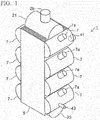
FIG. 1 is a perspective view of a multistage bath condenser-reboiler according to an embodiment of the present invention. -
FIG. 2 is a partially transparent perspective view of a multistage bath condenser-reboiler according to an embodiment of the present invention. -
FIG. 3 is a function explanation diagram of the core of a multistage bath condenser-reboiler according to an embodiment of the present invention. -
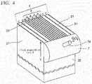
FIG. 4 is an explanatory diagram of the structure of a multistage bath condenser-reboiler according to an embodiment of the present invention. -
FIG. 5 is an explanatory diagram of the passages that form a multistage bath condenser-reboiler core according to an embodiment of the present invention. -
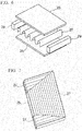
FIG. 6 is an explanatory diagram (1 of 2) of the basic structure of a multistage bath condenser-reboiler core according to an embodiment of the present invention. -
FIG. 7 is an explanatory diagram (2 of 2) of the basic structure of a multistage bath condenser-reboiler core according to an embodiment of the present invention. -
FIG. 8 is an explanatory diagram of a cryogenic air separation unit that employs a multistage bath condenser-reboiler according to an embodiment of the present invention. -
FIG. 9 is an explanatory diagram of another aspect of a liquid reservoir section of a multistage bath condenser-reboiler according to an embodiment of the present invention. -
FIG. 10 is an explanatory diagram of yet another aspect of a liquid reservoir section of a multistage bath condenser-reboiler according to an embodiment of the present invention. -
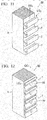
FIG. 11 is an explanatory diagram of a liquid reservoir section of a multistage bath condenser-reboiler according to another embodiment of the present invention. -
FIG. 12 is an explanatory diagram of another aspect of a liquid reservoir section of a multistage bath condenser-reboiler according to another embodiment of the present invention. -
FIG. 13 is an explanatory diagram (1 of 2) of a gas collection vessel of a multistage bath condenser-reboiler according to another embodiment of the present invention. -
FIG. 14 is an explanatory diagram (2 of 2) of a gas collection vessel of a multistage bath condenser-reboiler according to another embodiment of the present invention. -
FIG. 15 is an explanatory diagram (1 of 2) of another aspect of a multistage bath condenser-reboiler core according to another embodiment of the present invention. -
FIG. 16 is an explanatory diagram (2 of 2) of another aspect of a multistage bath condenser-reboiler core according to another embodiment of the present invention. -
FIG. 17 is an explanatory diagram of a cryogenic air separation unit that employs a multistage bath condenser-reboiler according to another embodiment of the present invention. -
FIG. 18 is an explanatory diagram of another aspect of a cryogenic air separation unit that employs a multistage bath condenser-reboiler according to another embodiment of the present invention. - Preferred embodiments of the present invention are described below, but, the present invention is not limited to the embodiments below. Various additions, omissions, substitutions and other changes may be made provided that they do not depart from the scope of the present invention.
- As illustrated in
FIG. 1 andFIG. 2 , a multistage bath condenser-reboiler 1 according to one embodiment of the present invention includes, for example, four evaporation zones aligned in the vertical direction (in order from the top, afirst evaporation zone 9 to a fourth evaporation zone 15). Here, an evaporation zone refers to a zone in which heat exchange is performed between a gas and a liquid, causing the liquid to evaporate. As illustrated inFIG. 3 , the multistage bath condenser-reboiler 1 includes: - a
heat exchanger core 5, which is composed of (i) aheat exchange section 3 and (ii)liquid communication sections 4 formed from a firstliquid communication passage 35 to a thirdliquid communication passage 39 provided on both side surfaces of theheat exchange section 3 in the stacking height direction, and - multiple stages of a
liquid reservoir section 7 formed on both sides in the width direction of theheat exchanger core 5. - Each part of this structure is described below in detail. In the following description, an example is used in which the multistage bath condenser-
reboiler 1 is used as the main condenser in a cryogenic air separation unit that condenses nitrogen gas and evaporates liquid oxygen by inducing heat exchange between the nitrogen gas and the liquid oxygen. - The
heat exchange section 3 is a device that causes heat exchange between the liquid oxygen and nitrogen gas flowing therein, thereby condensing the nitrogen gas and evaporating the liquid oxygen, and is composed ofcondensation passages 17 andevaporation passages 19 stacked adjacent to each other. - In the present embodiment, as illustrated in
FIG. 3 , theheat exchange section 3 is formed by stacking four layers of condensation passages (A) and five layers of evaporation passages (B). - As illustrated in
FIG. 6 , thecondensation passages 17 andevaporation passages 19 have a so-called plate fin type configuration formed by stacking plates 25 (parting sheets), fins 27 (corrugation fins), and side bars 29 or the like. Theplates 25 andfins 27 form flow channels, and the side bars 29 partition these flow channels while also having a reinforcing function. InFIG. 3 andFIG. 5 , the side bars 29 are shaded black. The direction of flow in the flow channels formed by stacking theplates 25 andfins 27 is determined by the orientation of thefins 27. By combiningmultiple fins 27 in different orientations, flow channels that flow in various directions can be formed, and as illustrated inFIG. 7 for example, by combining vertically orientedfins 27 and horizontally orientedfins 27, flow channels can be formed that flow from a horizontal direction to a vertical direction, and then from a vertical direction to a horizontal direction. - The
condensation passages 17 are formed using vertically oriented fins, and as illustrated inFIG. 3 orFIG. 5 , the flow channels are formed so as to communicate from the top end surface of theheat exchanger core 5 to the bottom end surface. The nitrogen gas flows in from the top ends of thecondensation passages 17, cools as is passes through the inside of the condensation passages, and flows out from the bottom ends as liquid nitrogen. - As illustrated in
FIG. 3 andFIG. 5 , theevaporation passages 19 are provided independently in each evaporation zone, and as illustrated inFIG. 5 , are formed by arranging fins that are oriented horizontally relative to the width direction of theheat exchanger core 5 and fins that are oriented vertically and communicate with the horizontally oriented fins. The liquid oxygen held in theliquid reservoir section 7 of eachevaporation passage 19 flows in from an evaporationinlet flow channel 19a formed from the lower horizontally oriented fins, rises along the vertically oriented fins while evaporating, and is returned to theliquid reservoir section 7 in the form of a vapor-liquid two-phase fluid through evaporationoutlet flow channels 19b formed from the upper horizontally oriented fins. - As illustrated in
FIG. 2 , at the top end of theheat exchanger core 5, anitrogen gas header 21 is provided which distributes the nitrogen gas to the plurality ofcondensation passages 17, and a nitrogengas inlet pipe 21 a is provided on thenitrogen gas header 21. - Furthermore, as illustrated in
FIG. 2 , at the bottom end of theheat exchanger core 5, aliquid nitrogen header 23 is provided which collects the liquid nitrogen condensed in thecondensation passages 17, and the liquid nitrogen collected in theliquid nitrogen header 23 is extracted through a liquid nitrogen extraction pipe not shown in the figure. - The first
liquid communication passage 35 to thirdliquid communication passage 39 form aliquid communication section 4, and are provided on both sides in the stacking height direction of theheat exchange section 3. As illustrated inFIG. 3 , the secondliquid communication passage 37 is formed fromplates 31 and fins in layers D on the side surfaces of theheat exchange section 3, and the first liquid communication passage and third liquid communication passage are formed further on the outward side of the secondliquid communication passage 37 by providing fins andplates 31 in layers C. -
FIG. 5 illustrates an example of the fin configuration of the firstliquid communication passage 35 to thirdliquid communication passage 39 which, in a similar manner to the evaporation passages, combine vertically oriented fins and horizontally oriented fins. - For the sake of simplicity,
FIG. 5 omits some of the lines that represent the vertically oriented fins. Fins with low pressure loss (for example, fins with a larger pitch) are preferably used as the fins in the firstliquid communication passage 35 to thirdliquid communication passage 39 to allow the liquid oxygen to flow down smoothly. - The first
liquid communication passage 35 is a passage that communicates from thefirst evaporation zone 9 to thesecond evaporation zone 11, and the thirdliquid communication passage 39 is a passage that communicates from thethird evaporation zone 13 to thefourth evaporation zone 15, with both of these communication passages formed in the layer C. Furthermore, the secondliquid communication passage 37 is a passage that communicates from thesecond evaporation zone 11 to thethird evaporation zone 13, and is formed in the layer D. - In the layers C and D which constitute the
liquid communication section 4, parts that do not function as passages (dummy passages) are formed, and these dummy passages are indicated by crosshatching inFIG. 3 andFIG. 5 . - At the top of the first and third
liquid communication passages inlet flow channel 35a and a third communicatinginlet flow channel 39a respectively, each formed from horizontally oriented fins into which liquid oxygen is introduced from theliquid reservoir sections 7 of the first andthird evaporation zones liquid communication passages outlet flow channel 35b and a third communicatingoutlet flow channel 39b respectively, each formed from horizontally oriented fins that guide liquid oxygen to theliquid reservoir sections 7 of the second andfourth evaporation zones - In a similar manner, a second communicating
inlet flow channel 37a is formed at the top of the secondliquid communication passage 37, and a second communicatingoutlet flow channel 37b is formed at the bottom of the secondliquid communication passage 37. - In this manner, because a liquid communication section composed of the first
liquid communication passage 35 to thirdliquid communication passage 39 can be formed by providingplates 31 and fins on the side surfaces of theheat exchange section 3, the structure can be made more simple and compact than conventional condensers in which communication means passages are composed of piping. - Furthermore, by using the configuration described above, the
liquid communication sections 4 and theheat exchange section 3 can be manufactured integrally as a plate fin typeheat exchanger core 5. Specifically, theheat exchanger core 5 can be produced by assembling theplates 25, thefins 27 and the side bars 29 of theheat exchange section 3 and theliquid communication sections 4 that constitute the heat exchanger core 5 (as illustrated inFIG. 6 ), and then vacuum brazing the resulting assembly in a furnace. - Furthermore, because the
communication channel sections 4 of the firstliquid communication passage 35 to thirdliquid communication passage 39 are provided on the outside surfaces of theheat exchange section 3 rather than the inside surfaces, heat exchange with the fluid in thecondensation passages 17 can be avoided. - In the example illustrated in
FIG. 3 andFIG. 4 ,liquid communication sections 4 may be provided on one or both sides of theheat exchange section 3. Providingliquid communication sections 4 on both sides allows the liquid oxygen to flow downward more smoothly. - The entire throughput flow of liquid oxygen is supplied to the
liquid reservoir section 7 of thefirst evaporation zone 9, and because a substantially equivalent amount is evaporated in each evaporation zone, the flow rate through the communication passages decreases in order from the firstliquid communication passage 35 to the secondliquid communication passage 37 and then the thirdliquid communication passage 39. Accordingly, the size of the opening of the inlet (communicating inlet flow channel) of each communication passage is changed to provide the same fluid resistance, thereby realizing a uniform liquid head in each liquid reservoir. - A
liquid reservoir section 7 is provided in each evaporation zone on at least one side surface of theheat exchanger core 5 in the width direction. In the present example, as illustrated inFIG. 1 andFIG. 2 ,liquid reservoir sections 7 are provided in each evaporation zone on both side surfaces of theheat exchanger core 5 in the width direction, and each liquid reservoir section is an enclosed space. InFIG. 5 , theliquid reservoir sections 7 on one side of theheat exchanger core 5 are not illustrated in the drawing. - A
liquid inlet port 41 through which a liquid (liquid oxygen) can be introduced from outside the device is provided on theliquid reservoir section 7 of thefirst evaporation zone 9, and aliquid discharge port 43 through which a liquid (liquid oxygen) can be discharged externally is provided on theliquid reservoir section 7 of the fourth evaporation zone 15 (seeFIG. 2 ). - Furthermore, the
liquid reservoir sections 7 also function as collectors of oxygen gas, and an evaporationgas extraction port 7a is provided in eachliquid reservoir section 7 for the purpose of extracting the evaporated gas (oxygen gas) that flows out to the reservoir section (seeFIG. 2 ). - A method for performing heat exchange between nitrogen gas and liquid oxygen using the multistage bath condenser-
reboiler 1 of the configuration described above is described below, together with a description of the operation of the multistage bath condenser-reboiler 1. - Liquid oxygen is introduced from outside the device via the
liquid inlet port 41 and accumulates in theliquid reservoir section 7 of thefirst evaporation zone 9. On the other hand, nitrogen gas is introduced into thecondensation passages 17 via thenitrogen gas header 21. - Head pressure causes the liquid oxygen accumulated in the
liquid reservoir section 7 to flow into theevaporation passage 19 from the evaporationinlet flow channel 19a, and the liquid surface levels inside theliquid reservoir section 7 and theevaporation passage 19 reach the same height. - When nitrogen gas passes through the
condensation passages 17 in this state, heat exchange occurs between the nitrogen gas and the liquid oxygen in theevaporation passage 19, a portion of the liquid oxygen undergoes evaporation and gasification to become oxygen gas, and the liquid oxygen in theevaporation passage 19 becomes a gas-liquid mixture (vapor-liquid two-phase fluid). Due to the difference in density from the liquid oxygen inside theliquid reservoir section 7, a rising flow is generated in theevaporation passage 19 and is discharged from the evaporationoutlet flow channel 19b as a vapor-liquid two-phase fluid. The discharged evaporated oxygen gas is extracted from the evaporationgas extraction port 7a of theliquid reservoir section 7, and the liquid oxygen that did not evaporate returns to theliquid reservoir section 7, forming a circulating flow between theliquid reservoir section 7 and the evaporation passage 19 (a thermosiphoning effect). - When the liquid surface level in the
liquid reservoir section 7 reaches or exceeds the height of the first communicatinginlet flow channel 35a, the liquid oxygen flows from the first communicatinginlet flow channel 35a into thefirst communication passage 35, is discharged from the first communicatingoutlet flow channel 35b, and accumulates in theliquid reservoir section 7 of the second evaporation zone. - Once liquid oxygen has accumulated in the
liquid reservoir section 7 of thesecond evaporation zone 11, then in a similar manner to thefirst evaporation zone 9, the liquid oxygen flows from the evaporationinlet flow channel 19a into theevaporation passage 19 and is discharged from the evaporationoutlet flow channel 19b as a vapor-liquid two-phase fluid, and when the liquid surface level in theliquid reservoir section 7 reaches or exceeds the height of the second communicatinginlet flow channel 37a, the liquid oxygen flows into the secondcommunication flow channel 37 and enters theliquid reservoir section 7 of the lower-stagethird evaporation zone 13 via the second communicatingoutlet flow channel 37b. - The flow of liquid oxygen from the
third evaporation zone 13 into thefourth evaporation zone 15 occurs in a similar manner. The liquid oxygen that accumulates in theliquid reservoir section 7 of thefourth evaporation zone 15 is extracted via theliquid discharge port 43 so that the liquid surface level remains constant. - On the other hand, the nitrogen gas undergoes heat exchange with the liquid oxygen in the
adjacent evaporation passages 19 while passing through thecondensation passages 17, condenses (is liquefied) and flows down from the bottom end of thecondensation passages 17, and is extracted via theliquid nitrogen header 23 and the liquid nitrogen extraction pipe. - As is apparent from this description of the operation of the device, because a vapor-liquid two-phase fluid is discharged from the evaporation
outlet flow channel 19b to theliquid reservoir section 7, it is preferable that the liquid surface level of theliquid reservoir section 7 is below the evaporationoutlet flow channel 19b so as not to impede this discharge. Accordingly, the heights of the communicating inlet flow channels (the first communicatinginlet flow channel 35a, the second communicatinginlet flow channel 37a and the third communicatinginlet flow channel 39a) in each evaporation zone are preferably set lower than the evaporationoutlet flow channels 19b. - In the
liquid reservoir sections 7, in the vicinity of the evaporationinlet flow channels 19a, the liquid oxygen flows from theliquid reservoir section 7 toward the inward direction of theheat exchanger core 5, whereas in the vicinity of the communicating outlet flow channels (the first communicatingoutlet flow channel 35b, the second communicatingoutlet flow channel 37b and the third communicatingoutlet flow channel 39b), the liquid oxygen flows from theheat exchanger core 5 toward theliquid reservoir section 7. Accordingly, if the evaporationinlet flow channel 19a and the communicating outlet flow channels are near each other, there is a possibility that the opposing flows may interfere with each other, causing stagnation in the flow, and therefore the evaporationinlet flow channel 19a and the communicating outlet flow channels are preferably placed as far apart as possible. For example, the height position of the evaporationinlet flow channel 19a may be displaced relative to the height position of the communicating outlet flow channels. - It is particularly preferable that the height position of the evaporation
inlet flow channel 19a is lower than the height position of the communicating outlet flow channels. By employing such a configuration, the liquid oxygen can still flow into the evaporationinlet flow channel 19a in situations such as at startup when little liquid oxygen has accumulated in theliquid reservoir section 7, -
FIG. 8 illustrates an example of using the multistage bath condenser-reboiler 1 of the above configuration as the main condenser in a cryogenicair separation unit 51. -
FIG. 8 illustrates an example in which a high-pressure column 53 and a low-pressure column 55 are provided as separate devices units, and the device illustrated inFIG. 1 is used as the main condenser. Components inFIG. 8 that are the same as those illustrated inFIG. 1 are assigned the same reference signs. The high-pressure column 53 is operated at, for example, an internal pressure of 6.0 bar, and the low-pressure column 55 is operated at, for example, an internal pressure of 1.4 bar. Feed air is supplied in the high-pressure column 53, and through distillation, oxygen-enriched liquid is produced at the bottom of the column and nitrogen gas is produced at the top of the column. All or some of this nitrogen gas is supplied to the multistage bath condenser-reboiler 1, undergoes condensation and liquefaction, and is supplied to the tops of the high-pressure column and the low-pressure column as a reflux liquid. - In the low-
pressure column 55, as a result of distillation of the oxygen-enriched liquid in the bottom of the high-pressure column as the main raw material, low-pressure nitrogen gas is produced at the top of the column and liquid oxygen is produced at the bottom of the column, and this liquid oxygen is supplied to the multistage bath condenser-reboiler 1, undergoes evaporation and gasification, and is returned to the bottom of the low-pressure column as a rising gas. - In the above description, as illustrated in
FIG. 1 ,FIG. 2 andFIG. 5 , an example was described in which a dome-shapedliquid reservoir section 7 was formed in each evaporation zone. However, for example, as illustrated inFIG. 9 , the interior of theliquid reservoir section 7 may be demarcated bypartition plates 45. Alternatively, as illustrated inFIG. 10 , a configuration may be used in which dome-shaped headers are used which individually cover the evaporationinlet flow channel 19a and communicating outlet flow channel, and the evaporationoutlet flow channel 19b and communicating inlet flow channel (seeFIG. 5 ) in eachliquid reservoir section 7 in each evaporation zone, with the headers connected to each other by connectingpipes 59. By employing this construction, theliquid reservoir section 7 can be made more compact. - In the above description, an example was described in which the
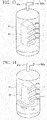
liquid reservoir sections 7 have the roles of storing liquid oxygen and of collecting oxygen gas, but theliquid reservoir section 7 need not necessarily have the role of collecting oxygen gas. Examples of such configurations are shown inFIG. 17 . andFIG. 12. FIG. 11 illustrates a modification of the embodiment shown inFIG. 1 , andFIG. 12 illustrates a modification of the embodiment shown inFIG. 10 . Both are open-type multistage bath condenser-reboilers 60 in which theliquid reservoir sections 7 are open at the top. - Components in
FIG. 11 and FIG. 12 that are the same as those inFIG. 1 andFIG. 10 are assigned the same reference signs. - As illustrated in
FIG. 13 , the open-type multistage bath condenser-reboiler 60 is placed in agas collection vessel 61 that covers the multistage bath condenser-reboiler 60 in its entirety, so that the evaporated gas (oxygen gas) that flows out to the liquid reservoir sections collects in thegas collection vessel 61. - Furthermore, in the case of the devices shown in
FIG. 11 and FIG. 12 , theliquid reservoir section 7 may be omitted from the lowest-stage evaporation zone, allowing the liquid oxygen to collect in thegas collection vessel 61 as illustrated inFIG. 14 . In this case, as illustrated inFIG. 15 , it is preferable that in the lowest-stage evaporation zone, the evaporationinlet flow channels 19a are provided on the bottom end surfaces of the evaporation passages B, and it is particularly preferable that theliquid nitrogen header 23 is provided on the side surface of the bottom end of the condensation passages A, as illustrated inFIG. 16 for example. -
FIG. 17 illustrates a cryogenicair separation unit 63 that uses an open-type multistage bath condenser-reboiler 60 such as that described above as the main condenser - The cryogenic
air separation unit 63 is a modification of the cryogenicair separation unit 51 illustrated inFIG. 8 , and uses the device illustrated inFIG. 15 as the main condenser. Components inFIG. 17 that are the same as those inFIG. 8 are assigned the same reference signs. In this case, the multistage bath condenser-reboiler 60 is housed within thegas collection vessel 61, oxygen gas is extracted from the top of thegas collection vessel 61 through anextraction pipe 61 a and supplied to the low-pressure column 55, and liquid oxygen is extracted from the bottom of thegas collection vessel 61 as a product. -
FIG. 18 illustrates a cryogenicair separation unit 65 as another aspect of a cryogenic air separation unit that uses the open-type multistage bath condenser-reboiler 60. In the air liquefaction andseparation device 65, the high-pressure column 53 and the low-pressure column 55 are constructed as a single integrated device, and the multistage bath condenser-reboiler 60 is housed in the sump of the low-pressure column 55. Components inFIG. 18 that are the same as those inFIG. 8 andFIG. 17 are assigned the same reference signs. In this case, the bottom section of the low-pressure column 55 serves the role of a gas accumulation vessel (for accumulating liquid oxygen and collecting oxygen gas). - In the
embodiment 1 and the embodiment 2 described above, an example was described in which, because four stages of evaporation zones were provided, a firstliquid communication passage 35 through to a thirdliquid communication passage 39 were formed, but the number, shape and other attributes of the liquid communication passages may be changed as required in accordance with the number of evaporation zones. - A multistage bath condenser-reboiler can be obtained in which the liquid reservoirs provided in the condensation evaporator core and the means by which the liquid reservoirs communicate have a simple construction, enabling a compact design.
-
- Layer A
- Condensation passage
- Layer B
- Evaporation passage
- Layer C
- Liquid communication passage
- Layer D
- Liquid communication passage
- I
- Multistage bath condenser-reboiler (embodiment 1)
- 3
- Heat exchange section
- 4
- Liquid communication section
- 5
- Heat exchanger core
- 7
- Liquid reservoir section
- 7a
- Evaporation gas extraction port
- 9
- First evaporation zone
- 11
- Second evaporation zone
- 13
- Third evaporation zone
- 15
- Fourth evaporation zone
- 17
- Condensation passage
- 19
- Evaporation passage
- 19a
- Evaporation inlet flow channel
- 19b
- Evaporation outlet flow channel
- 21
- Nitrogen gas header
- 21a
- Nitrogen gas inlet port
- 23
- Liquid nitrogen header
- 25
- Plate
- 27
- Fin
- 29
- Side bar
- 31
- Passage formation plates
- 35
- First liquid communication passage
- 35a
- First communicating inlet flow channel
- 35b
- First communicating outlet flow channel
- 37
- Second liquid communication passage
- 37a
- Second communicating inlet flow channel
- 37b
- Second communicating outlet flow channel
- 39
- Third liquid communication passage
- 39a
- Third communicating inlet flow channel
- 39b
- Third communicating outlet flow channel
- 41
- Liquid inlet port
- 43
- Liquid discharge port
- 45
- Partition plate
- 51
- Cryogenic air separation unit
- 53
- High-pressure column
- 55
- Low-pressure column
- 59
- Connecting pipe
- 60
- Multistage bath condenser-reboiler (embodiment 2)
- 61
- Gas collection vessel
- 61a
- Extraction pipe
- 63
- Cryogenic air separation unit (other aspect)
- 65
- Cryogenic air separation unit (yet another aspect)
Claims (9)
- A multistage bath condenser-reboiler, comprising: condensation passages which communicate in the vertical direction and through which a gas flows and condenses, evaporation passages which are partitioned into multiple stages through which a liquid flows that undergoes heat exchange with the gas and evaporates, one or more stages of liquid reservoir sections which hold liquid supplied to and discharged from the evaporation passages, and liquid communication passages through which the liquid in the liquid reservoir sections flows from upper liquid reservoir sections to lower liquid reservoir sections, wherein
the multistage bath condenser-reboiler comprises:a heat exchanger core comprising (i) a heat exchange section formed by adjacently stacking the condensation passages and the evaporation passages formed from plates and fins, and (ii) a liquid communication section formed from the liquid communication passages provided on at least one side surface in a stacking height direction of the heat exchange section, andone or more stages of the liquid reservoir section formed on at least one side surface in a width direction of the heat exchanger core so as to correspond with a number of stages of the evaporation passages. - The multistage bath condenser-reboiler according to Claim 1, wherein in the evaporation passages are formed evaporation inlet flow channels through which the liquid in the liquid reservoir sections is introduced into the partitioned evaporation passages, and evaporation outlet flow channels which discharge a rising vapor-liquid two-phase fluid into the liquid reservoir sections, and in the liquid communication passages are formed communicating inlet flow channels which introduce the liquid in the liquid reservoir sections into the liquid communication passages, and communicating outlet flow channels from which liquid flows out into a lower liquid reservoir section.
- The multistage bath condenser-reboiler according to Claim 2, wherein an inlet of
the communicating inlet flow channel is provided at a position below a position of an outlet of the evaporation outlet flow channel. - The multistage bath condenser-reboiler according to Claim 2, wherein a height position of an inlet of the evaporation inlet flow channel is offset with respect to a height position of an outlet of the communicating outlet flow channel.
- The multistage bath condenser-reboiler according to any one of Claims 1 to 4, wherein each liquid reservoir section is an enclosed space, and in each liquid reservoir section is provided an evaporation gas extraction port through which evaporated gas that flows out to the liquid reservoir section is extracted.
- The multistage bath condenser-reboiler according to Claim 5, wherein, in the liquid reservoir section, in an uppermost liquid reservoir section is provided a liquid inlet port into which liquid is introduced from externally, and in a lowermost liquid reservoir section is provided a liquid discharge port from which liquid is discharged externally.
- The multistage bath condenser-reboiler according to any one of Claims 1 to 4, wherein the liquid reservoir sections are open, and the evaporator further comprises a gas collection vessel which collects evaporated gas that flows out into the liquid reservoir sections.
- The multistage bath condenser-reboiler according to any one of Claims 1 to 7, wherein the liquid reservoir sections are provided on both sides in a width direction of the heat exchanger core.
- The multistage bath condenser-reboiler according to any one of Claims 1 to 8, wherein the liquid communication passages are provided on both side surfaces in a stacking height direction of the heat exchanger core.
Applications Claiming Priority (2)
| Application Number | Priority Date | Filing Date | Title |
|---|---|---|---|
| JP2014169825A JP6087326B2 (en) | 2014-08-22 | 2014-08-22 | Multistage condensing evaporator |
| PCT/JP2015/073553 WO2016027889A1 (en) | 2014-08-22 | 2015-08-21 | Multistage liquid-reservoir-type condensation evaporator |
Publications (3)
| Publication Number | Publication Date |
|---|---|
| EP3184944A1 true EP3184944A1 (en) | 2017-06-28 |
| EP3184944A4 EP3184944A4 (en) | 2018-03-21 |
| EP3184944B1 EP3184944B1 (en) | 2021-12-08 |
Family
ID=55350828
Family Applications (1)
| Application Number | Title | Priority Date | Filing Date |
|---|---|---|---|
| EP15834547.0A Active EP3184944B1 (en) | 2014-08-22 | 2015-08-21 | Multistage liquid-reservoir-type condensation evaporator |
Country Status (5)
| Country | Link |
|---|---|
| US (1) | US10408535B2 (en) |
| EP (1) | EP3184944B1 (en) |
| JP (1) | JP6087326B2 (en) |
| CN (1) | CN106662395B (en) |
| WO (1) | WO2016027889A1 (en) |
Cited By (1)
| Publication number | Priority date | Publication date | Assignee | Title |
|---|---|---|---|---|
| EP3919439A4 (en) * | 2019-01-28 | 2022-10-26 | Taiyo Nippon Sanso Corporation | MULTI-STAGE TANK CONDENSER-EVAPORATOR, AND NITROGEN PRODUCTION DEVICE USING A MULTI-STAGE TANK CONDENSER-EVAPORATOR |
Families Citing this family (7)
| Publication number | Priority date | Publication date | Assignee | Title |
|---|---|---|---|---|
| JP7103816B2 (en) * | 2018-03-29 | 2022-07-20 | 大陽日酸株式会社 | Argon production equipment and method by air liquefaction separation |
| CN108592678B (en) * | 2018-05-21 | 2023-09-01 | 杭州中泰深冷技术股份有限公司 | Multistage type outer siphon plate-fin heat exchanger and method thereof |
| CN110307742A (en) * | 2019-07-26 | 2019-10-08 | 杭州中泰深冷技术股份有限公司 | Multi-stage separated plate-fin heat exchanger and heat exchange method |
| JP7356334B2 (en) | 2019-12-17 | 2023-10-04 | 大陽日酸株式会社 | Multi-stage reservoir condensing evaporator, air separation device equipped with the multi-stage reservoir condensing evaporator |
| US11674750B2 (en) * | 2020-06-04 | 2023-06-13 | Praxair Technology, Inc. | Dual column nitrogen producing air separation unit with split kettle reboil and integrated condenser-reboiler |
| CN114132139B (en) * | 2020-09-03 | 2025-11-28 | 浙江三花汽车零部件有限公司 | Thermal management assembly |
| JP7308237B2 (en) * | 2021-03-12 | 2023-07-13 | 大陽日酸株式会社 | Partial condenser, overhead partial condenser, air separation unit |
Family Cites Families (6)
| Publication number | Priority date | Publication date | Assignee | Title |
|---|---|---|---|---|
| JPS60253782A (en) | 1984-05-30 | 1985-12-14 | 日本酸素株式会社 | Condenser for large-sized air separator |
| JP2787593B2 (en) * | 1989-06-02 | 1998-08-20 | 日本酸素株式会社 | Evaporator |
| JPH06257981A (en) * | 1993-03-09 | 1994-09-16 | Nippon Sanso Kk | Condensing evaporator |
| US5709264A (en) * | 1996-03-18 | 1998-01-20 | The Boc Group, Inc. | Heat exchanger |
| DE10027139A1 (en) | 2000-05-31 | 2001-12-06 | Linde Ag | Multi-storey bathroom condenser |
| JP6051952B2 (en) | 2013-03-04 | 2016-12-27 | 新日鐵住金株式会社 | Fuel control method and fuel control apparatus for blast furnace gas fired boiler |
-
2014
- 2014-08-22 JP JP2014169825A patent/JP6087326B2/en active Active
-
2015
- 2015-08-21 EP EP15834547.0A patent/EP3184944B1/en active Active
- 2015-08-21 WO PCT/JP2015/073553 patent/WO2016027889A1/en not_active Ceased
- 2015-08-21 CN CN201580044530.9A patent/CN106662395B/en active Active
- 2015-08-21 US US15/502,250 patent/US10408535B2/en active Active
Cited By (2)
| Publication number | Priority date | Publication date | Assignee | Title |
|---|---|---|---|---|
| EP3919439A4 (en) * | 2019-01-28 | 2022-10-26 | Taiyo Nippon Sanso Corporation | MULTI-STAGE TANK CONDENSER-EVAPORATOR, AND NITROGEN PRODUCTION DEVICE USING A MULTI-STAGE TANK CONDENSER-EVAPORATOR |
| US12130081B2 (en) | 2019-01-28 | 2024-10-29 | Taiyo Nippon Sanso Corporation | Multistage liquid storage-type condenser-evaporator and nitrogen production device using the same |
Also Published As
| Publication number | Publication date |
|---|---|
| WO2016027889A1 (en) | 2016-02-25 |
| US10408535B2 (en) | 2019-09-10 |
| EP3184944A4 (en) | 2018-03-21 |
| JP2016044894A (en) | 2016-04-04 |
| US20170227284A1 (en) | 2017-08-10 |
| CN106662395B (en) | 2019-09-13 |
| CN106662395A (en) | 2017-05-10 |
| EP3184944B1 (en) | 2021-12-08 |
| JP6087326B2 (en) | 2017-03-01 |
Similar Documents
| Publication | Publication Date | Title |
|---|---|---|
| EP3184944B1 (en) | Multistage liquid-reservoir-type condensation evaporator | |
| JP4803470B2 (en) | Heat exchange type distillation equipment | |
| KR102112478B1 (en) | Heat integrated distillation apparatus | |
| US10016699B2 (en) | Distillation column | |
| JP6037575B2 (en) | Distillation station | |
| US10048004B2 (en) | Condenser-reboiler system and method | |
| KR20080013779A (en) | Reflux condenser | |
| JP7382352B2 (en) | Multi-stage reservoir condenser evaporator and nitrogen production equipment using multi-stage reservoir condenser evaporator | |
| JP7103816B2 (en) | Argon production equipment and method by air liquefaction separation | |
| WO2000020812A1 (en) | Downflow liquid film type condensation evaporator | |
| JP7308237B2 (en) | Partial condenser, overhead partial condenser, air separation unit | |
| JP2017090035A (en) | Plate heat exchanger/condensation vaporizer and low temperature separation method of air | |
| US9476641B2 (en) | Down-flow condenser reboiler system for use in an air separation plant | |
| JP7356334B2 (en) | Multi-stage reservoir condensing evaporator, air separation device equipped with the multi-stage reservoir condensing evaporator | |
| JPH0789008B2 (en) | Condensing evaporator | |
| US20180112913A1 (en) | Plate heat exchanger condenser-evaporator and process for low-temperature air separation |
Legal Events
| Date | Code | Title | Description |
|---|---|---|---|
| STAA | Information on the status of an ep patent application or granted ep patent |
Free format text: STATUS: THE INTERNATIONAL PUBLICATION HAS BEEN MADE |
|
| PUAI | Public reference made under article 153(3) epc to a published international application that has entered the european phase |
Free format text: ORIGINAL CODE: 0009012 |
|
| STAA | Information on the status of an ep patent application or granted ep patent |
Free format text: STATUS: REQUEST FOR EXAMINATION WAS MADE |
|
| 17P | Request for examination filed |
Effective date: 20170207 |
|
| AK | Designated contracting states |
Kind code of ref document: A1 Designated state(s): AL AT BE BG CH CY CZ DE DK EE ES FI FR GB GR HR HU IE IS IT LI LT LU LV MC MK MT NL NO PL PT RO RS SE SI SK SM TR |
|
| AX | Request for extension of the european patent |
Extension state: BA ME |
|
| DAV | Request for validation of the european patent (deleted) | ||
| DAX | Request for extension of the european patent (deleted) | ||
| A4 | Supplementary search report drawn up and despatched |
Effective date: 20180220 |
|
| RIC1 | Information provided on ipc code assigned before grant |
Ipc: F28D 9/00 20060101ALI20180214BHEP Ipc: F25J 3/04 20060101ALI20180214BHEP Ipc: F25J 3/02 20060101ALI20180214BHEP Ipc: F25J 5/00 20060101AFI20180214BHEP Ipc: B01D 5/00 20060101ALI20180214BHEP Ipc: F28F 3/08 20060101ALI20180214BHEP |
|
| GRAP | Despatch of communication of intention to grant a patent |
Free format text: ORIGINAL CODE: EPIDOSNIGR1 |
|
| STAA | Information on the status of an ep patent application or granted ep patent |
Free format text: STATUS: GRANT OF PATENT IS INTENDED |
|
| INTG | Intention to grant announced |
Effective date: 20210709 |
|
| GRAS | Grant fee paid |
Free format text: ORIGINAL CODE: EPIDOSNIGR3 |
|
| GRAA | (expected) grant |
Free format text: ORIGINAL CODE: 0009210 |
|
| STAA | Information on the status of an ep patent application or granted ep patent |
Free format text: STATUS: THE PATENT HAS BEEN GRANTED |
|
| AK | Designated contracting states |
Kind code of ref document: B1 Designated state(s): AL AT BE BG CH CY CZ DE DK EE ES FI FR GB GR HR HU IE IS IT LI LT LU LV MC MK MT NL NO PL PT RO RS SE SI SK SM TR |
|
| REG | Reference to a national code |
Ref country code: GB Ref legal event code: FG4D |
|
| REG | Reference to a national code |
Ref country code: AT Ref legal event code: REF Ref document number: 1454080 Country of ref document: AT Kind code of ref document: T Effective date: 20211215 Ref country code: CH Ref legal event code: EP |
|
| REG | Reference to a national code |
Ref country code: DE Ref legal event code: R096 Ref document number: 602015075662 Country of ref document: DE |
|
| REG | Reference to a national code |
Ref country code: IE Ref legal event code: FG4D |
|
| REG | Reference to a national code |
Ref country code: LT Ref legal event code: MG9D |
|
| REG | Reference to a national code |
Ref country code: NL Ref legal event code: MP Effective date: 20211208 |
|
| PG25 | Lapsed in a contracting state [announced via postgrant information from national office to epo] |
Ref country code: RS Free format text: LAPSE BECAUSE OF FAILURE TO SUBMIT A TRANSLATION OF THE DESCRIPTION OR TO PAY THE FEE WITHIN THE PRESCRIBED TIME-LIMIT Effective date: 20211208 Ref country code: LT Free format text: LAPSE BECAUSE OF FAILURE TO SUBMIT A TRANSLATION OF THE DESCRIPTION OR TO PAY THE FEE WITHIN THE PRESCRIBED TIME-LIMIT Effective date: 20211208 Ref country code: FI Free format text: LAPSE BECAUSE OF FAILURE TO SUBMIT A TRANSLATION OF THE DESCRIPTION OR TO PAY THE FEE WITHIN THE PRESCRIBED TIME-LIMIT Effective date: 20211208 Ref country code: BG Free format text: LAPSE BECAUSE OF FAILURE TO SUBMIT A TRANSLATION OF THE DESCRIPTION OR TO PAY THE FEE WITHIN THE PRESCRIBED TIME-LIMIT Effective date: 20220308 |
|
| REG | Reference to a national code |
Ref country code: AT Ref legal event code: MK05 Ref document number: 1454080 Country of ref document: AT Kind code of ref document: T Effective date: 20211208 |
|
| PG25 | Lapsed in a contracting state [announced via postgrant information from national office to epo] |
Ref country code: SE Free format text: LAPSE BECAUSE OF FAILURE TO SUBMIT A TRANSLATION OF THE DESCRIPTION OR TO PAY THE FEE WITHIN THE PRESCRIBED TIME-LIMIT Effective date: 20211208 Ref country code: NO Free format text: LAPSE BECAUSE OF FAILURE TO SUBMIT A TRANSLATION OF THE DESCRIPTION OR TO PAY THE FEE WITHIN THE PRESCRIBED TIME-LIMIT Effective date: 20220308 Ref country code: LV Free format text: LAPSE BECAUSE OF FAILURE TO SUBMIT A TRANSLATION OF THE DESCRIPTION OR TO PAY THE FEE WITHIN THE PRESCRIBED TIME-LIMIT Effective date: 20211208 Ref country code: HR Free format text: LAPSE BECAUSE OF FAILURE TO SUBMIT A TRANSLATION OF THE DESCRIPTION OR TO PAY THE FEE WITHIN THE PRESCRIBED TIME-LIMIT Effective date: 20211208 Ref country code: GR Free format text: LAPSE BECAUSE OF FAILURE TO SUBMIT A TRANSLATION OF THE DESCRIPTION OR TO PAY THE FEE WITHIN THE PRESCRIBED TIME-LIMIT Effective date: 20220309 Ref country code: ES Free format text: LAPSE BECAUSE OF FAILURE TO SUBMIT A TRANSLATION OF THE DESCRIPTION OR TO PAY THE FEE WITHIN THE PRESCRIBED TIME-LIMIT Effective date: 20211208 |
|
| PG25 | Lapsed in a contracting state [announced via postgrant information from national office to epo] |
Ref country code: NL Free format text: LAPSE BECAUSE OF FAILURE TO SUBMIT A TRANSLATION OF THE DESCRIPTION OR TO PAY THE FEE WITHIN THE PRESCRIBED TIME-LIMIT Effective date: 20211208 |
|
| PG25 | Lapsed in a contracting state [announced via postgrant information from national office to epo] |
Ref country code: SM Free format text: LAPSE BECAUSE OF FAILURE TO SUBMIT A TRANSLATION OF THE DESCRIPTION OR TO PAY THE FEE WITHIN THE PRESCRIBED TIME-LIMIT Effective date: 20211208 Ref country code: SK Free format text: LAPSE BECAUSE OF FAILURE TO SUBMIT A TRANSLATION OF THE DESCRIPTION OR TO PAY THE FEE WITHIN THE PRESCRIBED TIME-LIMIT Effective date: 20211208 Ref country code: RO Free format text: LAPSE BECAUSE OF FAILURE TO SUBMIT A TRANSLATION OF THE DESCRIPTION OR TO PAY THE FEE WITHIN THE PRESCRIBED TIME-LIMIT Effective date: 20211208 Ref country code: PT Free format text: LAPSE BECAUSE OF FAILURE TO SUBMIT A TRANSLATION OF THE DESCRIPTION OR TO PAY THE FEE WITHIN THE PRESCRIBED TIME-LIMIT Effective date: 20220408 Ref country code: EE Free format text: LAPSE BECAUSE OF FAILURE TO SUBMIT A TRANSLATION OF THE DESCRIPTION OR TO PAY THE FEE WITHIN THE PRESCRIBED TIME-LIMIT Effective date: 20211208 Ref country code: CZ Free format text: LAPSE BECAUSE OF FAILURE TO SUBMIT A TRANSLATION OF THE DESCRIPTION OR TO PAY THE FEE WITHIN THE PRESCRIBED TIME-LIMIT Effective date: 20211208 |
|
| PG25 | Lapsed in a contracting state [announced via postgrant information from national office to epo] |
Ref country code: PL Free format text: LAPSE BECAUSE OF FAILURE TO SUBMIT A TRANSLATION OF THE DESCRIPTION OR TO PAY THE FEE WITHIN THE PRESCRIBED TIME-LIMIT Effective date: 20211208 Ref country code: AT Free format text: LAPSE BECAUSE OF FAILURE TO SUBMIT A TRANSLATION OF THE DESCRIPTION OR TO PAY THE FEE WITHIN THE PRESCRIBED TIME-LIMIT Effective date: 20211208 |
|
| REG | Reference to a national code |
Ref country code: DE Ref legal event code: R097 Ref document number: 602015075662 Country of ref document: DE |
|
| PG25 | Lapsed in a contracting state [announced via postgrant information from national office to epo] |
Ref country code: IS Free format text: LAPSE BECAUSE OF FAILURE TO SUBMIT A TRANSLATION OF THE DESCRIPTION OR TO PAY THE FEE WITHIN THE PRESCRIBED TIME-LIMIT Effective date: 20220408 |
|
| PLBE | No opposition filed within time limit |
Free format text: ORIGINAL CODE: 0009261 |
|
| STAA | Information on the status of an ep patent application or granted ep patent |
Free format text: STATUS: NO OPPOSITION FILED WITHIN TIME LIMIT |
|
| PG25 | Lapsed in a contracting state [announced via postgrant information from national office to epo] |
Ref country code: DK Free format text: LAPSE BECAUSE OF FAILURE TO SUBMIT A TRANSLATION OF THE DESCRIPTION OR TO PAY THE FEE WITHIN THE PRESCRIBED TIME-LIMIT Effective date: 20211208 Ref country code: AL Free format text: LAPSE BECAUSE OF FAILURE TO SUBMIT A TRANSLATION OF THE DESCRIPTION OR TO PAY THE FEE WITHIN THE PRESCRIBED TIME-LIMIT Effective date: 20211208 |
|
| 26N | No opposition filed |
Effective date: 20220909 |
|
| PG25 | Lapsed in a contracting state [announced via postgrant information from national office to epo] |
Ref country code: SI Free format text: LAPSE BECAUSE OF FAILURE TO SUBMIT A TRANSLATION OF THE DESCRIPTION OR TO PAY THE FEE WITHIN THE PRESCRIBED TIME-LIMIT Effective date: 20211208 |
|
| PG25 | Lapsed in a contracting state [announced via postgrant information from national office to epo] |
Ref country code: MC Free format text: LAPSE BECAUSE OF FAILURE TO SUBMIT A TRANSLATION OF THE DESCRIPTION OR TO PAY THE FEE WITHIN THE PRESCRIBED TIME-LIMIT Effective date: 20211208 |
|
| REG | Reference to a national code |
Ref country code: CH Ref legal event code: PL |
|
| GBPC | Gb: european patent ceased through non-payment of renewal fee |
Effective date: 20220821 |
|
| PG25 | Lapsed in a contracting state [announced via postgrant information from national office to epo] |
Ref country code: LU Free format text: LAPSE BECAUSE OF NON-PAYMENT OF DUE FEES Effective date: 20220821 Ref country code: LI Free format text: LAPSE BECAUSE OF NON-PAYMENT OF DUE FEES Effective date: 20220831 Ref country code: CH Free format text: LAPSE BECAUSE OF NON-PAYMENT OF DUE FEES Effective date: 20220831 |
|
| REG | Reference to a national code |
Ref country code: BE Ref legal event code: MM Effective date: 20220831 |
|
| PG25 | Lapsed in a contracting state [announced via postgrant information from national office to epo] |
Ref country code: IT Free format text: LAPSE BECAUSE OF FAILURE TO SUBMIT A TRANSLATION OF THE DESCRIPTION OR TO PAY THE FEE WITHIN THE PRESCRIBED TIME-LIMIT Effective date: 20211208 |
|
| PG25 | Lapsed in a contracting state [announced via postgrant information from national office to epo] |
Ref country code: IE Free format text: LAPSE BECAUSE OF NON-PAYMENT OF DUE FEES Effective date: 20220821 |
|
| P01 | Opt-out of the competence of the unified patent court (upc) registered |
Effective date: 20230713 |
|
| PG25 | Lapsed in a contracting state [announced via postgrant information from national office to epo] |
Ref country code: BE Free format text: LAPSE BECAUSE OF NON-PAYMENT OF DUE FEES Effective date: 20220831 |
|
| PG25 | Lapsed in a contracting state [announced via postgrant information from national office to epo] |
Ref country code: GB Free format text: LAPSE BECAUSE OF NON-PAYMENT OF DUE FEES Effective date: 20220821 |
|
| PG25 | Lapsed in a contracting state [announced via postgrant information from national office to epo] |
Ref country code: HU Free format text: LAPSE BECAUSE OF FAILURE TO SUBMIT A TRANSLATION OF THE DESCRIPTION OR TO PAY THE FEE WITHIN THE PRESCRIBED TIME-LIMIT; INVALID AB INITIO Effective date: 20150821 |
|
| PG25 | Lapsed in a contracting state [announced via postgrant information from national office to epo] |
Ref country code: CY Free format text: LAPSE BECAUSE OF FAILURE TO SUBMIT A TRANSLATION OF THE DESCRIPTION OR TO PAY THE FEE WITHIN THE PRESCRIBED TIME-LIMIT Effective date: 20211208 |
|
| PG25 | Lapsed in a contracting state [announced via postgrant information from national office to epo] |
Ref country code: MK Free format text: LAPSE BECAUSE OF FAILURE TO SUBMIT A TRANSLATION OF THE DESCRIPTION OR TO PAY THE FEE WITHIN THE PRESCRIBED TIME-LIMIT Effective date: 20211208 |
|
| PG25 | Lapsed in a contracting state [announced via postgrant information from national office to epo] |
Ref country code: MT Free format text: LAPSE BECAUSE OF FAILURE TO SUBMIT A TRANSLATION OF THE DESCRIPTION OR TO PAY THE FEE WITHIN THE PRESCRIBED TIME-LIMIT Effective date: 20211208 |
|
| PGFP | Annual fee paid to national office [announced via postgrant information from national office to epo] |
Ref country code: DE Payment date: 20250820 Year of fee payment: 11 |
|
| PGFP | Annual fee paid to national office [announced via postgrant information from national office to epo] |
Ref country code: FR Payment date: 20250829 Year of fee payment: 11 |
|
| PG25 | Lapsed in a contracting state [announced via postgrant information from national office to epo] |
Ref country code: TR Free format text: LAPSE BECAUSE OF FAILURE TO SUBMIT A TRANSLATION OF THE DESCRIPTION OR TO PAY THE FEE WITHIN THE PRESCRIBED TIME-LIMIT Effective date: 20211208 |