EP3184838A1 - Vehicle clutches - Google Patents
Vehicle clutches Download PDFInfo
- Publication number
- EP3184838A1 EP3184838A1 EP16002558.1A EP16002558A EP3184838A1 EP 3184838 A1 EP3184838 A1 EP 3184838A1 EP 16002558 A EP16002558 A EP 16002558A EP 3184838 A1 EP3184838 A1 EP 3184838A1
- Authority
- EP
- European Patent Office
- Prior art keywords
- clutch
- pressure plate
- wear
- ramp
- pin
- Prior art date
- Legal status (The legal status is an assumption and is not a legal conclusion. Google has not performed a legal analysis and makes no representation as to the accuracy of the status listed.)
- Granted
Links
- 230000001419 dependent effect Effects 0.000 claims abstract description 4
- 238000010276 construction Methods 0.000 description 4
- 230000005540 biological transmission Effects 0.000 description 1
- 230000000694 effects Effects 0.000 description 1
- 230000007774 longterm Effects 0.000 description 1
- 238000004519 manufacturing process Methods 0.000 description 1
- 239000002184 metal Substances 0.000 description 1
- 238000009877 rendering Methods 0.000 description 1
- 239000007787 solid Substances 0.000 description 1
Images

Classifications
-
- F—MECHANICAL ENGINEERING; LIGHTING; HEATING; WEAPONS; BLASTING
- F16—ENGINEERING ELEMENTS AND UNITS; GENERAL MEASURES FOR PRODUCING AND MAINTAINING EFFECTIVE FUNCTIONING OF MACHINES OR INSTALLATIONS; THERMAL INSULATION IN GENERAL
- F16D—COUPLINGS FOR TRANSMITTING ROTATION; CLUTCHES; BRAKES
- F16D13/00—Friction clutches
- F16D13/58—Details
- F16D13/75—Features relating to adjustment, e.g. slack adjusters
- F16D13/757—Features relating to adjustment, e.g. slack adjusters the adjusting device being located on or inside the clutch cover, e.g. acting on the diaphragm or on the pressure plate
Definitions
- This invention relates to vehicle clutches and in particular to such clutches which include a wear adjuster and which transmit drive from a vehicle engine to an associated vehicle transmission.
- a friction clutch for a motor vehicle, the clutch comprising a pressure plate biased towards an associated flywheel by a diaphragm spring, a clutch drive disc for clamping between the pressure plate and the associated flywheel, and a ramp type wear adjuster located in the thrust path between the diaphragm spring and the pressure plate to compensate for wear of the drive disc, the wear adjuster comprising a first ramp means nearest to the pressure plate and a second ramp means in contact with the first ramp means but further away from the pressure plate, the first and second ramp means being relatively rotatable about the axis of rotation of the pressure plate by an adjuster spring means to increase the combined effective thickness of the ramp means and hence maintain the travel of the diaphragm spring substantially constant as the clutch disc wears, the wear adjuster also including a wear sensor in the form of pin means carried in bore means in the pressure plate and held relative to the pressure plate by a friction grip, one end of the pin means engaging the flywheel when the clutch is engaged and the other end of the pin means contacting
- the friction grip may be provided by a self-griping washer carried on the pressure plate whose inner periphery grips the pin means.
- the other end of the pin means may have a head portion which extends through a hole in an end portion of the hold down means to hold the end portion of the hold down member against a shoulder on the pin.
- a plurality of wear sensors may be provided at circumferentially spaced locations on the pressure plate.
- Lift straps may be provided which act on the pressure plate to lift the pressure plate away from the drive disc when the clutch is released and the lift straps may lie over the gripping washers to hold the washers in recesses surrounding the bores in the pressure plate.
- the adjuster spring means may comprise coil springs which act circumferentially between the two ramp means.
- a vehicle friction clutch 10 in accordance with the present invention has a pressure plate 11 biased towards an associated flywheel 12 by a diaphragm spring 13 supported from a clutch cover 9.
- a clutch drive disc 14 is provided for clamping between the pressure plate 11 and the flywheel 12 and a ramp type wear adjuster 15 is located in the thrust path between the diaphragm spring 13 and the pressure plate 11 to compensate for wear of the drive disc 14.
- Lift straps 8 are provided at circumferentially spaced locations between the cover 9 and the pressure plate 11 to ensure that the pressure plate 11 lifts away from the flywheel when the clutch is disengaged.
- the wear adjuster 15 comprises a first ramp means in the form of a ring 16 nearest to the pressure plate 11 and a second ramp means in the form of a second ring 17 which is in contact with the first ring 16 but further away from the pressure plate and is also in contact with the diaphragm spring13.
- the first and second rings 16 and 17 are relatively rotatable about the axis of rotation of the pressure plate by adjuster spring means in the form of coils springs 18 and the rings 16 and 17 have contacting ramp surfaces 16a and 17a respectively which cooperate when the rings are rotated relative to each other by springs 18 to increase the combined effective thickness (see Y1 in Figure 1 ) of the rings to adjust the clutch for wear of the disc 14 as will be explained below.
- the wear adjuster also includes a wear sensor in the form of a sensor pin 19 which extends through a bore 20 in the pressure plate 11.
- a self-gripping washer 20a surrounds each pin 19. The inner periphery of each washer 20a grips the associated pin 19 to provide frictional resistance to the movement of pin 19 in bore 20.
- the washer 20a is housed in a recess 23 in the pressure plate 11. The washer is held in its bore by the lift straps 8 which lie over the washer.
- One end 19a of the pin 19 engages the flywheel 12 when the clutch is engaged (see Figure 1 ) and the pin is pushed through the bore 20 against the friction grip provided by washer 20a as the friction disc wears14.
- the other end of the pin 19 has a head portion 19b which extends through a hole 21 a in an end portion of a hold down member 21 and is riveted over at 19b to hold the end portion of the hold down member against a shoulder 19c on the pin which provides a first abutment.
- the hold down member 21 is connected with or integrally formed with the second ramp ring 17.
- the hold down member 21 is elastically deformable and operates as leaf lift spring.
- each sensor pin 19 may conveniently be associated with a respective lift strap 8. Other numbers of sensor pins and lift straps can be employed if desired.
- Figure 4 shows the adjusted clutch in the engaged condition immediately after a wear adjustment has been made when it can be seen that the distance Z of the diaphragm spring from the flywheel is the same as in Figure 1 so that the position and inclination (angle) of the diaphragm spring during operation of the clutch remains substantially constant as the clutch disc wears.
- an elastic hold down member 21 removes the need for a separate spring means to separate the ramp rings 16 and 17 when the clutch is released to allow adjustment of the clutch for wear.
- the present invention provides a simple but effective wear adjuster mechanism for a vehicle clutch which is also reliable in operation.
Landscapes
- Engineering & Computer Science (AREA)
- General Engineering & Computer Science (AREA)
- Mechanical Engineering (AREA)
- Mechanical Operated Clutches (AREA)
Abstract
Description
- This invention relates to vehicle clutches and in particular to such clutches which include a wear adjuster and which transmit drive from a vehicle engine to an associated vehicle transmission.
- There have been many attempts to provide a vehicle clutch which has a wear adjuster but most of these prior designs have been complex in construction and have also suffered from poor long term reliability rendering themselves in effective as adjusters well before the clutch is worn out.
- It is an object of the present invention to provide an improved form of vehicle clutch which is simple in construction and reliable in operation.
- Thus according to the present invention there is provided a friction clutch for a motor vehicle, the clutch comprising a pressure plate biased towards an associated flywheel by a diaphragm spring, a clutch drive disc for clamping between the pressure plate and the associated flywheel, and a ramp type wear adjuster located in the thrust path between the diaphragm spring and the pressure plate to compensate for wear of the drive disc, the wear adjuster comprising a first ramp means nearest to the pressure plate and a second ramp means in contact with the first ramp means but further away from the pressure plate, the first and second ramp means being relatively rotatable about the axis of rotation of the pressure plate by an adjuster spring means to increase the combined effective thickness of the ramp means and hence maintain the travel of the diaphragm spring substantially constant as the clutch disc wears, the wear adjuster also including a wear sensor in the form of pin means carried in bore means in the pressure plate and held relative to the pressure plate by a friction grip, one end of the pin means engaging the flywheel when the clutch is engaged and the other end of the pin means contacting a hold down member connected with the second ramp means, the pin means being pushed through the bore means towards the flywheel as the clutch disc wears, the clutch being characterised in that the hold down member is elastically deformable on movement of the pin means in the bore towards the flywheel, thus as the clutch disc wears and the pin means is pushed through the bore means the elastic hold down member is loaded so that, after sufficient wear has occurred, when the clutch is released, the loading of the hold down member due to clutch disc wear biases the ramp means apart to allow a gap to occur between the first and second ramp means which is dependent on clutch disc wear, so that the adjuster spring means can rotate the two ramp means relative to each other and thus increase the combined effective thickness of the ramp means to maintain the position and inclination (angle) of the diaphragm spring substantially constant as the clutch disc wears.
- The use of an elastic hold down member removes the need for a separate spring means to separate the ramp rings when the clutch is released to allow adjustment of the clutch for wear. This simplifies the construction making the clutch cheaper to manufacture and easier to assemble and improves reliability.
- The friction grip may be provided by a self-griping washer carried on the pressure plate whose inner periphery grips the pin means.
- The other end of the pin means may have a head portion which extends through a hole in an end portion of the hold down means to hold the end portion of the hold down member against a shoulder on the pin.
- To provide a balanced set up a plurality of wear sensors may be provided at circumferentially spaced locations on the pressure plate.
- Lift straps may be provided which act on the pressure plate to lift the pressure plate away from the drive disc when the clutch is released and the lift straps may lie over the gripping washers to hold the washers in recesses surrounding the bores in the pressure plate.
- The adjuster spring means may comprise coil springs which act circumferentially between the two ramp means.
- The present invention will now be described, by way of example only with reference to the accompanying drawings in which:-
-
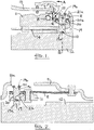
Figure 1 shows a radial section through part of a friction clutch in accordance with the present invention in an unworn clutch engaged position; -
Figure 2 shows a sectional view on line A-A ofFigure 1 ; -
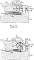
Figure 3 shows the embodiment ofFigure 1 with the clutch disengaged and about to make a wear adjustment; -
Figure 4 shows the embodiment ofFigure 1 with the clutch engaged after a wear adjustment has occurred, and -
Figures 5 and 6 show plan and edge views respectively of part of an adjuster ramp arrangement used in the adjuster of the present invention. - Referring to the drawings, a vehicle friction clutch 10 in accordance with the present invention has a
pressure plate 11 biased towards an associatedflywheel 12 by adiaphragm spring 13 supported from a clutch cover 9. Aclutch drive disc 14 is provided for clamping between thepressure plate 11 and theflywheel 12 and a ramptype wear adjuster 15 is located in the thrust path between thediaphragm spring 13 and thepressure plate 11 to compensate for wear of thedrive disc 14. Lift straps 8 (seeFigure 2 ) are provided at circumferentially spaced locations between the cover 9 and thepressure plate 11 to ensure that thepressure plate 11 lifts away from the flywheel when the clutch is disengaged. - The
wear adjuster 15 comprises a first ramp means in the form of aring 16 nearest to thepressure plate 11 and a second ramp means in the form of asecond ring 17 which is in contact with thefirst ring 16 but further away from the pressure plate and is also in contact with the diaphragm spring13. As can best be seen fromFigures 5 and 6 , the first andsecond rings coils springs 18 and therings ramp surfaces springs 18 to increase the combined effective thickness (see Y1 inFigure 1 ) of the rings to adjust the clutch for wear of thedisc 14 as will be explained below. - The wear adjuster also includes a wear sensor in the form of a
sensor pin 19 which extends through abore 20 in thepressure plate 11. A self-gripping washer 20a surrounds eachpin 19. The inner periphery of eachwasher 20a grips the associatedpin 19 to provide frictional resistance to the movement ofpin 19 inbore 20. Thewasher 20a is housed in arecess 23 in thepressure plate 11. The washer is held in its bore by thelift straps 8 which lie over the washer. - One end 19a of the
pin 19 engages theflywheel 12 when the clutch is engaged (seeFigure 1 ) and the pin is pushed through thebore 20 against the friction grip provided bywasher 20a as the friction disc wears14. The other end of thepin 19 has a head portion 19b which extends through ahole 21 a in an end portion of a hold downmember 21 and is riveted over at 19b to hold the end portion of the hold down member against a shoulder 19c on the pin which provides a first abutment. The hold downmember 21 is connected with or integrally formed with thesecond ramp ring 17. - In accordance with the present invention the hold down
member 21 is elastically deformable and operates as leaf lift spring. - In a typical construction there will be three
sensor pins 19 positioned at 120 degree intervals around thepressure plate 11 to provide a balance arrangement. Each sensor pin may conveniently be associated with arespective lift strap 8. Other numbers of sensor pins and lift straps can be employed if desired. - When the clutch is engaged by the
diaphragm spring 13 there is a solid metal thrust path fromdiaphragm spring 13 viaramp rings pressure plate 11. - As the
clutch disc 14 wears, thepins 19 are pushed through thebores 20 to load the elastic hold down memberleaf spring members 21 so that, after sufficient wear has occurred, when the clutch is released, the loading of the elastic hold downmembers 21 due to clutch disc wear, overcomes the effect of lift straps 8 (which tend to bias theramp rings ramp rings Figure 3 ). This gap is dependent on clutch disc wear and allows theadjuster springs 18 to rotate the two ramp rings relative to each other and thus increase the combined effective thickness of the ramp rings from Y1 inFigure 1 to Y2 inFigure 4. Figure 4 shows the adjusted clutch in the engaged condition immediately after a wear adjustment has been made when it can be seen that the distance Z of the diaphragm spring from the flywheel is the same as inFigure 1 so that the position and inclination (angle) of the diaphragm spring during operation of the clutch remains substantially constant as the clutch disc wears. - The use of an elastic hold down
member 21 removes the need for a separate spring means to separate theramp rings - As can be seen from the above the present invention provides a simple but effective wear adjuster mechanism for a vehicle clutch which is also reliable in operation.
Claims (6)
- A friction clutch (10) for a motor vehicle, the clutch comprising a pressure plate (11) biased towards an associated flywheel (12) by a diaphragm spring (13), a clutch drive disc (14) for clamping between the pressure plate and the associated flywheel, and a ramp type wear adjuster (15) located in the thrust path between the diaphragm spring and the pressure plate to compensate for wear of the drive disc, the wear adjuster comprising a first ramp means (16) nearest to the pressure plate and a second ramp means (17) in contact with the first ramp means but further away from the pressure plate, the first and second ramp means (16,17) being relatively rotatable about the axis of rotation of the pressure plate by an adjuster spring means (18) to increase the combined effective thickness (Y1) of the ramp means and hence maintain the travel of the diaphragm spring substantially constant as the clutch disc wears, the wear adjuster also including a wear sensor in the form of pin means (19) carried in bore means (20) in the pressure plate (11) and held relative to the pressure plate by a friction grip (20a), one end (19a) of the pin means (19) engaging the flywheel (12) when the clutch is engaged and the other end (19b, 19c) of the pin means contacting a hold down member (21) connected with the second ramp means (17), the pin means (19) being pushed through the bore means (20) towards the flywheel (12) as the clutch disc (14) wears, the clutch being characterised in that the hold down member (21) is elastically deformable on movement of the pin means (19) in the bore means (20) towards the flywheel, thus as the clutch disc (14) wears and the pin means is pushed through the bore means the elastic hold down member (21) is loaded so that, after sufficient wear has occurred, when the clutch is released, the loading of the elastic hold down member (21) due to clutch disc wear biases the ramp means (16,17) apart to allow a gap (X) to occur between the first and second ramp means (16,17) which is dependent on clutch disc wear, so that the adjuster spring means (18) can rotate the two ramp means relative to each other and thus increase the combined effective thickness (Y2) of the ramp means to maintain the position and inclination (angle) of the diaphragm spring (13) substantially constant as the clutch disc wears.
- A clutch according to claim 1 characterised in that the friction grip is provided by a self-griping washer (20a) carried on the pressure plate (11) whose inner periphery grips the pin means (19).
- A clutch according to any claim 1 or 2 characterised in that the other end of the pin means (19) has a head portion (19b) which extends through a hole (21 a) in an end portion of the hold down means (21) to hold the end portion of the hold down member against a shoulder (19c) on the pin.
- A clutch according to any one of claims 1 to 3 characterised by being provided with a plurality of wear sensors (15) at circumferentially spaced locations on the pressure plate (11).
- A clutch according to claim 1 or 4 characterised in that lift straps (8) act on the pressure plate (11) to lift the pressure plate away from the drive disc (14) when the clutch is released and the lift straps lie over the gripping washers (20a) to hold the washers in recesses (23) surrounding the bores (20) in the pressure plate.
- A clutch according to any one of claims 1 to 5 characterised in that the adjuster spring means comprises coil springs (18) which act circumferentially between the two ramp means (16,17).
Applications Claiming Priority (1)
| Application Number | Priority Date | Filing Date | Title |
|---|---|---|---|
| GBGB1522509.7A GB201522509D0 (en) | 2015-12-21 | 2015-12-21 | Vehicle clutches |
Publications (2)
| Publication Number | Publication Date |
|---|---|
| EP3184838A1 true EP3184838A1 (en) | 2017-06-28 |
| EP3184838B1 EP3184838B1 (en) | 2018-11-14 |
Family
ID=55311330
Family Applications (1)
| Application Number | Title | Priority Date | Filing Date |
|---|---|---|---|
| EP16002558.1A Not-in-force EP3184838B1 (en) | 2015-12-21 | 2016-12-01 | Vehicle clutches |
Country Status (2)
| Country | Link |
|---|---|
| EP (1) | EP3184838B1 (en) |
| GB (1) | GB201522509D0 (en) |
Cited By (1)
| Publication number | Priority date | Publication date | Assignee | Title |
|---|---|---|---|---|
| EP3809007A1 (en) | 2019-10-18 | 2021-04-21 | Raicam Driveline S.r.l. | Vehicle clutches |
Citations (3)
| Publication number | Priority date | Publication date | Assignee | Title |
|---|---|---|---|---|
| US5560463A (en) * | 1993-11-04 | 1996-10-01 | Fichtel & Sachs Ag | Friction clutch for a motor vehicle transmission and a friction clutch having automatic adjustment for wear |
| US5884741A (en) * | 1996-03-21 | 1999-03-23 | Fichtel & Sachs Ag | Friction clutch for a motor vehicle with wear adjustment |
| EP2778458A2 (en) * | 2013-03-11 | 2014-09-17 | AP Automotive Products Srl | Vehicle clutch including wear adjuster |
-
2015
- 2015-12-21 GB GBGB1522509.7A patent/GB201522509D0/en not_active Ceased
-
2016
- 2016-12-01 EP EP16002558.1A patent/EP3184838B1/en not_active Not-in-force
Patent Citations (3)
| Publication number | Priority date | Publication date | Assignee | Title |
|---|---|---|---|---|
| US5560463A (en) * | 1993-11-04 | 1996-10-01 | Fichtel & Sachs Ag | Friction clutch for a motor vehicle transmission and a friction clutch having automatic adjustment for wear |
| US5884741A (en) * | 1996-03-21 | 1999-03-23 | Fichtel & Sachs Ag | Friction clutch for a motor vehicle with wear adjustment |
| EP2778458A2 (en) * | 2013-03-11 | 2014-09-17 | AP Automotive Products Srl | Vehicle clutch including wear adjuster |
Cited By (1)
| Publication number | Priority date | Publication date | Assignee | Title |
|---|---|---|---|---|
| EP3809007A1 (en) | 2019-10-18 | 2021-04-21 | Raicam Driveline S.r.l. | Vehicle clutches |
Also Published As
| Publication number | Publication date |
|---|---|
| GB201522509D0 (en) | 2016-02-03 |
| EP3184838B1 (en) | 2018-11-14 |
Similar Documents
| Publication | Publication Date | Title |
|---|---|---|
| US5377803A (en) | Pressure plate arrangement for a motor vehicle friction clutch | |
| EP2174032B1 (en) | One-way clutch of sprag type | |
| JP5974450B2 (en) | Clutch device | |
| US11173889B2 (en) | Disc brake assembly | |
| US20190353210A1 (en) | Transmission clutch including locking torsion spring | |
| EP0020056A2 (en) | Improvements in or relating to twin plate friction clutches | |
| EP3184838B1 (en) | Vehicle clutches | |
| JP2019504246A (en) | Coupling assembly having overrun mode and grooved locking member for use in coupling assembly | |
| CN106536958A (en) | clutch disc | |
| KR100419587B1 (en) | Stopless self adjusting diaphragm clutch | |
| JP7143400B2 (en) | Centrifugal wedge clutch | |
| JP2022082771A (en) | One-way clutch | |
| EP2778458B1 (en) | Vehicle clutch including wear adjuster | |
| JP3943950B2 (en) | Clutch cover assembly | |
| US5947251A (en) | Shim plate for remanufactured clutch release bearing and housing assembly | |
| US9453539B2 (en) | Clutch cover assembly | |
| US6325193B1 (en) | Friction clutch with an adjustment limiting device | |
| US8997963B2 (en) | Cam hard stop for end of life | |
| EP3809007A1 (en) | Vehicle clutches | |
| JP2017082971A (en) | Pulley device | |
| JP2004301191A (en) | Vehicle friction clutch | |
| US20120067687A1 (en) | Pivot ring for a manual clutch | |
| JP2021089017A (en) | Clutch device | |
| US11441615B2 (en) | Clutch adjustment system with wear resistant features for back driving prevention | |
| CN104514819A (en) | One-way mechanical clutch system and alternator comprising such a system |
Legal Events
| Date | Code | Title | Description |
|---|---|---|---|
| PUAI | Public reference made under article 153(3) epc to a published international application that has entered the european phase |
Free format text: ORIGINAL CODE: 0009012 |
|
| AK | Designated contracting states |
Kind code of ref document: A1 Designated state(s): AL AT BE BG CH CY CZ DE DK EE ES FI FR GB GR HR HU IE IS IT LI LT LU LV MC MK MT NL NO PL PT RO RS SE SI SK SM TR |
|
| AX | Request for extension of the european patent |
Extension state: BA ME |
|
| 17P | Request for examination filed |
Effective date: 20180102 |
|
| RBV | Designated contracting states (corrected) |
Designated state(s): AL AT BE BG CH CY CZ DE DK EE ES FI FR GB GR HR HU IE IS IT LI LT LU LV MC MK MT NL NO PL PT RO RS SE SI SK SM TR |
|
| GRAP | Despatch of communication of intention to grant a patent |
Free format text: ORIGINAL CODE: EPIDOSNIGR1 |
|
| RIC1 | Information provided on ipc code assigned before grant |
Ipc: F16D 13/75 20060101AFI20180514BHEP |
|
| INTG | Intention to grant announced |
Effective date: 20180605 |
|
| GRAS | Grant fee paid |
Free format text: ORIGINAL CODE: EPIDOSNIGR3 |
|
| GRAA | (expected) grant |
Free format text: ORIGINAL CODE: 0009210 |
|
| AK | Designated contracting states |
Kind code of ref document: B1 Designated state(s): AL AT BE BG CH CY CZ DE DK EE ES FI FR GB GR HR HU IE IS IT LI LT LU LV MC MK MT NL NO PL PT RO RS SE SI SK SM TR |
|
| REG | Reference to a national code |
Ref country code: CH Ref legal event code: EP Ref country code: AT Ref legal event code: REF Ref document number: 1065194 Country of ref document: AT Kind code of ref document: T Effective date: 20181115 |
|
| REG | Reference to a national code |
Ref country code: DE Ref legal event code: R096 Ref document number: 602016007029 Country of ref document: DE |
|
| REG | Reference to a national code |
Ref country code: IE Ref legal event code: FG4D |
|
| REG | Reference to a national code |
Ref country code: NL Ref legal event code: MP Effective date: 20181114 |
|
| REG | Reference to a national code |
Ref country code: LT Ref legal event code: MG4D |
|
| REG | Reference to a national code |
Ref country code: AT Ref legal event code: MK05 Ref document number: 1065194 Country of ref document: AT Kind code of ref document: T Effective date: 20181114 |
|
| PG25 | Lapsed in a contracting state [announced via postgrant information from national office to epo] |
Ref country code: BG Free format text: LAPSE BECAUSE OF FAILURE TO SUBMIT A TRANSLATION OF THE DESCRIPTION OR TO PAY THE FEE WITHIN THE PRESCRIBED TIME-LIMIT Effective date: 20190214 Ref country code: LT Free format text: LAPSE BECAUSE OF FAILURE TO SUBMIT A TRANSLATION OF THE DESCRIPTION OR TO PAY THE FEE WITHIN THE PRESCRIBED TIME-LIMIT Effective date: 20181114 Ref country code: FI Free format text: LAPSE BECAUSE OF FAILURE TO SUBMIT A TRANSLATION OF THE DESCRIPTION OR TO PAY THE FEE WITHIN THE PRESCRIBED TIME-LIMIT Effective date: 20181114 Ref country code: AT Free format text: LAPSE BECAUSE OF FAILURE TO SUBMIT A TRANSLATION OF THE DESCRIPTION OR TO PAY THE FEE WITHIN THE PRESCRIBED TIME-LIMIT Effective date: 20181114 Ref country code: IS Free format text: LAPSE BECAUSE OF FAILURE TO SUBMIT A TRANSLATION OF THE DESCRIPTION OR TO PAY THE FEE WITHIN THE PRESCRIBED TIME-LIMIT Effective date: 20190314 Ref country code: NO Free format text: LAPSE BECAUSE OF FAILURE TO SUBMIT A TRANSLATION OF THE DESCRIPTION OR TO PAY THE FEE WITHIN THE PRESCRIBED TIME-LIMIT Effective date: 20190214 Ref country code: ES Free format text: LAPSE BECAUSE OF FAILURE TO SUBMIT A TRANSLATION OF THE DESCRIPTION OR TO PAY THE FEE WITHIN THE PRESCRIBED TIME-LIMIT Effective date: 20181114 Ref country code: HR Free format text: LAPSE BECAUSE OF FAILURE TO SUBMIT A TRANSLATION OF THE DESCRIPTION OR TO PAY THE FEE WITHIN THE PRESCRIBED TIME-LIMIT Effective date: 20181114 Ref country code: LV Free format text: LAPSE BECAUSE OF FAILURE TO SUBMIT A TRANSLATION OF THE DESCRIPTION OR TO PAY THE FEE WITHIN THE PRESCRIBED TIME-LIMIT Effective date: 20181114 |
|
| PG25 | Lapsed in a contracting state [announced via postgrant information from national office to epo] |
Ref country code: AL Free format text: LAPSE BECAUSE OF FAILURE TO SUBMIT A TRANSLATION OF THE DESCRIPTION OR TO PAY THE FEE WITHIN THE PRESCRIBED TIME-LIMIT Effective date: 20181114 Ref country code: SE Free format text: LAPSE BECAUSE OF FAILURE TO SUBMIT A TRANSLATION OF THE DESCRIPTION OR TO PAY THE FEE WITHIN THE PRESCRIBED TIME-LIMIT Effective date: 20181114 Ref country code: NL Free format text: LAPSE BECAUSE OF FAILURE TO SUBMIT A TRANSLATION OF THE DESCRIPTION OR TO PAY THE FEE WITHIN THE PRESCRIBED TIME-LIMIT Effective date: 20181114 Ref country code: RS Free format text: LAPSE BECAUSE OF FAILURE TO SUBMIT A TRANSLATION OF THE DESCRIPTION OR TO PAY THE FEE WITHIN THE PRESCRIBED TIME-LIMIT Effective date: 20181114 Ref country code: PT Free format text: LAPSE BECAUSE OF FAILURE TO SUBMIT A TRANSLATION OF THE DESCRIPTION OR TO PAY THE FEE WITHIN THE PRESCRIBED TIME-LIMIT Effective date: 20190314 Ref country code: GR Free format text: LAPSE BECAUSE OF FAILURE TO SUBMIT A TRANSLATION OF THE DESCRIPTION OR TO PAY THE FEE WITHIN THE PRESCRIBED TIME-LIMIT Effective date: 20190215 |
|
| PG25 | Lapsed in a contracting state [announced via postgrant information from national office to epo] |
Ref country code: PL Free format text: LAPSE BECAUSE OF FAILURE TO SUBMIT A TRANSLATION OF THE DESCRIPTION OR TO PAY THE FEE WITHIN THE PRESCRIBED TIME-LIMIT Effective date: 20181114 Ref country code: DK Free format text: LAPSE BECAUSE OF FAILURE TO SUBMIT A TRANSLATION OF THE DESCRIPTION OR TO PAY THE FEE WITHIN THE PRESCRIBED TIME-LIMIT Effective date: 20181114 Ref country code: CZ Free format text: LAPSE BECAUSE OF FAILURE TO SUBMIT A TRANSLATION OF THE DESCRIPTION OR TO PAY THE FEE WITHIN THE PRESCRIBED TIME-LIMIT Effective date: 20181114 |
|
| REG | Reference to a national code |
Ref country code: DE Ref legal event code: R097 Ref document number: 602016007029 Country of ref document: DE |
|
| PG25 | Lapsed in a contracting state [announced via postgrant information from national office to epo] |
Ref country code: EE Free format text: LAPSE BECAUSE OF FAILURE TO SUBMIT A TRANSLATION OF THE DESCRIPTION OR TO PAY THE FEE WITHIN THE PRESCRIBED TIME-LIMIT Effective date: 20181114 Ref country code: RO Free format text: LAPSE BECAUSE OF FAILURE TO SUBMIT A TRANSLATION OF THE DESCRIPTION OR TO PAY THE FEE WITHIN THE PRESCRIBED TIME-LIMIT Effective date: 20181114 Ref country code: SM Free format text: LAPSE BECAUSE OF FAILURE TO SUBMIT A TRANSLATION OF THE DESCRIPTION OR TO PAY THE FEE WITHIN THE PRESCRIBED TIME-LIMIT Effective date: 20181114 Ref country code: LU Free format text: LAPSE BECAUSE OF NON-PAYMENT OF DUE FEES Effective date: 20181201 Ref country code: MC Free format text: LAPSE BECAUSE OF FAILURE TO SUBMIT A TRANSLATION OF THE DESCRIPTION OR TO PAY THE FEE WITHIN THE PRESCRIBED TIME-LIMIT Effective date: 20181114 Ref country code: SK Free format text: LAPSE BECAUSE OF FAILURE TO SUBMIT A TRANSLATION OF THE DESCRIPTION OR TO PAY THE FEE WITHIN THE PRESCRIBED TIME-LIMIT Effective date: 20181114 |
|
| REG | Reference to a national code |
Ref country code: IE Ref legal event code: MM4A |
|
| PLBE | No opposition filed within time limit |
Free format text: ORIGINAL CODE: 0009261 |
|
| STAA | Information on the status of an ep patent application or granted ep patent |
Free format text: STATUS: NO OPPOSITION FILED WITHIN TIME LIMIT |
|
| REG | Reference to a national code |
Ref country code: BE Ref legal event code: MM Effective date: 20181231 |
|
| 26N | No opposition filed |
Effective date: 20190815 |
|
| PG25 | Lapsed in a contracting state [announced via postgrant information from national office to epo] |
Ref country code: FR Free format text: LAPSE BECAUSE OF NON-PAYMENT OF DUE FEES Effective date: 20190114 Ref country code: IE Free format text: LAPSE BECAUSE OF NON-PAYMENT OF DUE FEES Effective date: 20181201 Ref country code: SI Free format text: LAPSE BECAUSE OF FAILURE TO SUBMIT A TRANSLATION OF THE DESCRIPTION OR TO PAY THE FEE WITHIN THE PRESCRIBED TIME-LIMIT Effective date: 20181114 |
|
| PG25 | Lapsed in a contracting state [announced via postgrant information from national office to epo] |
Ref country code: BE Free format text: LAPSE BECAUSE OF NON-PAYMENT OF DUE FEES Effective date: 20181231 |
|
| PG25 | Lapsed in a contracting state [announced via postgrant information from national office to epo] |
Ref country code: MT Free format text: LAPSE BECAUSE OF NON-PAYMENT OF DUE FEES Effective date: 20181201 |
|
| PG25 | Lapsed in a contracting state [announced via postgrant information from national office to epo] |
Ref country code: TR Free format text: LAPSE BECAUSE OF FAILURE TO SUBMIT A TRANSLATION OF THE DESCRIPTION OR TO PAY THE FEE WITHIN THE PRESCRIBED TIME-LIMIT Effective date: 20181114 |
|
| PG25 | Lapsed in a contracting state [announced via postgrant information from national office to epo] |
Ref country code: MK Free format text: LAPSE BECAUSE OF NON-PAYMENT OF DUE FEES Effective date: 20181114 Ref country code: HU Free format text: LAPSE BECAUSE OF FAILURE TO SUBMIT A TRANSLATION OF THE DESCRIPTION OR TO PAY THE FEE WITHIN THE PRESCRIBED TIME-LIMIT; INVALID AB INITIO Effective date: 20161201 Ref country code: CY Free format text: LAPSE BECAUSE OF FAILURE TO SUBMIT A TRANSLATION OF THE DESCRIPTION OR TO PAY THE FEE WITHIN THE PRESCRIBED TIME-LIMIT Effective date: 20181114 |
|
| REG | Reference to a national code |
Ref country code: CH Ref legal event code: PL |
|
| PG25 | Lapsed in a contracting state [announced via postgrant information from national office to epo] |
Ref country code: CH Free format text: LAPSE BECAUSE OF NON-PAYMENT OF DUE FEES Effective date: 20191231 Ref country code: LI Free format text: LAPSE BECAUSE OF NON-PAYMENT OF DUE FEES Effective date: 20191231 |
|
| REG | Reference to a national code |
Ref country code: DE Ref legal event code: R082 Ref document number: 602016007029 Country of ref document: DE Representative=s name: FRIESE GOEDEN PATENTANWAELTE PARTGMBB, DE Ref country code: DE Ref legal event code: R081 Ref document number: 602016007029 Country of ref document: DE Owner name: RAICAM DRIVELINE S.R.L., IT Free format text: FORMER OWNER: AP AUTOMOTIVE PRODUCTS SRL, MOIE DI MAIOLATI SPONTINI, ANCONA, IT |
|
| PGFP | Annual fee paid to national office [announced via postgrant information from national office to epo] |
Ref country code: GB Payment date: 20211222 Year of fee payment: 6 Ref country code: DE Payment date: 20211210 Year of fee payment: 6 |
|
| PGFP | Annual fee paid to national office [announced via postgrant information from national office to epo] |
Ref country code: IT Payment date: 20211222 Year of fee payment: 6 |
|
| REG | Reference to a national code |
Ref country code: DE Ref legal event code: R119 Ref document number: 602016007029 Country of ref document: DE |
|
| GBPC | Gb: european patent ceased through non-payment of renewal fee |
Effective date: 20221201 |
|
| PG25 | Lapsed in a contracting state [announced via postgrant information from national office to epo] |
Ref country code: GB Free format text: LAPSE BECAUSE OF NON-PAYMENT OF DUE FEES Effective date: 20221201 Ref country code: DE Free format text: LAPSE BECAUSE OF NON-PAYMENT OF DUE FEES Effective date: 20230701 |
|
| PG25 | Lapsed in a contracting state [announced via postgrant information from national office to epo] |
Ref country code: IT Free format text: LAPSE BECAUSE OF NON-PAYMENT OF DUE FEES Effective date: 20221201 |