EP3184793A1 - Long injector for fuel injection into an internal combustion engine - Google Patents
Long injector for fuel injection into an internal combustion engine Download PDFInfo
- Publication number
- EP3184793A1 EP3184793A1 EP15201777.8A EP15201777A EP3184793A1 EP 3184793 A1 EP3184793 A1 EP 3184793A1 EP 15201777 A EP15201777 A EP 15201777A EP 3184793 A1 EP3184793 A1 EP 3184793A1
- Authority
- EP
- European Patent Office
- Prior art keywords
- base portion
- extension portion
- conductive terminal
- electrically conductive
- electrical contacts
- Prior art date
- Legal status (The legal status is an assumption and is not a legal conclusion. Google has not performed a legal analysis and makes no representation as to the accuracy of the status listed.)
- Withdrawn
Links
Images


Classifications
-
- F—MECHANICAL ENGINEERING; LIGHTING; HEATING; WEAPONS; BLASTING
- F02—COMBUSTION ENGINES; HOT-GAS OR COMBUSTION-PRODUCT ENGINE PLANTS
- F02M—SUPPLYING COMBUSTION ENGINES IN GENERAL WITH COMBUSTIBLE MIXTURES OR CONSTITUENTS THEREOF
- F02M51/00—Fuel-injection apparatus characterised by being operated electrically
- F02M51/005—Arrangement of electrical wires and connections, e.g. wire harness, sockets, plugs; Arrangement of electronic control circuits in or on fuel injection apparatus
-
- F—MECHANICAL ENGINEERING; LIGHTING; HEATING; WEAPONS; BLASTING
- F02—COMBUSTION ENGINES; HOT-GAS OR COMBUSTION-PRODUCT ENGINE PLANTS
- F02M—SUPPLYING COMBUSTION ENGINES IN GENERAL WITH COMBUSTIBLE MIXTURES OR CONSTITUENTS THEREOF
- F02M69/00—Low-pressure fuel-injection apparatus ; Apparatus with both continuous and intermittent injection; Apparatus injecting different types of fuel
- F02M69/46—Details, component parts or accessories not provided for in, or of interest apart from, the apparatus covered by groups F02M69/02 - F02M69/44
- F02M69/462—Arrangement of fuel conduits, e.g. with valves for maintaining pressure in the pipes after the engine being shut-down
- F02M69/465—Arrangement of fuel conduits, e.g. with valves for maintaining pressure in the pipes after the engine being shut-down of fuel rails
-
- F—MECHANICAL ENGINEERING; LIGHTING; HEATING; WEAPONS; BLASTING
- F02—COMBUSTION ENGINES; HOT-GAS OR COMBUSTION-PRODUCT ENGINE PLANTS
- F02M—SUPPLYING COMBUSTION ENGINES IN GENERAL WITH COMBUSTIBLE MIXTURES OR CONSTITUENTS THEREOF
- F02M2200/00—Details of fuel-injection apparatus, not otherwise provided for
- F02M2200/80—Fuel injection apparatus manufacture, repair or assembly
- F02M2200/8023—Fuel injection apparatus manufacture, repair or assembly the assembly involving use of quick-acting mechanisms, e.g. clips
-
- F—MECHANICAL ENGINEERING; LIGHTING; HEATING; WEAPONS; BLASTING
- F02—COMBUSTION ENGINES; HOT-GAS OR COMBUSTION-PRODUCT ENGINE PLANTS
- F02M—SUPPLYING COMBUSTION ENGINES IN GENERAL WITH COMBUSTIBLE MIXTURES OR CONSTITUENTS THEREOF
- F02M2200/00—Details of fuel-injection apparatus, not otherwise provided for
- F02M2200/85—Mounting of fuel injection apparatus
- F02M2200/853—Mounting of fuel injection apparatus involving use of quick-acting mechanism, e.g. clips
Definitions
- the present invention relates to a long injector for fuel injection into an internal combustion engine, and in particular to an electrical connection between a base portion and an extension portion of a long injector, wherein the long injector is formed by connecting the extension portion to the base portion.
- fuel injector systems are used to inject highly pressurized gasoline directly into combustion chambers of the internal combustion engines.
- an injector for fuel injection must be inserted deep into an internal combustion chamber of an internal combustion engine, in order to improve the efficiency of the engine.
- Such a fuel injector in common internal combustion engines typically has a length of about 90 mm. Due to the restricted space in the cylindrical volume inside the cylinder block and densely arranged equipment around the cylinder head, which also limits the space available outside the cylinder block, long injectors have been designed by connecting an extension portion to such a common fuel injector. In particular, by connecting an extension portion to a common fuel injector, the length of the fuel injector can be extended from about 90 mm to a length ranging from about 150 mm to about 190 mm.
- the document US 7,213,578 B2 discloses a mounting structure for an injector for fuel injection into an internal combustion engine, wherein a fixing member is inserted into a hole of a cylinder head in an axial direction. Thus, the injector is fixed between the fixing member and the cylinder head. A connector portion of the fixing member is inserted into the hole of the cylinder head together with the fixing member, and the connector portion of the fixing member is connected to a connector portion of the injector. A first socket provided on an end of the connector portion of the fixing member opposite from the injector is disposed outside the cylinder head, wherein this socket is connected to a power source.
- a long injector for fuel injection into an internal combustion engine.
- the long injector comprises a base portion and an extension portion.
- a "long injector” is in particular understood to be an injector with a base portion and an extension portion, longitudinally extending the base portion.
- the extension portion is electrically connected to the base portion, wherein an end of the extension portion comprises an electrically conductive terminal with one or more contact clips, wherein the one or more contact clips are spaced at a distance from each other or from a side wall of the electrically conductive terminal, wherein an end of the base portion comprises one or more electrical contacts, wherein each of the one or more electrical contacts is positioned at the end of the base portion in such a way, that each of the one or more electrical contacts can slide into a respective contact clip of the electrically conductive terminal when connecting the extension portion to the base
- the electrically conductive terminal has a latch mechanism, wherein an electrical connection between the base portion and the extension portion is created, when each of the one or more electrical contacts is inserted into the respective contact clip and held by the latch mechanism.
- an improved long injector which can easily be inserted deeply into an internal combustion engine.
- the one or more electrical contacts on the base portion and the respective contact clips on the electrically conductive terminal are located and orientated in such a way, that their outline, when they are connected to each other, lies within the cylindrical shape of the long injector.
- the extension portion can be fixed onto the cylinder head and acts as a mechanical fixture of the base portion of the long injector.
- the latch mechanism of the electrical connection provides a mechanical stop during the assembly process of the extension portion to the base portion and stabilizes the assembly mechanically in such a way, that a stable electrical connection between the extension portion and the base portion is maintained.
- the long injector can further comprise an encapsulation body which encapsulates the electrical connection.
- the encapsulation body provides a one-body design of the long injector and mechanically protects the electrical connection, wherein additionally the electrical connection is protected against ingress of solid objects and liquids in order to prevent corrosion that could lead to a destruction of the electrical connection.
- the one or more contact clips can comprise an elastic material, wherein the latch mechanism is realized by the elastic material in such a way, that the one or more electric contacts are compressed by the elastic material of the one or more contact clips.
- the latch mechanism can be realized by the design of the contact clips, and thus by fewer components compared to a design, wherein the latch mechanism is realized by separate components within the electrically conductive terminal. Thereby material cost and process time of the assembly of the extension portion and the base portion can be reduced, whereby the overall costs of the long injector are reduced.
- the end of the base portion may comprise one or more ribs that are positioned in such a way, that each of the one or more ribs can be inserted into a respective distance between two contact clips of the electrically conductive terminal or a respective distance between a contact clip and a side wall of the electrically conductive terminal.
- the one or more contact clips can be stabilized during insertion of the electrical contacts and stably kept in the position, in which the electrical connection is created, and prevented from losing the electrical connection by expanding. This is also important during encapsulating the electrical connection, as the encapsulation material is injected with pressure and heat onto the electrical connection, in particular the electrical connection that is formed by the electrical contacts and the contact clips.
- a fuel injection system of an internal combustion engine which comprises a long injector as described above.
- the advantage of such a fuel injection system is that it comprises a long injector that can easily be inserted deeply into an internal combustion chamber of an internal combustion engine, wherein the extension portion is fixed onto the cylinder head and acts as a mechanical fixture for the base portion of the injector and wherein the electrical connection from the top of the extension portion to the base portion is realized in such a way, that it does not protrude out of the cylindrical shape of the long injector.
- a vehicle which comprises a fuel injection system that comprises a long injector as described above.
- the advantage of such a vehicle is that the long injector can easily be inserted deeply into an internal combustion chamber of an internal combustion engine, wherein the extension portion is fixed onto the cylinder head and acts as a mechanical fixture for the base portion of the injector and wherein the electrical connection from the top of the extension portion to the base portion is realized in such a way, that it does not protrude out of the cylindrical shape of the long injector.
- a method for electrically connecting a base portion to an extension portion to produce a long injector for fuel injection into an internal combustion engine, wherein the method comprises the following steps: Providing an extension portion, wherein an end of the extension portion comprises an electrically conductive terminal with one or more contact clips, wherein the one or more contact clips are spaced at a distance from each other or from a side wall of the electrically conductive terminal, providing a base portion, wherein an end of the base portion comprises one or more electrical contacts, wherein each of the one or more electrical contacts is positioned at the end of the base portion in such a way, that each of the one or more electrical contacts can slide into a respective contact clip of the electrically conductive terminal when connecting the extension portion to the base portion, electrically connecting the extension portion to
- the base portion by inserting the one or more electrical contacts into the respective contact clips, until each of the one or more electrical contacts is held by a latch mechanism of the electrically conductive terminal.
- an extension portion comprising an electrically conductive terminal, which comprises one or more contact clips and a base portion, comprising one or more electrical contacts, wherein the one or more electrical contacts on the base portion and the respective contact clips on the electrically conductive terminal are located and orientated in such a way, that it can be ensured that the electrical connection between the base portion and the extension portion does not protrude out of the cylindrical shape of the long injector.
- the long injector can be inserted deeply into the cylindrical opening of the cylinder block of the engine.
- the method may further comprise the step of encapsulating the electrical connection.
- an encapsulation body is provided, through which a one-body design of the long injector can be provided, which mechanically protects the electrical connection, wherein additionally the electrical connection is protected against ingress of solid objects and liquids in order to prevent corrosion that could lead to a destruction of the electrical connection.
- the one or more contact clips can comprise an elastic material
- the step of electrically connecting the extension portion to the base portion comprises compressing the one or more electric contacts by the elastic material of the one or more contact clips.
- the latch mechanism can be realized by the design of the contact clips, and thus by fewer components compared to a design, wherein the latch mechanism is realized by separate components within the electrically conductive terminal. Thereby material cost and process time of the assembly of the extension portion and the base portion can be reduced, whereby the overall costs of the long injector are reduced.
- the method may further comprise the step of providing one or more ribs on the end of the base portion that are positioned in such a way, that each of the one or more ribs can be inserted into a respective distance between two contact clips of the electrically conductive terminal or a respective distance between a contact clip and a side wall of the electrically conductive terminal.
- the one or more contact clips can be stabilized during insertion of the electrical contacts and stably kept in the position in which the electrical connection is created and prevented from losing the electrical connection by expanding.
- Figure 1 illustrates a schematic drawing of a long injector 1 for fuel injection into an internal combustion engine, according to embodiments of the present invention.
- an injector for fuel injection must be inserted deep into the internal combustion chamber in order to improve the efficiency of the engines. Due to the restricted space inside the cylinder block and the densely arranged equipment around the cylinder head, which limits the space available outside the cylinder block, long injectors have been developed to insert the injector deeply into the cylinder head of internal combustion chambers. In particular by adding an extension portion to a base portion of an injector a long injector with a length in the range of about 150 mm to about 190 mm is provided.
- the long injector 1 comprises a base portion 2 and an extension portion 3, wherein an end 9 of the base portion 2 is connected mechanically and electrically to an end 4 of the extension portion 3.
- An electrical connection 12 is realized from the end 9 of the base portion 2 to the top of the extension portion 3, where an external power source can be connected to the injector with a connector device by using a standard plug connector.
- Figure 2a illustrates a schematic drawing of the electrical connection 12 between the extension portion 3 and the base portion 2 of a long injector 1 before encapsulating the electrical connection, according to embodiments of the present invention.
- the base portion 2 comprises an end 9 facing to the extension portion 3 of the long injector 1, on which two electrical contacts 10 are provided.
- the extension portion 3 comprises an end 4 facing the base portion 2, on which an electrically conductive terminal 5 with two contact clips 6 is provided.
- the contact clips 6 are spaced at a distance 7 from each other and from a side wall 8 of the electrically conductive terminal 5, and thus, the contact clips 6 are provided in a fork design. Therein the contact clips 6 are positioned and orientated in such a way, that they do not protrude out of the cylindrical shape of the injector.
- the two electrical contacts 10 are positioned relative to the respective contact clips 6 in such a way, that each of two electrical contacts 10 can slide into a respective contact clip 5 of the electrically conductive terminal 5 when connecting the extension portion 3 to the base portion 2.
- the electronically conductive terminal 5 of the extension portion 3 has a latch mechanism 11. Therein, an electrical connection 12 is created, when each of the two electrical contacts 10 is inserted into the respective contact clip 5 and held by the latch mechanism 11.
- the electrical connection between the base portion and the extension portion does not protrude out of the cylindrical shape of the long injector and the long injector can be inserted deeply into the cylindrical opening of the cylinder block of the engine and thus, an improved long injector is provided, which can easily be inserted deeply into an internal combustion engine.
- the two contact clips 6 comprise an elastic material 14, wherein the latch mechanism 11 is realized by the elastic material 14 of the contact clips 6 in such a way, that the two electric contacts 10 are compressed by the elastic material 14 of the two contact clips 6.
- the latch mechanism 11 is realized by the elastic material 14 of the contact clips 6 should merely be understood as an example, and the latch mechanism 11 can also be realized by a plurality of other components, for example by a mechanical latch mechanism.
- the end 9 of the base portion 2 further comprises three ribs 15 that are positioned in such a way, that each rib 14 can be inserted into a distance 7 between two contact clips 6 of the extension portion 3 or a distance 7 between a contact clip 6 and a side wall 8 of the electrically conductive terminal 5.
- the ribs can be formed by plastic material within the base portion 2.
- Figure 2b illustrates a schematic drawing of the electrical connection 12 between the extension portion 3 and the base portion 2 of a long injector 1 after encapsulating the electrical connection, according to embodiments of the present invention.
- the encapsulation body 13 formed by encapsulating of the electrical connection encloses the end 9 of the base portion 2 that is attached to the end 4 of extension portion 3 by the electrical connection 12, wherein the body can consist of a resin material or a thermo-plastic material used in an overmolding process.
- the design realizes a single body for the injector, wherein both portions are mechanically connected in a stable way by the encapsulation body 13 that can only be dismantled with destruction.
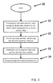
- Figure 3 is a flow chart illustrating a method for electrically connecting a base portion 2 to an extension portion 3 to produce a long injector 1 for fuel injection into an internal combustion engine, according to embodiments of the present invention.
- step 21 an extension portion is provided, wherein an end of the extension portion comprises an electrically conductive terminal with one or more contact clips, wherein the one or more contact clips are spaced at a distance from each other or from a side wall of the electrically conductive terminal.
- a base portion is provided, wherein an end of the base portion comprises one or more electrical contacts, wherein each of the one or more electrical contacts is positioned in such a way, that each of the one or more electrical contacts can slide into a respective contact clip of the extension terminal when connecting the extension portion to the base portion.
- step 23 the extension portion is electrically connected to the base portion, by inserting the one or more electrical contacts into the respective contact clip until each of the one or more electrical contacts is held by a latch mechanism of the electronically conductive terminal.
- the electrical connection is created, when each of the one or more electrical contacts is inserted into the respective contact clip and held by the latch mechanism.
- the method shown in Fig. 3 comprises the additional step 24 of encapsulating the electrical connection with an encapsulation body.
- Encapsulating the electrical connection can be an overmolding process with a resin or thermo-plastic material.
Landscapes
- Engineering & Computer Science (AREA)
- Chemical & Material Sciences (AREA)
- Combustion & Propulsion (AREA)
- Mechanical Engineering (AREA)
- General Engineering & Computer Science (AREA)
- Fuel-Injection Apparatus (AREA)
Abstract
Long injector for fuel injection into an internal combustion engine, which comprises a base portion (2) and an extension portion (3), wherein the extension portion (3) is electrically connected to the base portion (2), wherein an end (4) of the extension portion (3) comprises an electrically conductive terminal (5) with one or more contact clips (6), wherein the one or more contact clips (6) are spaced at a distance (7) from each other or from a side wall (8) of the electrically conductive terminal (5), wherein an end (9) of the base portion (2) comprises one or more electrical contacts (10), wherein each of the one or more electrical contacts (10) is positioned at the end (9) of the base portion (2) in such a way, that each of the one or more electrical contacts (10) can slide into a respective contact clip (5) of the electrically conductive terminal (5) when connecting the extension portion (3) to the base portion (2), and wherein the electrically conductive terminal (5) has a latch mechanism (11), wherein an electrical connection (12) between the base portion (2) and the extension portion (3) is created, when each of the one or more electrical contacts (10) is inserted into the respective contact clip (5) and held by the latch mechanism (11) .
Description
- The present invention relates to a long injector for fuel injection into an internal combustion engine, and in particular to an electrical connection between a base portion and an extension portion of a long injector, wherein the long injector is formed by connecting the extension portion to the base portion.
- In common internal combustion engines, fuel injector systems are used to inject highly pressurized gasoline directly into combustion chambers of the internal combustion engines. Therein an injector for fuel injection must be inserted deep into an internal combustion chamber of an internal combustion engine, in order to improve the efficiency of the engine. Such a fuel injector in common internal combustion engines typically has a length of about 90 mm. Due to the restricted space in the cylindrical volume inside the cylinder block and densely arranged equipment around the cylinder head, which also limits the space available outside the cylinder block, long injectors have been designed by connecting an extension portion to such a common fuel injector. In particular, by connecting an extension portion to a common fuel injector, the length of the fuel injector can be extended from about 90 mm to a length ranging from about 150 mm to about 190 mm.
- The document
US 7,213,578 B2 discloses a mounting structure for an injector for fuel injection into an internal combustion engine, wherein a fixing member is inserted into a hole of a cylinder head in an axial direction. Thus, the injector is fixed between the fixing member and the cylinder head. A connector portion of the fixing member is inserted into the hole of the cylinder head together with the fixing member, and the connector portion of the fixing member is connected to a connector portion of the injector. A first socket provided on an end of the connector portion of the fixing member opposite from the injector is disposed outside the cylinder head, wherein this socket is connected to a power source. - It is an object of the present invention to provide an improved long injector, which can easily be inserted deeply into an internal combustion engine.
- This object is solved by the subject matter of the independent claims. Further advantageous features are subject matter of the dependent claims.
- According to an embodiment of the invention, this object is solved by a long injector for fuel injection into an internal combustion engine. The long injector comprises a base portion and an extension portion. In the present context, a "long injector" is in particular understood to be an injector with a base portion and an extension portion, longitudinally extending the base portion.
- The extension portion is electrically connected to the base portion, wherein an end of the extension portion comprises an electrically conductive terminal with one or more contact clips, wherein the one or more contact clips are spaced at a distance from each other or from a side wall of the electrically conductive terminal, wherein an end of the base portion comprises one or more electrical contacts, wherein each of the one or more electrical contacts is positioned at the end of the base portion in such a way, that each of the one or more electrical contacts can slide into a respective contact clip of the electrically conductive terminal when connecting the extension portion to the base
- portion, and wherein the electrically conductive terminal has a latch mechanism, wherein an electrical connection between the base portion and the extension portion is created, when each of the one or more electrical contacts is inserted into the respective contact clip and held by the latch mechanism.
- Thereby, an improved long injector is provided, which can easily be inserted deeply into an internal combustion engine. In particular the one or more electrical contacts on the base portion and the respective contact clips on the electrically conductive terminal are located and orientated in such a way, that their outline, when they are connected to each other, lies within the cylindrical shape of the long injector. Thus, it can be ensured that the electrical connection between the base portion and the extension portion does not protrude out of the cylindrical shape of the long injector and the long injector can be inserted deeply into the cylindrical opening of the cylinder block of the engine. Therein the extension portion can be fixed onto the cylinder head and acts as a mechanical fixture of the base portion of the long injector. The latch mechanism of the electrical connection provides a mechanical stop during the assembly process of the extension portion to the base portion and stabilizes the assembly mechanically in such a way, that a stable electrical connection between the extension portion and the base portion is maintained.
- Therein the long injector can further comprise an encapsulation body which encapsulates the electrical connection. The encapsulation body provides a one-body design of the long injector and mechanically protects the electrical connection, wherein additionally the electrical connection is protected against ingress of solid objects and liquids in order to prevent corrosion that could lead to a destruction of the electrical connection. Further the one or more contact clips can comprise an elastic material, wherein the latch mechanism is realized by the elastic material in such a way, that the one or more electric contacts are compressed by the elastic material of the one or more contact clips. Thus, the latch mechanism can be realized by the design of the contact clips, and thus by fewer components compared to a design, wherein the latch mechanism is realized by separate components within the electrically conductive terminal. Thereby material cost and process time of the assembly of the extension portion and the base portion can be reduced, whereby the overall costs of the long injector are reduced.
- Further the end of the base portion may comprise one or more ribs that are positioned in such a way, that each of the one or more ribs can be inserted into a respective distance between two contact clips of the electrically conductive terminal or a respective distance between a contact clip and a side wall of the electrically conductive terminal. By the ribs the one or more contact clips can be stabilized during insertion of the electrical contacts and stably kept in the position, in which the electrical connection is created, and prevented from losing the electrical connection by expanding. This is also important during encapsulating the electrical connection, as the encapsulation material is injected with pressure and heat onto the electrical connection, in particular the electrical connection that is formed by the electrical contacts and the contact clips.
- According to a further embodiment of the invention, a fuel injection system of an internal combustion engine is provided, which comprises a long injector as described above. The advantage of such a fuel injection system is that it comprises a long injector that can easily be inserted deeply into an internal combustion chamber of an internal combustion engine, wherein the extension portion is fixed onto the cylinder head and acts as a mechanical fixture for the base portion of the injector and wherein the electrical connection from the top of the extension portion to the base portion is realized in such a way, that it does not protrude out of the cylindrical shape of the long injector.
- According to a further embodiment of the invention, a vehicle is also provided, which comprises a fuel injection system that comprises a long injector as described above. The advantage of such a vehicle is that the long injector can easily be inserted deeply into an internal combustion chamber of an internal combustion engine, wherein the extension portion is fixed onto the cylinder head and acts as a mechanical fixture for the base portion of the injector and wherein the electrical connection from the top of the extension portion to the base portion is realized in such a way, that it does not protrude out of the cylindrical shape of the long injector.
- According to still a further embodiment of the invention, a method is provided for electrically connecting a base portion to an extension portion to produce a long injector for fuel injection into an internal combustion engine, wherein the method comprises the following steps: Providing an extension portion, wherein an end of the extension portion comprises an electrically conductive terminal with one or more contact clips, wherein the one or more contact clips are spaced at a distance from each other or from a side wall of the electrically conductive terminal, providing a base portion, wherein an end of the base portion comprises one or more electrical contacts, wherein each of the one or more electrical contacts is positioned at the end of the base portion in such a way, that each of the one or more electrical contacts can slide into a respective contact clip of the electrically conductive terminal when connecting the extension portion to the base portion, electrically connecting the extension portion to
- the base portion by inserting the one or more electrical contacts into the respective contact clips, until each of the one or more electrical contacts is held by a latch mechanism of the electrically conductive terminal.
- Thereby, a method for producing an improved long injector, which can easily be inserted deeply into an internal combustion engine, is provided.
- In particular by providing an extension portion, comprising an electrically conductive terminal, which comprises one or more contact clips and a base portion, comprising one or more electrical contacts, wherein the one or more electrical contacts on the base portion and the respective contact clips on the electrically conductive terminal are located and orientated in such a way, that it can be ensured that the electrical connection between the base portion and the extension portion does not protrude out of the cylindrical shape of the long injector. Thus the long injector can be inserted deeply into the cylindrical opening of the cylinder block of the engine.
- The method may further comprise the step of encapsulating the electrical connection. By encapsulating the electrical connection an encapsulation body is provided, through which a one-body design of the long injector can be provided, which mechanically protects the electrical connection, wherein additionally the electrical connection is protected against ingress of solid objects and liquids in order to prevent corrosion that could lead to a destruction of the electrical connection.
- Further, the one or more contact clips can comprise an elastic material, wherein the step of electrically connecting the extension portion to the base portion comprises compressing the one or more electric contacts by the elastic material of the one or more contact clips. Thus, the latch mechanism can be realized by the design of the contact clips, and thus by fewer components compared to a design, wherein the latch mechanism is realized by separate components within the electrically conductive terminal. Thereby material cost and process time of the assembly of the extension portion and the base portion can be reduced, whereby the overall costs of the long injector are reduced.
- The method may further comprise the step of providing one or more ribs on the end of the base portion that are positioned in such a way, that each of the one or more ribs can be inserted into a respective distance between two contact clips of the electrically conductive terminal or a respective distance between a contact clip and a side wall of the electrically conductive terminal. By the ribs the one or more contact clips can be stabilized during insertion of the electrical contacts and stably kept in the position in which the electrical connection is created and prevented from losing the electrical connection by expanding. This is also important during encapsulating the electrical connection, that may be an overmolding process with a resin or thermo-plastic material, as the encapsulation material is injected with pressure and heat onto the electrical connection, in particular the electrical connection between the electrical contacts and the contact clips.
- Embodiments of the invention will now be described with reference to the accompanying drawings.
- Figure 1
- illustrates a schematic drawing of a long injector for fuel injection into an internal combustion engine, according to embodiments of the present invention;
- Figure 2a
- illustrates a schematic drawing of the electrical connection between the extension portion and the base portion of a long injector before encapsulating the electrical connection, according to embodiments of the present invention;
- Figure 2b
- illustrates a schematic drawing of the electrical connection between the extension portion and the base portion of a long injector after encapsulating the electrical connection, according to embodiments of the present invention;
- Figure 3
- is a flow chart illustrating a method for electrically connecting a base portion to an extension portion to produce a long injector for fuel injection into an internal combustion engine, according to embodiments of the present invention;
-
Figure 1 illustrates a schematic drawing of along injector 1 for fuel injection into an internal combustion engine, according to embodiments of the present invention. - In common internal combustion engines, an injector for fuel injection must be inserted deep into the internal combustion chamber in order to improve the efficiency of the engines. Due to the restricted space inside the cylinder block and the densely arranged equipment around the cylinder head, which limits the space available outside the cylinder block, long injectors have been developed to insert the injector deeply into the cylinder head of internal combustion chambers. In particular by adding an extension portion to a base portion of an injector a long injector with a length in the range of about 150 mm to about 190 mm is provided.
- According to the embodiments shown in
Figure 1 , thelong injector 1 comprises abase portion 2 and anextension portion 3, wherein anend 9 of thebase portion 2 is connected mechanically and electrically to anend 4 of theextension portion 3. Anelectrical connection 12 is realized from theend 9 of thebase portion 2 to the top of theextension portion 3, where an external power source can be connected to the injector with a connector device by using a standard plug connector. -
Figure 2a illustrates a schematic drawing of theelectrical connection 12 between theextension portion 3 and thebase portion 2 of along injector 1 before encapsulating the electrical connection, according to embodiments of the present invention. - As shown in
Fig. 2a , thebase portion 2 comprises anend 9 facing to theextension portion 3 of thelong injector 1, on which twoelectrical contacts 10 are provided. Theextension portion 3 comprises anend 4 facing thebase portion 2, on which an electricallyconductive terminal 5 with twocontact clips 6 is provided. The contact clips 6 are spaced at adistance 7 from each other and from aside wall 8 of the electricallyconductive terminal 5, and thus, the contact clips 6 are provided in a fork design. Therein the contact clips 6 are positioned and orientated in such a way, that they do not protrude out of the cylindrical shape of the injector. Furthermore the twoelectrical contacts 10 are positioned relative to therespective contact clips 6 in such a way, that each of twoelectrical contacts 10 can slide into arespective contact clip 5 of the electricallyconductive terminal 5 when connecting theextension portion 3 to thebase portion 2. Further, the electronicallyconductive terminal 5 of theextension portion 3 has alatch mechanism 11. Therein, anelectrical connection 12 is created, when each of the twoelectrical contacts 10 is inserted into therespective contact clip 5 and held by thelatch mechanism 11. - Thus, the electrical connection between the base portion and the extension portion does not protrude out of the cylindrical shape of the long injector and the long injector can be inserted deeply into the cylindrical opening of the cylinder block of the engine and thus, an improved long injector is provided, which can easily be inserted deeply into an internal combustion engine.
- According to the embodiment shown in
Fig. 2a , the twocontact clips 6 comprise anelastic material 14, wherein thelatch mechanism 11 is realized by theelastic material 14 of the contact clips 6 in such a way, that the twoelectric contacts 10 are compressed by theelastic material 14 of the two contact clips 6. However, that thelatch mechanism 11 is realized by theelastic material 14 of the contact clips 6 should merely be understood as an example, and thelatch mechanism 11 can also be realized by a plurality of other components, for example by a mechanical latch mechanism. - The
end 9 of thebase portion 2 further comprises threeribs 15 that are positioned in such a way, that eachrib 14 can be inserted into adistance 7 between twocontact clips 6 of theextension portion 3 or adistance 7 between acontact clip 6 and aside wall 8 of the electricallyconductive terminal 5. Therein the ribs can be formed by plastic material within thebase portion 2. -
Figure 2b illustrates a schematic drawing of theelectrical connection 12 between theextension portion 3 and thebase portion 2 of along injector 1 after encapsulating the electrical connection, according to embodiments of the present invention. - As shown in
Figure 2b , theencapsulation body 13 formed by encapsulating of the electrical connection encloses theend 9 of thebase portion 2 that is attached to theend 4 ofextension portion 3 by theelectrical connection 12, wherein the body can consist of a resin material or a thermo-plastic material used in an overmolding process. The design realizes a single body for the injector, wherein both portions are mechanically connected in a stable way by theencapsulation body 13 that can only be dismantled with destruction. -
Figure 3 is a flow chart illustrating a method for electrically connecting abase portion 2 to anextension portion 3 to produce along injector 1 for fuel injection into an internal combustion engine, according to embodiments of the present invention. - According to
Figure 3 , the process starts withstep 20. Instep 21 an extension portion is provided, wherein an end of the extension portion comprises an electrically conductive terminal with one or more contact clips, wherein the one or more contact clips are spaced at a distance from each other or from a side wall of the electrically conductive terminal. - In step 22 a base portion is provided, wherein an end of the base portion comprises one or more electrical contacts, wherein each of the one or more electrical contacts is positioned in such a way, that each of the one or more electrical contacts can slide into a respective contact clip of the extension terminal when connecting the extension portion to the base portion.
- In
step 23 the extension portion is electrically connected to the base portion, by inserting the one or more electrical contacts into the respective contact clip until each of the one or more electrical contacts is held by a latch mechanism of the electronically conductive terminal. Thus, the electrical connection is created, when each of the one or more electrical contacts is inserted into the respective contact clip and held by the latch mechanism. - Further, the method shown in
Fig. 3 comprises theadditional step 24 of encapsulating the electrical connection with an encapsulation body. Encapsulating the electrical connection can be an overmolding process with a resin or thermo-plastic material.
Claims (10)
- Long injector for fuel injection into an internal combustion engine, which comprises a base portion (2) and an extension portion (3), wherein the extension portion (3) is electrically connected to the base portion (2), wherein an end (4) of the extension portion (3) comprises an electrically conductive terminal (5) with one or more contact clips (6), wherein the one or more contact clips (6) are spaced at a distance (7) from each other or from a side wall (8) of the electrically conductive terminal (5), wherein an end (9) of the base portion (2) comprises one or more electrical contacts (10), wherein each of the one or more electrical contacts (10) is positioned at the end (9) of the base portion (2) in such a way, that each of the one or more electrical contacts (10) can slide into a respective contact clip (5) of the electrically conductive terminal (5) when connecting the extension portion (3) to the base portion (2), and wherein the electrically conductive terminal (5) has a latch mechanism (11), wherein an electrical connection (12) between the base portion (2) and the extension portion (3) is created, when each of the one or more electrical contacts (10) is inserted into the respective contact clip (5) and held by the latch mechanism (11).
- Long injector according to claim 1, wherein the long injector (1) further comprises an encapsulation body (13), encapsulating the electrical connection (12).
- Long injector according to claim 1 or claim 2, wherein the one or more contact clips (6) comprise an elastic material (14), and wherein the latch mechanism (11) is realized by the elastic material (14) of the one or more contact clips (6) in such a way, that the one or more electrical contacts (10) are compressed by the elastic material (14) of the one or more contact clips (6).
- Long injector according to one of claims 1 to 3, wherein the end (9) of the base portion (2) further comprises one or more ribs (15), that are positioned in such a way, that each rib (14) can be inserted into a distance (7) between two contact clips (6) of the extension portion (3) or a distance (7) between a contact clip (5) and a side wall (8) of the electrically conductive terminal (5).
- Fuel injection system of an internal combustion engine, comprising a long injector (1) according to one of claims 1 to 4.
- Vehicle comprising a fuel injection system according to claim 5.
- Method for electrically connecting a base portion to an extension portion to produce a long injector for fuel injection into an internal combustion engine, wherein the method comprises the following steps:- Providing an extension portion, wherein an end of the extension portion comprises an electrically conductive terminal with one or more contact clips, wherein the one or more contact clips are spaced at a distance from each other or from a side wall of the electrically conductive terminal, (21)- providing a base portion, wherein an end of the base portion comprises one or more electrical contacts, wherein each of the one or more electrical contacts is positioned in such a way, that each of the one or more electrical contacts can slide into a respective contact clip of the electrically conductive terminal when connecting the extension portion to the base portion, (22)- electrically connecting the extension portion to the base portion, by inserting the one or more electrical contacts into the respective contact clip, until each of the one or more electrical contacts is held by a latch mechanism of the electrically conductive terminal (23).
- Method according to claim 7, wherein the method further comprises the step of encapsulating the electrical connection (24).
- Method according to claim 7 or claim 8, wherein the one or more contact clips comprise an elastic material, and wherein the step of electrically connecting the extension portion to the base portion comprises compressing the one or more electric contacts by the elastic material of the one or more contact clips.
- Method according to one of claims 7 to 9, wherein the method further comprises the step of providing one or more ribs at the end of the base portion, which are positioned in such a way, that each of the one or more ribs can be inserted into a distance between two contact clips or a distance between a contact clip and a side wall of the electrically conductive terminal.
Priority Applications (6)
| Application Number | Priority Date | Filing Date | Title |
|---|---|---|---|
| EP15201777.8A EP3184793A1 (en) | 2015-12-21 | 2015-12-21 | Long injector for fuel injection into an internal combustion engine |
| PCT/EP2016/081858 WO2017108749A1 (en) | 2015-12-21 | 2016-12-20 | Long injector for fuel injection into an internal combustion engine |
| EP16819063.5A EP3394419B1 (en) | 2015-12-21 | 2016-12-20 | Long injector for fuel injection into an internal combustion engine |
| KR1020187020782A KR102116194B1 (en) | 2015-12-21 | 2016-12-20 | Long injectors for fueling internal combustion engines |
| US16/064,653 US10590896B2 (en) | 2015-12-21 | 2016-12-20 | Long injector for fuel injection into an internal combustion engine |
| CN201680075338.0A CN108368804B (en) | 2015-12-21 | 2016-12-20 | Long injector for injecting fuel into an internal combustion engine |
Applications Claiming Priority (1)
| Application Number | Priority Date | Filing Date | Title |
|---|---|---|---|
| EP15201777.8A EP3184793A1 (en) | 2015-12-21 | 2015-12-21 | Long injector for fuel injection into an internal combustion engine |
Publications (1)
| Publication Number | Publication Date |
|---|---|
| EP3184793A1 true EP3184793A1 (en) | 2017-06-28 |
Family
ID=54979529
Family Applications (2)
| Application Number | Title | Priority Date | Filing Date |
|---|---|---|---|
| EP15201777.8A Withdrawn EP3184793A1 (en) | 2015-12-21 | 2015-12-21 | Long injector for fuel injection into an internal combustion engine |
| EP16819063.5A Active EP3394419B1 (en) | 2015-12-21 | 2016-12-20 | Long injector for fuel injection into an internal combustion engine |
Family Applications After (1)
| Application Number | Title | Priority Date | Filing Date |
|---|---|---|---|
| EP16819063.5A Active EP3394419B1 (en) | 2015-12-21 | 2016-12-20 | Long injector for fuel injection into an internal combustion engine |
Country Status (5)
| Country | Link |
|---|---|
| US (1) | US10590896B2 (en) |
| EP (2) | EP3184793A1 (en) |
| KR (1) | KR102116194B1 (en) |
| CN (1) | CN108368804B (en) |
| WO (1) | WO2017108749A1 (en) |
Families Citing this family (5)
| Publication number | Priority date | Publication date | Assignee | Title |
|---|---|---|---|---|
| EP3184793A1 (en) | 2015-12-21 | 2017-06-28 | Continental Automotive GmbH | Long injector for fuel injection into an internal combustion engine |
| US11603817B1 (en) | 2021-08-25 | 2023-03-14 | Caterpillar Inc. | Slim-profile fuel injector for tight packaging in top feed fuel system |
| US11608804B1 (en) | 2021-08-25 | 2023-03-21 | Caterpillar Inc. | Fuel injector having side-fitted fuel connector for tight packaging in top-feed fuel system |
| US11898516B2 (en) | 2021-08-25 | 2024-02-13 | Caterpillar Inc. | Cylinder head having bore locations arranged for tight packaging of gas exchange and fuel system components |
| US11644000B2 (en) | 2021-08-25 | 2023-05-09 | Caterpillar Inc. | Fuel injector clamp assembly for offset clamping bolt and cylinder head assembly with same |
Citations (6)
| Publication number | Priority date | Publication date | Assignee | Title |
|---|---|---|---|---|
| WO1991011608A1 (en) * | 1990-01-27 | 1991-08-08 | Robert Bosch Gmbh | Fuel-injection system for internal-combustion engines |
| US5129834A (en) * | 1991-03-04 | 1992-07-14 | Siemens Automotive L.P. | Multiple function electrical connector for connecting to a fuel-rail-mounted fuel injector |
| DE4131537A1 (en) * | 1991-09-21 | 1993-04-01 | Bosch Gmbh Robert | FUEL DISTRIBUTOR |
| US5934253A (en) * | 1996-12-24 | 1999-08-10 | Toyota Jidosha Kabushiki Kaisha | Fuel injection apparatus |
| EP1724880A1 (en) * | 2005-05-19 | 2006-11-22 | Deutsch Engineered Connecting Devices | Fuel injector connector |
| US7213578B2 (en) | 2004-03-29 | 2007-05-08 | Denso Corporation | Structure and fixing member for mounting fuel injection valve |
Family Cites Families (6)
| Publication number | Priority date | Publication date | Assignee | Title |
|---|---|---|---|---|
| US4959027A (en) * | 1990-02-20 | 1990-09-25 | Itt Corporation | Fuel injector adaptor |
| US5598824A (en) * | 1996-04-15 | 1997-02-04 | Ford Motor Company | Fuel delivery system for an internal combustion engine |
| DE19853102A1 (en) * | 1998-06-18 | 1999-12-23 | Bosch Gmbh Robert | Fuel injector |
| JP2012215153A (en) | 2011-04-01 | 2012-11-08 | Denso Corp | Electronic component device |
| US9429122B2 (en) | 2012-06-08 | 2016-08-30 | Honda Motor Co., Ltd. | Fuel injection device |
| EP3184793A1 (en) | 2015-12-21 | 2017-06-28 | Continental Automotive GmbH | Long injector for fuel injection into an internal combustion engine |
-
2015
- 2015-12-21 EP EP15201777.8A patent/EP3184793A1/en not_active Withdrawn
-
2016
- 2016-12-20 KR KR1020187020782A patent/KR102116194B1/en active Active
- 2016-12-20 WO PCT/EP2016/081858 patent/WO2017108749A1/en not_active Ceased
- 2016-12-20 EP EP16819063.5A patent/EP3394419B1/en active Active
- 2016-12-20 CN CN201680075338.0A patent/CN108368804B/en active Active
- 2016-12-20 US US16/064,653 patent/US10590896B2/en active Active
Patent Citations (6)
| Publication number | Priority date | Publication date | Assignee | Title |
|---|---|---|---|---|
| WO1991011608A1 (en) * | 1990-01-27 | 1991-08-08 | Robert Bosch Gmbh | Fuel-injection system for internal-combustion engines |
| US5129834A (en) * | 1991-03-04 | 1992-07-14 | Siemens Automotive L.P. | Multiple function electrical connector for connecting to a fuel-rail-mounted fuel injector |
| DE4131537A1 (en) * | 1991-09-21 | 1993-04-01 | Bosch Gmbh Robert | FUEL DISTRIBUTOR |
| US5934253A (en) * | 1996-12-24 | 1999-08-10 | Toyota Jidosha Kabushiki Kaisha | Fuel injection apparatus |
| US7213578B2 (en) | 2004-03-29 | 2007-05-08 | Denso Corporation | Structure and fixing member for mounting fuel injection valve |
| EP1724880A1 (en) * | 2005-05-19 | 2006-11-22 | Deutsch Engineered Connecting Devices | Fuel injector connector |
Also Published As
| Publication number | Publication date |
|---|---|
| CN108368804A (en) | 2018-08-03 |
| WO2017108749A1 (en) | 2017-06-29 |
| KR102116194B1 (en) | 2020-05-28 |
| EP3394419A1 (en) | 2018-10-31 |
| KR20180093066A (en) | 2018-08-20 |
| CN108368804B (en) | 2020-12-08 |
| US20180372042A1 (en) | 2018-12-27 |
| US10590896B2 (en) | 2020-03-17 |
| EP3394419B1 (en) | 2020-02-19 |
Similar Documents
| Publication | Publication Date | Title |
|---|---|---|
| US10590896B2 (en) | Long injector for fuel injection into an internal combustion engine | |
| JP5682787B2 (en) | Fuel injection device | |
| EP2541702B1 (en) | Plug cap | |
| CN104350271B (en) | Fuel injection device | |
| US7672138B2 (en) | Electronic apparatus | |
| CN102224645A (en) | Molded electrical socket | |
| JP2004518863A (en) | Fixing device | |
| US20130186986A1 (en) | Fuel Injector Having a Reduced Number of Components | |
| CN112106259A (en) | Plug-in connection element for a motor vehicle and method for producing such a plug-in connection element | |
| US7841911B2 (en) | Joint part and a wiring harness using the same | |
| US6860008B2 (en) | Process for producing a fuel rail with integrated injection valves | |
| EP2713040B1 (en) | Electrical connector | |
| US7579727B2 (en) | Connector piece for a fuel pump | |
| JP4331176B2 (en) | Case for electrical equipment and manufacturing method thereof | |
| US6994559B1 (en) | Device for the electrical connection of contact pins to connecting pins of a plug-in connector formed from the device | |
| CN109586098A (en) | Electrical connecting unit and sealing device and its manufacturing method for electric connector | |
| CN102735388A (en) | Sensor apparatus integrated to injector of internal combustion engine | |
| US8490602B2 (en) | Sealed wire interface | |
| CN105637210B (en) | Injector and contact element for it | |
| US10843553B2 (en) | Fuel feed module with integral resistor | |
| JP5930007B2 (en) | Fuel rail and fuel injection device using the same | |
| US10857706B2 (en) | Assembly type terminal for fuel pump and method for manufacturing fuel pump flange using the same | |
| JP5312321B2 (en) | Idle air control valve wire stress relief means and auxiliary assembly | |
| JP6156545B2 (en) | Fuel rail and fuel injection device using the same | |
| KR100705133B1 (en) | Sealing device for automotive injector wire |
Legal Events
| Date | Code | Title | Description |
|---|---|---|---|
| PUAI | Public reference made under article 153(3) epc to a published international application that has entered the european phase |
Free format text: ORIGINAL CODE: 0009012 |
|
| AK | Designated contracting states |
Kind code of ref document: A1 Designated state(s): AL AT BE BG CH CY CZ DE DK EE ES FI FR GB GR HR HU IE IS IT LI LT LU LV MC MK MT NL NO PL PT RO RS SE SI SK SM TR |
|
| AX | Request for extension of the european patent |
Extension state: BA ME |
|
| STAA | Information on the status of an ep patent application or granted ep patent |
Free format text: STATUS: THE APPLICATION IS DEEMED TO BE WITHDRAWN |
|
| 18D | Application deemed to be withdrawn |
Effective date: 20180103 |