EP3184767A1 - Catalytic converter and exhaust-gas aftertreatment arrangement - Google Patents
Catalytic converter and exhaust-gas aftertreatment arrangement Download PDFInfo
- Publication number
- EP3184767A1 EP3184767A1 EP15202306.5A EP15202306A EP3184767A1 EP 3184767 A1 EP3184767 A1 EP 3184767A1 EP 15202306 A EP15202306 A EP 15202306A EP 3184767 A1 EP3184767 A1 EP 3184767A1
- Authority
- EP
- European Patent Office
- Prior art keywords
- catalytic converter
- exhaust gas
- valve
- flow
- emissions
- Prior art date
- Legal status (The legal status is an assumption and is not a legal conclusion. Google has not performed a legal analysis and makes no representation as to the accuracy of the status listed.)
- Granted
Links
Images


Classifications
-
- F—MECHANICAL ENGINEERING; LIGHTING; HEATING; WEAPONS; BLASTING
- F01—MACHINES OR ENGINES IN GENERAL; ENGINE PLANTS IN GENERAL; STEAM ENGINES
- F01N—GAS-FLOW SILENCERS OR EXHAUST APPARATUS FOR MACHINES OR ENGINES IN GENERAL; GAS-FLOW SILENCERS OR EXHAUST APPARATUS FOR INTERNAL-COMBUSTION ENGINES
- F01N3/00—Exhaust or silencing apparatus having means for purifying, rendering innocuous, or otherwise treating exhaust
- F01N3/08—Exhaust or silencing apparatus having means for purifying, rendering innocuous, or otherwise treating exhaust for rendering innocuous
- F01N3/10—Exhaust or silencing apparatus having means for purifying, rendering innocuous, or otherwise treating exhaust for rendering innocuous by thermal or catalytic conversion of noxious components of exhaust
- F01N3/18—Exhaust or silencing apparatus having means for purifying, rendering innocuous, or otherwise treating exhaust for rendering innocuous by thermal or catalytic conversion of noxious components of exhaust characterised by methods of operation; Control
- F01N3/20—Exhaust or silencing apparatus having means for purifying, rendering innocuous, or otherwise treating exhaust for rendering innocuous by thermal or catalytic conversion of noxious components of exhaust characterised by methods of operation; Control specially adapted for catalytic conversion
- F01N3/2006—Periodically heating or cooling catalytic reactors, e.g. at cold starting or overheating
-
- F—MECHANICAL ENGINEERING; LIGHTING; HEATING; WEAPONS; BLASTING
- F01—MACHINES OR ENGINES IN GENERAL; ENGINE PLANTS IN GENERAL; STEAM ENGINES
- F01N—GAS-FLOW SILENCERS OR EXHAUST APPARATUS FOR MACHINES OR ENGINES IN GENERAL; GAS-FLOW SILENCERS OR EXHAUST APPARATUS FOR INTERNAL-COMBUSTION ENGINES
- F01N3/00—Exhaust or silencing apparatus having means for purifying, rendering innocuous, or otherwise treating exhaust
- F01N3/08—Exhaust or silencing apparatus having means for purifying, rendering innocuous, or otherwise treating exhaust for rendering innocuous
- F01N3/10—Exhaust or silencing apparatus having means for purifying, rendering innocuous, or otherwise treating exhaust for rendering innocuous by thermal or catalytic conversion of noxious components of exhaust
- F01N3/24—Exhaust or silencing apparatus having means for purifying, rendering innocuous, or otherwise treating exhaust for rendering innocuous by thermal or catalytic conversion of noxious components of exhaust characterised by constructional aspects of converting apparatus
- F01N3/28—Construction of catalytic reactors
- F01N3/2892—Exhaust flow directors or the like, e.g. upstream of catalytic device
-
- F—MECHANICAL ENGINEERING; LIGHTING; HEATING; WEAPONS; BLASTING
- F01—MACHINES OR ENGINES IN GENERAL; ENGINE PLANTS IN GENERAL; STEAM ENGINES
- F01N—GAS-FLOW SILENCERS OR EXHAUST APPARATUS FOR MACHINES OR ENGINES IN GENERAL; GAS-FLOW SILENCERS OR EXHAUST APPARATUS FOR INTERNAL-COMBUSTION ENGINES
- F01N13/00—Exhaust or silencing apparatus characterised by constructional features
- F01N13/009—Exhaust or silencing apparatus characterised by constructional features having two or more separate purifying devices arranged in series
-
- F—MECHANICAL ENGINEERING; LIGHTING; HEATING; WEAPONS; BLASTING
- F01—MACHINES OR ENGINES IN GENERAL; ENGINE PLANTS IN GENERAL; STEAM ENGINES
- F01N—GAS-FLOW SILENCERS OR EXHAUST APPARATUS FOR MACHINES OR ENGINES IN GENERAL; GAS-FLOW SILENCERS OR EXHAUST APPARATUS FOR INTERNAL-COMBUSTION ENGINES
- F01N13/00—Exhaust or silencing apparatus characterised by constructional features
- F01N13/009—Exhaust or silencing apparatus characterised by constructional features having two or more separate purifying devices arranged in series
- F01N13/0093—Exhaust or silencing apparatus characterised by constructional features having two or more separate purifying devices arranged in series the purifying devices are of the same type
-
- F—MECHANICAL ENGINEERING; LIGHTING; HEATING; WEAPONS; BLASTING
- F01—MACHINES OR ENGINES IN GENERAL; ENGINE PLANTS IN GENERAL; STEAM ENGINES
- F01N—GAS-FLOW SILENCERS OR EXHAUST APPARATUS FOR MACHINES OR ENGINES IN GENERAL; GAS-FLOW SILENCERS OR EXHAUST APPARATUS FOR INTERNAL-COMBUSTION ENGINES
- F01N3/00—Exhaust or silencing apparatus having means for purifying, rendering innocuous, or otherwise treating exhaust
- F01N3/005—Exhaust or silencing apparatus having means for purifying, rendering innocuous, or otherwise treating exhaust for draining or otherwise eliminating condensates or moisture accumulating in the apparatus
-
- F—MECHANICAL ENGINEERING; LIGHTING; HEATING; WEAPONS; BLASTING
- F01—MACHINES OR ENGINES IN GENERAL; ENGINE PLANTS IN GENERAL; STEAM ENGINES
- F01N—GAS-FLOW SILENCERS OR EXHAUST APPARATUS FOR MACHINES OR ENGINES IN GENERAL; GAS-FLOW SILENCERS OR EXHAUST APPARATUS FOR INTERNAL-COMBUSTION ENGINES
- F01N3/00—Exhaust or silencing apparatus having means for purifying, rendering innocuous, or otherwise treating exhaust
- F01N3/08—Exhaust or silencing apparatus having means for purifying, rendering innocuous, or otherwise treating exhaust for rendering innocuous
- F01N3/0807—Exhaust or silencing apparatus having means for purifying, rendering innocuous, or otherwise treating exhaust for rendering innocuous by using absorbents or adsorbents
- F01N3/0814—Exhaust or silencing apparatus having means for purifying, rendering innocuous, or otherwise treating exhaust for rendering innocuous by using absorbents or adsorbents combined with catalytic converters, e.g. NOx absorption/storage reduction catalysts
-
- F—MECHANICAL ENGINEERING; LIGHTING; HEATING; WEAPONS; BLASTING
- F01—MACHINES OR ENGINES IN GENERAL; ENGINE PLANTS IN GENERAL; STEAM ENGINES
- F01N—GAS-FLOW SILENCERS OR EXHAUST APPARATUS FOR MACHINES OR ENGINES IN GENERAL; GAS-FLOW SILENCERS OR EXHAUST APPARATUS FOR INTERNAL-COMBUSTION ENGINES
- F01N3/00—Exhaust or silencing apparatus having means for purifying, rendering innocuous, or otherwise treating exhaust
- F01N3/08—Exhaust or silencing apparatus having means for purifying, rendering innocuous, or otherwise treating exhaust for rendering innocuous
- F01N3/0807—Exhaust or silencing apparatus having means for purifying, rendering innocuous, or otherwise treating exhaust for rendering innocuous by using absorbents or adsorbents
- F01N3/0828—Exhaust or silencing apparatus having means for purifying, rendering innocuous, or otherwise treating exhaust for rendering innocuous by using absorbents or adsorbents characterised by the absorbed or adsorbed substances
- F01N3/0835—Hydrocarbons
-
- F—MECHANICAL ENGINEERING; LIGHTING; HEATING; WEAPONS; BLASTING
- F01—MACHINES OR ENGINES IN GENERAL; ENGINE PLANTS IN GENERAL; STEAM ENGINES
- F01N—GAS-FLOW SILENCERS OR EXHAUST APPARATUS FOR MACHINES OR ENGINES IN GENERAL; GAS-FLOW SILENCERS OR EXHAUST APPARATUS FOR INTERNAL-COMBUSTION ENGINES
- F01N3/00—Exhaust or silencing apparatus having means for purifying, rendering innocuous, or otherwise treating exhaust
- F01N3/08—Exhaust or silencing apparatus having means for purifying, rendering innocuous, or otherwise treating exhaust for rendering innocuous
- F01N3/10—Exhaust or silencing apparatus having means for purifying, rendering innocuous, or otherwise treating exhaust for rendering innocuous by thermal or catalytic conversion of noxious components of exhaust
- F01N3/101—Three-way catalysts
-
- F—MECHANICAL ENGINEERING; LIGHTING; HEATING; WEAPONS; BLASTING
- F01—MACHINES OR ENGINES IN GENERAL; ENGINE PLANTS IN GENERAL; STEAM ENGINES
- F01N—GAS-FLOW SILENCERS OR EXHAUST APPARATUS FOR MACHINES OR ENGINES IN GENERAL; GAS-FLOW SILENCERS OR EXHAUST APPARATUS FOR INTERNAL-COMBUSTION ENGINES
- F01N3/00—Exhaust or silencing apparatus having means for purifying, rendering innocuous, or otherwise treating exhaust
- F01N3/08—Exhaust or silencing apparatus having means for purifying, rendering innocuous, or otherwise treating exhaust for rendering innocuous
- F01N3/10—Exhaust or silencing apparatus having means for purifying, rendering innocuous, or otherwise treating exhaust for rendering innocuous by thermal or catalytic conversion of noxious components of exhaust
- F01N3/105—General auxiliary catalysts, e.g. upstream or downstream of the main catalyst
-
- F—MECHANICAL ENGINEERING; LIGHTING; HEATING; WEAPONS; BLASTING
- F01—MACHINES OR ENGINES IN GENERAL; ENGINE PLANTS IN GENERAL; STEAM ENGINES
- F01N—GAS-FLOW SILENCERS OR EXHAUST APPARATUS FOR MACHINES OR ENGINES IN GENERAL; GAS-FLOW SILENCERS OR EXHAUST APPARATUS FOR INTERNAL-COMBUSTION ENGINES
- F01N3/00—Exhaust or silencing apparatus having means for purifying, rendering innocuous, or otherwise treating exhaust
- F01N3/08—Exhaust or silencing apparatus having means for purifying, rendering innocuous, or otherwise treating exhaust for rendering innocuous
- F01N3/10—Exhaust or silencing apparatus having means for purifying, rendering innocuous, or otherwise treating exhaust for rendering innocuous by thermal or catalytic conversion of noxious components of exhaust
- F01N3/18—Exhaust or silencing apparatus having means for purifying, rendering innocuous, or otherwise treating exhaust for rendering innocuous by thermal or catalytic conversion of noxious components of exhaust characterised by methods of operation; Control
-
- F—MECHANICAL ENGINEERING; LIGHTING; HEATING; WEAPONS; BLASTING
- F01—MACHINES OR ENGINES IN GENERAL; ENGINE PLANTS IN GENERAL; STEAM ENGINES
- F01N—GAS-FLOW SILENCERS OR EXHAUST APPARATUS FOR MACHINES OR ENGINES IN GENERAL; GAS-FLOW SILENCERS OR EXHAUST APPARATUS FOR INTERNAL-COMBUSTION ENGINES
- F01N3/00—Exhaust or silencing apparatus having means for purifying, rendering innocuous, or otherwise treating exhaust
- F01N3/08—Exhaust or silencing apparatus having means for purifying, rendering innocuous, or otherwise treating exhaust for rendering innocuous
- F01N3/10—Exhaust or silencing apparatus having means for purifying, rendering innocuous, or otherwise treating exhaust for rendering innocuous by thermal or catalytic conversion of noxious components of exhaust
- F01N3/18—Exhaust or silencing apparatus having means for purifying, rendering innocuous, or otherwise treating exhaust for rendering innocuous by thermal or catalytic conversion of noxious components of exhaust characterised by methods of operation; Control
- F01N3/20—Exhaust or silencing apparatus having means for purifying, rendering innocuous, or otherwise treating exhaust for rendering innocuous by thermal or catalytic conversion of noxious components of exhaust characterised by methods of operation; Control specially adapted for catalytic conversion
-
- F—MECHANICAL ENGINEERING; LIGHTING; HEATING; WEAPONS; BLASTING
- F01—MACHINES OR ENGINES IN GENERAL; ENGINE PLANTS IN GENERAL; STEAM ENGINES
- F01N—GAS-FLOW SILENCERS OR EXHAUST APPARATUS FOR MACHINES OR ENGINES IN GENERAL; GAS-FLOW SILENCERS OR EXHAUST APPARATUS FOR INTERNAL-COMBUSTION ENGINES
- F01N3/00—Exhaust or silencing apparatus having means for purifying, rendering innocuous, or otherwise treating exhaust
- F01N3/08—Exhaust or silencing apparatus having means for purifying, rendering innocuous, or otherwise treating exhaust for rendering innocuous
- F01N3/10—Exhaust or silencing apparatus having means for purifying, rendering innocuous, or otherwise treating exhaust for rendering innocuous by thermal or catalytic conversion of noxious components of exhaust
- F01N3/18—Exhaust or silencing apparatus having means for purifying, rendering innocuous, or otherwise treating exhaust for rendering innocuous by thermal or catalytic conversion of noxious components of exhaust characterised by methods of operation; Control
- F01N3/20—Exhaust or silencing apparatus having means for purifying, rendering innocuous, or otherwise treating exhaust for rendering innocuous by thermal or catalytic conversion of noxious components of exhaust characterised by methods of operation; Control specially adapted for catalytic conversion
- F01N3/2006—Periodically heating or cooling catalytic reactors, e.g. at cold starting or overheating
- F01N3/2013—Periodically heating or cooling catalytic reactors, e.g. at cold starting or overheating using electric or magnetic heating means
-
- F—MECHANICAL ENGINEERING; LIGHTING; HEATING; WEAPONS; BLASTING
- F01—MACHINES OR ENGINES IN GENERAL; ENGINE PLANTS IN GENERAL; STEAM ENGINES
- F01N—GAS-FLOW SILENCERS OR EXHAUST APPARATUS FOR MACHINES OR ENGINES IN GENERAL; GAS-FLOW SILENCERS OR EXHAUST APPARATUS FOR INTERNAL-COMBUSTION ENGINES
- F01N3/00—Exhaust or silencing apparatus having means for purifying, rendering innocuous, or otherwise treating exhaust
- F01N3/08—Exhaust or silencing apparatus having means for purifying, rendering innocuous, or otherwise treating exhaust for rendering innocuous
- F01N3/10—Exhaust or silencing apparatus having means for purifying, rendering innocuous, or otherwise treating exhaust for rendering innocuous by thermal or catalytic conversion of noxious components of exhaust
- F01N3/18—Exhaust or silencing apparatus having means for purifying, rendering innocuous, or otherwise treating exhaust for rendering innocuous by thermal or catalytic conversion of noxious components of exhaust characterised by methods of operation; Control
- F01N3/20—Exhaust or silencing apparatus having means for purifying, rendering innocuous, or otherwise treating exhaust for rendering innocuous by thermal or catalytic conversion of noxious components of exhaust characterised by methods of operation; Control specially adapted for catalytic conversion
- F01N3/2053—By-passing catalytic reactors, e.g. to prevent overheating
-
- F—MECHANICAL ENGINEERING; LIGHTING; HEATING; WEAPONS; BLASTING
- F01—MACHINES OR ENGINES IN GENERAL; ENGINE PLANTS IN GENERAL; STEAM ENGINES
- F01N—GAS-FLOW SILENCERS OR EXHAUST APPARATUS FOR MACHINES OR ENGINES IN GENERAL; GAS-FLOW SILENCERS OR EXHAUST APPARATUS FOR INTERNAL-COMBUSTION ENGINES
- F01N3/00—Exhaust or silencing apparatus having means for purifying, rendering innocuous, or otherwise treating exhaust
- F01N3/08—Exhaust or silencing apparatus having means for purifying, rendering innocuous, or otherwise treating exhaust for rendering innocuous
- F01N3/10—Exhaust or silencing apparatus having means for purifying, rendering innocuous, or otherwise treating exhaust for rendering innocuous by thermal or catalytic conversion of noxious components of exhaust
- F01N3/24—Exhaust or silencing apparatus having means for purifying, rendering innocuous, or otherwise treating exhaust for rendering innocuous by thermal or catalytic conversion of noxious components of exhaust characterised by constructional aspects of converting apparatus
- F01N3/28—Construction of catalytic reactors
- F01N3/2803—Construction of catalytic reactors characterised by structure, by material or by manufacturing of catalyst support
-
- F—MECHANICAL ENGINEERING; LIGHTING; HEATING; WEAPONS; BLASTING
- F01—MACHINES OR ENGINES IN GENERAL; ENGINE PLANTS IN GENERAL; STEAM ENGINES
- F01N—GAS-FLOW SILENCERS OR EXHAUST APPARATUS FOR MACHINES OR ENGINES IN GENERAL; GAS-FLOW SILENCERS OR EXHAUST APPARATUS FOR INTERNAL-COMBUSTION ENGINES
- F01N9/00—Electrical control of exhaust gas treating apparatus
-
- F—MECHANICAL ENGINEERING; LIGHTING; HEATING; WEAPONS; BLASTING
- F01—MACHINES OR ENGINES IN GENERAL; ENGINE PLANTS IN GENERAL; STEAM ENGINES
- F01N—GAS-FLOW SILENCERS OR EXHAUST APPARATUS FOR MACHINES OR ENGINES IN GENERAL; GAS-FLOW SILENCERS OR EXHAUST APPARATUS FOR INTERNAL-COMBUSTION ENGINES
- F01N2240/00—Combination or association of two or more different exhaust treating devices, or of at least one such device with an auxiliary device, not covered by indexing codes F01N2230/00 or F01N2250/00, one of the devices being
- F01N2240/20—Combination or association of two or more different exhaust treating devices, or of at least one such device with an auxiliary device, not covered by indexing codes F01N2230/00 or F01N2250/00, one of the devices being a flow director or deflector
-
- F—MECHANICAL ENGINEERING; LIGHTING; HEATING; WEAPONS; BLASTING
- F01—MACHINES OR ENGINES IN GENERAL; ENGINE PLANTS IN GENERAL; STEAM ENGINES
- F01N—GAS-FLOW SILENCERS OR EXHAUST APPARATUS FOR MACHINES OR ENGINES IN GENERAL; GAS-FLOW SILENCERS OR EXHAUST APPARATUS FOR INTERNAL-COMBUSTION ENGINES
- F01N2240/00—Combination or association of two or more different exhaust treating devices, or of at least one such device with an auxiliary device, not covered by indexing codes F01N2230/00 or F01N2250/00, one of the devices being
- F01N2240/36—Combination or association of two or more different exhaust treating devices, or of at least one such device with an auxiliary device, not covered by indexing codes F01N2230/00 or F01N2250/00, one of the devices being an exhaust flap
-
- F—MECHANICAL ENGINEERING; LIGHTING; HEATING; WEAPONS; BLASTING
- F01—MACHINES OR ENGINES IN GENERAL; ENGINE PLANTS IN GENERAL; STEAM ENGINES
- F01N—GAS-FLOW SILENCERS OR EXHAUST APPARATUS FOR MACHINES OR ENGINES IN GENERAL; GAS-FLOW SILENCERS OR EXHAUST APPARATUS FOR INTERNAL-COMBUSTION ENGINES
- F01N2410/00—By-passing, at least partially, exhaust from inlet to outlet of apparatus, to atmosphere or to other device
-
- F—MECHANICAL ENGINEERING; LIGHTING; HEATING; WEAPONS; BLASTING
- F01—MACHINES OR ENGINES IN GENERAL; ENGINE PLANTS IN GENERAL; STEAM ENGINES
- F01N—GAS-FLOW SILENCERS OR EXHAUST APPARATUS FOR MACHINES OR ENGINES IN GENERAL; GAS-FLOW SILENCERS OR EXHAUST APPARATUS FOR INTERNAL-COMBUSTION ENGINES
- F01N2410/00—By-passing, at least partially, exhaust from inlet to outlet of apparatus, to atmosphere or to other device
- F01N2410/06—By-passing, at least partially, exhaust from inlet to outlet of apparatus, to atmosphere or to other device at cold starting
-
- F—MECHANICAL ENGINEERING; LIGHTING; HEATING; WEAPONS; BLASTING
- F01—MACHINES OR ENGINES IN GENERAL; ENGINE PLANTS IN GENERAL; STEAM ENGINES
- F01N—GAS-FLOW SILENCERS OR EXHAUST APPARATUS FOR MACHINES OR ENGINES IN GENERAL; GAS-FLOW SILENCERS OR EXHAUST APPARATUS FOR INTERNAL-COMBUSTION ENGINES
- F01N2470/00—Structure or shape of exhaust gas passages, pipes or tubes
- F01N2470/08—Exhaust gas passages being formed between the walls of an outer shell and an inner chamber
-
- F—MECHANICAL ENGINEERING; LIGHTING; HEATING; WEAPONS; BLASTING
- F01—MACHINES OR ENGINES IN GENERAL; ENGINE PLANTS IN GENERAL; STEAM ENGINES
- F01N—GAS-FLOW SILENCERS OR EXHAUST APPARATUS FOR MACHINES OR ENGINES IN GENERAL; GAS-FLOW SILENCERS OR EXHAUST APPARATUS FOR INTERNAL-COMBUSTION ENGINES
- F01N2470/00—Structure or shape of exhaust gas passages, pipes or tubes
- F01N2470/14—Plurality of outlet tubes, e.g. in parallel or with different length
-
- F—MECHANICAL ENGINEERING; LIGHTING; HEATING; WEAPONS; BLASTING
- F01—MACHINES OR ENGINES IN GENERAL; ENGINE PLANTS IN GENERAL; STEAM ENGINES
- F01N—GAS-FLOW SILENCERS OR EXHAUST APPARATUS FOR MACHINES OR ENGINES IN GENERAL; GAS-FLOW SILENCERS OR EXHAUST APPARATUS FOR INTERNAL-COMBUSTION ENGINES
- F01N2470/00—Structure or shape of exhaust gas passages, pipes or tubes
- F01N2470/22—Inlet and outlet tubes being positioned on the same side of the apparatus
-
- F—MECHANICAL ENGINEERING; LIGHTING; HEATING; WEAPONS; BLASTING
- F01—MACHINES OR ENGINES IN GENERAL; ENGINE PLANTS IN GENERAL; STEAM ENGINES
- F01N—GAS-FLOW SILENCERS OR EXHAUST APPARATUS FOR MACHINES OR ENGINES IN GENERAL; GAS-FLOW SILENCERS OR EXHAUST APPARATUS FOR INTERNAL-COMBUSTION ENGINES
- F01N2560/00—Exhaust systems with means for detecting or measuring exhaust gas components or characteristics
- F01N2560/06—Exhaust systems with means for detecting or measuring exhaust gas components or characteristics the means being a temperature sensor
-
- F—MECHANICAL ENGINEERING; LIGHTING; HEATING; WEAPONS; BLASTING
- F01—MACHINES OR ENGINES IN GENERAL; ENGINE PLANTS IN GENERAL; STEAM ENGINES
- F01N—GAS-FLOW SILENCERS OR EXHAUST APPARATUS FOR MACHINES OR ENGINES IN GENERAL; GAS-FLOW SILENCERS OR EXHAUST APPARATUS FOR INTERNAL-COMBUSTION ENGINES
- F01N2560/00—Exhaust systems with means for detecting or measuring exhaust gas components or characteristics
- F01N2560/07—Exhaust systems with means for detecting or measuring exhaust gas components or characteristics the means being an exhaust gas flow rate or velocity meter or sensor, intake flow meters only when exclusively used to determine exhaust gas parameters
-
- F—MECHANICAL ENGINEERING; LIGHTING; HEATING; WEAPONS; BLASTING
- F01—MACHINES OR ENGINES IN GENERAL; ENGINE PLANTS IN GENERAL; STEAM ENGINES
- F01N—GAS-FLOW SILENCERS OR EXHAUST APPARATUS FOR MACHINES OR ENGINES IN GENERAL; GAS-FLOW SILENCERS OR EXHAUST APPARATUS FOR INTERNAL-COMBUSTION ENGINES
- F01N2900/00—Details of electrical control or of the monitoring of the exhaust gas treating apparatus
- F01N2900/06—Parameters used for exhaust control or diagnosing
- F01N2900/14—Parameters used for exhaust control or diagnosing said parameters being related to the exhaust gas
- F01N2900/1411—Exhaust gas flow rate, e.g. mass flow rate or volumetric flow rate
-
- F—MECHANICAL ENGINEERING; LIGHTING; HEATING; WEAPONS; BLASTING
- F01—MACHINES OR ENGINES IN GENERAL; ENGINE PLANTS IN GENERAL; STEAM ENGINES
- F01N—GAS-FLOW SILENCERS OR EXHAUST APPARATUS FOR MACHINES OR ENGINES IN GENERAL; GAS-FLOW SILENCERS OR EXHAUST APPARATUS FOR INTERNAL-COMBUSTION ENGINES
- F01N2900/00—Details of electrical control or of the monitoring of the exhaust gas treating apparatus
- F01N2900/06—Parameters used for exhaust control or diagnosing
- F01N2900/16—Parameters used for exhaust control or diagnosing said parameters being related to the exhaust apparatus, e.g. particulate filter or catalyst
- F01N2900/1602—Temperature of exhaust gas apparatus
-
- F—MECHANICAL ENGINEERING; LIGHTING; HEATING; WEAPONS; BLASTING
- F01—MACHINES OR ENGINES IN GENERAL; ENGINE PLANTS IN GENERAL; STEAM ENGINES
- F01N—GAS-FLOW SILENCERS OR EXHAUST APPARATUS FOR MACHINES OR ENGINES IN GENERAL; GAS-FLOW SILENCERS OR EXHAUST APPARATUS FOR INTERNAL-COMBUSTION ENGINES
- F01N2900/00—Details of electrical control or of the monitoring of the exhaust gas treating apparatus
- F01N2900/06—Parameters used for exhaust control or diagnosing
- F01N2900/16—Parameters used for exhaust control or diagnosing said parameters being related to the exhaust apparatus, e.g. particulate filter or catalyst
- F01N2900/1626—Catalyst activation temperature
-
- Y—GENERAL TAGGING OF NEW TECHNOLOGICAL DEVELOPMENTS; GENERAL TAGGING OF CROSS-SECTIONAL TECHNOLOGIES SPANNING OVER SEVERAL SECTIONS OF THE IPC; TECHNICAL SUBJECTS COVERED BY FORMER USPC CROSS-REFERENCE ART COLLECTIONS [XRACs] AND DIGESTS
- Y02—TECHNOLOGIES OR APPLICATIONS FOR MITIGATION OR ADAPTATION AGAINST CLIMATE CHANGE
- Y02T—CLIMATE CHANGE MITIGATION TECHNOLOGIES RELATED TO TRANSPORTATION
- Y02T10/00—Road transport of goods or passengers
- Y02T10/10—Internal combustion engine [ICE] based vehicles
- Y02T10/12—Improving ICE efficiencies
-
- Y—GENERAL TAGGING OF NEW TECHNOLOGICAL DEVELOPMENTS; GENERAL TAGGING OF CROSS-SECTIONAL TECHNOLOGIES SPANNING OVER SEVERAL SECTIONS OF THE IPC; TECHNICAL SUBJECTS COVERED BY FORMER USPC CROSS-REFERENCE ART COLLECTIONS [XRACs] AND DIGESTS
- Y02—TECHNOLOGIES OR APPLICATIONS FOR MITIGATION OR ADAPTATION AGAINST CLIMATE CHANGE
- Y02T—CLIMATE CHANGE MITIGATION TECHNOLOGIES RELATED TO TRANSPORTATION
- Y02T10/00—Road transport of goods or passengers
- Y02T10/10—Internal combustion engine [ICE] based vehicles
- Y02T10/40—Engine management systems
Definitions
- the present invention relates to an exhaust-gas aftertreatment arrangement for improving, particularly during cold start and warming-up, catalytic conversion of exhaust gas emissions from an internal combustion engine.
- the invention relates to an exhaust-gas aftertreatment device comprising a catalytic converter.
- a catalytic converter for a vehicle comprises in general a canned and coated catalytic converter substrate in flow communication with inlet and outlet passages. It is positioned on the exhaust side of the internal combustion engine of the vehicle in order to treat exhaust gas emissions from the engine.
- the catalytic converter is not sufficiently heated for optimum performance and the exhaust gas emissions may therefore pass through the catalytic converter without catalytic conversion thereof.
- the catalytic converter is often positioned as close as possible to the exhaust ports.
- a frequent problem also particularly during cold start is that emissions in liquid form exit the engine. This may be caused by liquid fuel and oil which passes the engine during cranking of the engine, prior to combustion. Moreover, during cold start, exhaust gases might condense on cold walls and for liquid fuel and oil.
- a solution to one or more of the abovementioned problems used by some manufacturers is a so called hydrocarbon trap. Due to the fact that the catalytic converter substrate is not warm enough for catalytic conversion and that the concentration of hydrocarbon is high during cold start, a hydrocarbon trap where a trap material is coated on a typical catalytic converter substrate may be needed. The trap material stores hydrocarbon at low temperatures and releases hydrocarbon at higher temperatures. The trap material is, however, sensitive to aging.
- catalytic converters typically need protection to avoid overheating which may otherwise occur at full load operation. Overheating can be avoided by over-fueling but that also causes the catalytic converter to operate at sub-optimal conditions, leading to an increase in tail-pipe emissions.
- EP 2453113 provides an improved exhaust-gas aftertreatment device where deflector means are used to collect and retain emissions in liquid form in a cold start phase until the deflector means has been sufficiently heated for the emissions to evaporate.
- an object of the present invention to provide an improved catalytic converter for an internal combustion engine which helps to reduce emissions and to improve the efficiency of the engine.
- a catalytic converter for an internal combustion engine comprising: a tubular member which defines a volume within which a first catalytic converter substrate is located, and wherein the volume with the first catalytic converter substrate communicates with an inlet portion for receiving exhaust gas emissions from the internal combustion engine and with a first outlet portion for discharging the exhaust gas emissions after catalytic conversion thereof in the volume, a pipe member within the tubular member of the catalytic converter, which pipe member connects the inlet portion with the volume in the tubular member and guides the exhaust gas emissions from the inlet portion in a first direction of flow, and that the pipe member downstream opens into a deflector member which deflects the exhaust gas emissions into the volume of the tubular member of the catalytic converter in a second direction of flow different from the first direction of flow
- the catalytic converter further comprises a second outlet portion connected to the deflector member, the second outlet portion comprising a valve configured to control a flow of exhaust gas through the second outlet portion to guide
- the present invention is based on the realization that an improved catalytic converter can be achieved by providing a second outlet controlled by a valve so that the flow of exhaust gas only passes the catalytic converter substrate during certain operating conditions of the engine.
- the valve is preferably open to allow the exhaust gas to bypass the first catalytic converter substrate, thereby reducing the back pressure experienced by the engine, and thereby reducing the catalyst temperature.
- the active components of the catalytic converter substrate are aged due to thermal exposure it is advantageous to minimize the amount of exhaust gas being passed through the catalytic converter substrate when it is not required.
- the catalytic converter with a pipe member which is located within the tubular member of the catalytic converter and which connects the inlet portion with the volume in the tubular member and which guides the exhaust gas emissions from the inlet portion in a first direction of flow, and by ensuring that the pipe member downstream opens into a deflector member which deflects the exhaust gas emissions into the volume of the tubular member of the catalytic converter in a second direction of flow substantially opposite to said first direction of flow, when the valve is closed, the period of time before the exhaust gas emissions reach the catalytic converter is increased and mixing of the exhaust gas emissions during this period of time is improved.
- the valve is preferably closed during a cold start phase of the engine.
- the emissions in the exhaust gas are typically higher than during normal operation when the engine is warm. Accordingly, by closing the valve during a cold start phase, the exhaust gas is forced through the first catalytic converter substrate, thereby reducing the emissions of the exhaust gas.
- the valve can be opened to reduce the back pressure as discussed above.
- the valve may be controlled based on a mass flow of exhaust gas from the engine.
- the mass flow of the exhaust gas is likewise high.
- the valve is may advantageously be an on/off valve which provides a simple way of operating the valve without the need for control mechanisms for determining a degree of opening.
- the valve is either fully open or fully closed.
- a variable valve may equally well be used to the same effect.
- the deflector member of the catalytic converter may further be configured to collect emissions in liquid form and to retain the emissions until the deflector means has been heated such that the emissions evaporate into gaseous form, wherein the deflector member, on the side wall thereof facing the flow of exhaust gas emissions, is at least partly provided with a layer of porous material to absorb emissions in liquid or particulate form.
- the deflector means of said device is configured such that it can collect emissions in liquid form in the exhaust gas emissions and retain these emissions in liquid form until the operating temperature of the device and, of course, of the catalytic converter is such that said emissions in liquid form evaporate into gaseous form will further increase the dwell time of the exhaust gas emissions in the device to ensure that the emissions in liquid form therein are adequately transformed into gaseous form and consequently improve mixing thereof before performing the catalytic conversion, and thereby further improve the performance of the catalytic converter.
- an exhaust-gas aftertreatment arrangement comprising a first catalytic converter according to any one of the embodiments described above, wherein the first catalytic converter is a closed coupled converter arranged adjacent to an exhaust manifold of the engine; and second catalytic converter arranged in series with and after said first catalytic converter, wherein the valve is controlled based on a temperature of a second catalytic converter substrate of said second catalytic converter.
- the first catalytic converter is a so called close coupled catalytic converter (CCC) arranged as close as possible to the exhaust manifold of the engine has the effect that it is heated faster than a catalytic converter for example arranged under the floor of the vehicle, i.e. an under floor converter (UFC).
- a catalytic converter for example arranged under the floor of the vehicle, i.e. an under floor converter (UFC).
- UFC under floor converter
- the close coupled converter heats up quickly, due to its exposure to the very hot exhaust gases directly from the engine, enabling it to reduce undesirable emissions during the engine warm-up period. This is achieved by burning off the excess hydrocarbons which result from the extra-rich mixture required for a cold start.
- the valve may be controlled based on a temperature of the second catalytic converter substrate.
- a close coupled converter in combination with an underfloor converter, along with a valve controlling the flow through the first catalytic converter, enables a selection so that the close coupled converter can be used only when desired.
- the close coupled converter can be used during a cold start phase until the catalytic substrate of the second converter has reached a sufficiently high temperature so that the exhaust gas is passed through both the first and the second catalytic converter during a cold start phase.
- the valve can be opened so that the exhaust gas bypasses the first catalytic converter substrate, thus being directly lead to the second catalytic converter.
- undesirable back pressure can be avoided which in turn improves the fuel efficiency and decreases the tailpipe emissions of the engine.
- the valve may be configured to be closed if a temperature of the second catalytic converter substrate is below a predetermined threshold value, the second predetermined threshold value being in the range of 300 to 400°C.
- the predetermined temperature threshold value may be approximately 350°C.
- the threshold value is based on the efficiency of the catalytic converter substrate at different temperatures and may be set according to the specific catalyst used and according to specific requirements with regards to exhaust emission levels. Thereby, the first catalytic converter can be activated if operating temperature of the second catalytic converter becomes too low.
- a method for controlling an exhaust-gas aftertreatment arrangement comprising: a first catalytic converter comprising: a tubular member which defines a volume within which a catalytic converter substrate is located, and wherein the volume with the catalytic converter substrate communicates with an inlet portion for receiving exhaust gas emissions from the internal combustion engine and with a first outlet portion for discharging the exhaust gas emissions after catalytic conversion thereof in the volume, a pipe member within the tubular member of the catalytic converter, which pipe member connects the inlet portion with the volume in the tubular member and guides the exhaust gas emissions from the inlet portion in a first direction of flow, and that the pipe member downstream opens into a deflector member which deflects the exhaust gas emissions into the volume of the tubular member of the catalytic converter in a second direction of flow different from the first direction of flow, wherein the catalytic converter further comprises a second outlet portion connected to the deflector member configured to guide exhaust gas emissions away from the pipe member and out of the cata
- the predetermined temperature threshold value may preferably be in the range of 300 °C to 400 °C, and more preferably the predetermined temperature threshold value may be approximately 350°C.
- Fig. 1 schematically illustrates a catalytic converter 100.
- the catalytic converter 100 comprises a tubular member 102 which defines a volume 104 within which a first catalytic converter substrate 106 is located.
- the volume 104 with the first catalytic converter substrate 106 communicates with an inlet portion 108 for receiving an exhaust gas flow from the exhaust manifold of an internal combustion engine.
- a catalytic converter which is arranged directly adjacent to the exhaust manifold of a combustion engine is often referred to as a close coupled catalytic converter (CCC).
- CCC close coupled catalytic converter
- the catalytic converter 100 further comprises a first outlet portion 110 for discharging the exhaust gas flow after catalytic conversion thereof in the volume 104.
- a tubular pipe member 112 within the tubular member 102 of the catalytic converter 100 connects the inlet portion 108 with the volume 104 in the tubular member 102 and guides the exhaust gas from the inlet portion 108 in a first direction of flow, in Fig. 1 illustrated from left to right, i.e. from the inlet 108 and through the pipe member 112.
- the downstream portion of the pipe member 112, opposite the inlet 108 opens into a deflector member 114 which deflects the exhaust gas into the volume 104 of the tubular member 102 of the catalytic converter 102 in a second direction of flow different from the first direction of flow.
- the second direction of flow is opposite the first direction of flow.
- the catalytic converter 100 further comprises a second outlet portion 116 connected to the deflector member 114, the second outlet portion 116 comprising a valve 118 configured to control a flow of exhaust gas through the second outlet portion 116 to guide exhaust gas emissions away from the pipe member 112 and out of the catalytic converter 100 prior to reaching the first catalytic converter substrate 106 when the valve 118 is open.
- the valve 118 controls if the exhaust flow from the combustion engine passes through the first catalytic converter substrate 106 or not.
- the valve 118 can for example be an on/off valve which is controlled based on a measured parameter value or on a mode of operation of the combustion engine.
- the valve 118 may also be a variable valve controlled based on the above parameters.
- it is desirable that the valve 118 is closed during a cold start phase of the engine where the emissions are typically higher and when it is more important that the exhaust gas passes through the catalytic converter substrate 106.
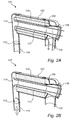
- Fig. 2A illustrates the catalytic converter 100 when the valve 118 is closed.
- the flow of exhaust gas is redirected by the deflector member 114 to flow through the volume 104 where the first catalytic converter substrate 106 is located and further through the first outlet 110, thus passing through the catalytic converter substrate 106.
- Fig. 2B illustrates the catalytic converter 100 when the valve 118 is open and when the exhaust gas flow directly out through the second outlet 116 without passing the volume 104 where the first catalytic converter substrate 106 is located.
- Fig 3 schematically illustrates a catalytic converter 300 where the deflector member 114 is configured to collect emissions in liquid form and to retain the emissions until the deflector member 114 has been heated such that the emissions evaporate into gaseous form.
- the deflector member 114 is at least partly provided with a layer 302 of porous material to absorb emissions in liquid or particulate form.
- the layer 302 of porous material is here arranged on the side wall of the deflector member 114 facing the flow of exhaust gas emissions from the pipe 112 so that the exhaust gas is guided directly towards the porous material by the pipe 112.
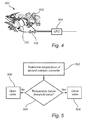
- Fig. 4 illustrates an exhaust-gas aftertreatment arrangement 400 comprising a first catalytic converter 100 according to any one of the embodiments described above.
- the first catalytic converter is a closed coupled converter arranged adjacent to an exhaust manifold 402 of a combustion engine.
- the aftertreatment arrangement 400 further comprises a second catalytic converter 404 arranged in series with and after the first catalytic converter.
- the second catalytic converter 404 is an underfloor converter (UFC) located downstream of and at a distance from the first catalytic converter 100.
- UDC underfloor converter
- the second catalytic converter 404 has an inlet which is connected to each of the first outlet 116 and the second outlet 110 of the first catalytic converter 100.
- the second catalytic converter 404 thus receives the flow of exhaust gas from the first catalytic converter 100 regardless of the position of the valve 118. Furthermore, in an embodiment of the invention, the valve 118 is controlled based on a temperature of a second catalytic converter substrate (not shown) of the second catalytic converter 404.
- the above described exhaust-gas aftertreatment arrangement 400 can ensure that the exhaust gas from the engine passes through the catalytic converter substrate 106 of the first catalytic converter 100 until the catalytic converter substrate of the second catalytic converter 404 has reached an acceptable operating temperature, thereby reducing the overall amount of emissions from the aftertreatment arrangement.
- the acceptable operating temperature can typically be in the range of 300 to 400°C, for example 350°C. However, the operating temperature may be different for different types of catalytic converters.
- Fig. 5 is a flow chart outlining the general functionality of the exhaust-gas aftertreatment arrangement 400 illustrated in Fig. 4 .
- the temperature of the second catalytic converter 404 is determined. For example, the operating temperature of the second catalytic converter 404 may be monitored continuously by a vehicle control system. Thereafter, the temperature is compared 504 to a threshold value, such as 350°C, and if the measured temperature is below the threshold value, the valve 118 is closed 506. If the measured temperature is above the threshold value, the valve 118 is opened 508.
- a threshold value such as 350°C
- the valve 118 is closed 506. If the measured temperature is above the threshold value, the valve 118 is opened 508.
- the temperature value can be seen as the trigger determining opening and closing of the valve
- the exhaust-gas aftertreatment arrangement 400 is here illustrated as comprising one UFC 404. However, it is equally possible to use two or more UFCs arranged in parallel after the first catalytic converter 100 for example in order to increase the effective area of catalytic conversion.
Landscapes
- Engineering & Computer Science (AREA)
- Chemical & Material Sciences (AREA)
- Chemical Kinetics & Catalysis (AREA)
- Combustion & Propulsion (AREA)
- Mechanical Engineering (AREA)
- General Engineering & Computer Science (AREA)
- Health & Medical Sciences (AREA)
- Toxicology (AREA)
- Materials Engineering (AREA)
- Exhaust Gas After Treatment (AREA)
Abstract
Description
- The present invention relates to an exhaust-gas aftertreatment arrangement for improving, particularly during cold start and warming-up, catalytic conversion of exhaust gas emissions from an internal combustion engine. In particular, the invention relates to an exhaust-gas aftertreatment device comprising a catalytic converter.
- A catalytic converter for a vehicle comprises in general a canned and coated catalytic converter substrate in flow communication with inlet and outlet passages. It is positioned on the exhaust side of the internal combustion engine of the vehicle in order to treat exhaust gas emissions from the engine.
- During cold start and warming-up of the engine, the catalytic converter is not sufficiently heated for optimum performance and the exhaust gas emissions may therefore pass through the catalytic converter without catalytic conversion thereof. To improve the heating properties, the catalytic converter is often positioned as close as possible to the exhaust ports. To accelerate heating, it is also possible to heat the catalytic converter electrically or to temporarily control combustion such that the temperature of the exhaust gas heat flow is increased.
- A frequent problem also particularly during cold start is that emissions in liquid form exit the engine. This may be caused by liquid fuel and oil which passes the engine during cranking of the engine, prior to combustion. Moreover, during cold start, exhaust gases might condense on cold walls and for liquid fuel and oil.
- A solution to one or more of the abovementioned problems used by some manufacturers is a so called hydrocarbon trap. Due to the fact that the catalytic converter substrate is not warm enough for catalytic conversion and that the concentration of hydrocarbon is high during cold start, a hydrocarbon trap where a trap material is coated on a typical catalytic converter substrate may be needed. The trap material stores hydrocarbon at low temperatures and releases hydrocarbon at higher temperatures. The trap material is, however, sensitive to aging.
- Moreover, catalytic converters typically need protection to avoid overheating which may otherwise occur at full load operation. Overheating can be avoided by over-fueling but that also causes the catalytic converter to operate at sub-optimal conditions, leading to an increase in tail-pipe emissions.
-
EP 2453113 provides an improved exhaust-gas aftertreatment device where deflector means are used to collect and retain emissions in liquid form in a cold start phase until the deflector means has been sufficiently heated for the emissions to evaporate. - However, there is still room for improvement of the above exhaust-gas aftertreatment device, in particular with respect to the life length of the catalytic converter material in high performance engines.
- In view of above-mentioned and other drawbacks of the prior art, it is an object of the present invention to provide an improved catalytic converter for an internal combustion engine which helps to reduce emissions and to improve the efficiency of the engine.
- According to a first aspect of the invention, there is provided a catalytic converter for an internal combustion engine, comprising: a tubular member which defines a volume within which a first catalytic converter substrate is located, and wherein the volume with the first catalytic converter substrate communicates with an inlet portion for receiving exhaust gas emissions from the internal combustion engine and with a first outlet portion for discharging the exhaust gas emissions after catalytic conversion thereof in the volume, a pipe member within the tubular member of the catalytic converter, which pipe member connects the inlet portion with the volume in the tubular member and guides the exhaust gas emissions from the inlet portion in a first direction of flow, and that the pipe member downstream opens into a deflector member which deflects the exhaust gas emissions into the volume of the tubular member of the catalytic converter in a second direction of flow different from the first direction of flow wherein the catalytic converter further comprises a second outlet portion connected to the deflector member, the second outlet portion comprising a valve configured to control a flow of exhaust gas through the second outlet portion to guide exhaust gas emissions away from the pipe member and out of the catalytic converter prior to reaching the first catalytic converter substrate when the valve is open.
- The present invention is based on the realization that an improved catalytic converter can be achieved by providing a second outlet controlled by a valve so that the flow of exhaust gas only passes the catalytic converter substrate during certain operating conditions of the engine. For example, during high performance operation of the engine, the valve is preferably open to allow the exhaust gas to bypass the first catalytic converter substrate, thereby reducing the back pressure experienced by the engine, and thereby reducing the catalyst temperature. Moreover, since the active components of the catalytic converter substrate are aged due to thermal exposure it is advantageous to minimize the amount of exhaust gas being passed through the catalytic converter substrate when it is not required. By opening the valve during high performance operation of the engine, it is also possible to avoid overheating of the catalytic converter which reduces the ageing thereby prolonging the life length of the catalytic converter.
- Furthermore, by providing the catalytic converter with a pipe member which is located within the tubular member of the catalytic converter and which connects the inlet portion with the volume in the tubular member and which guides the exhaust gas emissions from the inlet portion in a first direction of flow, and by ensuring that the pipe member downstream opens into a deflector member which deflects the exhaust gas emissions into the volume of the tubular member of the catalytic converter in a second direction of flow substantially opposite to said first direction of flow, when the valve is closed, the period of time before the exhaust gas emissions reach the catalytic converter is increased and mixing of the exhaust gas emissions during this period of time is improved.
- According to one embodiment of the invention, the valve is preferably closed during a cold start phase of the engine. At the cold start phase of the engine, due in part to incomplete combustion, the emissions in the exhaust gas are typically higher than during normal operation when the engine is warm. Accordingly, by closing the valve during a cold start phase, the exhaust gas is forced through the first catalytic converter substrate, thereby reducing the emissions of the exhaust gas. Once the engine has reached a suitable operating temperature, the valve can be opened to reduce the back pressure as discussed above.
- In one embodiment of the invention the valve may be controlled based on a mass flow of exhaust gas from the engine. When the engine is operating in a high-performance mode, i.e. at high rpm, the mass flow of the exhaust gas is likewise high. In order to maximize the performance of the engine, and at the same time reduce the thermal load of the catalytic converter, it is desirable to reduce the back pressure from the catalytic converter which is achieved by opening the valve and allowing exhaust gas to flow unhindered via the second outlet.
- According to one embodiment of the invention, the valve is may advantageously be an on/off valve which provides a simple way of operating the valve without the need for control mechanisms for determining a degree of opening. Thus, the valve is either fully open or fully closed. However, the skilled person readily realizes that a variable valve may equally well be used to the same effect.
- According to one embodiment of the invention, the deflector member of the catalytic converter may further be configured to collect emissions in liquid form and to retain the emissions until the deflector means has been heated such that the emissions evaporate into gaseous form, wherein the deflector member, on the side wall thereof facing the flow of exhaust gas emissions, is at least partly provided with a layer of porous material to absorb emissions in liquid or particulate form.
- That the deflector means of said device is configured such that it can collect emissions in liquid form in the exhaust gas emissions and retain these emissions in liquid form until the operating temperature of the device and, of course, of the catalytic converter is such that said emissions in liquid form evaporate into gaseous form will further increase the dwell time of the exhaust gas emissions in the device to ensure that the emissions in liquid form therein are adequately transformed into gaseous form and consequently improve mixing thereof before performing the catalytic conversion, and thereby further improve the performance of the catalytic converter.
- According to one embodiment of the invention, there is provided an exhaust-gas aftertreatment arrangement comprising a first catalytic converter according to any one of the embodiments described above, wherein the first catalytic converter is a closed coupled converter arranged adjacent to an exhaust manifold of the engine; and second catalytic converter arranged in series with and after said first catalytic converter, wherein the valve is controlled based on a temperature of a second catalytic converter substrate of said second catalytic converter.
- That the first catalytic converter is a so called close coupled catalytic converter (CCC) arranged as close as possible to the exhaust manifold of the engine has the effect that it is heated faster than a catalytic converter for example arranged under the floor of the vehicle, i.e. an under floor converter (UFC). Moreover, it is known that the catalytic process taking place at the catalytic converter substrate is most efficient at an elevated temperature, and that the degree of emissions therefore may be higher during a cold start phase of the engine. The close coupled converter heats up quickly, due to its exposure to the very hot exhaust gases directly from the engine, enabling it to reduce undesirable emissions during the engine warm-up period. This is achieved by burning off the excess hydrocarbons which result from the extra-rich mixture required for a cold start.
- According to one embodiment of the invention, the valve may be controlled based on a temperature of the second catalytic converter substrate. Thereby, the use of a close coupled converter in combination with an underfloor converter, along with a valve controlling the flow through the first catalytic converter, enables a selection so that the close coupled converter can be used only when desired. The close coupled converter can be used during a cold start phase until the catalytic substrate of the second converter has reached a sufficiently high temperature so that the exhaust gas is passed through both the first and the second catalytic converter during a cold start phase. After the operating temperature of the second catalytic converter has been reached, the valve can be opened so that the exhaust gas bypasses the first catalytic converter substrate, thus being directly lead to the second catalytic converter. Thereby, undesirable back pressure can be avoided which in turn improves the fuel efficiency and decreases the tailpipe emissions of the engine.
- In one embodiment of the invention, the valve may be configured to be closed if a temperature of the second catalytic converter substrate is below a predetermined threshold value, the second predetermined threshold value being in the range of 300 to 400°C. In particular, the predetermined temperature threshold value may be approximately 350°C. The threshold value is based on the efficiency of the catalytic converter substrate at different temperatures and may be set according to the specific catalyst used and according to specific requirements with regards to exhaust emission levels. Thereby, the first catalytic converter can be activated if operating temperature of the second catalytic converter becomes too low.
- According to a second aspect of the invention, there is provided a method for controlling an exhaust-gas aftertreatment arrangement comprising: a first catalytic converter comprising: a tubular member which defines a volume within which a catalytic converter substrate is located, and wherein the volume with the catalytic converter substrate communicates with an inlet portion for receiving exhaust gas emissions from the internal combustion engine and with a first outlet portion for discharging the exhaust gas emissions after catalytic conversion thereof in the volume, a pipe member within the tubular member of the catalytic converter, which pipe member connects the inlet portion with the volume in the tubular member and guides the exhaust gas emissions from the inlet portion in a first direction of flow, and that the pipe member downstream opens into a deflector member which deflects the exhaust gas emissions into the volume of the tubular member of the catalytic converter in a second direction of flow different from the first direction of flow, wherein the catalytic converter further comprises a second outlet portion connected to the deflector member configured to guide exhaust gas emissions away from the pipe member and out of the catalytic converter prior to reaching the catalytic converter substrate, the second outlet portion comprising a valve configured to control a flow of exhaust gas through the second outlet portion; the first catalytic converter being a closed coupled converter arranged adjacent to an exhaust manifold of the engine; and a second catalytic converter arranged in series with and after the first catalytic converter and comprising an inlet connected to the first and second outlet of the first catalytic converter; the second catalytic converter further comprising a second catalytic converter substrate; the method comprising: determining a temperature of the second catalytic converter substrate; if the temperature is below a predetermined temperature threshold value, close the valve.
- The predetermined temperature threshold value may preferably be in the range of 300 °C to 400 °C, and more preferably the predetermined temperature threshold value may be approximately 350°C.
- Effects and features of the second aspect of the invention are largely analogous to those described above in connection with the first aspect of the invention.
- Further features of, and advantages with, the present invention will become apparent when studying the appended claims and the following description. The skilled person realize that different features of the present invention may be combined to create embodiments other than those described in the following, without departing from the scope of the present invention.
- These and other aspects of the present invention will now be described in more detail, with reference to the appended drawings showing an example embodiment of the invention, wherein:
-
Fig. 1 schematically illustrates a catalytic converter according to an embodiment of the invention; -
Figs. 2A-B schematically illustrate catalytic converters according to embodiments of the invention; -
Fig. 3 schematically illustrates a catalytic converter according to an embodiment of the invention; -
Fig. 4 schematically illustrates an exhaust-gas aftertreatment arrangement according to an embodiment of the invention; and -
Fig. 5 is a flow chart outlining the general steps of a method according to an embodiment of the invention. - In the present detailed description, various embodiments of the system and method according to the present invention are mainly described with reference to a catalytic converter in an exhaust-gas aftertreatment arrangement for a combustion engine.
-
Fig. 1 schematically illustrates acatalytic converter 100. Thecatalytic converter 100 comprises atubular member 102 which defines avolume 104 within which a firstcatalytic converter substrate 106 is located. Thevolume 104 with the firstcatalytic converter substrate 106 communicates with aninlet portion 108 for receiving an exhaust gas flow from the exhaust manifold of an internal combustion engine. A catalytic converter which is arranged directly adjacent to the exhaust manifold of a combustion engine is often referred to as a close coupled catalytic converter (CCC). Thecatalytic converter 100 further comprises afirst outlet portion 110 for discharging the exhaust gas flow after catalytic conversion thereof in thevolume 104. Atubular pipe member 112 within thetubular member 102 of thecatalytic converter 100 connects theinlet portion 108 with thevolume 104 in thetubular member 102 and guides the exhaust gas from theinlet portion 108 in a first direction of flow, inFig. 1 illustrated from left to right, i.e. from theinlet 108 and through thepipe member 112. The downstream portion of thepipe member 112, opposite theinlet 108, opens into adeflector member 114 which deflects the exhaust gas into thevolume 104 of thetubular member 102 of thecatalytic converter 102 in a second direction of flow different from the first direction of flow. Here, the second direction of flow is opposite the first direction of flow. Thecatalytic converter 100 further comprises asecond outlet portion 116 connected to thedeflector member 114, thesecond outlet portion 116 comprising avalve 118 configured to control a flow of exhaust gas through thesecond outlet portion 116 to guide exhaust gas emissions away from thepipe member 112 and out of thecatalytic converter 100 prior to reaching the firstcatalytic converter substrate 106 when thevalve 118 is open. Thereby, thevalve 118 controls if the exhaust flow from the combustion engine passes through the firstcatalytic converter substrate 106 or not. Thevalve 118 can for example be an on/off valve which is controlled based on a measured parameter value or on a mode of operation of the combustion engine. Thevalve 118 may also be a variable valve controlled based on the above parameters. Moreover, it is desirable that thevalve 118 is closed during a cold start phase of the engine where the emissions are typically higher and when it is more important that the exhaust gas passes through thecatalytic converter substrate 106. -
Fig. 2A illustrates thecatalytic converter 100 when thevalve 118 is closed. Here it can be seen that the flow of exhaust gas is redirected by thedeflector member 114 to flow through thevolume 104 where the firstcatalytic converter substrate 106 is located and further through thefirst outlet 110, thus passing through thecatalytic converter substrate 106. -
Fig. 2B illustrates thecatalytic converter 100 when thevalve 118 is open and when the exhaust gas flow directly out through thesecond outlet 116 without passing thevolume 104 where the firstcatalytic converter substrate 106 is located. -
Fig 3 schematically illustrates a catalytic converter 300 where thedeflector member 114 is configured to collect emissions in liquid form and to retain the emissions until thedeflector member 114 has been heated such that the emissions evaporate into gaseous form. To achieve this, thedeflector member 114 is at least partly provided with alayer 302 of porous material to absorb emissions in liquid or particulate form. Thelayer 302 of porous material is here arranged on the side wall of thedeflector member 114 facing the flow of exhaust gas emissions from thepipe 112 so that the exhaust gas is guided directly towards the porous material by thepipe 112. -
Fig. 4 illustrates an exhaust-gas aftertreatment arrangement 400 comprising a firstcatalytic converter 100 according to any one of the embodiments described above. The first catalytic converter is a closed coupled converter arranged adjacent to anexhaust manifold 402 of a combustion engine. Theaftertreatment arrangement 400 further comprises a secondcatalytic converter 404 arranged in series with and after the first catalytic converter. The secondcatalytic converter 404 is an underfloor converter (UFC) located downstream of and at a distance from the firstcatalytic converter 100. The secondcatalytic converter 404 has an inlet which is connected to each of thefirst outlet 116 and thesecond outlet 110 of the firstcatalytic converter 100. The secondcatalytic converter 404 thus receives the flow of exhaust gas from the firstcatalytic converter 100 regardless of the position of thevalve 118. Furthermore, in an embodiment of the invention, thevalve 118 is controlled based on a temperature of a second catalytic converter substrate (not shown) of the secondcatalytic converter 404. Thereby, the above described exhaust-gas aftertreatment arrangement 400 can ensure that the exhaust gas from the engine passes through thecatalytic converter substrate 106 of the firstcatalytic converter 100 until the catalytic converter substrate of the secondcatalytic converter 404 has reached an acceptable operating temperature, thereby reducing the overall amount of emissions from the aftertreatment arrangement. The acceptable operating temperature can typically be in the range of 300 to 400°C, for example 350°C. However, the operating temperature may be different for different types of catalytic converters. -
Fig. 5 is a flow chart outlining the general functionality of the exhaust-gas aftertreatment arrangement 400 illustrated inFig. 4 . In afirst step 502, the temperature of the secondcatalytic converter 404 is determined. For example, the operating temperature of the secondcatalytic converter 404 may be monitored continuously by a vehicle control system. Thereafter, the temperature is compared 504 to a threshold value, such as 350°C, and if the measured temperature is below the threshold value, thevalve 118 is closed 506. If the measured temperature is above the threshold value, thevalve 118 is opened 508. In practice the temperature value can be seen as the trigger determining opening and closing of the valve - The exhaust-
gas aftertreatment arrangement 400 is here illustrated as comprising oneUFC 404. However, it is equally possible to use two or more UFCs arranged in parallel after the firstcatalytic converter 100 for example in order to increase the effective area of catalytic conversion. - Even though the invention has been described with reference to specific exemplifying embodiments thereof, many different alterations, modifications and the like will become apparent for those skilled in the art. Also, it should be noted that parts of the device may be omitted, interchanged or arranged in various ways, the device yet being able to perform the functionality of the present invention.
- Additionally, variations to the disclosed embodiments can be understood and effected by the skilled person in practicing the claimed invention, from a study of the drawings, the disclosure, and the appended claims. In the claims, the word "comprising" does not exclude other elements or steps, and the indefinite article "a" or "an" does not exclude a plurality. The mere fact that certain measures are recited in mutually different dependent claims does not indicate that a combination of these measures cannot be used to advantage.
Claims (13)
- A catalytic converter (100) for an internal combustion engine, comprising:a tubular member (102) which defines a volume (104) within which a first catalytic converter substrate (106) is located, and wherein the volume with the first catalytic converter substrate communicates with an inlet portion (108) for receiving exhaust gas emissions from the internal combustion engine and with a first outlet portion (110) for discharging said exhaust gas emissions after catalytic conversion thereof in said volume,a pipe member (112) within said tubular member of said first catalytic converter, which pipe member connects the inlet portion with the volume in said tubular member and guides the exhaust gas emissions from said inlet portion in a first direction of flow, and that said pipe member downstream opens into a deflector member (114) which deflects the exhaust gas emissions into the volume of the tubular member of the catalytic converter in a second direction of flow different from said first direction of flow,wherein said catalytic converter further comprises a second outlet portion (116) connected to said deflector member, said second outlet portion comprising a valve (118) configured to control a flow of exhaust gas through said second outlet portion to guide exhaust gas emissions away from said pipe member and out of said catalytic converter prior to reaching said first catalytic converter substrate when said valve is open.
- The catalytic converter according to claim 1, wherein said valve is configured to be closed during a cold start phase of said engine.
- The catalytic converter according to claim 1 or 2, wherein said valve is configured to be closed for at least 30s after a cold start of said engine.
- The device according to any one of the preceding claims, wherein said valve is configured to be controlled based on a mass flow of exhaust gas from said engine.
- The device according to any one of the preceding claims, wherein said valve is an on/off valve.
- The device according to any one of the preceding claims, wherein the deflector member (114) is configured to collect emissions in liquid form and to retain said emissions until said deflector means has been heated such that said emissions evaporate into gaseous form, wherein the deflector member, on the side wall thereof facing the flow of exhaust gas emissions, is at least partly provided with a layer (302) of porous material to absorb emissions in liquid or particulate form.
- An exhaust-gas aftertreatment arrangement (400) comprising:a first catalytic converter (100) according to any one of the preceding claims, said first catalytic converter being a closed coupled converter arranged adjacent to an exhaust manifold of said engine; anda second catalytic converter (404) arranged in series with and after said first catalytic converter, said second catalytic converter having an inlet connected to each of said first outlet and said second outlet, wherein said valve (118) is configured to be controlled based on a temperature of a second catalytic converter substrate of said second catalytic converter.
- The arrangement according to claim 7, wherein said valve is configured to be controlled based on a temperature of said second catalytic converter substrate.
- The arrangement according to claim 8, wherein said valve is configured to be closed if a temperature of said second catalytic converter substrate is below a predetermined threshold value, said predetermined threshold value being in the range of 300 to 400°C.
- The method according to claim 9, wherein said predetermined threshold value is approximately 350°C.
- A method for controlling an exhaust-gas aftertreatment arrangement comprising:a first catalytic converter (100) comprising:a tubular member (102) which defines a volume (104) within which a catalytic converter substrate (106) is located, and wherein the volume with the catalytic converter substrate communicates with an inlet portion (108) for receiving exhaust gas emissions from the internal combustion engine and with a first outlet portion (110) for discharging said exhaust gas emissions after catalytic conversion thereof in said volume,a pipe member (112) within said tubular member of said first catalytic converter, which pipe member connects the inlet portion with the volume in said tubular member and guides the exhaust gas emissions from said inlet portion in a first direction of flow, and that said pipe member downstream opens into a deflector member (114) which deflects the exhaust gas emissions into the volume of the tubular member of the catalytic converter in a second direction of flow different from said first direction of flow,wherein said catalytic converter further comprises a second outlet portion (116) connected to said deflector member, said second outlet portion comprising a valve (118) configured to control a flow of exhaust gas through said second outlet portion to guide exhaust gas emissions away from said pipe member and out of said catalytic converter prior to reaching said first catalytic converter substrate when said valve is open;said first catalytic converter being a closed coupled converter arranged adjacent to an exhaust manifold of said engine; anda second catalytic converter (404) arranged in series with and after said first catalytic converter and comprising an inlet connected to said first and second outlet of said first catalytic converter, said second catalytic converter comprising a second catalytic converter substrate;said method comprising:determining (502) a temperature of said second catalytic converter substrate;if said temperature is below a predetermined temperature threshold value, close (506) said valve; andif said temperature is above said predetermined temperature threshold value, open (508) said valve.
- The method according to claim 11, wherein said predetermined temperature threshold value is in the range of 300°C to 400°C.
- The method according to claim 12, wherein said predetermined temperature threshold value is approximately 350°C.
Priority Applications (3)
| Application Number | Priority Date | Filing Date | Title |
|---|---|---|---|
| EP15202306.5A EP3184767B1 (en) | 2015-12-23 | 2015-12-23 | Catalytic converter and exhaust-gas aftertreatment arrangement |
| CN201611233015.8A CN106907219B (en) | 2015-12-23 | 2016-12-15 | Catalytic converters and exhaust aftertreatment equipment |
| US15/380,174 US10107166B2 (en) | 2015-12-23 | 2016-12-15 | Catalytic converter and exhaust-gas aftertreatment arrangement |
Applications Claiming Priority (1)
| Application Number | Priority Date | Filing Date | Title |
|---|---|---|---|
| EP15202306.5A EP3184767B1 (en) | 2015-12-23 | 2015-12-23 | Catalytic converter and exhaust-gas aftertreatment arrangement |
Publications (2)
| Publication Number | Publication Date |
|---|---|
| EP3184767A1 true EP3184767A1 (en) | 2017-06-28 |
| EP3184767B1 EP3184767B1 (en) | 2019-07-03 |
Family
ID=55079966
Family Applications (1)
| Application Number | Title | Priority Date | Filing Date |
|---|---|---|---|
| EP15202306.5A Active EP3184767B1 (en) | 2015-12-23 | 2015-12-23 | Catalytic converter and exhaust-gas aftertreatment arrangement |
Country Status (3)
| Country | Link |
|---|---|
| US (1) | US10107166B2 (en) |
| EP (1) | EP3184767B1 (en) |
| CN (1) | CN106907219B (en) |
Cited By (1)
| Publication number | Priority date | Publication date | Assignee | Title |
|---|---|---|---|---|
| WO2020260333A1 (en) * | 2019-06-26 | 2020-12-30 | Vitesco Technologies GmbH | Exhaust gas aftertreatment device |
Families Citing this family (2)
| Publication number | Priority date | Publication date | Assignee | Title |
|---|---|---|---|---|
| CN107401444A (en) * | 2017-09-26 | 2017-11-28 | 日照职业技术学院 | Motor car exhaust gas catalysis reforming unit |
| KR102727900B1 (en) * | 2019-05-02 | 2024-11-07 | 현대자동차주식회사 | Exhaust system for vehicle |
Citations (4)
| Publication number | Priority date | Publication date | Assignee | Title |
|---|---|---|---|---|
| US5277026A (en) * | 1992-02-22 | 1994-01-11 | Mercedes-Benz Ag | Internal combustion engine exhaust system |
| EP0953738A2 (en) * | 1998-04-28 | 1999-11-03 | Toyota Jidosha Kabushiki Kaisha | Exhaust emission control system of internal combustion engine |
| EP2453113A1 (en) | 2010-11-10 | 2012-05-16 | Volvo Car Corporation | Exhaust-gas aftertreatment device |
| EP2873821A1 (en) * | 2013-11-15 | 2015-05-20 | Volvo Car Corporation | Exhaust gas aftertreatment device |
Family Cites Families (12)
| Publication number | Priority date | Publication date | Assignee | Title |
|---|---|---|---|---|
| US3937015A (en) * | 1973-05-03 | 1976-02-10 | Nippondenso Co., Ltd. | Pleated filter in the exhaust manifold |
| US5331810A (en) * | 1992-05-21 | 1994-07-26 | Arvin Industries, Inc. | Low thermal capacitance exhaust system for an internal combustion engine |
| JPH10511038A (en) * | 1995-06-28 | 1998-10-27 | シーメンス アクチエンゲゼルシヤフト | Method and apparatus for purifying catalyst from exhaust gas from combustion equipment |
| JP3557925B2 (en) * | 1998-12-22 | 2004-08-25 | トヨタ自動車株式会社 | Exhaust gas purification device for internal combustion engine |
| GB9915939D0 (en) * | 1999-07-08 | 1999-09-08 | Johnson Matthey Plc | Improvements in pollution control |
| CN1262741C (en) * | 2003-05-18 | 2006-07-05 | 吉林大学 | Naturally preheating and exhaust-lowering engine cold starting device |
| KR100590960B1 (en) * | 2004-04-06 | 2006-06-19 | 현대자동차주식회사 | Automobile Exhaust Gas Purification System |
| JP4534860B2 (en) * | 2004-12-15 | 2010-09-01 | トヨタ自動車株式会社 | Engine exhaust purification device and method of manufacturing the same |
| GB2425493B (en) * | 2005-04-28 | 2008-08-27 | Ford Global Tech Llc | An emission control system for an engine |
| JP4197039B2 (en) * | 2007-03-28 | 2008-12-17 | トヨタ自動車株式会社 | POWER OUTPUT DEVICE, VEHICLE MOUNTING THE SAME, AND METHOD FOR CONTROLLING POWER OUTPUT DEVICE |
| GB0721528D0 (en) * | 2007-11-02 | 2007-12-12 | T Baden Hardstaff Ltd | Exhaust system |
| DE102013210799C5 (en) * | 2013-06-10 | 2020-07-09 | Eberspächer Exhaust Technology GmbH & Co. KG | Exhaust system of an internal combustion engine |
-
2015
- 2015-12-23 EP EP15202306.5A patent/EP3184767B1/en active Active
-
2016
- 2016-12-15 CN CN201611233015.8A patent/CN106907219B/en active Active
- 2016-12-15 US US15/380,174 patent/US10107166B2/en active Active
Patent Citations (4)
| Publication number | Priority date | Publication date | Assignee | Title |
|---|---|---|---|---|
| US5277026A (en) * | 1992-02-22 | 1994-01-11 | Mercedes-Benz Ag | Internal combustion engine exhaust system |
| EP0953738A2 (en) * | 1998-04-28 | 1999-11-03 | Toyota Jidosha Kabushiki Kaisha | Exhaust emission control system of internal combustion engine |
| EP2453113A1 (en) | 2010-11-10 | 2012-05-16 | Volvo Car Corporation | Exhaust-gas aftertreatment device |
| EP2873821A1 (en) * | 2013-11-15 | 2015-05-20 | Volvo Car Corporation | Exhaust gas aftertreatment device |
Cited By (1)
| Publication number | Priority date | Publication date | Assignee | Title |
|---|---|---|---|---|
| WO2020260333A1 (en) * | 2019-06-26 | 2020-12-30 | Vitesco Technologies GmbH | Exhaust gas aftertreatment device |
Also Published As
| Publication number | Publication date |
|---|---|
| EP3184767B1 (en) | 2019-07-03 |
| CN106907219A (en) | 2017-06-30 |
| US20170184001A1 (en) | 2017-06-29 |
| US10107166B2 (en) | 2018-10-23 |
| CN106907219B (en) | 2020-09-01 |
Similar Documents
| Publication | Publication Date | Title |
|---|---|---|
| US10830116B2 (en) | Exhaust gas system and method for operating an exhaust gas system | |
| US10989084B2 (en) | Exhaust gas system with preconditioning | |
| CN109424400A (en) | The heating of active catalyst | |
| CN101988427B (en) | Engine exhaust system and its control method | |
| CN106437973B (en) | Method for exhaust gas aftertreatment of internal combustion engines and device for carrying out the method | |
| CN103443416B (en) | For heat energy being inputted the method in off-gas cleaning equipment | |
| US20130186074A1 (en) | Internal combustion engine | |
| CN110945220A (en) | Exhaust gas aftertreatment system and method for exhaust gas aftertreatment of an internal combustion engine | |
| US20080120966A1 (en) | Exhaust Gas Purification System for Internal Combustion Engine | |
| US20100095673A1 (en) | Internal combustion engine having turbocharging and low-pressure exhaust-gas recirculation | |
| JP6570665B2 (en) | Exhaust gas equipment | |
| US10107166B2 (en) | Catalytic converter and exhaust-gas aftertreatment arrangement | |
| CN107023356A (en) | Exhaust heat recovery and hydrocarbon trapping | |
| EP2453113B1 (en) | Exhaust-gas aftertreatment device | |
| US10145287B2 (en) | Dual catalytic converter exhaust-gas aftertreatment arrangement | |
| US20160273433A1 (en) | Exhaust gas treatment apparatus and exhaust gas treatment method for internal combustion engine | |
| EP2022968A1 (en) | Air-fuel ratio control device | |
| JP4483359B2 (en) | Internal combustion engine warm-up device | |
| US20200408124A1 (en) | Exhaust component with a helical heater | |
| US20230175423A1 (en) | Exhaust After Treatment System and Method for Pre-Heating a Catalytic Converter | |
| CN215719042U (en) | Bypass type automobile engine catalyst converter system of igniting fast | |
| NL2029161B1 (en) | An exhaust after treatment assembly. | |
| EP1890017A1 (en) | Internal combustion engine and method of controlling the same | |
| US20250137395A1 (en) | Cold start catalyst bypass system | |
| EP3527795A1 (en) | Gas engine system |
Legal Events
| Date | Code | Title | Description |
|---|---|---|---|
| PUAI | Public reference made under article 153(3) epc to a published international application that has entered the european phase |
Free format text: ORIGINAL CODE: 0009012 |
|
| STAA | Information on the status of an ep patent application or granted ep patent |
Free format text: STATUS: THE APPLICATION HAS BEEN PUBLISHED |
|
| AK | Designated contracting states |
Kind code of ref document: A1 Designated state(s): AL AT BE BG CH CY CZ DE DK EE ES FI FR GB GR HR HU IE IS IT LI LT LU LV MC MK MT NL NO PL PT RO RS SE SI SK SM TR |
|
| AX | Request for extension of the european patent |
Extension state: BA ME |
|
| STAA | Information on the status of an ep patent application or granted ep patent |
Free format text: STATUS: REQUEST FOR EXAMINATION WAS MADE |
|
| 17P | Request for examination filed |
Effective date: 20180102 |
|
| RBV | Designated contracting states (corrected) |
Designated state(s): AL AT BE BG CH CY CZ DE DK EE ES FI FR GB GR HR HU IE IS IT LI LT LU LV MC MK MT NL NO PL PT RO RS SE SI SK SM TR |
|
| STAA | Information on the status of an ep patent application or granted ep patent |
Free format text: STATUS: EXAMINATION IS IN PROGRESS |
|
| 17Q | First examination report despatched |
Effective date: 20180731 |
|
| GRAP | Despatch of communication of intention to grant a patent |
Free format text: ORIGINAL CODE: EPIDOSNIGR1 |
|
| STAA | Information on the status of an ep patent application or granted ep patent |
Free format text: STATUS: GRANT OF PATENT IS INTENDED |
|
| INTG | Intention to grant announced |
Effective date: 20190206 |
|
| GRAS | Grant fee paid |
Free format text: ORIGINAL CODE: EPIDOSNIGR3 |
|
| GRAA | (expected) grant |
Free format text: ORIGINAL CODE: 0009210 |
|
| STAA | Information on the status of an ep patent application or granted ep patent |
Free format text: STATUS: THE PATENT HAS BEEN GRANTED |
|
| AK | Designated contracting states |
Kind code of ref document: B1 Designated state(s): AL AT BE BG CH CY CZ DE DK EE ES FI FR GB GR HR HU IE IS IT LI LT LU LV MC MK MT NL NO PL PT RO RS SE SI SK SM TR |
|
| REG | Reference to a national code |
Ref country code: GB Ref legal event code: FG4D |
|
| REG | Reference to a national code |
Ref country code: CH Ref legal event code: EP Ref country code: AT Ref legal event code: REF Ref document number: 1151267 Country of ref document: AT Kind code of ref document: T Effective date: 20190715 |
|
| REG | Reference to a national code |
Ref country code: IE Ref legal event code: FG4D |
|
| REG | Reference to a national code |
Ref country code: DE Ref legal event code: R096 Ref document number: 602015033045 Country of ref document: DE |
|
| REG | Reference to a national code |
Ref country code: NL Ref legal event code: MP Effective date: 20190703 |
|
| REG | Reference to a national code |
Ref country code: LT Ref legal event code: MG4D |
|
| REG | Reference to a national code |
Ref country code: AT Ref legal event code: MK05 Ref document number: 1151267 Country of ref document: AT Kind code of ref document: T Effective date: 20190703 |
|
| PG25 | Lapsed in a contracting state [announced via postgrant information from national office to epo] |
Ref country code: CZ Free format text: LAPSE BECAUSE OF FAILURE TO SUBMIT A TRANSLATION OF THE DESCRIPTION OR TO PAY THE FEE WITHIN THE PRESCRIBED TIME-LIMIT Effective date: 20190703 Ref country code: HR Free format text: LAPSE BECAUSE OF FAILURE TO SUBMIT A TRANSLATION OF THE DESCRIPTION OR TO PAY THE FEE WITHIN THE PRESCRIBED TIME-LIMIT Effective date: 20190703 Ref country code: LT Free format text: LAPSE BECAUSE OF FAILURE TO SUBMIT A TRANSLATION OF THE DESCRIPTION OR TO PAY THE FEE WITHIN THE PRESCRIBED TIME-LIMIT Effective date: 20190703 Ref country code: SE Free format text: LAPSE BECAUSE OF FAILURE TO SUBMIT A TRANSLATION OF THE DESCRIPTION OR TO PAY THE FEE WITHIN THE PRESCRIBED TIME-LIMIT Effective date: 20190703 Ref country code: BG Free format text: LAPSE BECAUSE OF FAILURE TO SUBMIT A TRANSLATION OF THE DESCRIPTION OR TO PAY THE FEE WITHIN THE PRESCRIBED TIME-LIMIT Effective date: 20191003 Ref country code: PT Free format text: LAPSE BECAUSE OF FAILURE TO SUBMIT A TRANSLATION OF THE DESCRIPTION OR TO PAY THE FEE WITHIN THE PRESCRIBED TIME-LIMIT Effective date: 20191104 Ref country code: NL Free format text: LAPSE BECAUSE OF FAILURE TO SUBMIT A TRANSLATION OF THE DESCRIPTION OR TO PAY THE FEE WITHIN THE PRESCRIBED TIME-LIMIT Effective date: 20190703 Ref country code: FI Free format text: LAPSE BECAUSE OF FAILURE TO SUBMIT A TRANSLATION OF THE DESCRIPTION OR TO PAY THE FEE WITHIN THE PRESCRIBED TIME-LIMIT Effective date: 20190703 Ref country code: NO Free format text: LAPSE BECAUSE OF FAILURE TO SUBMIT A TRANSLATION OF THE DESCRIPTION OR TO PAY THE FEE WITHIN THE PRESCRIBED TIME-LIMIT Effective date: 20191003 Ref country code: AT Free format text: LAPSE BECAUSE OF FAILURE TO SUBMIT A TRANSLATION OF THE DESCRIPTION OR TO PAY THE FEE WITHIN THE PRESCRIBED TIME-LIMIT Effective date: 20190703 |
|
| PG25 | Lapsed in a contracting state [announced via postgrant information from national office to epo] |
Ref country code: ES Free format text: LAPSE BECAUSE OF FAILURE TO SUBMIT A TRANSLATION OF THE DESCRIPTION OR TO PAY THE FEE WITHIN THE PRESCRIBED TIME-LIMIT Effective date: 20190703 Ref country code: LV Free format text: LAPSE BECAUSE OF FAILURE TO SUBMIT A TRANSLATION OF THE DESCRIPTION OR TO PAY THE FEE WITHIN THE PRESCRIBED TIME-LIMIT Effective date: 20190703 Ref country code: IS Free format text: LAPSE BECAUSE OF FAILURE TO SUBMIT A TRANSLATION OF THE DESCRIPTION OR TO PAY THE FEE WITHIN THE PRESCRIBED TIME-LIMIT Effective date: 20191103 Ref country code: AL Free format text: LAPSE BECAUSE OF FAILURE TO SUBMIT A TRANSLATION OF THE DESCRIPTION OR TO PAY THE FEE WITHIN THE PRESCRIBED TIME-LIMIT Effective date: 20190703 Ref country code: GR Free format text: LAPSE BECAUSE OF FAILURE TO SUBMIT A TRANSLATION OF THE DESCRIPTION OR TO PAY THE FEE WITHIN THE PRESCRIBED TIME-LIMIT Effective date: 20191004 Ref country code: RS Free format text: LAPSE BECAUSE OF FAILURE TO SUBMIT A TRANSLATION OF THE DESCRIPTION OR TO PAY THE FEE WITHIN THE PRESCRIBED TIME-LIMIT Effective date: 20190703 |
|
| PG25 | Lapsed in a contracting state [announced via postgrant information from national office to epo] |
Ref country code: TR Free format text: LAPSE BECAUSE OF FAILURE TO SUBMIT A TRANSLATION OF THE DESCRIPTION OR TO PAY THE FEE WITHIN THE PRESCRIBED TIME-LIMIT Effective date: 20190703 |
|
| PG25 | Lapsed in a contracting state [announced via postgrant information from national office to epo] |
Ref country code: EE Free format text: LAPSE BECAUSE OF FAILURE TO SUBMIT A TRANSLATION OF THE DESCRIPTION OR TO PAY THE FEE WITHIN THE PRESCRIBED TIME-LIMIT Effective date: 20190703 Ref country code: RO Free format text: LAPSE BECAUSE OF FAILURE TO SUBMIT A TRANSLATION OF THE DESCRIPTION OR TO PAY THE FEE WITHIN THE PRESCRIBED TIME-LIMIT Effective date: 20190703 Ref country code: DK Free format text: LAPSE BECAUSE OF FAILURE TO SUBMIT A TRANSLATION OF THE DESCRIPTION OR TO PAY THE FEE WITHIN THE PRESCRIBED TIME-LIMIT Effective date: 20190703 Ref country code: PL Free format text: LAPSE BECAUSE OF FAILURE TO SUBMIT A TRANSLATION OF THE DESCRIPTION OR TO PAY THE FEE WITHIN THE PRESCRIBED TIME-LIMIT Effective date: 20190703 |
|
| PG25 | Lapsed in a contracting state [announced via postgrant information from national office to epo] |
Ref country code: SK Free format text: LAPSE BECAUSE OF FAILURE TO SUBMIT A TRANSLATION OF THE DESCRIPTION OR TO PAY THE FEE WITHIN THE PRESCRIBED TIME-LIMIT Effective date: 20190703 Ref country code: SM Free format text: LAPSE BECAUSE OF FAILURE TO SUBMIT A TRANSLATION OF THE DESCRIPTION OR TO PAY THE FEE WITHIN THE PRESCRIBED TIME-LIMIT Effective date: 20190703 Ref country code: IS Free format text: LAPSE BECAUSE OF FAILURE TO SUBMIT A TRANSLATION OF THE DESCRIPTION OR TO PAY THE FEE WITHIN THE PRESCRIBED TIME-LIMIT Effective date: 20200224 |
|
| REG | Reference to a national code |
Ref country code: DE Ref legal event code: R097 Ref document number: 602015033045 Country of ref document: DE |
|
| PLBE | No opposition filed within time limit |
Free format text: ORIGINAL CODE: 0009261 |
|
| STAA | Information on the status of an ep patent application or granted ep patent |
Free format text: STATUS: NO OPPOSITION FILED WITHIN TIME LIMIT |
|
| PG2D | Information on lapse in contracting state deleted |
Ref country code: IS |
|
| REG | Reference to a national code |
Ref country code: CH Ref legal event code: PL |
|
| 26N | No opposition filed |
Effective date: 20200603 |
|
| REG | Reference to a national code |
Ref country code: BE Ref legal event code: MM Effective date: 20191231 |
|
| PG25 | Lapsed in a contracting state [announced via postgrant information from national office to epo] |
Ref country code: MC Free format text: LAPSE BECAUSE OF FAILURE TO SUBMIT A TRANSLATION OF THE DESCRIPTION OR TO PAY THE FEE WITHIN THE PRESCRIBED TIME-LIMIT Effective date: 20190703 Ref country code: SI Free format text: LAPSE BECAUSE OF FAILURE TO SUBMIT A TRANSLATION OF THE DESCRIPTION OR TO PAY THE FEE WITHIN THE PRESCRIBED TIME-LIMIT Effective date: 20190703 |
|
| GBPC | Gb: european patent ceased through non-payment of renewal fee |
Effective date: 20191223 |
|
| PG25 | Lapsed in a contracting state [announced via postgrant information from national office to epo] |
Ref country code: LU Free format text: LAPSE BECAUSE OF NON-PAYMENT OF DUE FEES Effective date: 20191223 Ref country code: IE Free format text: LAPSE BECAUSE OF NON-PAYMENT OF DUE FEES Effective date: 20191223 Ref country code: GB Free format text: LAPSE BECAUSE OF NON-PAYMENT OF DUE FEES Effective date: 20191223 |
|
| PG25 | Lapsed in a contracting state [announced via postgrant information from national office to epo] |
Ref country code: LI Free format text: LAPSE BECAUSE OF NON-PAYMENT OF DUE FEES Effective date: 20191231 Ref country code: BE Free format text: LAPSE BECAUSE OF NON-PAYMENT OF DUE FEES Effective date: 20191231 Ref country code: CH Free format text: LAPSE BECAUSE OF NON-PAYMENT OF DUE FEES Effective date: 20191231 |
|
| PG25 | Lapsed in a contracting state [announced via postgrant information from national office to epo] |
Ref country code: CY Free format text: LAPSE BECAUSE OF FAILURE TO SUBMIT A TRANSLATION OF THE DESCRIPTION OR TO PAY THE FEE WITHIN THE PRESCRIBED TIME-LIMIT Effective date: 20190703 |
|
| PG25 | Lapsed in a contracting state [announced via postgrant information from national office to epo] |
Ref country code: HU Free format text: LAPSE BECAUSE OF FAILURE TO SUBMIT A TRANSLATION OF THE DESCRIPTION OR TO PAY THE FEE WITHIN THE PRESCRIBED TIME-LIMIT; INVALID AB INITIO Effective date: 20151223 Ref country code: MT Free format text: LAPSE BECAUSE OF FAILURE TO SUBMIT A TRANSLATION OF THE DESCRIPTION OR TO PAY THE FEE WITHIN THE PRESCRIBED TIME-LIMIT Effective date: 20190703 |
|
| PG25 | Lapsed in a contracting state [announced via postgrant information from national office to epo] |
Ref country code: MK Free format text: LAPSE BECAUSE OF FAILURE TO SUBMIT A TRANSLATION OF THE DESCRIPTION OR TO PAY THE FEE WITHIN THE PRESCRIBED TIME-LIMIT Effective date: 20190703 |
|
| P01 | Opt-out of the competence of the unified patent court (upc) registered |
Effective date: 20231212 |
|
| PGFP | Annual fee paid to national office [announced via postgrant information from national office to epo] |
Ref country code: IT Payment date: 20241121 Year of fee payment: 10 |
|
| PGFP | Annual fee paid to national office [announced via postgrant information from national office to epo] |
Ref country code: DE Payment date: 20251126 Year of fee payment: 11 |
|
| PGFP | Annual fee paid to national office [announced via postgrant information from national office to epo] |
Ref country code: FR Payment date: 20251120 Year of fee payment: 11 |