EP3184727A1 - Downhole motor with concentric rotary drive system - Google Patents
Downhole motor with concentric rotary drive system Download PDFInfo
- Publication number
- EP3184727A1 EP3184727A1 EP16190585.6A EP16190585A EP3184727A1 EP 3184727 A1 EP3184727 A1 EP 3184727A1 EP 16190585 A EP16190585 A EP 16190585A EP 3184727 A1 EP3184727 A1 EP 3184727A1
- Authority
- EP
- European Patent Office
- Prior art keywords
- rotor
- mandrel
- housing
- fluid
- gate
- Prior art date
- Legal status (The legal status is an assumption and is not a legal conclusion. Google has not performed a legal analysis and makes no representation as to the accuracy of the status listed.)
- Granted
Links
Images






Classifications
-
- E—FIXED CONSTRUCTIONS
- E21—EARTH OR ROCK DRILLING; MINING
- E21B—EARTH OR ROCK DRILLING; OBTAINING OIL, GAS, WATER, SOLUBLE OR MELTABLE MATERIALS OR A SLURRY OF MINERALS FROM WELLS
- E21B4/00—Drives for drilling, used in the borehole
- E21B4/02—Fluid rotary type drives
-
- E—FIXED CONSTRUCTIONS
- E21—EARTH OR ROCK DRILLING; MINING
- E21B—EARTH OR ROCK DRILLING; OBTAINING OIL, GAS, WATER, SOLUBLE OR MELTABLE MATERIALS OR A SLURRY OF MINERALS FROM WELLS
- E21B17/00—Drilling rods or pipes; Flexible drill strings; Kellies; Drill collars; Sucker rods; Cables; Casings; Tubings
- E21B17/02—Couplings; joints
-
- F—MECHANICAL ENGINEERING; LIGHTING; HEATING; WEAPONS; BLASTING
- F16—ENGINEERING ELEMENTS AND UNITS; GENERAL MEASURES FOR PRODUCING AND MAINTAINING EFFECTIVE FUNCTIONING OF MACHINES OR INSTALLATIONS; THERMAL INSULATION IN GENERAL
- F16D—COUPLINGS FOR TRANSMITTING ROTATION; CLUTCHES; BRAKES
- F16D41/00—Freewheels or freewheel clutches
- F16D41/12—Freewheels or freewheel clutches with hinged pawl co-operating with teeth, cogs, or the like
Definitions
- a drilling fluid also commonly referred to in the industry as “drilling mud”, or simply “mud"
- mud drilling mud
- the drilling fluid which may be water-based or oil-based, is typically viscous to enhance its ability to carry wellbore cuttings to the surface.
- a system comprising: a bearing assembly, including an elongate mandrel, the mandrel having a central mandrel axis, a first end configured to couple to a drill bit, and a second end opposite the first end; a rotary drive system coupled to the bearing assembly and including: a housing; a rotor rotatably disposed within the housing; an annular space between the rotor and the housing; wherein the rotor includes a central rotor axis, a first end, a second end opposite the first end, a rotor bore extending axially from the first end to the second end, a plurality of fluid inlet ports extending radially from the rotor bore to the annular space, and a plurality of fluid outlet ports extending radially from the annular space to the rotor bore; wherein the first end of the rotor is coupled to the second end of the mandrel; a plurality of elongate gates
- the mandrel is rotatably disposed within the housing.
- fluid inlet ports 116 are provided through mandrel 10 and rotor 120 in an upstream region of rotor 120 to allow fluid flow from mandrel bore 14 into working fluid space 40
- fluid outlet ports 117 are provided through rotor 120 and mandrel 10 in a downstream region of rotor 120 to allow fluid flow from working fluid space 40 back into mandrel bore 14.
- driveshafts / clutches, additional stages in series or parallel, inlet and outlet ports, gate orientation, and bearings could be moved above or below the power section when holding the mandrel stationary and allowing the stator section (housing) to rotate.
- any form of the word "comprise” is to be understood in its non-limiting sense to mean that any item following such word is included, but items not specifically mentioned are not excluded.
- a reference to an element by the indefinite article “a” does not exclude the possibility that more than one of the element is present, unless the context clearly requires that there be one and only one such element.
Landscapes
- Engineering & Computer Science (AREA)
- Geology (AREA)
- Life Sciences & Earth Sciences (AREA)
- Mining & Mineral Resources (AREA)
- Mechanical Engineering (AREA)
- Physics & Mathematics (AREA)
- Environmental & Geological Engineering (AREA)
- Fluid Mechanics (AREA)
- General Life Sciences & Earth Sciences (AREA)
- Geochemistry & Mineralogy (AREA)
- General Engineering & Computer Science (AREA)
- Hydraulic Motors (AREA)
- Multiple-Way Valves (AREA)
- Actuator (AREA)
Abstract
Description
- The present disclosure relates in general to bearing assemblies for downhole motors used in drilling of oil, gas, and water wells. The present disclosure also relates to drive systems incorporated in such downhole motors.
- In drilling a wellbore into the earth, such as for the recovery of hydrocarbons or minerals from a subsurface formation, it is conventional practice to connect a drill bit onto the lower end of an assembly of drill pipe sections connected end-to-end (commonly referred to as a "drill string"), and then rotate the drill string so that the drill bit progresses downward into the earth to create the desired wellbore. In conventional vertical wellbore drilling operations, the drill string and bit are rotated by means of either a "rotary table" or a "top drive" associated with a drilling rig erected at the ground surface over the wellbore (or, in offshore drilling operations, on a seabed-supported drilling platform or a suitably adapted floating vessel).
- During the drilling process, a drilling fluid (also commonly referred to in the industry as "drilling mud", or simply "mud") is pumped under pressure downward from the surface through the drill string, out the drill bit into the wellbore, and then upward back to the surface through the annular space between the drill string and the wellbore. The drilling fluid, which may be water-based or oil-based, is typically viscous to enhance its ability to carry wellbore cuttings to the surface. The drilling fluid can perform various other valuable functions, including enhancement of drill bit performance (e.g., by ejection of fluid under pressure through ports in the drill bit, creating mud jets that blast into and weaken the underlying formation in advance of the drill bit), drill bit cooling, and formation of a protective cake on the wellbore wall (to stabilize and seal the wellbore wall).
- Particularly since the mid-1980s, it has become increasingly common and desirable in the oil and gas industry to use "directional drilling" techniques to drill horizontal and other non-vertical wellbores, to facilitate more efficient access to and production from larger regions of subsurface hydrocarbon-bearing formations than would be possible using only vertical wellbores. In directional drilling, specialized drill string components and "bottomhole assemblies" (BHAs) are used to induce, monitor, and control deviations in the path of the drill bit, so as to produce a wellbore of desired non-vertical configuration.
- Directional drilling is typically carried out using a downhole motor (commonly referred to as a "mud motor") incorporated into the drill string immediately above the drill bit. A typical prior art mud motor includes several primary components, as follows (in order, starting from the top of the motor assembly):
- a top sub adapted to facilitate connection to the lower end of a drill string ("sub" being the common general term in the oil and gas industry for any small or secondary drill string component);
- a power section comprising a positive displacement motor of well-known type, with a helically-vaned rotor eccentrically rotatable within a stator section;
- a drive shaft housing configured to be straight, bent, or incrementally adjustable between zero degrees and a maximum angle;
- a drive shaft enclosed within the drive shaft housing, with the upper end of the drive shaft being operably connected to the rotor of the power section; and
- a bearing section comprising a cylindrical mandrel coaxially and rotatably disposed within a cylindrical housing, with an upper end coupled to the lower end of the drive shaft, and a lower end adapted for connection to a drill bit.
- The mandrel is rotated by the drive shaft, which rotates in response to the flow of drilling fluid under pressure through the power section. The mandrel rotates relative to the cylindrical housing, which is connected to the drill string.
- Conventional mud motors include power sections that use either a Moineau drive system or a turbine-type drive system. These types of power sections are relatively long, with typical lengths of 15-20 feet for Moineau-type power sections and 20-30 feet for turbines for motor sizes between 5" and 8" in diameter. For directional drilling with a bent motor assembly, it is optimal to position the bend within a few feet of the bit in order to achieve suitable levels of hole curvature and reasonable steerability of the assembly. Having the bend located above the power section or turbine would be too great a distance from the bit to be effective, so this requires the bend to be located below the power section or turbine. The bend is typically incorporated within the drive shaft housing. The driveshaft typically comprises universal joints to accommodate the angular misalignment between the power section and bearing assembly, as well as the eccentric operation in the case of a Moineau power section. The driveshaft U-joints and threaded connections are typically the weakest parts of the motor assembly and the most common locations for fractures to occur.
-
U.S. Patents No. 6,280,169 ,No. 6,468,061 ,No. 6,939,117 , andNo. 6,976,832 (all of which are hereby incorporated by reference in their entirety) disclose similar types of fluid-powered rotary drive mechanisms. These mechanisms are capable of outputting levels of rotary speed and torque comparable to Moineau and turbine-type power sections, but in power sections as short as one to three feet in length. These mechanisms comprise a system of longitudinal lobes and gates, with intake and exhaust ports for directing fluid to build pressure between the lobes and gates to drive the rotation of the motor. The mechanisms operate with concentric rotation between the inner shaft and outer housing. The shorter length and concentric operation allow any of these drive systems to be incorporated directly within or attached to the mud motor bearing assembly, with no need for a driveshaft assembly with universal joints. The fixed or adjustable bent housing can be attached above the drive section while maintaining a bit-to-bend length that is as short as or shorter than in conventional downhole motors. The resulting overall length of the motor is dramatically shorter than in conventional assemblies. - These drive mechanisms do not require any elastomeric elements, in contrast to Moineau-type drive systems which incorporate elastomeric stator elements that limit the operational temperature for a Moineau-type system to a maximum of about 325-350° F. Additionally, the performance of Moineau-type drive systems tapers off sharply above 140° F. Therefore, these concentrically-operating drive systems are suitable for use in extremely high temperature and geothermal applications (500+ degrees F) that are beyond the limits of Moineau-type systems, with little or no drop in performance.
- The present disclosure teaches a downhole motor incorporating a drive system comprising a system of longitudinal lobes and gates, with intake and exhaust ports for directing fluid to build pressure between the lobes and gates to drive the rotation of the motor. Preferably, the drive system is connected concentrically to the bearing assembly while maintaining a short enough length to allow the bent housing to be located above the drive section, and negating the need for a driveshaft to connect the drive section to the bearing section as in prior art mud motors. Alternatively, the bend may be positioned below the drive section in combination with the use of a driveshaft assembly to connect the drive section to the bearing section, in order to position the bend as close as possible to the bit. According to the present invention, there is provided a system, comprising: a bearing assembly, including an elongate mandrel, the mandrel having a central mandrel axis, a first end configured to couple to a drill bit, and a second end opposite the first end; a rotary drive system coupled to the bearing assembly and including: a housing; a rotor rotatably disposed within the housing; an annular space between the rotor and the housing; wherein the rotor includes a central rotor axis, a first end, a second end opposite the first end, a rotor bore extending axially from the first end to the second end, a plurality of fluid inlet ports extending radially from the rotor bore to the annular space, and a plurality of fluid outlet ports extending radially from the annular space to the rotor bore; wherein the first end of the rotor is coupled to the second end of the mandrel; a plurality of elongate gates disposed within the annular space, each of the plurality of elongate gates configured to engage the rotor and the housing; and a plurality of longitudinal lobes extending radially within the annular space; wherein the plurality of longitudinal lobes and the plurality of elongate gates divide the annular space into a plurality of circumferentially adjacent, axially extending longitudinal chambers; a first fluid flow path defined by the annular space between the plurality of inlet ports and the plurality of outlet ports; wherein the rotor is configured to rotate relative to the housing when a fluid is circulated along the first fluid flow path; wherein the mandrel and the rotor are coaxially aligned.
- In an embodiment, the second end of the mandrel is directly connected to the first end of the rotor.
- In an embodiment, the second end of the mandrel is directly connected to the first end of the rotor with one of a splined connection, a threaded connection, and corresponding mating lugs.
- In an embodiment, the second end of the mandrel is coupled to the first end of the rotor with a coupling member.
- In an embodiment, the coupling member includes: a first end; a second end opposite the first end; internal threading disposed on the first end; and splines disposed on the second end; wherein the second end of the mandrel includes external threading that is configured to engage with the internal threading on the first end of the coupling member; and wherein the first end of the rotor includes splines that are configured to engage with the splines disposed on the second end of the coupling member.
- In an embodiment, the system further comprises a bent housing, wherein the rotary drive system is axially disposed between the bearing assembly and the bent housing.
- In an embodiment, each of the plurality of elongate gates is pivotally coupled to the housing and each is configured to pivot about a pivot axis that is parallel to and radially spaced from the rotor axis.
- In an embodiment, each of the plurality of elongate gates has a free edge and wherein the free edge is biased into engagement with the rotor.
- In an embodiment, the system further comprises: a bent housing coupled to the an end of the housing such that the rotary drive system is disposed between the bent housing and the bearing assembly.
- In an embodiment, the mandrel is rotatably disposed within the housing.
- In an embodiment, the bearing assembly further includes a first radial bearing and a second radial bearing; wherein the first radial bearing and the second radial bearing are each configured to support radially directed loads with respect to the central mandrel axis; and wherein the first radial bearing is proximate the first end of the rotor and the second radial bearing is proximate the second end of the rotor.
- In an embodiment, each and every one of the fluid inlet ports is axially spaced from each and every one of the fluid outlet ports; and wherein the system further comprises a flow control assembly disposed in the rotor bore and configured to control the flow of the fluid along the first flow path to regulate one of a rotational speed of the rotor or a torque applied to the rotor.
- In an embodiment, the system further comprises: a second fluid flow path defined by the rotor bore between the plurality of inlet ports and the plurality of outlet ports; wherein the flow control assembly selectively diverts a portion of the fluid to the second flow path when a differential pressure between the plurality of inlet ports and the plurality of outlet ports reaches a pre-determined value.
- In an embodiment, the flow control assembly comprises a relief valve.
- In an embodiment, the flow control assembly is axially disposed between the plurality of fluid inlet ports and the plurality of fluid outlet ports.
- The present disclosure teaches a rotary fluid drive system comprising:
- a first body and a second body, with a selected one of the bodies being coaxially disposed inside the other body to define a working fluid space therebetween, and with the second body being rotatable relative to the first body about a rotational axis;
- at least one gate supported by a selected one of the first and second bodies, such that each gate can swing or pivot about an axis parallel to the rotational axis;
- at least one lobe provided on the body not supporting the at least one gate;
- one or more fluid inlet ports directing fluid flow into the working fluid space; and
- one or more fluid outlet ports axially spaced from the fluid inlet ports and directing fluid flow out of the working fluid space;
- for each gate, the body supporting the at least one gate defines a gate pocket into which the associated gate can swing when contacted by a lobe;
- each gate pocket and associated gate are relatively configured to form a debris chamber therebetween, capable of accommodating debris when the associated gate is disposed therewithin; and
- the rotary fluid drive system defines a fluid path through which a working fluid can enter and exit the drive system, wherein the fluid path includes the fluid inlets, the working fluid space, and the fluid outlets, such that a flow of a working fluid along the fluid path will cause rotation of the second body relative to the first body.
- In certain embodiments, each gate and its associated gate pocket are relatively configured to form at least one gate pocket flow path through which fluid can flow from between the gate pocket and the gate and into the working fluid space, when the gate has swung to a maximum extent into the gate pocket. In such embodiments, each gate (which will have a free longitudinal edge) and its associated gate pocket may be relatively configured so that when a gate has swung to the maximum extent into its associated gate pocket, the longitudinal edge will face and be spaced from a wall of the gate pocket so as to create a downstream portion of the gate pocket flow path.
- In certain embodiments, a plurality of spaced projections may be formed on a surface of each gate surface facing its associated gate pocket, with the space or gap between adjacent projections creating an associated upstream portion of the pocket flow path. In such embodiments, the projections and the gate pockets may be relatively configured such that the projections can abut a surface of the gate pocket when the gate is swung to the maximum extent into its associated gate pocket. Preferably, though not necessarily, the projections will be evenly spaced along a length of a respective gate. The gaps between the projections may be sized such that the cumulative length of the gaps on each gate will correspond to at least 10% of the length of the gate. In alternative embodiments, the cumulative length of the gaps may correspond to at least 30% of the gate length, and in other embodiments it may correspond to up to 90% of the gate length.
- Preferably, though not necessarily, each gate may have associated biasing means (such as a spring, by way of non-limiting example) to bias the gate to swing in a direction away from its associated gate pocket and toward the body provided with the at least one lobe. In embodiments provided with biasing means comprising a spring, the spring may extend along and within a longitudinal bore formed in the associated gate. In such embodiments, one end of each spring may be held rotationally fixed relative to the associated gate; optionally, that end of each spring may be keyed into a portion of the body provided with the gate pockets.
- The inlet ports may be located upstream of the outlet ports, having reference to a direction of flow of the working fluid along the fluid path.
- The rotary fluid drive may include a flow control mechanism disposed within the second body at a selected point between the inlet ports and the outlet ports.
- In certain embodiments of the rotary fluid drive, the first body is disposed inside the second body. In alternative embodiments, the second body is disposed inside of the first body.
- The present disclosure teaches a rotary fluid drive system comprising:
- a first body and a second body, with a selected one of the bodies being coaxially disposed inside the other body to define a working fluid space therebetween, and with the second body being rotatable relative to the first body about a rotational axis;
- at least one gate supported by a selected one of the first and second bodies, such that each gate can swing or pivot about an axis parallel to the rotational axis;
- at least one lobe provided on the body not supporting the at least one gate;
- one or more fluid inlet ports directing fluid flow into the working fluid space; and
- one or more fluid outlet ports axially spaced from the fluid inlet ports and directing fluid flow out of the working fluid space;
- for each gate, the body supporting the at least one gate defines a gate pocket into which the associated gate can swing when contacted by a lobe;
- each gate has a surface facing the associated gate pocket and having a plurality of projections, with gaps between adjacent projections defining a gate pocket flow path;
- the rotary fluid drive system defines a fluid path through which a working fluid can enter and exit the drive system, wherein the fluid path includes the fluid inlets, the working fluid space, and the fluid outlets, such that a flow of a working fluid along the fluid path will cause rotation of the second body relative to the first body; and
- a working fluid can flow via each gate pocket flow path from the associated gate pocket into the working fluid space when the associated gate is maximally deflected into its associated gate pocket.
- In certain embodiments, each gate (which will have a free longitudinal edge) and its associated gate pocket may be relatively configured so that when a gate has swung to the maximum extent into its associated gate pocket, the longitudinal edge will face and be spaced from a wall of the gate pocket so as to create a downstream portion of the gate pocket flow path.
- Preferably, though not necessarily, the projections will be evenly spaced along a length of a respective gate. The gaps between the projections may be sized such that the cumulative length of the gaps on each gate will correspond to at least 10% of the length of the gate. In alternative embodiments, the cumulative length of the gaps may correspond to at least 30% of the gate length, and in other embodiments it may correspond to up to 90% of the gate length.
- Preferably, though not necessarily, each gate may have associated biasing means (such as a spring, by way of non-limiting example) to bias the gate to swing in a direction away from its associated gate pocket and toward the body provided with the at least one lobe. In embodiments provided with biasing means comprising a spring, the spring may extend along and within a longitudinal bore formed in the associated gate. In such embodiments, one end of each spring may be held rotationally fixed relative to the associated gate; optionally, that end of each spring may be keyed into a portion of the body provided with the gate pockets.
- The inlet ports may be located upstream of the outlet ports, having reference to a direction of flow of the working fluid along the fluid path.
- The rotary fluid drive may include a flow control mechanism disposed within the second body at a selected point between the inlet ports and the outlet ports.
- The present disclosure teaches a drilling motor including:
- a bearing assembly comprising: a generally cylindrical housing having an upper end and a lower end; a generally cylindrical mandrel having an upper end, a lower end, and a longitudinal bore, with the mandrel being coaxially disposed within the housing so as to be rotatable relative thereto about a rotational axis; radial bearing means disposed in an annular space between the housing and the mandrel; and thrust bearing means disposed in an annular space between the housing and the mandrel;
- a generally cylindrical rotor having an upper end, a lower end, and a longitudinal bore, with the rotor being coaxially disposed within the housing so as to define a generally annular working fluid space therebetween, and with the rotor operatively engaging the mandrel so as to be rotatable therewith;
- a plurality of elongate gates;
- at least one axially-oriented lobe engageable with the gates during relative rotation between the rotor and the housing;
- one or more fluid inlets allowing fluid flow from an upper region of the rotor bore into the working fluid space; and
- one or more fluid outlets allowing fluid flow out of the working fluid space into a lower region of the rotor bore;
- In some embodiments, the gates may be supported by the housing and pivotable about a pivot axis parallel to the rotational axis. In other embodiments, the gates may be supported by the rotor and pivotable about a pivot axis parallel to the rotational axis. In still other embodiments, the gates may be radially-actuating and supported by the housing or, alternatively, radially-actuating and supported by the rotor.
- The drilling motor may include biasing means associated with the gates, for biasing the gates away from the component supporting the gates.
- The drilling motor may be configured such that the mandrel engages the rotor so as to be coaxially rotatable therewith. Such coaxially rotatable engagement of the mandrel and the rotor may be effected by any functionally effective means, such as, without limitation:
- by means of a splined connection, with an upper portion of the mandrel coaxially disposed within the bore of the rotor;
- by means of respective mating lugs provided on the upper end of the mandrel and the lower end of the rotor;
- by means of a clutch mechanism disposed between the upper end of the mandrel and the lower end of the rotor;
- by means of a gear box disposed between the upper end of the mandrel and the lower end of the rotor;
- by means of a generally cylindrical coupling having a lower section with internal threading matingly engageable with external threading on the upper end of the mandrel, and having an upper section with internal splines matingly engageable with external splines on the lower end of the rotor;
- by means of a drive shaft having an upper end rigidly and coaxially engaging the lower end of the rotor, and a lower end incorporating a universal joint which engages a drive shaft housing coupled to the upper end of the mandrel; or
- by means of a drive shaft having an upper end incorporating an upper universal joint engaging an upper drive shaft housing coupled to the lower end of the rotor, and a lower end incorporating a lower universal joint which engages a drive shaft housing coupled to the upper end of the mandrel.
- The housing of the drilling motor may incorporate a bent sub, which optionally may be either a fixed bent sub or an adjustable bent sub. In certain embodiments the bent sub will be located above the rotor; generally speaking, however, the location of the bent sub, when provided, will be a matter of design choice having regard to operational parameters. For example, in some embodiments a bent sub may be positioned below the rotor. In embodiments incorporating a drive shaft coaxially engaging the rotor and engaging the mandrel by means of a universal joint, a bent sub may be positioned proximal to the universal joint. In embodiments incorporating a drive shaft having upper and lower universal joints, a bent sub may be positioned between the universal joints.
- In certain embodiments, the radial bearing means may be adapted to transfer radial loads from the mandrel to the housing through the rotor, such as, by way of non-limiting example, by adapting the rotor to serve as a radial bearing.
- Optionally, the drilling motor may comprise flow control means, for altering the characteristics of fluid flow through the motor to regulate the rotational speed of the motor. In certain embodiments, the flow control means may be configured to allow fluid to bypass the working fluid space when the pressure differential across the working fluid space exceeds a pre-set value. In other embodiments, the flow control means may comprise, by way of non-limiting example:
- a relief valve coaxially disposed within the rotor;
- a plate integral with a selected one of the mandrel and the rotor, and positioned to separate flow between the fluid inlets and the fluid outlets;
- a nozzle for continuously bypassing a portion of the fluid flow through the rotor;
- a burst disc positioned to separate flow between the fluid inlets and the fluid outlets; or
- means for diverting fluid to the exterior of the housing.
- Embodiments in accordance with the present disclosure will now be described with reference to the accompanying Figures, in which numerical references denote like parts, and in which:
-
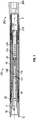
FIG. 1 is a longitudinal cross-section through a bearing assembly incorporating an embodiment of a rotary drive system in accordance with the present disclosure. -
FIG. 2 is an enlarged longitudinal cross-section through the bearing assembly and rotary drive system shown inFIG. 1 . -
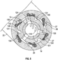
FIG. 3 is a transverse cross-section through the rotary drive system shown inFIGS. 1 and2 . -
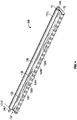
FIG. 4 is an isometric view of one embodiment of one of the gates used in the rotary drive system shown inFIG. 3 . -
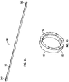
FIG. 4A is an isometric view of a torsion rod for use in conjunction with a gate asFIG. 4 . -
FIG. 4B is an isometric view of a gate preload ring for use in conjunction with torsion rods as inFIG. 4A . -
FIG. 5 is an isometric cross-section through the housing of the rotary drive system shown inFIGS. 1 to 3 . -
FIG. 6 is an isometric cross-section through the rotary drive system shown inFIGS. 1 to 3 , but with the mandrel and rotor not shown. -
FIGS. 7 and8 are cross-sections through the rotary drive system as inFIG. 3 , showing the lobed shaft in different rotational positions relative to the housing. -
FIG. 9 is a longitudinal cross-section through a bearing assembly incorporating an alternative embodiment in which the rotor of the rotary drive system engages the mandrel of bearing section in end-to-end relation. -
FIG. 9A is a longitudinal cross-section through a variant of the bearing assembly inFIG. 9 . -
FIG. 10 is an enlarged sectional detail of one embodiment of a relief valve system for use in conjunction with rotary drive systems in accordance with the present disclosure. -
FIG. 11 is an enlarged sectional detail of a variant of the relief valve shown inFIG. 10 . -
FIG. 12 is a cross-sectional detail of an end-to-end connection between the rotor and mandrel in an alternative embodiment of a rotary drive system in accordance with the present disclosure, using a threaded and splined connector. -
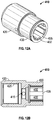
FIGS. 12A and 12B are isometric and cross-sectional views, respectively, of the threaded and splined connector inFIG. 12 . -
FIG. 13 is a longitudinal cross-section through an alternative embodiment of a downhole motor incorporating a concentric rotary drive system in accordance with the present disclosure, in which the bent housing is located below the rotary drive system and the rotary drive system is operatively connected to the motor's bearing section by a drive shaft having a single U-joint. -
FIG. 13A is an enlarged cross-sectional view of the bent housing and drive shaft of the downhole motor inFIG. 13 . -
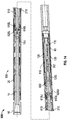
FIG. 14 is a longitudinal cross-section through a further embodiment of a downhole motor incorporating a concentric rotary drive system in accordance with the present disclosure, in which the rotary drive system is connected to a conventional bearing section by means of a conventional drive shaft having two U-joints. - The Figures illustrate various embodiments of downhole motors in accordance with the present disclosure.
FIG. 1 illustrates a bearingassembly 100 comprising afirst embodiment 110 of a concentric rotary drive system connected at its upper end to the lower end of abent housing 200, which incorporates a fixed or adjustablebent sub 210. Although the illustrated bearing assembly incorporates a bent housing, it is to be understood that this is not essential, as the bearing assembly and rotary drive systems in accordance with the present disclosure could alternatively be run without a bent housing (i.e., when drilling a straight or undeviated section of a wellbore). -
Bearing assembly 100 includes anelongate mandrel 10 coaxially disposed within a generallycylindrical housing 20 so as to be rotatable relative thereto, with thelower end 12 ofmandrel 10 projecting from thelower end 22 ofhousing 20 and being adapted for connection to a drill bit or other BHA components below the motor.Mandrel 10 has acentral bore 14 for passage of a working fluid such as a drilling fluid. Theupper end 205 ofbent housing 200 is adapted for connection to the drill string or to other BHA components above the motor. - The primary features of the bearing
assembly 100 androtary drive system 110 inFIG. 1 are illustrated in greater detail inFIGS. 2 and3 .Rotary drive system 110 includes a generally cylindrical central shaft 120 (alternatively referred to as rotor 120) concentrically coupled tomandrel 10 so as to be rotatable therewith, and withinhousing 20. Accordingly, a generallyannular space 40 is formed betweenrotor 120 andhousing 20.Annular space 40 is alternatively referred to herein as a workingfluid space 40.End plates housing 20 and define the upper and lower boundaries of workingfluid space 40.End plates rotor 120 relative tohousing 20. - In the illustrated embodiment,
rotor 120 is concentrically coupled tomandrel 10 by means of a splined connection as shown inFIG. 3 , withsplines 16 projecting from the outer surface ofmandrel 10 engagingmating grooves 122 on the inner surface of the bore ofrotor 120. However,rotor 120 could be co-rotatably coupled tomandrel 10 by other means. By way of non-limiting example only,mandrel 10 androtor 120 could abut each other in end-to-end relation, while being rotatably coupled by a mechanism comprising mating axially-aligned lugs on each component, as in the alternative embodiment shown inFIG. 9 (in which the mating lugs onmandrel 10 androtor 120 are indicated byreference numbers rotatably coupling mandrel 10 androtor 120 in end-to-end relation include threaded connections, splined connections, gear boxes, and clutch mechanisms in accordance with known technologies. - By way of non-limiting example,
FIG. 12 depicts analternative embodiment 400 of a bearing section incorporating a rotary drive system in accordance with the present disclosure, in which a threaded andsplined coupling 410 is used to transfer torque fromrotor 120 tomandrel 10. In this embodiment,rotor 120 is supported by its own set ofradial bearings 440 on both ends of the rotor (only lowerradial bearings 440 are shown inFIG. 12 ). - As shown in
FIGS. 12 ,12A, and 12B ,coupling 410 comprises a lowercylindrical section 420 havinginternal threading 425, and an upper generallycylindrical section 430 the bore of which defineslongitudinal splines 432 andgrooves 435. Upper andlower sections central bore 415 in the transition section between upper andlower sections upper end 10U ofmandrel 10 in this embodiment is provided with external threading 15 engageable withinternal threading 425 inlower section 420 ofcoupling 410. Thelower end 120L ofrotor 120 is formed withsplines 115 engageable withgrooves 435 onupper section 430 ofcoupling 410. - As shown in
FIGS. 1 ,2 ,5 ,7 , and8 ,fluid inlet ports 116 are provided throughmandrel 10 androtor 120 in an upstream region ofrotor 120 to allow fluid flow from mandrel bore 14 into workingfluid space 40, andfluid outlet ports 117 are provided throughrotor 120 andmandrel 10 in a downstream region ofrotor 120 to allow fluid flow from workingfluid space 40 back into mandrel bore 14. Accordingly,rotary drive system 110 can be considered as defining a fluid path through the rotary drive system, extending between a fluid intake zone in anupstream region 14U of mandrel bore 14, throughinlet ports 116 into workingfluid space 40, and out of workingfluid space 40 throughoutlet ports 117 into a fluid exit zone in adownstream region 14D of mandrel bore 14 proximal to thelower end 120L ofrotor 120, from which zone fluid flow can continue within mandrel bore 14 toward the bit. - As best seen in
FIGS. 3 ,5 ,7 , and8 the outer perimeter surface ofrotor 120 defines a
plurality of uniformly-spacedlongitudinal rotor lobes 124. As best seen inFIGS. 3 ,5 ,6 ,7 , and8 , a plurality ofelongate gates 130 are pivotably mounted within respective elongate gate-receivingpockets 26 in theinner surface 24 of the bore ofhousing 20. -
FIG. 4 illustrates one embodiment of agate 130 in accordance with the present disclosure. In this embodiment,gate 130 has ends 131 (which may be designated upper and lower ends 131U and 131L depending on the orientation ofgate 130 in a given embodiment of the drive system) and anelongate blade member 134 with afirst blade surface 135 oriented toward the associatedgate pocket 26. The radially-outer end ofblade member 134 has a longitudinalfree edge 139 configured for substantially fluid-tight contact with the outer surfaces of rotor 120 (including, as the operational case may be, rotor lobes 124).Free edge 139 ofblade member 134 preferably (but not necessarily) has a thickened orbulbous section 136 projecting fromfirst blade surface 135.Thickened section 136 may be continuous or, as shown inFIGS 3-8 , it may form a plurality of spacedprojections 136A extending fromblade surface 135 toward the associatedgate pocket 26, withgaps 136B being formed betweenadjacent projections 136A. - The
inner surface 24 of the bore ofhousing 20 is formed with elongate gate pockets 26 such that aslobed rotor 120 rotates withinhousing 20,rotor lobes 124 will sequentially engagegates 130 and deflect them into their associated gate pockets 26 inhousing 20 so thatrotor lobes 124 can pass by. Eachgate 130 thus pivots between a lowered position (i.e., in contact with or closely adjacent to rotor 120) when located betweenadjacent rotor lobes 124, and a raised (or deflected) position when displaced into its associatedgate pocket 26 by a passingrotor lobe 124. - Optionally,
projections 136A and gate pockets 26 may be configured such thatprojections 136A of a givengate 130 will abut a surface of the associatedgate pocket 26 whengate 130 is maximally deflected intogate pocket 26. Preferably,projections 136A are evenly spaced along the length ofgate 130. In one embodiment, the cumulative length ofgaps 136B, as measured along the length ofgate 130, corresponds to at least 10% of the gate length. In an alternative embodiment, the cumulative length ofgaps 136B corresponds to at least 30% of the gate length. In yet another embodiment, the cumulative length ofgaps 136B corresponds to as much as 90% of the gate length. - In preferred embodiments, each
gate pocket 26 incorporates a debris slot or chamber
27, to accommodate or receive large particulate matter that might be present in the drilling fluid and which might otherwise impede full deflection of the associatedgate 130 intogate pocket 26 by the passingrotor lobes 124. This can be best appreciated with reference toFIG. 3 , in which an exemplary gate denoted byreference character 130A is shown fully deflected into its associated gate pocket 26A. Oversize matter carried by the drilling fluid can temporarily reside withindebris chamber 27A asrotor lobes 124 pass by, rather than becoming lodged behindgate 130A and impeding full deflection ofgate 130A into gate pocket 26A, as might otherwise happen if the gate pockets were configured to closely match the profile ofgates 130. -
FIG. 7 illustrates a variant gate denoted byreference number 130C, having adebris channel 27C formed in its outer face, and there is nodebris chamber 27 formed into thevariant gate pocket 26C associated withgate 130C. - Preferably, each
gate 130 and associatedgate pocket 26 are relatively configured to form at least one gate pocket flow path (denoted bydotted line 141 inFIG. 3 ), such that fluid can flow out ofgate pocket 26 into workingfluid space 40 even whengate 130 is maximally deflected intogate pocket 26. In the embodiment shown inFIG. 3 , gatepocket flow path 141 includes anupstream portion 141U co-extensive withgaps 136B in thickenedsection 136.Gates 130 and gate pockets 26 are configured so that when agate 130 is maximally deflected into its associatedgate pocket 26, the gate's freelongitudinal edge 139 is spaced from alongitudinal wall 143 of the gate pocket to create adownstream portion 141 D of gatepocket flow path 141, in fluid communication with workingfluid space 40. - As best understood with reference to
FIGS. 2 ,3 ,7 , and8 , withgates 130 being biased into substantially fluid-tight contact withrotor 120, workingfluid space 40 betweenrotor 120 andhousing 20 is divided intolongitudinal chambers 140 betweenrotor lobes 124 andadjacent gates 130.Longitudinal chambers 140 are bound at either end byend plates rotary drive system 110 throughinlet ports 116, thus pressurizing (at any given time) one or morelongitudinal chambers 140 and inducing rotation of rotor 120 (andmandrel 10 along with it) relative tohousing 20. Opposite the high pressure side of the lobe, the fluid is directed throughfluid outlet ports 117 and onward through the bit. - As may be appreciated with reference to
FIGS. 7 and8 in particular, the configuration and volume of eachlongitudinal chamber 140 will change asrotor 120 rotates within and relative tohousing 20. For example,FIG. 8 illustrates a first longitudinal chamber denoted byreference character 140A having a comparatively large volume, and a second longitudinal chamber denoted byreference character 140B having a greatly reduced volume as arotor lobe 124B approaches the associatedgate 130B. Accordingly, fluid must be conveyed out ofchambers 140 to prevent the build-up of excessive fluid pressure. This is accomplished in the illustrated embodiments by formingrotor 120 withpressure relief channels 121 to convey drilling fluid fromchambers 140 to fluid outlet ports 117 (as may be seen inFIGS. 3 and5 ). - The pivotability of
gates 130 may be enabled by any suitable means, and embodiments within the scope of the present disclosure are not limited or restricted to the use of any particular pivoting means. To provide one non-limiting example, eachgate 130 may be provided with a longitudinal pin bore 133 generally as shown inFIG. 3 , for receiving elongate pivot pins, the ends of which are rotatably received within pockets or bearings associated withhousing 20. In the specifically illustrated embodiments, however,gates 130 are pivotably retained within cylindrical pivot pockets 25 formed inhousing 20. In the embodiment shown inFIG. 4 , eachgate 130 has an elongate convexly-cylindrical surface 138 which is matingly receivable within a correspondingcylindrical pivot pocket 25 to form a cylindrical pivot interface. In the illustrated embodiment, the cylindrical portions of pivot pockets 25 extend around an arc greater than 180 degrees, such the pivot pockets fully retain the gates without need for pivot pins as such; in effect, the portions ofgates 130 havingcylindrical surfaces 138 function as pivot pins. - Preferably,
gates 130 are provided with biasing means for biasinggates 130 away fromhousing 20 and into substantially sealing contact withrotor 120. Such biasing means could comprise torsion rod springs, torsion coil springs, cam bodies, fluid pressure, or any other suitable mechanical or hydraulic means. In one embodiment, and with particular reference toFIGS. 4 ,4A, and 4B , the biasing means may comprisetorsion rods 50 disposed within pin bores 133 provided ingates 130 as shown inFIG. 3 . Eachtorsion rod 50 has acentral section 52 of circular cross-section extending between upper andlower end sections - In the embodiment shown in
FIG. 4A , this rotational restraint is enabled by forming upper andlower end sections FIG. 4B illustrates agate preload ring 60 having a plurality ofsquare holes 62 corresponding in number to the number ofgates 130 in therotary drive system 110, withsquare holes 62 being sized for mating engagement withupper end section 54U oftorsion rod 50. In the embodiment shown inFIGS. 1 and2 ,preload ring 60 is coaxially fixed tohousing 20 immediately aboveend plate 42U so as to be non-rotatable relative tohousing 20, such that in the assembled drive systemupper end 54U of eachtorsion rod 50, projecting from the upper end of its associated pin bore 133 atupper end 131U of the associatedgate 130, will be matingly disposed within one of thesquare holes 62 ingate preload ring 60. The upper ends oftorsion rods 50 will thus be restrained against rotation relative tohousing 20, but the upper ends oftorsion rods 50 will be unrestrained against rotation within the pin bores 133 of their associatedgates 130 and relative to the upper ends 131 U thereof. - However, as may be understood with reference to
FIG. 4 , the lower ends 54L oftorsion rods 50 will be restrained against rotation relative to the lower ends 131L of their associatedgates 130. In this embodiment,lower end 131L ofgate 130 is fitted with acap member 70 having asquare hole 72 for matingly receiving the squarelower end 54L of atorsion rod 50, thus effectively lockingtorsion rod 50 against rotation relative tolower end 131L ofgate 130. However,lower end 131L ofgate 130 is unrestrained against rotation relative tohousing 20. Accordingly,gates 130 andtorsion rods 50 can be assembled inrotary drive system 110 such that sealing surfaces 137 associated with theouter edges 139 ofgates 130 will initially be closely adjacent to or in contact with the surface ofrotor 120. Optionally,torsion rods 50 may be installed with an initialpre-torque biasing gates 130 againstrotor 120. Pivoting deflection ofgates 130 caused by fluid flow throughrotary drive system 110 will induce torsional strain (or increase any initial torsional strain) intorsion rods 50, thus positively biasinggates 130 towardrotor 120. - The number of
rotor lobes 124 and the number ofgates 130 can vary. Preferably, however, there will always be at least onefluid inlet port 116 and at least onefluid outlet port 117 located betweenadjacent rotor lobes 124 at any given time, and at least onegate 130 sealing between adjacent fluid inlet and outlet ports at any given time. - Torque and speed outputs of
rotary drive system 110 are dependent on the length and
radial height (i.e., gate lift) ofchambers 140. For a given drive system length, a smaller gate lift produces higher rotational speed and lower torque. Conversely, a larger gate lift produces higher torque and lower rotational speed. In preferred embodiments, different configurations ofgates 130 androtor lobes 124, with varying levels of gate lift, can be used to achieve broad torque and speed ranges as may be required for different drilling applications, from low-speed / high-torque performance drilling to high-speed turbine applications. -
Bearing assembly 100 comprises multiple bearings for transferring the various axial and radial loads betweenmandrel 10 andhousing 20 that occur during the drilling process.Thrust bearings radial bearing 104 and 105 transfers radial loads betweenmandrel 10 andhousing 20. In preferred embodiments, the thrust bearings and radial bearings are mud-lubricated PDC (polycrystalline diamond compact) insert bearings, and a small portion of the drilling fluid is diverted through the bearings to provide lubrication and cooling. In other embodiments, other types of mud-lubricated bearings may be used, or one or more of the bearings may be oil-sealed. - In the embodiment shown in
FIG. 2 , radial loads are transferred frommandrel 10 tohousing 20 throughbearing 104, not frommandrel 10 torotor 120. In alternative embodiments, however, radial loads could be transferred throughrotor 120 if desired, by usingrotor 120 itself as a radial bearing in lieu ofradial bearing 104. - In the alternative embodiment shown in
FIG. 9A , the arrangement of the radial and axial bearings is changed such that radial loads are carried bymandrel 10 and preferably not transferred torotor 120. In this embodiment, bearingassembly 100 section comprises a lower radial bearing 301 (analogous to radial bearing 105 inFIG. 2 ) and an additionalradial bearing 303 below the rotary drive assembly, serving the same general function asradial bearing 104 in the embodiment shown inFIG. 2 but in a different location. Another set ofbearings rotor 120 both radially and axially. - In preferred embodiments, no elastomeric dynamic seals are used. Leakage is minimized by maintaining small amounts of clearance between components within
drive system 110. Small amounts of leakage will reduce the overall efficiency of the drive system, but that is acceptable for this application. Efficiency will still equal or exceed that of a Moineau power section. Moreover, with no elastomeric dynamic seals being used, the motor will be suitable for high-temperature/geothermal applications that Moineau power sections cannot withstand. - Notwithstanding the foregoing discussion of thrust bearings and radial bearings in downhole motor bearing sections, it is to be noted that the particular types and arrangements of bearings that may be used in bearing assemblies incorporating rotary drive systems in accordance with the present disclosure are not directly relevant to such rotary drive systems, and do not form part of the broadest embodiments thereof.
-
FIGS. 2 and3 illustrate optional additional features that are beneficial but not essential to rotary drive systems in accordance with the present disclosure. One such optional feature is a flow control mechanism in the form of arelief valve 150 which protects the assembly from excessive torque loads by limiting the amount of pressure that can build up within the rotary drive assembly.Relief valve 150 provides this protection by allowing fluid to bypass the rotary drive system when the fluid pressure exceeds a pre-set pressure, through adownstream bore 154 inrelief valve 150 discharging into mandrel bore 14. Therelief valve 150 illustrated inFIGS. 2 and3 is only one non-limiting example of a device that may optionally be used to limit pressure build-up in rotary drive systems in accordance with the present disclosure. -
FIG. 10 illustrates one embodiment of a mechanicalrelief valve system 350 which can be used to limit differential pressure across the rotary drive system by bypassing flow throughrotor 120. This same mechanism could also be used as a speed control to limit RPM to a pre-set limit.Relief valve system 350 works such that fluid flow F enters the mechanism from right to left (as viewed with reference toFIG. 10 ), withrelief valve system 350 sealing off flow so that it is forced through the rotary drive mechanism's fluid inlet and outlet ports and gates (as generally described previously herein). When the differential pressure acrossrelief valve system 350 reaches a pre-set limit, avalve 325, biased by aspring 321, will move to the left allowing a portion of the flow to bypass the rotary drive system through the center ofrotor 120.Valve 325 could alternatively be biased mechanically or hydraulically. -
FIG. 11 illustrates an alternative mechanicalrelief valve assembly 350A, which is operable in largely the same manner as described above with respect torelief valve system 350 shown inFIG. 10 .Relief valve assembly 350A works such that flow fluid enters the device from right to left, withrelief valve assembly 350A sealing off flow so that it is forced through the rotary drive mechanism's fluid inlet and exit ports and gates. When differential pressure reaches a pre-set limit,valve 325A, biased by aspring 321A, will move to the left allowing a portion of the flow to bypass the rotary drive system through the center ofrotor 120.Valve 325A could alternatively be biased mechanically or hydraulically. - Alternatively, a mechanism similar to the two-speed motor disclosed in
U.S. Patent No. 7,523,792 (which is hereby incorporated by reference in its entirety) could also be used to allow an operator two different speed ranges at a given flow rate using the same rotary drive geometry. This would be accomplished by turning fluid flow on and off. Alternatively, this could be accomplished by an electronically-controlled valve system. This valve system could react to drilling conditions such as vibration, bit whirl, and stick slip, and/or it could be communicated with, either from surface or from a downhole signal generator, to change the amount of fluid bypass throughrotor 120 in the rotary drive system. - Notwithstanding the preceding discussion, it is not essential to limit differential pressure across rotary drive systems in accordance with the present disclosure. Alternative embodiments may use other forms of flow control such as, by way of non-limiting example, a solid plate (either integral with either the mandrel or the rotor, or a separately-sealed component) to separate flow between the fluid inlet and outlet ports. Alternative embodiments may use a nozzle to continuously bypass a portion of the flow through the rotor in order to reduce the rotary speed of the drive section. Alternative embodiments may also use a burst disc to separate flow between inlet and outlet ports. In the event that the burst disc capacity is exceeded and the disc ruptures, all or a portion of the flow would subsequently bypass through the rotor. Alternative embodiments may incorporate a flow diverter as described in
U.S. Patent No. 6,976,832 to evenly distribute fluid intake and outlet flow along all or a portion of the length of the drive section. - Alternative embodiments may relieve pressure by bypassing drilling fluid directly to the annulus between
housing 20 and the wellbore, or, alternatively, betweenbent housing 200 and the wellbore. - Another optional feature, illustrated in
FIG. 2 ), is the use of sealingplates 160, which comprise mating wear-resistant surfaces that leak only a small amount of drilling fluid, so that nearly all of the fluid diverted to lubricate and cool the bearings is directed back through the mandrel and onward through the bit. Rotary seals could be used in place of sealingplates 160; alternatively, a flow restrictor of conventional type or diamond material (e.g., PDC) could be used. - In an alternative embodiment, the design could be changed to allow rotation of the stator section (
housing 20 with gates 130) relative torotor 120 andmandrel 10. This could be achieved, for example, by modifying the embodiments shown inFIGS. 1 ,2 ,9 , and9A . In such variant configurations,mandrel 10 would attach to the drill string, which would reverse the fluid flow path; i.e., whereas the fluid flow path F as shown inFIGS. 1 ,2 , and9 , is from right to left, the fluid flow path in the variant configurations would be from left to right, with the fluid inlet and outlet ports being suitably configured for this reversed fluid flow path. Having reference toFIGS. 2 and9 , this could necessitate design changes as follows: - First, the bent sub could be moved to the left (i.e., lower) side of the mandrel.
- A suitable bit box sub would need to be added in place of the
housing 200 to allow connection to the drill bit (alternatively, this connection could be a pin connection). - The bypass valves would also need to be "flipped" to allow flow to bypass from left to right.
- It will be readily apparent to those skilled in the art that driveshafts / clutches, additional stages in series or parallel, inlet and outlet ports, gate orientation, and bearings could be moved above or below the power section when holding the mandrel stationary and allowing the stator section (housing) to rotate.
- Alternative embodiments may use rotary drive systems generally as disclosed in any of
U.S. Patents No. 6,280,169 ,No. 6,468,061 , andNo. 6,939,117 , in combination with similar coupling means within the drilling motor, and similar arrangements of bearings. These systems utilize similar principles of operation, but with alternative forms of the gate/lobe system, such as radially-actuating gates as opposed to pivoting gates, or pivoting gates connected to the mandrel and engageable by lobes formed on the bearing section housing. - For example, referring to
FIG. 3 ,housing 20,gates 130, andtorsion rods 50 could be replaced with the necessary components from the system of radially-actuating gates illustrated in Figure 33 inU.S. Patent No. 6,280,169 . As another example, referring again toFIG. 3 ,housing 20,gates 130,torsion rods 50, androtor 120 could be replaced with the necessary components from the system illustrated inFigure 9A inU.S. Patent No. 6,939,117 , wherein the lobes are fixed to the housing and the gates are mounted about the outer surface of the mandrel. - Having regard to the preceding discussion, it is to be appreciated that concentric rotary drive systems in accordance with the present disclosure are not limited to embodiments in which the gates are mounted to the housing (and deflectable into gate pockets formed in the housing) and in which gate-actuating lobes are incorporated into a mandrel concentrically rotatable within the housing. The present disclosure also extends to alternative embodiments having gates mounted to the mandrel (and deflectable into gate pockets formed in the mandrel) and in which gate-actuating lobes are incorporated into the housing, and also to embodiments incorporating radially-actuating gates.
- Accordingly, one category of concentric rotary drive systems in accordance with the present disclosure can be broadly described as comprising:
- a first body and a second body, with a selected one of the bodies being coaxially disposed inside the other body to define a working fluid space therebetween, and with the second body being rotatable relative to the first body about a rotational axis;
- at least one gate pivotably supported by a selected one of the first and second bodies, and pivotable about a pivot axis parallel to the rotational axis; and
- at least one lobe provided on the body not supporting the at least one gate, with the at least one lobe being configured to contact the at least one gate during rotation of the second body.
- Therefore, the component referenced previously in this Detailed Description as "
housing 20" could, in alternative embodiments, be characterized as either the "first body" or the "second body", with the component referenced asrotor 120 being characterized as either the "second body" or the "first body". It will also be appreciated that in certain alternative embodiments the rotary drive system could be configured such that the selected body coaxially disposed within the other body could be non-rotating relative to the drill string; i.e., the other (or outer) body would be rotatable relative to the "selected" (i.e., inner) body. Persons skilled in the art will appreciate that such alternative embodiments can be put in to practice on the basis of the present disclosure, modified as a given embodiment may require having reference to the information provided herein and common general knowledge in the art, and without need for specific illustration, significant experimentation, or inventive input. -
FIGS. 13 and13A illustrate analternative embodiment 500 of a downhole motor incorporating a concentricrotary drive system 110 in accordance with the present disclosure. In this variant embodiment, thebent sub 210 is located belowrotary drive system 110, androtary drive system 110 is operatively connected to the motor'sbearing section 100 by adrive shaft 510. Becauserotary drive system 110 does not operate eccentrically like a conventional downhole motor drive section,drive shaft 510 requires a universal joint (U-joint) 515 only at itslower end 510L, where it engages a lowerdrive shaft housing 520 coupled to theupper end 10U ofmandrel 10 ofbearing section 100, adjacent tobent sub 210. At itsupper end 510U,drive shaft 510 is connected rigidly and coaxially to thelower end 120L ofrotor 120, by any functionally suitable means. -
FIG. 14 illustrates a furtheralternative embodiment 600 of a downhole motor incorporating a concentric rotary drive system in accordance with the present disclosure. In this embodiment,rotary drive system 110 is connected to aconventional bearing section 100 by means of aconventional drive shaft 610 having upper andlower U-joints Lower U-joint 615L engages a lowerdrive shaft housing 620L coupled to theupper end 10U ofmandrel 10, similar to the embodiment shown inFIGS. 13 and13A . In this embodiment,bent sub 210 is located approximately midway betweenU-joints -
Upper U-joint 615U engages an upperdrive shaft housing 620U which in turn is connected rigidly and coaxially tolower end 120L ofrotor 120. In the specific embodiment shown inFIG. 14 , upperdrive shaft housing 620U connects torotor 120 by means of a threaded andsplined coupling 650 generally similar tocoupling 410 shown inFIGS. 12 ,12A, and 12B . However, this is by way of non-limiting example only, and the connection between upperdrive shaft housing 620U androtor 120 could alternatively be effected by any functionally suitable means. - The embodiments of
rotary drive system 110 illustrated in the Figures may be referred to as a single-stage drive system; i.e., having a single set ofgates 130 associated with alobed rotor 120. However, alternative embodiments ofrotary drive system 110 may incorporate multiple-stage drives as necessary or desirable to achieve required performance. - For embodiments having multiple power sections aligned in series, the power sections can be coupled by means of a splined and/or threaded connection, such as, for example, the connection illustrated in
FIGS. 12 ,12A, and 12B . Alternatively the power sections could be coupled by means of an arrangement as in the exemplary embodiment inFIG. 9 , withcomponent 129 being used on the right end of the rotor to connect to another power section of similar type, or to connect a power section as disclosed herein to a conventional Moineau or turbine-type drive system. This arrangement could also use a driveshaft between the rotary drive system and a Moineau or turbine drive system. This arrangement would allow for increased torque output, but with higher differential pressure than using just one power section. - In further alternative embodiments, a gear box could be incorporated into the coupling between two power sections coupled in series.
- For embodiments having multiple power sections arranged to be run in parallel, two power sections as disclosed herein could be run end to end and coupled by means of splined, threaded, or clutch-type engagement as stated above. A flow diverter would be needed to send a portion of the flow past the first stage to the second stage only and then on to the bit. This flow diverter would allow flow to enter either the first stage or the second stage only, and then exit to the bit without entering the other stage. This arrangement would allow increased torque output at the same differential pressure across the rotary drive system.
- It will be readily appreciated by those skilled in the art that various modifications to embodiments in accordance with the present disclosure may be devised without departing from the scope and teaching of the present teachings, including modifications which may use equivalent structures or materials hereafter conceived or developed. It is to be especially understood that the scope of the present disclosure is not intended to be limited to described or illustrated embodiments, and that the substitution of a variant of a claimed element or feature, without any substantial resultant change in functionality, will not constitute a departure from the scope of the disclosure. It is also to be appreciated that the different teachings of the embodiments described and discussed herein may be employed separately or in any suitable combination to produce desired results.
- In this patent document, any form of the word "comprise" is to be understood in its non-limiting sense to mean that any item following such word is included, but items not specifically mentioned are not excluded. A reference to an element by the indefinite article "a" does not exclude the possibility that more than one of the element is present, unless the context clearly requires that there be one and only one such element.
- Any use of any form of the terms "connect", "engage", "couple", "attach", or any other term describing an interaction between elements is not meant to limit the interaction to direct interaction between the subject elements, and may also include indirect interaction between the elements such as through secondary or intermediary structure.
- Relational terms such as "parallel", "concentric", and "coaxial" are not intended to denote or require absolute mathematical or geometrical precision. Accordingly, such terms are to be understood as denoting or requiring substantial precision only (e.g., "substantially parallel") unless the context clearly requires otherwise.
- Wherever used in this document, the terms "typical" and "typically" are to be interpreted in the sense of representative of common usage or practice, and are not to be interpreted as implying essentiality or invariability.
- The following numbered clauses on
pages 26 to 29 of the present description correspond to the claims of European patent application no.EP13721235.3 EP13721235.3 -
- Clause 1. A drilling motor comprising:
- (a) a bearing assembly comprising: a generally cylindrical housing having an upper end and a lower end; a generally cylindrical mandrel having an upper end, a lower end, and a longitudinal bore, said mandrel being coaxially disposed within the housing so as to be rotatable relative thereto about a rotational axis; radial bearing means disposed in an annular space between the housing and the mandrel; and thrust bearing means disposed in an annular space between the housing and the mandrel;
- (b) a generally cylindrical rotor having an upper end, a lower end, and a longitudinal bore, said rotor being coaxially disposed within the housing so as to define a generally annular working fluid space therebetween, with said rotor operatively engaging the mandrel so as to be rotatable therewith;
- (c) a plurality of elongate gates;
- (d) at least one axially-oriented lobe engageable with the gates during relative rotation between the rotor and the housing;
- (e) one or more fluid inlets allowing fluid flow from an upper region of the rotor bore into the working fluid space; and
- (f) one or more fluid outlets allowing fluid flow out of the working fluid space into a lower region of the rotor bore;
- Clause 2. A drilling motor as in clause 1 wherein the gates are supported by the housing and pivotable about a pivot axis parallel to the rotational axis.
- Clause 3. A drilling motor as in clause 1 wherein the gates are supported by the rotor and pivotable about a pivot axis parallel to the rotational axis.
- Clause 4. A drilling motor as in clause 1 wherein the gates are radially-actuating and supported by the housing.
- Clause 5. A drilling motor as in clause 1 wherein the gates are radially-actuating and supported by the rotor.
- Clause 6. A drilling motor as in clause 1, further comprising biasing means associated with the gates.
- Clause 7. A drilling motor as in clause 1 wherein the housing incorporates a bent sub located above the rotor.
- Clause 8. A drilling motor as in clause 1 wherein the mandrel engages the rotor so as to be coaxially rotatable therewith.
- Clause 9. A drilling motor as in clause 8, wherein the mandrel engages the rotor by means of a splined connection, with an upper portion of the mandrel coaxially disposed within the bore of the rotor.
-
Clause 10. A drilling motor as in clause 8, wherein the upper end of the mandrel engages the lower end of the rotor by means of respective mating lugs provided on the upper end of the mandrel and the lower end of the rotor. - Clause 11. A drilling motor as in clause 8, wherein the mandrel engages the rotor by means of a clutch mechanism disposed between the upper end of the mandrel and the lower end of the rotor.
-
Clause 12. A drilling motor as in clause 8, wherein the mandrel engages the rotor by means of a gear box disposed between the upper end of the mandrel and the lower end of the rotor. - Clause 13. A drilling motor as in clause 8, wherein the mandrel engages the rotor by means of a generally cylindrical coupling having a lower section with internal threading matingly engageable with external threading on the upper end of the mandrel, and having an upper section with internal splines matingly engageable with external splines on the lower end of the rotor.
-
Clause 14. A drilling motor as in clause 1 wherein the mandrel engages the rotor by means of a drive shaft, said drive shaft having an upper end rigidly and coaxially engaging the lower end of the rotor, and a lower end incorporating a universal joint which engages a drive shaft housing coupled to the upper end of the mandrel. -
Clause 15. A drilling motor as inclause 14 wherein the housing incorporates a bent sub positioned below the lower end of the rotor. -
Clause 16. A drilling motor as inclause 15 wherein the bent sub is positioned proximal to the universal joint. - Clause 17. A drilling motor as in clause 1 wherein the mandrel engages the rotor by means of a drive shaft, said drive shaft having an upper end incorporating an upper universal joint engaging an upper drive shaft housing coupled to the lower end of the rotor, and a lower end incorporating a lower universal joint which engages a drive shaft housing coupled to the upper end of the mandrel.
- Clause 18. A drilling motor as in clause 17 wherein the housing incorporates a bent sub positioned between the upper and lower universal joints.
-
Clause 19. A drilling motor as in clause 1 wherein the radial bearing means is adapted to transfer radial loads from the mandrel to the housing through the rotor. -
Clause 20. A drilling motor as inclause 19 wherein the rotor is adapted to serve as a radial bearing. - Clause 21. A drilling motor as in clause 1, further comprising flow control means, for altering the characteristics of fluid flow through the motor to regulate the rotational speed of the motor.
-
Clause 22. A drilling motor as in clause 21, wherein the flow control means is configured to allow fluid to bypass the working fluid space when the pressure differential across the working fluid space exceeds a pre-set value. - Clause 23. A drilling motor as in clause 21, wherein the flow control means comprises a relief valve coaxially disposed within the rotor.
-
Clause 24. A drilling motor as in clause 21, wherein the flow control means comprises a plate integral with a selected one of the mandrel and the rotor, and positioned to separate flow between the fluid inlets and the fluid outlets. -
Clause 25. A drilling motor as in clause 21, wherein the flow control means comprises a nozzle for continuously bypassing a portion of the fluid flow through the rotor. -
Clause 26. A drilling motor as in clause 21, wherein the flow control means comprises a burst disc positioned to separate flow between the fluid inlets and the fluid outlets. -
Clause 27. A drilling motor as in clause 21, wherein the flow control means comprises means for diverting fluid to the exterior of the housing.
Claims (15)
- A system, comprising:a bearing assembly, including an elongate mandrel, the mandrel having a central mandrel axis, a first end configured to couple to a drill bit, and a second end opposite the first end;a rotary drive system coupled to the bearing assembly and including:a housing;a rotor rotatably disposed within the housing;an annular space between the rotor and the housing;wherein the rotor includes a central rotor axis, a first end, a second end opposite the first end, a rotor bore extending axially from the first end to the second end, a plurality of fluid inlet ports extending radially from the rotor bore to the annular space, and a plurality of fluid outlet ports extending radially from the annular space to the rotor bore;wherein the first end of the rotor is coupled to the second end of the mandrel;a plurality of elongate gates disposed within the annular space, each of the plurality of elongate gates configured to engage the rotor and the housing; anda plurality of longitudinal lobes extending radially within the annular space;wherein the plurality of longitudinal lobes and the plurality of elongate gates divide the annular space into a plurality of circumferentially adjacent, axially extending longitudinal chambers;
a first fluid flow path defined by the annular space between the plurality of inlet ports and the plurality of outlet ports;
wherein the rotor is configured to rotate relative to the housing when a fluid is circulated along the first fluid flow path;
wherein the mandrel and the rotor are coaxially aligned. - The system of claim 1, wherein the second end of the mandrel is directly connected to the first end of the rotor.
- The system of claim 1 or 2, wherein the second end of the mandrel is directly connected to the first end of the rotor with one of a splined connection, a threaded connection, and corresponding mating lugs.
- The system of any of claims 1 to 3, wherein the second end of the mandrel is coupled to the first end of the rotor with a coupling member.
- The system of claim 4, wherein the coupling member includes:a first end;a second end opposite the first end;internal threading disposed on the first end; andsplines disposed on the second end;wherein the second end of the mandrel includes external threading that is configured to
engage with the internal threading on the first end of the coupling member; and wherein the first end of the rotor includes splines that are configured to engage with the
splines disposed on the second end of the coupling member. - The system of any of claims 1 to 5, further comprising a bent housing, wherein the rotary drive system is axially disposed between the bearing assembly and the bent housing.
- The system of any of claims 1 to 6, wherein each of the plurality of elongate gates is pivotally coupled to the housing and each is configured to pivot about a pivot axis that is parallel to and radially spaced from the rotor axis.
- The system of any of claims 1 to 7, wherein each of the plurality of elongate gates has a free edge and wherein the free edge is biased into engagement with the rotor.
- The system of any of claims 1 to 8, further comprising: a bent housing coupled to the an end of the housing such that the rotary drive system is disposed between the bent housing and the bearing assembly.
- The system of any of claims 1 to 9, wherein the mandrel is rotatably disposed within the housing.
- The system of claim 10, wherein the bearing assembly further includes a first radial bearing and a second radial bearing;
wherein the first radial bearing and the second radial bearing are each configured to support radially directed loads with respect to the central mandrel axis; and
wherein the first radial bearing is proximate the first end of the rotor and the second radial bearing is proximate the second end of the rotor. - The system of any of claims 1 to 11, wherein each and every one of the fluid inlet ports is axially spaced from each and every one of the fluid outlet ports; and
wherein the system further comprises a flow control assembly disposed in the rotor bore and configured to control the flow of the fluid along the first flow path to regulate one of a rotational speed of the rotor or a torque applied to the rotor. - The system of claim 12, further comprising:a second fluid flow path defined by the rotor bore between the plurality of inlet ports and the plurality of outlet ports;wherein the flow control assembly selectively diverts a portion of the fluid to the second flow path when a differential pressure between the plurality of inlet ports and the plurality of outlet ports reaches a pre-determined value.
- The system of claim 13, wherein the flow control assembly comprises a relief valve.
- The system of claim 12, wherein the flow control assembly is axially disposed between the plurality of fluid inlet ports and the plurality of fluid outlet ports.
Applications Claiming Priority (3)
| Application Number | Priority Date | Filing Date | Title |
|---|---|---|---|
| US201261639762P | 2012-04-27 | 2012-04-27 | |
| PCT/US2013/038446 WO2013163565A2 (en) | 2012-04-27 | 2013-04-26 | Downhole motor with concentric rotary drive system |
| EP13721235.3A EP2841674B1 (en) | 2012-04-27 | 2013-04-26 | Downhole motor with concentric rotary drive system |
Related Parent Applications (2)
| Application Number | Title | Priority Date | Filing Date |
|---|---|---|---|
| EP13721235.3A Division EP2841674B1 (en) | 2012-04-27 | 2013-04-26 | Downhole motor with concentric rotary drive system |
| EP13721235.3A Division-Into EP2841674B1 (en) | 2012-04-27 | 2013-04-26 | Downhole motor with concentric rotary drive system |
Publications (2)
| Publication Number | Publication Date |
|---|---|
| EP3184727A1 true EP3184727A1 (en) | 2017-06-28 |
| EP3184727B1 EP3184727B1 (en) | 2022-01-19 |
Family
ID=48325950
Family Applications (3)
| Application Number | Title | Priority Date | Filing Date |
|---|---|---|---|
| EP13780628.7A Not-in-force EP2841675B1 (en) | 2012-04-27 | 2013-04-26 | Downhole motor with concentric rotary drive system |
| EP13721235.3A Active EP2841674B1 (en) | 2012-04-27 | 2013-04-26 | Downhole motor with concentric rotary drive system |
| EP16190585.6A Active EP3184727B1 (en) | 2012-04-27 | 2013-04-26 | Downhole motor with concentric rotary drive system |
Family Applications Before (2)
| Application Number | Title | Priority Date | Filing Date |
|---|---|---|---|
| EP13780628.7A Not-in-force EP2841675B1 (en) | 2012-04-27 | 2013-04-26 | Downhole motor with concentric rotary drive system |
| EP13721235.3A Active EP2841674B1 (en) | 2012-04-27 | 2013-04-26 | Downhole motor with concentric rotary drive system |
Country Status (12)
| Country | Link |
|---|---|
| US (2) | US9574401B2 (en) |
| EP (3) | EP2841675B1 (en) |
| CN (1) | CN104246106B (en) |
| AU (3) | AU2013251429B2 (en) |
| BR (1) | BR112014026417A2 (en) |
| CA (2) | CA2869664C (en) |
| DK (1) | DK2841674T3 (en) |
| MX (1) | MX356117B (en) |
| MY (1) | MY171775A (en) |
| NO (1) | NO2811160T3 (en) |
| RU (1) | RU2626476C2 (en) |
| WO (2) | WO2013163565A2 (en) |
Cited By (1)
| Publication number | Priority date | Publication date | Assignee | Title |
|---|---|---|---|---|
| CN110657057A (en) * | 2019-10-28 | 2020-01-07 | 重庆理工大学 | A Offset Torque Turbine With Arc Blade Rotation |
Families Citing this family (22)
| Publication number | Priority date | Publication date | Assignee | Title |
|---|---|---|---|---|
| BR112015012280A2 (en) * | 2012-12-28 | 2017-07-11 | Halliburton Energy Services Inc | mitigation of piston effects with oscillation and pistoning through the drilling motor |
| MX2016001935A (en) | 2013-08-12 | 2016-09-06 | Greystone Tech Pty Ltd | A concentric rotary fluid machine. |
| CA3020769A1 (en) | 2016-04-14 | 2017-10-19 | Monashee Pumps Inc. | Rotary drive |
| US11149497B2 (en) * | 2016-10-24 | 2021-10-19 | Rival Downhole Tools Lc | Drilling motor with bypass and method |
| CA3285326A1 (en) * | 2017-03-06 | 2025-10-30 | Charles Abernethy Anderson | Torque generator |
| CN107060637A (en) * | 2017-03-15 | 2017-08-18 | 吉林大学 | A kind of slide block type mud motor |
| AU2018243929B2 (en) | 2017-03-28 | 2022-07-07 | National Oilwell Varco, LP. | Valves for actuating downhole shock tools in connection with concentric drive systems |
| WO2018194575A1 (en) * | 2017-04-19 | 2018-10-25 | Halliburton Energy Services, Inc. | Adjustable modulated agitator |
| EP3399134B1 (en) | 2017-05-01 | 2023-11-08 | Vermeer Manufacturing Company | Dual rod directional drilling system |
| CN109869105B (en) * | 2017-12-01 | 2023-07-21 | 中石化石油工程技术服务有限公司 | A kind of drilling system and drilling method thereof |
| US11543049B2 (en) | 2018-01-05 | 2023-01-03 | Halliburton Energy Services, Inc. | Density-based fluid flow control devices |
| EP4647576A3 (en) * | 2018-04-27 | 2026-01-07 | National Oilwell Varco, L.P. | Wired downhole adjustable mud motors |
| US11180962B2 (en) | 2018-11-26 | 2021-11-23 | Vermeer Manufacturing Company | Dual rod directional drilling system |
| CN109505728B (en) * | 2018-12-28 | 2024-07-30 | 中国地质大学(北京) | Dynamic pushing type rotary motor |
| WO2020186004A1 (en) | 2019-03-14 | 2020-09-17 | Vermeer Manufacturing Company | Rod coupler and coupled rod assembly |
| GB202002686D0 (en) * | 2020-02-26 | 2020-04-08 | Faaborg Uk Ltd | Drill motor |
| US11753901B2 (en) | 2020-03-05 | 2023-09-12 | Thru Tubing Solutions, Inc. | Fluid pulse generation in subterranean wells |
| WO2021202426A1 (en) * | 2020-03-30 | 2021-10-07 | Thru Tubing Solutions, Inc. | Fluid pulse generation in subterranean wells |
| CN111550361B (en) * | 2020-06-28 | 2022-03-18 | 河北中清永晟石油科技有限公司 | Novel positive displacement is electricity generation in pit device and contains its novel oil field water injection system |
| CN113217267B (en) * | 2021-06-08 | 2022-02-11 | 中国地质大学(北京) | All-metal high-temperature-resistant cycloid type downhole motor |
| CN114352241B (en) * | 2022-01-19 | 2023-05-23 | 中国石油大学(华东) | Turbine pump integrated double-channel lifting pump |
| CN114576159B (en) * | 2022-03-15 | 2024-05-14 | 淄博市博山科海机械有限公司 | High-lift leakage-free shielding turbine pump |
Citations (1)
| Publication number | Priority date | Publication date | Assignee | Title |
|---|---|---|---|---|
| US6939117B2 (en) * | 1999-12-21 | 2005-09-06 | Merlin Corporation Pty Ltd | Rotary apparatus |
Family Cites Families (12)
| Publication number | Priority date | Publication date | Assignee | Title |
|---|---|---|---|---|
| SU737615A1 (en) * | 1978-02-20 | 1980-05-30 | Всесоюзный Ордена Трудового Красного Знамени Научно-Исследовательский Институт Буровой Техники | Clutch for connecting rotor with stator in bottom-hole motor |
| GB2055927A (en) * | 1979-08-10 | 1981-03-11 | Eng Enterpr | Wellbore drilling tool |
| SU1218195A1 (en) * | 1984-05-18 | 1986-03-15 | Предприятие П/Я А-1264 | Jaw overrunning clutch |
| US4772185A (en) * | 1985-11-27 | 1988-09-20 | Barmag Ag | Rotary vane pump having a plurality of inlet and outlet slots in a rotating sleeve |
| GB9102320D0 (en) * | 1991-02-02 | 1991-03-20 | Roe John R N | Down-hole wing motor |
| DE69504028T2 (en) * | 1994-01-13 | 1999-02-04 | Gary Lawrence Humble Tex. Harris | DRILL HOLE MOTOR FOR DRILLING DEVICES |
| AUPO292496A0 (en) | 1996-10-11 | 1996-11-07 | Merlin Corporation Pty Ltd | A rotary machine |
| CA2219062C (en) * | 1996-12-04 | 2001-12-25 | Siegfried A. Eisenmann | Infinitely variable ring gear pump |
| NL1007613C2 (en) * | 1997-10-21 | 1999-04-23 | Grup Ir Arnold Willem Josephus | Vibration-free roller blade motor and roller blade pump. |
| US6976832B1 (en) * | 1999-05-31 | 2005-12-20 | Merlin Corporation Pty. Ltd. | Fluid rotary machine |
| US7523792B2 (en) | 2005-04-30 | 2009-04-28 | National Oilwell, Inc. | Method and apparatus for shifting speeds in a fluid-actuated motor |
| CN103410436B (en) * | 2013-08-23 | 2015-06-17 | 中煤科工集团重庆研究院有限公司 | Bottom motor drive shaft assembly of anti-blowout anti-backwater hole |
-
2013
- 2013-04-26 CA CA2869664A patent/CA2869664C/en active Active
- 2013-04-26 US US14/396,578 patent/US9574401B2/en active Active
- 2013-04-26 BR BR112014026417A patent/BR112014026417A2/en active Search and Examination
- 2013-04-26 AU AU2013251429A patent/AU2013251429B2/en active Active
- 2013-04-26 CN CN201380022356.9A patent/CN104246106B/en active Active
- 2013-04-26 WO PCT/US2013/038446 patent/WO2013163565A2/en not_active Ceased
- 2013-04-26 MY MYPI2014703028A patent/MY171775A/en unknown
- 2013-04-26 US US14/391,312 patent/US9771757B2/en active Active
- 2013-04-26 AU AU2013252493A patent/AU2013252493B2/en active Active
- 2013-04-26 EP EP13780628.7A patent/EP2841675B1/en not_active Not-in-force
- 2013-04-26 EP EP13721235.3A patent/EP2841674B1/en active Active
- 2013-04-26 EP EP16190585.6A patent/EP3184727B1/en active Active
- 2013-04-26 CA CA2871258A patent/CA2871258C/en active Active
- 2013-04-26 MX MX2014012853A patent/MX356117B/en active IP Right Grant
- 2013-04-26 RU RU2014145161A patent/RU2626476C2/en active
- 2013-04-26 DK DK13721235.3T patent/DK2841674T3/en active
- 2013-04-26 WO PCT/AU2013/000432 patent/WO2013159153A1/en not_active Ceased
-
2014
- 2014-06-02 NO NO14170720A patent/NO2811160T3/no unknown
-
2017
- 2017-04-07 AU AU2017202308A patent/AU2017202308B2/en active Active
Patent Citations (1)
| Publication number | Priority date | Publication date | Assignee | Title |
|---|---|---|---|---|
| US6939117B2 (en) * | 1999-12-21 | 2005-09-06 | Merlin Corporation Pty Ltd | Rotary apparatus |
Cited By (2)
| Publication number | Priority date | Publication date | Assignee | Title |
|---|---|---|---|---|
| CN110657057A (en) * | 2019-10-28 | 2020-01-07 | 重庆理工大学 | A Offset Torque Turbine With Arc Blade Rotation |
| CN110657057B (en) * | 2019-10-28 | 2020-09-01 | 重庆理工大学 | A Offset Torque Turbine With Arc Blade Rotation |
Also Published As
Similar Documents
| Publication | Publication Date | Title |
|---|---|---|
| EP3184727B1 (en) | Downhole motor with concentric rotary drive system | |
| CN113802984B (en) | Elbow adjustment assembly for downhole mud motor | |
| CA2847474C (en) | Drive shaft assembly for a downhole motor | |
| EP3169863B1 (en) | Universal driveshaft assembly | |
| US11629557B2 (en) | Hybrid bearing assemblies for downhole motors | |
| US10590705B2 (en) | Impact-driven downhole motors | |
| EP4051861A1 (en) | Downhole adjustable bend assemblies | |
| RU2441125C2 (en) | Regulator of downhole hydraulic engine skewness | |
| Maurer et al. | Downhole drilling motors: technical review. Final report |
Legal Events
| Date | Code | Title | Description |
|---|---|---|---|
| PUAI | Public reference made under article 153(3) epc to a published international application that has entered the european phase |
Free format text: ORIGINAL CODE: 0009012 |
|
| STAA | Information on the status of an ep patent application or granted ep patent |
Free format text: STATUS: THE APPLICATION HAS BEEN PUBLISHED |
|
| AC | Divisional application: reference to earlier application |
Ref document number: 2841674 Country of ref document: EP Kind code of ref document: P |
|
| AK | Designated contracting states |
Kind code of ref document: A1 Designated state(s): AL AT BE BG CH CY CZ DE DK EE ES FI FR GB GR HR HU IE IS IT LI LT LU LV MC MK MT NL NO PL PT RO RS SE SI SK SM TR |
|
| AX | Request for extension of the european patent |
Extension state: BA ME |
|
| STAA | Information on the status of an ep patent application or granted ep patent |
Free format text: STATUS: REQUEST FOR EXAMINATION WAS MADE |
|
| 17P | Request for examination filed |
Effective date: 20171205 |
|
| RBV | Designated contracting states (corrected) |
Designated state(s): AL AT BE BG CH CY CZ DE DK EE ES FI FR GB GR HR HU IE IS IT LI LT LU LV MC MK MT NL NO PL PT RO RS SE SI SK SM TR |
|
| STAA | Information on the status of an ep patent application or granted ep patent |
Free format text: STATUS: EXAMINATION IS IN PROGRESS |
|
| 17Q | First examination report despatched |
Effective date: 20180426 |
|
| GRAP | Despatch of communication of intention to grant a patent |
Free format text: ORIGINAL CODE: EPIDOSNIGR1 |
|
| STAA | Information on the status of an ep patent application or granted ep patent |
Free format text: STATUS: GRANT OF PATENT IS INTENDED |
|
| INTG | Intention to grant announced |
Effective date: 20210811 |
|
| GRAS | Grant fee paid |
Free format text: ORIGINAL CODE: EPIDOSNIGR3 |
|
| GRAA | (expected) grant |
Free format text: ORIGINAL CODE: 0009210 |
|
| STAA | Information on the status of an ep patent application or granted ep patent |
Free format text: STATUS: THE PATENT HAS BEEN GRANTED |
|
| AC | Divisional application: reference to earlier application |
Ref document number: 2841674 Country of ref document: EP Kind code of ref document: P |
|
| AK | Designated contracting states |
Kind code of ref document: B1 Designated state(s): AL AT BE BG CH CY CZ DE DK EE ES FI FR GB GR HR HU IE IS IT LI LT LU LV MC MK MT NL NO PL PT RO RS SE SI SK SM TR |
|
| REG | Reference to a national code |
Ref country code: GB Ref legal event code: FG4D |
|
| REG | Reference to a national code |
Ref country code: CH Ref legal event code: EP |
|
| REG | Reference to a national code |
Ref country code: DE Ref legal event code: R096 Ref document number: 602013080755 Country of ref document: DE |
|
| REG | Reference to a national code |
Ref country code: AT Ref legal event code: REF Ref document number: 1463905 Country of ref document: AT Kind code of ref document: T Effective date: 20220215 |
|
| REG | Reference to a national code |
Ref country code: IE Ref legal event code: FG4D |
|
| REG | Reference to a national code |
Ref country code: LT Ref legal event code: MG9D |
|
| REG | Reference to a national code |
Ref country code: NL Ref legal event code: MP Effective date: 20220119 |
|
| REG | Reference to a national code |
Ref country code: NO Ref legal event code: T2 Effective date: 20220119 |
|
| PGFP | Annual fee paid to national office [announced via postgrant information from national office to epo] |
Ref country code: NL Payment date: 20220314 Year of fee payment: 10 Ref country code: FR Payment date: 20220308 Year of fee payment: 10 |
|
| REG | Reference to a national code |
Ref country code: AT Ref legal event code: MK05 Ref document number: 1463905 Country of ref document: AT Kind code of ref document: T Effective date: 20220119 |
|
| PG25 | Lapsed in a contracting state [announced via postgrant information from national office to epo] |
Ref country code: NL Free format text: LAPSE BECAUSE OF FAILURE TO SUBMIT A TRANSLATION OF THE DESCRIPTION OR TO PAY THE FEE WITHIN THE PRESCRIBED TIME-LIMIT Effective date: 20220119 |
|
| PG25 | Lapsed in a contracting state [announced via postgrant information from national office to epo] |
Ref country code: SE Free format text: LAPSE BECAUSE OF FAILURE TO SUBMIT A TRANSLATION OF THE DESCRIPTION OR TO PAY THE FEE WITHIN THE PRESCRIBED TIME-LIMIT Effective date: 20220119 Ref country code: RS Free format text: LAPSE BECAUSE OF FAILURE TO SUBMIT A TRANSLATION OF THE DESCRIPTION OR TO PAY THE FEE WITHIN THE PRESCRIBED TIME-LIMIT Effective date: 20220119 Ref country code: PT Free format text: LAPSE BECAUSE OF FAILURE TO SUBMIT A TRANSLATION OF THE DESCRIPTION OR TO PAY THE FEE WITHIN THE PRESCRIBED TIME-LIMIT Effective date: 20220519 Ref country code: LT Free format text: LAPSE BECAUSE OF FAILURE TO SUBMIT A TRANSLATION OF THE DESCRIPTION OR TO PAY THE FEE WITHIN THE PRESCRIBED TIME-LIMIT Effective date: 20220119 Ref country code: HR Free format text: LAPSE BECAUSE OF FAILURE TO SUBMIT A TRANSLATION OF THE DESCRIPTION OR TO PAY THE FEE WITHIN THE PRESCRIBED TIME-LIMIT Effective date: 20220119 Ref country code: ES Free format text: LAPSE BECAUSE OF FAILURE TO SUBMIT A TRANSLATION OF THE DESCRIPTION OR TO PAY THE FEE WITHIN THE PRESCRIBED TIME-LIMIT Effective date: 20220119 Ref country code: BG Free format text: LAPSE BECAUSE OF FAILURE TO SUBMIT A TRANSLATION OF THE DESCRIPTION OR TO PAY THE FEE WITHIN THE PRESCRIBED TIME-LIMIT Effective date: 20220419 |
|
| PGFP | Annual fee paid to national office [announced via postgrant information from national office to epo] |
Ref country code: DE Payment date: 20220302 Year of fee payment: 10 |
|
| PG25 | Lapsed in a contracting state [announced via postgrant information from national office to epo] |
Ref country code: PL Free format text: LAPSE BECAUSE OF FAILURE TO SUBMIT A TRANSLATION OF THE DESCRIPTION OR TO PAY THE FEE WITHIN THE PRESCRIBED TIME-LIMIT Effective date: 20220119 Ref country code: LV Free format text: LAPSE BECAUSE OF FAILURE TO SUBMIT A TRANSLATION OF THE DESCRIPTION OR TO PAY THE FEE WITHIN THE PRESCRIBED TIME-LIMIT Effective date: 20220119 Ref country code: GR Free format text: LAPSE BECAUSE OF FAILURE TO SUBMIT A TRANSLATION OF THE DESCRIPTION OR TO PAY THE FEE WITHIN THE PRESCRIBED TIME-LIMIT Effective date: 20220420 Ref country code: FI Free format text: LAPSE BECAUSE OF FAILURE TO SUBMIT A TRANSLATION OF THE DESCRIPTION OR TO PAY THE FEE WITHIN THE PRESCRIBED TIME-LIMIT Effective date: 20220119 Ref country code: AT Free format text: LAPSE BECAUSE OF FAILURE TO SUBMIT A TRANSLATION OF THE DESCRIPTION OR TO PAY THE FEE WITHIN THE PRESCRIBED TIME-LIMIT Effective date: 20220119 |
|
| PG25 | Lapsed in a contracting state [announced via postgrant information from national office to epo] |
Ref country code: IS Free format text: LAPSE BECAUSE OF FAILURE TO SUBMIT A TRANSLATION OF THE DESCRIPTION OR TO PAY THE FEE WITHIN THE PRESCRIBED TIME-LIMIT Effective date: 20220519 |
|
| REG | Reference to a national code |
Ref country code: DE Ref legal event code: R097 Ref document number: 602013080755 Country of ref document: DE |
|
| PG25 | Lapsed in a contracting state [announced via postgrant information from national office to epo] |
Ref country code: SM Free format text: LAPSE BECAUSE OF FAILURE TO SUBMIT A TRANSLATION OF THE DESCRIPTION OR TO PAY THE FEE WITHIN THE PRESCRIBED TIME-LIMIT Effective date: 20220119 Ref country code: SK Free format text: LAPSE BECAUSE OF FAILURE TO SUBMIT A TRANSLATION OF THE DESCRIPTION OR TO PAY THE FEE WITHIN THE PRESCRIBED TIME-LIMIT Effective date: 20220119 Ref country code: RO Free format text: LAPSE BECAUSE OF FAILURE TO SUBMIT A TRANSLATION OF THE DESCRIPTION OR TO PAY THE FEE WITHIN THE PRESCRIBED TIME-LIMIT Effective date: 20220119 Ref country code: EE Free format text: LAPSE BECAUSE OF FAILURE TO SUBMIT A TRANSLATION OF THE DESCRIPTION OR TO PAY THE FEE WITHIN THE PRESCRIBED TIME-LIMIT Effective date: 20220119 Ref country code: DK Free format text: LAPSE BECAUSE OF FAILURE TO SUBMIT A TRANSLATION OF THE DESCRIPTION OR TO PAY THE FEE WITHIN THE PRESCRIBED TIME-LIMIT Effective date: 20220119 Ref country code: CZ Free format text: LAPSE BECAUSE OF FAILURE TO SUBMIT A TRANSLATION OF THE DESCRIPTION OR TO PAY THE FEE WITHIN THE PRESCRIBED TIME-LIMIT Effective date: 20220119 |
|
| PLBE | No opposition filed within time limit |
Free format text: ORIGINAL CODE: 0009261 |
|
| STAA | Information on the status of an ep patent application or granted ep patent |
Free format text: STATUS: NO OPPOSITION FILED WITHIN TIME LIMIT |
|
| PG25 | Lapsed in a contracting state [announced via postgrant information from national office to epo] |
Ref country code: AL Free format text: LAPSE BECAUSE OF FAILURE TO SUBMIT A TRANSLATION OF THE DESCRIPTION OR TO PAY THE FEE WITHIN THE PRESCRIBED TIME-LIMIT Effective date: 20220119 |
|
| REG | Reference to a national code |
Ref country code: CH Ref legal event code: PL |
|
| 26N | No opposition filed |
Effective date: 20221020 |
|
| REG | Reference to a national code |
Ref country code: BE Ref legal event code: MM Effective date: 20220430 |
|
| PG25 | Lapsed in a contracting state [announced via postgrant information from national office to epo] |
Ref country code: MC Free format text: LAPSE BECAUSE OF FAILURE TO SUBMIT A TRANSLATION OF THE DESCRIPTION OR TO PAY THE FEE WITHIN THE PRESCRIBED TIME-LIMIT Effective date: 20220119 Ref country code: LU Free format text: LAPSE BECAUSE OF NON-PAYMENT OF DUE FEES Effective date: 20220426 Ref country code: LI Free format text: LAPSE BECAUSE OF NON-PAYMENT OF DUE FEES Effective date: 20220430 Ref country code: CH Free format text: LAPSE BECAUSE OF NON-PAYMENT OF DUE FEES Effective date: 20220430 |
|
| PG25 | Lapsed in a contracting state [announced via postgrant information from national office to epo] |
Ref country code: SI Free format text: LAPSE BECAUSE OF FAILURE TO SUBMIT A TRANSLATION OF THE DESCRIPTION OR TO PAY THE FEE WITHIN THE PRESCRIBED TIME-LIMIT Effective date: 20220119 Ref country code: BE Free format text: LAPSE BECAUSE OF NON-PAYMENT OF DUE FEES Effective date: 20220430 |
|
| PG25 | Lapsed in a contracting state [announced via postgrant information from national office to epo] |
Ref country code: IE Free format text: LAPSE BECAUSE OF NON-PAYMENT OF DUE FEES Effective date: 20220426 |
|
| P01 | Opt-out of the competence of the unified patent court (upc) registered |
Effective date: 20230530 |
|
| PG25 | Lapsed in a contracting state [announced via postgrant information from national office to epo] |
Ref country code: IT Free format text: LAPSE BECAUSE OF FAILURE TO SUBMIT A TRANSLATION OF THE DESCRIPTION OR TO PAY THE FEE WITHIN THE PRESCRIBED TIME-LIMIT Effective date: 20220119 |
|
| REG | Reference to a national code |
Ref country code: DE Ref legal event code: R119 Ref document number: 602013080755 Country of ref document: DE |
|
| PG25 | Lapsed in a contracting state [announced via postgrant information from national office to epo] |
Ref country code: FR Free format text: LAPSE BECAUSE OF NON-PAYMENT OF DUE FEES Effective date: 20230430 Ref country code: DE Free format text: LAPSE BECAUSE OF NON-PAYMENT OF DUE FEES Effective date: 20231103 |
|
| PG25 | Lapsed in a contracting state [announced via postgrant information from national office to epo] |
Ref country code: HU Free format text: LAPSE BECAUSE OF FAILURE TO SUBMIT A TRANSLATION OF THE DESCRIPTION OR TO PAY THE FEE WITHIN THE PRESCRIBED TIME-LIMIT; INVALID AB INITIO Effective date: 20130426 |
|
| PG25 | Lapsed in a contracting state [announced via postgrant information from national office to epo] |
Ref country code: MK Free format text: LAPSE BECAUSE OF FAILURE TO SUBMIT A TRANSLATION OF THE DESCRIPTION OR TO PAY THE FEE WITHIN THE PRESCRIBED TIME-LIMIT Effective date: 20220119 Ref country code: CY Free format text: LAPSE BECAUSE OF FAILURE TO SUBMIT A TRANSLATION OF THE DESCRIPTION OR TO PAY THE FEE WITHIN THE PRESCRIBED TIME-LIMIT Effective date: 20220119 |
|
| PG25 | Lapsed in a contracting state [announced via postgrant information from national office to epo] |
Ref country code: MT Free format text: LAPSE BECAUSE OF FAILURE TO SUBMIT A TRANSLATION OF THE DESCRIPTION OR TO PAY THE FEE WITHIN THE PRESCRIBED TIME-LIMIT Effective date: 20220119 |
|
| PGFP | Annual fee paid to national office [announced via postgrant information from national office to epo] |
Ref country code: NO Payment date: 20250409 Year of fee payment: 13 |
|
| PG25 | Lapsed in a contracting state [announced via postgrant information from national office to epo] |
Ref country code: TR Free format text: LAPSE BECAUSE OF FAILURE TO SUBMIT A TRANSLATION OF THE DESCRIPTION OR TO PAY THE FEE WITHIN THE PRESCRIBED TIME-LIMIT Effective date: 20220119 |
|
| PGFP | Annual fee paid to national office [announced via postgrant information from national office to epo] |
Ref country code: GB Payment date: 20260313 Year of fee payment: 14 |