EP3184433A1 - A helicopter engine mounting system and methods - Google Patents
A helicopter engine mounting system and methods Download PDFInfo
- Publication number
- EP3184433A1 EP3184433A1 EP16203044.9A EP16203044A EP3184433A1 EP 3184433 A1 EP3184433 A1 EP 3184433A1 EP 16203044 A EP16203044 A EP 16203044A EP 3184433 A1 EP3184433 A1 EP 3184433A1
- Authority
- EP
- European Patent Office
- Prior art keywords
- fluid
- fluid chamber
- engine
- engine mount
- cradle
- Prior art date
- Legal status (The legal status is an assumption and is not a legal conclusion. Google has not performed a legal analysis and makes no representation as to the accuracy of the status listed.)
- Granted
Links
Images








Classifications
-
- B—PERFORMING OPERATIONS; TRANSPORTING
- B64—AIRCRAFT; AVIATION; COSMONAUTICS
- B64D—EQUIPMENT FOR FITTING IN OR TO AIRCRAFT; FLIGHT SUITS; PARACHUTES; ARRANGEMENT OR MOUNTING OF POWER PLANTS OR PROPULSION TRANSMISSIONS IN AIRCRAFT
- B64D27/00—Arrangement or mounting of power plants in aircraft; Aircraft characterised by the type or position of power plants
- B64D27/40—Arrangements for mounting power plants in aircraft
- B64D27/402—Arrangements for mounting power plants in aircraft comprising box like supporting frames, e.g. pylons or arrangements for embracing the power plant
-
- B—PERFORMING OPERATIONS; TRANSPORTING
- B64—AIRCRAFT; AVIATION; COSMONAUTICS
- B64C—AEROPLANES; HELICOPTERS
- B64C27/00—Rotorcraft; Rotors peculiar thereto
- B64C27/001—Vibration damping devices
-
- B—PERFORMING OPERATIONS; TRANSPORTING
- B64—AIRCRAFT; AVIATION; COSMONAUTICS
- B64D—EQUIPMENT FOR FITTING IN OR TO AIRCRAFT; FLIGHT SUITS; PARACHUTES; ARRANGEMENT OR MOUNTING OF POWER PLANTS OR PROPULSION TRANSMISSIONS IN AIRCRAFT
- B64D27/00—Arrangement or mounting of power plants in aircraft; Aircraft characterised by the type or position of power plants
- B64D27/40—Arrangements for mounting power plants in aircraft
- B64D27/404—Suspension arrangements specially adapted for supporting vertical loads
-
- B—PERFORMING OPERATIONS; TRANSPORTING
- B64—AIRCRAFT; AVIATION; COSMONAUTICS
- B64F—GROUND OR AIRCRAFT-CARRIER-DECK INSTALLATIONS SPECIALLY ADAPTED FOR USE IN CONNECTION WITH AIRCRAFT; DESIGNING, MANUFACTURING, ASSEMBLING, CLEANING, MAINTAINING OR REPAIRING AIRCRAFT, NOT OTHERWISE PROVIDED FOR; HANDLING, TRANSPORTING, TESTING OR INSPECTING AIRCRAFT COMPONENTS, NOT OTHERWISE PROVIDED FOR
- B64F5/00—Designing, manufacturing, assembling, cleaning, maintaining or repairing aircraft, not otherwise provided for; Handling, transporting, testing or inspecting aircraft components, not otherwise provided for
- B64F5/10—Manufacturing or assembling aircraft, e.g. jigs therefor
-
- F—MECHANICAL ENGINEERING; LIGHTING; HEATING; WEAPONS; BLASTING
- F16—ENGINEERING ELEMENTS AND UNITS; GENERAL MEASURES FOR PRODUCING AND MAINTAINING EFFECTIVE FUNCTIONING OF MACHINES OR INSTALLATIONS; THERMAL INSULATION IN GENERAL
- F16F—SPRINGS; SHOCK-ABSORBERS; MEANS FOR DAMPING VIBRATION
- F16F13/00—Units comprising springs of the non-fluid type as well as vibration-dampers, shock-absorbers, or fluid springs
- F16F13/04—Units comprising springs of the non-fluid type as well as vibration-dampers, shock-absorbers, or fluid springs comprising both a plastics spring and a damper, e.g. a friction damper
- F16F13/26—Units comprising springs of the non-fluid type as well as vibration-dampers, shock-absorbers, or fluid springs comprising both a plastics spring and a damper, e.g. a friction damper characterised by adjusting or regulating devices responsive to exterior conditions
-
- B—PERFORMING OPERATIONS; TRANSPORTING
- B64—AIRCRAFT; AVIATION; COSMONAUTICS
- B64C—AEROPLANES; HELICOPTERS
- B64C27/00—Rotorcraft; Rotors peculiar thereto
- B64C27/001—Vibration damping devices
- B64C2027/005—Vibration damping devices using suspended masses
-
- Y—GENERAL TAGGING OF NEW TECHNOLOGICAL DEVELOPMENTS; GENERAL TAGGING OF CROSS-SECTIONAL TECHNOLOGIES SPANNING OVER SEVERAL SECTIONS OF THE IPC; TECHNICAL SUBJECTS COVERED BY FORMER USPC CROSS-REFERENCE ART COLLECTIONS [XRACs] AND DIGESTS
- Y10—TECHNICAL SUBJECTS COVERED BY FORMER USPC
- Y10T—TECHNICAL SUBJECTS COVERED BY FORMER US CLASSIFICATION
- Y10T29/00—Metal working
- Y10T29/49—Method of mechanical manufacture
- Y10T29/49826—Assembling or joining
Definitions
- the invention relates to the field of rotary wing aircraft.
- the invention relates to the field of rotary wing aircraft engine mounting systems. More particularly the invention relates to the field of mounting aircraft engines in rotary wing aircrafts that have persistent in flight operational rotating frequency vibrations.
- the invention includes a method of mounting an engine in a rotary wing aircraft.
- the method includes providing a rotary wing aircraft having an aircraft body supported in flight through an exterior air space by a rotary wing system rotating with an operational rotating frequency (P) with a plurality of (N) rotary wings, the rotary wing aircraft body having a persistent in flight operational rotating frequency vibration.
- the method includes providing a first engine, the first engine for providing power to rotate the rotary wing system at the rotary wing system operational rotating frequency (P).
- the method includes providing a top fluid chamber fluid elastomer engine mount and a bottom fluid chamber fluid elastomer engine mount, the top fluid chamber fluid elastomer engine mount having a bottom end for grounding to the aircraft body, and the bottom fluid chamber fluid elastomer engine mount having a bottom end for grounding to the aircraft body.
- the top fluid chamber fluid engine mount having a top fluid chamber distal from the top fluid chamber fluid engine mount bottom end, the bottom fluid chamber fluid engine mount having a bottom fluid chamber proximate the bottom fluid chamber fluid engine mount bottom end.
- the method includes providing an intermediate cradle.
- the method includes providing a lateral link, the lateral link having a first end for grounding to the aircraft body and a second distal end, the second distal end distal from the first end.
- the method includes mounting the first engine to the aircraft body, with the top fluid chamber fluid elastomer engine mount bottom end grounded to the aircraft body, the bottom fluid chamber fluid elastomer engine mount bottom end grounded to the aircraft body, with the intermediate cradle disposed between the top fluid chamber fluid elastomer engine mount and the bottom fluid chamber fluid elastomer engine mount and the first engine, with a fluid conduit connecting the top fluid chamber fluid engine mount top fluid chamber with the bottom fluid chamber fluid engine mount bottom fluid chamber wherein the rotary wing aircraft body persistent in flight operational rotating frequency vibration is inhibited from reaching the first engine.
- the mounting system preferably provides static determancy wherein preferably all loads can be calculated by hand calculations of force, moment, and balance.
- the invention includes a helicopter engine mounting system for mounting an engine to an aircraft body supported in flight by a rotary wing system rotating with an operational rotating frequency (P) with a plurality of (N) rotating blades, the aircraft body having a persistent in flight operational rotating frequency vibration from the rotating blades.
- P operational rotating frequency
- N plurality of (N) rotating blades
- the engine mounting system includes a top fluid chamber fluid elastomer engine mount and a bottom fluid chamber fluid elastomer engine mount, the top fluid chamber fluid elastomer engine mount having a bottom end for grounding to the aircraft body, and the bottom fluid chamber fluid elastomer engine mount having a bottom end for grounding to the aircraft body, the top fluid chamber fluid elastomer engine mount having a top fluid chamber distal from the top fluid chamber fluid elastomer engine mount bottom end, the bottom fluid chamber fluid elastomer engine mount having a bottom fluid chamber proximate the bottom fluid chamber fluid elastomer engine mount bottom end.
- the engine mounting system includes an intermediate cradle with a lateral link, the lateral link having a first end for grounding to the aircraft body and a second distal end, the second distal end distal from the first end, the second distal end linked to the intermediate cradle.
- the mounting system preferably provides static determancy wherein preferably all loads can be calculated by hand calculations of force, moment, and balance.
- the invention includes a method of making an engine mounting system for an engine in an aircraft body having a persistent in flight operational rotating frequency vibration.
- the method includes providing a top fluid chamber fluid elastomer engine mount and a bottom fluid chamber fluid elastomer engine mount, the top fluid chamber fluid elastomer engine mount having a bottom end for grounding to the aircraft body, and the bottom fluid chamber fluid elastomer engine mount having a bottom end for grounding to the aircraft body, the top fluid chamber fluid elastomer engine mount having a top fluid chamber distal from the top fluid chamber fluid elastomer engine mount bottom end, the bottom fluid chamber fluid elastomer engine mount having a bottom fluid chamber proximate the bottom fluid chamber fluid elastomer engine mount bottom end.
- the method includes providing an intermediate cradle with a center cradle revolute joint.
- the method includes providing a lateral link, the lateral link having a first end for grounding to the aircraft body and a second distal end, the second distal end distal from the first end for linking to the intermediate cradle.
- the method includes the intermediate cradle attachable between the engine and the top fluid chamber fluid engine mount bottom end and the bottom fluid chamber fluid engine mount bottom end with the intermediate cradle center cradle revolute joint between the top fluid chamber fluid engine mount and the bottom fluid chamber fluid engine mount with a fluid conduit connecting the top fluid chamber fluid engine mount top fluid chamber with the bottom fluid chamber fluid engine mount bottom fluid chamber wherein the aircraft body persistent in flight operational rotating frequency vibration is inhibited from reaching the engine by a mass of fluid resonating between the top fluid chamber fluid engine mount top fluid chamber and the bottom fluid chamber fluid engine mount bottom fluid chamber.
- the mounting system preferably provides static determancy wherein preferably all loads can be calculated by hand calculations of force, moment, and balance.
- the invention includes an engine mount assembly for mounting an engine which produces a torque to an aircraft body having a persistent troublesome frequency vibration.
- the engine mount assembly including a first side fluid chamber fluid elastomer engine mount and a second side fluid chamber fluid elastomer engine mount, the first side fluid chamber fluid elastomer engine mount groundable to the body having the persistent troublesome frequency vibration, and the second side fluid chamber fluid elastomer engine mount groundable to the body having the persistent troublesome frequency vibration, the first side fluid chamber fluid elastomer engine mount having a first fluid chamber, the second side fluid chamber fluid elastomer engine mount having a second fluid chamber.
- the engine mount assembly including an intermediate cradle with a lateral link, the lateral link having a first end for grounding to the body having the persistent troublesome frequency vibration and a second distal end, the second distal end distal from the first end, the second distal end linked to the intermediate cradle.
- the first side fluid chamber fluid elastomer engine mount is grounded to the body having the persistent troublesome frequency vibration
- the second side fluid chamber fluid elastomer engine mount grounded to the body having the persistent troublesome frequency vibration
- the intermediate cradle disposed between the first fluid chamber fluid engine mount and the second side fluid chamber fluid engine mount and the engine, with a fluid conduit connecting the first side fluid chamber fluid engine mount fluid chamber with the second side fluid chamber fluid engine mount fluid chamber wherein the torque generates a positive fluid pressure within the fluid chambers and the fluid conduit and the intermediate cradle has an intermediate cradle center cradle joint between the first side fluid chamber fluid elastomer engine mount and the second side fluid chamber fluid elastomer engine mount with the first side fluid chamber fluid elastomer engine mount and the second side fluid chamber fluid elastomer engine mount sharing a plurality of loads while a transfer of the persistent troublesome frequency vibration from the body to the engine is inhibited.
- the mounting system preferably provides static determancy wherein preferably all loads can be
- the invention includes a method of making a mounting system for mounting a subject.
- the method includes providing a top fluid chamber fluid mount and a bottom fluid chamber fluid mount, said top fluid chamber fluid mount having a bottom end for grounding to a body, and said bottom fluid chamber fluid mount having a bottom end for grounding to said body, said top fluid chamber fluid mount having a top fluid chamber distal from said top fluid chamber fluid mount bottom end, said bottom fluid chamber fluid mount having a bottom fluid chamber proximate said bottom fluid chamber fluid mount bottom end.
- the method includes providing an intermediate cradle with a center cradle revolute joint.
- the method includes providing a lateral link, said lateral link having a first end for grounding to said body and a second distal end, said second distal end distal from said first end for linking to said intermediate cradle, said intermediate cradle attachable between said subject and said top fluid chamber fluid mount and said bottom fluid chamber fluid mount with said intermediate cradle center cradle revolute joint between said top fluid chamber fluid mount and said bottom fluid chamber fluid mount with a fluid conduit connecting said top fluid chamber fluid mount top fluid chamber with said bottom fluid chamber fluid mount bottom fluid chamber wherein frequency notch vibrations are inhibited from transmission through said mounting system mounting said subject to said body by a mass of fluid moving between said top fluid chamber fluid mount top fluid chamber and said bottom fluid chamber fluid mount bottom fluid chamber.
- the mounting system preferably provides static determancy wherein preferably all loads can be calculated by hand calculations of force, moment, and balance.
- the invention includes a method of mounting a subject engine 50 in a rotary wing aircraft 52.
- the method includes providing a rotary wing aircraft 52 having an aircraft body 54 supported in flight through an exterior air space by a rotary wing system 56 rotating with an operational rotating frequency (P) with a plurality of (N) rotary wings 58, the rotary wing aircraft body 54 having a persistent in flight operational rotating frequency vibration.
- the method includes providing a first subject engine 50, the first engine 50for providing power to rotate the rotary wing system 56 at the rotary wing system operational rotating frequency (P).
- the method includes providing a top fluid chamber fluid elastomer engine mount 60t and a bottom fluid chamber fluid elastomer engine mount 60b, the top fluid chamber fluid elastomer engine mount 60t having a bottom end 62 for grounding to the aircraft body 54, and the bottom fluid chamber fluid elastomer engine mount 60b having a bottom end 62 for grounding to the aircraft body 54.
- the top fluid chamber fluid engine mount 60t having a top fluid chamber 64t distal from the top fluid chamber fluid mount bottom end 62, the bottom fluid chamber fluid engine mount 60b having a bottom fluid chamber 64b proximate the bottom fluid chamber fluid engine mount bottom end 62.
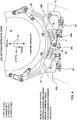
- the method includes providing an intermediate cradle 65, preferably with a first right cradle half 6 and a second left cradle half 5.
- the method includes providing a lateral link 4, the lateral link 4 having a first end 68a for grounding to the aircraft body 54 and a second distal end 68c, the second distal end 68c distal from the first end 68a.
- the method includes mounting the first engine 50to the aircraft body 54, with the top fluid chamber fluid elastomer engine mount bottom end 62 grounded to the aircraft body 54, the bottom fluid chamber fluid elastomer engine mount bottom end 62 grounded to the aircraft body 54, with the intermediate cradle 65 disposed between the top fluid chamber fluid elastomer engine mount 60t and the bottom fluid chamber fluid elastomer engine mount 60b and the first engine 50, with a fluid conduit 70 connecting the top fluid chamber fluid engine mount top fluid chamber 64t with the bottom fluid chamber fluid engine mount bottom fluid chamber 64b wherein the rotary wing aircraft body persistent in flight operational rotating frequency vibration is inhibited from reaching the first engine 50.
- the method includes attaching the lateral link first end 68a to the aircraft body 54 and attaching the second distal end 68c to the intermediate cradle 65.
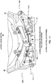
- the second distal end 68c is attached to the intermediate cradle 65 between the top fluid chamber fluid engine mount 60t and the bottom fluid chamber fluid engine mount 60b, preferably proximate a midpoint between the mounts 60, preferably proximate a cradle joint 9 (preferbly with cradle joint 9 connecting the cradle halfs 6,5), preferably with a lateral link joint 10.
- the method includes disposing at least a first scissor link 72 between the intermediate cradle 65 and the first engine 50.
- a first scissor link 72 is provided for linking the intermediate cradle first upper arm 74 to the engine 50 and a second scissor link 72' is provided for linking the intermediate cradle second upper arm 74' to the engine 50.
- the scissor links are comprised of an upper scissor link 2 and a lower scissor link 3.
- the at least first scissor link 72 is attached to the intermediate cradle arm 74 and an engine frame 76 of the first engine 50, preferably with a cradle to scissor link joint 8, preferably with the cradle to scissor link joints 8 are comprised of a spherical joint between the cradle upper arm end and the scissor link with upper scissor link 2 and lower scissor link 3.
- the scissors links are connected with the engine 50 and its engine frame 76 with scissor link to engine joints 11, and preferably a scissor link eye bolt 12.
- the system 1 includes failsafes 13, preferably waiting failsafes 13 between the cradle 65 and the engine frame 76.
- the failsafe 13 are comprise of a failsafe pin received inside a failsafe hole, with a failsafe clearance between the pin and hole provising for the failsafe to be nonconnected and waiting to connect and engage each other upon a failure.
- the intermediate cradle 65 is comprised of the cradle halfs 6,5 joined together with cradle joint 9, preferably with intermediate cradle center cradle joint 9 comprised ofa center cradle revolute joint.
- the intermediate cradle center cradle joint 9 is a revolute joint disposed between the top fluid chamber fluid engine mount 60t and the bottom fluid chamber fluid engine mount 60b.
- static determinacy is provided for the engine mounting system 1.
- the lateral link second distal end 68c is attached to the intermediate cradle 65 proximate the center cradle joint 9, preferably between the top fluid chamber fluid engine mount 60t and the bottom fluid chamber fluid engine mount 60b, and between the engine frame 76 and the aircraft body 54.
- the lateral link second distal end 68c is attached to the intermediate cradle 65 proximate the center cradle joint 9 through an elastomer 78.
- the method includes attaching the intermediate cradle 65 to the top fluid chamber fluid engine mount 60t with a revolute joint 7 providing a mount to cradle joint and attaching the intermediate cradle 65 to the bottom fluid chamber fluid engine mount 60b with a revolute joint 7 providing a mount to cradle joint.
- the engine 50 has a longitudinally extending center line 80, the longitudinally extending center line extending longitudinally fore and aft in the aircraft 52, with an intermediate cradle center cradle joint 9 oriented relative to the longitudinally extending center line 80, with the intermediate cradle center cradle joint 9 disposed between the top fluid chamber fluid engine mount 60t and the bottom fluid chamber fluid engine mount 60b, preferably with static determinacy provided for the engine mounting system 1.
- the method includes providing a plurality of spherical joints 100 to provide an engine mount system fore/aft degree of freedom, preferably with a lower hinge line 101 and an upper hinge line 101.
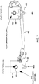
- the method includes providing a pressure sensor 102 for sensing the pressure of the fluid 90.
- the intermediate cradle 65 is disposed between the top fluid chamber fluid elastomer engine mount 60t and the bottom fluid chamber fluid elastomer engine mount 60b and the first engine 50, with the fluid conduit 70 connecting the top fluid chamber fluid engine mount top fluid chamber 64t with the bottom fluid chamber fluid engine mount bottom fluid chamber 64b the fluid 90 in the mounts and conduit oscillates back and forth and is tuned in relationship to the frequency of the rotary wing aircraft body persistent in flight operational rotating frequency vibration to provide a engine mount notch frequency 98 centered about the in flight operational rotating frequency vibration NP with transmission of such in flight operational rotating frequency vibration NP through the engine mounting system 1 from the aircraft body 54 into the engine 50 inhibited.
- the notch 98 frequency is centered about 21 Hz with the operational rotating frequency (P) of the helicopter about 3Hz producing persistent in flight operational rotating frequency vibration from the rotating blades in the aircraft body 54 centered about 21 Hz.
- the notch 98 frequency is tuned and centered about 19.5 Hz with the notch substantially including 21 Hz.
- the Dynamic Stiffness vs Frequency (K*) plot of Frequency (Hz) on the x axis and K* (lb/in) on the y axis is a plot of measured test data for a system 1 tuned at about 19.5 Hz.
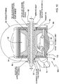
- the pumping and oscilating of the inertia fluid 90 back and forth between the chambers 64t,64b through the inertia fluid conduit 70 preferably generates fluid inertia forces for changing the mount operating characteristics at the persistent in flight operational rotating frequency vibration from the rotating blades in the aircraft wherein the rotary wing aircraft body persistent in flight operational rotating frequency vibration is inhibited from reaching the first engine 50 with the variable volume chambers 64t,64b and the variable position of the cradle attachment bushing 82 relative to the mount bottom end 62 inhibiting the transmission of the rotary wing aircraft body persistent in flight operational rotating frequency vibration from the body 54 up into the engine 50.
- the inner member 86 has an upper and a lower concavity 92.
- the upper concavity 92 provides fluid chamber 64t and contains fluid 90 and the lower concavity 92 does not provide a fluid chamber and does not contain a fluid 90.
- the lower concavity 92 provides fluid chamber 64b and contains fluid 90 and the upper concavity 92 does not provide a fluid chamber and does not contain a fluid 90.
- the conduit 70 provides an inertia track for the fluid 90 that confines and directs the fluid between the variable volume of the chambers 64t,64b.
- the oscillation of the fluid 90 within the inertia track conduit 70 provides an inertence mass like resistance to the mount inner member outer member pumping forces which is in phase with the input disturbance displacement and opposite in direction to the input acceleration.
- the inertial forces of the oscillating fluid reduces the dynamic stiffness of the mounts 60 at the predetermined frequency of the persistent in flight operational rotating frequency vibration from the rotating blades in the aircraft.
- different lengths (at least a first length and at least a second length) of the conduit 70 are provided to tune the inertial forces of the oscillating fluid in the conduit to tune the oscillating fluid reduced dynamic stiffness of the mounts 64 to correlate with the frequency of the persistent in flight operational rotating frequency vibration from the rotating blades in the aircraft.
- mount bottom ends 62 are connected and grounded to the aircraft body 54 with mount to airframe body grounding joints 14-1,14-2.
- top fluid mount 60t is protected from heat by a heat shield 15.
- bottom fluid mount 60b is protected from heat by a heat shield 16.
- the invention includes a helicopter engine mounting system 1 for mounting an engine 50 to an aircraft body 54 supported in flight by a rotary wing system 56 rotating with an operational rotating frequency (P) with a plurality of (N) rotating blades 58, the aircraft body 54 having a persistent in flight operational rotating frequency vibration from the rotating blades 58.
- a helicopter engine mounting system 1 for mounting an engine 50 to an aircraft body 54 supported in flight by a rotary wing system 56 rotating with an operational rotating frequency (P) with a plurality of (N) rotating blades 58, the aircraft body 54 having a persistent in flight operational rotating frequency vibration from the rotating blades 58.
- the engine mounting system includes a top fluid chamber fluid elastomer engine mount 60t and a bottom fluid chamber fluid elastomer engine mount 60b, the top fluid chamber fluid elastomer engine mount 60t having a bottom end 62 for grounding to the aircraft body 54, and the bottom fluid chamber fluid elastomer engine mount 60b having a bottom end 62 for grounding to the aircraft body 54, the top fluid chamber fluid elastomer engine mount having a top fluid chamber 64t distal from the top fluid chamber fluid elastomer engine mount bottom end 62, the bottom fluid chamber fluid elastomer engine mount having a bottom fluid chamber 64b proximate the bottom fluid chamber fluid elastomer engine mount bottom end 62.
- the engine mounting system 1 includes an intermediate cradle 65 with a lateral link 4, the lateral link 4 having a first end 68a for grounding to the aircraft body 54 and a second distal end 68c , the second distal end 68c distal from the first end 68a, the second distal end 68c linked to the intermediate cradle 65.
- top fluid chamber fluid elastomer engine mount bottom end 62 grounded to the aircraft body 54
- the bottom fluid chamber fluid elastomer engine mount bottom end 62 grounded to the aircraft body 54
- the intermediate cradle 65 disposed between the top fluid chamber fluid elastomer engine mount 60t and the bottom fluid chamber fluid elastomer engine mount 60b and the engine 50
- a fluid conduit 70 connecting the top fluid chamber fluid engine mount top fluid chamber 64t with the bottom fluid chamber fluid engine mount bottom fluid chamber 64b wherein a transfer of the persistent in flight operational rotating frequency vibration from the aircraft body 54 to the engine 50 is inhibited.
- the pumping and oscilating of the inertia fluid 90 back and forth between the chambers 64t,64b through the inertia fluid conduit 70 preferably generates fluid inertia forces for changing the mount operating characteristics at the persistent in flight operational rotating frequency vibration from the rotating blades in the aircraft wherein the rotary wing aircraft body persistent in flight operational rotating frequency vibration is inhibited from reaching the first engine 50 with the variable volume chambers 64t,64b and the variable position of the cradle attachment bushing 82 relative to the mount bottom end 62 inhibiting the transmission of the rotary wing aircraft body persistent in flight operational rotating frequency vibration from the body 54 up into the engine 50.
- the inner member 86 has an upper and a lower concavity 92.
- the upper concavity 92 provides fluid chamber 64t and the lower concavity 92 does not provide a fluid chamber.
- the lower concavity 92 provides fluid chamber 64b and the upper concavity 92 does not provide a fluid chamber.
- the conduit 70 provides an inertia track for the fluid 90 that confines and directs the fluid between the variable volume of the chambers 64t,64b. The oscillation of the fluid 90 within the inertia track conduit 70 provides an inertence mass like resistance to the mount inner member outer member pumping forces which is in phase with the input disturbance displacement and opposite in direction to the input acceleration.
- the inertial forces of the oscillating fluid reduces the dynamic stiffness of the mounts 64 at the predetermined frequency of the the persistent in flight operational rotating frequency vibration from the rotating blades in the aircraft.
- different lengths (at least a first length and at least a second length) of the conduit 70 are provided to tune the inertial forces of the oscillating fluid in the conduit to tune the oscillating fluid reduced dynamic stiffness of the mounts 64 to correlate with the frequency of the the persistent in flight operational rotating frequency vibration from the rotating blades in the aircraft.
- the lateral link second distal end 68c is attached to the intermediate cradle 65 between the top fluid chamber fluid engine mount 60t and the bottom fluid chamber fluid engine mount 60b.
- the system 1 includes at least a first scissor link 72 between the intermediate cradle 65 and the engine 50.
- the at least first scissor link 72 is attached to the intermediate cradle 65 and an encircling engine frame 76 of the engine 50, preferably with a spherical joint 100 between cradle upper arm end and scissor link with upper scissor link 2 and lower scissor link 3.
- the engine 50 has a longitudinally extending center line 80, the longitudinally extending center line 80 extending longitudinally fore and aft in the aircraft 52, and the intermediate cradle 65 includes a center cradle revolute joint 9 oriented relative to the longitudinally extending center line 80.
- the intermediate cradle center cradle joint 9 is a revolute joint disposed below the longitudinally extending center line 80 and between the top fluid chamber fluid engine mount 60t and the bottom fluid chamber fluid engine mount 60b, preferably with static determinacy provided for the engine mounting system 1.
- the lateral link second distal end 68c is attached to the intermediate cradle 65 proximate the center cradle joint 9.
- the lateral link second distal end 68c is attached between the top fluid chamber fluid engine mount 60t and the bottom fluid chamber fluid engine mount 60b, and between the engine frame 76 and the aircraft body 54.
- the lateral link second distal end 68c is attached to the intermediate cradle 65 proximate the center cradle joint 9 through an elastomer 78.
- the intermediate cradle 65 is attached to the top fluid chamber fluid engine mount 60t with a revolute joint 7 and is attached to the bottom fluid chamber fluid engine mount 60b with a revolute joint 7.
- the engine 50 has a longitudinally extending center line 80, the longitudinally extending center line 80 extending longitudinally fore and aft in the aircraft 52, with an intermediate cradle center cradle joint 9 oriented relative to the longitudinally extending center line 80, with the intermediate cradle center cradle joint 9 disposed between the top fluid chamber fluid engine mount 60t and the bottom fluid chamber fluid engine mount 60b.
- static determinacy is provided for the engine mounting system 1.
- the system includes a plurality of spherical joints 100 to provide an engine mount system fore/aft degree of freedom, preferably with a lower hinge line 101 and an upper hinge line 101.
- the system includes a pressure sensor 102 for sensing the pressure of the fluid 90.
- the intermediate cradle 65 is disposed between the top fluid chamber fluid elastomer engine mount 60t and the bottom fluid chamber fluid elastomer engine mount 60b and the first engine 50, with the fluid conduit 70 connecting the top fluid chamber fluid engine mount top fluid chamber 64t with the bottom fluid chamber fluid engine mount bottom fluid chamber 64b with the fluid 90 in the mounts 60 and conduit 70 oscillating back and forth in a tuned relationship with the frequency of the rotary wing aircraft body persistent in flight operational rotating frequency vibration to provide an engine mount notch frequency 98 centered about the in flight operational rotating frequency vibration NP with transmission of such in flight operational rotating frequency vibration NP through the engine mounting system 1 in a direction from the aircraft body 54 into the engine 50 inhibited.
- the notch 98 frequency is centered about 21 Hz with the operational rotating frequency (P) of the helicopter 52 about 3Hz producing persistent in flight operational rotating frequency vibration from the rotating blades 58 in the aircraft body 54 centered about 21 Hz.
- the notch 98 frequency is tuned and centered about 19.5 Hz with the notch substantially including 21 Hz.
- the Dynamic Stiffness vs Frequency (K*) plot of Frequency (Hz) on the x axis and K* (lb/in) on the y axis is a plot of measured test data for a system 1 tuned at about 19.5 Hz.
- the invention includes a method of making an engine mounting system 1 for an engine 50 in an aircraft body 54 having a persistent in flight operational rotating frequency vibration.
- the method includes providing a top fluid chamber fluid elastomer engine mount 60t and a bottom fluid chamber fluid elastomer engine mount 60b, the top fluid chamber fluid elastomer engine mount 60t having a bottom end 62 for grounding to the aircraft body 54, and the bottom fluid chamber fluid elastomer engine mount 60b having a bottom end 62 for grounding to the aircraft body 54, the top fluid chamber fluid elastomer engine mount 60t having a top fluid chamber 64t distal from the top fluid chamber fluid elastomer engine mount bottom end 62, the bottom fluid chamber fluid elastomer engine mount 60b having a bottom fluid chamber 64b proximate the bottom fluid chamber fluid elastomer engine mount bottom end 62.
- the method includes providing an intermediate cradle 65 with a center cradle revolute joint 9.
- the method includes providing a lateral link 4, the lateral link 4 having a first end 68a for grounding to the aircraft body 54 and a second distal end 68c, the second distal end 68c distal from the first end 68a for linking to the intermediate cradle 65.
- the method includes the intermediate cradle 65 attachable between the engine 50 and the top fluid chamber fluid engine mount bottom end 62 and the bottom fluid chamber fluid engine mount bottom end 62 with the intermediate cradle center cradle revolute joint 9 between the top fluid chamber fluid engine mount 60t and the bottom fluid chamber fluid engine mount 60t with a fluid conduit 70 connecting the top fluid chamber fluid engine mount top fluid chamber 64t with the bottom fluid chamber fluid engine mount bottom fluid chamber 64b wherein the aircraft body persistent in flight operational rotating frequency vibration is inhibited from reaching the engine 50 by a mass of fluid 90 resonating between the top fluid chamber fluid engine mount top fluid chamber 64t and the bottom fluid chamber fluid engine mount bottom fluid chamber 64b.
- the transmission of the NP 21Hz persistent in flight operational rotating frequency vibration through the engine mounts 60 is inhibited by the tuned notch 98 filter of the fluid mass 90 oscillating between the mounts 60 which combines in an out of phase manner with the elastomer response of the mounts, with the tuned notch 98 filter center about the NP 21Hz troublesome vibration.
- the intermediate cradle center cradle joint 9 is a revolute joint disposed between the top fluid chamber fluid engine mount 60t and the bottom fluid chamber fluid engine mount 60b wherein static determinacy is provided for the engine mounting system 1.
- the method includes attaching the second distal end 68c of the link 4 to the intermediate cradle 65 through an elastomer member 78 between the top fluid chamber fluid engine mount 60t and the bottom fluid chamber fluid engine mount 60b.
- the method includes providing a first scissor link 72 and a second scissor link 72' between the intermediate cradle 65 and the engine 50.
- the scissor links 72, 72' are attached to the intermediate cradle 65 and an engine frame 76 of the first engine 50 with a spherical joint 100 between the cradle 65 and scissor link.
- the lateral link second distal end 68c is attached to the intermediate cradle 65 proximate the center cradle joint 9, preferably between the top fluid chamber fluid engine mount 60t and the bottom fluid chamber fluid engine mount 60b, and between the engine frame 76 and the aircraft body 54.
- the intermediate cradle 65 is attached to the top fluid chamber fluid engine mount 60t with a revolute joint 7 and the intermediate cradle 65 is attached to the bottom fluid chamber fluid engine mount 60b with a revolute joint 7.
- the engine 50 has a longitudinally extending center line 80, the longitudinally extending center line 80 extending longitudinally fore and aft in the aircraft 52, with the intermediate cradle center cradle joint 9 oriented relative to the longitudinally extending center line 80, with the intermediate cradle center cradle joint 9 disposed between the top fluid chamber fluid engine mount 60t and the bottom fluid chamber fluid engine mount 60b, preferably with static determinacy provided for the engine mounting system 1.
- the method includes providing a plurality of spherical joints 100 to provide an engine mount system fore/aft degree of freedom, preferably with a lower hinge line 101 and an upper hinge line 101.
- the method includes providing a pressure sensor 102 for sensing the pressure of the fluid 90.
- the fluid 90 in the fluid elastomer mounts 60 and conduit 70 oscillates back and forth and is tuned in relationship to the frequency of the rotary wing aircraft body persistent in flight operational rotating frequency vibration to provide an engine mount notch 98 frequency centered about the in flight operational rotating frequency vibration NP with transmission of such in flight operational rotating frequency vibration NP through the engine mounting system from the aircraft body 54 into the engine 50 inhibited.
- the notch 98 frequency is centered about 21 Hz with the operational rotating frequency (P) of the helicopter about 3Hz producing persistent in flight operational rotating frequency vibration from the rotating blades in the aircraft body 54 centered about 21 Hz.
- the notch 98 frequency is tuned and centered about 19.5 Hz with the notch substantially including 21 Hz.
- the Dynamic Stiffness vs Frequency (K*) plot of Frequency (Hz) on the x axis and K* (lb/in) on the y axis is a plot of measured test data for a system 1 tuned at about 19.5 Hz.
- the invention includes a method of making a mounting system for mounting a subject.
- the method includes providing a top fluid chamber fluid mount and a bottom fluid chamber fluid mount, said top fluid chamber fluid mount having a bottom end for grounding to a body, and said bottom fluid chamber fluid mount having a bottom end for grounding to said body, said top fluid chamber fluid mount having a top fluid chamber distal from said top fluid chamber fluid mount bottom end, said bottom fluid chamber fluid mount having a bottom fluid chamber proximate said bottom fluid chamber fluid mount bottom end.
- the method includes providing an intermediate cradle with a center cradle revolute joint.
- the method includes providing a lateral link, said lateral link having a first end for grounding to said body and a second distal end, said second distal end distal from said first end for linking to said intermediate cradle, said intermediate cradle attachable between said subject and said top fluid chamber fluid mount and said bottom fluid chamber fluid mount with said intermediate cradle center cradle revolute joint between said top fluid chamber fluid mount and said bottom fluid chamber fluid mount with a fluid conduit connecting said top fluid chamber fluid mount top fluid chamber with said bottom fluid chamber fluid mount bottom fluid chamber wherein frequency notch vibrations are inhibited from transmission through said mounting system mounting said subject to said body by a mass of fluid moving between said top fluid chamber fluid mount top fluid chamber and said bottom fluid chamber fluid mount bottom fluid chamber.
- the mounting system preferably provides static determancy wherein preferably all loads can be calculated by hand calculations of force, moment, and balance.
- the invention includes an engine mount assembly 1 for mounting a subject engine 50 which produces a torque to an aircraft body 54 having a persistent troublesome frequency vibration.
- the engine mount assembly 1 including a first side fluid chamber fluid elastomer engine mount 60 and a second side fluid chamber fluid elastomer engine mount 60, the first side fluid chamber fluid elastomer engine mount groundable to the body 54 having the persistent troublesome frequency vibration, and the second side fluid chamber fluid elastomer engine mount groundable to the body 54 having the persistent troublesome frequency vibration, the first side fluid chamber fluid elastomer engine mount having a first fluid chamber 64, the second side fluid chamber fluid elastomer engine mount having a second fluid chamber 64.
- the engine mount assembly including an intermediate cradle 65 with a lateral link 4, the lateral link having a first end 68a for grounding to the body 54 having the persistent troublesome frequency vibration and a second distal end 68c, the second distal end distal from the first end, the second distal end linked to the intermediate cradle 65.
- the first side fluid chamber fluid elastomer engine mount 60 is grounded to the body 54 having the persistent troublesome frequency vibration
- the second side fluid chamber fluid elastomer engine mount 60 grounded to the body 54 having the persistent troublesome frequency vibration
- the intermediate cradle 65 disposed between the first fluid chamber fluid engine mount and the second side fluid chamber fluid engine mount and the engine
- a fluid conduit 70 connecting the first side fluid chamber fluid engine mount fluid chamber 64 with the second side fluid chamber fluid engine mount fluid chamber 64 wherein the torque generates a positive fluid pressure within the fluid chambers 64 and the fluid conduit
- the intermediate cradle 65 has an intermediate cradle center cradle joint between the first side fluid chamber fluid elastomer engine mount and the second side fluid chamber fluid elastomer engine mount with the first side fluid chamber fluid elastomer engine mount and the second side fluid chamber fluid elastomer engine mount sharing a plurality of loads while a transfer of the persistent troublesome frequency vibration from the body 54 to the engine 50 is inhibited.
- the first side fluid chamber fluid elastomer engine mount 60 has a first fluid elastomer mount primary line of action 96 and the second side fluid chamber fluid elastomer engine mount 60 has a second fluid elastomer mount primary line of action 96 with the first fluid elastomer mount primary line of action substantially parallel with the second fluid elastomer mount primary line of action.
- the engine torque generating positive fluid pressure within the fluid chambers 64 and the fluid conduit 70 inhibits a fluid cavitation in the first side fluid chamber fluid elastomer engine mount and the second side fluid chamber fluid elastomer engine mount during a plurality of translation vibration isolation movements of the assembly.
- a stiffness of the assembly 1 in a second translation direction nonparallel with the force of gravity is controlled by the lateral link 4 with the assembly having a static determinacy.
- the intermediate cradle 65 has a first side upper arm 74 providing a first side engine load application point, the first side upper arm first side engine load application point distal from the intermediate cradle center cradle joint 9 and a second side upper arm 74' providing a second side engine load application point, the second side upper arm second side engine load application point distal from the intermediate cradle center cradle joint 9.
- first side scissor link 72 is between the first side upper arm first side engine load application point and the engine 50 and a second side scissor link 72' between the second side upper arm second side engine load application point and the engine 50.
- the intermediate cradle center cradle joint 9 is proximate the body 54.
- the assembly 1 and the fluid conduit 70 and the first side fluid chamber fluid elastomer engine mount 60 and the second side fluid chamber fluid elastomer engine mount 60 are free of a fluid volume compensator chamber.
- the assembly includes a pressure sensor 102 for sensing the pressure of the fluid 90.
- the fluid elastomer engine isolation mounts 60 provide a high stiffness to torque produced by the engine 50 through the generation of hydrostatic pressure within the fluid chambers 64 and the connected conduit 70.
- the fluid elastomer engine isolation mounts 60 are soft to provide isolation in a primary translational direction, with the primary translational direction oriented parallel with gravity, with further reduction at the tuned notch 98 frequency.
- the primary translational direction is oriented parallel with gravity with this preferably being the direction of the highest static loads.
- the natural 1G of load that is always present as a mean.
- the normal engine torque produces an addition of pressure within the mounts 60 as opposed to a negative pressure.
- the two fluid elastomer engine isolation mounts 60 are oriented with their primary line of action 96 parallel with each other, and parallel with the primary maneuver load direction.
- the positive hydrostatic pressure that is produced by the engine torque reaction generates fluid pressure to inhibit cavitation in the two fluid elastomer engine isolation mounts 60 due to fluctuations of dynamic pressures due to translational vibration isolation movements.
- the two fluid elastomer engine isolation mounts isolators 60, cradle 65, and associated joints provide a system/assembly/method wherein the stiffness in the second translational direction (preferably perpendicular to gravity) is controlled by the lateral link 4, preferably only by the lateral link 4 itself.
- this 4-bar system/assembly/method provides static determinacy for the engine isolation mounting system 1.
- the center joint 9 in the intermediate cradle 65 provides freedom for engine 50 thermal growth, and tolerance stack, and preferably at the same time forces the first side and second side cradle halves 6,5 to share loads produced by aircraft maneuvers in the lateral and vertical directions and inhibits all lateral loads being supported on only one side of the engine 50.
- the center cradle joint 9 is located distal and most preferably at an extreme distance as far from the engine load application point as possible.
- the center cradle joint 9 and the distal first side upper arm first side engine load application point 174 and the second side upper arm second side engine load application point 174' inhibits the amount of radial load produced on the engine attachment points due to aircraft maneuvers and torque.
- the system/assembly/methods protect the engine 50 from the aircraft body persistent troublesome frequency vibration induced excitation at 21Hz. That persistent troublesome frequency excitation which the system/assembly/methods inhibit the transmission of is produced by the 7P vibration of the main rotor of the helicopter and is transmitted throughout the airframe body 54.
- the engine system/assembly/methods provide controlled stiffness that can be effectively sized and tuned to provide frequency placement and isolation.
- the rigid body modes of the engine 50 relative to the aircraft body 54 are maintained within the 8-15 Hz bandwidth, and with the torsional/roll modes close to 15Hz, or above 27Hz. Dynamically this preferably provides effective isolation of the 21Hz. excitation.
- the engine system/assembly/methods utilize the mass of fluid 90 that is adjustable. With the mass of fluid 90 adjustable in the system/assembly, such as with adjustments to the fluid volume in the conduit 70 or fluid density of fluid 90, the system/assembly is tunable to effectively create a notch 98 in the dynamic stiffness at a specified frequency.
- This preferably provides a statically stiff system 1 which contains a dynamic notch 98 in response; and in a preferred seven blade helicopter embodiment tuned at about 21 Hz.
- the notch 98 frequency is tuned and centered about 19.5 Hz with the notch substantially including 21 Hz.
- the Dynamic Stiffness vs Frequency (K*) plot of Frequency (Hz) on the x axis and K* (lb/in) on the y axis is a plot of measured test data for a system 1 tuned at about 19.5 Hz.
- the engine system/assembly/methods provide a statically stiff and dynamically soft isolator system 1.
- the isolator 1 uses a tuned fluid mass 90 to create a notch 98 filter at a specified preferred frequency.
- the engine system/assembly mounts 60 have fluid chambers and passages for a small amount of fluid and takes advantage of the hydraulic pumping action of the bonded elastomer sections 84 and inner member 86 to transfer the fluidbetween the mounts.
- the response of the fluid 90 is tuned so that it combines in an out-of-phase manner with the elastomer response of bonded elastomer sections 84, resulting in increased vibration isolation at a given frequency.
- the engine system/assembly isolator mounts 60 provide for placement of the notch 98 frequency, Fnotch, at a desired frequency which coincides with a maximum tonal excitation band.
- the mounts 60, conduit 70 and fluid inertia 90 are tuned to provide the notch 98 at the 7P excitation frequency of 21 Hz.
- the notch 98 frequency is tuned and centered about 19.5 Hz with the notch substantially including 21 Hz.
- the Dynamic Stiffness vs Frequency (K*) plot of Frequency (Hz) on the x axis and K* (lb/in) on the y axis is a plot of measured test data for a system 1 tuned at about 19.5 Hz.
- the system/assembly/methods utilize a high-pressure, braided, fluid hose as a fluid conduit 70 connected between the two fluid chambers 64.
- the mounts 60 are preferably installed inverted with respect to each other.
- one mount contains a fluid volume on top, while the other is on the bottom.
- the fluid 90 is compressed within both mounts 60 and the hose conduit 70. This state of hydrostatic compression provides a very high effective stiffness to react the torsional load.
- the ability to tune is preferably provided by adjustments chosen from the tuning adjustment character group comprise of elastomer section thickness, elastomer modulus, fluid density, piston area, hose area, hose length (conduit interia track length), volume stiffness and combinations of such tuning adjustment characters.
Landscapes
- Engineering & Computer Science (AREA)
- Aviation & Aerospace Engineering (AREA)
- General Engineering & Computer Science (AREA)
- Manufacturing & Machinery (AREA)
- Mechanical Engineering (AREA)
- Transportation (AREA)
- Vibration Prevention Devices (AREA)
Abstract
Description
- This application claims the benefit of
US Provisional Application No. 61/397,607 filed on June 14, 2010 - The invention relates to the field of rotary wing aircraft. The invention relates to the field of rotary wing aircraft engine mounting systems. More particularly the invention relates to the field of mounting aircraft engines in rotary wing aircrafts that have persistent in flight operational rotating frequency vibrations.
- In an embodiment the invention includes a method of mounting an engine in a rotary wing aircraft. The method includes providing a rotary wing aircraft having an aircraft body supported in flight through an exterior air space by a rotary wing system rotating with an operational rotating frequency (P) with a plurality of (N) rotary wings, the rotary wing aircraft body having a persistent in flight operational rotating frequency vibration. The method includes providing a first engine, the first engine for providing power to rotate the rotary wing system at the rotary wing system operational rotating frequency (P). The method includes providing a top fluid chamber fluid elastomer engine mount and a bottom fluid chamber fluid elastomer engine mount, the top fluid chamber fluid elastomer engine mount having a bottom end for grounding to the aircraft body, and the bottom fluid chamber fluid elastomer engine mount having a bottom end for grounding to the aircraft body. The top fluid chamber fluid engine mount having a top fluid chamber distal from the top fluid chamber fluid engine mount bottom end, the bottom fluid chamber fluid engine mount having a bottom fluid chamber proximate the bottom fluid chamber fluid engine mount bottom end. The method includes providing an intermediate cradle. The method includes providing a lateral link, the lateral link having a first end for grounding to the aircraft body and a second distal end, the second distal end distal from the first end. The method includes mounting the first engine to the aircraft body, with the top fluid chamber fluid elastomer engine mount bottom end grounded to the aircraft body, the bottom fluid chamber fluid elastomer engine mount bottom end grounded to the aircraft body, with the intermediate cradle disposed between the top fluid chamber fluid elastomer engine mount and the bottom fluid chamber fluid elastomer engine mount and the first engine, with a fluid conduit connecting the top fluid chamber fluid engine mount top fluid chamber with the bottom fluid chamber fluid engine mount bottom fluid chamber wherein the rotary wing aircraft body persistent in flight operational rotating frequency vibration is inhibited from reaching the first engine. The mounting system preferably provides static determancy wherein preferably all loads can be calculated by hand calculations of force, moment, and balance.
- In an embodiment the invention includes a helicopter engine mounting system for mounting an engine to an aircraft body supported in flight by a rotary wing system rotating with an operational rotating frequency (P) with a plurality of (N) rotating blades, the aircraft body having a persistent in flight operational rotating frequency vibration from the rotating blades. The engine mounting system includes a top fluid chamber fluid elastomer engine mount and a bottom fluid chamber fluid elastomer engine mount, the top fluid chamber fluid elastomer engine mount having a bottom end for grounding to the aircraft body, and the bottom fluid chamber fluid elastomer engine mount having a bottom end for grounding to the aircraft body, the top fluid chamber fluid elastomer engine mount having a top fluid chamber distal from the top fluid chamber fluid elastomer engine mount bottom end, the bottom fluid chamber fluid elastomer engine mount having a bottom fluid chamber proximate the bottom fluid chamber fluid elastomer engine mount bottom end. The engine mounting system includes an intermediate cradle with a lateral link, the lateral link having a first end for grounding to the aircraft body and a second distal end, the second distal end distal from the first end, the second distal end linked to the intermediate cradle. The top fluid chamber fluid elastomer engine mount bottom end grounded to the aircraft body, the bottom fluid chamber fluid elastomer engine mount bottom end grounded to the aircraft body, with the intermediate cradle disposed between the top fluid chamber fluid elastomer engine mount and the bottom fluid chamber fluid elastomer engine mount and the engine, with a fluid conduit connecting the top fluid chamber fluid engine mount top fluid chamber with the bottom fluid chamber fluid engine mount bottom fluid chamber wherein a transfer of the persistent in flight operational rotating frequency vibration from the aircraft body to the engine is inhibited. The mounting system preferably provides static determancy wherein preferably all loads can be calculated by hand calculations of force, moment, and balance.
- In an embodiment the invention includes a method of making an engine mounting system for an engine in an aircraft body having a persistent in flight operational rotating frequency vibration. The method includes providing a top fluid chamber fluid elastomer engine mount and a bottom fluid chamber fluid elastomer engine mount, the top fluid chamber fluid elastomer engine mount having a bottom end for grounding to the aircraft body, and the bottom fluid chamber fluid elastomer engine mount having a bottom end for grounding to the aircraft body, the top fluid chamber fluid elastomer engine mount having a top fluid chamber distal from the top fluid chamber fluid elastomer engine mount bottom end, the bottom fluid chamber fluid elastomer engine mount having a bottom fluid chamber proximate the bottom fluid chamber fluid elastomer engine mount bottom end. The method includes providing an intermediate cradle with a center cradle revolute joint. The method includes providing a lateral link, the lateral link having a first end for grounding to the aircraft body and a second distal end, the second distal end distal from the first end for linking to the intermediate cradle. The method includes the intermediate cradle attachable between the engine and the top fluid chamber fluid engine mount bottom end and the bottom fluid chamber fluid engine mount bottom end with the intermediate cradle center cradle revolute joint between the top fluid chamber fluid engine mount and the bottom fluid chamber fluid engine mount with a fluid conduit connecting the top fluid chamber fluid engine mount top fluid chamber with the bottom fluid chamber fluid engine mount bottom fluid chamber wherein the aircraft body persistent in flight operational rotating frequency vibration is inhibited from reaching the engine by a mass of fluid resonating between the top fluid chamber fluid engine mount top fluid chamber and the bottom fluid chamber fluid engine mount bottom fluid chamber. The mounting system preferably provides static determancy wherein preferably all loads can be calculated by hand calculations of force, moment, and balance.
- In an embodiment the invention includes an engine mount assembly for mounting an engine which produces a torque to an aircraft body having a persistent troublesome frequency vibration. The engine mount assembly including a first side fluid chamber fluid elastomer engine mount and a second side fluid chamber fluid elastomer engine mount, the first side fluid chamber fluid elastomer engine mount groundable to the body having the persistent troublesome frequency vibration, and the second side fluid chamber fluid elastomer engine mount groundable to the body having the persistent troublesome frequency vibration, the first side fluid chamber fluid elastomer engine mount having a first fluid chamber, the second side fluid chamber fluid elastomer engine mount having a second fluid chamber. The engine mount assembly including an intermediate cradle with a lateral link, the lateral link having a first end for grounding to the body having the persistent troublesome frequency vibration and a second distal end, the second distal end distal from the first end, the second distal end linked to the intermediate cradle. The first side fluid chamber fluid elastomer engine mount is grounded to the body having the persistent troublesome frequency vibration, the second side fluid chamber fluid elastomer engine mount grounded to the body having the persistent troublesome frequency vibration, with the intermediate cradle disposed between the first fluid chamber fluid engine mount and the second side fluid chamber fluid engine mount and the engine, with a fluid conduit connecting the first side fluid chamber fluid engine mount fluid chamber with the second side fluid chamber fluid engine mount fluid chamber wherein the torque generates a positive fluid pressure within the fluid chambers and the fluid conduit and the intermediate cradle has an intermediate cradle center cradle joint between the first side fluid chamber fluid elastomer engine mount and the second side fluid chamber fluid elastomer engine mount with the first side fluid chamber fluid elastomer engine mount and the second side fluid chamber fluid elastomer engine mount sharing a plurality of loads while a transfer of the persistent troublesome frequency vibration from the body to the engine is inhibited. The mounting system preferably provides static determancy wherein preferably all loads can be calculated by hand calculations of force, moment, and balance.
- In an embodiment the invention includes a method of making a mounting system for mounting a subject. The method includes providing a top fluid chamber fluid mount and a bottom fluid chamber fluid mount, said top fluid chamber fluid mount having a bottom end for grounding to a body, and said bottom fluid chamber fluid mount having a bottom end for grounding to said body, said top fluid chamber fluid mount having a top fluid chamber distal from said top fluid chamber fluid mount bottom end, said bottom fluid chamber fluid mount having a bottom fluid chamber proximate said bottom fluid chamber fluid mount bottom end. The method includes providing an intermediate cradle with a center cradle revolute joint. The method includes providing a lateral link, said lateral link having a first end for grounding to said body and a second distal end, said second distal end distal from said first end for linking to said intermediate cradle, said intermediate cradle attachable between said subject and said top fluid chamber fluid mount and said bottom fluid chamber fluid mount with said intermediate cradle center cradle revolute joint between said top fluid chamber fluid mount and said bottom fluid chamber fluid mount with a fluid conduit connecting said top fluid chamber fluid mount top fluid chamber with said bottom fluid chamber fluid mount bottom fluid chamber wherein frequency notch vibrations are inhibited from transmission through said mounting system mounting said subject to said body by a mass of fluid moving between said top fluid chamber fluid mount top fluid chamber and said bottom fluid chamber fluid mount bottom fluid chamber. The mounting system preferably provides static determancy wherein preferably all loads can be calculated by hand calculations of force, moment, and balance.
- It is to be understood that both the foregoing general description and the following detailed description are exemplary of the invention, and are intended to provide an overview or framework for understanding the nature and character of the invention as it is claimed. The accompanying drawings are included to provide a further understanding of the invention, and are incorporated in and constitute a part of this specification. The drawings illustrate various embodiments of the invention, and together with the description serve to explain the principals and operation of the invention.
- Additional features and advantages of the invention will be set forth in the detailed description which follows, and in part will be readily apparent to those skilled in the art from that description or recognized by practicing the invention as described herein, including the detailed description which follows, the claims, as well as the appended drawings.
- Reference will now be made in detail to the present preferred embodiments of the invention, examples of which are illustrated in the accompanying drawings.
- In an embodiment the invention includes a method of mounting a
subject engine 50 in arotary wing aircraft 52. The method includes providing arotary wing aircraft 52 having anaircraft body 54 supported in flight through an exterior air space by arotary wing system 56 rotating with an operational rotating frequency (P) with a plurality of (N)rotary wings 58, the rotarywing aircraft body 54 having a persistent in flight operational rotating frequency vibration. The method includes providing afirst subject engine 50, the first engine 50for providing power to rotate therotary wing system 56 at the rotary wing system operational rotating frequency (P). The method includes providing a top fluid chamber fluidelastomer engine mount 60t and a bottom fluid chamber fluidelastomer engine mount 60b, the top fluid chamber fluidelastomer engine mount 60t having abottom end 62 for grounding to theaircraft body 54, and the bottom fluid chamber fluidelastomer engine mount 60b having abottom end 62 for grounding to theaircraft body 54. The top fluid chamberfluid engine mount 60t having atop fluid chamber 64t distal from the top fluid chamber fluidmount bottom end 62, the bottom fluid chamberfluid engine mount 60b having abottom fluid chamber 64b proximate the bottom fluid chamber fluid enginemount bottom end 62. The method includes providing anintermediate cradle 65, preferably with a firstright cradle half 6 and a secondleft cradle half 5. The method includes providing alateral link 4, thelateral link 4 having afirst end 68a for grounding to theaircraft body 54 and a seconddistal end 68c, the seconddistal end 68c distal from thefirst end 68a. The method includes mounting the first engine 50to theaircraft body 54, with the top fluid chamber fluid elastomer enginemount bottom end 62 grounded to theaircraft body 54, the bottom fluid chamber fluid elastomer enginemount bottom end 62 grounded to theaircraft body 54, with theintermediate cradle 65 disposed between the top fluid chamber fluidelastomer engine mount 60t and the bottom fluid chamber fluidelastomer engine mount 60b and thefirst engine 50, with afluid conduit 70 connecting the top fluid chamber fluid engine mounttop fluid chamber 64t with the bottom fluid chamber fluid engine mountbottom fluid chamber 64b wherein the rotary wing aircraft body persistent in flight operational rotating frequency vibration is inhibited from reaching thefirst engine 50. - Preferably the method includes attaching the lateral link
first end 68a to theaircraft body 54 and attaching the seconddistal end 68c to theintermediate cradle 65. Preferably the seconddistal end 68c is attached to theintermediate cradle 65 between the top fluid chamberfluid engine mount 60t and the bottom fluid chamberfluid engine mount 60b, preferably proximate a midpoint between themounts 60, preferably proximate a cradle joint 9 (preferbly withcradle joint 9 connecting thecradle halfs 6,5), preferably with alateral link joint 10. - Preferably the method includes disposing at least a
first scissor link 72 between theintermediate cradle 65 and thefirst engine 50. Preferably afirst scissor link 72 is provided for linking the intermediate cradle firstupper arm 74 to theengine 50 and a second scissor link 72' is provided for linking the intermediate cradle second upper arm 74' to theengine 50. Preferably the scissor links are comprised of anupper scissor link 2 and alower scissor link 3. - Preferably the at least
first scissor link 72 is attached to theintermediate cradle arm 74 and anengine frame 76 of thefirst engine 50, preferably with a cradle toscissor link joint 8, preferably with the cradle toscissor link joints 8 are comprised of a spherical joint between the cradle upper arm end and the scissor link withupper scissor link 2 andlower scissor link 3. Preferably the scissors links are connected with theengine 50 and itsengine frame 76 with scissor link toengine joints 11, and preferably a scissorlink eye bolt 12. Preferably thesystem 1 includesfailsafes 13, preferably waitingfailsafes 13 between thecradle 65 and theengine frame 76. Preferably thefailsafe 13 are comprise of a failsafe pin received inside a failsafe hole, with a failsafe clearance between the pin and hole provising for the failsafe to be nonconnected and waiting to connect and engage each other upon a failure. - Preferably the
intermediate cradle 65 is comprised of thecradle halfs cradle joint 9, preferably with intermediate cradlecenter cradle joint 9 comprised ofa center cradle revolute joint. - Preferably the intermediate cradle
center cradle joint 9 is a revolute joint disposed between the top fluid chamberfluid engine mount 60t and the bottom fluid chamberfluid engine mount 60b. Preferably with the method static determinacy is provided for theengine mounting system 1. - Preferably the lateral link second
distal end 68c is attached to theintermediate cradle 65 proximate thecenter cradle joint 9, preferably between the top fluid chamberfluid engine mount 60t and the bottom fluid chamberfluid engine mount 60b, and between theengine frame 76 and theaircraft body 54. - Preferably the lateral link second
distal end 68c is attached to theintermediate cradle 65 proximate thecenter cradle joint 9 through anelastomer 78. - Preferably the method includes attaching the
intermediate cradle 65 to the top fluid chamber fluid engine mount 60t with arevolute joint 7 providing a mount to cradle joint and attaching theintermediate cradle 65 to the bottom fluid chamberfluid engine mount 60b with arevolute joint 7 providing a mount to cradle joint. - Preferably the
engine 50 has a longitudinally extendingcenter line 80, the longitudinally extending center line extending longitudinally fore and aft in theaircraft 52, with an intermediate cradle center cradle joint 9 oriented relative to the longitudinally extendingcenter line 80, with the intermediate cradle center cradle joint 9 disposed between the top fluid chamberfluid engine mount 60t and the bottom fluid chamberfluid engine mount 60b, preferably with static determinacy provided for theengine mounting system 1. - Preferably the method includes providing a plurality of
spherical joints 100 to provide an engine mount system fore/aft degree of freedom, preferably with alower hinge line 101 and anupper hinge line 101. - Preferably the method includes providing a
pressure sensor 102 for sensing the pressure of the fluid 90. - Preferably with the
intermediate cradle 65 is disposed between the top fluid chamber fluidelastomer engine mount 60t and the bottom fluid chamber fluidelastomer engine mount 60b and thefirst engine 50, with thefluid conduit 70 connecting the top fluid chamber fluid engine mount topfluid chamber 64t with the bottom fluid chamber fluid engine mountbottom fluid chamber 64b the fluid 90 in the mounts and conduit oscillates back and forth and is tuned in relationship to the frequency of the rotary wing aircraft body persistent in flight operational rotating frequency vibration to provide a enginemount notch frequency 98 centered about the in flight operational rotating frequency vibration NP with transmission of such in flight operational rotating frequency vibration NP through theengine mounting system 1 from theaircraft body 54 into theengine 50 inhibited. In a preferred embodiment with a helicopter with seven rotating blades thenotch 98 frequency is centered about 21 Hz with the operational rotating frequency (P) of the helicopter about 3Hz producing persistent in flight operational rotating frequency vibration from the rotating blades in theaircraft body 54 centered about 21 Hz. In a preferred embodiment thenotch 98 frequency is tuned and centered about 19.5 Hz with the notch substantially including 21 Hz. The Dynamic Stiffness vs Frequency (K*) plot of Frequency (Hz) on the x axis and K* (lb/in) on the y axis is a plot of measured test data for asystem 1 tuned at about 19.5 Hz. The variable volume of thechambers bottom end 62 provided with the bondedelastomer 84 bonded between the mount nonelastomericinner member 86 and the mount nonelastomericouter member 88 pump and oscilate theinertia fluid 90 back and forth between thechambers inertia fluid conduit 70. The pumping and oscilating of theinertia fluid 90 back and forth between thechambers inertia fluid conduit 70 preferably generates fluid inertia forces for changing the mount operating characteristics at the persistent in flight operational rotating frequency vibration from the rotating blades in the aircraft wherein the rotary wing aircraft body persistent in flight operational rotating frequency vibration is inhibited from reaching thefirst engine 50 with thevariable volume chambers bottom end 62 inhibiting the transmission of the rotary wing aircraft body persistent in flight operational rotating frequency vibration from thebody 54 up into theengine 50. Preferably theinner member 86 has an upper and alower concavity 92. Preferably in the top fluid chamber fluid elastomer engine mount 60t theupper concavity 92 providesfluid chamber 64t and containsfluid 90 and thelower concavity 92 does not provide a fluid chamber and does not contain afluid 90. Preferably in the bottom fluid chamber fluidelastomer engine mount 60b thelower concavity 92 providesfluid chamber 64b and containsfluid 90 and theupper concavity 92 does not provide a fluid chamber and does not contain afluid 90. Preferably theconduit 70 provides an inertia track for the fluid 90 that confines and directs the fluid between the variable volume of thechambers inertia track conduit 70 provides an inertence mass like resistance to the mount inner member outer member pumping forces which is in phase with the input disturbance displacement and opposite in direction to the input acceleration. The inertial forces of the oscillating fluid reduces the dynamic stiffness of themounts 60 at the predetermined frequency of the persistent in flight operational rotating frequency vibration from the rotating blades in the aircraft. In preferred embodiments different lengths (at least a first length and at least a second length) of theconduit 70 are provided to tune the inertial forces of the oscillating fluid in the conduit to tune the oscillating fluid reduced dynamic stiffness of the mounts 64 to correlate with the frequency of the persistent in flight operational rotating frequency vibration from the rotating blades in the aircraft. - Preferably the mount bottom ends 62 are connected and grounded to the
aircraft body 54 with mount to airframe body grounding joints 14-1,14-2. Preferablytop fluid mount 60t is protected from heat by aheat shield 15. Preferablybottom fluid mount 60b is protected from heat by aheat shield 16. - In an embodiment the invention includes a helicopter
engine mounting system 1 for mounting anengine 50 to anaircraft body 54 supported in flight by arotary wing system 56 rotating with an operational rotating frequency (P) with a plurality of (N)rotating blades 58, theaircraft body 54 having a persistent in flight operational rotating frequency vibration from therotating blades 58. The engine mounting system includes a top fluid chamber fluidelastomer engine mount 60t and a bottom fluid chamber fluidelastomer engine mount 60b, the top fluid chamber fluidelastomer engine mount 60t having abottom end 62 for grounding to theaircraft body 54, and the bottom fluid chamber fluidelastomer engine mount 60b having abottom end 62 for grounding to theaircraft body 54, the top fluid chamber fluid elastomer engine mount having atop fluid chamber 64t distal from the top fluid chamber fluid elastomer engine mountbottom end 62, the bottom fluid chamber fluid elastomer engine mount having abottom fluid chamber 64b proximate the bottom fluid chamber fluid elastomer engine mountbottom end 62. Theengine mounting system 1 includes anintermediate cradle 65 with alateral link 4, thelateral link 4 having afirst end 68a for grounding to theaircraft body 54 and a seconddistal end 68c , the seconddistal end 68c distal from thefirst end 68a, the seconddistal end 68c linked to theintermediate cradle 65. The top fluid chamber fluid elastomer engine mountbottom end 62 grounded to theaircraft body 54, the bottom fluid chamber fluid elastomer engine mountbottom end 62 grounded to theaircraft body 54, with theintermediate cradle 65 disposed between the top fluid chamber fluidelastomer engine mount 60t and the bottom fluid chamber fluidelastomer engine mount 60b and theengine 50, with afluid conduit 70 connecting the top fluid chamber fluid engine mount topfluid chamber 64t with the bottom fluid chamber fluid engine mountbottom fluid chamber 64b wherein a transfer of the persistent in flight operational rotating frequency vibration from theaircraft body 54 to theengine 50 is inhibited. The variable volume of thechambers bottom end 62 provided with the bondedelastomer 84 bonded between the mountinner member 86 and the mountouter member 88 pump and oscilate theinertia fluid 90 back and forth between thechambers inertia fluid conduit 70. The pumping and oscilating of theinertia fluid 90 back and forth between thechambers inertia fluid conduit 70 preferably generates fluid inertia forces for changing the mount operating characteristics at the persistent in flight operational rotating frequency vibration from the rotating blades in the aircraft wherein the rotary wing aircraft body persistent in flight operational rotating frequency vibration is inhibited from reaching thefirst engine 50 with thevariable volume chambers bottom end 62 inhibiting the transmission of the rotary wing aircraft body persistent in flight operational rotating frequency vibration from thebody 54 up into theengine 50. Preferably theinner member 86 has an upper and alower concavity 92. Preferably in the top fluid chamber fluid elastomer engine mount 60t theupper concavity 92 providesfluid chamber 64t and thelower concavity 92 does not provide a fluid chamber. Preferably in the bottom fluid chamber fluidelastomer engine mount 60b thelower concavity 92 providesfluid chamber 64b and theupper concavity 92 does not provide a fluid chamber. Preferably theconduit 70 provides an inertia track for the fluid 90 that confines and directs the fluid between the variable volume of thechambers inertia track conduit 70 provides an inertence mass like resistance to the mount inner member outer member pumping forces which is in phase with the input disturbance displacement and opposite in direction to the input acceleration. The inertial forces of the oscillating fluid reduces the dynamic stiffness of the mounts 64 at the predetermined frequency of the the persistent in flight operational rotating frequency vibration from the rotating blades in the aircraft. In preferred embodiments different lengths (at least a first length and at least a second length) of theconduit 70 are provided to tune the inertial forces of the oscillating fluid in the conduit to tune the oscillating fluid reduced dynamic stiffness of the mounts 64 to correlate with the frequency of the the persistent in flight operational rotating frequency vibration from the rotating blades in the aircraft. - Preferably the lateral link second
distal end 68c is attached to theintermediate cradle 65 between the top fluid chamberfluid engine mount 60t and the bottom fluid chamberfluid engine mount 60b. - Preferably the
system 1 includes at least afirst scissor link 72 between theintermediate cradle 65 and theengine 50. - Preferably the at least
first scissor link 72 is attached to theintermediate cradle 65 and an encirclingengine frame 76 of theengine 50, preferably with a spherical joint 100 between cradle upper arm end and scissor link withupper scissor link 2 andlower scissor link 3. - Preferably the
engine 50 has a longitudinally extendingcenter line 80, the longitudinally extendingcenter line 80 extending longitudinally fore and aft in theaircraft 52, and theintermediate cradle 65 includes a center cradle revolute joint 9 oriented relative to the longitudinally extendingcenter line 80. - Preferably the intermediate cradle center cradle joint 9 is a revolute joint disposed below the longitudinally extending
center line 80 and between the top fluid chamberfluid engine mount 60t and the bottom fluid chamberfluid engine mount 60b, preferably with static determinacy provided for theengine mounting system 1. - Preferably the lateral link second
distal end 68c is attached to theintermediate cradle 65 proximate thecenter cradle joint 9. Preferably the lateral link seconddistal end 68c is attached between the top fluid chamberfluid engine mount 60t and the bottom fluid chamberfluid engine mount 60b, and between theengine frame 76 and theaircraft body 54. Preferably the lateral link seconddistal end 68c is attached to theintermediate cradle 65 proximate the center cradle joint 9 through anelastomer 78. - Preferably the
intermediate cradle 65 is attached to the top fluid chamberfluid engine mount 60t with a revolute joint 7 and is attached to the bottom fluid chamberfluid engine mount 60b with a revolute joint 7. - Preferably the
engine 50 has a longitudinally extendingcenter line 80, the longitudinally extendingcenter line 80 extending longitudinally fore and aft in theaircraft 52, with an intermediate cradle center cradle joint 9 oriented relative to the longitudinally extendingcenter line 80, with the intermediate cradle center cradle joint 9 disposed between the top fluid chamberfluid engine mount 60t and the bottom fluid chamberfluid engine mount 60b. Preferably static determinacy is provided for theengine mounting system 1. - Preferably the system includes a plurality of
spherical joints 100 to provide an engine mount system fore/aft degree of freedom, preferably with alower hinge line 101 and anupper hinge line 101. - Preferably the system includes a
pressure sensor 102 for sensing the pressure of the fluid 90. - Preferably with the
system 1 theintermediate cradle 65 is disposed between the top fluid chamber fluidelastomer engine mount 60t and the bottom fluid chamber fluidelastomer engine mount 60b and thefirst engine 50, with thefluid conduit 70 connecting the top fluid chamber fluid engine mount topfluid chamber 64t with the bottom fluid chamber fluid engine mountbottom fluid chamber 64b with the fluid 90 in themounts 60 andconduit 70 oscillating back and forth in a tuned relationship with the frequency of the rotary wing aircraft body persistent in flight operational rotating frequency vibration to provide an enginemount notch frequency 98 centered about the in flight operational rotating frequency vibration NP with transmission of such in flight operational rotating frequency vibration NP through theengine mounting system 1 in a direction from theaircraft body 54 into theengine 50 inhibited. In a preferred embodiment with ahelicopter 52 with sevenrotating blades 58 thenotch 98 frequency is centered about 21 Hz with the operational rotating frequency (P) of thehelicopter 52 about 3Hz producing persistent in flight operational rotating frequency vibration from therotating blades 58 in theaircraft body 54 centered about 21 Hz. In a preferred embodiment thenotch 98 frequency is tuned and centered about 19.5 Hz with the notch substantially including 21 Hz. The Dynamic Stiffness vs Frequency (K*) plot of Frequency (Hz) on the x axis and K* (lb/in) on the y axis is a plot of measured test data for asystem 1 tuned at about 19.5 Hz. - In an embodiment the invention includes a method of making an
engine mounting system 1 for anengine 50 in anaircraft body 54 having a persistent in flight operational rotating frequency vibration. The method includes providing a top fluid chamber fluidelastomer engine mount 60t and a bottom fluid chamber fluidelastomer engine mount 60b, the top fluid chamber fluidelastomer engine mount 60t having abottom end 62 for grounding to theaircraft body 54, and the bottom fluid chamber fluidelastomer engine mount 60b having abottom end 62 for grounding to theaircraft body 54, the top fluid chamber fluidelastomer engine mount 60t having atop fluid chamber 64t distal from the top fluid chamber fluid elastomer engine mountbottom end 62, the bottom fluid chamber fluidelastomer engine mount 60b having abottom fluid chamber 64b proximate the bottom fluid chamber fluid elastomer engine mountbottom end 62. The method includes providing anintermediate cradle 65 with a center cradle revolute joint 9. The method includes providing alateral link 4, thelateral link 4 having afirst end 68a for grounding to theaircraft body 54 and a seconddistal end 68c, the seconddistal end 68c distal from thefirst end 68a for linking to theintermediate cradle 65. The method includes theintermediate cradle 65 attachable between theengine 50 and the top fluid chamber fluid engine mountbottom end 62 and the bottom fluid chamber fluid engine mountbottom end 62 with the intermediate cradle center cradle revolute joint 9 between the top fluid chamberfluid engine mount 60t and the bottom fluid chamberfluid engine mount 60t with afluid conduit 70 connecting the top fluid chamber fluid engine mount topfluid chamber 64t with the bottom fluid chamber fluid engine mountbottom fluid chamber 64b wherein the aircraft body persistent in flight operational rotating frequency vibration is inhibited from reaching theengine 50 by a mass offluid 90 resonating between the top fluid chamber fluid engine mount topfluid chamber 64t and the bottom fluid chamber fluid engine mountbottom fluid chamber 64b. - In a preferred embodiment with a
helicopter 52 with sevenrotating blades 58 the transmission of the NP 21Hz persistent in flight operational rotating frequency vibration through the engine mounts 60 is inhibited by the tunednotch 98 filter of thefluid mass 90 oscillating between themounts 60 which combines in an out of phase manner with the elastomer response of the mounts, with thetuned notch 98 filter center about the NP 21Hz troublesome vibration. - Preferably the intermediate cradle center cradle joint 9 is a revolute joint disposed between the top fluid chamber
fluid engine mount 60t and the bottom fluid chamberfluid engine mount 60b wherein static determinacy is provided for theengine mounting system 1. - Preferably the method includes attaching the second
distal end 68c of thelink 4 to theintermediate cradle 65 through anelastomer member 78 between the top fluid chamberfluid engine mount 60t and the bottom fluid chamberfluid engine mount 60b. - Preferably the method includes providing a
first scissor link 72 and a second scissor link 72' between theintermediate cradle 65 and theengine 50. - Preferably the scissor links 72, 72' are attached to the
intermediate cradle 65 and anengine frame 76 of thefirst engine 50 with a spherical joint 100 between thecradle 65 and scissor link. - Preferably the lateral link second
distal end 68c is attached to theintermediate cradle 65 proximate the center cradle joint 9, preferably between the top fluid chamberfluid engine mount 60t and the bottom fluid chamberfluid engine mount 60b, and between theengine frame 76 and theaircraft body 54. - Preferably the
intermediate cradle 65 is attached to the top fluid chamberfluid engine mount 60t with a revolute joint 7 and theintermediate cradle 65 is attached to the bottom fluid chamberfluid engine mount 60b with a revolute joint 7. - Preferably the
engine 50 has a longitudinally extendingcenter line 80, the longitudinally extendingcenter line 80 extending longitudinally fore and aft in theaircraft 52, with the intermediate cradle center cradle joint 9 oriented relative to the longitudinally extendingcenter line 80, with the intermediate cradle center cradle joint 9 disposed between the top fluid chamberfluid engine mount 60t and the bottom fluid chamberfluid engine mount 60b, preferably with static determinacy provided for theengine mounting system 1. - Preferably the method includes providing a plurality of
spherical joints 100 to provide an engine mount system fore/aft degree of freedom, preferably with alower hinge line 101 and anupper hinge line 101. - Preferably the method includes providing a
pressure sensor 102 for sensing the pressure of the fluid 90. - Preferably with the
intermediate cradle 65 disposed between the top fluid chamber fluidelastomer engine mount 60t and the bottom fluid chamber fluidelastomer engine mount 60b and theengine 50, with thefluid conduit 70 connecting the top fluid chamber fluid engine mount topfluid chamber 64t with the bottom fluid chamber fluid engine mountbottom fluid chamber 64b the fluid 90 in the fluid elastomer mounts 60 andconduit 70 oscillates back and forth and is tuned in relationship to the frequency of the rotary wing aircraft body persistent in flight operational rotating frequency vibration to provide anengine mount notch 98 frequency centered about the in flight operational rotating frequency vibration NP with transmission of such in flight operational rotating frequency vibration NP through the engine mounting system from theaircraft body 54 into theengine 50 inhibited. In a preferred embodiment with ahelicopter 52 with sevenrotating blades 58 thenotch 98 frequency is centered about 21 Hz with the operational rotating frequency (P) of the helicopter about 3Hz producing persistent in flight operational rotating frequency vibration from the rotating blades in theaircraft body 54 centered about 21 Hz. In a preferred embodiment thenotch 98 frequency is tuned and centered about 19.5 Hz with the notch substantially including 21 Hz. The Dynamic Stiffness vs Frequency (K*) plot of Frequency (Hz) on the x axis and K* (lb/in) on the y axis is a plot of measured test data for asystem 1 tuned at about 19.5 Hz. - In an embodiment the invention includes a method of making a mounting system for mounting a subject. The method includes providing a top fluid chamber fluid mount and a bottom fluid chamber fluid mount, said top fluid chamber fluid mount having a bottom end for grounding to a body, and said bottom fluid chamber fluid mount having a bottom end for grounding to said body, said top fluid chamber fluid mount having a top fluid chamber distal from said top fluid chamber fluid mount bottom end, said bottom fluid chamber fluid mount having a bottom fluid chamber proximate said bottom fluid chamber fluid mount bottom end. The method includes providing an intermediate cradle with a center cradle revolute joint. The method includes providing a lateral link, said lateral link having a first end for grounding to said body and a second distal end, said second distal end distal from said first end for linking to said intermediate cradle, said intermediate cradle attachable between said subject and said top fluid chamber fluid mount and said bottom fluid chamber fluid mount with said intermediate cradle center cradle revolute joint between said top fluid chamber fluid mount and said bottom fluid chamber fluid mount with a fluid conduit connecting said top fluid chamber fluid mount top fluid chamber with said bottom fluid chamber fluid mount bottom fluid chamber wherein frequency notch vibrations are inhibited from transmission through said mounting system mounting said subject to said body by a mass of fluid moving between said top fluid chamber fluid mount top fluid chamber and said bottom fluid chamber fluid mount bottom fluid chamber. The mounting system preferably provides static determancy wherein preferably all loads can be calculated by hand calculations of force, moment, and balance.
- In an embodiment the invention includes an
engine mount assembly 1 for mounting asubject engine 50 which produces a torque to anaircraft body 54 having a persistent troublesome frequency vibration. Theengine mount assembly 1 including a first side fluid chamber fluidelastomer engine mount 60 and a second side fluid chamber fluidelastomer engine mount 60, the first side fluid chamber fluid elastomer engine mount groundable to thebody 54 having the persistent troublesome frequency vibration, and the second side fluid chamber fluid elastomer engine mount groundable to thebody 54 having the persistent troublesome frequency vibration, the first side fluid chamber fluid elastomer engine mount having a first fluid chamber 64, the second side fluid chamber fluid elastomer engine mount having a second fluid chamber 64. The engine mount assembly including anintermediate cradle 65 with alateral link 4, the lateral link having afirst end 68a for grounding to thebody 54 having the persistent troublesome frequency vibration and a seconddistal end 68c, the second distal end distal from the first end, the second distal end linked to theintermediate cradle 65. The first side fluid chamber fluidelastomer engine mount 60 is grounded to thebody 54 having the persistent troublesome frequency vibration, the second side fluid chamber fluidelastomer engine mount 60 grounded to thebody 54 having the persistent troublesome frequency vibration, with theintermediate cradle 65 disposed between the first fluid chamber fluid engine mount and the second side fluid chamber fluid engine mount and the engine, with afluid conduit 70 connecting the first side fluid chamber fluid engine mount fluid chamber 64 with the second side fluid chamber fluid engine mount fluid chamber 64 wherein the torque generates a positive fluid pressure within the fluid chambers 64 and the fluid conduit and theintermediate cradle 65 has an intermediate cradle center cradle joint between the first side fluid chamber fluid elastomer engine mount and the second side fluid chamber fluid elastomer engine mount with the first side fluid chamber fluid elastomer engine mount and the second side fluid chamber fluid elastomer engine mount sharing a plurality of loads while a transfer of the persistent troublesome frequency vibration from thebody 54 to theengine 50 is inhibited. - Preferably the first side fluid chamber fluid
elastomer engine mount 60 has a first fluid elastomer mount primary line ofaction 96 and the second side fluid chamber fluidelastomer engine mount 60 has a second fluid elastomer mount primary line ofaction 96 with the first fluid elastomer mount primary line of action substantially parallel with the second fluid elastomer mount primary line of action. - Preferably the engine torque generating positive fluid pressure within the fluid chambers 64 and the
fluid conduit 70 inhibits a fluid cavitation in the first side fluid chamber fluid elastomer engine mount and the second side fluid chamber fluid elastomer engine mount during a plurality of translation vibration isolation movements of the assembly. - Preferably a stiffness of the
assembly 1 in a second translation direction nonparallel with the force of gravity is controlled by thelateral link 4 with the assembly having a static determinacy. - Preferably the
intermediate cradle 65 has a first sideupper arm 74 providing a first side engine load application point, the first side upper arm first side engine load application point distal from the intermediate cradle center cradle joint 9 and a second side upper arm 74' providing a second side engine load application point, the second side upper arm second side engine load application point distal from the intermediate cradlecenter cradle joint 9. - Preferably a first
side scissor link 72 is between the first side upper arm first side engine load application point and theengine 50 and a second side scissor link 72' between the second side upper arm second side engine load application point and theengine 50. - Preferably the intermediate cradle center cradle joint 9 is proximate the
body 54. - Preferably the
assembly 1 and thefluid conduit 70 and the first side fluid chamber fluidelastomer engine mount 60 and the second side fluid chamber fluidelastomer engine mount 60 are free of a fluid volume compensator chamber. - Preferably the assembly includes a
pressure sensor 102 for sensing the pressure of the fluid 90. - Preferably the fluid elastomer engine isolation mounts 60 provide a high stiffness to torque produced by the
engine 50 through the generation of hydrostatic pressure within the fluid chambers 64 and theconnected conduit 70. Preferably at the same time the fluid elastomer engine isolation mounts 60 are soft to provide isolation in a primary translational direction, with the primary translational direction oriented parallel with gravity, with further reduction at thetuned notch 98 frequency. Preferably the primary translational direction is oriented parallel with gravity with this preferably being the direction of the highest static loads. Also, preferably at the same time the natural 1G of load that is always present as a mean. To minimize deflections of the supportedengine 50 higher stiffness is provided in the gravity direction as opposed to the perpendicular (non-parallel to gravity) direction with this higher stiffness preferably limiting deflections results with thetuned notch 98 frequency reducing the stiffness reduction in that direction at the persistent in flight operational rotating frequency vibration wherein a transmission of the persistent troublesome frequency vibration from thebody 54 through themounts 60 and into theengine 50 is inhibited. - Preferably the normal engine torque produces an addition of pressure within the
mounts 60 as opposed to a negative pressure. - Preferably the two fluid elastomer engine isolation mounts 60 are oriented with their primary line of
action 96 parallel with each other, and parallel with the primary maneuver load direction. - Preferably the positive hydrostatic pressure that is produced by the engine torque reaction generates fluid pressure to inhibit cavitation in the two fluid elastomer engine isolation mounts 60 due to fluctuations of dynamic pressures due to translational vibration isolation movements.
- Preferably the two fluid elastomer engine isolation mounts
isolators 60,cradle 65, and associated joints, provide a system/assembly/method wherein the stiffness in the second translational direction (preferably perpendicular to gravity) is controlled by thelateral link 4, preferably only by thelateral link 4 itself. Preferably this 4-bar system/assembly/method provides static determinacy for the engineisolation mounting system 1. - Preferably the center joint 9 in the
intermediate cradle 65 provides freedom forengine 50 thermal growth, and tolerance stack, and preferably at the same time forces the first side and second side cradle halves 6,5 to share loads produced by aircraft maneuvers in the lateral and vertical directions and inhibits all lateral loads being supported on only one side of theengine 50. - Preferably the center cradle joint 9 is located distal and most preferably at an extreme distance as far from the engine load application point as possible. Preferably the center cradle joint 9 and the distal first side upper arm first side engine
load application point 174 and the second side upper arm second side engine load application point 174' inhibits the amount of radial load produced on the engine attachment points due to aircraft maneuvers and torque. - Preferably the system/assembly/methods protect the
engine 50 from the aircraft body persistent troublesome frequency vibration induced excitation at 21Hz. That persistent troublesome frequency excitation which the system/assembly/methods inhibit the transmission of is produced by the 7P vibration of the main rotor of the helicopter and is transmitted throughout theairframe body 54. - The engine system/assembly/methods provide controlled stiffness that can be effectively sized and tuned to provide frequency placement and isolation. Preferably the rigid body modes of the
engine 50 relative to theaircraft body 54 are maintained within the 8-15 Hz bandwidth, and with the torsional/roll modes close to 15Hz, or above 27Hz. Dynamically this preferably provides effective isolation of the 21Hz. excitation. - The engine system/assembly/methods utilize the mass of
fluid 90 that is adjustable. With the mass offluid 90 adjustable in the system/assembly, such as with adjustments to the fluid volume in theconduit 70 or fluid density offluid 90, the system/assembly is tunable to effectively create anotch 98 in the dynamic stiffness at a specified frequency. This preferably provides a staticallystiff system 1 which contains adynamic notch 98 in response; and in a preferred seven blade helicopter embodiment tuned at about 21 Hz. In a preferred embodiment thenotch 98 frequency is tuned and centered about 19.5 Hz with the notch substantially including 21 Hz. The Dynamic Stiffness vs Frequency (K*) plot of Frequency (Hz) on the x axis and K* (lb/in) on the y axis is a plot of measured test data for asystem 1 tuned at about 19.5 Hz. - The engine system/assembly/methods provide a statically stiff and dynamically
soft isolator system 1. Preferably theisolator 1 uses a tunedfluid mass 90 to create anotch 98 filter at a specified preferred frequency. The engine system/assembly mounts 60 have fluid chambers and passages for a small amount of fluid and takes advantage of the hydraulic pumping action of the bondedelastomer sections 84 andinner member 86 to transfer the fluidbetween the mounts. The response of the fluid 90 is tuned so that it combines in an out-of-phase manner with the elastomer response of bondedelastomer sections 84, resulting in increased vibration isolation at a given frequency. The engine system/assembly isolator mounts 60 provide for placement of thenotch 98 frequency, Fnotch, at a desired frequency which coincides with a maximum tonal excitation band. In a preffered helicopter embodiment themounts 60,conduit 70 andfluid inertia 90 are tuned to provide thenotch 98 at the 7P excitation frequency of 21 Hz. In a preferred embodiment thenotch 98 frequency is tuned and centered about 19.5 Hz with the notch substantially including 21 Hz. The Dynamic Stiffness vs Frequency (K*) plot of Frequency (Hz) on the x axis and K* (lb/in) on the y axis is a plot of measured test data for asystem 1 tuned at about 19.5 Hz. - Preferably the system/assembly/methods utilize a high-pressure, braided, fluid hose as a
fluid conduit 70 connected between the two fluid chambers 64. Themounts 60 are preferably installed inverted with respect to each other. Preferably one mount contains a fluid volume on top, while the other is on the bottom. As the engineisolation mount system 1 reacts torque, the fluid 90 is compressed within bothmounts 60 and thehose conduit 70. This state of hydrostatic compression provides a very high effective stiffness to react the torsional load. The ability to tune is preferably provided by adjustments chosen from the tuning adjustment character group comprise of elastomer section thickness, elastomer modulus, fluid density, piston area, hose area, hose length (conduit interia track length), volume stiffness and combinations of such tuning adjustment characters. - It will be apparent to those skilled in the art that various modifications and variations can be made to the invention without departing from the spirit and scope of the invention. Thus, it is intended that the invention cover the modifications and variations of this invention provided they come within the scope of the appended claims and their equivalents. It is intended that the scope of differing terms or phrases in the claims may be fulfilled by the same or different structure(s) or step(s).
Claims (15)
- A helicopter engine mounting system for mounting an engine to an aircraft body supported in flight by a rotary wing system rotating with an operational rotating frequency (P) with a plurality of (N) rotating blades, said aircraft body having a persistent in flight operational rotating frequency vibration from said rotating blades, said engine mounting system including a top fluid chamber fluid engine mount and a bottom fluid chamber fluid engine mount, said top fluid chamber fluid engine mount having a bottom end for grounding to said aircraft body, and said bottom fluid chamber fluid engine mount having a bottom end for grounding to said aircraft body, said top fluid chamber fluid engine mount having a top fluid chamber distal from said top fluid chamber fluid engine mount bottom end, said bottom fluid chamber fluid engine mount having a bottom fluid chamber proximate said bottom fluid chamber fluid engine mount bottom end,
an intermediate cradle with a lateral link, said lateral link having a first end for grounding to said aircraft body and a second distal end, said second distal end distal from said first end, said second distal end linked to said intermediate cradle,
said top fluid chamber fluid engine mount bottom end grounded to said aircraft body, said bottom fluid chamber fluid engine mount bottom end grounded to said aircraft body, with said intermediate cradle disposed between said top fluid chamber fluid engine mount and said bottom fluid chamber fluid engine mount and said engine, with a fluid conduit connecting said top fluid chamber fluid engine mount top fluid chamber with said bottom fluid chamber fluid engine mount bottom fluid chamber wherein a transfer of said persistent in flight operational rotating frequency vibration from said aircraft body to said engine is inhibited. - A system as claimed in claim 1 wherein said lateral link second distal end is attached to said intermediate cradle between said top fluid chamber fluid engine mount and said bottom fluid chamber fluid engine mount.
- A system as claimed in claim 1 including at least a first scissor link between said intermediate cradle and said engine.
- A system as claimed in claim 3 wherein said at least first scissor link is attached to said intermediate cradle and an encircling engine frame of said engine.
- A system as claimed in claim 1 wherein said engine has a longitudinally extending center line, said longitudinally extending center line extending longitudinally fore and aft in said aircraft, and said intermediate cradle includes a center cradle joint oriented relative to said longitudinally extending center line.
- A system as claimed in claim 5 wherein said intermediate cradle center cradle joint is a revolute joint disposed below said longitudinally extending center line and between said top fluid chamber fluid engine mount and said bottom fluid chamber fluid engine mount.
- A system as claimed in claim 6 wherein said lateral link second distal end is attached to said intermediate cradle proximate said center cradle joint.
- A system as claimed in claim 1 including with said intermediate cradle attached to said top fluid chamber fluid engine mount with a revolute joint and said intermediate cradle attached to said bottom fluid chamber fluid engine mount with a revolute joint.
- A system as claimed in claim 1, said engine having a longitudinally extending center line, said longitudinally extending center line extending longitudinally fore and aft in said aircraft, with an intermediate cradle center cradle joint oriented relative to said longitudinally extending center line, with said intermediate cradle center cradle joint disposed between said top fluid chamber fluid engine mount and said bottom fluid chamber fluid engine mount.
- A system as claimed in claim 1 including a plurality of spherical joints to provide an engine mount system fore/aft degree of freedom.
- A system as claimed in claim 1 including a pressure sensor for sensing the pressure of said fluid.
- A system as claimed in claim 1 wherein said intermediate cradle has an intermediate cradle center cradle joint and a first side upper arm, said first side upper arm providing a first side engine load application point, said first side upper arm first side engine load application point distal from said intermediate cradle center cradle joint and said intermediate cradle has a second side upper arm providing a second side engine load application point, said second side upper arm second side engine load application point distal from said intermediate cradle center cradle joint.
- A system as claimed in claim 12 with a first side scissor link between said first side upper arm first side engine load application point and said engine and a second side scissor link between said second side upper arm second side engine load application point and said engine.
- A system as claimed in claim 12 wherein said intermediate cradle center cradle joint is proximate said body.
- A system as claimed in claim 1, said engine mounting system free of a fluid volume compensation chamber.
Applications Claiming Priority (3)
| Application Number | Priority Date | Filing Date | Title |
|---|---|---|---|
| US39760710P | 2010-06-14 | 2010-06-14 | |
| EP11728121.2A EP2580119B1 (en) | 2010-06-14 | 2011-06-14 | A helicopter engine mounting system and methods |
| PCT/US2011/040299 WO2011159671A1 (en) | 2010-06-14 | 2011-06-14 | A helicopter engine mounting system and methods |
Related Parent Applications (2)
| Application Number | Title | Priority Date | Filing Date |
|---|---|---|---|
| EP11728121.2A Division-Into EP2580119B1 (en) | 2010-06-14 | 2011-06-14 | A helicopter engine mounting system and methods |
| EP11728121.2A Division EP2580119B1 (en) | 2010-06-14 | 2011-06-14 | A helicopter engine mounting system and methods |
Publications (2)
| Publication Number | Publication Date |
|---|---|
| EP3184433A1 true EP3184433A1 (en) | 2017-06-28 |
| EP3184433B1 EP3184433B1 (en) | 2018-07-25 |
Family
ID=44627554
Family Applications (2)
| Application Number | Title | Priority Date | Filing Date |
|---|---|---|---|
| EP16203044.9A Active EP3184433B1 (en) | 2010-06-14 | 2011-06-14 | A helicopter engine mounting system and methods |
| EP11728121.2A Active EP2580119B1 (en) | 2010-06-14 | 2011-06-14 | A helicopter engine mounting system and methods |
Family Applications After (1)
| Application Number | Title | Priority Date | Filing Date |
|---|---|---|---|
| EP11728121.2A Active EP2580119B1 (en) | 2010-06-14 | 2011-06-14 | A helicopter engine mounting system and methods |
Country Status (5)
| Country | Link |
|---|---|
| US (3) | US8905368B2 (en) |
| EP (2) | EP3184433B1 (en) |
| KR (2) | KR101767071B1 (en) |
| IN (1) | IN2013CN00289A (en) |
| WO (1) | WO2011159671A1 (en) |
Families Citing this family (24)
| Publication number | Priority date | Publication date | Assignee | Title |
|---|---|---|---|---|
| KR101767071B1 (en) * | 2010-06-14 | 2017-08-10 | 로오드 코포레이션 | A helicopter engine mounting system and methods |
| US10368010B2 (en) * | 2012-07-31 | 2019-07-30 | Nec Corporation | Image processing system, image processing method, and program |
| US9227734B2 (en) * | 2012-08-31 | 2016-01-05 | United Technologies Corporation | Secondary load path for gas turbine engine |
| CN103112595B (en) * | 2013-02-06 | 2016-01-27 | 中国商用飞机有限责任公司 | Integrated hanging structure of propulsion system |
| GB201315968D0 (en) * | 2013-09-09 | 2013-10-23 | Rolls Royce Plc | Aircraft engine mount |
| EP3071481B1 (en) * | 2013-11-18 | 2020-01-08 | LORD Corporation | Turboprop engine attachment systems and methods |
| WO2015089404A2 (en) * | 2013-12-13 | 2015-06-18 | Lord Corporation | Redundant active vibration and noise control systems and methods |
| GB201417202D0 (en) * | 2014-09-30 | 2014-11-12 | Rolls Royce Plc | Gas Turbine Engine Mounting Arrangement |
| US10336459B2 (en) * | 2016-02-01 | 2019-07-02 | Bell Helicopter Textron Inc. | Clamped splines for aircraft engine mount assemblies |
| US10384790B2 (en) * | 2016-02-01 | 2019-08-20 | Bell Textron Inc. | Engine mount assemblies for aircraft |
| JP6513584B2 (en) * | 2016-02-02 | 2019-05-15 | 三菱重工業株式会社 | Holding jig fixing device |
| FR3048957B1 (en) * | 2016-03-15 | 2018-03-09 | Airbus Operations | AIRCRAFT ENGINE ASSEMBLY, COMPRISING SOFT DEVICES FOR TRANSMITTING EFFORTS AGENCIES BETWEEN THE THRUST INVERSION COVERS AND THE ENGINE |
| FR3049582B1 (en) * | 2016-03-31 | 2023-01-13 | Snecma | TURBOMACHINE, SUCH AS A TURBOJET OR TURBOPROPELLER, FOR EXAMPLE |
| CN107264814A (en) * | 2016-04-06 | 2017-10-20 | 哈尔滨飞机工业集团有限责任公司 | A kind of engine mounting component |
| CN105882984A (en) * | 2016-05-24 | 2016-08-24 | 北京浩恒征途航空科技有限公司 | Oil-drive multi-rotor aircraft |
| US10264904B1 (en) * | 2016-07-08 | 2019-04-23 | Dongho Kim | Anti-tremor utensil |
| FR3058986B1 (en) * | 2016-11-21 | 2021-04-16 | Airbus Operations Sas | REAR ATTACHMENT OF AN AIRCRAFT ENGINE WITH BREAKAGE INDICATORS |
| CN106697304A (en) * | 2017-02-28 | 2017-05-24 | 天峋(常州)智能科技有限公司 | High-reliability aircraft engine mounting mechanism |
| FR3075175B1 (en) * | 2017-12-20 | 2019-12-13 | Safran Aircraft Engines | SUSPENSION DEVICE |
| US11028944B2 (en) * | 2018-05-31 | 2021-06-08 | Textron Innovations Inc. | Duct support |
| US11273923B2 (en) * | 2019-07-12 | 2022-03-15 | Spirit Aerosystems, Inc. | Fail-safe engine support system |
| CN111977017B (en) * | 2020-07-15 | 2021-04-27 | 成都飞机工业(集团)有限责任公司 | Airplane type frame clamping plate based on variable-proportion scissor fork mechanism |
| FR3138121A1 (en) * | 2022-07-25 | 2024-01-26 | Airbus Operations | Assembly platform intended to manipulate at least one lower hull of an aircraft without deforming it with a view to assembling an aircraft fuselage body. |
| US20260077873A1 (en) * | 2024-09-19 | 2026-03-19 | Pratt & Whitney Canada Corp. | Assembly and method for connecting aircraft components together |
Citations (3)
| Publication number | Priority date | Publication date | Assignee | Title |
|---|---|---|---|---|
| GB2049817A (en) * | 1979-05-31 | 1980-12-31 | Rolls Royce | Mounting for Gas Turbine Engine |
| US5127607A (en) * | 1991-07-09 | 1992-07-07 | Lord Corporation | Fluid torque-restraint system with optimized fluid expansion |
| FR2939409A1 (en) * | 2008-12-08 | 2010-06-11 | Airbus France | FIXING SYSTEM BETWEEN TWO COMPONENTS SUCH AS AN AIRCRAFT ENGINE AND ITS ATTACHING MACHINE |
Family Cites Families (21)
| Publication number | Priority date | Publication date | Assignee | Title |
|---|---|---|---|---|
| GB2044358B (en) * | 1979-03-10 | 1983-01-19 | Rolls Royce | Gas turbine jet engine mounting |
| US4717094A (en) * | 1986-05-19 | 1988-01-05 | The Boeing Company | Aircraft engine mount system with vibration isolators |
| US4969632A (en) | 1989-08-10 | 1990-11-13 | Lord Corporation | Mount with adjustable length inertia track |
| US5388811A (en) | 1991-07-09 | 1995-02-14 | Lord Corporation | Torque-control system for vehicles cabs and the like |
| FR2680353B1 (en) * | 1991-08-14 | 1993-10-15 | Snecma | REAR HANGING STRUCTURE OF A TURBOREACTOR. |
| US5351930A (en) * | 1992-08-11 | 1994-10-04 | Lord Corporation | Mounting for engines and the like |
| US5649417A (en) * | 1995-03-24 | 1997-07-22 | The Boeing Company | Fail-safe engine mount system |
| US5860623A (en) * | 1995-05-03 | 1999-01-19 | The Boeing Company | Three link failsafe engine mount |
| US5788372A (en) | 1996-05-10 | 1998-08-04 | Lord Corporation | Method and apparatus for reducing transient motion between an aircraft power member and structure during takeoff, landing and maneuvers |
| US5918833A (en) * | 1997-01-16 | 1999-07-06 | Applied Power Inc. | Hydraulic torque restraint system |
| FR2770486B1 (en) * | 1997-11-06 | 2000-01-28 | Aerospatiale | DEVICE FOR HANGING AN ENGINE ON AN AIRCRAFT |
| US6330995B1 (en) * | 2000-02-29 | 2001-12-18 | General Electric Company | Aircraft engine mount |
| FR2818614B1 (en) * | 2000-12-21 | 2003-01-31 | Snecma Moteurs | SUSPENSION PART OF A TURBO-JET |
| FR2855495B1 (en) * | 2003-05-27 | 2006-11-24 | Snecma Moteurs | DEVICE FOR FRONT ATTACHMENT OF AIRCRAFT ENGINE |
| FR2856656B1 (en) * | 2003-06-30 | 2006-12-01 | Snecma Moteurs | AIRCRAFT ENGINE REAR SUSPENSION WITH BOOMERANG SHAFT AND BOOMERANG SHAFT |
| US6843449B1 (en) | 2004-02-09 | 2005-01-18 | General Electric Company | Fail-safe aircraft engine mounting system |
| FR2891253B1 (en) * | 2005-09-28 | 2007-10-26 | Airbus France Sas | REAR ATTACHMENT OF A TWO-SHOWN AIRCRAFT ENGINE |
| US7918146B2 (en) | 2006-04-04 | 2011-04-05 | Sikorsky Aircraft Corporation | Multi-path rotary wing aircraft gearbox |
| GB0810589D0 (en) * | 2008-06-11 | 2008-07-16 | Rolls Royce Plc | Engine mounting arrangement |
| KR101767071B1 (en) * | 2010-06-14 | 2017-08-10 | 로오드 코포레이션 | A helicopter engine mounting system and methods |
| FR3014840B1 (en) * | 2013-12-17 | 2017-10-13 | Airbus Operations Sas | AIRCRAFT ASSEMBLY COMPRISING A MOTOR ATTACHING BODY EQUIPPED WITH AT LEAST ONE MANILITY SUPPORT BRACKET PENETRATING IN THE HOUSING OF THE ATTACHING MAT |
-
2011
- 2011-06-14 KR KR1020137000949A patent/KR101767071B1/en active Active
- 2011-06-14 KR KR1020177021673A patent/KR101828921B1/en active Active
- 2011-06-14 EP EP16203044.9A patent/EP3184433B1/en active Active
- 2011-06-14 US US13/159,855 patent/US8905368B2/en active Active
- 2011-06-14 WO PCT/US2011/040299 patent/WO2011159671A1/en not_active Ceased
- 2011-06-14 EP EP11728121.2A patent/EP2580119B1/en active Active
-
2013
- 2013-01-11 IN IN289CHN2013 patent/IN2013CN00289A/en unknown
-
2014
- 2014-12-08 US US14/563,539 patent/US9663235B2/en active Active
-
2017
- 2017-05-23 US US15/602,946 patent/US10472080B2/en active Active
Patent Citations (3)
| Publication number | Priority date | Publication date | Assignee | Title |
|---|---|---|---|---|
| GB2049817A (en) * | 1979-05-31 | 1980-12-31 | Rolls Royce | Mounting for Gas Turbine Engine |
| US5127607A (en) * | 1991-07-09 | 1992-07-07 | Lord Corporation | Fluid torque-restraint system with optimized fluid expansion |
| FR2939409A1 (en) * | 2008-12-08 | 2010-06-11 | Airbus France | FIXING SYSTEM BETWEEN TWO COMPONENTS SUCH AS AN AIRCRAFT ENGINE AND ITS ATTACHING MACHINE |
Also Published As
| Publication number | Publication date |
|---|---|
| US9663235B2 (en) | 2017-05-30 |
| EP2580119A1 (en) | 2013-04-17 |
| KR101828921B1 (en) | 2018-02-13 |
| EP2580119B1 (en) | 2017-03-08 |
| EP3184433B1 (en) | 2018-07-25 |
| US20170259930A1 (en) | 2017-09-14 |
| KR20130113420A (en) | 2013-10-15 |
| US10472080B2 (en) | 2019-11-12 |
| KR101767071B1 (en) | 2017-08-10 |
| IN2013CN00289A (en) | 2015-07-03 |
| WO2011159671A1 (en) | 2011-12-22 |
| US20120012732A1 (en) | 2012-01-19 |
| KR20170094453A (en) | 2017-08-17 |
| US20160130008A1 (en) | 2016-05-12 |
| US8905368B2 (en) | 2014-12-09 |
Similar Documents
| Publication | Publication Date | Title |
|---|---|---|
| US10472080B2 (en) | Helicopter engine mounting assembly | |
| US6431530B1 (en) | Vertical liquid inertia vibration isolator | |
| CN102678806B (en) | A kind of method controlling the sound radiation of ship | |
| US5228640A (en) | Device for the elastic coupling between two parts, and aircraft with rotating wings comprising said device | |
| US6644590B2 (en) | Active system and method for vibration and noise reduction | |
| CN103195852B (en) | Mechanically optimized liquid inertia vibration eliminator and aircraft pylon system | |
| EP3375710B1 (en) | Advancing blade concept rotorcraft with a vibration isolation system | |
| EP2071924B1 (en) | Vibration-attenuating hard-mounted pylon | |
| US20170037927A1 (en) | Vibration isolating device for an elastic coupling of two components | |
| US11585400B2 (en) | Liquid inertia vibration elimination system | |
| CN110087996A (en) | Thrust link with tuning absorber | |
| US8240641B2 (en) | Isolated axial support strut for supporting an axial load and axial support strut isolator | |
| CN100572845C (en) | Piezoelectric liquid inertia vibration isolator | |
| US20040140149A1 (en) | Passive device for noise reduction | |
| CA2606976A1 (en) | Preloaded one-way valve accumulator | |
| US20200398976A1 (en) | Mount Systems for Pylon Assemblies with Coaxial Rotors | |
| US20220144416A1 (en) | Liquid inertia vibration elimination system with compound period strut |
Legal Events
| Date | Code | Title | Description |
|---|---|---|---|
| PUAI | Public reference made under article 153(3) epc to a published international application that has entered the european phase |
Free format text: ORIGINAL CODE: 0009012 |
|
| STAA | Information on the status of an ep patent application or granted ep patent |
Free format text: STATUS: THE APPLICATION HAS BEEN PUBLISHED |
|
| AC | Divisional application: reference to earlier application |
Ref document number: 2580119 Country of ref document: EP Kind code of ref document: P |
|
| AK | Designated contracting states |
Kind code of ref document: A1 Designated state(s): AL AT BE BG CH CY CZ DE DK EE ES FI FR GB GR HR HU IE IS IT LI LT LU LV MC MK MT NL NO PL PT RO RS SE SI SK SM TR |
|
| STAA | Information on the status of an ep patent application or granted ep patent |
Free format text: STATUS: REQUEST FOR EXAMINATION WAS MADE |
|
| 17P | Request for examination filed |
Effective date: 20171215 |
|
| RBV | Designated contracting states (corrected) |
Designated state(s): AL AT BE BG CH CY CZ DE DK EE ES FI FR GB GR HR HU IE IS IT LI LT LU LV MC MK MT NL NO PL PT RO RS SE SI SK SM TR |
|
| GRAP | Despatch of communication of intention to grant a patent |
Free format text: ORIGINAL CODE: EPIDOSNIGR1 |
|
| STAA | Information on the status of an ep patent application or granted ep patent |
Free format text: STATUS: GRANT OF PATENT IS INTENDED |
|
| INTG | Intention to grant announced |
Effective date: 20180223 |
|
| GRAS | Grant fee paid |
Free format text: ORIGINAL CODE: EPIDOSNIGR3 |
|
| GRAA | (expected) grant |
Free format text: ORIGINAL CODE: 0009210 |
|
| STAA | Information on the status of an ep patent application or granted ep patent |
Free format text: STATUS: THE PATENT HAS BEEN GRANTED |
|
| AC | Divisional application: reference to earlier application |
Ref document number: 2580119 Country of ref document: EP Kind code of ref document: P |
|
| AK | Designated contracting states |
Kind code of ref document: B1 Designated state(s): AL AT BE BG CH CY CZ DE DK EE ES FI FR GB GR HR HU IE IS IT LI LT LU LV MC MK MT NL NO PL PT RO RS SE SI SK SM TR |
|
| REG | Reference to a national code |
Ref country code: GB Ref legal event code: FG4D |
|
| REG | Reference to a national code |
Ref country code: CH Ref legal event code: EP |
|
| REG | Reference to a national code |
Ref country code: AT Ref legal event code: REF Ref document number: 1021476 Country of ref document: AT Kind code of ref document: T Effective date: 20180815 |
|
| REG | Reference to a national code |
Ref country code: IE Ref legal event code: FG4D |
|
| REG | Reference to a national code |
Ref country code: DE Ref legal event code: R096 Ref document number: 602011050489 Country of ref document: DE |
|
| REG | Reference to a national code |
Ref country code: NL Ref legal event code: MP Effective date: 20180725 |
|
| REG | Reference to a national code |
Ref country code: LT Ref legal event code: MG4D |
|
| PG25 | Lapsed in a contracting state [announced via postgrant information from national office to epo] |
Ref country code: NL Free format text: LAPSE BECAUSE OF FAILURE TO SUBMIT A TRANSLATION OF THE DESCRIPTION OR TO PAY THE FEE WITHIN THE PRESCRIBED TIME-LIMIT Effective date: 20180725 |
|
| REG | Reference to a national code |
Ref country code: AT Ref legal event code: MK05 Ref document number: 1021476 Country of ref document: AT Kind code of ref document: T Effective date: 20180725 |
|
| PG25 | Lapsed in a contracting state [announced via postgrant information from national office to epo] |
Ref country code: NO Free format text: LAPSE BECAUSE OF FAILURE TO SUBMIT A TRANSLATION OF THE DESCRIPTION OR TO PAY THE FEE WITHIN THE PRESCRIBED TIME-LIMIT Effective date: 20181025 Ref country code: GR Free format text: LAPSE BECAUSE OF FAILURE TO SUBMIT A TRANSLATION OF THE DESCRIPTION OR TO PAY THE FEE WITHIN THE PRESCRIBED TIME-LIMIT Effective date: 20181026 Ref country code: BG Free format text: LAPSE BECAUSE OF FAILURE TO SUBMIT A TRANSLATION OF THE DESCRIPTION OR TO PAY THE FEE WITHIN THE PRESCRIBED TIME-LIMIT Effective date: 20181025 Ref country code: SE Free format text: LAPSE BECAUSE OF FAILURE TO SUBMIT A TRANSLATION OF THE DESCRIPTION OR TO PAY THE FEE WITHIN THE PRESCRIBED TIME-LIMIT Effective date: 20180725 Ref country code: LT Free format text: LAPSE BECAUSE OF FAILURE TO SUBMIT A TRANSLATION OF THE DESCRIPTION OR TO PAY THE FEE WITHIN THE PRESCRIBED TIME-LIMIT Effective date: 20180725 Ref country code: PL Free format text: LAPSE BECAUSE OF FAILURE TO SUBMIT A TRANSLATION OF THE DESCRIPTION OR TO PAY THE FEE WITHIN THE PRESCRIBED TIME-LIMIT Effective date: 20180725 Ref country code: FI Free format text: LAPSE BECAUSE OF FAILURE TO SUBMIT A TRANSLATION OF THE DESCRIPTION OR TO PAY THE FEE WITHIN THE PRESCRIBED TIME-LIMIT Effective date: 20180725 Ref country code: RS Free format text: LAPSE BECAUSE OF FAILURE TO SUBMIT A TRANSLATION OF THE DESCRIPTION OR TO PAY THE FEE WITHIN THE PRESCRIBED TIME-LIMIT Effective date: 20180725 Ref country code: IS Free format text: LAPSE BECAUSE OF FAILURE TO SUBMIT A TRANSLATION OF THE DESCRIPTION OR TO PAY THE FEE WITHIN THE PRESCRIBED TIME-LIMIT Effective date: 20181125 Ref country code: AT Free format text: LAPSE BECAUSE OF FAILURE TO SUBMIT A TRANSLATION OF THE DESCRIPTION OR TO PAY THE FEE WITHIN THE PRESCRIBED TIME-LIMIT Effective date: 20180725 |
|
| PG25 | Lapsed in a contracting state [announced via postgrant information from national office to epo] |
Ref country code: AL Free format text: LAPSE BECAUSE OF FAILURE TO SUBMIT A TRANSLATION OF THE DESCRIPTION OR TO PAY THE FEE WITHIN THE PRESCRIBED TIME-LIMIT Effective date: 20180725 Ref country code: LV Free format text: LAPSE BECAUSE OF FAILURE TO SUBMIT A TRANSLATION OF THE DESCRIPTION OR TO PAY THE FEE WITHIN THE PRESCRIBED TIME-LIMIT Effective date: 20180725 Ref country code: HR Free format text: LAPSE BECAUSE OF FAILURE TO SUBMIT A TRANSLATION OF THE DESCRIPTION OR TO PAY THE FEE WITHIN THE PRESCRIBED TIME-LIMIT Effective date: 20180725 |
|
| REG | Reference to a national code |
Ref country code: DE Ref legal event code: R097 Ref document number: 602011050489 Country of ref document: DE |
|
| PG25 | Lapsed in a contracting state [announced via postgrant information from national office to epo] |
Ref country code: EE Free format text: LAPSE BECAUSE OF FAILURE TO SUBMIT A TRANSLATION OF THE DESCRIPTION OR TO PAY THE FEE WITHIN THE PRESCRIBED TIME-LIMIT Effective date: 20180725 Ref country code: RO Free format text: LAPSE BECAUSE OF FAILURE TO SUBMIT A TRANSLATION OF THE DESCRIPTION OR TO PAY THE FEE WITHIN THE PRESCRIBED TIME-LIMIT Effective date: 20180725 Ref country code: ES Free format text: LAPSE BECAUSE OF FAILURE TO SUBMIT A TRANSLATION OF THE DESCRIPTION OR TO PAY THE FEE WITHIN THE PRESCRIBED TIME-LIMIT Effective date: 20180725 Ref country code: CZ Free format text: LAPSE BECAUSE OF FAILURE TO SUBMIT A TRANSLATION OF THE DESCRIPTION OR TO PAY THE FEE WITHIN THE PRESCRIBED TIME-LIMIT Effective date: 20180725 |
|
| PG25 | Lapsed in a contracting state [announced via postgrant information from national office to epo] |
Ref country code: SK Free format text: LAPSE BECAUSE OF FAILURE TO SUBMIT A TRANSLATION OF THE DESCRIPTION OR TO PAY THE FEE WITHIN THE PRESCRIBED TIME-LIMIT Effective date: 20180725 Ref country code: DK Free format text: LAPSE BECAUSE OF FAILURE TO SUBMIT A TRANSLATION OF THE DESCRIPTION OR TO PAY THE FEE WITHIN THE PRESCRIBED TIME-LIMIT Effective date: 20180725 Ref country code: SM Free format text: LAPSE BECAUSE OF FAILURE TO SUBMIT A TRANSLATION OF THE DESCRIPTION OR TO PAY THE FEE WITHIN THE PRESCRIBED TIME-LIMIT Effective date: 20180725 |
|
| PLBE | No opposition filed within time limit |
Free format text: ORIGINAL CODE: 0009261 |
|
| STAA | Information on the status of an ep patent application or granted ep patent |
Free format text: STATUS: NO OPPOSITION FILED WITHIN TIME LIMIT |
|
| 26N | No opposition filed |
Effective date: 20190426 |
|
| PGFP | Annual fee paid to national office [announced via postgrant information from national office to epo] |
Ref country code: TR Payment date: 20190816 Year of fee payment: 13 |
|
| PG25 | Lapsed in a contracting state [announced via postgrant information from national office to epo] |
Ref country code: SI Free format text: LAPSE BECAUSE OF FAILURE TO SUBMIT A TRANSLATION OF THE DESCRIPTION OR TO PAY THE FEE WITHIN THE PRESCRIBED TIME-LIMIT Effective date: 20180725 |
|
| PG25 | Lapsed in a contracting state [announced via postgrant information from national office to epo] |
Ref country code: MC Free format text: LAPSE BECAUSE OF FAILURE TO SUBMIT A TRANSLATION OF THE DESCRIPTION OR TO PAY THE FEE WITHIN THE PRESCRIBED TIME-LIMIT Effective date: 20180725 |
|
| REG | Reference to a national code |
Ref country code: CH Ref legal event code: PL |
|
| REG | Reference to a national code |
Ref country code: BE Ref legal event code: MM Effective date: 20190630 |
|
| PG25 | Lapsed in a contracting state [announced via postgrant information from national office to epo] |
Ref country code: TR Free format text: LAPSE BECAUSE OF FAILURE TO SUBMIT A TRANSLATION OF THE DESCRIPTION OR TO PAY THE FEE WITHIN THE PRESCRIBED TIME-LIMIT Effective date: 20180725 |
|
| PG25 | Lapsed in a contracting state [announced via postgrant information from national office to epo] |
Ref country code: IE Free format text: LAPSE BECAUSE OF NON-PAYMENT OF DUE FEES Effective date: 20190614 |
|
| PG25 | Lapsed in a contracting state [announced via postgrant information from national office to epo] |
Ref country code: CH Free format text: LAPSE BECAUSE OF NON-PAYMENT OF DUE FEES Effective date: 20190630 Ref country code: BE Free format text: LAPSE BECAUSE OF NON-PAYMENT OF DUE FEES Effective date: 20190630 Ref country code: LI Free format text: LAPSE BECAUSE OF NON-PAYMENT OF DUE FEES Effective date: 20190630 Ref country code: LU Free format text: LAPSE BECAUSE OF NON-PAYMENT OF DUE FEES Effective date: 20190614 |
|
| PG25 | Lapsed in a contracting state [announced via postgrant information from national office to epo] |
Ref country code: PT Free format text: LAPSE BECAUSE OF FAILURE TO SUBMIT A TRANSLATION OF THE DESCRIPTION OR TO PAY THE FEE WITHIN THE PRESCRIBED TIME-LIMIT Effective date: 20181125 |
|
| REG | Reference to a national code |
Ref country code: DE Ref legal event code: R119 Ref document number: 602011050489 Country of ref document: DE |
|
| PG25 | Lapsed in a contracting state [announced via postgrant information from national office to epo] |
Ref country code: DE Free format text: LAPSE BECAUSE OF NON-PAYMENT OF DUE FEES Effective date: 20210101 Ref country code: CY Free format text: LAPSE BECAUSE OF FAILURE TO SUBMIT A TRANSLATION OF THE DESCRIPTION OR TO PAY THE FEE WITHIN THE PRESCRIBED TIME-LIMIT Effective date: 20180725 |
|
| PG25 | Lapsed in a contracting state [announced via postgrant information from national office to epo] |
Ref country code: HU Free format text: LAPSE BECAUSE OF FAILURE TO SUBMIT A TRANSLATION OF THE DESCRIPTION OR TO PAY THE FEE WITHIN THE PRESCRIBED TIME-LIMIT; INVALID AB INITIO Effective date: 20110614 Ref country code: MT Free format text: LAPSE BECAUSE OF FAILURE TO SUBMIT A TRANSLATION OF THE DESCRIPTION OR TO PAY THE FEE WITHIN THE PRESCRIBED TIME-LIMIT Effective date: 20180725 |
|
| PG25 | Lapsed in a contracting state [announced via postgrant information from national office to epo] |
Ref country code: MK Free format text: LAPSE BECAUSE OF FAILURE TO SUBMIT A TRANSLATION OF THE DESCRIPTION OR TO PAY THE FEE WITHIN THE PRESCRIBED TIME-LIMIT Effective date: 20180725 |
|
| P01 | Opt-out of the competence of the unified patent court (upc) registered |
Effective date: 20230524 |
|
| PGFP | Annual fee paid to national office [announced via postgrant information from national office to epo] |
Ref country code: IT Payment date: 20230620 Year of fee payment: 13 Ref country code: GB Payment date: 20230627 Year of fee payment: 13 |
|
| GBPC | Gb: european patent ceased through non-payment of renewal fee |
Effective date: 20240614 |
|
| PG25 | Lapsed in a contracting state [announced via postgrant information from national office to epo] |
Ref country code: GB Free format text: LAPSE BECAUSE OF NON-PAYMENT OF DUE FEES Effective date: 20240614 Ref country code: IT Free format text: LAPSE BECAUSE OF NON-PAYMENT OF DUE FEES Effective date: 20240614 |
|
| PGFP | Annual fee paid to national office [announced via postgrant information from national office to epo] |
Ref country code: FR Payment date: 20250625 Year of fee payment: 15 |