EP3184419A1 - Remote-control device - Google Patents
Remote-control device Download PDFInfo
- Publication number
- EP3184419A1 EP3184419A1 EP15833417.7A EP15833417A EP3184419A1 EP 3184419 A1 EP3184419 A1 EP 3184419A1 EP 15833417 A EP15833417 A EP 15833417A EP 3184419 A1 EP3184419 A1 EP 3184419A1
- Authority
- EP
- European Patent Office
- Prior art keywords
- path
- unmanned helicopter
- flight
- point
- end point
- Prior art date
- Legal status (The legal status is an assumption and is not a legal conclusion. Google has not performed a legal analysis and makes no representation as to the accuracy of the status listed.)
- Withdrawn
Links
Images





Classifications
-
- G—PHYSICS
- G05—CONTROLLING; REGULATING
- G05D—SYSTEMS FOR CONTROLLING OR REGULATING NON-ELECTRIC VARIABLES
- G05D1/00—Control of position, course, altitude or attitude of land, water, air or space vehicles, e.g. using automatic pilots
- G05D1/0011—Control of position, course, altitude or attitude of land, water, air or space vehicles, e.g. using automatic pilots associated with a remote control arrangement
- G05D1/0016—Control of position, course, altitude or attitude of land, water, air or space vehicles, e.g. using automatic pilots associated with a remote control arrangement characterised by the operator's input device
-
- G—PHYSICS
- G05—CONTROLLING; REGULATING
- G05D—SYSTEMS FOR CONTROLLING OR REGULATING NON-ELECTRIC VARIABLES
- G05D1/00—Control of position, course, altitude or attitude of land, water, air or space vehicles, e.g. using automatic pilots
- G05D1/20—Control system inputs
- G05D1/22—Command input arrangements
- G05D1/221—Remote-control arrangements
-
- B—PERFORMING OPERATIONS; TRANSPORTING
- B64—AIRCRAFT; AVIATION; COSMONAUTICS
- B64C—AEROPLANES; HELICOPTERS
- B64C13/00—Control systems or transmitting systems for actuating flying-control surfaces, lift-increasing flaps, air brakes, or spoilers
- B64C13/02—Initiating means
- B64C13/16—Initiating means actuated automatically, e.g. responsive to gust detectors
- B64C13/20—Initiating means actuated automatically, e.g. responsive to gust detectors using radiated signals
-
- B—PERFORMING OPERATIONS; TRANSPORTING
- B64—AIRCRAFT; AVIATION; COSMONAUTICS
- B64C—AEROPLANES; HELICOPTERS
- B64C27/00—Rotorcraft; Rotors peculiar thereto
- B64C27/04—Helicopters
-
- B—PERFORMING OPERATIONS; TRANSPORTING
- B64—AIRCRAFT; AVIATION; COSMONAUTICS
- B64C—AEROPLANES; HELICOPTERS
- B64C39/00—Aircraft not otherwise provided for
- B64C39/02—Aircraft not otherwise provided for characterised by special use
- B64C39/024—Aircraft not otherwise provided for characterised by special use of the remote controlled vehicle type, i.e. RPV
-
- B—PERFORMING OPERATIONS; TRANSPORTING
- B64—AIRCRAFT; AVIATION; COSMONAUTICS
- B64D—EQUIPMENT FOR FITTING IN OR TO AIRCRAFT; FLIGHT SUITS; PARACHUTES; ARRANGEMENT OR MOUNTING OF POWER PLANTS OR PROPULSION TRANSMISSIONS IN AIRCRAFT
- B64D1/00—Dropping, ejecting, releasing or receiving articles, liquids, or the like, in flight
- B64D1/16—Dropping or releasing powdered, liquid, or gaseous matter, e.g. for fire-fighting
- B64D1/18—Dropping or releasing powdered, liquid, or gaseous matter, e.g. for fire-fighting by spraying, e.g. insecticides
-
- B—PERFORMING OPERATIONS; TRANSPORTING
- B64—AIRCRAFT; AVIATION; COSMONAUTICS
- B64U—UNMANNED AERIAL VEHICLES [UAV]; EQUIPMENT THEREFOR
- B64U10/00—Type of UAV
- B64U10/10—Rotorcrafts
- B64U10/17—Helicopters
-
- B—PERFORMING OPERATIONS; TRANSPORTING
- B64—AIRCRAFT; AVIATION; COSMONAUTICS
- B64U—UNMANNED AERIAL VEHICLES [UAV]; EQUIPMENT THEREFOR
- B64U40/00—On-board mechanical arrangements for adjusting control surfaces or rotors; On-board mechanical arrangements for in-flight adjustment of the base configuration
- B64U40/10—On-board mechanical arrangements for adjusting control surfaces or rotors; On-board mechanical arrangements for in-flight adjustment of the base configuration for adjusting control surfaces or rotors
-
- B—PERFORMING OPERATIONS; TRANSPORTING
- B64—AIRCRAFT; AVIATION; COSMONAUTICS
- B64U—UNMANNED AERIAL VEHICLES [UAV]; EQUIPMENT THEREFOR
- B64U50/00—Propulsion; Power supply
- B64U50/10—Propulsion
- B64U50/19—Propulsion using electrically powered motors
-
- G—PHYSICS
- G01—MEASURING; TESTING
- G01S—RADIO DIRECTION-FINDING; RADIO NAVIGATION; DETERMINING DISTANCE OR VELOCITY BY USE OF RADIO WAVES; LOCATING OR PRESENCE-DETECTING BY USE OF THE REFLECTION OR RERADIATION OF RADIO WAVES; ANALOGOUS ARRANGEMENTS USING OTHER WAVES
- G01S19/00—Satellite radio beacon positioning systems; Determining position, velocity or attitude using signals transmitted by such systems
- G01S19/38—Determining a navigation solution using signals transmitted by a satellite radio beacon positioning system
- G01S19/39—Determining a navigation solution using signals transmitted by a satellite radio beacon positioning system the satellite radio beacon positioning system transmitting time-stamped messages, e.g. GPS [Global Positioning System], GLONASS [Global Orbiting Navigation Satellite System] or GALILEO
- G01S19/52—Determining velocity
-
- G—PHYSICS
- G05—CONTROLLING; REGULATING
- G05D—SYSTEMS FOR CONTROLLING OR REGULATING NON-ELECTRIC VARIABLES
- G05D1/00—Control of position, course, altitude or attitude of land, water, air or space vehicles, e.g. using automatic pilots
- G05D1/0011—Control of position, course, altitude or attitude of land, water, air or space vehicles, e.g. using automatic pilots associated with a remote control arrangement
- G05D1/0033—Control of position, course, altitude or attitude of land, water, air or space vehicles, e.g. using automatic pilots associated with a remote control arrangement by having the operator tracking the vehicle either by direct line of sight or via one or more cameras located remotely from the vehicle
-
- G—PHYSICS
- G05—CONTROLLING; REGULATING
- G05D—SYSTEMS FOR CONTROLLING OR REGULATING NON-ELECTRIC VARIABLES
- G05D1/00—Control of position, course, altitude or attitude of land, water, air or space vehicles, e.g. using automatic pilots
- G05D1/02—Control of position or course in two dimensions
- G05D1/0202—Control of position or course in two dimensions specially adapted to aircraft
-
- G—PHYSICS
- G05—CONTROLLING; REGULATING
- G05D—SYSTEMS FOR CONTROLLING OR REGULATING NON-ELECTRIC VARIABLES
- G05D1/00—Control of position, course, altitude or attitude of land, water, air or space vehicles, e.g. using automatic pilots
- G05D1/20—Control system inputs
- G05D1/24—Arrangements for determining position or orientation
-
- G—PHYSICS
- G05—CONTROLLING; REGULATING
- G05D—SYSTEMS FOR CONTROLLING OR REGULATING NON-ELECTRIC VARIABLES
- G05D1/00—Control of position, course, altitude or attitude of land, water, air or space vehicles, e.g. using automatic pilots
- G05D1/40—Control within particular dimensions
- G05D1/46—Control of position or course in three dimensions [3D]
-
- B—PERFORMING OPERATIONS; TRANSPORTING
- B64—AIRCRAFT; AVIATION; COSMONAUTICS
- B64U—UNMANNED AERIAL VEHICLES [UAV]; EQUIPMENT THEREFOR
- B64U2101/00—UAVs specially adapted for particular uses or applications
- B64U2101/45—UAVs specially adapted for particular uses or applications for releasing liquids or powders in-flight, e.g. crop-dusting
-
- B—PERFORMING OPERATIONS; TRANSPORTING
- B64—AIRCRAFT; AVIATION; COSMONAUTICS
- B64U—UNMANNED AERIAL VEHICLES [UAV]; EQUIPMENT THEREFOR
- B64U2201/00—UAVs characterised by their flight controls
- B64U2201/10—UAVs characterised by their flight controls autonomous, i.e. by navigating independently from ground or air stations, e.g. by using inertial navigation systems [INS]
-
- B—PERFORMING OPERATIONS; TRANSPORTING
- B64—AIRCRAFT; AVIATION; COSMONAUTICS
- B64U—UNMANNED AERIAL VEHICLES [UAV]; EQUIPMENT THEREFOR
- B64U2201/00—UAVs characterised by their flight controls
- B64U2201/20—Remote controls
-
- G—PHYSICS
- G05—CONTROLLING; REGULATING
- G05D—SYSTEMS FOR CONTROLLING OR REGULATING NON-ELECTRIC VARIABLES
- G05D2109/00—Types of controlled vehicles
- G05D2109/20—Aircraft, e.g. drones
- G05D2109/25—Rotorcrafts
Definitions
- the present invention relates to remote control devices, and more specifically to a remote control device of an unmanned helicopter.
- Patent Literature 1 discloses a flight planning apparatus which makes it possible to set flight area data by moving on an outer circumference of a planned flight area with a GPS receiver connected therewith and registering absolute positions (positions expressed by longitude and latitude) and altitudes given by the GPS receiver at each end point of the flight area.
- Patent Literature 1 JP-A 2002-211494
- a primary object of the present invention is to provide a remote control device that enables a desired flight of an unmanned helicopter without requiring cumbersome steps in preparation and setting before the flight regardless of topography of the flight area.
- a remote control device for an unmanned helicopter including an orientation detection section which detects a flight orientation of the unmanned helicopter; a speed information detection section which detects speed information of the unmanned helicopter; a distance detection section which detects a flight distance of the unmanned helicopter by integrating the speed information; a storage section which stores information about the unmanned helicopter concerning an updatable base point; a position detection section which detects a relative position that indicates a position of the unmanned helicopter with respect to the base point based on the flight orientation of the unmanned helicopter and the flight distance of the unmanned helicopter obtained by integrating the speed information; and a control section which controls a flight of the unmanned helicopter based on the relative position.
- a relative position which indicates a position of the unmanned helicopter with respect to the base point, is detected based on the flight orientation of the unmanned helicopter and the flight distance of the unmanned helicopter which is obtained by integrating the speed information, and the unmanned helicopter performs its flight based on the relative position. Therefore, even in a case where a series of flights must be made over areas of different topography, it is not necessary to spend time for cumbersome preparation and setting before the flight, and the task can be performed easily and flexibly. In other words, the unmanned helicopter does not require cumbersome steps in the preparation and setting before the flight regardless of topography of the flight area, and enables a desired flight.
- the control section causes the storage section to store the flight orientation of the unmanned helicopter at a time point during the flight of the unmanned helicopter as the information concerning the base point; sets a flight path for the unmanned helicopter to fly based on the flight orientation at the base point; and controls the flight of the unmanned helicopter so that the relative position is along the flight path.
- a position of the unmanned helicopter at one time point during the flight is taken as a base point; a flight path for the unmanned helicopter to fly is set based on a flight orientation of the unmanned helicopter at the base point; and the unmanned helicopter performs its flight so that its relative position is along the flight path. Therefore, it is not necessary to set a flight path(s) in advance. The operator should simply operate to set an appropriate position as the base point while watching the unmanned helicopter in flight, and then, it is possible to fly the unmanned helicopter along the flight path.
- the remote control device further includes an instruction section which gives an instruction to start Turn Assist of the unmanned helicopter as a flight mode in which a traveling direction is automatically changed.
- the control section causes the storage section to store a position and a flight orientation of the unmanned helicopter at a time point when the instruction section gives the instruction to start Turn Assist, as the information concerning the base point; causes the unmanned helicopter to fly along the flight orientation at the base point, in the first outgoing path; causes the unmanned helicopter to move from the end point of the first outgoing path to the start point of the return path by detecting the start point of the return path based on the flight orientation of the unmanned helicopter at the base point or in the first outgoing path and first space information which indicates a space between the first outgoing path and the return path, in the
- the position of the unmanned helicopter at a time point when the instruction section gives an instruction to start Turn Assist is set as the base point; in the first outgoing path, the unmanned helicopter is flown along the flight orientation at the base point; in the first U-turn path, the start point of the return path is detected based on the flight orientation of the unmanned helicopter at the base point or in the first outgoing path and the first space information to move the unmanned helicopter from the end point of the first outgoing path to the start point of the return path; and in the return path, the unmanned helicopter is flown in the reverse direction from the flight orientation at the base point or in the first outgoing path. Therefore, by giving the instruction to start Turn Assist with the instruction section, it is possible to easily make the unmanned helicopter perform a round trip so that the first outgoing path and the return path are parallel to each other with the space indicated by the first space information
- the control section causes the unmanned helicopter to move from the end point of the first outgoing path to the start point of the return path by detecting the start point of the return path based on the flight orientation of the unmanned helicopter at the end point of the first outgoing path and the first space information, in the first U-turn path and causes the unmanned helicopter to fly in a reverse direction from the flight orientation at the end point of the first outgoing path, in the return path.
- the unmanned helicopter is flown based on the most recent flight orientation at the end point of the first outgoing path. Therefore, it is possible to fly the unmanned helicopter so that the first outgoing path and the return path are more parallel to each other.
- the flight path further includes a second outgoing path and a second U-turn path which connects an end point of the return path and a start point of the second outgoing path with each other.
- the control section causes the unmanned helicopter to move from the end point of the return path to the start point of the second outgoing path by detecting the start point of the second outgoing path based on the flight orientation of the unmanned helicopter at the base point, in the first outgoing path or in the return path and second space information which indicates a space between the return path and the second outgoing path, in the second U-turn path; and causes the unmanned helicopter to fly along the flight orientation at the base point or in the first outgoing path, or causes the unmanned helicopter to fly in a reverse direction from the flight orientation in the return path, in the second outgoing path.
- control section causes the unmanned helicopter to move from the end point of the return path to the start point of the second outgoing path by detecting the start point of the second outgoing path based on the flight orientation of the unmanned helicopter at the end point of the return path and the second space information, in the second U-turn path; and causes the unmanned helicopter to fly in a reverse direction from the flight orientation at the end point of the return path, in the second outgoing path.
- the unmanned helicopter is flown based on the most recent flight orientation at the end point of the return path. Therefore, it is possible to fly the unmanned helicopter so that the return path and the second outgoing path are more parallel to each other.
- the remote control device further includes an end point instruction section which gives instructions of the end point of the first outgoing path and of the end point of the return path.
- the control section detects the start point of the return path based on the flight orientation of the unmanned helicopter at the end point of the first outgoing path indicated in the instruction by the end point instruction section and the first space information, and detects the start point of the second outgoing path based on the flight orientation of the unmanned helicopter at the end point of the return path indicated in the instruction by the end point instruction section and the second space information.
- the unmanned helicopter is utilized for spraying a spray material
- the remote control device further comprises a spray instruction section for instructions to start and terminate spraying of the spray material.
- the spray instruction section works also as the end point instruction section; the control section starts the spraying of the spray material in response to the instruction to start the spraying from the spray instruction section; and terminates the spraying of the spray material and detects the start point of the return path and the start point of the second outgoing path, in response to the instruction to terminate the spraying from the spray instruction section.
- the spray instruction section works also as the end point instruction section.
- spraying of the spray material from the unmanned helicopter is started in response to the instruction to start the spraying from the spray instruction section, and the spraying of the spray material from the unmanned helicopter is terminated in response to the instruction to terminate the spraying from the spray instruction section. Therefore, it is not necessary to store a spray distance in advance; rather, the operator can flexibly start/stop the spraying with his/her own instruction at appropriate positions while watching the position of the unmanned helicopter in flight.
- the control section detects the start point of the first outgoing path, triggered by the instruction to start Turn Assist from the instruction section; detects the end point of the first outgoing path based on the start point of the first outgoing path and distance information which is set in advance; and detects the start point of the return path based on the flight orientation of the unmanned helicopter at the end point of the first outgoing path and the first space information; and further, the control section detects the end point of the return path based on the start point of the return path and the distance information which is set in advance; detects the start point of the second outgoing path based on the flight orientation of the unmanned helicopter at the end point of the return path and the second space information; and detects the end point of the second outgoing path based on the start point of the second outgoing path and the distance information which is set in advance.
- the instruction to start Turn Assist using the instruction section, it is possible, thereafter, to automatically fly the unmanned helicopter.
- the unmanned helicopter is utilized for spraying a spray material, and the control section starts spraying of the spray material at each start point of the first outgoing path, the return path and the second outgoing path; and terminates the spraying of the spray material at each end point of the first outgoing path, the return path and the second outgoing path.
- the operator does not have to give instructions to start or terminate the spraying since starting and terminating of the spraying of the spray material are performed automatically.
- the remote control device further includes an end point instruction section which gives an instruction of the end point of the first outgoing path.
- the control section detects the start point of the first outgoing path, triggered by the instruction to start Turn Assist from the instruction section; detects distance information based on the start point of the first outgoing path and the end point of the first outgoing path indicated in the instruction by the end point instruction section; and detects the start point of the return path based on the flight orientation of the unmanned helicopter at the end point of the first outgoing path and the first space information; and further, the control section detects the end point of the return path based on the start point of the return path and the detected distance information; detects the start point of the second outgoing path based on the flight orientation of the unmanned helicopter at the end point of the return path and the second space information; and detects the end point of the second outgoing path based on the start point of the second outgoing path and the detected distance information.
- the end point instruction section by indicating the end point of the first outgoing path using the end point instruction section, it is possible to set (change) the distance from the start point of the first outgoing path to the end point thereof, the distance from the start point of the return path to the end point thereof, and the distance from the start point of the second outgoing path to the end point thereof, namely, the timings for the U-turns of the unmanned helicopter. Therefore, it is possible to easily adapt the flight to various topographic differences (depth of the site) in the flight area.
- the unmanned helicopter is utilized for spraying a spray material, and the control section starts spraying of the spray material at each start point of the first outgoing path, the return path and the second outgoing path; and terminates the spraying of the spray material at each end point of the first outgoing path, the return path and the second outgoing path.
- the control section starts spraying of the spray material at each start point of the first outgoing path, the return path and the second outgoing path; and terminates the spraying of the spray material at each end point of the first outgoing path, the return path and the second outgoing path.
- the first outgoing path and the second outgoing path are on opposite sides from each other with respect to the return path, and the space between the first outgoing path and the return path is substantially equal to the space between the return path and the second outgoing path.
- the unmanned helicopter perform a round trip so that the outgoing path and the return path are parallel to each other with a substantially constant space in between.
- the remote control device further includes a steering section which steers the unmanned helicopter.
- the control section adjusts a flight state of the unmanned helicopter if an amount of operation of the steering section is within a threshold value, or terminates Turn Assist if the amount of operation of the steering section exceeds the threshold value, after the instruction is given to start Turn Assist.
- the operator can make fine adjustment, during the flight along the flight path, on the flight state (flight route) while watching the unmanned helicopter, and the operator can terminate the flight along the flight path immediately and easily if the flight state is very much different from a desired one.
- a remote control device 10 is a remote control device of an unmanned helicopter 1.
- the unmanned helicopter 1 includes a body 2, a mast 3, a main rotor 4 and a tail rotor 5.
- the mast 3 protrudes upward from the body 2, and is rotatable.
- the mast 3 has an upper end portion, where the main rotor 4 is fixed.
- the tail rotor 5 is rotatable, and is at a rear end portion of the body 2.
- the main rotor 4 and the tail rotor 5 are rotated based on a driving force from an unillustrated drive source provided inside the body 2.
- the unmanned helicopter 1 has an unillustrated spray apparatus for spraying a spray material such as a chemical agent.
- the remote control device 10 includes a transmitter 12 which transmits signals toward the unmanned helicopter 1, and a component 14 which is installed in the unmanned helicopter 1.
- the transmitter 12 includes a first stick-like member 16a, a second stick-like member 16b, a signal generation section 18, a CPU 20, a high-frequency section 22, a transmission antenna 24, a Turn Assist start switch 26, a turn direction changing switch 28 and a spray switch 30.
- the first stick-like member 16a and the second stick-like member 16b represent the steering section for steering the unmanned helicopter 1.
- Operating the first stick-like member 16a in direction ab controls a motor 48 (which will be described later), to change an angle of the nose in an up-down direction during the flight, whereby the unmanned helicopter 1 accelerates or decelerates (moves forward or moves backward).
- Operating the first stick-like member 16a in the direction a moves down the nose to cause the unmanned helicopter 1 to accelerate (fly forward), whereas operating the first stick-like member 16a in the direction b moves up the nose to cause the unmanned helicopter 1 to decelerate (fly backward).
- the first stick-like member 16a and the second stick-like member 16b are movable (tiltable) from a baseline position SP (neutral position), to forward, rearward, leftward and rightward.
- the component 14 includes a control section 34 (to be described later) which, after the Turn Assist start switch 26 of the transmitter 12 is turned ON whereby an instruction to start Turn Assist is given, adjusts the flight state (flight route) of the unmanned helicopter 1 in accordance with an amount of operation (operation angle X) of the first stick-like member 16a and the second stick-like member 16b from the baseline position SP if the amount of operation is within a threshold value T, or terminates the Turn Assist if the amount of operation of the first stick-like member 16a and the second stick-like member 16b exceeds the threshold value T.
- the signal generation section 18 of the transmitter 12 generates analog operation information in accordance with the amount of operation of the first stick-like member 16a and/or the second stick-like member 16b from their baseline positions SP.
- the CPU 20 converts the given analog operation information into digital operation information, and sends it to the high-frequency section 22.
- the Turn Assist start switch 26 of the transmitter 12 represents the instruction section which gives an instruction to start Turn Assist of the unmanned helicopter 1.
- Turn Assist means setting to a flight mode in which a traveling direction is automatically changed.
- a semi-automatic flight mode, a complete full-automatic flight mode and an incomplete full-automatic flight mode will be described later.
- a memory 34b (to be described later) of the control section 34 stores a nose orientation (direction in which the nose faces) or traveling orientation (direction in which movement is being made) of the unmanned helicopter 1 as the flight orientation, and the unmanned helicopter 1 starts to accelerate automatically in the flight orientation.
- Turn Assist is coercively terminated; spraying of the spray material is terminated; and the unmanned helicopter 1 is brought to a hovering state.
- the turn direction changing switch 28 is a three-position (middle, right and left) switch.
- the middle position represents a mode in which no Turn Assist is provided
- the right position represents a right turn mode
- the left position represents a left turn mode. If a switch is made from the right position or the left position to the middle position during Turn Assist, Turn Assist is terminated and the unmanned helicopter 1 is brought into a hovering state.
- the spray switch 30 When the spray switch 30 is turned ON, spraying is started, whereas when the spray switch 30 is turned OFF, the spraying is stopped.
- the spray switch 30 can also function as a trigger to start a turn. In this case, when the spray switch 30 is turned OFF, spraying is stopped and then a turn is started.
- the transmitter 12 may further include a turn switch 32.
- the turn switch 32 is utilized when performing the complete full-automatic flight mode or the incomplete full-automatic flight mode which will be described later.
- the turn switch 32 is in ON state, it is set to the complete full-automatic flight mode, whereas it is set to the incomplete full-automatic flight mode when it is in OFF state.
- the turn switch 32 is turned to ON from OFF, a U-turn is performed, whereas if it is turned OFF from ON, flying speed is decreased to a turn preparation speed (to a turn-position adjustment state).
- Signals from these switches are supplied to the CPU 20.
- the CPU 20 converts the supplied signals to digital operation information and sends it to the high-frequency section 22.
- modulation is performed by using the digital operation information, and an obtained radio signal is transmitted from the transmission antenna 24.
- the component 14 includes the control section 34, a reception antenna 36, a high-frequency section 38, a GPS antenna 40, a GPS receiver section 42, an orientation sensor 44, a motor driving section 46 and the motor 48.
- the radio signal which is sent from the transmission antenna 24 of the transmitter 12 is received by the reception antenna 36, and then demodulated by the high-frequency section 38 into digital operation information which represents the amount of operation, and the information is supplied to the control section 34.
- GPS signals relevant to the helicopter 1 from GPS satellites 50 are received by the GPS antenna 40 and supplied to the GPS receiver section 42.
- speed information which indicates a current speed of the unmanned helicopter 1 is extracted from the supplied GPS signals.
- the speed information is supplied to the control section 34.
- the orientation sensor 44 detects a flight orientation of the unmanned helicopter 1. An orientation detection signal is supplied to the control section 34.
- the control section 34 includes a CPU 34a and the memory 34b.
- the CPU 34a (control section 34) executes programs stored in the memory 34b, and gives instructions to various constituent elements, thereby controlling the helicopter 1.
- the CPU 34a (control section 34) generates control information based on the supplied operation information and speed information and controls the motor driving section 46, so that the motor driving section 46 drives the motor 48.
- Driving of the motor 48 changes the angle of the main rotor 4 for adjusting the in-flight angle of the nose of the unmanned helicopter 1 in the up-down direction and so on, whereby the flight state is controlled.
- the CPU 34a (control section 34) integrates the supplied speed information to detect a flight distance of the unmanned helicopter 1.
- the CPU 34a detects a relative position, which indicates a position of the unmanned helicopter 1 with respect to a base point, based on the flight orientation of the unmanned helicopter 1 and the flight distance of the unmanned helicopter 1 which is obtained through the integration of the speed information, and controls the flight of unmanned helicopter 1 based on the relative position.
- flight orientations and flight distances are detected at certain time intervals from the base point; based on a flight orientation at the base point and a flight distance after the certain time interval from the base point, a relative position from the base point is detected; then based on a flight orientation at this relative position and a flight distance after the certain time interval from that relative position, a position achieved by the movement from that relative position is detected; and by sequentially adding the position which was moved from the relative position, to the relative position from the base point at the certain time intervals, the relative position with respect to the base point is detected (updated).
- a two-dimensional coordinates may be assumed with the first base point represented by the point of origin (0, 0), the east-west direction represented by the X axis and the north-south direction represented by the Y axis, so that the flight orientation and the flight distance will give the relative position in terms of coordinates (x, y).
- a three-dimensional coordinates may be assumed with the first base point represented by the point of origin (0, 0, 0), the east-west direction represented by the X axis, the north-south direction represented by the Y axis and the vertical direction represented by the Z axis, so that the flight orientation and the flight distance will give the relative position in terms of coordinates (x, y, z).
- the memory 34b stores information etc. at an updatable base point of the unmanned helicopter 1.
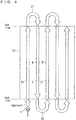
- a flight mode of the unmanned helicopter 1 at a field 52 will be outlined.
- the field 52 is rectangular.
- an end point of a first outgoing path X1 and a start point of a return path Y are connected with each other by a first U-turn path Z1; an end point of the return path Y and a start point of a second outgoing path X2 are connected with each other by a second U-turn path Z2; and thereafter, the same procedure is repeated.
- a substantially constant space (spray width) W is provided between a mutually adjacent outgoing path and a return path.
- the space W is changeable as necessary.
- the start point and the end point are set on a corresponding end line of the field 52. Therefore, typically, a chemical agent is sprayed from the start point to the end point of the outgoing path and the return path but no spraying of the chemical agent is made in the U-turn path.
- the unmanned helicopter 1 is flown straight forward in a direction in which it is to be flown straightly; once the start point of the first outgoing path X1 is reached, the unmanned helicopter 1 is flown straight forward from the start point to the end point of the first outgoing path X1 (from one of the end lines to the other of the end lines of the field 52) at a constant height while spraying the chemical agent.
- the unmanned helicopter 1 is turned along the first U-turn path Z1, to the start point of the next spray target, i.e. , the return path Y; the unmanned helicopter 1 is then flown straight forward from the start point to the end point of the return path Y at a constant height while spraying the chemical agent.
- the unmanned helicopter 1 is turned along the second U-turn path Z2, to the start point of the next spray target, i.e., the second outgoing path X2; the unmanned helicopter 1 is then flown straight forward from the start point to the end point of the second outgoing path X2 at a constant height while spraying the chemical agent. Thereafter, the same sequence is repeated.
- the chemical agent was sprayed from the start point to the end point of each of the outgoing path and the return path (from end to end of the field 52).
- the present invention is not limited to this.
- spraying of the chemical agent may be started at a further inward point of the field 52 than the start point.
- the orientation sensor 44 represents the orientation detection section.
- the GPS antenna 40 and the GPS receiver section 42 represent the speed information detection section.
- the CPU 34a control section 34
- the memory 34b represents the storage section.
- the first stick-like member 16a and the second stick-like member 16b represent the steering section.
- the spray switch 30 represents the spray instruction section. In the semi-automatic flight mode, the spray switch 30 also functions as the end point instruction section. In the incomplete full-automatic flight mode, the turn switch 32 also functions as the end point instruction section.
- the distance W represents the first space information and the second space information.
- Fig. 4 Fig. 5 and Fig. 6
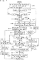
- the description will cover an example of a semi-automatic flight mode of the unmanned helicopter 1.
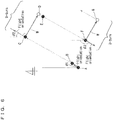
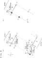
- Fig. 6 , Fig. 8 and Fig. 10 show black circles (•), each indicating a position of the unmanned helicopter 1 when the human operator made a switch in the operation.
- Step S1 the operator turns the turn direction changing switch 28 to the left position or the right position, thereby setting the direction for the U-turn of the unmanned helicopter 1 on the ground (Step S1).
- the turn direction changing switch 28 is set to the right position.
- the transmitter 12 is operated, whereby the unmanned helicopter 1 takes off and normal flight control is performed (Step S3).
- the unmanned helicopter 1 is brought to a hovering state with the nose aligned with a direction in which the operator wants to make it spray, or is flown in a direction in which the spraying operation is planned; then the process waits for the operator to turn ON the Turn Assist start switch 26 (Step S5).
- Step S7 determines whether or not the unmanned helicopter 1 is in a hovering state. If the unmanned helicopter 1 is in a hovering state, Position A and the nose orientation as "flight orientation" are stored in the memory 34b (Step S9) . On the other hand, if the unmanned helicopter 1 is moving, Position A and a traveling orientation as "flight orientation" are stored in the memory 34b (Step S11). In this way, Position A and "flight orientation" are stored in the memory 34b as information concerning the base point. In the present embodiment, as shown in Fig.
- the "flight orientation” is indicated as an angle with respect to the north as a reference; and an angle ⁇ 1 is stored in the memory 34b as "flight orientation” at the base point. Then, along the "flight orientation” and passing through Position A, a straight flight path (including an arrow with a broken line on the left side in Fig. 6 (the first outgoing path X1)) is set.
- the unmanned helicopter 1 flies along the "flight orientation" from Position A while automatically accelerating to a preset “spray speed” and reaches the "spray speed” (Step S13). Simultaneously, by using speed information (in terms of the up-down direction) from the GPS satellites 50, a control for maintaining a flight altitude at this moment is started.
- Step S15 a determination is made as to whether or not the operator has turned ON the spray switch 30 (Step S15). Until the operator turns ON the spray switch 30, the unmanned helicopter 1 maintains the flight at the "spray speed". Once the spray switch 30 is turned ON at Position B in Fig. 6 , for example, spraying of the chemical agent from the unmanned helicopter 1 is started from Position B. Thereafter, determination is made as to whether or not the operator has turned OFF the spray switch 30 (Step S17). The spraying of the chemical agent is continued until the spray switch 30 is turned OFF. When the spray switch 30 is turned OFF at Position C in Fig. 6 for example, the spraying of the chemical agent is stopped, and Position C is taken as the end point of the first outgoing path X1.
- Position C The flight of the unmanned helicopter 1 from Position B to Position C is controlled so that the relative position with respect to the base point (Position A) is along the flight path while constant "spray speed" and flight altitude are maintained. Further, when the spray switch 30 is turned OFF, a relative position at Position C (end point of the first outgoing path X1) with respect to the base point (Position A), and a traveling orientation at Position C as "flight orientation" are stored in the memory 34b (Step S19). As for "flight orientation", an angle ⁇ 2 is stored in the memory 34b. Therefore, Position C is the latest base point now.
- Step S21 a relative position with respect to the most recent base point (Position A) and a "flight orientation" at Position C are overwritten in the memory 34b as the information concerning the base point. Then, a U-turn of the unmanned helicopter 1 is started in the turning direction which was set in Step S1 (Step S21).
- Position D is a target position which is spaced from Position C by a predetermined distance (space W) perpendicular from the "flight orientation" at Position C.
- Step S27 the flight path is changed by 180° (Step S27), and the process returns to Step S15.
- Step 15 if the spray switch 30 is turned ON at Position E shown in Fig. 6 for example, spraying of the chemical agent from the unmanned helicopter 1 is started at Position E. It should be noted here that the timing of spraying the chemical agent may be before reaching Position D or upon reaching Position D. Thereafter, determination is made as to whether or not the operator has turned OFF the spray switch 30 (Step S17). The spraying of the chemical agent is continued until the spray switch 30 is turned OFF. When the spray switch 30 is turned OFF at Position F in Fig.
- Position F is taken as the end point of the return path Y: a relative position at Position F (end point of the return path Y) with respect to the most recent base point (Position C), and a traveling orientation at Position F as "flight orientation" are stored in the memory 34b (Step S19).
- a relative position at Position F end point of the return path Y
- a traveling orientation at Position F as "flight orientation” are stored in the memory 34b (Step S19).
- an angle ⁇ 3 is stored in the memory 34b. Therefore, Position F is now the latest base point.
- a relative position at Position F with respect to the most recent base point (Position C) and a "flight orientation” are overwritten in the memory 34b as the information concerning the base point.
- a U-turn of the unmanned helicopter 1 is started in the turning direction which was set in Step S1 (Step S21).
- Position G is a target position which is spaced from Position F by a predetermined distance (space W) perpendicular from the "flight orientation" at Position F.
- a flight path from Position G (indicated by an arrow with a broken line on the right side in Fig. 6 ) is set for traveling in the reverse direction, i.e., at an angle of 180 degrees from the "flight orientation" at Position F stored in the memory 34b; and automatic control is provided so that the flight of the unmanned helicopter 1 occurs along the given flight path.
- the flight path is changed by 180° (Step S27), and the process returns to Step S15.
- Step S15 through Step S27 is repeated as needed.
- Step S29 When the operator turns OFF the Turn Assist start switch 26, the semi-automatic flight mode is coercively terminated (Step S29), the spraying of the chemical agent is stopped, the unmanned helicopter 1 is brought to a stand-by hovering state (Step S31), and the process returns to Step S3.
- a relative position which indicates a position of the unmanned helicopter 1 with respect to the base point, is detected based on the flight orientation of the unmanned helicopter 1, and the flight distance of the unmanned helicopter 1 which is obtained by integrating the speed information, and the unmanned helicopter 1 performs its flight based on the relative position. Therefore, even in a case where a series of flights must be made over areas of different topography, it is not necessary to spend time for cumbersome preparation and setting before the flight, and the task can be performed easily and flexibly.
- a position of the unmanned helicopter 1 at one time point during the flight of the unmanned helicopter 1 is taken as a base point; a flight path for the unmanned helicopter 1 to fly is set based on a flight orientation of the unmanned helicopter 1 at the base point; and the unmanned helicopter 1 makes its flight so that its relative position is along the flight path. Therefore, it is not necessary to set a flight path(s) in advance. The operator should simply operate to set an appropriate position as the base point while watching the unmanned helicopter 1 in flight, and then, it is possible to fly the unmanned helicopter 1 along the flight path.
- a position of the unmanned helicopter 1 at a time point when the Turn Assist start switch 26 is used to give an instruction to start Turn Assist is set as the base point; in the first outgoing path X1, the unmanned helicopter 1 is flown along the flight orientation at the base point; in the first U-turn path Z1, the start point of the return path Y is detected based on the flight orientation of the unmanned helicopter 1 at the end point of the first outgoing path X1 and the space W to move the unmanned helicopter 1 from the end point of the first outgoing path X1 to the start point of the return path Y; and in the return path Y, the unmanned helicopter 1 is flown in the reverse direction from the flight orientation at the end point of the first outgoing path X1.
- the unmanned helicopter 1 performs a round trip so that the first outgoing path X1 and the return path Y are parallel to each other with the space W in between. Also, in the first U-turn path Z1 and the return path Y, the unmanned helicopter 1 is flown based on the most recent flight orientation at the end point of the first outgoing path X1; therefore, it is possible to fly the unmanned helicopter 1 so that the first outgoing path X1 and the return path Y are more parallel to each other.
- the start point of the second outgoing path X2 is detected based on the flight orientation of the unmanned helicopter 1 at the end point of the return path Y and the space W, whereby the unmanned helicopter 1 is moved from the end point of the return path Y to the start point of the second outgoing path X2.
- the unmanned helicopter 1 is flown in the reverse direction from the flight orientation at the end point of the return path Y. Therefore, it is possible to easily make the flight fit a given flight area by repeating the flight pattern from the first outgoing path X1 to the second outgoing path X2 as needed.
- the unmanned helicopter 1 is flown based on the flight orientation at the end point of the return path Y; therefore, it is possible to fly the unmanned helicopter 1 so that the return path Y and the second outgoing path X2 are more parallel to each other.
- the first outgoing path X1 and the second outgoing path X2 are on opposite sides from each other with respect to the return path Y, and the space W between the first outgoing path X1 and the return path Y is substantially equal to the space W between the return path Y and the second outgoing path X2. Therefore, it is possible to easily make the unmanned helicopter 1 perform round trips so that the outgoing path and the return path Y are parallel to each other with a substantially constant space in between.
- the flight state of the unmanned helicopter 1 is adjusted if the operated amounts of the first stick-like member 16a and the second stick-like member 16b are within a threshold value T, whereas Turn Assist is terminated if the operated amount of the first stick-like member 16a or the second stick-like member 16b exceeds the threshold value T.
- an operator of any skill level can satisfactorily spray the chemical agent in the field 52. This improves the spraying quality and the spraying efficiency. Particularly when spraying chemical agents to tall crops (pine trees, sugar cane, dent corn, etc.) over a predetermined area from a specified high altitude, it is extremely difficult to exactly repeat a movement flight of a spray width at the specified high altitude. However, the Turn Assist function improves spraying quality/spraying efficiency, leading to increased operability.
- speed information which indicates a current speed of the unmanned helicopter 1 is extracted, and the speed information is integrated to obtain a flight distance. Based on the flight distance and the flight orientation, a relative position which indicates a position of the unmanned helicopter 1 with respect to the base point is detected. This can give more accurate position information than position information obtained directly from the GPS signals.
- the start point of the return path Y is detected based on the flight orientation of the unmanned helicopter 1 at the end point of the first outgoing path X1 which was given by the spray switch 30 that functions also as the end point instruction section, and on the space W; and the start point of the second outgoing path X2 is detected based on the flight orientation of the unmanned helicopter 1 at the end point of the return path Y given by the spray switch 30, and on the space W.
- the spray switch 30 functions as both the spray instruction section and the end point instruction section; spraying of the chemical agent is started in response to an instruction to start spraying from the spray switch 30 and the spraying of the chemical agent is terminated in response to an instruction to terminate the spraying from the spray switch 30, upon which the start point of the return path Y and the start point of the second outgoing path X2 are detected. Since the spray switch 30 functions also as the end point instruction section as described above, there is no need for providing a separate end point instruction section other than the spray switch 30.
- Limits may be set in advance on the number of turns and/or a total transverse distance of movement (sum of spaces W), with an arrangement that the semi-automatic flight mode is automatically terminated and changed to the hovering state if the limit is exceeded. This can prevent operation mistakes by the operator.
- the operator turns the turn direction changing switch 28 to the left position or the right position, thereby determining the direction for the U-turn of the unmanned helicopter 1 on the ground, and turns ON the turn switch 32, thereby selecting the complete full-automatic flight mode (Step S101).
- the turn direction changing switch 28 is set to the right position.
- the "spray distance" (the distance from Position B to Position D, and the distance from Position E to Position G, in Fig. 8(a) ) as the distance information, and the number of turns are set in advance. It should be noted here that the "spray distance" and the number of turns may be set at this time point, or previous values may be used.
- Step S103 the unmanned helicopter 1 takes off and normal flight control is performed.
- the unmanned helicopter 1 is brought to a hovering state with the nose aligned with a direction in which the operator wants to make it spray, or is flown in a direction in which the spraying operation is planned; then the process waits for the operator to turn ON the Turn Assist start switch 26 (Step S105). If the Turn Assist start switch 26 is turned ON at Position A shown in Fig. 8(a) for example, the process determines whether or not the unmanned helicopter 1 is in a hovering state (Step S107).
- Position A and the nose orientation as "flight orientation” are stored in the memory 34b (Step S109).
- Position A and a traveling orientation as "flight orientation” are stored in the memory 34b (Step S111).
- Position A and "flight orientation” are stored in the memory 34b as information concerning a base point.
- An angle ⁇ 1 is stored in the memory 34b as "flight orientation” at the base point.
- Step S113 the unmanned helicopter 1 flies along the "flight orientation" while automatically accelerating to a preset "spray speed" (> "turn preparation speed") (Step S113). Simultaneously, by using the speed information (in terms of the up-down direction) from the GPS satellites 50, control for maintaining a flight altitude at this moment is started.
- the unmanned helicopter 1 automatically starts spraying of the chemical agent from Position B (start point of the first outgoing path X1), and calculates the distance moved from Position B on the fly (Step S115). Thereafter, determination is made as to whether or not the turn switch 32 is in the ON state (Step S117). Since the turn switch 32 was set to the ON state in Step S101, determination in the first outgoing path X1 is that the turn switch 32 is in the ON state, and the process goes to Step S119, which determines whether or not the unmanned helicopter 1 has moved from Position B by an amount (which is equal to the preset amount of spray distance minus a turn preparation distance).
- the turn preparation distance is set in advance. Until the unmanned helicopter 1 has moved by the amount (which is equal to the preset amount of spray distance minus the turn preparation distance), the flight at the "spray speed" is continued; once movement by the said amount of the distance has been made, the unmanned helicopter 1 decelerates to the turn preparation speed to prepare for the U-turn (Step S121). As understood, deceleration to the turn preparation speed is performed without operation by the operator once the unmanned helicopter 1 has moved from Position B to Position C in Fig. 8(a) .
- the unmanned helicopter 1 makes the U-turn using the same procedure as has been described for the semi-automatic flight mode. Specifically, in the following U-turn in the first U-turn path Z1, automatic control is performed so that the unmanned helicopter 1 makes a turn without changing the nose direction, while making an arc toward Position E (start point of the return path Y) shown in Fig. 8 (a) and completes acceleration to the "spray speed" by the time Position E is reached (Step S129).
- Position E is a target position which is spaced from Position D by a predetermined distance (space W) perpendicular from the "flight orientation" at Position D.
- a flight path from Position E (indicated by an arrow with a broken line in the middle of Fig. 8 (a) (representing Return Path Y)) is set for traveling in the reverse direction, i.e., at an angle of 180 degrees from the "flight orientation" at Position D stored in the memory 34b; and automatic control is provided so that the flight of the unmanned helicopter 1 occurs along the given flight path.
- the flight path is changed by 180° (Step S133), and the process returns to Step S115.
- Step S115 the unmanned helicopter 1 automatically starts spraying of the chemical agent from Position E in Fig. 8 (a) , and continues the flight while calculating the distance moved from Position E. Thereafter, determination is made as to whether or not the turn switch 32 is in the ON state (Step S117); if it is in the ON state, then determination is made as to whether or not the unmanned helicopter 1 has moved from Position E by the amount (which is equal to the preset amount of spray distance minus the turn preparation distance) (Step S119).
- Step S121 deceleration to the turn preparation speed is performed without operation by the operator once the unmanned helicopter 1 has moved from Position E to Position F in Fig. 8(a) .
- Step S127 a relative position at Position G with respect to the most recent base point (Position D) and a "flight orientation" are overwritten in the memory 34b as the information concerning the base point. Then, a U-turn of the unmanned helicopter 1 is started in the turning direction which was set in Step S101 (Step S127). As described, without need for operation by the operator, the spraying of the chemical agent is continued until Position G (end point of the return path Y) in Fig. 8(a) is reached, and then the U-turn is started.
- Position H is a target position which is spaced by a predetermined distance (space W) from Position G perpendicular from the "flight orientation" at Position G.
- a flight path from Position H (indicated by an arrow with a broken line on the right side in Fig. 8 (a) ) is set for traveling in the reverse direction, i.e., at an angle of 180 degrees from the "flight orientation" at Position G stored in the memory 34b; and automatic control is provided so that the flight of the unmanned helicopter 1 occurs along the given flight path.
- the flight path is changed by 180° (Step S133), and the process returns to Step S115. Thereafter, the same procedure as described above is performed to detect the end point of the second outgoing path X2.
- Step S1305 the turn switch 32 is turned OFF at Position I in Step S117; then deceleration is made to the turn preparation speed for U-turn preparation (Step S135). Thereafter, as far as the turn switch 32 is not turned back to the ON state (Step S137; NO), the unmanned helicopter 1 continues its flight at the turn preparation speed; and once the turn switch 32 is turned ON at Position J (Step S137; YES), for example, the process goes to Step S123, and the spraying of the chemical agent is stopped.
- Position J is picked as the end point of the second outgoing path X2; and a relative position at Position J (end point of the second outgoing path X2) with respect to the most recent base point (Position G), and a traveling orientation at Position J as "flight orientation” are stored in the memory 34b (Step S125).
- a relative position at Position J with respect to the most recent base point (Position G) and a "flight orientation” are overwritten in the memory 34b as the information concerning the base point.
- Step S127 the "spray distance" i.e., turn position is adjusted.
- Step S139 the complete full-automatic flight mode is coercively terminated
- Step S141 the spraying of the chemical agent is terminated
- Step S141 the unmanned helicopter 1 is brought to a stand-by hovering state
- Step S141 the process returns to Step S103. Otherwise, the above-described process is repeated until the unmanned helicopter 1 has made the U-turns for "the number of turns", whereupon the spraying of the chemical agent is terminated, and the unmanned helicopter 1 is brought to a hovering state.
- the Turn Assist start switch 26 gives an instruction to start Turn Assist as a trigger, whereupon the start point of the first outgoing path X1 is detected; the end point of the first outgoing path X1 is detected based on the start point of the first outgoing path X1 and a preset "spray distance"; and the start point of the return path Y is detected based on the flight orientation of the unmanned helicopter 1 at the end point of the first outgoing path X1 and the space W.
- the operator can change start/stop timing of U-turns and spraying and the spray distance by operating the turn switch 32.
- Limits may be set in advance on the number of turns and/or a total longitudinal or transverse distance of movement, with an arrangement that the complete full-automatic flight mode is automatically terminated and changed to the hovering state if the limit is exceeded. This can prevent operation mistakes by the operator.
- the operator turns the turn direction changing switch 28, to the left position or the right position, thereby determining the direction for the U-turn of the unmanned helicopter 1 on the ground, and turns OFF the turn switch 32, thereby selecting incomplete full-automatic flight mode (Step S201).
- the turn direction changing switch 28 is set to the right position.
- the number of turns is set in advance. It should be noted here that the number of turns may be set at this time point, or a previous value may be used.
- Step S203 the unmanned helicopter 1 takes off and normal flight control is performed.
- the unmanned helicopter 1 is brought to a hovering state with the nose aligned with a direction in which the operator wants to make it spray, or is flown in a direction in which the spraying operation is planned; then the process waits for the operator to turn ON the Turn Assist start switch 26 (Step S205). If the Turn Assist start switch 26 is turned ON at Position A shown in Fig. 10 for example, the process determines whether or not the unmanned helicopter 1 is in a hovering state (Step S207).
- Position A and the nose orientation as "flight orientation” are stored in the memory 34b (Step S209).
- Position A and a traveling orientation as "flight orientation” are stored in the memory 34b (Step S211).
- Position A and "flight orientation” are stored in the memory 34b as information concerning a base point.
- An angle ⁇ 1 is stored in the memory 34b as "flight orientation” at the base point.
- the unmanned helicopter 1 flies along the "flight path” while automatically accelerating to a preset “turn preparation speed” ( ⁇ "spray speed”) (Step S213). Simultaneously, by using the speed information (in terms of the up-down direction) from the GPS satellites 50, control for maintaining a flight altitude at this moment is started. It should be noted here that the "turn preparation speed" is slower than the "spray speed” so as to allow quick response to a U-turn instruction and start a U-turn.
- the unmanned helicopter 1 automatically starts spraying of the chemical agent from the Position B (start point of the first outgoing path X1), and calculates the distance moved from Position B on the fly (Step S215). Thereafter, determination is made as to whether or not the turn switch 32 is in the ON state (Step S217). Since the turn switch 32 is set to the OFF state in Step S201, it is determined that the turn switch 32 is in the OFF state in the first outgoing path X1; the process goes to Step S219 and continues the flight at the turn preparation speed. The state is maintained unless the turn switch 32 is turned ON (Step S221; NO).
- Step S221; YES When the turn switch 32 is turned ON at Position C in Fig. 10(a) (Step S221; YES), for example, the spraying of the chemical agent is stopped (Step S223); Position C is picked as the end point of the first outgoing path X1; and a relative position at Position C (end point of the first outgoing path X1) with respect to the base point (Position A), and a traveling orientation at Position C as "flight orientation" are stored in the memory 34b (Step S225). As for "flight orientation", an angle ⁇ 2 is stored in the memory 34b. Therefore, Position C is picked as the latest base point.
- Position D is a target position which is spaced by a predetermined distance (space W) from Position C perpendicular from the "flight orientation" at Position C.
- Step S231 a flight path from Position D (indicated by an arrow with a middle broken line in Fig. 10(a) (representing Return Path Y)) is set for traveling in the reverse direction, i.e., at an angle of 180 degrees from the "flight orientation" at Position C stored in the memory 34b; and automatic control is provided so that the flight of the unmanned helicopter 1 is performed along the given flight path.
- the flight path is changed by 180° (Step S233), and the process returns to Step S215.
- Step S215 the unmanned helicopter 1 automatically starts spraying of the chemical agent from Position D in Fig. 10(a) , and continues the flight while calculating the distance moved from Position D. Thereafter, determination is made as to whether or not the turn switch 32 is in the ON state (Step S217); if it is in the ON state, then determination is made as to whether or not the unmanned helicopter 1 has moved by an amount (which is equal to the stored amount of spray distance minus the turn preparation distance) from Position D (Step S235).
- Step S237 deceleration to the turn preparation speed is performed once the unmanned helicopter 1 has moved from Position D to Position E in Fig. 10(a) .
- Step S227 a relative position at Position F with respect to the most recent base point (Position C) and a "flight orientation" are overwritten in the memory 34b as the information concerning the base point. Then, a U-turn of the unmanned helicopter 1 is started in the turning direction which was set in Step S201 (Step S227). As described, once the turn switch 32 is turned ON in Step S221, the spraying of the chemical agent is continued from Position D (start point of the return path Y) to Position F (end point of the return path Y) in Fig. 10(a) , and then the U-turn is started without any operation by the operator.
- Position G is a target position which is spaced by a predetermined distance (space W) from Position F perpendicular from the "flight orientation" at Position F.
- a flight path from Position G (indicated by an arrow with a broken line on the right side in Fig. 10 (a) ) is set for traveling in the reverse direction, i.e. , at an angle of 180 degrees from the "flight orientation" at Position F stored in the memory 34b; and automatic control is provided so that the flight of the unmanned helicopter 1 is performed along the given flight path.
- the flight path is changed by 180° (Step S233), and the process returns to Step S215. Thereafter, the same procedure as described above is performed to detect the end point of the second outgoing path X2.
- Step S219 the turn preparation speed for U-turn preparation.
- the unmanned helicopter 1 continues its flight at the turn preparation speed; and once the turn switch 32 is turned ON at Position I (Step S221; YES), for example, the process goes to Step S223, and the spraying of the chemical agent is stopped.
- Position I is picked as the end point of the second outgoing path X2; and a relative position at Position I (end point of the second outgoing path X2) with respect to the most recent base point (Position F), and a traveling orientation at Position I as "flight orientation” are stored in the memory 34b (Step S225).
- a relative position at Position I with respect to the most recent base point (Position F) and a "flight orientation” are overwritten in the memory 34b as the information concerning the base point.
- Step S2207 the changed "spray distance" (distance from Position G to Position I) is overwritten in the memory 34b. Then, a U-turn of the unmanned helicopter 1 is started in the turning direction which was set in Step S201 (Step S227). As described above, the "spray distance", i.e., turn position is adjusted.
- Step S239 when the operator turns OFF the Turn Assist start switch 26 to interrupt the process, the incomplete full-automatic flight mode is coercively terminated (Step S239); the spraying of the chemical agent is terminated; the unmanned helicopter 1 is brought to a stand-by hovering state (Step S241); and the process returns to Step S203. Otherwise, the above-described process is repeated until the unmanned helicopter 1 has made a U-turn for "the number of turns", whereupon the spraying of the chemical agent is terminated, and the unmanned helicopter 1 is brought to a hovering state.
- the Turn Assist start switch 26 gives an instruction to start Turn Assist, which triggers detection of the start point of the first outgoing path X1; the "spray distance" is detected based on the start point of the first outgoing path X1 and the end point of the first outgoing path X1 instructed by the turn switch 32; and the start point of the return path Y is detected based on the flight orientation of the unmanned helicopter 1 at the end point of the first outgoing path X1 and the space W.
- Spraying of the chemical agent is started at each start point of the first outgoing path X1, the return path Y and the second outgoing path X2; and the spraying of the chemical agent is terminated at each end point of the first outgoing path X1, the return path Y and the second outgoing path X2.
- the end point of the first outgoing path X1 is indicated by the turn switch 32, the "spray distance" is detected, and based on the detected "spray distance", the end point of the return path Y and the end point of the second outgoing path X2 are also detected. Therefore, the distance for which the chemical agent is sprayed (spray stop timing) in the first outgoing path X1, the return path Y and the second outgoing path X2 can be easily set (changed) by instructions from the operator.
- the operator can change start/stop timing of U-turn and spraying and the spray distance by operating the turn switch 32.
- Limits may be set in advance on the number of turns and/or a total longitudinal or transverse distance of movement, with an arrangement that the incomplete full-automatic flight mode is automatically terminated and changed to the hovering state if the limit is exceeded. This can prevent operation mistakes by the operator.
- the start point of the return path Y is detected based on the flight orientation of the unmanned helicopter 1 at the end point of the first outgoing path X1 and the space W.
- the start point of the return path Y may be detected based on the flight orientation of the unmanned helicopter 1 at the base point or any position in the first outgoing path X1 and the space W.
- the start point of the second outgoing path X2 is detected based on the flight orientation of the unmanned helicopter 1 at the end point of the return path Y and the space W.
- the start point of the second outgoing path X2 may be detected based on the flight orientation of the unmanned helicopter 1 at the base points or any position in the first outgoing path X1 or the return path Y and the space W.
- the unmanned helicopter 1 in the return path Y, is flown in the reverse direction from the flight orientation at the end point of the first outgoing path X1.
- the invention is not limited to this.
- the unmanned helicopter 1 may be flown in the reverse direction from the flight orientation at the base point or any position in the first outgoing path X1.
- the unmanned helicopter 1 in the second outgoing path X2, is flown in the reverse direction from the flight orientation at the end point of the return path Y.
- the invention is not limited to this.
- the unmanned helicopter 1 may be flown along the flight orientation at the base point or any position in the first outgoing path X1, or the unmanned helicopter 1 may be flown in the reverse direction from the flight orientation at any position in the return path Y.
- the spray instruction section functions also as the end point instruction section.
- the invention is not limited to this.
- the spray instruction section and the end point instruction section may be separate members from each other.
- first outgoing path X1 and the second outgoing path X2 are on opposite sides from each other with respect to the return path Y.
- the first outgoing path X1 and the second outgoing path X2 may be on the same side with respect to the return path Y.
- the space between the second outgoing path X2 and the return path Y is approximately two times or half of the space between the first path and the return path Y.
- Speed information of the unmanned helicopter 1 may be obtained from a speed sensor, a Pitot tube, etc. mounted on the unmanned helicopter 1. Also, speed information of the unmanned helicopter 1 may be obtained by integrating acceleration information from a gyro sensor mounted on the unmanned helicopter 1. In these cases, it is possible to obtain desired information without relying on the GPS satellites 50.
- the unmanned helicopter 1 may change the nose direction by 180° when making a U-turn.
- the spray speed is adjustable as needed.
- the spray material is provided by a chemical agent.
- the spray material may be provided by fertilizers, seeds, etc.
- the information concerning the base point is updated, and based on the updated information concerning the base point, a relative position with respect to the base point is detected for a point (e.g. end point of the outgoing path or of the return path).
- a point e.g. end point of the outgoing path or of the return path.
- the invention is not limited to this. There may be an arrangement that the information concerning the first base point is not updated, and a relative position of a point with respect to the base point is detected based on the information concerning the first base point.
- the base point includes not only a base point as position information but also a base point as time information.
Landscapes
- Engineering & Computer Science (AREA)
- Aviation & Aerospace Engineering (AREA)
- Remote Sensing (AREA)
- Radar, Positioning & Navigation (AREA)
- Physics & Mathematics (AREA)
- General Physics & Mathematics (AREA)
- Automation & Control Theory (AREA)
- Mechanical Engineering (AREA)
- Life Sciences & Earth Sciences (AREA)
- Pest Control & Pesticides (AREA)
- Computer Networks & Wireless Communication (AREA)
- Chemical & Material Sciences (AREA)
- Combustion & Propulsion (AREA)
- Mathematical Physics (AREA)
- Computing Systems (AREA)
- Theoretical Computer Science (AREA)
- Catching Or Destruction (AREA)
- Control Of Position, Course, Altitude, Or Attitude Of Moving Bodies (AREA)
- Toys (AREA)
- Navigation (AREA)
- Position Fixing By Use Of Radio Waves (AREA)
Abstract
Description
- The present invention relates to remote control devices, and more specifically to a remote control device of an unmanned helicopter.
- An example of conventional techniques in this field is disclosed in
Patent Literature 1.Patent Literature 1 discloses a flight planning apparatus which makes it possible to set flight area data by moving on an outer circumference of a planned flight area with a GPS receiver connected therewith and registering absolute positions (positions expressed by longitude and latitude) and altitudes given by the GPS receiver at each end point of the flight area. - Patent Literature 1:
JP-A 2002-211494 - However, according to the flight planning apparatus, it is necessary to register absolute positions and altitudes given by the GPS receiver at every end point of the flight area while moving on an outer circumference of the flight area, and this must be done for each flight area, so cumbersome steps are required in preparation and setting before the flight.
- Therefore, a primary object of the present invention is to provide a remote control device that enables a desired flight of an unmanned helicopter without requiring cumbersome steps in preparation and setting before the flight regardless of topography of the flight area.
- According to an aspect of the present invention, there is provided a remote control device for an unmanned helicopter, including an orientation detection section which detects a flight orientation of the unmanned helicopter; a speed information detection section which detects speed information of the unmanned helicopter; a distance detection section which detects a flight distance of the unmanned helicopter by integrating the speed information; a storage section which stores information about the unmanned helicopter concerning an updatable base point; a position detection section which detects a relative position that indicates a position of the unmanned helicopter with respect to the base point based on the flight orientation of the unmanned helicopter and the flight distance of the unmanned helicopter obtained by integrating the speed information; and a control section which controls a flight of the unmanned helicopter based on the relative position.
- In the present invention, regardless of the topography of the flight area, a relative position, which indicates a position of the unmanned helicopter with respect to the base point, is detected based on the flight orientation of the unmanned helicopter and the flight distance of the unmanned helicopter which is obtained by integrating the speed information, and the unmanned helicopter performs its flight based on the relative position. Therefore, even in a case where a series of flights must be made over areas of different topography, it is not necessary to spend time for cumbersome preparation and setting before the flight, and the task can be performed easily and flexibly. In other words, the unmanned helicopter does not require cumbersome steps in the preparation and setting before the flight regardless of topography of the flight area, and enables a desired flight.
- Preferably, the control section causes the storage section to store the flight orientation of the unmanned helicopter at a time point during the flight of the unmanned helicopter as the information concerning the base point; sets a flight path for the unmanned helicopter to fly based on the flight orientation at the base point; and controls the flight of the unmanned helicopter so that the relative position is along the flight path. In this case, a position of the unmanned helicopter at one time point during the flight is taken as a base point; a flight path for the unmanned helicopter to fly is set based on a flight orientation of the unmanned helicopter at the base point; and the unmanned helicopter performs its flight so that its relative position is along the flight path. Therefore, it is not necessary to set a flight path(s) in advance. The operator should simply operate to set an appropriate position as the base point while watching the unmanned helicopter in flight, and then, it is possible to fly the unmanned helicopter along the flight path.
- Further preferably, the remote control device further includes an instruction section which gives an instruction to start Turn Assist of the unmanned helicopter as a flight mode in which a traveling direction is automatically changed. With this arrangement, in order to fly the unmanned helicopter along the flight path including a first outgoing path, a return path and a first U-turn path which connects an end point of the first outgoing path and a start point of the return path with each other, the control section causes the storage section to store a position and a flight orientation of the unmanned helicopter at a time point when the instruction section gives the instruction to start Turn Assist, as the information concerning the base point; causes the unmanned helicopter to fly along the flight orientation at the base point, in the first outgoing path; causes the unmanned helicopter to move from the end point of the first outgoing path to the start point of the return path by detecting the start point of the return path based on the flight orientation of the unmanned helicopter at the base point or in the first outgoing path and first space information which indicates a space between the first outgoing path and the return path, in the first U-turn path; and causes the unmanned helicopter to fly in a reverse direction from the flight orientation at the base point or in the first outgoing path, in the return path. In this case, when flying the unmanned helicopter along a flight path which includes the first outgoing path, the return path and the first U-turn path connecting the two paths with each other, the position of the unmanned helicopter at a time point when the instruction section gives an instruction to start Turn Assist is set as the base point; in the first outgoing path, the unmanned helicopter is flown along the flight orientation at the base point; in the first U-turn path, the start point of the return path is detected based on the flight orientation of the unmanned helicopter at the base point or in the first outgoing path and the first space information to move the unmanned helicopter from the end point of the first outgoing path to the start point of the return path; and in the return path, the unmanned helicopter is flown in the reverse direction from the flight orientation at the base point or in the first outgoing path. Therefore, by giving the instruction to start Turn Assist with the instruction section, it is possible to easily make the unmanned helicopter perform a round trip so that the first outgoing path and the return path are parallel to each other with the space indicated by the first space information.
- Further, preferably, the control section: causes the unmanned helicopter to move from the end point of the first outgoing path to the start point of the return path by detecting the start point of the return path based on the flight orientation of the unmanned helicopter at the end point of the first outgoing path and the first space information, in the first U-turn path and causes the unmanned helicopter to fly in a reverse direction from the flight orientation at the end point of the first outgoing path, in the return path. In this case, in the first U-turn path and the return path, the unmanned helicopter is flown based on the most recent flight orientation at the end point of the first outgoing path. Therefore, it is possible to fly the unmanned helicopter so that the first outgoing path and the return path are more parallel to each other.
- Preferably, the flight path further includes a second outgoing path and a second U-turn path which connects an end point of the return path and a start point of the second outgoing path with each other. With this arrangement, the control section: causes the unmanned helicopter to move from the end point of the return path to the start point of the second outgoing path by detecting the start point of the second outgoing path based on the flight orientation of the unmanned helicopter at the base point, in the first outgoing path or in the return path and second space information which indicates a space between the return path and the second outgoing path, in the second U-turn path; and causes the unmanned helicopter to fly along the flight orientation at the base point or in the first outgoing path, or causes the unmanned helicopter to fly in a reverse direction from the flight orientation in the return path, in the second outgoing path. In this case, it is possible to easily make the flight fit a given flight area by repeating the flight pattern from the first outgoing path to the second outgoing path as needed.
- Further preferably, the control section causes the unmanned helicopter to move from the end point of the return path to the start point of the second outgoing path by detecting the start point of the second outgoing path based on the flight orientation of the unmanned helicopter at the end point of the return path and the second space information, in the second U-turn path; and causes the unmanned helicopter to fly in a reverse direction from the flight orientation at the end point of the return path, in the second outgoing path. In this case, in the second U-turn path and the second outgoing path, the unmanned helicopter is flown based on the most recent flight orientation at the end point of the return path. Therefore, it is possible to fly the unmanned helicopter so that the return path and the second outgoing path are more parallel to each other.
- Further, preferably, the remote control device further includes an end point instruction section which gives instructions of the end point of the first outgoing path and of the end point of the return path. With this arrangement, the control section detects the start point of the return path based on the flight orientation of the unmanned helicopter at the end point of the first outgoing path indicated in the instruction by the end point instruction section and the first space information, and detects the start point of the second outgoing path based on the flight orientation of the unmanned helicopter at the end point of the return path indicated in the instruction by the end point instruction section and the second space information. In this case, it is possible to give instructions of the end point of the first outgoing path and of the end point of the return path by the end point instruction section, and therefore, it is possible to freely set the distance from the start point of the first outgoing path to the end point thereof, and the distance from the start point of the return path to the end point thereof. In other words, it is possible to set the timing for the U-turn of the unmanned helicopter with the instruction from the human operator. Therefore, it is possible to easily adapt the flight to various topographic differences (depth of the site) in the flight area.
- Preferably, the unmanned helicopter is utilized for spraying a spray material, and the remote control device further comprises a spray instruction section for instructions to start and terminate spraying of the spray material. With this arrangement, the spray instruction section works also as the end point instruction section; the control section starts the spraying of the spray material in response to the instruction to start the spraying from the spray instruction section; and terminates the spraying of the spray material and detects the start point of the return path and the start point of the second outgoing path, in response to the instruction to terminate the spraying from the spray instruction section. In this case, there is no need to provide a separate end point instruction section other than the spray instruction section since the spray instruction section works also as the end point instruction section. Further, spraying of the spray material from the unmanned helicopter is started in response to the instruction to start the spraying from the spray instruction section, and the spraying of the spray material from the unmanned helicopter is terminated in response to the instruction to terminate the spraying from the spray instruction section. Therefore, it is not necessary to store a spray distance in advance; rather, the operator can flexibly start/stop the spraying with his/her own instruction at appropriate positions while watching the position of the unmanned helicopter in flight.
- Further preferably, the control section detects the start point of the first outgoing path, triggered by the instruction to start Turn Assist from the instruction section; detects the end point of the first outgoing path based on the start point of the first outgoing path and distance information which is set in advance; and detects the start point of the return path based on the flight orientation of the unmanned helicopter at the end point of the first outgoing path and the first space information; and further, the control section detects the end point of the return path based on the start point of the return path and the distance information which is set in advance; detects the start point of the second outgoing path based on the flight orientation of the unmanned helicopter at the end point of the return path and the second space information; and detects the end point of the second outgoing path based on the start point of the second outgoing path and the distance information which is set in advance. In this case, by giving the instruction to start Turn Assist using the instruction section, it is possible, thereafter, to automatically fly the unmanned helicopter.
- Further, preferably, the unmanned helicopter is utilized for spraying a spray material, and the control section starts spraying of the spray material at each start point of the first outgoing path, the return path and the second outgoing path; and terminates the spraying of the spray material at each end point of the first outgoing path, the return path and the second outgoing path. In this case, the operator does not have to give instructions to start or terminate the spraying since starting and terminating of the spraying of the spray material are performed automatically.
- Preferably, the remote control device further includes an end point instruction section which gives an instruction of the end point of the first outgoing path. With this arrangement, the control section detects the start point of the first outgoing path, triggered by the instruction to start Turn Assist from the instruction section; detects distance information based on the start point of the first outgoing path and the end point of the first outgoing path indicated in the instruction by the end point instruction section; and detects the start point of the return path based on the flight orientation of the unmanned helicopter at the end point of the first outgoing path and the first space information; and further, the control section detects the end point of the return path based on the start point of the return path and the detected distance information; detects the start point of the second outgoing path based on the flight orientation of the unmanned helicopter at the end point of the return path and the second space information; and detects the end point of the second outgoing path based on the start point of the second outgoing path and the detected distance information. In this case, by indicating the end point of the first outgoing path using the end point instruction section, it is possible to set (change) the distance from the start point of the first outgoing path to the end point thereof, the distance from the start point of the return path to the end point thereof, and the distance from the start point of the second outgoing path to the end point thereof, namely, the timings for the U-turns of the unmanned helicopter. Therefore, it is possible to easily adapt the flight to various topographic differences (depth of the site) in the flight area.
- Further preferably, the unmanned helicopter is utilized for spraying a spray material, and the control section starts spraying of the spray material at each start point of the first outgoing path, the return path and the second outgoing path; and terminates the spraying of the spray material at each end point of the first outgoing path, the return path and the second outgoing path. Here, for example, in an incomplete full-automatic flight mode which will be described later, when the end point of the first outgoing path is indicated by the end point instruction section, distance information is detected, and based on the distance information, the end point of the return path and the end point of the second outgoing path are also detected. Therefore, the distance for which the spray material is sprayed (spray stop timing) in the first outgoing path, the return path and the second outgoing path can be set (changed) easily with instructions from the operator.
- Further, preferably, the first outgoing path and the second outgoing path are on opposite sides from each other with respect to the return path, and the space between the first outgoing path and the return path is substantially equal to the space between the return path and the second outgoing path. In this case, it is possible to easily make the unmanned helicopter perform a round trip so that the outgoing path and the return path are parallel to each other with a substantially constant space in between.
- Preferably, the remote control device further includes a steering section which steers the unmanned helicopter. With this arrangement, the control section adjusts a flight state of the unmanned helicopter if an amount of operation of the steering section is within a threshold value, or terminates Turn Assist if the amount of operation of the steering section exceeds the threshold value, after the instruction is given to start Turn Assist. In this case, the operator can make fine adjustment, during the flight along the flight path, on the flight state (flight route) while watching the unmanned helicopter, and the operator can terminate the flight along the flight path immediately and easily if the flight state is very much different from a desired one.
- The above-described object and other objects, characteristics, aspects and advantages of the present invention will become clearer from the following detailed description of embodiments of the present invention to be made with reference to the attached drawings.
-
-
Fig. 1 is an illustrative drawing which shows a remote control device and an unmanned helicopter according to an embodiment of the present invention. -
Fig. 2 is an electrical block diagram which shows a configuration example of the remote control device. -
Fig. 3 is an illustrative drawing for describing movement of a first stick-like member and a second stick-like member and a threshold value. -
Fig. 4 is an illustrative drawing which outlines a flight mode of the unmanned helicopter. -
Fig. 5 is a flowchart which shows an example of semi-automatic flight mode. -
Fig. 6 is an illustrative drawing which outlines the semi-automatic flight mode. -
Fig. 7 is a flowchart which shows an example of complete full-automatic flight mode. -
Fig. 8 is an illustrative drawing which outlines the complete full-automatic flight mode. -
Fig. 9 is a flowchart which shows an example of incomplete full-automatic flight mode. -
Fig. 10 is an illustrative drawing which outlines the incomplete full-automatic flight mode. - Hereinafter, embodiments of the present invention will be described with reference to the drawings.
- Referring to
Fig. 1 , aremote control device 10 according to an embodiment of the present invention is a remote control device of anunmanned helicopter 1. - The
unmanned helicopter 1 includes abody 2, amast 3, amain rotor 4 and atail rotor 5. Themast 3 protrudes upward from thebody 2, and is rotatable. Themast 3 has an upper end portion, where themain rotor 4 is fixed. Thetail rotor 5 is rotatable, and is at a rear end portion of thebody 2. Themain rotor 4 and thetail rotor 5 are rotated based on a driving force from an unillustrated drive source provided inside thebody 2. Also, theunmanned helicopter 1 has an unillustrated spray apparatus for spraying a spray material such as a chemical agent. - The
remote control device 10 includes atransmitter 12 which transmits signals toward theunmanned helicopter 1, and acomponent 14 which is installed in theunmanned helicopter 1. - Referring to
Fig. 2 , thetransmitter 12 includes a first stick-like member 16a, a second stick-like member 16b, asignal generation section 18, aCPU 20, a high-frequency section 22, atransmission antenna 24, a Turn Assist startswitch 26, a turndirection changing switch 28 and aspray switch 30. - Referring to
Fig. 1 , the first stick-like member 16a and the second stick-like member 16b represent the steering section for steering theunmanned helicopter 1. Operating the first stick-like member 16a in direction ab (fore-aft direction) controls a motor 48 (which will be described later), to change an angle of the nose in an up-down direction during the flight, whereby theunmanned helicopter 1 accelerates or decelerates (moves forward or moves backward). Operating the first stick-like member 16a in the direction a moves down the nose to cause theunmanned helicopter 1 to accelerate (fly forward), whereas operating the first stick-like member 16a in the direction b moves up the nose to cause theunmanned helicopter 1 to decelerate (fly backward). Operating the first stick-like member 16a in direction cd (left-right direction) turns the nose in the left-right direction. Operating the second stick-like member 16b in direction ef (fore-aft direction) causes the helicopter body to ascend or descend. Operating the second stick-like member 16b in direction gh (left-right direction) causes the helicopter body to tilt in the left-right direction. - Referring to
Fig. 3 , as described above, the first stick-like member 16a and the second stick-like member 16b are movable (tiltable) from a baseline position SP (neutral position), to forward, rearward, leftward and rightward. Thecomponent 14 includes a control section 34 (to be described later) which, after the Turn Assist startswitch 26 of thetransmitter 12 is turned ON whereby an instruction to start Turn Assist is given, adjusts the flight state (flight route) of theunmanned helicopter 1 in accordance with an amount of operation (operation angle X) of the first stick-like member 16a and the second stick-like member 16b from the baseline position SP if the amount of operation is within a threshold value T, or terminates the Turn Assist if the amount of operation of the first stick-like member 16a and the second stick-like member 16b exceeds the threshold value T. - The
signal generation section 18 of thetransmitter 12 generates analog operation information in accordance with the amount of operation of the first stick-like member 16a and/or the second stick-like member 16b from their baseline positions SP. TheCPU 20 converts the given analog operation information into digital operation information, and sends it to the high-frequency section 22. - The Turn Assist start
switch 26 of thetransmitter 12 represents the instruction section which gives an instruction to start Turn Assist of theunmanned helicopter 1. Turn Assist means setting to a flight mode in which a traveling direction is automatically changed. As examples of the flight mode in which the traveling direction is automatically changed, a semi-automatic flight mode, a complete full-automatic flight mode and an incomplete full-automatic flight mode will be described later. Upon turning ON the Turn Assist startswitch 26, an instruction to start Turn Assist is given to the control section 34 of thecomponent 14, whereupon a memory 34b (to be described later) of the control section 34 stores a nose orientation (direction in which the nose faces) or traveling orientation (direction in which movement is being made) of theunmanned helicopter 1 as the flight orientation, and theunmanned helicopter 1 starts to accelerate automatically in the flight orientation. Upon turning OFF the Turn Assist startswitch 26, Turn Assist is coercively terminated; spraying of the spray material is terminated; and theunmanned helicopter 1 is brought to a hovering state. - The turn
direction changing switch 28 is a three-position (middle, right and left) switch. The middle position represents a mode in which no Turn Assist is provided, the right position represents a right turn mode, and the left position represents a left turn mode. If a switch is made from the right position or the left position to the middle position during Turn Assist, Turn Assist is terminated and theunmanned helicopter 1 is brought into a hovering state. - When the
spray switch 30 is turned ON, spraying is started, whereas when thespray switch 30 is turned OFF, the spraying is stopped. Thespray switch 30 can also function as a trigger to start a turn. In this case, when thespray switch 30 is turned OFF, spraying is stopped and then a turn is started. - The
transmitter 12 may further include aturn switch 32. The turn switch 32 is utilized when performing the complete full-automatic flight mode or the incomplete full-automatic flight mode which will be described later. When theturn switch 32 is in ON state, it is set to the complete full-automatic flight mode, whereas it is set to the incomplete full-automatic flight mode when it is in OFF state. Also, if theturn switch 32 is turned to ON from OFF, a U-turn is performed, whereas if it is turned OFF from ON, flying speed is decreased to a turn preparation speed (to a turn-position adjustment state). - Signals from these switches are supplied to the
CPU 20. TheCPU 20 converts the supplied signals to digital operation information and sends it to the high-frequency section 22. - In the high-
frequency section 22, modulation is performed by using the digital operation information, and an obtained radio signal is transmitted from thetransmission antenna 24. - The
component 14 includes the control section 34, areception antenna 36, a high-frequency section 38, aGPS antenna 40, aGPS receiver section 42, anorientation sensor 44, amotor driving section 46 and themotor 48. - The radio signal which is sent from the
transmission antenna 24 of thetransmitter 12 is received by thereception antenna 36, and then demodulated by the high-frequency section 38 into digital operation information which represents the amount of operation, and the information is supplied to the control section 34. Also, GPS signals relevant to thehelicopter 1 fromGPS satellites 50 are received by theGPS antenna 40 and supplied to theGPS receiver section 42. In theGPS receiver section 42, speed information which indicates a current speed of theunmanned helicopter 1 is extracted from the supplied GPS signals. The speed information is supplied to the control section 34. Also, theorientation sensor 44 detects a flight orientation of theunmanned helicopter 1. An orientation detection signal is supplied to the control section 34. - The control section 34 includes a
CPU 34a and the memory 34b. TheCPU 34a (control section 34) executes programs stored in the memory 34b, and gives instructions to various constituent elements, thereby controlling thehelicopter 1. For example, theCPU 34a (control section 34) generates control information based on the supplied operation information and speed information and controls themotor driving section 46, so that themotor driving section 46 drives themotor 48. Driving of themotor 48 changes the angle of themain rotor 4 for adjusting the in-flight angle of the nose of theunmanned helicopter 1 in the up-down direction and so on, whereby the flight state is controlled. Also, theCPU 34a (control section 34) integrates the supplied speed information to detect a flight distance of theunmanned helicopter 1. Further, theCPU 34a (control section 34) detects a relative position, which indicates a position of theunmanned helicopter 1 with respect to a base point, based on the flight orientation of theunmanned helicopter 1 and the flight distance of theunmanned helicopter 1 which is obtained through the integration of the speed information, and controls the flight ofunmanned helicopter 1 based on the relative position. Specifically, flight orientations and flight distances are detected at certain time intervals from the base point; based on a flight orientation at the base point and a flight distance after the certain time interval from the base point, a relative position from the base point is detected; then based on a flight orientation at this relative position and a flight distance after the certain time interval from that relative position, a position achieved by the movement from that relative position is detected; and by sequentially adding the position which was moved from the relative position, to the relative position from the base point at the certain time intervals, the relative position with respect to the base point is detected (updated). For example, in a case where theunmanned helicopter 1 is to be maintained at a constant flight altitude, a two-dimensional coordinates may be assumed with the first base point represented by the point of origin (0, 0), the east-west direction represented by the X axis and the north-south direction represented by the Y axis, so that the flight orientation and the flight distance will give the relative position in terms of coordinates (x, y). As another example, a three-dimensional coordinates may be assumed with the first base point represented by the point of origin (0, 0, 0), the east-west direction represented by the X axis, the north-south direction represented by the Y axis and the vertical direction represented by the Z axis, so that the flight orientation and the flight distance will give the relative position in terms of coordinates (x, y, z). The memory 34b stores information etc. at an updatable base point of theunmanned helicopter 1. - Referring to
Fig. 4 , a flight mode of theunmanned helicopter 1 at afield 52 will be outlined. In this example, thefield 52 is rectangular. In a flight path which will be described later, an end point of a first outgoing path X1 and a start point of a return path Y are connected with each other by a first U-turn path Z1; an end point of the return path Y and a start point of a second outgoing path X2 are connected with each other by a second U-turn path Z2; and thereafter, the same procedure is repeated. Between a mutually adjacent outgoing path and a return path, there is provided a substantially constant space (spray width) W. Preferably, the space W is changeable as necessary. In each outgoing path and return path, the start point and the end point are set on a corresponding end line of thefield 52. Therefore, typically, a chemical agent is sprayed from the start point to the end point of the outgoing path and the return path but no spraying of the chemical agent is made in the U-turn path. - First, in an approach, the
unmanned helicopter 1 is flown straight forward in a direction in which it is to be flown straightly; once the start point of the first outgoing path X1 is reached, theunmanned helicopter 1 is flown straight forward from the start point to the end point of the first outgoing path X1 (from one of the end lines to the other of the end lines of the field 52) at a constant height while spraying the chemical agent. Next, theunmanned helicopter 1 is turned along the first U-turn path Z1, to the start point of the next spray target, i.e. , the return path Y; theunmanned helicopter 1 is then flown straight forward from the start point to the end point of the return path Y at a constant height while spraying the chemical agent. Further, theunmanned helicopter 1 is turned along the second U-turn path Z2, to the start point of the next spray target, i.e., the second outgoing path X2; theunmanned helicopter 1 is then flown straight forward from the start point to the end point of the second outgoing path X2 at a constant height while spraying the chemical agent. Thereafter, the same sequence is repeated. It should be noted here that in the above-described example, the chemical agent was sprayed from the start point to the end point of each of the outgoing path and the return path (from end to end of the field 52). However, the present invention is not limited to this. For example, in the outgoing paths and/or the return paths, spraying of the chemical agent may be started at a further inward point of thefield 52 than the start point. - In the present embodiment, the
orientation sensor 44 represents the orientation detection section. TheGPS antenna 40 and theGPS receiver section 42 represent the speed information detection section. TheCPU 34a (control section 34) represents the distance detection section and the position detection section. The memory 34b represents the storage section. The first stick-like member 16a and the second stick-like member 16b represent the steering section. Thespray switch 30 represents the spray instruction section. In the semi-automatic flight mode, thespray switch 30 also functions as the end point instruction section. In the incomplete full-automatic flight mode, theturn switch 32 also functions as the end point instruction section. The distance W represents the first space information and the second space information. - Next, referring to
Fig. 4 ,Fig. 5 andFig. 6 , the description will cover an example of a semi-automatic flight mode of theunmanned helicopter 1. It should be noted here thatFig. 6 ,Fig. 8 andFig. 10 show black circles (•), each indicating a position of theunmanned helicopter 1 when the human operator made a switch in the operation. - First, the operator turns the turn
direction changing switch 28 to the left position or the right position, thereby setting the direction for the U-turn of theunmanned helicopter 1 on the ground (Step S1). In the case shown inFig. 6 , the turndirection changing switch 28 is set to the right position. Next, thetransmitter 12 is operated, whereby theunmanned helicopter 1 takes off and normal flight control is performed (Step S3). In this process, theunmanned helicopter 1 is brought to a hovering state with the nose aligned with a direction in which the operator wants to make it spray, or is flown in a direction in which the spraying operation is planned; then the process waits for the operator to turn ON the Turn Assist start switch 26 (Step S5). If the Turn Assist startswitch 26 is turned ON at Position A shown inFig. 6 , for example, the process determines whether or not theunmanned helicopter 1 is in a hovering state (Step S7). If theunmanned helicopter 1 is in a hovering state, Position A and the nose orientation as "flight orientation" are stored in the memory 34b (Step S9) . On the other hand, if theunmanned helicopter 1 is moving, Position A and a traveling orientation as "flight orientation" are stored in the memory 34b (Step S11). In this way, Position A and "flight orientation" are stored in the memory 34b as information concerning the base point. In the present embodiment, as shown inFig. 6 , the "flight orientation" is indicated as an angle with respect to the north as a reference; and an angle θ1 is stored in the memory 34b as "flight orientation" at the base point. Then, along the "flight orientation" and passing through Position A, a straight flight path (including an arrow with a broken line on the left side inFig. 6 (the first outgoing path X1)) is set. Theunmanned helicopter 1 flies along the "flight orientation" from Position A while automatically accelerating to a preset "spray speed" and reaches the "spray speed" (Step S13). Simultaneously, by using speed information (in terms of the up-down direction) from theGPS satellites 50, a control for maintaining a flight altitude at this moment is started. - Then, a determination is made as to whether or not the operator has turned ON the spray switch 30 (Step S15). Until the operator turns ON the
spray switch 30, theunmanned helicopter 1 maintains the flight at the "spray speed". Once thespray switch 30 is turned ON at Position B inFig. 6 , for example, spraying of the chemical agent from theunmanned helicopter 1 is started from Position B. Thereafter, determination is made as to whether or not the operator has turned OFF the spray switch 30 (Step S17). The spraying of the chemical agent is continued until thespray switch 30 is turned OFF. When thespray switch 30 is turned OFF at Position C inFig. 6 for example, the spraying of the chemical agent is stopped, and Position C is taken as the end point of the first outgoing path X1. The flight of theunmanned helicopter 1 from Position B to Position C is controlled so that the relative position with respect to the base point (Position A) is along the flight path while constant "spray speed" and flight altitude are maintained. Further, when thespray switch 30 is turned OFF, a relative position at Position C (end point of the first outgoing path X1) with respect to the base point (Position A), and a traveling orientation at Position C as "flight orientation" are stored in the memory 34b (Step S19). As for "flight orientation", an angle θ2 is stored in the memory 34b. Therefore, Position C is the latest base point now. As described above, a relative position with respect to the most recent base point (Position A) and a "flight orientation" at Position C are overwritten in the memory 34b as the information concerning the base point. Then, a U-turn of theunmanned helicopter 1 is started in the turning direction which was set in Step S1 (Step S21). - In the U-turn in the first U-turn path Z1, automatic control is performed so that the
unmanned helicopter 1 makes a turn without changing the nose direction, while making an arc toward Position D (start point of the return path Y) shown inFig. 6 and completes acceleration to the "spray speed" by the time Position D is reached (Step S23). Herein, Position D is a target position which is spaced from Position C by a predetermined distance (space W) perpendicular from the "flight orientation" at Position C. Once theunmanned helicopter 1 arrives at the target position, i.e., Position D (start point of the return path Y) (Step S25), a flight path from Position D (indicated by an arrow with a broken line in the middle ofFig. 6 (representing the return path Y)) is set for traveling in the reverse direction, i.e., at an angle of 180 degrees from the "flight orientation" at Position C stored in the memory 34b; and automatic control is provided so that the flight of theunmanned helicopter 1 occurs along the given flight path. As described above, the flight path is changed by 180° (Step S27), and the process returns to Step S15. - In
Step 15, if thespray switch 30 is turned ON at Position E shown inFig. 6 for example, spraying of the chemical agent from theunmanned helicopter 1 is started at Position E. It should be noted here that the timing of spraying the chemical agent may be before reaching Position D or upon reaching Position D. Thereafter, determination is made as to whether or not the operator has turned OFF the spray switch 30 (Step S17). The spraying of the chemical agent is continued until thespray switch 30 is turned OFF. When thespray switch 30 is turned OFF at Position F inFig. 6 , for example, the spraying of the chemical agent is stopped, and Position F is taken as the end point of the return path Y: a relative position at Position F (end point of the return path Y) with respect to the most recent base point (Position C), and a traveling orientation at Position F as "flight orientation" are stored in the memory 34b (Step S19). As for "flight orientation", an angle θ3 is stored in the memory 34b. Therefore, Position F is now the latest base point. As described above, a relative position at Position F with respect to the most recent base point (Position C) and a "flight orientation" are overwritten in the memory 34b as the information concerning the base point. Then, a U-turn of theunmanned helicopter 1 is started in the turning direction which was set in Step S1 (Step S21). - In the U-turn in the second U-turn path Z2, automatic control is performed so that the
unmanned helicopter 1 makes a turn without changing the nose direction, while making an arc toward Position G (start point of the second outgoing path X2) shown inFig. 6 and completes acceleration to the "spray speed" by the time Position G is reached (Step S23). Herein, Position G is a target position which is spaced from Position F by a predetermined distance (space W) perpendicular from the "flight orientation" at Position F. Once theunmanned helicopter 1 arrives at the target position, i.e., Position G (start point of the second outgoing path X2) (Step S25), a flight path from Position G (indicated by an arrow with a broken line on the right side inFig. 6 ) is set for traveling in the reverse direction, i.e., at an angle of 180 degrees from the "flight orientation" at Position F stored in the memory 34b; and automatic control is provided so that the flight of theunmanned helicopter 1 occurs along the given flight path. As described above, the flight path is changed by 180° (Step S27), and the process returns to Step S15. - The above-described process from Step S15 through Step S27 is repeated as needed.
- As an interruption to the process, the following is performed. When the operator turns OFF the Turn Assist start
switch 26, the semi-automatic flight mode is coercively terminated (Step S29), the spraying of the chemical agent is stopped, theunmanned helicopter 1 is brought to a stand-by hovering state (Step S31), and the process returns to Step S3. - According to the
remote control device 10 which functions as described above, regardless of the topography of the flight area, a relative position, which indicates a position of theunmanned helicopter 1 with respect to the base point, is detected based on the flight orientation of theunmanned helicopter 1, and the flight distance of theunmanned helicopter 1 which is obtained by integrating the speed information, and theunmanned helicopter 1 performs its flight based on the relative position. Therefore, even in a case where a series of flights must be made over areas of different topography, it is not necessary to spend time for cumbersome preparation and setting before the flight, and the task can be performed easily and flexibly. - A position of the
unmanned helicopter 1 at one time point during the flight of theunmanned helicopter 1 is taken as a base point; a flight path for theunmanned helicopter 1 to fly is set based on a flight orientation of theunmanned helicopter 1 at the base point; and theunmanned helicopter 1 makes its flight so that its relative position is along the flight path. Therefore, it is not necessary to set a flight path(s) in advance. The operator should simply operate to set an appropriate position as the base point while watching theunmanned helicopter 1 in flight, and then, it is possible to fly theunmanned helicopter 1 along the flight path. - When flying the
unmanned helicopter 1 along a flight path which includes the first outgoing path X1, the return path Y and the first U-turn path Z1 connecting the two paths with each other, a position of theunmanned helicopter 1 at a time point when the Turn Assist startswitch 26 is used to give an instruction to start Turn Assist is set as the base point; in the first outgoing path X1, theunmanned helicopter 1 is flown along the flight orientation at the base point; in the first U-turn path Z1, the start point of the return path Y is detected based on the flight orientation of theunmanned helicopter 1 at the end point of the first outgoing path X1 and the space W to move theunmanned helicopter 1 from the end point of the first outgoing path X1 to the start point of the return path Y; and in the return path Y, theunmanned helicopter 1 is flown in the reverse direction from the flight orientation at the end point of the first outgoing path X1. Therefore, by giving the instruction to start Turn Assist with the Turn Assist startswitch 26, it is possible to easily make theunmanned helicopter 1 perform a round trip so that the first outgoing path X1 and the return path Y are parallel to each other with the space W in between. Also, in the first U-turn path Z1 and the return path Y, theunmanned helicopter 1 is flown based on the most recent flight orientation at the end point of the first outgoing path X1; therefore, it is possible to fly theunmanned helicopter 1 so that the first outgoing path X1 and the return path Y are more parallel to each other. - In the second U-turn path Z2, the start point of the second outgoing path X2 is detected based on the flight orientation of the
unmanned helicopter 1 at the end point of the return path Y and the space W, whereby theunmanned helicopter 1 is moved from the end point of the return path Y to the start point of the second outgoing path X2. In the second outgoing path X2, theunmanned helicopter 1 is flown in the reverse direction from the flight orientation at the end point of the return path Y. Therefore, it is possible to easily make the flight fit a given flight area by repeating the flight pattern from the first outgoing path X1 to the second outgoing path X2 as needed. Also, in the second U-turn path Z2 and the second outgoing path X2, theunmanned helicopter 1 is flown based on the flight orientation at the end point of the return path Y; therefore, it is possible to fly theunmanned helicopter 1 so that the return path Y and the second outgoing path X2 are more parallel to each other. - The first outgoing path X1 and the second outgoing path X2 are on opposite sides from each other with respect to the return path Y, and the space W between the first outgoing path X1 and the return path Y is substantially equal to the space W between the return path Y and the second outgoing path X2. Therefore, it is possible to easily make the
unmanned helicopter 1 perform round trips so that the outgoing path and the return path Y are parallel to each other with a substantially constant space in between. - After the instruction is given to start Turn Assist, the flight state of the
unmanned helicopter 1 is adjusted if the operated amounts of the first stick-like member 16a and the second stick-like member 16b are within a threshold value T, whereas Turn Assist is terminated if the operated amount of the first stick-like member 16a or the second stick-like member 16b exceeds the threshold value T. This allows the operator, during the flight along the flight path, to make fine adjustments to the flight state (flight route) while watching theunmanned helicopter 1, and the operator can terminate the flight along the flight path immediately and easily if the flight state is very much different from a desired one. - Also, an operator of any skill level can satisfactorily spray the chemical agent in the
field 52. This improves the spraying quality and the spraying efficiency. Particularly when spraying chemical agents to tall crops (pine trees, sugar cane, dent corn, etc.) over a predetermined area from a specified high altitude, it is extremely difficult to exactly repeat a movement flight of a spray width at the specified high altitude. However, the Turn Assist function improves spraying quality/spraying efficiency, leading to increased operability. - Further, from GPS signals, speed information which indicates a current speed of the
unmanned helicopter 1 is extracted, and the speed information is integrated to obtain a flight distance. Based on the flight distance and the flight orientation, a relative position which indicates a position of theunmanned helicopter 1 with respect to the base point is detected. This can give more accurate position information than position information obtained directly from the GPS signals. - The above-described functions and advantages are provided not only in semi-automatic flight mode but also in complete full-automatic flight mode and incomplete full-automatic flight mode which will be described later.
- Also, according to the semi-automatic flight mode, the start point of the return path Y is detected based on the flight orientation of the
unmanned helicopter 1 at the end point of the first outgoing path X1 which was given by thespray switch 30 that functions also as the end point instruction section, and on the space W; and the start point of the second outgoing path X2 is detected based on the flight orientation of theunmanned helicopter 1 at the end point of the return path Y given by thespray switch 30, and on the space W. Thus, it is possible to give instructions of the end point of the first outgoing path X1 and of the end point of the return path Y by using thespray switch 30, and therefore, it is possible to freely set the distance from the start point of the first outgoing path X1 to the end point thereof, and the distance from the start point of the return path Y to the end point thereof. In other words, it is possible to set the timing for U-turn of theunmanned helicopter 1 with the instruction from the operator. Therefore, it is possible to easily adapt the flight to various topographic differences (depth of the site) in the flight area. - The
spray switch 30 functions as both the spray instruction section and the end point instruction section; spraying of the chemical agent is started in response to an instruction to start spraying from thespray switch 30 and the spraying of the chemical agent is terminated in response to an instruction to terminate the spraying from thespray switch 30, upon which the start point of the return path Y and the start point of the second outgoing path X2 are detected. Since thespray switch 30 functions also as the end point instruction section as described above, there is no need for providing a separate end point instruction section other than thespray switch 30. Further, in response to the instruction to start spraying from thespray switch 30, spraying of the chemical agent from theunmanned helicopter 1 is started, whereas in response to the instruction to terminate the spraying from thespray switch 30, the spraying of the chemical agent from theunmanned helicopter 1 is terminated. Therefore, it is not necessary to store a spray distance in advance; rather, the operator can flexibly start/stop the spraying with his/her own instruction at appropriate positions while watching the position of theunmanned helicopter 1 in flight. Further, since the operator can change the spray distance through his/her own operation, it is possible to handle situations easily and flexibly even in cases where a chemical agent is sprayed in thefields 52 of different shapes. - Limits may be set in advance on the number of turns and/or a total transverse distance of movement (sum of spaces W), with an arrangement that the semi-automatic flight mode is automatically terminated and changed to the hovering state if the limit is exceeded. This can prevent operation mistakes by the operator.
- Next, Referring to
Fig. 4 ,Fig. 7 andFig. 8 , description will be made of an example of a complete full-automatic flight mode of theunmanned helicopter 1. - First, the operator turns the turn
direction changing switch 28 to the left position or the right position, thereby determining the direction for the U-turn of theunmanned helicopter 1 on the ground, and turns ON theturn switch 32, thereby selecting the complete full-automatic flight mode (Step S101). In the case shown inFig. 8 , the turndirection changing switch 28 is set to the right position. In the complete full-automatic flight mode, the "spray distance" (the distance from Position B to Position D, and the distance from Position E to Position G, inFig. 8(a) ) as the distance information, and the number of turns are set in advance. It should be noted here that the "spray distance" and the number of turns may be set at this time point, or previous values may be used. - Next, the
transmitter 12 is operated, whereby theunmanned helicopter 1 takes off and normal flight control is performed (Step S103). In this process, theunmanned helicopter 1 is brought to a hovering state with the nose aligned with a direction in which the operator wants to make it spray, or is flown in a direction in which the spraying operation is planned; then the process waits for the operator to turn ON the Turn Assist start switch 26 (Step S105). If the Turn Assist startswitch 26 is turned ON at Position A shown inFig. 8(a) for example, the process determines whether or not theunmanned helicopter 1 is in a hovering state (Step S107). If theunmanned helicopter 1 is in a hovering state, Position A and the nose orientation as "flight orientation" are stored in the memory 34b (Step S109). On the other hand, if theunmanned helicopter 1 is moving, Position A and a traveling orientation as "flight orientation" are stored in the memory 34b (Step S111). In this way, Position A and "flight orientation" are stored in the memory 34b as information concerning a base point. An angle θ1 is stored in the memory 34b as "flight orientation" at the base point. Then, along the "flight orientation" and passing through Position A, a straight flight path (including an arrow with a broken line on the left side inFig. 8 (a) (the first outgoing path X1)) is set: Starting from Position A, theunmanned helicopter 1 flies along the "flight orientation" while automatically accelerating to a preset "spray speed" (> "turn preparation speed") (Step S113). Simultaneously, by using the speed information (in terms of the up-down direction) from theGPS satellites 50, control for maintaining a flight altitude at this moment is started. - Once the
unmanned helicopter 1 achieves the "spray speed" at Position B shown inFig. 8(a) for example, theunmanned helicopter 1 automatically starts spraying of the chemical agent from Position B (start point of the first outgoing path X1), and calculates the distance moved from Position B on the fly (Step S115). Thereafter, determination is made as to whether or not theturn switch 32 is in the ON state (Step S117). Since theturn switch 32 was set to the ON state in Step S101, determination in the first outgoing path X1 is that theturn switch 32 is in the ON state, and the process goes to Step S119, which determines whether or not theunmanned helicopter 1 has moved from Position B by an amount (which is equal to the preset amount of spray distance minus a turn preparation distance). The turn preparation distance is set in advance. Until theunmanned helicopter 1 has moved by the amount (which is equal to the preset amount of spray distance minus the turn preparation distance), the flight at the "spray speed" is continued; once movement by the said amount of the distance has been made, theunmanned helicopter 1 decelerates to the turn preparation speed to prepare for the U-turn (Step S121). As understood, deceleration to the turn preparation speed is performed without operation by the operator once theunmanned helicopter 1 has moved from Position B to Position C inFig. 8(a) . - Then, when the
unmanned helicopter 1 has moved from Position B by the preset amount of spray distance (from Position B to Position D inFig. 8(a) ), the spraying of the chemical agent is stopped (Step S123), and a relative position at Position D (end point of the first outgoing path X1) with respect to the base point (Position A), and a traveling orientation at Position D as "flight orientation" are stored in the memory 34b (Step S125). As for "flight orientation", an angle θ2 is stored in the memory 34b. Therefore, Position D is picked as the latest base point. As described above, a relative position with respect to the most recent base point (Position A) and a "flight orientation" at Position D are overwritten in the memory 34b as the information concerning the base point. Then, the U-turn of theunmanned helicopter 1 is started in the turning direction which was set in Step S101 (Step S127). As described, without any operation by the operator, the spraying of the chemical agent is continued until Position D (end point of the first outgoing path X1) inFig. 8(a) is reached and the U-turn is started. - The
unmanned helicopter 1 makes the U-turn using the same procedure as has been described for the semi-automatic flight mode. Specifically, in the following U-turn in the first U-turn path Z1, automatic control is performed so that theunmanned helicopter 1 makes a turn without changing the nose direction, while making an arc toward Position E (start point of the return path Y) shown inFig. 8 (a) and completes acceleration to the "spray speed" by the time Position E is reached (Step S129). Herein, Position E is a target position which is spaced from Position D by a predetermined distance (space W) perpendicular from the "flight orientation" at Position D. Once theunmanned helicopter 1 arrives at the target position, i.e., Position E (start point of Return Path Y) (Step S131), a flight path from Position E (indicated by an arrow with a broken line in the middle ofFig. 8 (a) (representing Return Path Y)) is set for traveling in the reverse direction, i.e., at an angle of 180 degrees from the "flight orientation" at Position D stored in the memory 34b; and automatic control is provided so that the flight of theunmanned helicopter 1 occurs along the given flight path. As described above, the flight path is changed by 180° (Step S133), and the process returns to Step S115. - In Step S115, the
unmanned helicopter 1 automatically starts spraying of the chemical agent from Position E inFig. 8 (a) , and continues the flight while calculating the distance moved from Position E. Thereafter, determination is made as to whether or not theturn switch 32 is in the ON state (Step S117); if it is in the ON state, then determination is made as to whether or not theunmanned helicopter 1 has moved from Position E by the amount (which is equal to the preset amount of spray distance minus the turn preparation distance) (Step S119). Until theunmanned helicopter 1 has moved by the amount (which is equal to the preset amount of spray distance minus the turn preparation distance), the flight at the "spray speed" is continued; once movement by the said amount of the distance has been made, deceleration to the turn preparation speed is performed to prepare for a U-turn (Step S121). As understood, deceleration to the turn preparation speed is performed without operation by the operator once theunmanned helicopter 1 has moved from Position E to Position F inFig. 8(a) . - Then, when the
unmanned helicopter 1 has moved from Position E by the preset amount of spray distance (from Position E to Position G inFig. 8(a) ), the spraying of the chemical agent is stopped (Step S123), and a relative position at Position G (end point of the return path Y) with respect to the most recent base point (Position D), and a traveling orientation at Position G as "flight orientation" are stored in the memory 34b (Step S125). As for "flight orientation", an angle θ3 is stored in the memory 34b. Therefore, Position G is picked as the latest base point. As described above, a relative position at Position G with respect to the most recent base point (Position D) and a "flight orientation" are overwritten in the memory 34b as the information concerning the base point. Then, a U-turn of theunmanned helicopter 1 is started in the turning direction which was set in Step S101 (Step S127). As described, without need for operation by the operator, the spraying of the chemical agent is continued until Position G (end point of the return path Y) inFig. 8(a) is reached, and then the U-turn is started. - Thereafter, in the U-turn in the second U-turn path Z2, automatic control is performed so that the
unmanned helicopter 1 makes a turn without changing the nose direction, while making an arc toward Position H (start point of the second outgoing path X2) inFig. 8 (a) and completes acceleration to the "spray speed" by the time Position H is reached (Step S129). Herein, Position H is a target position which is spaced by a predetermined distance (space W) from Position G perpendicular from the "flight orientation" at Position G. Once theunmanned helicopter 1 arrives at the target position, i.e., Position H (start point of the second outgoing path X2) (Step S131), a flight path from Position H (indicated by an arrow with a broken line on the right side inFig. 8 (a) ) is set for traveling in the reverse direction, i.e., at an angle of 180 degrees from the "flight orientation" at Position G stored in the memory 34b; and automatic control is provided so that the flight of theunmanned helicopter 1 occurs along the given flight path. As described above, the flight path is changed by 180° (Step S133), and the process returns to Step S115. Thereafter, the same procedure as described above is performed to detect the end point of the second outgoing path X2. - In cases where the "spray distance" is not changed, the above-described process from Step S115 through Step S133 is repeated until "the number of turns" is reached.
- On the other hand, if the "spray distance" is to be changed, the following operation is performed.
- For example, referring to
Fig. 8(b) , in a case where the "spray distance" is changed in the second outgoing path X2, if theturn switch 32 is turned OFF at Position I in Step S117; then deceleration is made to the turn preparation speed for U-turn preparation (Step S135). Thereafter, as far as theturn switch 32 is not turned back to the ON state (Step S137; NO), theunmanned helicopter 1 continues its flight at the turn preparation speed; and once theturn switch 32 is turned ON at Position J (Step S137; YES), for example, the process goes to Step S123, and the spraying of the chemical agent is stopped. Then, Position J is picked as the end point of the second outgoing path X2; and a relative position at Position J (end point of the second outgoing path X2) with respect to the most recent base point (Position G), and a traveling orientation at Position J as "flight orientation" are stored in the memory 34b (Step S125). As for "flight orientation", an angle θ4 is stored in the memory 34b. Therefore, Position J is now the latest base point. As described above, a relative position at Position J with respect to the most recent base point (Position G) and a "flight orientation" are overwritten in the memory 34b as the information concerning the base point. Also, the changed "spray distance" (distance from Position H to Position J) is overwritten in the memory 34b. Then, a U-turn of theunmanned helicopter 1 is started in the turning direction which was set in Step S101 (Step S127). As described above, the "spray distance", i.e., turn position is adjusted. - Thereafter, the same process as described above is followed to obtain Position K, and when the
unmanned helicopter 1 has moved to Position L, then deceleration to the turn preparation speed is performed. - Then, when the operator turns OFF the Turn Assist start
switch 26 to interrupt the process, the complete full-automatic flight mode is coercively terminated (Step S139), the spraying of the chemical agent is terminated, theunmanned helicopter 1 is brought to a stand-by hovering state (Step S141), and the process returns to Step S103. Otherwise, the above-described process is repeated until theunmanned helicopter 1 has made the U-turns for "the number of turns", whereupon the spraying of the chemical agent is terminated, and theunmanned helicopter 1 is brought to a hovering state. - According to the
remote control device 10 operated as described thus far, the Turn Assist startswitch 26 gives an instruction to start Turn Assist as a trigger, whereupon the start point of the first outgoing path X1 is detected; the end point of the first outgoing path X1 is detected based on the start point of the first outgoing path X1 and a preset "spray distance"; and the start point of the return path Y is detected based on the flight orientation of theunmanned helicopter 1 at the end point of the first outgoing path X1 and the space W. Further, the end point of the return path Y is detected based on the start point of the return path Y and the "spray distance"; the start point of the second outgoing path X2 is detected based on the flight orientation of theunmanned helicopter 1 at the end point of the return path Y and the space W; and the end point of the second outgoing path X2 is detected based on the start point of the second outgoing path X2 and the "spray distance". Therefore, by giving the instruction to start Turn Assist using the Turn Assist startswitch 26, it is possible, thereafter, to automatically fly theunmanned helicopter 1. - It is possible to start spraying of the chemical agent at each start point of the first outgoing path X1, the return path Y and the second outgoing path X2, and to terminate the spraying of the chemical agent at each end point of the first outgoing path X1, the return path Y and the second outgoing path X2. Since starting and terminating the spraying of the chemical agent are performed automatically, the operator does not have to give instructions to start or terminate the spraying.
- The operator can change start/stop timing of U-turns and spraying and the spray distance by operating the
turn switch 32. - Since the operator can change the spray distance through his/her own operation, it is possible to handle situations easily and flexibly even in cases where a chemical agent is sprayed in the
fields 52 of different shapes. - Limits may be set in advance on the number of turns and/or a total longitudinal or transverse distance of movement, with an arrangement that the complete full-automatic flight mode is automatically terminated and changed to the hovering state if the limit is exceeded. This can prevent operation mistakes by the operator.
- Further referring to
Fig. 4 ,Fig. 9 andFig. 10 , description will be made of an example of an incomplete full-automatic flight mode of theunmanned helicopter 1. - First, the operator turns the turn
direction changing switch 28, to the left position or the right position, thereby determining the direction for the U-turn of theunmanned helicopter 1 on the ground, and turns OFF theturn switch 32, thereby selecting incomplete full-automatic flight mode (Step S201). In the case shown inFig. 10 , the turndirection changing switch 28 is set to the right position. In incomplete full-automatic flight mode, the number of turns is set in advance. It should be noted here that the number of turns may be set at this time point, or a previous value may be used. - Next, the
transmitter 12 is operated, whereby theunmanned helicopter 1 takes off and normal flight control is performed (Step S203). In this process, theunmanned helicopter 1 is brought to a hovering state with the nose aligned with a direction in which the operator wants to make it spray, or is flown in a direction in which the spraying operation is planned; then the process waits for the operator to turn ON the Turn Assist start switch 26 (Step S205). If the Turn Assist startswitch 26 is turned ON at Position A shown inFig. 10 for example, the process determines whether or not theunmanned helicopter 1 is in a hovering state (Step S207). If theunmanned helicopter 1 is in a hovering state, Position A and the nose orientation as "flight orientation" are stored in the memory 34b (Step S209). On the other hand, if theunmanned helicopter 1 is moving, Position A and a traveling orientation as "flight orientation" are stored in the memory 34b (Step S211). In this way, Position A and "flight orientation" are stored in the memory 34b as information concerning a base point. An angle θ1 is stored in the memory 34b as "flight orientation" at the base point. Then, along the "flight orientation" and passing through Position A, a straight flight path (including an arrow with a broken line on the left side inFig. 10(a) (the first outgoing path X1)) is set. Starting from Position A, theunmanned helicopter 1 flies along the "flight path" while automatically accelerating to a preset "turn preparation speed" (<"spray speed") (Step S213). Simultaneously, by using the speed information (in terms of the up-down direction) from theGPS satellites 50, control for maintaining a flight altitude at this moment is started. It should be noted here that the "turn preparation speed" is slower than the "spray speed" so as to allow quick response to a U-turn instruction and start a U-turn. - Once the
unmanned helicopter 1 achieves the "turn preparation speed" at Position B shown inFig. 10 (a) for example, theunmanned helicopter 1 automatically starts spraying of the chemical agent from the Position B (start point of the first outgoing path X1), and calculates the distance moved from Position B on the fly (Step S215). Thereafter, determination is made as to whether or not theturn switch 32 is in the ON state (Step S217). Since theturn switch 32 is set to the OFF state in Step S201, it is determined that theturn switch 32 is in the OFF state in the first outgoing path X1; the process goes to Step S219 and continues the flight at the turn preparation speed. The state is maintained unless theturn switch 32 is turned ON (Step S221; NO). When theturn switch 32 is turned ON at Position C inFig. 10(a) (Step S221; YES), for example, the spraying of the chemical agent is stopped (Step S223); Position C is picked as the end point of the first outgoing path X1; and a relative position at Position C (end point of the first outgoing path X1) with respect to the base point (Position A), and a traveling orientation at Position C as "flight orientation" are stored in the memory 34b (Step S225). As for "flight orientation", an angle θ2 is stored in the memory 34b. Therefore, Position C is picked as the latest base point. As described above, a relative position at Position C with respect to the most recent base point (Position A) and a "flight orientation" are overwritten in the memory 34b as the information concerning the base point. Then, a U-turn of theunmanned helicopter 1 is started in the turning direction which was set in Step S201 (Step S227). Also, a "spray distance" from Position B to Position C inFig. 10(a) is stored in the memory 34b. The same procedure as has been described for the complete full-automatic flight mode is used for the U-turn and the flight thereafter of theunmanned helicopter 1. - Specifically, In the following U-turn in the first U-turn path Z1, automatic control is performed so that the
unmanned helicopter 1 makes a turn without changing the nose direction, while making an arc toward Position D (start point of the return path Y) shown inFig. 10(a) and achieves the "spray speed" by the time Position D is reached (Step S229). Herein, Position D is a target position which is spaced by a predetermined distance (space W) from Position C perpendicular from the "flight orientation" at Position C. Once theunmanned helicopter 1 arrives at the target position, i.e., Position D (start point of Return Path Y) (Step S231), a flight path from Position D (indicated by an arrow with a middle broken line inFig. 10(a) (representing Return Path Y)) is set for traveling in the reverse direction, i.e., at an angle of 180 degrees from the "flight orientation" at Position C stored in the memory 34b; and automatic control is provided so that the flight of theunmanned helicopter 1 is performed along the given flight path. As described above, the flight path is changed by 180° (Step S233), and the process returns to Step S215. - In Step S215, the
unmanned helicopter 1 automatically starts spraying of the chemical agent from Position D inFig. 10(a) , and continues the flight while calculating the distance moved from Position D. Thereafter, determination is made as to whether or not theturn switch 32 is in the ON state (Step S217); if it is in the ON state, then determination is made as to whether or not theunmanned helicopter 1 has moved by an amount (which is equal to the stored amount of spray distance minus the turn preparation distance) from Position D (Step S235). Until theunmanned helicopter 1 has moved by the amount (which is equal to the stored amount of spray distance minus the turn preparation distance), the flight at the "spray speed" is continued; once movement by the said amount of the distance has been made, deceleration to the turn preparation speed is performed to prepare for a U-turn (Step S237). As understood, deceleration to the turn preparation speed is performed once theunmanned helicopter 1 has moved from Position D to Position E inFig. 10(a) . - Then, when the
unmanned helicopter 1 has moved from Position D by the stored amount of spray distance (from Position D to Position F inFig. 10(a) ), the spraying of the chemical agent is stopped (Step S223), and a relative position at Position F (end point of the return path Y) with respect to the most recent base point (Position C), and a traveling direction at Position F as "flight orientation" are stored in the memory 34b (Step S225). As for "flight orientation", an angle θ3 is stored in the memory 34b. Therefore, Position F is picked as the latest base point. As described above, a relative position at Position F with respect to the most recent base point (Position C) and a "flight orientation" are overwritten in the memory 34b as the information concerning the base point. Then, a U-turn of theunmanned helicopter 1 is started in the turning direction which was set in Step S201 (Step S227). As described, once theturn switch 32 is turned ON in Step S221, the spraying of the chemical agent is continued from Position D (start point of the return path Y) to Position F (end point of the return path Y) inFig. 10(a) , and then the U-turn is started without any operation by the operator. - Thereafter, in the U-turn in the second U-turn path Z2, automatic control is performed so that the
unmanned helicopter 1 makes a turn without changing the nose direction, while making an arc toward Position G (start point of the second outgoing path X2) inFig. 10 (a) and completes acceleration to the "spray speed" by the time Position G is reached (Step S229). Herein, Position G is a target position which is spaced by a predetermined distance (space W) from Position F perpendicular from the "flight orientation" at Position F. Once theunmanned helicopter 1 arrives at the target position, i.e., Position G (start point of the second outgoing path X2) (Step S231), a flight path from Position G (indicated by an arrow with a broken line on the right side inFig. 10 (a) ) is set for traveling in the reverse direction, i.e. , at an angle of 180 degrees from the "flight orientation" at Position F stored in the memory 34b; and automatic control is provided so that the flight of theunmanned helicopter 1 is performed along the given flight path. As described above, the flight path is changed by 180° (Step S233), and the process returns to Step S215. Thereafter, the same procedure as described above is performed to detect the end point of the second outgoing path X2. - In cases where the "spray distance" is not changed, the above-described process in Steps S215, S217, and S223 through S237 is repeated until "the number of turns" is reached.
- On the other hand, if the "spray distance" is to be changed, the following operation is performed.
- For example, referring to
Fig. 10(b) , in a case where the "spray distance" is changed in the second outgoing path X2, if theturn switch 32 is turned OFF at Position H in Step S217; then deceleration is made to the turn preparation speed for U-turn preparation (Step S219). Thereafter, as far as theturn switch 32 is not turned back to the ON state (Step S221; NO), theunmanned helicopter 1 continues its flight at the turn preparation speed; and once theturn switch 32 is turned ON at Position I (Step S221; YES), for example, the process goes to Step S223, and the spraying of the chemical agent is stopped. Then, Position I is picked as the end point of the second outgoing path X2; and a relative position at Position I (end point of the second outgoing path X2) with respect to the most recent base point (Position F), and a traveling orientation at Position I as "flight orientation" are stored in the memory 34b (Step S225). As for "flight orientation", an angle θ4 is stored in the memory 34b. Therefore, Position I is now the latest base point. As described above, a relative position at Position I with respect to the most recent base point (Position F) and a "flight orientation" are overwritten in the memory 34b as the information concerning the base point. Also, the changed "spray distance" (distance from Position G to Position I) is overwritten in the memory 34b. Then, a U-turn of theunmanned helicopter 1 is started in the turning direction which was set in Step S201 (Step S227). As described above, the "spray distance", i.e., turn position is adjusted. - Thereafter, the same process as described above is followed to obtain Position J, and when the
unmanned helicopter 1 has moved to Position K, then deceleration to the turn preparation speed is performed. - Then, when the operator turns OFF the Turn Assist start
switch 26 to interrupt the process, the incomplete full-automatic flight mode is coercively terminated (Step S239); the spraying of the chemical agent is terminated; theunmanned helicopter 1 is brought to a stand-by hovering state (Step S241); and the process returns to Step S203. Otherwise, the above-described process is repeated until theunmanned helicopter 1 has made a U-turn for "the number of turns", whereupon the spraying of the chemical agent is terminated, and theunmanned helicopter 1 is brought to a hovering state. - According to the
remote control device 10 operated as described thus far, the Turn Assist startswitch 26 gives an instruction to start Turn Assist, which triggers detection of the start point of the first outgoing path X1; the "spray distance" is detected based on the start point of the first outgoing path X1 and the end point of the first outgoing path X1 instructed by theturn switch 32; and the start point of the return path Y is detected based on the flight orientation of theunmanned helicopter 1 at the end point of the first outgoing path X1 and the space W. Further, the end point of the return path Y is detected based on the start point of the return path Y and the detected "spray distance"; the start point of the second outgoing path X2 is detected based on the flight orientation of theunmanned helicopter 1 at the end point of the return path Y and the space W; and the end point of the second outgoing path X2 is detected based on the start point of the second outgoing path X2 and the detected "spray distance". Thus, by indicating the end point of the first outgoing path X1 using theturn switch 32, it is possible to set (change) the distance from the start point of the first outgoing path X1 to the end point thereof, the distance from the start point of the return path Y to the end point thereof, and the distance from the start point of the second outgoing path X2 to the end point thereof, namely, timings for a U-turns by theunmanned helicopter 1. Therefore, it is possible to easily adapt the flight to various topographic differences (depth of the site) in theflight area 52. - Spraying of the chemical agent is started at each start point of the first outgoing path X1, the return path Y and the second outgoing path X2; and the spraying of the chemical agent is terminated at each end point of the first outgoing path X1, the return path Y and the second outgoing path X2. Herein, when the end point of the first outgoing path X1 is indicated by the
turn switch 32, the "spray distance" is detected, and based on the detected "spray distance", the end point of the return path Y and the end point of the second outgoing path X2 are also detected. Therefore, the distance for which the chemical agent is sprayed (spray stop timing) in the first outgoing path X1, the return path Y and the second outgoing path X2 can be easily set (changed) by instructions from the operator. - The operator can change start/stop timing of U-turn and spraying and the spray distance by operating the
turn switch 32. - Since it is possible to set (change) the spray distance by operations from the operator, there is no need for storing the spray distance in advance.
- Limits may be set in advance on the number of turns and/or a total longitudinal or transverse distance of movement, with an arrangement that the incomplete full-automatic flight mode is automatically terminated and changed to the hovering state if the limit is exceeded. This can prevent operation mistakes by the operator.
- It should be noted here that in the embodiment described above, the start point of the return path Y is detected based on the flight orientation of the
unmanned helicopter 1 at the end point of the first outgoing path X1 and the space W. However, the invention is not limited to this. The start point of the return path Y may be detected based on the flight orientation of theunmanned helicopter 1 at the base point or any position in the first outgoing path X1 and the space W. - In the embodiment described above, the start point of the second outgoing path X2 is detected based on the flight orientation of the
unmanned helicopter 1 at the end point of the return path Y and the space W. However, the invention is not limited to this. The start point of the second outgoing path X2 may be detected based on the flight orientation of theunmanned helicopter 1 at the base points or any position in the first outgoing path X1 or the return path Y and the space W. - In the embodiment described above, in the return path Y, the
unmanned helicopter 1 is flown in the reverse direction from the flight orientation at the end point of the first outgoing path X1. However, the invention is not limited to this. In the return path Y, theunmanned helicopter 1 may be flown in the reverse direction from the flight orientation at the base point or any position in the first outgoing path X1. - In the embodiment described above, in the second outgoing path X2, the
unmanned helicopter 1 is flown in the reverse direction from the flight orientation at the end point of the return path Y. However, the invention is not limited to this. In the second outgoing path X2, theunmanned helicopter 1 may be flown along the flight orientation at the base point or any position in the first outgoing path X1, or theunmanned helicopter 1 may be flown in the reverse direction from the flight orientation at any position in the return path Y. - In the embodiment described above, description was made for a case in which the spray instruction section functions also as the end point instruction section. However, the invention is not limited to this. The spray instruction section and the end point instruction section may be separate members from each other.
- In the embodiment described above, description was made for a case in which the first outgoing path X1 and the second outgoing path X2 are on opposite sides from each other with respect to the return path Y. However, the invention is not limited to this. The first outgoing path X1 and the second outgoing path X2 may be on the same side with respect to the return path Y. In this case, it is preferable that the space between the second outgoing path X2 and the return path Y is approximately two times or half of the space between the first path and the return path Y.
- Speed information of the
unmanned helicopter 1 may be obtained from a speed sensor, a Pitot tube, etc. mounted on theunmanned helicopter 1. Also, speed information of theunmanned helicopter 1 may be obtained by integrating acceleration information from a gyro sensor mounted on theunmanned helicopter 1. In these cases, it is possible to obtain desired information without relying on theGPS satellites 50. - In the embodiment described above, description was made for a case in which the
unmanned helicopter 1 moves to the target position without changing the nose direction when making a U-turn. However, the invention is not limited to this. Theunmanned helicopter 1 may change the nose direction by 180° when making a U-turn. - It is preferable that the spray speed is adjustable as needed.
- In the embodiment described above, the spray material is provided by a chemical agent. However, the invention is not limited to this. The spray material may be provided by fertilizers, seeds, etc.
- In the embodiment described above, the information concerning the base point is updated, and based on the updated information concerning the base point, a relative position with respect to the base point is detected for a point (e.g. end point of the outgoing path or of the return path). However, the invention is not limited to this. There may be an arrangement that the information concerning the first base point is not updated, and a relative position of a point with respect to the base point is detected based on the information concerning the first base point.
- It should be noted here that the base point includes not only a base point as position information but also a base point as time information.
- The present invention being thus far described in terms of preferred embodiments, it is obvious that these may be varied in many ways within the scope and the spirit of the present invention. The scope of the present invention is only limited by the accompanied claims.
-
- 1
- Unmanned helicopter
- 10
- Remote control device
- 12
- Transmitter
- 14
- Component
- 16a
- First stick-like member
- 16b
- Second stick-like member
- 18
- Signal generation section
- 20
- CPU
- 22, 38
- High-frequency sections
- 24
- Transmission antenna
- 26
- Turn Assist start switch
- 28
- Turn direction changing switch
- 30
- Spray switch
- 32
- Turn switch
- 34
- Control section
- 34a
- CPU
- 34b
- Memory
- 36
- Reception antenna
- 40
- GPS antenna
- 42
- GPS receiver section
- 44
- Orientation sensor
- 46
- Motor driving section
- 48
- Motor
- 50
- GPS satellite
- T
- Threshold value
- SP
- Baseline position
- W
- Space
- X1
- First outgoing path
- X2
- Second outgoing path
- Y
- Return path
Claims (14)
- A remote control device for an unmanned helicopter, comprising:an orientation detection section which detects a flight orientation of the unmanned helicopter;a speed information detection section which detects speed information of the unmanned helicopter;a distance detection section which detects a flight distance of the unmanned helicopter by integrating the speed information;a storage section which stores information about the unmanned helicopter concerning an updatable base point;a position detection section which detects a relative position that indicates a position of the unmanned helicopter with respect to the base point based on the flight orientation of the unmanned helicopter and the flight distance of the unmanned helicopter obtained by integrating the speed information; anda control section which controls a flight of the unmanned helicopter based on the relative position.
- The remote control device according to Claim 1, wherein the control section causes the storage section to store the flight orientation of the unmanned helicopter at a time point during the flight of the unmanned helicopter as the information concerning the base point; sets a flight path for the unmanned helicopter to fly based on the flight orientation at the base point; and controls the flight of the unmanned helicopter so that the relative position is along the flight path.
- The remote control device according to Claim 2, further comprising an instruction section which gives an instruction to start Turn Assist of the unmanned helicopter as a flight mode in which a traveling direction is automatically changed; wherein
in order to fly the unmanned helicopter along the flight path including a first outgoing path, a return path and a first U-turn path which connects an end point of the first outgoing path and a start point of the return path with each other, the control section:causes the storage section to store a position and a flight orientation of the unmanned helicopter at a time point when the instruction section gives the instruction to start Turn Assist, as the information concerning the base point;causes the unmanned helicopter to fly along the flight orientation at the base point, in the first outgoing path;causes the unmanned helicopter to move from the end point of the first outgoing path to the start point of the return path by detecting the start point of the return path based on the flight orientation of the unmanned helicopter at the base point or in the first outgoing path and first space information which indicates a space between the first outgoing path and the return path, in the first U-turn path; andcauses the unmanned helicopter to fly in a reverse direction from the flight orientation at the base point or in the first outgoing path, in the return path. - The remote control device according to Claim 3, wherein the control section:causes the unmanned helicopter to move from the end point of the first outgoing path to the start point of the return path by detecting the start point of the return path based on the flight orientation of the unmanned helicopter at the end point of the first outgoing path and the first space information, in the first U-turn path; andcauses the unmanned helicopter to fly in a reverse direction from the flight orientation at the end point of the first outgoing path, in the return path.
- The remote control device according to Claim 3 or 4, wherein the flight path further includes a second outgoing path and a second U-turn path which connects an end point of the return path and a start point of the second outgoing path with each other,
the control section:causes the unmanned helicopter to move from the end point of the return path to the start point of the second outgoing path by detecting the start point of the second outgoing path based on the flight orientation of the unmanned helicopter at the base point, in the first outgoing path or in the return path and second space information which indicates a space between the return path and the second outgoing path, in the second U-turn path; andcauses the unmanned helicopter to fly along the flight orientation at the base point or in the first outgoing path, or causes the unmanned helicopter to fly in a reverse direction from the flight orientation in the return path, in the second outgoing path. - The remote control device according to Claim 5, wherein the control section:causes the unmanned helicopter to move from the end point of the return path to the start point of the second outgoing path by detecting the start point of the second outgoing path based on the flight orientation of the unmanned helicopter at the end point of the return path and the second space information, in the second U-turn path; andcauses the unmanned helicopter to fly in a reverse direction from the flight orientation at the end point of the return path, in the second outgoing path.
- The remote control device according to Claim 5 or 6, further comprising an end point instruction section which gives instructions of the end point of the first outgoing path and of the end point of the return path; wherein
the control section detects the start point of the return path based on the flight orientation of the unmanned helicopter at the end point of the first outgoing path indicated in the instruction by the end point instruction section and the first space information, and detects the start point of the second outgoing path based on the flight orientation of the unmanned helicopter at the end point of the return path indicated in the instruction by the end point instruction section and the second space information. - The remote control device according to Claim 7, wherein the unmanned helicopter is utilized for spraying a spray material,
the remote control device further comprises a spray instruction section for instructions to start and terminate spraying of the spray material,
the spray instruction section functions also as the end point instruction section,
the control section starts the spraying of the spray material in response to the instruction to start the spraying from the spray instruction section; and terminates the spraying of the spray material and detects the start point of the return path and the start point of the second outgoing path, in response to the instruction to terminate the spraying from the spray instruction section. - The remote control device according to Claim 5 or 6, wherein the control section detects the start point of the first outgoing path, triggered by the instruction to start Turn Assist from the instruction section; detects the end point of the first outgoing path based on the start point of the first outgoing path and distance information which is set in advance; and detects the start point of the return path based on the flight orientation of the unmanned helicopter at the end point of the first outgoing path and the first space information; and
further, the control section detects the end point of the return path based on the start point of the return path and the distance information which is set in advance; detects the start point of the second outgoing path based on the flight orientation of the unmanned helicopter at the end point of the return path and the second space information; and detects the end point of the second outgoing path based on the start point of the second outgoing path and the distance information which is set in advance. - The remote control device according to Claim 9, wherein the unmanned helicopter is utilized for spraying a spray material,
the control section starts spraying of the spray material at each start point of the first outgoing path, the return path and the second outgoing path; and terminates the spraying of the spray material at each end point of the first outgoing path, the return path and the second outgoing path. - The remote control device according to Claim 5 or 6, further comprising an end point instruction section which gives an instruction of the end point of the first outgoing path; wherein
the control section detects the start point of the first outgoing path, triggered by the instruction to start Turn Assist from the instruction section; detects distance information based on the start point of the first outgoing path and the end point of the first outgoing path indicated in the instruction by the end point instruction section; and detects the start point of the return path based on the flight orientation of the unmanned helicopter at the end point of the first outgoing path and the first space information; and
further, the control section detects the end point of the return path based on the start point of the return path and the detected distance information; detects the start point of the second outgoing path based on the flight orientation of the unmanned helicopter at the end point of the return path and the second space information; and detects the end point of the second outgoing path based on the start point of the second outgoing path and the detected distance information. - The remote control device according to Claim 11, wherein the unmanned helicopter is utilized for spraying a spray material,
the control section starts spraying of the spray material at each start point of the first outgoing path, the return path and the second outgoing path; and terminates the spraying of the spray material at each end point of the first outgoing path, the return path and the second outgoing path. - The remote control device according to Claim 5 or 6, wherein the first outgoing path and the second outgoing path are on opposite sides from each other with respect to the return path, and
the space between the first outgoing path and the return path is substantially equal to the space between the return path and the second outgoing path. - The remote control device according to Claim 3, further comprising a steering section which steers the unmanned helicopter, wherein
the control section adjusts a flight state of the unmanned helicopter if an amount of operation of the steering section is within a threshold value, or terminates Turn Assist if the amount of operation of the steering section exceeds the threshold value, after the instruction is given to start Turn Assist.
Applications Claiming Priority (2)
| Application Number | Priority Date | Filing Date | Title |
|---|---|---|---|
| JP2014166260A JP5870171B1 (en) | 2014-08-18 | 2014-08-18 | Remote control device |
| PCT/JP2015/065432 WO2016027544A1 (en) | 2014-08-18 | 2015-05-28 | Remote-control device |
Publications (2)
| Publication Number | Publication Date |
|---|---|
| EP3184419A1 true EP3184419A1 (en) | 2017-06-28 |
| EP3184419A4 EP3184419A4 (en) | 2018-02-21 |
Family
ID=55350497
Family Applications (1)
| Application Number | Title | Priority Date | Filing Date |
|---|---|---|---|
| EP15833417.7A Withdrawn EP3184419A4 (en) | 2014-08-18 | 2015-05-28 | Remote-control device |
Country Status (7)
| Country | Link |
|---|---|
| US (1) | US10303164B2 (en) |
| EP (1) | EP3184419A4 (en) |
| JP (1) | JP5870171B1 (en) |
| KR (1) | KR101907905B1 (en) |
| CN (1) | CN106660629B (en) |
| AU (1) | AU2015304683B2 (en) |
| WO (1) | WO2016027544A1 (en) |
Cited By (1)
| Publication number | Priority date | Publication date | Assignee | Title |
|---|---|---|---|---|
| US11492111B2 (en) | 2017-09-20 | 2022-11-08 | Yamaha Hatsudoki Kabushiki Kaisha | Replenishment planning device and replenishment planning method |
Families Citing this family (14)
| Publication number | Priority date | Publication date | Assignee | Title |
|---|---|---|---|---|
| EP3371051B1 (en) * | 2015-11-02 | 2020-04-08 | AeroVironment, Inc. | Disbursement system for an unmanned aerial vehicle |
| US10059446B2 (en) * | 2016-06-06 | 2018-08-28 | Traxxas Lp | Ground vehicle-like control for remote control aircraft |
| CN106339004B (en) * | 2016-11-08 | 2017-12-12 | 广州极飞科技有限公司 | A kind of operational method and device of plant protection unmanned plane |
| CN106444848B (en) | 2016-11-28 | 2018-11-30 | 广州极飞科技有限公司 | Control the method and device of unmanned plane during flying |
| KR102706191B1 (en) * | 2016-11-30 | 2024-09-13 | 삼성전자주식회사 | Unmanned flying vehicle and flying control method thereof |
| CN109144094A (en) * | 2017-06-28 | 2019-01-04 | 广州极飞科技有限公司 | Flight control method, device and the unmanned plane of unmanned plane |
| JP2019085104A (en) * | 2017-11-06 | 2019-06-06 | 株式会社エアロネクスト | Flight unit and control method of flight unit |
| CN108320491B (en) * | 2018-01-19 | 2020-12-18 | 厦门盈趣科技股份有限公司 | Full-directional infrared remote control equipment and full-directional infrared remote control method |
| CN111868655A (en) | 2018-01-29 | 2020-10-30 | 威罗门飞行公司 | Method and system for utilizing dual global positioning system (GPS) antennas in a vertical take-off and landing (VTOL) aircraft |
| US10311721B1 (en) * | 2018-03-09 | 2019-06-04 | Yamaha Hatsudoki Kabushiki Kaisha | Traffic control system |
| WO2020004366A1 (en) * | 2018-06-28 | 2020-01-02 | 株式会社ナイルワークス | Drone system, method for controlling drone system, and control program for drone system |
| US20230161339A1 (en) * | 2020-04-24 | 2023-05-25 | Nec Corporation | Unmanned aerial vehicle remote control device, unmanned aerial vehicle remotecontrol system, unmanned aerial vehicle remote control method, and non-transitorycomputer readable medium |
| CN111674552A (en) * | 2020-06-30 | 2020-09-18 | 上海市计量测试技术研究院 | A system and method for precise flow control of unmanned aerial vehicle |
| CN112491462A (en) * | 2020-11-30 | 2021-03-12 | 成都泰格微电子研究所有限责任公司 | Servo control-based antenna feed system in vehicle-mounted satellite ground station |
Family Cites Families (20)
| Publication number | Priority date | Publication date | Assignee | Title |
|---|---|---|---|---|
| JPH10337145A (en) * | 1997-06-09 | 1998-12-22 | Yamaha Motor Co Ltd | Drug spraying system |
| JP4109767B2 (en) * | 1998-10-09 | 2008-07-02 | ヤマハ発動機株式会社 | Unmanned helicopter flight control system. |
| IL130158A0 (en) * | 1999-05-27 | 2000-06-01 | Kalisch Gad | Bordered flying tool |
| JP2001037397A (en) * | 1999-07-30 | 2001-02-13 | Japan Aviation Electronics Industry Ltd | Spray control device |
| JP4316772B2 (en) | 2000-05-15 | 2009-08-19 | ヤマハ発動機株式会社 | Moving body |
| JP2002211494A (en) | 2001-01-17 | 2002-07-31 | Todaka Seisakusho:Kk | Flight scheduling device for unmanned helicopter |
| JP4133435B2 (en) | 2003-02-26 | 2008-08-13 | 健蔵 野波 | Autonomous control method for small unmanned helicopter |
| JP4294994B2 (en) * | 2003-04-02 | 2009-07-15 | 富士重工業株式会社 | Spray control device |
| JP2004359002A (en) * | 2003-06-02 | 2004-12-24 | Tamagawa Seiki Co Ltd | Autonomous control method and apparatus for unmanned helicopter |
| JP4284264B2 (en) | 2004-10-29 | 2009-06-24 | 富士重工業株式会社 | Unmanned helicopter and control method thereof |
| CN101151188A (en) * | 2005-03-28 | 2008-03-26 | 雅马哈发动机株式会社 | unmanned helicopter |
| JP2007248173A (en) * | 2006-03-15 | 2007-09-27 | Mitsubishi Electric Corp | Information processing apparatus, communication system, mobile object guidance method, and program |
| JP4948098B2 (en) | 2006-09-12 | 2012-06-06 | ヤンマー株式会社 | Agricultural work vehicle |
| JP2008068709A (en) * | 2006-09-13 | 2008-03-27 | Yamaha Motor Co Ltd | Unmanned helicopter data management method and data management apparatus |
| JP2008092818A (en) | 2006-10-06 | 2008-04-24 | Yanmar Co Ltd | Agricultural work vehicle |
| US9456185B2 (en) * | 2009-08-26 | 2016-09-27 | Geotech Environmental Equipment, Inc. | Helicopter |
| JP5690539B2 (en) | 2010-09-28 | 2015-03-25 | 株式会社トプコン | Automatic take-off and landing system |
| JP2014113864A (en) * | 2012-12-07 | 2014-06-26 | Hitachi Solutions Ltd | Spray support device |
| CN103699135B (en) * | 2014-01-03 | 2016-04-06 | 中南大学 | The flight path automatic planning in depopulated helicopter pesticide spraying farmland operation region |
| US9354296B2 (en) * | 2014-05-20 | 2016-05-31 | Verizon Patent And Licensing Inc. | Dynamic selection of unmanned aerial vehicles |
-
2014
- 2014-08-18 JP JP2014166260A patent/JP5870171B1/en active Active
-
2015
- 2015-05-28 WO PCT/JP2015/065432 patent/WO2016027544A1/en not_active Ceased
- 2015-05-28 CN CN201580044631.6A patent/CN106660629B/en active Active
- 2015-05-28 EP EP15833417.7A patent/EP3184419A4/en not_active Withdrawn
- 2015-05-28 KR KR1020177003900A patent/KR101907905B1/en active Active
- 2015-05-28 AU AU2015304683A patent/AU2015304683B2/en active Active
- 2015-05-28 US US15/504,491 patent/US10303164B2/en active Active
Cited By (1)
| Publication number | Priority date | Publication date | Assignee | Title |
|---|---|---|---|---|
| US11492111B2 (en) | 2017-09-20 | 2022-11-08 | Yamaha Hatsudoki Kabushiki Kaisha | Replenishment planning device and replenishment planning method |
Also Published As
| Publication number | Publication date |
|---|---|
| WO2016027544A1 (en) | 2016-02-25 |
| KR20170032380A (en) | 2017-03-22 |
| US20170235303A1 (en) | 2017-08-17 |
| KR101907905B1 (en) | 2018-10-15 |
| US10303164B2 (en) | 2019-05-28 |
| JP5870171B1 (en) | 2016-02-24 |
| CN106660629A (en) | 2017-05-10 |
| AU2015304683A1 (en) | 2017-04-06 |
| JP2016041555A (en) | 2016-03-31 |
| AU2015304683B2 (en) | 2018-02-22 |
| EP3184419A4 (en) | 2018-02-21 |
| CN106660629B (en) | 2020-05-01 |
Similar Documents
| Publication | Publication Date | Title |
|---|---|---|
| AU2015304683B2 (en) | Remote control device | |
| US12468298B2 (en) | Safety system for operation of an unmanned aerial vehicle | |
| AU2017269352B2 (en) | Swath acquisition system for an agricultural vehicle | |
| RU2715104C1 (en) | Method and apparatus for controlling flight of an unmanned aerial vehicle | |
| US20200019189A1 (en) | Systems and methods for operating unmanned aerial vehicle | |
| US20100023185A1 (en) | Devices and methods for waypoint target generation and mission spooling for mobile ground robots | |
| KR101636803B1 (en) | Remote control device | |
| JP6767802B2 (en) | Unmanned aerial vehicle and its flight control method | |
| US12527244B2 (en) | Working vehicle and working vehicle control method | |
| US12560928B2 (en) | Route change systems and methods for stopping autonomous travel at a modified stop position | |
| CN112379682A (en) | Aircraft control and remote control method, aircraft, remote control equipment and aircraft system | |
| KR101701905B1 (en) | Working Vehicle Driving Management System Using Unmanned Aerial Vehicle | |
| JP2020010719A (en) | Guide system for agricultural implement | |
| US20170153640A1 (en) | Unmanned flying object and flight control method thereof | |
| RU27050U1 (en) | TELEVISION-TEAM TV CONTROL SYSTEM | |
| JP2022107313A (en) | Bird frightening system and bird frightening method |
Legal Events
| Date | Code | Title | Description |
|---|---|---|---|
| PUAI | Public reference made under article 153(3) epc to a published international application that has entered the european phase |
Free format text: ORIGINAL CODE: 0009012 |
|
| 17P | Request for examination filed |
Effective date: 20170315 |
|
| AK | Designated contracting states |
Kind code of ref document: A1 Designated state(s): AL AT BE BG CH CY CZ DE DK EE ES FI FR GB GR HR HU IE IS IT LI LT LU LV MC MK MT NL NO PL PT RO RS SE SI SK SM TR |
|
| AX | Request for extension of the european patent |
Extension state: BA ME |
|
| DAV | Request for validation of the european patent (deleted) | ||
| DAX | Request for extension of the european patent (deleted) | ||
| RIN1 | Information on inventor provided before grant (corrected) |
Inventor name: HARUTA, YUGO Inventor name: YOSHIYAMA, HIROAKI Inventor name: ADACHI, HAJIME |
|
| A4 | Supplementary search report drawn up and despatched |
Effective date: 20180123 |
|
| RIC1 | Information provided on ipc code assigned before grant |
Ipc: G05D 1/00 20060101ALN20180117BHEP Ipc: B64D 1/18 20060101ALN20180117BHEP Ipc: G01C 21/16 20060101ALI20180117BHEP Ipc: G01S 19/52 20100101ALN20180117BHEP Ipc: B64C 13/20 20060101ALI20180117BHEP Ipc: B64C 27/04 20060101ALN20180117BHEP Ipc: B64C 39/02 20060101AFI20180117BHEP |
|
| 17Q | First examination report despatched |
Effective date: 20181214 |
|
| STAA | Information on the status of an ep patent application or granted ep patent |
Free format text: STATUS: THE APPLICATION IS DEEMED TO BE WITHDRAWN |
|
| 18D | Application deemed to be withdrawn |
Effective date: 20190425 |