EP3184316A1 - Printing device - Google Patents
Printing device Download PDFInfo
- Publication number
- EP3184316A1 EP3184316A1 EP15876800.2A EP15876800A EP3184316A1 EP 3184316 A1 EP3184316 A1 EP 3184316A1 EP 15876800 A EP15876800 A EP 15876800A EP 3184316 A1 EP3184316 A1 EP 3184316A1
- Authority
- EP
- European Patent Office
- Prior art keywords
- communication unit
- roll
- printing device
- disposed
- recording paper
- Prior art date
- Legal status (The legal status is an assumption and is not a legal conclusion. Google has not performed a legal analysis and makes no representation as to the accuracy of the status listed.)
- Withdrawn
Links
Images



Classifications
-
- B—PERFORMING OPERATIONS; TRANSPORTING
- B41—PRINTING; LINING MACHINES; TYPEWRITERS; STAMPS
- B41J—TYPEWRITERS; SELECTIVE PRINTING MECHANISMS, i.e. MECHANISMS PRINTING OTHERWISE THAN FROM A FORME; CORRECTION OF TYPOGRAPHICAL ERRORS
- B41J11/00—Devices or arrangements of selective printing mechanisms, e.g. ink-jet printers or thermal printers, for supporting or handling copy material in sheet or web form
- B41J11/66—Applications of cutting devices
- B41J11/70—Applications of cutting devices cutting perpendicular to the direction of paper feed
-
- B—PERFORMING OPERATIONS; TRANSPORTING
- B41—PRINTING; LINING MACHINES; TYPEWRITERS; STAMPS
- B41J—TYPEWRITERS; SELECTIVE PRINTING MECHANISMS, i.e. MECHANISMS PRINTING OTHERWISE THAN FROM A FORME; CORRECTION OF TYPOGRAPHICAL ERRORS
- B41J15/00—Devices or arrangements of selective printing mechanisms, e.g. ink-jet printers or thermal printers, specially adapted for supporting or handling copy material in continuous form, e.g. webs
- B41J15/04—Supporting, feeding, or guiding devices; Mountings for web rolls or spindles
-
- B—PERFORMING OPERATIONS; TRANSPORTING
- B41—PRINTING; LINING MACHINES; TYPEWRITERS; STAMPS
- B41J—TYPEWRITERS; SELECTIVE PRINTING MECHANISMS, i.e. MECHANISMS PRINTING OTHERWISE THAN FROM A FORME; CORRECTION OF TYPOGRAPHICAL ERRORS
- B41J15/00—Devices or arrangements of selective printing mechanisms, e.g. ink-jet printers or thermal printers, specially adapted for supporting or handling copy material in continuous form, e.g. webs
- B41J15/04—Supporting, feeding, or guiding devices; Mountings for web rolls or spindles
- B41J15/042—Supporting, feeding, or guiding devices; Mountings for web rolls or spindles for loading rolled-up continuous copy material into printers, e.g. for replacing a used-up paper roll; Point-of-sale printers with openable casings allowing access to the rolled-up continuous copy material
-
- B—PERFORMING OPERATIONS; TRANSPORTING
- B41—PRINTING; LINING MACHINES; TYPEWRITERS; STAMPS
- B41J—TYPEWRITERS; SELECTIVE PRINTING MECHANISMS, i.e. MECHANISMS PRINTING OTHERWISE THAN FROM A FORME; CORRECTION OF TYPOGRAPHICAL ERRORS
- B41J29/00—Details of, or accessories for, typewriters or selective printing mechanisms not otherwise provided for
-
- B—PERFORMING OPERATIONS; TRANSPORTING
- B41—PRINTING; LINING MACHINES; TYPEWRITERS; STAMPS
- B41J—TYPEWRITERS; SELECTIVE PRINTING MECHANISMS, i.e. MECHANISMS PRINTING OTHERWISE THAN FROM A FORME; CORRECTION OF TYPOGRAPHICAL ERRORS
- B41J29/00—Details of, or accessories for, typewriters or selective printing mechanisms not otherwise provided for
- B41J29/02—Framework
-
- B—PERFORMING OPERATIONS; TRANSPORTING
- B41—PRINTING; LINING MACHINES; TYPEWRITERS; STAMPS
- B41J—TYPEWRITERS; SELECTIVE PRINTING MECHANISMS, i.e. MECHANISMS PRINTING OTHERWISE THAN FROM A FORME; CORRECTION OF TYPOGRAPHICAL ERRORS
- B41J29/00—Details of, or accessories for, typewriters or selective printing mechanisms not otherwise provided for
- B41J29/12—Guards, shields or dust excluders
- B41J29/13—Cases or covers
-
- B—PERFORMING OPERATIONS; TRANSPORTING
- B41—PRINTING; LINING MACHINES; TYPEWRITERS; STAMPS
- B41J—TYPEWRITERS; SELECTIVE PRINTING MECHANISMS, i.e. MECHANISMS PRINTING OTHERWISE THAN FROM A FORME; CORRECTION OF TYPOGRAPHICAL ERRORS
- B41J29/00—Details of, or accessories for, typewriters or selective printing mechanisms not otherwise provided for
- B41J29/38—Drives, motors, controls or automatic cut-off devices for the entire printing mechanism
-
- B—PERFORMING OPERATIONS; TRANSPORTING
- B41—PRINTING; LINING MACHINES; TYPEWRITERS; STAMPS
- B41J—TYPEWRITERS; SELECTIVE PRINTING MECHANISMS, i.e. MECHANISMS PRINTING OTHERWISE THAN FROM A FORME; CORRECTION OF TYPOGRAPHICAL ERRORS
- B41J3/00—Typewriters or selective printing or marking mechanisms characterised by the purpose for which they are constructed
- B41J3/36—Typewriters or selective printing or marking mechanisms characterised by the purpose for which they are constructed for portability, i.e. hand-held printers or laptop printers
-
- B—PERFORMING OPERATIONS; TRANSPORTING
- B41—PRINTING; LINING MACHINES; TYPEWRITERS; STAMPS
- B41J—TYPEWRITERS; SELECTIVE PRINTING MECHANISMS, i.e. MECHANISMS PRINTING OTHERWISE THAN FROM A FORME; CORRECTION OF TYPOGRAPHICAL ERRORS
- B41J3/00—Typewriters or selective printing or marking mechanisms characterised by the purpose for which they are constructed
- B41J3/44—Typewriters or selective printing mechanisms having dual functions or combined with, or coupled to, apparatus performing other functions
-
- G—PHYSICS
- G06—COMPUTING OR CALCULATING; COUNTING
- G06F—ELECTRIC DIGITAL DATA PROCESSING
- G06F3/00—Input arrangements for transferring data to be processed into a form capable of being handled by the computer; Output arrangements for transferring data from processing unit to output unit, e.g. interface arrangements
- G06F3/12—Digital output to print unit, e.g. line printer, chain printer
- G06F3/1201—Dedicated interfaces to print systems
- G06F3/1223—Dedicated interfaces to print systems specifically adapted to use a particular technique
- G06F3/1236—Connection management
-
- G—PHYSICS
- G06—COMPUTING OR CALCULATING; COUNTING
- G06F—ELECTRIC DIGITAL DATA PROCESSING
- G06F3/00—Input arrangements for transferring data to be processed into a form capable of being handled by the computer; Output arrangements for transferring data from processing unit to output unit, e.g. interface arrangements
- G06F3/12—Digital output to print unit, e.g. line printer, chain printer
- G06F3/1201—Dedicated interfaces to print systems
- G06F3/1278—Dedicated interfaces to print systems specifically adapted to adopt a particular infrastructure
- G06F3/1292—Mobile client, e.g. wireless printing
-
- G—PHYSICS
- G06—COMPUTING OR CALCULATING; COUNTING
- G06K—GRAPHICAL DATA READING; PRESENTATION OF DATA; RECORD CARRIERS; HANDLING RECORD CARRIERS
- G06K15/00—Arrangements for producing a permanent visual presentation of the output data, e.g. computer output printers
- G06K15/40—Details not directly involved in printing, e.g. machine management, management of the arrangement as a whole or of its constitutive parts
- G06K15/4025—Managing optional units, e.g. sorters, document feeders
- G06K15/403—Managing optional units, e.g. sorters, document feeders handling the outputted documents, e.g. staplers, sorters
- G06K15/404—Managing other optional outputs, e.g. collators, staplers
-
- G—PHYSICS
- G06—COMPUTING OR CALCULATING; COUNTING
- G06K—GRAPHICAL DATA READING; PRESENTATION OF DATA; RECORD CARRIERS; HANDLING RECORD CARRIERS
- G06K15/00—Arrangements for producing a permanent visual presentation of the output data, e.g. computer output printers
- G06K15/40—Details not directly involved in printing, e.g. machine management, management of the arrangement as a whole or of its constitutive parts
- G06K15/4065—Managing print media, e.g. determining available sheet sizes
-
- G—PHYSICS
- G06—COMPUTING OR CALCULATING; COUNTING
- G06K—GRAPHICAL DATA READING; PRESENTATION OF DATA; RECORD CARRIERS; HANDLING RECORD CARRIERS
- G06K15/00—Arrangements for producing a permanent visual presentation of the output data, e.g. computer output printers
- G06K15/02—Arrangements for producing a permanent visual presentation of the output data, e.g. computer output printers using printers
- G06K15/021—Adaptations for printing on specific media
- G06K15/022—Adaptations for printing on specific media for printing on continuous media, e.g. tapes
-
- H—ELECTRICITY
- H04—ELECTRIC COMMUNICATION TECHNIQUE
- H04B—TRANSMISSION
- H04B5/00—Near-field transmission systems, e.g. inductive or capacitive transmission systems
- H04B5/70—Near-field transmission systems, e.g. inductive or capacitive transmission systems specially adapted for specific purposes
Definitions
- the present invention relates to a printing device that can be used in multiple orientations, including vertically and horizontally.
- Roll paper printers and other types of printing devices that hold a roll of continuous recording paper in a roll paper holder, and print to the recording paper pulled from the paper roll are known from the literature. Due to limited space where the printing device is used, for example, some printing devices of this type are configured so that they can be used in either of two orientations, vertically or horizontally.
- the roll paper printer (printing device) described in PTL 1 can be placed in a horizontal orientation on a horizontal surface, or mounted vertically on a wall. When mounted on a wall, the surface that is the back when placed horizontally is on the bottom facing down.
- PTL 2 describes a facsimile machine (printing device) that can used either vertically or horizontally.
- the locations of the parts of the printing device and the operating direction relative to the user change depending on the orientation (placement) of a printing device that can be used vertically or horizontally.
- the locations of the parts of the printing device and the operating direction also change relative to the vertical axis. This can adversely affect ease of use.
- the roll paper printer described in PTL 1 has recesses for holding the roll paper at two locations in the roll paper holder.
- the printer also has two locations for installing a detector for detecting the roll paper, and the location of the detector can be changed according to the orientation of the printer.
- the facsimile machine described in PTL 2 enables control reversing the orientation of the content displayed on the display unit, or reversing the orientation in which the display unit is installed.
- Providing a contactless communication device for contactlessly reading information fromamobile terminal held by the user, for example, as a means of inputting information to the printing device is also desirable.
- the location of the communication unit may become farther from the user when the orientation of the printer changes, and ease of use may deteriorate.
- PTL 1 and 2 have configurations such as multiple recesses for holding the paper roll, two locations where a detector can be installed, and means of changing the orientation of the display unit.
- a problem with adding configurations to accommodate changing the device orientation is that the device becomes larger.
- an objective of the present invention is to provide a printing device that can maintain ease of use even when the installed orientation changes and is beneficial for reducing device size.
- the invention is characterized by: a printhead that prints on recording paper; a contactless communication unit that communicates by contactless near-field communication; and a case that houses the printhead and the contactless communication unit; the case having a first surface where the contactless communication unit is disposed, and a second surface that connects to the first surface and has a recording paper exit from which the recording paper is discharged; the printing device being usable in a first orientation in which the second surface is the top, and a second orientation in which the second surface is the front.
- the invention thus has a contactless communication unit for contactless near-field communication, and can be placed in a first orientation in which the second surface to which the contactless communication unit is disposed is at the top, or a second orientation in which the second surface is at the front. Therefore, whether placed in the first orientation or the second orientation, the contactless communication unit can be placed at a position easily accessible to the user. There is also no need to provide a second contactless communication unit, or a means of changing the location of the contactless communication unit, in order to assure ease of use. This is beneficial for achieving a small size.
- the contact less communication unit is preferably disposed at a corner where the first surface and the second surface meet.
- the contactless communication unit is disposed to the corner where the front and top connect, there is substantially no change in the location of the contactless communication unit even if the orientation is changed. Ease of use therefore does not change.
- placing the contactless communication unit at the corner of the top and the front is convenient for near-field communication with a terminal held by the user.
- an indication of the place where the contactless communication unit is located is preferably provided on the first surface or the second surface.
- the user can know by looking where to hold the external terminal device near. User convenience is therefore excellent.
- the invention preferably also has a circuit board configuring a control unit that controls the print head based on information acquired by the contactless communication unit, and the circuit board is disposed along the first surface.
- the space between the case and the print mechanism unit including the print mechanism, conveyance mechanism, and roll paper compartment can be used to locate the circuit board. This uses space efficiently and helps making the printing device small. Connecting the contactless communication unit and circuit board is also easy because the contactless communication unit and circuit board are close together.
- the invention preferably also has a water resistant member covering the circuit board on the recording paper exit side.
- a water resistant member covering the circuit board on the recording paper exit side.
- a sheet metal member is disposed along the circuit board, and the sheet metal member is separated at least a specific distance from the contactless communication unit.
- the static electricity can be drained by the sheet metal member. Static electricity can also be prevented from creating problems in control elements on the circuit board.
- interference by the sheet metal member with stable near-field communication when an external terminal device is held near the contactless communication unit can also be avoided.
- the invention has either or both a display unit disposed at a corner where the first surface and the second surface connect; and an access cover disposed to the first surface or the second surface.
- the display unit and access cover and not only the contactless communication unit, can be located at a position easily accessible to the user regardless of the orientation of the printing device.
- the invention also has a conveyance mechanism that conveys the recording paper, and a conveyance motor that drives the conveyance mechanism; a cutter mechanism that cuts the recording paper, and a cutter motor that drives the cutter mechanism; and a roll paper holder in which a paper roll of the recording paper wound into a roll is held; and the conveyance motor and the cutter motor are disposed on the same side of the roll paper holder.
- the conveyance motor and the cutter motor are preferably located on the same side of the roll paper holder in the direction perpendicular to the direction of rotation.
- drive units such as the conveyance motor and cutter motor can be concentrated in the space left after disposing the roll paper holder inside the printer case.
- a space-efficient arrangement therefore be achieved, and the printing mechanism unit can be compactly configured. This also helps achieve a small device.
- drive units such as the conveyance motor and cutter motor are concentrated in the space that is long in the direction of rotation created on the side of the width of the roll paper holder, an arrangement that uses space efficiently when the printer is shaped like a cube can be achieved.
- the invention preferably also has a device-side connector to which an external connector connected to an external cable can connect;
- the case has a connector housing that can house the external connector; and the device-side connector is disposed facing the connector housing.
- This configuration can house all external connectors connected to the device-side connectors inside the case. Space for placing a connection unit for the connectors is not needed outside the case, and the appearance is better when installed. Problems resulting from accidentally touching the connections between the external connectors and device-side connectors can also be avoided.
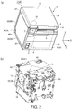
- FIG. 1 and FIG. 2 have external oblique views showing a roll paper printer according to this embodiment of the invention, and oblique views of the printer with the printer case removed, FIG. 1 (a) and FIG. 2 (a) being external oblique views, and FIG. 1 (b) and FIG. 2(b) showing the printer with the printer case removed.
- the invention is described below with reference to to three mutually perpendicular axes, the X-axis, Y-axis, and Z-axis.
- the arrows of the three XYZ axes in FIG. 1 and FIG. 2 point in the forward (positive) direction, and the direction opposite the direction in which the arrows point is the reverse (negative) direction.
- the roll paper printer 1 (printing device) is placed on the XY side, which is a horizontal surface.
- the roll paper printer 1 holds a paper roll 12 (see FIG. 3 , FIG. 4 ) of continuous recording paper 11 (see FIG. 3 , FIG. 4 ) wound into a roll, and prints to the recording paper 11 delivered from the paper roll 12.
- the roll paper printer 1 has a generally box-shaped printer case 2.
- the printer case 2 has a first side 21 (second surface) in which the recording paper exit 3 is formed.
- the first side 21 faces up (+Z-axis), and the recording paper exit 3 is located at the front edge (+Y-axis side) of the first side 21.
- This orientation in which the recording paper exit 3 is located at the top front edge (the front side when seen by the user) of the printer case 2 is referred to as the first orientation 1A of the roll paper printer 1.
- the printer case 2 has a second side 22 forming the bottom (-Z-axis side) in the first orientation 1A; a third side 23 (first surface) forming the front (+Y-axis side) in the first orientation 1A; a fourth side 24 forming the back (-Y-axis side) in the first orientation 1A; a fifth side 25 forming one side of the width (+X-axis side) in the first orientation 1A; and a sixth side 26 forming the other side of the width (-X-axis side) in the first orientation 1A.
- the first side 21 of the roll paper printer 1 faces the front (+Y-axis), and the recording paper exit 3 is at the front of the roll paper printer 1.
- This orientation is referred to as the second orientation 1B of the roll paper printer 1.
- the second side 22 is the back (-Y-axis side)
- the third side 23 is the top (+Z-axis side
- the fourth side 24 is the bottom (-Z-axis side).
- the fifth side 25 and sixth side 26 form one side (+X-axis side) of the width and the other side (-X-axis side) of the width.
- first side 21 (second surface) and the third side 23 (first surface) of the roll paper printer 1 are described below assuming the roll paper printer 1 is placed in the first orientation 1A shown in FIG. 1 (a) .
- a rectangular roll paper loading opening 4 for loading and removing the paper roll 12 is formed in the first side 21 of the printer case 2.
- the first side 21 also includes an access cover 5 that closes the roll paper loading opening 4, and a front end part 6 extending along the +Y-axis edge of the roll paper loading opening 4.
- the access cover 5 can pivot on the back end (-Y-axis end) thereof and move between the closed position 5A shown in FIG. 3 , and the open position 5B (see FIG. 4 ) standing vertically (+Z-axis).
- the access cover 5 When the access cover 5 is in the closed position 5A, the recording paper exit 3 is formed as a slot on the X-axis between the access cover 5 and the front end part 6.
- the access cover 5 also has an operating lever 7 located on one side (+X-axis side) of the width of the recording paper exit 3. A lock not shown is disengaged by pulling up on the operating lever 7. As a result, the access cover 5 can open upward.
- An operating unit 8 including a power switch is disposed at the back (-Y-axis side) corner of the access cover 5.
- the front end part 6 of the first side 21 has an incline that slopes diagonally up to the front (sloping in the +Y-axis and+Z-axis directions), and a display unit 9 is disposed to this incline.
- the display unit 9 displays information such as the operating state of the roll paper printer 1.
- the display unit 9 extends along the top edge part of the third side 23 where the third side 23 meets the first side 21.
- a NFC communication unit 10 (contactless communication unit) is disposed on the top edge part of the third side 23 on one side of the width (+X-axis side).
- the NFC communication unit 10 is a unit that reads information by contactless near-field communication from an NFC chip in a mobile terminal held by the user, for example, and can communicate by near-field communication conforming to the NFC(Near FieldCommunication) standard.
- the roll paper printer 1 can print based on information acquired by contactless near-field communication through the NFC communication unit 10.
- the recording paper exit 3, display unit 9, and NFC communication unit 10 are all concentrated at the corner where the device top (first side 21) and the device front (third side 23) meet.
- the recording paper exit 3, display unit 9, and NFC communication unit 10 are all concentrated at a position that is easily accessible at the front facing the user.
- the recording paper exit 3, display unit 9, and NFC communication unit 10 are all concentrated at the corner where the device top (third side 23) and the device front (first side 21) meet.
- the roll paper printer 1 can thus be set according to the location so that the recording paper 11 is discharged in either of two directions, up or to the front.
- the roll paper printer 1 is also configured so that convenience of operation is not impaired in either orientation.
- the NFC communication unit 10 is disposed with the round antenna surface facing the same direction as the third side 23.
- the area in the third side 23 where the NFC communication unit 10 is located is indicated by a dotted line, and a marking indicating where the NFC communication unit 10 for contactless near-field communication with an external terminal device is located is preferably presented on the third side 23.
- a marking indicating where the NFC communication unit 10 for contactless near-field communication with an external terminal device is located is preferably presented on the third side 23.
- an image or lettering indicating that the NFC communication unit 10 is located in that position is preferably displayed.
- that the external terminal device should be placed near this position for contactless communication is preferably indicated.
- Such indications may also be displayed on the first side 21.
- the access cover 5 opens to the top (+Z-axis side) by pivoting on the back end thereof at the top of the roll paper printer 1, thereby opening the roll paper loading opening 4 to the top.
- the paper roll 12 can therefore be replaced by removing the paper roll 12 from the top and dropping a paper roll 12 in from the top.
- the access cover 5 opens to the front (+Y-axis side) pivoting on the bottom end thereof at the front of the roll paper printer 1.
- the roll paper loading opening 4 therefore opens to the front.
- the paper roll 12 is replaced by removing the paper roll 12 from the front and loading a paper roll 12 from the front.
- the paper roll 12 can therefore be easily replaced in both orientations of the roll paper printer 1.
- FIG. 3 and FIG. 4 are vertical section views illustrating the internal configuration of the roll paper printer 1.
- FIG. 3 shows the access cover 5 closed
- FIG. 4 shows the access cover 5 open.
- FIG. 3 and FIG. 4 also show the roll paper printer 1 in the first orientation 1A.
- the internal configuration of the roll paper printer 1 is described below when in the first orientation 1A based on FIG. 3 and FIG. 4 .
- a cutter mechanism 30 for cutting the recording paper 11 is disposed inside the printer case 2 near the recording paper exit 3. Below the cutter mechanism 30 are a platen roller 31 (conveyance roller) and printhead 32.
- the platen roller 31 is mounted on a platen support frame 33 that supports the access cover 5 from the back side (-Z-axis side) .
- the access cover 5, cutter mechanism 30, and platen roller 31 mechanisms embody an access cover unit 34 that opens and closes in unison with the platen support frame 33. As shown in FIG. 3 , when the access cover unit 34 is in the closed position 34A, the access cover 5 is in the closed position 5A. As shown in FIG. 4 , when the access cover unit 34 is in the open position 34B, the access cover 5 is in the open position 5B.
- a roll paper compartment 40 is located below the access cover unit 34.
- the roll paper compartment 40 has a roll paper holder 41 that holds a paper roll 12.
- the middle of the roll paper holder 41 on the Y-axis is recessed to the -Z-axis side, and faces the roll paper loading opening 4 formed in the first side 21.
- the access cover unit 34 opens as shown in FIG. 4 , the paper roll 12 can be removed and loaded to the roll paper holder 41 from the roll paper loading opening 4.
- the loaded paper roll 12 is held resting movably on the bottom of the roll paper holder 41.
- the front end (+Y-axis end) of the roll paper holder 41 rises vertically (+Z-axis), and a delivery roller 35, which is a follower roller, is located near the top.
- the recording paper 11 delivered from the paper roll 12 is set passing over the delivery roller 35, along a paper guide 36 located at the bottom end of the platen support frame 33, and between the platen roller 31 and printhead 32.
- the recording paper 11 is conveyed by the conveyance force of the platen roller 31, passes between the fixed knife and movable knife of the cutter mechanism 30, and is discharged from the recording paper exit 3 to the top of the printer case 2.
- a paper detection lever 37 is disposed to this curved path.
- the paper detection lever 37 contacts the bottom (the inside of the curve) of recording paper 11 conveyed up through the curve, and detects the recording paper 11.
- the roll paper printer 1 has a circuit board 60 disposed to the back side (inside) of the third side 23 of the printer case 2. Various control elements are mounted on this circuit board 60.
- a controller 61 that controls parts of the roll paper printer 1 is embodied by the control elements and circuits on the circuit board 60.
- One end of the circuit board 60 extends to near the corner between the third side 23 and second side 22.
- the other end of the circuit board 60 extends to a position removed a specific distance from the corner between the third side 23 and first side 21, and the NFC communication unit 10 is disposed between this other end of the circuit board 60 and the corner between the third side 23 and first side 21.
- the controller 61 can acquire information by contactless near-field communication from an external terminal device through the NFC communication unit 10.
- the circuit board 60 is covered by a sheet metal panel 62 between the circuit board 60 and the third side 23 of the printer case 2.
- the circuit board 60 is also affixed to a sheet metal frame 63 disposed to the opposite side as the sheet metal panel 62.
- the sheet metal panel 62 and frame 63 allow static electricity to drain when a static charge is produced near the circuit board 60. Failures and faults in the control elements and circuits on the circuit board 60 caused by static electricity can therefore be avoided.
- the sheet metal panel 62 and frame 63 are preferably located so there is no interference with contactless communication by the NFC communication unit 10. More specifically, so that the magnetic field produced by the NFC communication unit 10 does not produce induction current in the sheet metal panel 62 and frame 63 that will then cancel and weaken the magnetic field produced by the NFC communication unit 10, the sheet metal panel 62 and frame 63 are preferably disposed at positions where there is no intersection with the magnetic field produced by the NFC communication unit 10. More specifically, the sheet metal panel 62 and frame 63 are preferably located at least a specific distance away from the NFC communication unit 10.
- the circuit board 60 is also covered by a water resistant sheet 64 (water resistant member) on the same side as the frame 63.
- the water resistant sheet 64 is draped over the the NFC communication unit 10 side edge of the circuit board 60 with one side side of the water resistant sheet 64 completely covering the frame 63 side surface of the circuit board 60, and the other end side covering the circuit board 60 so that part of the sheet metal panel 62 side of the circuit board 60 is covered.
- the cutter mechanism 30 is on the same side of the circuit board 60 as the NFC communication unit 10. The cutter mechanism 30 is located on the back side of the recording paper exit 3 formed in the first side 21.
- FIG. 5 is an oblique view of the internal configuration through a plane parallel to the first side 21 with the printer case 2 removed, and shows the internal configuration in the same first orientation 1A as in FIG. 1 , FIG. 3 , and FIG. 4 .
- a sheet metal frame is disposed along the inside surfaces of the third side 23, fourth side 24, and sixth side 26 of the printer case 2, and the roll paper holder 41 is disposed in the space surrounded by this frame.
- the roll paper holder 41 is disposed so that the direction from the third side 23 to the fourth side 24 (the Y-axis in FIG. 5 ) is the direction in which the paper roll 12 turns in the roll paper holder 41.
- the roll paper printer 1 is placed so that the direction perpendicular to the direction of rotation R of the paper roll 12 (the X-axis in FIG. 5 ) is the width of the roll paper printer 1 as seen from the user.
- the roll paper holder 41 is disposed on one side (-X-axis side, the side of the sixth side 26) of the width (the direction perpendicular to the direction of rotation R: the X-axis) inside the printer case 2. Between the roll paper holder 41 and the fifth side 25 is a drive mechanism space 65 where the drive mechanisms of the roll paper printer 1 are concentrated.
- the drive mechanism space 65 is the space between the roll paper holder 41 and fifth side 25 extending from the circuit board 60 on the third side 23 side to the back side of the fourth side 24.
- the roll paper printer 1 has a conveyance mechanism 70 that conveys the recording paper 11, and a conveyance motor 71 that drives the conveyance mechanism 70.
- the conveyance mechanism 70 includes the platen roller 31 that conveys the recording paper 11, and a roller drive mechanism 72 such as a gear train that transfers drive power from the conveyance motor 71 to the platen roller 31.
- the conveyance motor 71 and part of the roller drive mechanism 72 are located inside the drive mechanism space 65 on the circuit board 60 side.
- the cutter mechanism 30 of the roll paper printer 1 includes a movable knife and a fixed knife disposed to the back side of the recording paper exit 3, a cutter motor 73 that drives the movable knife, and a movable knife drive mechanism 74 such as a gear train and cam that transfer drive power from the cutter motor 73 to the movable knife.
- the cutter motor 73 and part of the movable knife drive mechanism 74 are located inside the drive mechanism space 65 in the area near the fourth side 24.
- FIG. 6 (a) is an oblique view of the roll paper printer 1 as seen from the bottom and back sides
- FIG. 6 (b) is an oblique view with the parts forming the bottom and back of the printer case 2 removed.
- a first cover 80, and a first opening 81 that the first cover 80 covers are formed on the second side 22 of the printer case 2.
- a second cover 82, and a second opening 83 that the second cover 82 covers, are formed on the fourth side 24 of the printer case 2.
- the second side 22 and the fourth side 24 are connected, and the first opening 81 and the second opening 83 are connected.
- the roll paper holder 41 described above, and a support frame 66 that supports the roll paper holder 41 and drive mechanism, are disposed on the inside side of the second side 22.
- the support frame 66 is located at a position removed a specific distance toward the first side 21 from the second side 22.
- a connector housing 67 is formed between the first cover 80 and the support frame 66.
- the connector housing 67 is a space between the first cover 80 and the support frame 66.
- a device-side connector mount 68 is disposed at the corner between the second side 22 and third side 23.
- the device-side connector mount 68 has a connector mounting surface 69 facing the connector housing 67.
- the connector mounting surface 69 is a surface facing the fourth side 24, and multiple connectors 90 (device-side connectors) for connecting cables are exposed at this surface.
- connector 90 terminals for a power connection, a USB connection, and a LAN connection are exposed.
- These connectors 90 can connect to external connectors 91 attached to the cables that are connected to the external devices and power unit.
- the second cover 82 has a rectangular flat panel 82a, a first edge portion 82b that rises from the edge of the flat panel 82a on the side connecting to the first cover 80, and a second edge portion 82c and a third edge portion 82d that rise from the two edges contiguous to the edge where the first edge portion 82b is formed.
- a notch 84 of a specific width is formed in the middle of the first edge portion 82b.
- Notches 85A and 85B contiguous to the first edge portion 82b are respectively formed in the second edge portion 82c and third edge portion 82d.
- the notch 85A in the second cover 82 connects to a notch 86A formed in the corner of the fifth side 25, forming a wiring hole 87A.
- the notch 85B in the second cover 82 connects to a notch 86B formed in the corner of the sixth side 26, forming another wiring hole 87B.
- Another wiring hole 88 is formed between the middle notch 84 in the first edge portion 82b and the first cover 80.
- Wiring holes 87A, 87B, and 88 are holes that communicate with the connector housing 67. Therefore, the cables of the external connectors 91 connected to the connectors 90 of the connector mounting surface 69 inside the connector housing 67 can pass through the wiring holes 87A, 87B, and 88 to the outside.
- a roll paper printer 1 has a NFC communication unit 10 for communicating by contactless near-field communication, and can be placed in a first orientation 1A in which the third side 23 (first surface) to which the NFC communication unit 10 is disposed is at the front, or a second orientation 1B in which the third side 23 is at the top. Therefore, whether in the first orientation 1A or the second orientation 1B, the NFC communication unit 10 is located at a position easily accessible to the user. There is no need to provide a second NFC communication unit 10, or a means of changing the location of the NFC communication unit 10, in order to assure ease of use. This is beneficial for achieving a small size.
- the NFC communication unit 10 is disposed at a corner between the third side 23 (first surface) and first side 21 (second surface), in the location of the NFC communication unit 10 does not change substantially when the printer orientation is changed. Ease of use therefore does not change. Furthermore, locating the NFC communication unit 10 at the corner of the top and the front is convenient for near-field communication with a terminal held by the user.
- the circuit board 60 comprising the controller 61 that controls parts of the roll paper printer 1 is disposed in the space between the printing mechanism including the printhead 32 and roll paper holder 41, and the third side 23 of the printer case 2. Space efficiency is therefore good and beneficial for a small device configuration. Furthermore, because the NFC communication unit 10 is near the circuit board 60, connecting the NFC communication unit 10 and circuit board 60 is simple.
- the circuit board 60 is also covered by a water resistant sheet 64 from the recording paper exit 3 side in this embodiment, and a sheet metal panel 62 is disposed along the circuit board 60. Failure and faults in the control elements and circuits on the circuit board 60 due to contact with liquid entering from the recording paper exit 3 can therefore be prevented. Failure and faults in the control elements and circuits on the circuit board 60 due to static electricity can also be avoided.
- the conveyance motor 71 and roller drive mechanism 72 of the conveyance mechanism 70, and the cutter motor 73 and movable knife drive mechanism 74 of the cutter mechanism 30, are also concentrated together in the same direction as the direction of rotation R of the paper roll 12 relative to the roll paper holder 41. Therefore, large drive components such as the conveyance motor 71 and cutter motor 73 can be concentrated in the space left after disposing the roll paper holder 41 in the printer case 2. An arrangement that uses space efficiently is therefore achieved, and the printing mechanism unit can be configured compactly. This is also beneficial for a small device size. More particularly, because the roll paper holder 41 is long in the direction of rotation R of the paper roll 12, a configuration with good space efficiency can be achieved when the roll paper printer 1 is basically shaped like a cube.
- a connector housing 67 for holding the external connectors 91 is formed inside the second side 22 of the printer case 2, and a device-side connector mount 68 is disposed to the connector housing 67.
- all external connectors 91 connected to the device-side connectors 90 can be housed in the connector housing 67.
- Space for placing a connection unit for the connectors is not needed outside the printer case 2, and the appearance is better when installed. Problems resulting from accidentally touching connections between the external connectors 91 and device-side connectors 90 can also be avoided.
- the invention is useful in a printing device that can be placed and used in multiple orientations, such as vertically and horizontally, and can be used in a printing device that can be used in different orientations without reducing user access to the operating unit.
Landscapes
- Engineering & Computer Science (AREA)
- General Engineering & Computer Science (AREA)
- Theoretical Computer Science (AREA)
- Physics & Mathematics (AREA)
- General Physics & Mathematics (AREA)
- Human Computer Interaction (AREA)
- Computer Networks & Wireless Communication (AREA)
- Accessory Devices And Overall Control Thereof (AREA)
- Handling Of Sheets (AREA)
- Handling Of Continuous Sheets Of Paper (AREA)
Abstract
Description
- The present invention relates to a printing device that can be used in multiple orientations, including vertically and horizontally.
- Roll paper printers and other types of printing devices that hold a roll of continuous recording paper in a roll paper holder, and print to the recording paper pulled from the paper roll are known from the literature. Due to limited space where the printing device is used, for example, some printing devices of this type are configured so that they can be used in either of two orientations, vertically or horizontally. For example, the roll paper printer (printing device) described in
PTL 1 can be placed in a horizontal orientation on a horizontal surface, or mounted vertically on a wall. When mounted on a wall, the surface that is the back when placed horizontally is on the bottom facing down.PTL 2 describes a facsimile machine (printing device) that can used either vertically or horizontally. - The locations of the parts of the printing device and the operating direction relative to the user change depending on the orientation (placement) of a printing device that can be used vertically or horizontally. The locations of the parts of the printing device and the operating direction also change relative to the vertical axis. This can adversely affect ease of use. Where the paper roll is held inside the printing device and the conveyance path may also change, resulting in problems with supplying the recording paper and detecting the recording paper. To accommodate the location where the paper roll is held changing, the roll paper printer described in
PTL 1 has recesses for holding the roll paper at two locations in the roll paper holder. The printer also has two locations for installing a detector for detecting the roll paper, and the location of the detector can be changed according to the orientation of the printer. Because the orientation of the display unit reverses relative to the user when the orientation of the facsimile machine changes, the facsimile machine described inPTL 2 enables control reversing the orientation of the content displayed on the display unit, or reversing the orientation in which the display unit is installed. -
- [PTL 1]
JP-A-H9-295436 - [PTL 2]
JP-A-H6-233018 - Providing a contactless communication device for contactlessly reading information fromamobile terminal held by the user, for example, as a means of inputting information to the printing device is also desirable. However, when the printing device is equipped with such a contactless communication device, the location of the communication unit may become farther from the user when the orientation of the printer changes, and ease of use may deteriorate. There are also configurations other than the contactless communication device that become more difficult to use when the printer orientation changes, and similar problems thus occur with the locations of the paper exit from which the recording paper is discharged, the display unit, and the access cover that opens and closes the opening for loading the roll paper.
- To resolve problems resulting from changing the orientation,
PTL - With consideration for the foregoing problem, an objective of the present invention is to provide a printing device that can maintain ease of use even when the installed orientation changes and is beneficial for reducing device size.
- To solve the foregoing problem, the invention is characterized by: a printhead that prints on recording paper; a contactless communication unit that communicates by contactless near-field communication; and a case that houses the printhead and the contactless communication unit; the case having a first surface where the contactless communication unit is disposed, and a second surface that connects to the first surface and has a recording paper exit from which the recording paper is discharged; the printing device being usable in a first orientation in which the second surface is the top, and a second orientation in which the second surface is the front.
- The invention thus has a contactless communication unit for contactless near-field communication, and can be placed in a first orientation in which the second surface to which the contactless communication unit is disposed is at the top, or a second orientation in which the second surface is at the front. Therefore, whether placed in the first orientation or the second orientation, the contactless communication unit can be placed at a position easily accessible to the user. There is also no need to provide a second contactless communication unit, or a means of changing the location of the contactless communication unit, in order to assure ease of use. This is beneficial for achieving a small size.
- In the invention, the contact less communication unit is preferably disposed at a corner where the first surface and the second surface meet. Thus comprised, because the contactless communication unit is disposed to the corner where the front and top connect, there is substantially no change in the location of the contactless communication unit even if the orientation is changed. Ease of use therefore does not change. Furthermore, placing the contactless communication unit at the corner of the top and the front is convenient for near-field communication with a terminal held by the user.
- In the invention, an indication of the place where the contactless communication unit is located is preferably provided on the first surface or the second surface. Thus comprised, the user can know by looking where to hold the external terminal device near. User convenience is therefore excellent.
- The invention preferably also has a circuit board configuring a control unit that controls the print head based on information acquired by the contactless communication unit, and the circuit board is disposed along the first surface. Thus comprised, the space between the case and the print mechanism unit including the print mechanism, conveyance mechanism, and roll paper compartment can be used to locate the circuit board. This uses space efficiently and helps making the printing device small. Connecting the contactless communication unit and circuit board is also easy because the contactless communication unit and circuit board are close together.
- The invention preferably also has a water resistant member covering the circuit board on the recording paper exit side. Thus comprised, problems resulting from the liquid contacting the circuit board can be avoided even if water or other liquid enters from the recording paper exit.
- Further preferably in this configuration, a sheet metal member is disposed along the circuit board, and the sheet metal member is separated at least a specific distance from the contactless communication unit. Thus comprised, if static electricity is produced near the circuit board, the static electricity can be drained by the sheet metal member. Static electricity can also be prevented from creating problems in control elements on the circuit board. Furthermore, by separating the sheet metal member from the contactless communication unit, interference by the sheet metal member with stable near-field communication when an external terminal device is held near the contactless communication unit can also be avoided.
- Further preferably, the invention has either or both a display unit disposed at a corner where the first surface and the second surface connect; and an access cover disposed to the first surface or the second surface. Thus comprised, the display unit and access cover, and not only the contactless communication unit, can be located at a position easily accessible to the user regardless of the orientation of the printing device.
- Preferably, the invention also has a conveyance mechanism that conveys the recording paper, and a conveyance motor that drives the conveyance mechanism; a cutter mechanism that cuts the recording paper, and a cutter motor that drives the cutter mechanism; and a roll paper holder in which a paper roll of the recording paper wound into a roll is held; and the conveyance motor and the cutter motor are disposed on the same side of the roll paper holder. For example, when the direction in which the paper roll in the roll paper holder rolls is the direction of rotation, the conveyance motor and the cutter motor are preferably located on the same side of the roll paper holder in the direction perpendicular to the direction of rotation. Thus comprised, drive units such as the conveyance motor and cutter motor can be concentrated in the space left after disposing the roll paper holder inside the printer case. A space-efficient arrangement therefore be achieved, and the printing mechanism unit can be compactly configured. This also helps achieve a small device. Furthermore, if drive units such as the conveyance motor and cutter motor are concentrated in the space that is long in the direction of rotation created on the side of the width of the roll paper holder, an arrangement that uses space efficiently when the printer is shaped like a cube can be achieved.
- The invention preferably also has a device-side connector to which an external connector connected to an external cable can connect; the case has a connector housing that can house the external connector; and the device-side connector is disposed facing the connector housing. This configuration can house all external connectors connected to the device-side connectors inside the case. Space for placing a connection unit for the connectors is not needed outside the case, and the appearance is better when installed. Problems resulting from accidentally touching the connections between the external connectors and device-side connectors can also be avoided.
-
-
FIG. 1 is an external oblique view of a roll paper printer according to the invention, and an oblique view of the roll paper printer with the printer case removed (in a first orientation). -
FIG. 2 is an external oblique view of a roll paper printer according to the invention, and an oblique view of the roll paper printer with the printer case removed (in a second orientation). -
FIG. 3 is a vertical section view showing the internal configuration of the roll paper printer (with the access cover closed). -
FIG. 4 is a vertical section view showing the internal configuration of the roll paper printer (with the access cover open). -
FIG. 5 is an oblique section view through a plane parallel to a first side showing the internal configuration with the printer case removed. -
FIG. 6 is an oblique view of the roll paper printer showing the bottom and back sides, and an oblique view with the parts of the printer case forming the bottom and back sides removed. - A preferred embodiment of a roll paper printer according to the invention is described below with reference to the accompanying figures.
-
FIG. 1 andFIG. 2 have external oblique views showing a roll paper printer according to this embodiment of the invention, and oblique views of the printer with the printer case removed,FIG. 1 (a) andFIG. 2 (a) being external oblique views, andFIG. 1 (b) andFIG. 2(b) showing the printer with the printer case removed. The invention is described below with reference to to three mutually perpendicular axes, the X-axis, Y-axis, and Z-axis. The arrows of the three XYZ axes inFIG. 1 andFIG. 2 point in the forward (positive) direction, and the direction opposite the direction in which the arrows point is the reverse (negative) direction. When in use, the roll paper printer 1 (printing device) is placed on the XY side, which is a horizontal surface. Theroll paper printer 1 holds a paper roll 12 (seeFIG. 3 ,FIG. 4 ) of continuous recording paper 11 (seeFIG. 3 ,FIG. 4 ) wound into a roll, and prints to therecording paper 11 delivered from thepaper roll 12. - The
roll paper printer 1 has a generally box-shapedprinter case 2. Theprinter case 2 has a first side 21 (second surface) in which therecording paper exit 3 is formed. In the orientation shown inFIG. 1 (a) , thefirst side 21 faces up (+Z-axis), and therecording paper exit 3 is located at the front edge (+Y-axis side) of thefirst side 21. This orientation in which therecording paper exit 3 is located at the top front edge (the front side when seen by the user) of theprinter case 2 is referred to as thefirst orientation 1A of theroll paper printer 1. Theprinter case 2 has asecond side 22 forming the bottom (-Z-axis side) in thefirst orientation 1A; a third side 23 (first surface) forming the front (+Y-axis side) in thefirst orientation 1A; afourth side 24 forming the back (-Y-axis side) in thefirst orientation 1A; afifth side 25 forming one side of the width (+X-axis side) in thefirst orientation 1A; and asixth side 26 forming the other side of the width (-X-axis side) in thefirst orientation 1A. - When placed as shown in
FIG. 2 (a) , thefirst side 21 of theroll paper printer 1 faces the front (+Y-axis), and therecording paper exit 3 is at the front of theroll paper printer 1. This orientation is referred to as thesecond orientation 1B of theroll paper printer 1. In thesecond orientation 1B, thesecond side 22 is the back (-Y-axis side), thethird side 23 is the top (+Z-axis side), and thefourth side 24 is the bottom (-Z-axis side). As in thefirst orientation 1A, thefifth side 25 andsixth side 26 form one side (+X-axis side) of the width and the other side (-X-axis side) of the width. - The configuration of the first side 21 (second surface) and the third side 23 (first surface) of the
roll paper printer 1 are described below assuming theroll paper printer 1 is placed in thefirst orientation 1A shown inFIG. 1 (a) . - A rectangular roll
paper loading opening 4 for loading and removing thepaper roll 12 is formed in thefirst side 21 of theprinter case 2. Thefirst side 21 also includes anaccess cover 5 that closes the rollpaper loading opening 4, and afront end part 6 extending along the +Y-axis edge of the rollpaper loading opening 4. Theaccess cover 5 can pivot on the back end (-Y-axis end) thereof and move between theclosed position 5A shown inFIG. 3 , and theopen position 5B (seeFIG. 4 ) standing vertically (+Z-axis). When theaccess cover 5 is in theclosed position 5A, therecording paper exit 3 is formed as a slot on the X-axis between theaccess cover 5 and thefront end part 6. Theaccess cover 5 also has an operatinglever 7 located on one side (+X-axis side) of the width of therecording paper exit 3. A lock not shown is disengaged by pulling up on the operatinglever 7. As a result, theaccess cover 5 can open upward. - An
operating unit 8 including a power switch is disposed at the back (-Y-axis side) corner of theaccess cover 5. Thefront end part 6 of thefirst side 21 has an incline that slopes diagonally up to the front (sloping in the +Y-axis and+Z-axis directions), and adisplay unit 9 is disposed to this incline. Thedisplay unit 9 displays information such as the operating state of theroll paper printer 1. Thedisplay unit 9 extends along the top edge part of thethird side 23 where thethird side 23 meets thefirst side 21. A NFC communication unit 10 (contactless communication unit) is disposed on the top edge part of thethird side 23 on one side of the width (+X-axis side). TheNFC communication unit 10 is a unit that reads information by contactless near-field communication from an NFC chip in a mobile terminal held by the user, for example, and can communicate by near-field communication conforming to the NFC(Near FieldCommunication) standard. Theroll paper printer 1 can print based on information acquired by contactless near-field communication through theNFC communication unit 10. - When the
roll paper printer 1 is placed in thefirst orientation 1A shown inFIG. 1 (a) , therecording paper exit 3,display unit 9, andNFC communication unit 10 are all concentrated at the corner where the device top (first side 21) and the device front (third side 23) meet. In other words, therecording paper exit 3,display unit 9, andNFC communication unit 10 are all concentrated at a position that is easily accessible at the front facing the user. When placed in thesecond orientation 1B shown inFIG. 2 (a) , Therecording paper exit 3,display unit 9, andNFC communication unit 10 are all concentrated at the corner where the device top (third side 23) and the device front (first side 21) meet. Thefirst orientation 1A shown inFIG. 1 (a) is the orientation in which thefirst side 21 of therecording paper exit 3 is at the device top, and the printedrecording paper 11 can be discharged up (+Z-axis) from the device top. Thesecond orientation 1B shown inFIG. 2 (a) is the orientation in which thefirst side 21 of therecording paper exit 3 is at the device front, and the printedrecording paper 11 can be discharged to the front (+Y-axis) from the device front. Theroll paper printer 1 can thus be set according to the location so that therecording paper 11 is discharged in either of two directions, up or to the front. Theroll paper printer 1 is also configured so that convenience of operation is not impaired in either orientation. - 1 As shown in
FIG. 1 (b) andFIG. 2 (b) , theNFC communication unit 10 is disposed with the round antenna surface facing the same direction as thethird side 23. InFIG. 1 (a) andFIG. 2 (a) , the area in thethird side 23 where theNFC communication unit 10 is located is indicated by a dotted line, and a marking indicating where theNFC communication unit 10 for contactless near-field communication with an external terminal device is located is preferably presented on thethird side 23. For example, an image or lettering indicating that theNFC communication unit 10 is located in that position is preferably displayed. Alternatively, that the external terminal device should be placed near this position for contactless communication is preferably indicated. Such indications may also be displayed on thefirst side 21. - In the
first orientation 1A shown inFIG. 1 (a) , theaccess cover 5 opens to the top (+Z-axis side) by pivoting on the back end thereof at the top of theroll paper printer 1, thereby opening the rollpaper loading opening 4 to the top. Thepaper roll 12 can therefore be replaced by removing thepaper roll 12 from the top and dropping apaper roll 12 in from the top. In thesecond orientation 1B shown inFIG. 2 (a) , theaccess cover 5 opens to the front (+Y-axis side) pivoting on the bottom end thereof at the front of theroll paper printer 1. The rollpaper loading opening 4 therefore opens to the front. Thepaper roll 12 is replaced by removing thepaper roll 12 from the front and loading apaper roll 12 from the front. Thepaper roll 12 can therefore be easily replaced in both orientations of theroll paper printer 1. -
FIG. 3 andFIG. 4 are vertical section views illustrating the internal configuration of theroll paper printer 1.FIG. 3 shows theaccess cover 5 closed, andFIG. 4 shows theaccess cover 5 open.FIG. 3 andFIG. 4 also show theroll paper printer 1 in thefirst orientation 1A. The internal configuration of theroll paper printer 1 is described below when in thefirst orientation 1A based onFIG. 3 andFIG. 4 . Acutter mechanism 30 for cutting therecording paper 11 is disposed inside theprinter case 2 near therecording paper exit 3. Below thecutter mechanism 30 are a platen roller 31 (conveyance roller) andprinthead 32. Theplaten roller 31 is mounted on aplaten support frame 33 that supports theaccess cover 5 from the back side (-Z-axis side) . Theaccess cover 5,cutter mechanism 30, andplaten roller 31 mechanisms embody anaccess cover unit 34 that opens and closes in unison with theplaten support frame 33. As shown inFIG. 3 , when theaccess cover unit 34 is in theclosed position 34A, theaccess cover 5 is in theclosed position 5A. As shown inFIG. 4 , when theaccess cover unit 34 is in theopen position 34B, theaccess cover 5 is in theopen position 5B. - A
roll paper compartment 40 is located below theaccess cover unit 34. Theroll paper compartment 40 has aroll paper holder 41 that holds apaper roll 12. The middle of theroll paper holder 41 on the Y-axis is recessed to the -Z-axis side, and faces the rollpaper loading opening 4 formed in thefirst side 21. When theaccess cover unit 34 opens as shown inFIG. 4 , thepaper roll 12 can be removed and loaded to theroll paper holder 41 from the rollpaper loading opening 4. The loadedpaper roll 12 is held resting movably on the bottom of theroll paper holder 41. - As shown in
FIG. 3 andFIG. 4 , when in thefirst orientation 1A, the front end (+Y-axis end) of theroll paper holder 41 rises vertically (+Z-axis), and adelivery roller 35, which is a follower roller, is located near the top. Therecording paper 11 delivered from thepaper roll 12 is set passing over thedelivery roller 35, along apaper guide 36 located at the bottom end of theplaten support frame 33, and between theplaten roller 31 andprinthead 32. Therecording paper 11 is conveyed by the conveyance force of theplaten roller 31, passes between the fixed knife and movable knife of thecutter mechanism 30, and is discharged from therecording paper exit 3 to the top of theprinter case 2. Because thepaper guide 36 protrudes at a downward angle, the conveyance path passing thedelivery roller 35 andpaper guide 36 curves in an upwardly convex shape. Apaper detection lever 37 is disposed to this curved path. Thepaper detection lever 37 contacts the bottom (the inside of the curve) ofrecording paper 11 conveyed up through the curve, and detects therecording paper 11. - The
roll paper printer 1 has acircuit board 60 disposed to the back side (inside) of thethird side 23 of theprinter case 2. Various control elements are mounted on thiscircuit board 60. Acontroller 61 that controls parts of theroll paper printer 1 is embodied by the control elements and circuits on thecircuit board 60. One end of thecircuit board 60 extends to near the corner between thethird side 23 andsecond side 22. The other end of thecircuit board 60 extends to a position removed a specific distance from the corner between thethird side 23 andfirst side 21, and theNFC communication unit 10 is disposed between this other end of thecircuit board 60 and the corner between thethird side 23 andfirst side 21. Thecontroller 61 can acquire information by contactless near-field communication from an external terminal device through theNFC communication unit 10. - The
circuit board 60 is covered by asheet metal panel 62 between thecircuit board 60 and thethird side 23 of theprinter case 2. Thecircuit board 60 is also affixed to asheet metal frame 63 disposed to the opposite side as thesheet metal panel 62. Thesheet metal panel 62 andframe 63 allow static electricity to drain when a static charge is produced near thecircuit board 60. Failures and faults in the control elements and circuits on thecircuit board 60 caused by static electricity can therefore be avoided. - The
sheet metal panel 62 andframe 63 are preferably located so there is no interference with contactless communication by theNFC communication unit 10. More specifically, so that the magnetic field produced by theNFC communication unit 10 does not produce induction current in thesheet metal panel 62 andframe 63 that will then cancel and weaken the magnetic field produced by theNFC communication unit 10, thesheet metal panel 62 andframe 63 are preferably disposed at positions where there is no intersection with the magnetic field produced by theNFC communication unit 10. More specifically, thesheet metal panel 62 andframe 63 are preferably located at least a specific distance away from theNFC communication unit 10. - As shown in
FIG. 3 andFIG. 4 , thecircuit board 60 is also covered by a water resistant sheet 64 (water resistant member) on the same side as theframe 63. The waterresistant sheet 64 is draped over the theNFC communication unit 10 side edge of thecircuit board 60 with one side side of the waterresistant sheet 64 completely covering theframe 63 side surface of thecircuit board 60, and the other end side covering thecircuit board 60 so that part of thesheet metal panel 62 side of thecircuit board 60 is covered. Thecutter mechanism 30 is on the same side of thecircuit board 60 as theNFC communication unit 10. Thecutter mechanism 30 is located on the back side of therecording paper exit 3 formed in thefirst side 21. Therefore, if water or other liquid enters from therecording paper exit 3 and the liquid passes between the fixed knife and movable knife of thecutter mechanism 30 and reaches thecircuit board 60 side, the liquid can be prevented from contacting the control elements and circuits on thecircuit board 60. Failure and faults in the control elements and circuits on thecircuit board 60 due to contact with liquid can therefore be prevented. -
FIG. 5 is an oblique view of the internal configuration through a plane parallel to thefirst side 21 with theprinter case 2 removed, and shows the internal configuration in the samefirst orientation 1A as inFIG. 1 ,FIG. 3 , andFIG. 4 . As shown in the figure, a sheet metal frame is disposed along the inside surfaces of thethird side 23,fourth side 24, andsixth side 26 of theprinter case 2, and theroll paper holder 41 is disposed in the space surrounded by this frame. Theroll paper holder 41 is disposed so that the direction from thethird side 23 to the fourth side 24 (the Y-axis inFIG. 5 ) is the direction in which thepaper roll 12 turns in theroll paper holder 41. Theroll paper printer 1 is placed so that the direction perpendicular to the direction of rotation R of the paper roll 12 (the X-axis inFIG. 5 ) is the width of theroll paper printer 1 as seen from the user. - The
roll paper holder 41 is disposed on one side (-X-axis side, the side of the sixth side 26) of the width (the direction perpendicular to the direction of rotation R: the X-axis) inside theprinter case 2. Between theroll paper holder 41 and thefifth side 25 is adrive mechanism space 65 where the drive mechanisms of theroll paper printer 1 are concentrated. Thedrive mechanism space 65 is the space between theroll paper holder 41 andfifth side 25 extending from thecircuit board 60 on thethird side 23 side to the back side of thefourth side 24. - The
roll paper printer 1 has aconveyance mechanism 70 that conveys therecording paper 11, and aconveyance motor 71 that drives theconveyance mechanism 70. Theconveyance mechanism 70 includes theplaten roller 31 that conveys therecording paper 11, and aroller drive mechanism 72 such as a gear train that transfers drive power from theconveyance motor 71 to theplaten roller 31. Theconveyance motor 71 and part of theroller drive mechanism 72 are located inside thedrive mechanism space 65 on thecircuit board 60 side. Thecutter mechanism 30 of theroll paper printer 1 includes a movable knife and a fixed knife disposed to the back side of therecording paper exit 3, acutter motor 73 that drives the movable knife, and a movableknife drive mechanism 74 such as a gear train and cam that transfer drive power from thecutter motor 73 to the movable knife. Thecutter motor 73 and part of the movableknife drive mechanism 74 are located inside thedrive mechanism space 65 in the area near thefourth side 24. -
FIG. 6 (a) is an oblique view of theroll paper printer 1 as seen from the bottom and back sides, andFIG. 6 (b) is an oblique view with the parts forming the bottom and back of theprinter case 2 removed. As shown in the figure, afirst cover 80, and afirst opening 81 that thefirst cover 80 covers, are formed on thesecond side 22 of theprinter case 2. Asecond cover 82, and asecond opening 83 that thesecond cover 82 covers, are formed on thefourth side 24 of theprinter case 2. Thesecond side 22 and thefourth side 24 are connected, and thefirst opening 81 and thesecond opening 83 are connected. - As shown in
FIG. 3 andFIG. 4 , theroll paper holder 41 described above, and asupport frame 66 that supports theroll paper holder 41 and drive mechanism, are disposed on the inside side of thesecond side 22. Thesupport frame 66 is located at a position removed a specific distance toward thefirst side 21 from thesecond side 22. When thefirst cover 80 is installed covering thefirst opening 81, aconnector housing 67 is formed between thefirst cover 80 and thesupport frame 66. Theconnector housing 67 is a space between thefirst cover 80 and thesupport frame 66. - A device-
side connector mount 68 is disposed at the corner between thesecond side 22 andthird side 23. The device-side connector mount 68 has aconnector mounting surface 69 facing theconnector housing 67. Theconnector mounting surface 69 is a surface facing thefourth side 24, and multiple connectors 90 (device-side connectors) for connecting cables are exposed at this surface. In this example,connector 90 terminals for a power connection, a USB connection, and a LAN connection are exposed. Theseconnectors 90 can connect toexternal connectors 91 attached to the cables that are connected to the external devices and power unit. - The
second cover 82 has a rectangularflat panel 82a, afirst edge portion 82b that rises from the edge of theflat panel 82a on the side connecting to thefirst cover 80, and asecond edge portion 82c and athird edge portion 82d that rise from the two edges contiguous to the edge where thefirst edge portion 82b is formed. Anotch 84 of a specific width is formed in the middle of thefirst edge portion 82b.Notches first edge portion 82b are respectively formed in thesecond edge portion 82c andthird edge portion 82d. When thefirst cover 80 is attached to thefirst opening 81, and thesecond cover 82 is attached to thesecond opening 83, thenotch 85A in thesecond cover 82 connects to anotch 86A formed in the corner of thefifth side 25, forming awiring hole 87A. Likewise, thenotch 85B in thesecond cover 82 connects to anotch 86B formed in the corner of thesixth side 26, forming anotherwiring hole 87B. Anotherwiring hole 88 is formed between themiddle notch 84 in thefirst edge portion 82b and thefirst cover 80. Wiring holes 87A, 87B, and 88 are holes that communicate with theconnector housing 67. Therefore, the cables of theexternal connectors 91 connected to theconnectors 90 of theconnector mounting surface 69 inside theconnector housing 67 can pass through the wiring holes 87A, 87B, and 88 to the outside. - As described above, a
roll paper printer 1 according to this embodiment has aNFC communication unit 10 for communicating by contactless near-field communication, and can be placed in afirst orientation 1A in which the third side 23 (first surface) to which theNFC communication unit 10 is disposed is at the front, or asecond orientation 1B in which thethird side 23 is at the top. Therefore, whether in thefirst orientation 1A or thesecond orientation 1B, theNFC communication unit 10 is located at a position easily accessible to the user. There is no need to provide a secondNFC communication unit 10, or a means of changing the location of theNFC communication unit 10, in order to assure ease of use. This is beneficial for achieving a small size. Furthermore, because theNFC communication unit 10 is disposed at a corner between the third side 23 (first surface) and first side 21 (second surface), in the location of theNFC communication unit 10 does not change substantially when the printer orientation is changed. Ease of use therefore does not change. Furthermore, locating theNFC communication unit 10 at the corner of the top and the front is convenient for near-field communication with a terminal held by the user. - In this embodiment of the invention the
circuit board 60 comprising thecontroller 61 that controls parts of theroll paper printer 1 is disposed in the space between the printing mechanism including theprinthead 32 and rollpaper holder 41, and thethird side 23 of theprinter case 2. Space efficiency is therefore good and beneficial for a small device configuration. Furthermore, because theNFC communication unit 10 is near thecircuit board 60, connecting theNFC communication unit 10 andcircuit board 60 is simple. - The
circuit board 60 is also covered by a waterresistant sheet 64 from therecording paper exit 3 side in this embodiment, and asheet metal panel 62 is disposed along thecircuit board 60. Failure and faults in the control elements and circuits on thecircuit board 60 due to contact with liquid entering from therecording paper exit 3 can therefore be prevented. Failure and faults in the control elements and circuits on thecircuit board 60 due to static electricity can also be avoided. - The
conveyance motor 71 androller drive mechanism 72 of theconveyance mechanism 70, and thecutter motor 73 and movableknife drive mechanism 74 of thecutter mechanism 30, are also concentrated together in the same direction as the direction of rotation R of thepaper roll 12 relative to theroll paper holder 41. Therefore, large drive components such as theconveyance motor 71 andcutter motor 73 can be concentrated in the space left after disposing theroll paper holder 41 in theprinter case 2. An arrangement that uses space efficiently is therefore achieved, and the printing mechanism unit can be configured compactly. This is also beneficial for a small device size. More particularly, because theroll paper holder 41 is long in the direction of rotation R of thepaper roll 12, a configuration with good space efficiency can be achieved when theroll paper printer 1 is basically shaped like a cube. - In this embodiment of the invention a
connector housing 67 for holding theexternal connectors 91 is formed inside thesecond side 22 of theprinter case 2, and a device-side connector mount 68 is disposed to theconnector housing 67. As a result, allexternal connectors 91 connected to the device-side connectors 90 can be housed in theconnector housing 67. Space for placing a connection unit for the connectors is not needed outside theprinter case 2, and the appearance is better when installed. Problems resulting from accidentally touching connections between theexternal connectors 91 and device-side connectors 90 can also be avoided. - As described above, the invention is useful in a printing device that can be placed and used in multiple orientations, such as vertically and horizontally, and can be used in a printing device that can be used in different orientations without reducing user access to the operating unit.
-
- 1
- roll paper printer (printing device)
- 1A
- first orientation
- 1B
- second orientation
- 2
- printer case
- 3
- recording paper exit
- 4
- roll paper loading opening
- 5
- access cover
- 5A
- closed position
- 5B
- open position
- 6
- front end part
- 7
- operating lever
- 8
- operating unit
- 9
- display unit
- 10
- NFC communication unit (contactless communication unit)
- 11
- recording paper
- 12
- paper roll
- 21
- first side (second surface)
- 22
- second side
- 23
- third side (first surface)
- 24
- fourth side
- 25
- fifth side
- 26
- sixth side
- 30
- cutter mechanism
- 31
- platen roller
- 32
- printhead
- 33
- platen support frame
- 34
- access cover unit
- 34A
- closed position
- 34B
- open position
- 35
- delivery roller
- 36
- paper guide
- 37
- paper detection lever
- 40
- roll paper compartment
- 41
- roll paper holder
- 60
- circuit board
- 61
- controller
- 62
- sheet metal panel
- 63
- frame
- 64
- water resistant sheet (water resistant member)
- 65
- drive mechanism space
- 66
- support frame
- 67
- connector housing
- 68
- device-side connector mount
- 69
- connector mounting surface
- 70
- conveyance mechanism
- 71
- conveyance motor
- 72
- roller drive mechanism
- 73
- cutter motor
- 74
- movable knife drive mechanism
- 80
- first cover
- 81
- first opening
- 82
- second cover
- 82a
- flat panel
- 82b
- first edge portion
- 82c
- second edge portion
- 82d
- third edge portion
- 83
- second opening
- 84
- notch
- 85A, 85B
- notch
- 86A, 86B
- notch
- 87A, 87B
- wiring hole
- 88
- wiring hole
- 90
- connectors (device-side connectors)
- 91
- external connectors
- R
- direction of rotation
Claims (9)
- A printing device comprising:a printhead that prints on recording paper;a contactless communication unit that communicates by contactless near-field communication; anda case that houses the printhead and the contactless communication unit;
the case having a first surface where the contactless communication unit is disposed, and
a second surface that connects to the first surface and has a recording paper exit from which the recording paper is discharged;the printing device being usable in a first orientation in which the second surface is the top, and a second orientation in which the second surface is the front. - The printing device described in claim 1, wherein the contactless communication unit is disposed at a corner where the first surface and the second surface meet.
- The printing device described in claim 2, wherein indication of the place where the contactless communication unit is located is provided on the first surface or the second surface.
- The printing device described in claim 2, further comprising:a circuit board configuring a control unit that controls the printhead based on information acquired by the contactless communication unit,
the circuit board being disposed along the first surface. - The printing device described in claim 4, further comprising:a water resistant member covering the recording paper exit side of the circuit board.
- The printing device described in claim 5, further comprising:a sheet metal member is disposed along the circuit board,
the sheet metal member being separated at least a specific distance from the contactless communication unit. - The printing device described in claim 6, further comprising either or both:a display unit disposed at a corner where the first surface and the second surface meet; andan access cover disposed to the first surface or the second surface.
- The printing device described in claim 7, further comprising:a conveyance mechanism that conveys the recording paper, and a conveyance motor that drives the conveyance mechanism;a cutter mechanism that cuts the recording paper, and a cutter motor that drives the cutter mechanism; anda roll paper holder in which a paper roll of the recording paper wound into a roll is held;the conveyance motor and the cutter motor being disposed in the direction perpendicular to the direction of rotation in which the paper roll held in the roll paper holder rolls, and on the same side of the roll paper holder.
- The printing device described in claim 8, further comprising:a device-side connector to which can connect an external connector connected to an external cable;the case having a connector housing that can house the external connector; andthe device-side connector being disposed facing the connector housing.
Applications Claiming Priority (2)
| Application Number | Priority Date | Filing Date | Title |
|---|---|---|---|
| JP2015000679A JP2016124226A (en) | 2015-01-06 | 2015-01-06 | Printing device |
| PCT/JP2015/006414 WO2016110921A1 (en) | 2015-01-06 | 2015-12-22 | Printing device |
Publications (2)
| Publication Number | Publication Date |
|---|---|
| EP3184316A1 true EP3184316A1 (en) | 2017-06-28 |
| EP3184316A4 EP3184316A4 (en) | 2018-04-11 |
Family
ID=56355649
Family Applications (1)
| Application Number | Title | Priority Date | Filing Date |
|---|---|---|---|
| EP15876800.2A Withdrawn EP3184316A4 (en) | 2015-01-06 | 2015-12-22 | Printing device |
Country Status (5)
| Country | Link |
|---|---|
| US (1) | US10150309B2 (en) |
| EP (1) | EP3184316A4 (en) |
| JP (1) | JP2016124226A (en) |
| CN (2) | CN107107632B (en) |
| WO (1) | WO2016110921A1 (en) |
Families Citing this family (10)
| Publication number | Priority date | Publication date | Assignee | Title |
|---|---|---|---|---|
| JP6886233B2 (en) * | 2015-09-09 | 2021-06-16 | 富士通コンポーネント株式会社 | Printer equipment |
| JP7334475B2 (en) * | 2019-05-31 | 2023-08-29 | 京セラドキュメントソリューションズ株式会社 | image forming device |
| JP7415711B2 (en) * | 2020-03-23 | 2024-01-17 | ブラザー工業株式会社 | liquid discharge device |
| CN111559165B (en) * | 2020-05-14 | 2021-08-10 | 长沙师范学院 | Toy dice multifunctional pad printing device |
| JP7468195B2 (en) | 2020-06-30 | 2024-04-16 | セイコーエプソン株式会社 | Printing device |
| JP7583257B2 (en) | 2020-12-22 | 2024-11-14 | スター精密株式会社 | Printer |
| JP7647392B2 (en) * | 2021-06-29 | 2025-03-18 | セイコーエプソン株式会社 | Printing device |
| JP7703977B2 (en) * | 2021-09-27 | 2025-07-08 | セイコーエプソン株式会社 | printing device |
| JP7732344B2 (en) * | 2021-11-26 | 2025-09-02 | セイコーエプソン株式会社 | Mobile printer |
| JP2023180655A (en) * | 2022-06-10 | 2023-12-21 | セイコーエプソン株式会社 | printing device |
Family Cites Families (32)
| Publication number | Priority date | Publication date | Assignee | Title |
|---|---|---|---|---|
| US1749623A (en) * | 1929-02-14 | 1930-03-04 | Albert G Zinman | Plug attachment |
| JP3029750B2 (en) | 1993-01-29 | 2000-04-04 | 株式会社東芝 | Facsimile machine |
| US5717836A (en) * | 1995-03-09 | 1998-02-10 | Matsushita Electric Industrial Co., Ltd. | Printing apparatus having a retractable curl removal member and reversible roller |
| JP3480225B2 (en) | 1996-03-06 | 2003-12-15 | セイコーエプソン株式会社 | Printer |
| EP0794064B1 (en) | 1996-03-06 | 2000-05-31 | Seiko Epson Corporation | Paper termination detecting apparatus |
| JP3614314B2 (en) * | 1999-03-25 | 2005-01-26 | セイコーエプソン株式会社 | Printer |
| KR100566221B1 (en) * | 1999-09-22 | 2006-03-29 | 세이코 엡슨 가부시키가이샤 | Printer having a roll paper sheet receiver |
| JP2001315403A (en) | 2000-02-28 | 2001-11-13 | Tohoku Ricoh Co Ltd | Portable printer |
| US6536696B2 (en) | 2001-03-01 | 2003-03-25 | International Business Machines Corporation | Printer having a paper supply roll rotatably mounted by a pair of bearing members |
| ES2260356T3 (en) * | 2001-06-25 | 2006-11-01 | Seiko Epson Corporation | PRINTER. |
| JP3879474B2 (en) * | 2001-10-16 | 2007-02-14 | セイコーエプソン株式会社 | Printer |
| JP2005088350A (en) | 2003-09-17 | 2005-04-07 | Seiko Epson Corp | Small portable printer with drip-proof mechanism |
| JP4389534B2 (en) * | 2003-09-25 | 2009-12-24 | セイコーエプソン株式会社 | Open / close lid lock / unlock mechanism and printer |
| JP4259266B2 (en) * | 2003-10-14 | 2009-04-30 | セイコーエプソン株式会社 | Printing device |
| JP2005349746A (en) | 2004-06-11 | 2005-12-22 | Seiko Epson Corp | Printer and control method thereof |
| JP4815931B2 (en) * | 2005-08-01 | 2011-11-16 | セイコーエプソン株式会社 | Paper cutting device and printer |
| JP5334408B2 (en) * | 2007-12-13 | 2013-11-06 | 富士通コンポーネント株式会社 | Printer device |
| JP2010201703A (en) | 2009-03-02 | 2010-09-16 | Canon Inc | Image forming apparatus |
| JP5321909B2 (en) * | 2009-09-18 | 2013-10-23 | カシオ計算機株式会社 | Tape printer |
| JP5445028B2 (en) * | 2009-10-23 | 2014-03-19 | セイコーエプソン株式会社 | Platen support mechanism and roll paper printer |
| JP5466514B2 (en) * | 2010-01-08 | 2014-04-09 | セイコーインスツル株式会社 | Printer with cutter |
| DE202010004753U1 (en) * | 2010-04-09 | 2010-07-22 | Bomag Gmbh | Swiveling roll bar |
| JP5471779B2 (en) * | 2010-04-28 | 2014-04-16 | セイコーエプソン株式会社 | Roll paper loading mechanism and printing apparatus |
| JP5411095B2 (en) * | 2010-08-31 | 2014-02-12 | スター精密株式会社 | Printer |
| JP2012179861A (en) | 2011-03-02 | 2012-09-20 | Toshiba Tec Corp | Printer device |
| EP2657776B1 (en) | 2012-04-25 | 2019-05-01 | Brother Kogyo Kabushiki Kaisha | Image forming apparatus |
| JP2014004687A (en) | 2012-06-21 | 2014-01-16 | Brother Ind Ltd | Recording apparatus |
| JP2013244638A (en) | 2012-05-24 | 2013-12-09 | Nec Infrontia Corp | Printing device |
| JP6019835B2 (en) * | 2012-07-06 | 2016-11-02 | セイコーエプソン株式会社 | Recording device |
| JP6112995B2 (en) * | 2013-06-27 | 2017-04-12 | セイコーインスツル株式会社 | Printer |
| JP5605880B2 (en) | 2014-01-07 | 2014-10-15 | Necプラットフォームズ株式会社 | Printing device |
| CN204037076U (en) * | 2014-08-04 | 2014-12-24 | 新会江裕信息产业有限公司 | A kind of mini-printer |
-
2015
- 2015-01-06 JP JP2015000679A patent/JP2016124226A/en active Pending
- 2015-12-22 EP EP15876800.2A patent/EP3184316A4/en not_active Withdrawn
- 2015-12-22 CN CN201580072207.2A patent/CN107107632B/en active Active
- 2015-12-22 WO PCT/JP2015/006414 patent/WO2016110921A1/en not_active Ceased
- 2015-12-22 US US15/541,649 patent/US10150309B2/en active Active
- 2015-12-22 CN CN202010157149.6A patent/CN111332039A/en active Pending
Also Published As
| Publication number | Publication date |
|---|---|
| CN111332039A (en) | 2020-06-26 |
| WO2016110921A1 (en) | 2016-07-14 |
| US20180015743A1 (en) | 2018-01-18 |
| EP3184316A4 (en) | 2018-04-11 |
| JP2016124226A (en) | 2016-07-11 |
| CN107107632A (en) | 2017-08-29 |
| CN107107632B (en) | 2020-03-20 |
| US10150309B2 (en) | 2018-12-11 |
Similar Documents
| Publication | Publication Date | Title |
|---|---|---|
| US10150309B2 (en) | Printing device | |
| JP7747121B2 (en) | Image forming device | |
| JP5593709B2 (en) | Image processing device | |
| US7657245B2 (en) | Electronic device | |
| US5345403A (en) | Information processing apparatus and printer used for the same | |
| US20120075396A1 (en) | Electronic apparatus | |
| JP5995151B2 (en) | Operation unit structure, image processing apparatus, information processing apparatus | |
| JP7180460B2 (en) | Document reading device and image forming device | |
| CN102686079B (en) | Holder for holding cable noise suppressor and image forming system incorporating same | |
| US10131159B2 (en) | Printing device provided with abutting part for suppressing cover from opening due to impact from fall | |
| JP2020138475A (en) | Image forming device | |
| CN110989306A (en) | Image forming apparatus with a toner supply device | |
| JP2019083273A (en) | Control apparatus | |
| JP2010191165A (en) | Image forming apparatus | |
| JP7342530B2 (en) | printer | |
| EP3437889A1 (en) | Operation panel and image formation device provided with same | |
| JP2008260303A (en) | Electronics | |
| CN223948862U (en) | printer | |
| JP6827766B2 (en) | Docking station | |
| CN220122627U (en) | Charging device and workbench thereof | |
| EP4589404A1 (en) | Relay device and pos system | |
| JP2023092595A (en) | money storage device | |
| CN116893590A (en) | image forming device | |
| JP2013145396A (en) | Image forming apparatus | |
| WO2021120828A1 (en) | Card connector |
Legal Events
| Date | Code | Title | Description |
|---|---|---|---|
| STAA | Information on the status of an ep patent application or granted ep patent |
Free format text: STATUS: THE INTERNATIONAL PUBLICATION HAS BEEN MADE |
|
| PUAI | Public reference made under article 153(3) epc to a published international application that has entered the european phase |
Free format text: ORIGINAL CODE: 0009012 |
|
| STAA | Information on the status of an ep patent application or granted ep patent |
Free format text: STATUS: REQUEST FOR EXAMINATION WAS MADE |
|
| 17P | Request for examination filed |
Effective date: 20170324 |
|
| AK | Designated contracting states |
Kind code of ref document: A1 Designated state(s): AL AT BE BG CH CY CZ DE DK EE ES FI FR GB GR HR HU IE IS IT LI LT LU LV MC MK MT NL NO PL PT RO RS SE SI SK SM TR |
|
| AX | Request for extension of the european patent |
Extension state: BA ME |
|
| RIC1 | Information provided on ipc code assigned before grant |
Ipc: B41J 15/04 20060101ALI20180301BHEP Ipc: B41J 29/13 20060101ALI20180301BHEP Ipc: B41J 29/00 20060101AFI20180301BHEP Ipc: B41J 3/36 20060101ALI20180301BHEP Ipc: B41J 11/70 20060101ALI20180301BHEP |
|
| A4 | Supplementary search report drawn up and despatched |
Effective date: 20180309 |
|
| DAV | Request for validation of the european patent (deleted) | ||
| DAX | Request for extension of the european patent (deleted) | ||
| STAA | Information on the status of an ep patent application or granted ep patent |
Free format text: STATUS: THE APPLICATION HAS BEEN WITHDRAWN |
|
| 18W | Application withdrawn |
Effective date: 20190328 |