EP3184077A1 - Filter device for implantation into a body vessel - Google Patents
Filter device for implantation into a body vessel Download PDFInfo
- Publication number
- EP3184077A1 EP3184077A1 EP16202543.1A EP16202543A EP3184077A1 EP 3184077 A1 EP3184077 A1 EP 3184077A1 EP 16202543 A EP16202543 A EP 16202543A EP 3184077 A1 EP3184077 A1 EP 3184077A1
- Authority
- EP
- European Patent Office
- Prior art keywords
- filter device
- hub
- petal
- struts
- tip
- Prior art date
- Legal status (The legal status is an assumption and is not a legal conclusion. Google has not performed a legal analysis and makes no representation as to the accuracy of the status listed.)
- Granted
Links
Images





Classifications
-
- A—HUMAN NECESSITIES
- A61—MEDICAL OR VETERINARY SCIENCE; HYGIENE
- A61F—FILTERS IMPLANTABLE INTO BLOOD VESSELS; PROSTHESES; DEVICES PROVIDING PATENCY TO, OR PREVENTING COLLAPSING OF, TUBULAR STRUCTURES OF THE BODY, e.g. STENTS; ORTHOPAEDIC, NURSING OR CONTRACEPTIVE DEVICES; FOMENTATION; TREATMENT OR PROTECTION OF EYES OR EARS; BANDAGES, DRESSINGS OR ABSORBENT PADS; FIRST-AID KITS
- A61F2/00—Filters implantable into blood vessels; Prostheses, i.e. artificial substitutes or replacements for parts of the body; Appliances for connecting them with the body; Devices providing patency to, or preventing collapsing of, tubular structures of the body, e.g. stents
- A61F2/01—Filters implantable into blood vessels
- A61F2/0105—Open ended, i.e. legs gathered only at one side
-
- A—HUMAN NECESSITIES
- A61—MEDICAL OR VETERINARY SCIENCE; HYGIENE
- A61F—FILTERS IMPLANTABLE INTO BLOOD VESSELS; PROSTHESES; DEVICES PROVIDING PATENCY TO, OR PREVENTING COLLAPSING OF, TUBULAR STRUCTURES OF THE BODY, e.g. STENTS; ORTHOPAEDIC, NURSING OR CONTRACEPTIVE DEVICES; FOMENTATION; TREATMENT OR PROTECTION OF EYES OR EARS; BANDAGES, DRESSINGS OR ABSORBENT PADS; FIRST-AID KITS
- A61F2/00—Filters implantable into blood vessels; Prostheses, i.e. artificial substitutes or replacements for parts of the body; Appliances for connecting them with the body; Devices providing patency to, or preventing collapsing of, tubular structures of the body, e.g. stents
- A61F2/01—Filters implantable into blood vessels
- A61F2/0108—Both ends closed, i.e. legs gathered at both ends
-
- B—PERFORMING OPERATIONS; TRANSPORTING
- B21—MECHANICAL METAL-WORKING WITHOUT ESSENTIALLY REMOVING MATERIAL; PUNCHING METAL
- B21D—WORKING OR PROCESSING OF SHEET METAL OR METAL TUBES, RODS OR PROFILES WITHOUT ESSENTIALLY REMOVING MATERIAL; PUNCHING METAL
- B21D28/00—Shaping by press-cutting; Perforating
- B21D28/24—Perforating, i.e. punching holes
- B21D28/26—Perforating, i.e. punching holes in sheets or flat parts
-
- A—HUMAN NECESSITIES
- A61—MEDICAL OR VETERINARY SCIENCE; HYGIENE
- A61F—FILTERS IMPLANTABLE INTO BLOOD VESSELS; PROSTHESES; DEVICES PROVIDING PATENCY TO, OR PREVENTING COLLAPSING OF, TUBULAR STRUCTURES OF THE BODY, e.g. STENTS; ORTHOPAEDIC, NURSING OR CONTRACEPTIVE DEVICES; FOMENTATION; TREATMENT OR PROTECTION OF EYES OR EARS; BANDAGES, DRESSINGS OR ABSORBENT PADS; FIRST-AID KITS
- A61F2/00—Filters implantable into blood vessels; Prostheses, i.e. artificial substitutes or replacements for parts of the body; Appliances for connecting them with the body; Devices providing patency to, or preventing collapsing of, tubular structures of the body, e.g. stents
- A61F2/01—Filters implantable into blood vessels
- A61F2002/016—Filters implantable into blood vessels made from wire-like elements
-
- A—HUMAN NECESSITIES
- A61—MEDICAL OR VETERINARY SCIENCE; HYGIENE
- A61F—FILTERS IMPLANTABLE INTO BLOOD VESSELS; PROSTHESES; DEVICES PROVIDING PATENCY TO, OR PREVENTING COLLAPSING OF, TUBULAR STRUCTURES OF THE BODY, e.g. STENTS; ORTHOPAEDIC, NURSING OR CONTRACEPTIVE DEVICES; FOMENTATION; TREATMENT OR PROTECTION OF EYES OR EARS; BANDAGES, DRESSINGS OR ABSORBENT PADS; FIRST-AID KITS
- A61F2/00—Filters implantable into blood vessels; Prostheses, i.e. artificial substitutes or replacements for parts of the body; Appliances for connecting them with the body; Devices providing patency to, or preventing collapsing of, tubular structures of the body, e.g. stents
- A61F2/01—Filters implantable into blood vessels
- A61F2002/018—Filters implantable into blood vessels made from tubes or sheets of material, e.g. by etching or laser-cutting
-
- A—HUMAN NECESSITIES
- A61—MEDICAL OR VETERINARY SCIENCE; HYGIENE
- A61F—FILTERS IMPLANTABLE INTO BLOOD VESSELS; PROSTHESES; DEVICES PROVIDING PATENCY TO, OR PREVENTING COLLAPSING OF, TUBULAR STRUCTURES OF THE BODY, e.g. STENTS; ORTHOPAEDIC, NURSING OR CONTRACEPTIVE DEVICES; FOMENTATION; TREATMENT OR PROTECTION OF EYES OR EARS; BANDAGES, DRESSINGS OR ABSORBENT PADS; FIRST-AID KITS
- A61F2210/00—Particular material properties of prostheses classified in groups A61F2/00 - A61F2/26 or A61F2/82 or A61F9/00 or A61F11/00 or subgroups thereof
- A61F2210/0014—Particular material properties of prostheses classified in groups A61F2/00 - A61F2/26 or A61F2/82 or A61F9/00 or A61F11/00 or subgroups thereof using shape memory or superelastic materials, e.g. nitinol
-
- A—HUMAN NECESSITIES
- A61—MEDICAL OR VETERINARY SCIENCE; HYGIENE
- A61F—FILTERS IMPLANTABLE INTO BLOOD VESSELS; PROSTHESES; DEVICES PROVIDING PATENCY TO, OR PREVENTING COLLAPSING OF, TUBULAR STRUCTURES OF THE BODY, e.g. STENTS; ORTHOPAEDIC, NURSING OR CONTRACEPTIVE DEVICES; FOMENTATION; TREATMENT OR PROTECTION OF EYES OR EARS; BANDAGES, DRESSINGS OR ABSORBENT PADS; FIRST-AID KITS
- A61F2210/00—Particular material properties of prostheses classified in groups A61F2/00 - A61F2/26 or A61F2/82 or A61F9/00 or A61F11/00 or subgroups thereof
- A61F2210/0095—Particular material properties of prostheses classified in groups A61F2/00 - A61F2/26 or A61F2/82 or A61F9/00 or A61F11/00 or subgroups thereof radioactive
-
- A—HUMAN NECESSITIES
- A61—MEDICAL OR VETERINARY SCIENCE; HYGIENE
- A61F—FILTERS IMPLANTABLE INTO BLOOD VESSELS; PROSTHESES; DEVICES PROVIDING PATENCY TO, OR PREVENTING COLLAPSING OF, TUBULAR STRUCTURES OF THE BODY, e.g. STENTS; ORTHOPAEDIC, NURSING OR CONTRACEPTIVE DEVICES; FOMENTATION; TREATMENT OR PROTECTION OF EYES OR EARS; BANDAGES, DRESSINGS OR ABSORBENT PADS; FIRST-AID KITS
- A61F2220/00—Fixations or connections for prostheses classified in groups A61F2/00 - A61F2/26 or A61F2/82 or A61F9/00 or A61F11/00 or subgroups thereof
- A61F2220/0008—Fixation appliances for connecting prostheses to the body
- A61F2220/0016—Fixation appliances for connecting prostheses to the body with sharp anchoring protrusions, e.g. barbs, pins, spikes
-
- A—HUMAN NECESSITIES
- A61—MEDICAL OR VETERINARY SCIENCE; HYGIENE
- A61F—FILTERS IMPLANTABLE INTO BLOOD VESSELS; PROSTHESES; DEVICES PROVIDING PATENCY TO, OR PREVENTING COLLAPSING OF, TUBULAR STRUCTURES OF THE BODY, e.g. STENTS; ORTHOPAEDIC, NURSING OR CONTRACEPTIVE DEVICES; FOMENTATION; TREATMENT OR PROTECTION OF EYES OR EARS; BANDAGES, DRESSINGS OR ABSORBENT PADS; FIRST-AID KITS
- A61F2230/00—Geometry of prostheses classified in groups A61F2/00 - A61F2/26 or A61F2/82 or A61F9/00 or A61F11/00 or subgroups thereof
- A61F2230/0002—Two-dimensional shapes, e.g. cross-sections
- A61F2230/0028—Shapes in the form of latin or greek characters
- A61F2230/005—Rosette-shaped, e.g. star-shaped
-
- A—HUMAN NECESSITIES
- A61—MEDICAL OR VETERINARY SCIENCE; HYGIENE
- A61F—FILTERS IMPLANTABLE INTO BLOOD VESSELS; PROSTHESES; DEVICES PROVIDING PATENCY TO, OR PREVENTING COLLAPSING OF, TUBULAR STRUCTURES OF THE BODY, e.g. STENTS; ORTHOPAEDIC, NURSING OR CONTRACEPTIVE DEVICES; FOMENTATION; TREATMENT OR PROTECTION OF EYES OR EARS; BANDAGES, DRESSINGS OR ABSORBENT PADS; FIRST-AID KITS
- A61F2230/00—Geometry of prostheses classified in groups A61F2/00 - A61F2/26 or A61F2/82 or A61F9/00 or A61F11/00 or subgroups thereof
- A61F2230/0063—Three-dimensional shapes
- A61F2230/0067—Three-dimensional shapes conical
-
- A—HUMAN NECESSITIES
- A61—MEDICAL OR VETERINARY SCIENCE; HYGIENE
- A61F—FILTERS IMPLANTABLE INTO BLOOD VESSELS; PROSTHESES; DEVICES PROVIDING PATENCY TO, OR PREVENTING COLLAPSING OF, TUBULAR STRUCTURES OF THE BODY, e.g. STENTS; ORTHOPAEDIC, NURSING OR CONTRACEPTIVE DEVICES; FOMENTATION; TREATMENT OR PROTECTION OF EYES OR EARS; BANDAGES, DRESSINGS OR ABSORBENT PADS; FIRST-AID KITS
- A61F2230/00—Geometry of prostheses classified in groups A61F2/00 - A61F2/26 or A61F2/82 or A61F9/00 or A61F11/00 or subgroups thereof
- A61F2230/0063—Three-dimensional shapes
- A61F2230/0086—Pyramidal, tetrahedral, or wedge-shaped
-
- A—HUMAN NECESSITIES
- A61—MEDICAL OR VETERINARY SCIENCE; HYGIENE
- A61F—FILTERS IMPLANTABLE INTO BLOOD VESSELS; PROSTHESES; DEVICES PROVIDING PATENCY TO, OR PREVENTING COLLAPSING OF, TUBULAR STRUCTURES OF THE BODY, e.g. STENTS; ORTHOPAEDIC, NURSING OR CONTRACEPTIVE DEVICES; FOMENTATION; TREATMENT OR PROTECTION OF EYES OR EARS; BANDAGES, DRESSINGS OR ABSORBENT PADS; FIRST-AID KITS
- A61F2240/00—Manufacturing or designing of prostheses classified in groups A61F2/00 - A61F2/26 or A61F2/82 or A61F9/00 or A61F11/00 or subgroups thereof
- A61F2240/001—Designing or manufacturing processes
-
- A—HUMAN NECESSITIES
- A61—MEDICAL OR VETERINARY SCIENCE; HYGIENE
- A61F—FILTERS IMPLANTABLE INTO BLOOD VESSELS; PROSTHESES; DEVICES PROVIDING PATENCY TO, OR PREVENTING COLLAPSING OF, TUBULAR STRUCTURES OF THE BODY, e.g. STENTS; ORTHOPAEDIC, NURSING OR CONTRACEPTIVE DEVICES; FOMENTATION; TREATMENT OR PROTECTION OF EYES OR EARS; BANDAGES, DRESSINGS OR ABSORBENT PADS; FIRST-AID KITS
- A61F2250/00—Special features of prostheses classified in groups A61F2/00 - A61F2/26 or A61F2/82 or A61F9/00 or A61F11/00 or subgroups thereof
- A61F2250/0014—Special features of prostheses classified in groups A61F2/00 - A61F2/26 or A61F2/82 or A61F9/00 or A61F11/00 or subgroups thereof having different values of a given property or geometrical feature, e.g. mechanical property or material property, at different locations within the same prosthesis
- A61F2250/0039—Special features of prostheses classified in groups A61F2/00 - A61F2/26 or A61F2/82 or A61F9/00 or A61F11/00 or subgroups thereof having different values of a given property or geometrical feature, e.g. mechanical property or material property, at different locations within the same prosthesis differing in diameter
-
- A—HUMAN NECESSITIES
- A61—MEDICAL OR VETERINARY SCIENCE; HYGIENE
- A61F—FILTERS IMPLANTABLE INTO BLOOD VESSELS; PROSTHESES; DEVICES PROVIDING PATENCY TO, OR PREVENTING COLLAPSING OF, TUBULAR STRUCTURES OF THE BODY, e.g. STENTS; ORTHOPAEDIC, NURSING OR CONTRACEPTIVE DEVICES; FOMENTATION; TREATMENT OR PROTECTION OF EYES OR EARS; BANDAGES, DRESSINGS OR ABSORBENT PADS; FIRST-AID KITS
- A61F2310/00—Prostheses classified in A61F2/28 or A61F2/30 - A61F2/44 being constructed from or coated with a particular material
- A61F2310/00005—The prosthesis being constructed from a particular material
- A61F2310/00011—Metals or alloys
- A61F2310/00023—Titanium or titanium-based alloys, e.g. Ti-Ni alloys
Definitions
- the present invention relates to medical devices. More particularly, the invention relates to a vena cava clot filter that can be percutaneously placed in the vena cava of a patient.
- a need for filtering devices arises in trauma patients, orthopedic surgery patients, neurosurgery patients, or in patients having medical conditions requiring bed rest or non-movement.
- the need for filtering devices arises due to the likelihood of thrombosis in the peripheral vasculature of patients wherein thrombi break away from the vessel wall, risking downstream embolism or embolization.
- thrombi pose a serious risk of pulmonary embolism wherein blood clots migrate from the peripheral vasculature through the heart and into the lungs.
- a filtering device can be deployed in the vena cava of a patient when, for example, anticoagulant therapy is contraindicated or has failed.
- filtering devices are permanent implants, each of which remains implanted in the patient for life, even though the condition or medical problem that required the device has passed.
- filters have been used or considered in preoperative patients and in patients predisposed to thrombosis which places the patient at risk for pulmonary embolism.
- vena cava filters generally include a number of struts formed from individual pieces of wire arranged to give the filter its shape and collected at one end by a separate piece that gathers the ends of the struts together, such as a collet, a bushing, or a sleeve, generally referred to as a hub. Although these devices are effective, their construction could be simplified.
- the present disclosure provides a filter device for implantation into a body vessel, the device having a hub; and a plurality of struts extending radially from the hub, each strut having a first end connected to the hub and extending radially therefrom to a second end, the second ends of two radially adjacent struts being connected at a tip to form a petal having a gap between the radially adjacent struts, each petal comprising an inner rib extending from the hub through the gap to the tip of the petal.
- the present disclosure describes a filter device for implantation into a body vessel, the device having a hub which is a center ring.
- the device also includes a plurality of struts extending radially from the hub, each strut having a first end connected to the hub and extending radially therefrom to a second end, the second ends of two radially adjacent struts being connected at a tip to form a petal having a gap between the radially adjacent struts, each petal comprising an inner rib extending from the hub through the gap to the tip of the petal.
- the device includes a pad at each petal tip for contacting the wall of the body vessel, each pad comprising a barb for engaging the wall of the body vessel.
- the filter device is of unitary construction and being cut from a substantially planar piece of a shape memory metal.
- the present disclosure provides a method of making an intravascular filter device.
- the method includes steps of cutting a substantially planar piece of material to form a filter device, the filter device comprising a hub and a plurality of struts extending radially from the hub, each strut having a first end connected to the hub and extending radially therefrom to a second end, the second ends of two radially adjacent struts being connected at a tip to form a petal having a gap between the radially adjacent struts, each petal comprising an inner rib extending from the hub through the gap to the tip of the petal, the filter device being in a flat configuration; placing the filter device at a distal end of a tubular mandrel having a lumen formed therethrough, the mandrel having a proximal end and extending to the distal end; and pulling the filter device through the distal end in the proximal direction and into the lumen such that the filter device adopts a expanded configuration by contact with
- upstream and downstream particularly refer to the direction of blood flow through a vessel. Blood flows from upstream to downstream. Reference made to an upstream or downstream end or portion of a filter device is done with reference to the deployed configuration of the device, with blood moving from the upstream end toward the downstream end of the device when the device has been deployed to a blood vessel.
- the terms “expanded configuration” and “deployed configuration” are to be understood as substantially interchangeable with regard to the shape of a filter device.
- the expanded configuration and the deployed configuration are substantially identical; “expanded” being used to describe the device when it has been shaped out of its flat configuration but not necessarily deployed to a body vessel, and “deployed” being used to describe a device which is resident in a blood vessel.
- any dissimilarity between the expanded configuration and the deployed configuration will arise from the constraint applied by the wall of the vessel to which the filter device has been deployed.
- unitary construction refers to the structural components of a filter device, such as a strut, a hub, a barb, a pad structure, all being formed from the same piece of precursor material, preferably a substantially planar piece of a metal, the metal preferably being a shape memory alloy.
- Non-structural components such as coatings, radiopaque markers, and the like, may be added to the device without detracting from the unitary construction of the structure of the device.
- FIG. 1 illustrates a first embodiment of a filter device 10 in accordance with the principles of the present disclosure.
- the filter device 10 is shown in its expanded configuration 11 and comprises a plurality of struts 12, which each have a first end 37 attached to a center or hub 16.
- the hub 16 is not a separately-formed piece which gathers ends of struts in, for instance, a collet or a sleeve; rather, as used herein, a hub is a portion of a unitary device from which struts generally emanate.
- the struts 12 extend from first ends 37, which are connected to the hub 16, radially outward to second ends 38.
- the struts 12 comprise first segments 20 and angle at second segments 24.
- the first segments 20 of two radially adjacent struts 12 are conjoined, as illustrated in FIG. 1 , but first segments 20 may be formed separately from one another as well. In the embodiment of FIG. 1 , the first segments 20 disjoin and angle to form second segments 24 at split 22.
- Two radially adjacent struts 12 comprise petals 26.
- the petals 26 each define a gap 27 between the two radially adjacent struts 12, with the second ends 38 of struts 12 converging at tip 32. It is noted that in FIG. 1 , the radially adjacent struts 12 that have conjoined first segments 20 form portions of two different petals 26, and the struts 12 which form a single petal 26 are not conjoined at their first segments.
- the device comprises four petals 26.
- petals 26 As shown in FIG. 1 , the device comprises four petals 26.
- other numbers of petals are possible when the device has radial symmetry, including three petals, five petals, six petals, seven petals, eight petals, nine petals, 10 petals, 11 petals, 12 petals, 14 petals, 16 petals, 18 petals, 20 petals, 22 petals, and 24 petals.
- Pad structure 34 is present at tip 32 of petal 26 in the embodiment of FIG. 1 .
- the pad structure is a perforation preventing pad, and is designed to lay flat against the wall of a vessel to which the filter device has been deployed in order to allow the barbs 36 of the device to engage the wall, but not perforate it to such a degree to cause injury.
- the pad structure 34 is shown as oval or elliptical in shape, but any polygonal or ring shape can be employed so long as the function of the pad 34 is retained.
- Barb 36 of device 10 of FIG. 1 is located downstream of pad structure 34.
- the barbs 36 of this disclosure will be described in detail with regard to FIGs. 5A-C .
- the function of the barbs 36 is to engage the wall of the vessel in order to prevent migration of the device.
- the inner rib 28 is located in gap 27 of petal 26.
- the inner rib 28 extends from hub 16 to tip 32, and comprises curves with peaks 29, 30, and 31, which gives the inner rib 28 a greater overall length than the struts 12.
- the inner rib 28 provides the filter device 10 with a number of abilities. Foremost, each inner rib 28 adds a solid portion within each petal 26, providing more connections to hub 16 and thus providing the filter device 10 with more surface area on which to catch smaller clots or emboli.
- the inner rib 28 because of its curved nature, also serves to accommodate foreshortening when the filter device 10 is put into its compressed configuration and loaded into a delivery system.
- the curvature of the inner rib 28 provides sufficient slack for packaging of the device 10, but is not so long as to increase the profile of the device in the compressed configuration. As will be shown later, inner rib 28 straightens when the device is in its compressed form in the delivery device.
- the inner rib 28 may be of a number of designs. In one embodiment, it is sinuous and curved but does not have three peaks.
- the inner rib 28 may be of any configuration as long as the length of inner rib 28 is greater than or equal to the length of the petal 26 in which it resides when the device is in its compressed configuration.
- the inner rib 28 reinforces the filter device 10 and provides additional radial force against the wall of a vessel to which the filter device 10 has been deployed. As a result, filter apposition is improved, and the chances of migration of the filter are minimized. Further, the inner rib 28 may serve as a redundant structure; should a strut of the petal 26 in which the inner rib 28 resides fail for any reason, the filter device 10 should still function and remain in place, and will still be retrievable.
- the hub 16, as shown in FIG. 1 is a ring with empty center 18. Alternate designs are possible and will be described later.
- An empty center 18 will be accommodating of retrievability, such that a retrieval assembly with an element such as a hook will be able to engage the center and snare the filter device 10 so as to more surely guarantee retrieval.
- the empty center 18 may be provided such that a retrieval member may be attached to the device after assembly of the filter device 10.
- a retrieval member may be, for instance, a hook that can be fit through the empty center 18 and welded or soldered into place. This would allow for simplified grasping by a retrieval snare.
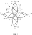
- FIG. 2 illustrates the flat configuration 14 of device 10 of FIG. 1 .
- the four petals 26 and the overall radial symmetry of the device can be seen.
- the peaks 30,31 of the curved inner rib are present, showing their residence in gap 27 of the petals 26.
- cutting from a sheet of metal rather than a cannula results in the ability to create more complex geometries such as the central hub 16, the inner rib 28, and the perforation preventing plates 34.
- FIG. 3 provides a side view of the device 10 of FIGs. 1 and 2 in expanded configuration 11.
- a self-expanding intravascular filter in accordance with the principles of the present disclosure can be made of a shape memory material.
- a shape memory material is a shape memory metal, in particular a class of nickel-titanium alloys, including those marketed under the name NITINOL. Such alloys are known for their shape memory and pseudoelastic properties.
- a shape memory material such a nickel-titanium alloy is able to undergo a reversible thermoelastic transformation between certain metallurgical phases.
- a device made from a shape memory material, in some embodiments a nickel-titanium alloy can be heat set to retain its shape after implantation.
- a filter device may be made of a stainless steel, such as stainless steel 304.
- the device is particularly envisioned to be of unitary construction.
- a device of unitary construction is made of a single piece of precursor material, such as a substantially planar sheet of metal.
- a sheet of a shape-memory metal such as a nickel-titanium alloy may be laser-cut to yield the filter device.
- Unitary construction and laser cutting allows for the use of a single pattern to generate the device without the complications and possibilities for introduction of error that derive from weaving, soldering, or using another method to connect separate parts into a unit.
- the term "unitary" means that the device is made of a single piece which has not been joined to another piece.
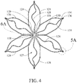
- FIG. 4 an alternative embodiment of a filter device in accordance with the principles of the present disclosure is attached. Numerous aspects of the device can be altered and fall within the principles of the invention. Regarding FIG. 4 , device 110 has six petals 126 radially surrounding the hub 116, and the barbs 136 are configured differently than the device of FIGs. 1-3 .
- FIG. 5A-C illustrate a number of barbs which will permit anchoring of a device to a vessel wall. In a preferred embodiment these barbs may be cut from the structure and bent outward.
- FIG. 5B illustrates barbs in accordance with embodiment shown in FIGs. 1-3 .
- the barb 36 is bent out of the plane of the rest of the device 10 and lies upstream of the pad structure 34.
- FIGS. 5A and 5C show barb configurations in which the barb is cut from a space within the pad structure.
- the barb 136 of FIG. 5A is formed from within pad structure 134 and points with its point in the downstream direction
- barb 536 of FIG. 5C is formed within pad structure 534 but points with its point in the upstream direction.
- the barb 136/536 will be bent out of the plane of the pad 134/534 in order that the barbs 136/536 can engage the wall of a vessel V into which the device 110/510 is implanted.
- Barbs may face the upstream direction, which will not interfere with retrieval. However, if a more secure hold is desired and the barbs are designed to be bent back such that their pointed ends point back in the downstream direction, the filter device, and particularly the petals, need to have a concave geometry so that retrieval can proceed as shown in FIG. 8B .
- the barb configurations shown in FIGs. 5A-5C can be combined with any other design of the filter device and still fall within the scope of the present invention.
- the barb configurations may vary on a petal-to-petal basis; that is, one petal may have a barb as in FIG. 5B , and the radially adjacent petal may include a barb as in FIG. 5A .
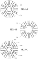
- FIG. 6A-C illustrate various structures that can be used at hubs.
- Hub 116 is similar to the hubs shown in the embodiments of FIGs. 1-4 , wherein the hub is a ring shape with an aperture 118 formed therethrough. As mentioned previously, this open aperture 118 may aid in simplifying retrieval of the filter device from a vessel to which it has been deployed, as a retrieval member such as a hook or a snare can be fed therethrough.
- the embodiment of FIG. 6C is similar, with the hub 316 having a polygonal shape, in this case a hexagonal aperture 318 with edges 317 is formed therethrough.
- FIG. 6B shows a device having hub 216, which is a closed circle 218.
- hub configuration may be preferred for an embodiment of a filter device which is not to be retrieved, and the closed end may assist in increasing the capacity of the filter to capture clots or emboli.
- a snare which targets a different portion of the filter device could be used, and therefore a device having hub 216 with closed circle 218 could still be a retrievable filter.
- the outer diameter of the hub 16/116/216/316 may be limited by the size of the sheath of the delivery system. In various embodiments, diameter of the hub may range from about 7 french to about 15 french, or from about 2.5 millimeters to about 5 millimeters.
- FIG. 7A a petal 126 in accordance with one embodiment of the present disclosure is illustrated.
- the petal is part of a device in a deployed configuration or an expanded configuration 170.
- the struts take on arcuate shape 120
- inner rib 128 takes on a sinuous shape, the inner rib 128 being curved such that curve peaks 129, 130, and 131 are evident.
- the curved rib increases clot capture area, increase radial force produced, strengthens the device, acts as a redundant feature in case of failure of a strut, and accommodates foreshortening.
- FIG. 7B shows the petal of FIG. 7A is shown in its compressed configuration 180 and is referred to as compressed petal 196.
- compressed petal 196 the typical situation in which a device of this construction will be in its compressed configuration is when the device is packed into and loaded in a delivery apparatus prior to delivery into the vasculature of a patient.
- compressive force 185 as applied to the device, and the struts take on straightened shape 190.
- the straightening of the inner rib 128 to substantially straight configuration 198 may be so extensive that the peaks of any curve may no longer be evident.
- FIG. 8A shows deployed device 410 in a blood vessel.
- Barbs 436 engage the wall of vessel V, and pad structures 434 prevent the barbs 436 from puncturing the vessel wall. Because the device is in deployed configuration 470, the inner rib 428 is sinuous in shape.
- retrieval sheath 450 has moved in direction 451 to capture the filter 410.
- an optional retrieval member such as a hook, for engaging the hub.
- the concave profile of the filter device 410 particularly owing to the shapes of petals 426, increases retrievability.
- the inner rib straightens to straight configuration 498, and the barbs 436 move toward the axial center of vessel V. This minimizes or prevents contact between the barbs 436 and the retrieval sheath 450, such that the points of the barbs do not damage the retrieval sheath 450.
- the barbs 436 may move through and past the longitudinal axis of the vessel V. Any variety of device configurations which avoid contact between the barbs 436 and the retrieval sheath are possible.
- the device may, optionally, further incorporate radiopaque markers to assist a physician with placement in the body.
- radiopaque markers may be made of materials including gold, palladium, tantalum, platinum, and biocompatible alloys of any of these materials.
- a device as disclosed herein may be used with many existing delivery systems as are known in the art. Particularly when a device is made of a shape memory metal such as a nickel-titanium alloy, the final dimensions of the device are determined by the remembered state and not dependent upon manipulating the delivery system to crimp or otherwise modify the device as it is being loaded.
- a shape memory metal such as a nickel-titanium alloy
- the filter device may be covered with a porous or non-porous layer which has drug-eluting properties. All coatings or biological coverings may be attached by any known method, including spray coating and the like.
- a device in accordance with the principles of the present disclosure may be made according to a series of steps, as illustrated in FIGs. 9A-9D .
- a single, monolithic, sheet of a shape memory alloy may be precisely laser cut to generate the overall shape of the filter device.
- FIG. 9A a device 610 in its flat configuration 614 has been placed at a distal end 626 of a substantially tubular mandrel 660.
- the device 610 makes contact at the open end of the tubular mandrel 660 at points of contact 671.
- FIG. 9B the device 610 has been drawn partially into the lumen of the tubular mandrel 660 by pulling in a direction 681 to form partially expanded configuration 680.
- FIG. 9C illustrates the continued effect of the pulling force in direction 681, which converts the device to partially expanded configuration 682.
- the device has achieved expanded configuration 611 due to the continued action of pulling force in direction 681.
- the device may be heat set by providing heat 669.
- the mandrel 660 may be a simple tubular structure, or it may be of a custom shape in order to achieve specific shapes of the device 610.
- the mandrel 660 of FIGs. 9A-9D is illustrated with a flared end 662 to give the mandrel 660 an overall trumpet-like shape.
- Many other configurations are possible, including frusto-conical mandrels, and so forth.
- shaping or bending the filter into its expanded configuration may include passing the filter device through a plurality of mandrels.
- a method of using a filter device as described in the instant disclosure can include a number of different steps.
- the filter device may be compressed to a compressed state and loaded into a delivery assembly.
- the delivery assembly may be introduced to the body percutaneously, and the device delivered, such as by a pusher, into the lumen of the body vessel, in one embodiment the vena cava, more particularly the inferior vena cava.
- the filter device upon deployment, will anchor against the vessel wall as it is deployed from the delivery assembly as it returns to its remembered, unconstrained state. For instance, in the illustration of the filter device deployed to a body vessel of FIG.
- the device after removal from the delivery assembly has returned to its unconstrained remembered state, leading to an expansion at the upstream, open end of the filter 410, with the barbs 436 engaging the vessel wall to secure the device within the vasculature. Delivery may be guided by imaging which may optionally include monitoring of one or more radiopaque portions included on the device. After the device has been secured within the body vessel, the delivery assembly is removed from the patient.
Landscapes
- Health & Medical Sciences (AREA)
- Engineering & Computer Science (AREA)
- Biomedical Technology (AREA)
- Cardiology (AREA)
- Oral & Maxillofacial Surgery (AREA)
- Transplantation (AREA)
- Heart & Thoracic Surgery (AREA)
- Vascular Medicine (AREA)
- Life Sciences & Earth Sciences (AREA)
- Animal Behavior & Ethology (AREA)
- General Health & Medical Sciences (AREA)
- Public Health (AREA)
- Veterinary Medicine (AREA)
- Mechanical Engineering (AREA)
- Surgical Instruments (AREA)
Abstract
Description
- This application claims the benefit of priority under 35 U.S.C. § 119(a) to
U.S. Provisional Application No. 62/270,821, filed December 22, 2015 - The present invention relates to medical devices. More particularly, the invention relates to a vena cava clot filter that can be percutaneously placed in the vena cava of a patient.
- A need for filtering devices arises in trauma patients, orthopedic surgery patients, neurosurgery patients, or in patients having medical conditions requiring bed rest or non-movement. During such medical conditions, the need for filtering devices arises due to the likelihood of thrombosis in the peripheral vasculature of patients wherein thrombi break away from the vessel wall, risking downstream embolism or embolization. For example, depending on the size, such thrombi pose a serious risk of pulmonary embolism wherein blood clots migrate from the peripheral vasculature through the heart and into the lungs.
- A filtering device can be deployed in the vena cava of a patient when, for example, anticoagulant therapy is contraindicated or has failed. Typically, filtering devices are permanent implants, each of which remains implanted in the patient for life, even though the condition or medical problem that required the device has passed. In more recent years, filters have been used or considered in preoperative patients and in patients predisposed to thrombosis which places the patient at risk for pulmonary embolism.
- Currently available vena cava filters generally include a number of struts formed from individual pieces of wire arranged to give the filter its shape and collected at one end by a separate piece that gathers the ends of the struts together, such as a collet, a bushing, or a sleeve, generally referred to as a hub. Although these devices are effective, their construction could be simplified.
- There is a need for filter devices which are simple to make and provide geometries that are efficacious for capturing emboli and clots.
- In one aspect, the present disclosure provides a filter device for implantation into a body vessel, the device having a hub; and a plurality of struts extending radially from the hub, each strut having a first end connected to the hub and extending radially therefrom to a second end, the second ends of two radially adjacent struts being connected at a tip to form a petal having a gap between the radially adjacent struts, each petal comprising an inner rib extending from the hub through the gap to the tip of the petal.
- In another aspect, the present disclosure describes a filter device for implantation into a body vessel, the device having a hub which is a center ring. The device also includes a plurality of struts extending radially from the hub, each strut having a first end connected to the hub and extending radially therefrom to a second end, the second ends of two radially adjacent struts being connected at a tip to form a petal having a gap between the radially adjacent struts, each petal comprising an inner rib extending from the hub through the gap to the tip of the petal. The device includes a pad at each petal tip for contacting the wall of the body vessel, each pad comprising a barb for engaging the wall of the body vessel. The filter device is of unitary construction and being cut from a substantially planar piece of a shape memory metal.
- In another embodiment, the present disclosure provides a method of making an intravascular filter device. The method includes steps of cutting a substantially planar piece of material to form a filter device, the filter device comprising a hub and a plurality of struts extending radially from the hub, each strut having a first end connected to the hub and extending radially therefrom to a second end, the second ends of two radially adjacent struts being connected at a tip to form a petal having a gap between the radially adjacent struts, each petal comprising an inner rib extending from the hub through the gap to the tip of the petal, the filter device being in a flat configuration; placing the filter device at a distal end of a tubular mandrel having a lumen formed therethrough, the mandrel having a proximal end and extending to the distal end; and pulling the filter device through the distal end in the proximal direction and into the lumen such that the filter device adopts a expanded configuration by contact with the mandrel.
- Further objects, features, and advantages of the present invention will become apparent from consideration of the following description and the appended claims when taken in connection with the accompanying drawings.
- The drawings are purely schematic illustrations of various aspects of the invention and are not necessarily to scale, unless expressly stated.
-
FIG. 1 is a perspective view of a filter in a expanded configuration or deployed configuration in accordance with one embodiment of the present invention; -
FIG. 2 is a view of the filter device ofFIG. 1 in its flat configuration in accordance with the principles of the present disclosure; -
FIG. 3 is a side view of the filter device ofFIGs. 1 and2 in its expanded or deployed configuration; -
FIG. 4 is a view of a second embodiment of a filter device in its flat configuration in accordance with the principles of the present disclosure; -
FIGs. 5A-5C are closeup views of barbs formed for a filter device in accordance with the principles of the present disclosure; -
FIGs. 6A-6C are closeup views of centers of various embodiments of filter devices in their flat configurations and which are constructed in accordance with an embodiment of the present disclosure; -
FIG. 7A is a side view of a petal of a filter device in its deployed configuration in accordance with an embodiment of the present disclosure; -
FIG. 7B is a side view of the petal ofFIG. 7A in its compressed configuration; -
FIG. 8A is a side view of a filter device deployed to a blood vessel and a retrieval sheath; -
FIG. 8B is a side view of the filter device ofFIG. 8A being pulled into the retrieval sheath; and -
FIGS. 9A-9D are side views of a filter device constructed in accordance with the principles of the present invention being converted from its flat configuration to its expanded configuration using a tubular mandrel in accordance with the principles of the present disclosure. - While the present invention has been described in terms of certain preferred embodiments, it will be understood that the invention is not limited to the disclosed embodiments, as those having skill in the art may make various modifications without departing from the scope of the following claims.
- The terms "substantially" or "about" used herein includes variations in the recited characteristic or quantity that are functionally equivalent to the quantity recited, such as an amount that is equivalent to the quantity recited for an intended purpose or function. In the case of a numerical quantity, the terms "substantially" or "about" shall mean a range consisting of a
value 20% less than the recited value to avalue 20% greater than the recited value, inclusive. - As used herein, the terms "upstream" and "downstream" particularly refer to the direction of blood flow through a vessel. Blood flows from upstream to downstream. Reference made to an upstream or downstream end or portion of a filter device is done with reference to the deployed configuration of the device, with blood moving from the upstream end toward the downstream end of the device when the device has been deployed to a blood vessel.
- As used herein, the terms "expanded configuration" and "deployed configuration" are to be understood as substantially interchangeable with regard to the shape of a filter device. Typically, the expanded configuration and the deployed configuration are substantially identical; "expanded" being used to describe the device when it has been shaped out of its flat configuration but not necessarily deployed to a body vessel, and "deployed" being used to describe a device which is resident in a blood vessel. A person of skill in the art will recognize that any dissimilarity between the expanded configuration and the deployed configuration will arise from the constraint applied by the wall of the vessel to which the filter device has been deployed.
- As used herein, the term "unitary construction" refers to the structural components of a filter device, such as a strut, a hub, a barb, a pad structure, all being formed from the same piece of precursor material, preferably a substantially planar piece of a metal, the metal preferably being a shape memory alloy. Non-structural components, such as coatings, radiopaque markers, and the like, may be added to the device without detracting from the unitary construction of the structure of the device.
-
FIG. 1 illustrates a first embodiment of afilter device 10 in accordance with the principles of the present disclosure. Thefilter device 10 is shown in its expandedconfiguration 11 and comprises a plurality ofstruts 12, which each have afirst end 37 attached to a center orhub 16. It should be noted that unlike certain devices already known in the art, thehub 16 is not a separately-formed piece which gathers ends of struts in, for instance, a collet or a sleeve; rather, as used herein, a hub is a portion of a unitary device from which struts generally emanate. - The
struts 12 extend fromfirst ends 37, which are connected to thehub 16, radially outward tosecond ends 38. In one embodiment, thestruts 12 comprisefirst segments 20 and angle atsecond segments 24. In one embodiment, thefirst segments 20 of two radiallyadjacent struts 12 are conjoined, as illustrated inFIG. 1 , butfirst segments 20 may be formed separately from one another as well. In the embodiment ofFIG. 1 , thefirst segments 20 disjoin and angle to formsecond segments 24 atsplit 22. - Two radially
adjacent struts 12 comprisepetals 26. Thepetals 26 each define agap 27 between the two radiallyadjacent struts 12, with the second ends 38 ofstruts 12 converging attip 32. It is noted that inFIG. 1 , the radiallyadjacent struts 12 that have conjoinedfirst segments 20 form portions of twodifferent petals 26, and thestruts 12 which form asingle petal 26 are not conjoined at their first segments. - As shown in
FIG. 1 , the device comprises fourpetals 26. However, other numbers of petals are possible when the device has radial symmetry, including three petals, five petals, six petals, seven petals, eight petals, nine petals, 10 petals, 11 petals, 12 petals, 14 petals, 16 petals, 18 petals, 20 petals, 22 petals, and 24 petals. -
Pad structure 34 is present attip 32 ofpetal 26 in the embodiment ofFIG. 1 . The pad structure is a perforation preventing pad, and is designed to lay flat against the wall of a vessel to which the filter device has been deployed in order to allow thebarbs 36 of the device to engage the wall, but not perforate it to such a degree to cause injury. As shown inFIG. 1 , thepad structure 34 is shown as oval or elliptical in shape, but any polygonal or ring shape can be employed so long as the function of thepad 34 is retained. -
Barb 36 ofdevice 10 ofFIG. 1 is located downstream ofpad structure 34. Thebarbs 36 of this disclosure will be described in detail with regard toFIGs. 5A-C . The function of thebarbs 36 is to engage the wall of the vessel in order to prevent migration of the device. - The
inner rib 28 is located ingap 27 ofpetal 26. Theinner rib 28 extends fromhub 16 to tip 32, and comprises curves withpeaks struts 12. - The
inner rib 28 provides thefilter device 10 with a number of abilities. Foremost, eachinner rib 28 adds a solid portion within eachpetal 26, providing more connections tohub 16 and thus providing thefilter device 10 with more surface area on which to catch smaller clots or emboli. Theinner rib 28, because of its curved nature, also serves to accommodate foreshortening when thefilter device 10 is put into its compressed configuration and loaded into a delivery system. The curvature of theinner rib 28 provides sufficient slack for packaging of thedevice 10, but is not so long as to increase the profile of the device in the compressed configuration. As will be shown later,inner rib 28 straightens when the device is in its compressed form in the delivery device. - The
inner rib 28 may be of a number of designs. In one embodiment, it is sinuous and curved but does not have three peaks. Theinner rib 28 may be of any configuration as long as the length ofinner rib 28 is greater than or equal to the length of thepetal 26 in which it resides when the device is in its compressed configuration. - The
inner rib 28 reinforces thefilter device 10 and provides additional radial force against the wall of a vessel to which thefilter device 10 has been deployed. As a result, filter apposition is improved, and the chances of migration of the filter are minimized. Further, theinner rib 28 may serve as a redundant structure; should a strut of thepetal 26 in which theinner rib 28 resides fail for any reason, thefilter device 10 should still function and remain in place, and will still be retrievable. - The
hub 16, as shown inFIG. 1 , is a ring withempty center 18. Alternate designs are possible and will be described later. Anempty center 18 will be accommodating of retrievability, such that a retrieval assembly with an element such as a hook will be able to engage the center and snare thefilter device 10 so as to more surely guarantee retrieval. - In another embodiment, the
empty center 18 may be provided such that a retrieval member may be attached to the device after assembly of thefilter device 10. Such a retrieval member may be, for instance, a hook that can be fit through theempty center 18 and welded or soldered into place. This would allow for simplified grasping by a retrieval snare. -
FIG. 2 illustrates theflat configuration 14 ofdevice 10 ofFIG. 1 . In this illustration, the fourpetals 26 and the overall radial symmetry of the device can be seen. Thepeaks gap 27 of thepetals 26. Overall, cutting from a sheet of metal rather than a cannula results in the ability to create more complex geometries such as thecentral hub 16, theinner rib 28, and theperforation preventing plates 34.FIG. 3 provides a side view of thedevice 10 ofFIGs. 1 and2 in expandedconfiguration 11. - In one embodiment, a self-expanding intravascular filter in accordance with the principles of the present disclosure can be made of a shape memory material. One example of a shape memory material is a shape memory metal, in particular a class of nickel-titanium alloys, including those marketed under the name NITINOL. Such alloys are known for their shape memory and pseudoelastic properties. As a shape memory material, such a nickel-titanium alloy is able to undergo a reversible thermoelastic transformation between certain metallurgical phases. A device made from a shape memory material, in some embodiments a nickel-titanium alloy, can be heat set to retain its shape after implantation.
- In another embodiment, a filter device may be made of a stainless steel, such as stainless steel 304.
- The device is particularly envisioned to be of unitary construction. In one sense, a device of unitary construction is made of a single piece of precursor material, such as a substantially planar sheet of metal. Specifically, a sheet of a shape-memory metal such as a nickel-titanium alloy may be laser-cut to yield the filter device. Unitary construction and laser cutting allows for the use of a single pattern to generate the device without the complications and possibilities for introduction of error that derive from weaving, soldering, or using another method to connect separate parts into a unit. As used herein, the term "unitary" means that the device is made of a single piece which has not been joined to another piece.
- Turning now to
FIG. 4 , an alternative embodiment of a filter device in accordance with the principles of the present disclosure is attached. Numerous aspects of the device can be altered and fall within the principles of the invention. RegardingFIG. 4 , device 110 has sixpetals 126 radially surrounding thehub 116, and thebarbs 136 are configured differently than the device ofFIGs. 1-3 . - To further support the anchoring of the filter device to the vessel, hooks or barbs may be incorporated onto the outer surface of the device.
FIG. 5A-C illustrate a number of barbs which will permit anchoring of a device to a vessel wall. In a preferred embodiment these barbs may be cut from the structure and bent outward. -
FIG. 5B illustrates barbs in accordance with embodiment shown inFIGs. 1-3 . Here, thebarb 36 is bent out of the plane of the rest of thedevice 10 and lies upstream of thepad structure 34. -
FIGS. 5A and 5C show barb configurations in which the barb is cut from a space within the pad structure. Thebarb 136 ofFIG. 5A is formed from withinpad structure 134 and points with its point in the downstream direction, whereasbarb 536 ofFIG. 5C is formed withinpad structure 534 but points with its point in the upstream direction. In either case, thebarb 136/536 will be bent out of the plane of thepad 134/534 in order that thebarbs 136/536 can engage the wall of a vessel V into which the device 110/510 is implanted. - Barbs may face the upstream direction, which will not interfere with retrieval. However, if a more secure hold is desired and the barbs are designed to be bent back such that their pointed ends point back in the downstream direction, the filter device, and particularly the petals, need to have a concave geometry so that retrieval can proceed as shown in
FIG. 8B . - It is intended that any of the barb configurations shown in
FIGs. 5A-5C can be combined with any other design of the filter device and still fall within the scope of the present invention. In one embodiment, the barb configurations may vary on a petal-to-petal basis; that is, one petal may have a barb as inFIG. 5B , and the radially adjacent petal may include a barb as inFIG. 5A . -
FIG. 6A-C illustrate various structures that can be used at hubs.Hub 116 is similar to the hubs shown in the embodiments ofFIGs. 1-4 , wherein the hub is a ring shape with anaperture 118 formed therethrough. As mentioned previously, thisopen aperture 118 may aid in simplifying retrieval of the filter device from a vessel to which it has been deployed, as a retrieval member such as a hook or a snare can be fed therethrough. The embodiment ofFIG. 6C is similar, with thehub 316 having a polygonal shape, in this case ahexagonal aperture 318 withedges 317 is formed therethrough. -
FIG. 6B shows adevice having hub 216, which is aclosed circle 218. Such a hub configuration may be preferred for an embodiment of a filter device which is not to be retrieved, and the closed end may assist in increasing the capacity of the filter to capture clots or emboli. However, a snare which targets a different portion of the filter device could be used, and therefore adevice having hub 216 withclosed circle 218 could still be a retrievable filter. - The outer diameter of the
hub 16/116/216/316 may be limited by the size of the sheath of the delivery system. In various embodiments, diameter of the hub may range from about 7 french to about 15 french, or from about 2.5 millimeters to about 5 millimeters. - Turning now to
FIG. 7A , apetal 126 in accordance with one embodiment of the present disclosure is illustrated. The petal is part of a device in a deployed configuration or an expandedconfiguration 170. When the device is in this configuration, the struts take onarcuate shape 120, andinner rib 128 takes on a sinuous shape, theinner rib 128 being curved such that curve peaks 129, 130, and 131 are evident. As mentioned previously, the curved rib increases clot capture area, increase radial force produced, strengthens the device, acts as a redundant feature in case of failure of a strut, and accommodates foreshortening. - In contrast,
FIG. 7B shows the petal ofFIG. 7A is shown in itscompressed configuration 180 and is referred to ascompressed petal 196. As mentioned previously, the typical situation in which a device of this construction will be in its compressed configuration is when the device is packed into and loaded in a delivery apparatus prior to delivery into the vasculature of a patient. In this configuration,compressive force 185 as applied to the device, and the struts take on straightenedshape 190. Notable is the straightening of theinner rib 128 to substantiallystraight configuration 198. In some cases, such as that illustrated, the straightening may be so extensive that the peaks of any curve may no longer be evident. - With regard to retrieval of the device,
FIG. 8A shows deployeddevice 410 in a blood vessel.Barbs 436 engage the wall of vessel V, andpad structures 434 prevent thebarbs 436 from puncturing the vessel wall. Because the device is in deployedconfiguration 470, theinner rib 428 is sinuous in shape. - In
FIG. 8B ,retrieval sheath 450 has moved indirection 451 to capture thefilter 410. Not shown is an optional retrieval member, such as a hook, for engaging the hub. The concave profile of thefilter device 410, particularly owing to the shapes ofpetals 426, increases retrievability. During retrieval, the inner rib straightens tostraight configuration 498, and thebarbs 436 move toward the axial center of vessel V. This minimizes or prevents contact between thebarbs 436 and theretrieval sheath 450, such that the points of the barbs do not damage theretrieval sheath 450. In some embodiments, thebarbs 436 may move through and past the longitudinal axis of the vessel V. Any variety of device configurations which avoid contact between thebarbs 436 and the retrieval sheath are possible. - The device may, optionally, further incorporate radiopaque markers to assist a physician with placement in the body. Many suitable radiopaque materials are known and any of these may be selected for use with a device of the present disclosure. The radiopaque markers may be made of materials including gold, palladium, tantalum, platinum, and biocompatible alloys of any of these materials.
- Further, a device as disclosed herein may be used with many existing delivery systems as are known in the art. Particularly when a device is made of a shape memory metal such as a nickel-titanium alloy, the final dimensions of the device are determined by the remembered state and not dependent upon manipulating the delivery system to crimp or otherwise modify the device as it is being loaded.
- Many possible variations on a device of this construction are also possible. If desired, the filter device may be covered with a porous or non-porous layer which has drug-eluting properties. All coatings or biological coverings may be attached by any known method, including spray coating and the like.
- A device in accordance with the principles of the present disclosure may be made according to a series of steps, as illustrated in
FIGs. 9A-9D . As mentioned previously, a single, monolithic, sheet of a shape memory alloy may be precisely laser cut to generate the overall shape of the filter device. - In
FIG. 9A , adevice 610 in its flat configuration 614 has been placed at adistal end 626 of a substantiallytubular mandrel 660. Thedevice 610 makes contact at the open end of thetubular mandrel 660 at points ofcontact 671. InFIG. 9B , thedevice 610 has been drawn partially into the lumen of thetubular mandrel 660 by pulling in adirection 681 to form partially expandedconfiguration 680.FIG. 9C illustrates the continued effect of the pulling force indirection 681, which converts the device to partially expandedconfiguration 682. Finally, inFIG. 9D , the device has achieved expandedconfiguration 611 due to the continued action of pulling force indirection 681. Optionally, and particularly when a shape memory alloy is used for the device, the device may be heat set by providingheat 669. - The
mandrel 660 may be a simple tubular structure, or it may be of a custom shape in order to achieve specific shapes of thedevice 610. For example, themandrel 660 ofFIGs. 9A-9D is illustrated with a flaredend 662 to give themandrel 660 an overall trumpet-like shape. Many other configurations are possible, including frusto-conical mandrels, and so forth. - In some embodiments, shaping or bending the filter into its expanded configuration may include passing the filter device through a plurality of mandrels.
- A method of using a filter device as described in the instant disclosure can include a number of different steps. In one step, the filter device may be compressed to a compressed state and loaded into a delivery assembly. The delivery assembly may be introduced to the body percutaneously, and the device delivered, such as by a pusher, into the lumen of the body vessel, in one embodiment the vena cava, more particularly the inferior vena cava. The filter device, upon deployment, will anchor against the vessel wall as it is deployed from the delivery assembly as it returns to its remembered, unconstrained state. For instance, in the illustration of the filter device deployed to a body vessel of
FIG. 8A , the device after removal from the delivery assembly has returned to its unconstrained remembered state, leading to an expansion at the upstream, open end of thefilter 410, with thebarbs 436 engaging the vessel wall to secure the device within the vasculature. Delivery may be guided by imaging which may optionally include monitoring of one or more radiopaque portions included on the device. After the device has been secured within the body vessel, the delivery assembly is removed from the patient. - While the present invention has been described in terms of certain preferred embodiments, it will be understood that the invention is not limited to the disclosed embodiments, as those having skill in the art may make various modifications without departing from the scope of the following claims.
Claims (15)
- A filter device for implantation into a body vessel, the device comprising:a hub; anda plurality of struts extending radially from the hub, each strut having a first end connected to the hub and extending radially therefrom to a second end, the second ends of two radially adjacent struts being connected at a tip to form a petal having a gap between the radially adjacent struts, each petal comprising an inner rib extending from the hub through the gap to the tip of the petal.
- The filter device according to claim 1 wherein the filter device is of unitary construction and preferably being cut from a substantially planar piece of a shape memory metal.
- The filter device according to claim 1 or claim 2 wherein the filter device comprises a shape memory material, preferably a nickel-titanium alloy.
- The filter device according to any one of the preceding claims comprising a barb at each tip.
- The filter device according to any one of the preceding claims further comprising a pad structure adjacent a tip of a petal, a barb preferably being formed by a plurality of cuts of the pad structure.
- The filter device according to any one of the preceding claims having a deployed state and a compressed state, the inner rib comprising a curve in the deployed state and being substantially straight in the compressed state.
- The filter device according to any one of the preceding claims wherein the struts have an arcuate shape.
- The filter device according to any one of the preceding claims wherein the hub is a ring or a solid circle.
- The filter device according to any one of the preceding claims wherein each strut comprises a first segment extending from the first end away from the hub, each first segment being conjoined with a radially adjacent first segment.
- The filter device according to claim 9 wherein the first segments that are conjoined are portions of two petals.
- A method of forming a filter device for implantation into a body vessel, the method comprising:cutting a substantially planar piece of material to form a filter device, the filter device comprising a hub and a plurality of struts extending radially from the hub, each strut having a first end connected to the hub and extending radially therefrom to a second end, the second ends of two radially adjacent struts being connected at a tip to form a petal having a gap between the radially adjacent struts, each petal comprising an inner rib extending from the hub through the gap to the tip of the petal, the filter device being in a planar configuration; andbending the filter device to form an expanded configuration.
- The method according to claim 11 wherein bending the filter device comprises placing the filter device in a planar configuration at a distal end of a tubular mandrel having a lumen formed therethrough, the mandrel having a proximal end and extending to the distal end; and
moving the filter device through the distal end into the lumen and toward the proximal end such that the filter device adopts the expanded configuration by contact with the mandrel. - The method according to claim 11 or claim 12 wherein the filter device is moved through a plurality of mandrels.
- The method according to any one of claims 11 to 13 further comprising a heat setting step.
- The method according to any one of claims 11 to 14 further comprising cutting a barb in the filter device and preferably bending the barb outward.
Applications Claiming Priority (1)
| Application Number | Priority Date | Filing Date | Title |
|---|---|---|---|
| US201562270821P | 2015-12-22 | 2015-12-22 |
Publications (2)
| Publication Number | Publication Date |
|---|---|
| EP3184077A1 true EP3184077A1 (en) | 2017-06-28 |
| EP3184077B1 EP3184077B1 (en) | 2021-09-22 |
Family
ID=57517768
Family Applications (1)
| Application Number | Title | Priority Date | Filing Date |
|---|---|---|---|
| EP16202543.1A Active EP3184077B1 (en) | 2015-12-22 | 2016-12-06 | Filter device for implantation into a body vessel |
Country Status (2)
| Country | Link |
|---|---|
| US (2) | US10456233B2 (en) |
| EP (1) | EP3184077B1 (en) |
Cited By (1)
| Publication number | Priority date | Publication date | Assignee | Title |
|---|---|---|---|---|
| CN112638318A (en) * | 2018-09-28 | 2021-04-09 | 泰尔茂株式会社 | Filter device |
Families Citing this family (3)
| Publication number | Priority date | Publication date | Assignee | Title |
|---|---|---|---|---|
| CN107693162A (en) * | 2017-11-07 | 2018-02-16 | 北京东方美通科技有限公司 | The convenient recovery vena cava filter of one kind |
| WO2023038929A1 (en) | 2021-09-08 | 2023-03-16 | Boston Scientific Scimed, Inc. | Occlusive implant with multi-sharpness split tip soft tissue anchors |
| US20250064573A1 (en) * | 2021-12-30 | 2025-02-27 | Bard Peripheral Vascular, Inc. | Vascular Implant |
Citations (4)
| Publication number | Priority date | Publication date | Assignee | Title |
|---|---|---|---|---|
| US20080039891A1 (en) * | 2004-01-22 | 2008-02-14 | Rex Medical | Vein filter |
| US20100121373A1 (en) * | 2008-11-10 | 2010-05-13 | Cook Incorporated | Removable vena cava filter with improved leg |
| EP2626106A1 (en) * | 2002-10-17 | 2013-08-14 | Gore Enterprise Holdings, Inc. | Embolic filter frame |
| US20140348860A1 (en) * | 2012-02-13 | 2014-11-27 | Cook Medical Technologies Llc | Medical devices for collecting pathogenic cells |
Family Cites Families (13)
| Publication number | Priority date | Publication date | Assignee | Title |
|---|---|---|---|---|
| US20070203520A1 (en) * | 1995-06-07 | 2007-08-30 | Dennis Griffin | Endovascular filter |
| DE69716779T2 (en) | 1996-01-30 | 2003-07-17 | Medtronic, Inc. | PRODUCTS AND METHOD FOR PRODUCING DILATERS |
| US6152946A (en) | 1998-03-05 | 2000-11-28 | Scimed Life Systems, Inc. | Distal protection device and method |
| US6099534A (en) | 1997-10-01 | 2000-08-08 | Scimed Life Systems, Inc. | Releasable basket |
| US20030187495A1 (en) | 2002-04-01 | 2003-10-02 | Cully Edward H. | Endoluminal devices, embolic filters, methods of manufacture and use |
| US6881218B2 (en) | 2002-05-01 | 2005-04-19 | Angiodynamics, Inc. | Blood clot filter |
| US7625399B2 (en) | 2003-04-24 | 2009-12-01 | Cook Incorporated | Intralumenally-implantable frames |
| US7722635B2 (en) | 2004-06-25 | 2010-05-25 | Angiodynamics, Inc. | Blood clot filter |
| DE102005040214A1 (en) | 2005-08-15 | 2007-03-01 | Epflex Feinwerktechnik Gmbh | Multi-wire unit and manufacturing method thereof |
| WO2007061927A2 (en) * | 2005-11-18 | 2007-05-31 | C. R. Bard, Inc. | Vena cava filter with filament |
| WO2007133366A2 (en) | 2006-05-02 | 2007-11-22 | C. R. Bard, Inc. | Vena cava filter formed from a sheet |
| WO2013049448A1 (en) | 2011-09-29 | 2013-04-04 | Covidien Lp | Vascular remodeling device |
| CN107260361A (en) | 2012-07-25 | 2017-10-20 | 诺瓦特医疗有限公司 | Vascular filter device |
-
2016
- 2016-12-06 US US15/370,382 patent/US10456233B2/en active Active
- 2016-12-06 EP EP16202543.1A patent/EP3184077B1/en active Active
-
2019
- 2019-10-29 US US16/666,562 patent/US11413130B2/en active Active
Patent Citations (4)
| Publication number | Priority date | Publication date | Assignee | Title |
|---|---|---|---|---|
| EP2626106A1 (en) * | 2002-10-17 | 2013-08-14 | Gore Enterprise Holdings, Inc. | Embolic filter frame |
| US20080039891A1 (en) * | 2004-01-22 | 2008-02-14 | Rex Medical | Vein filter |
| US20100121373A1 (en) * | 2008-11-10 | 2010-05-13 | Cook Incorporated | Removable vena cava filter with improved leg |
| US20140348860A1 (en) * | 2012-02-13 | 2014-11-27 | Cook Medical Technologies Llc | Medical devices for collecting pathogenic cells |
Cited By (2)
| Publication number | Priority date | Publication date | Assignee | Title |
|---|---|---|---|---|
| CN112638318A (en) * | 2018-09-28 | 2021-04-09 | 泰尔茂株式会社 | Filter device |
| CN112638318B (en) * | 2018-09-28 | 2024-01-12 | 泰尔茂株式会社 | Filtering equipment |
Also Published As
| Publication number | Publication date |
|---|---|
| US10456233B2 (en) | 2019-10-29 |
| US20200060801A1 (en) | 2020-02-27 |
| US11413130B2 (en) | 2022-08-16 |
| EP3184077B1 (en) | 2021-09-22 |
| US20170172721A1 (en) | 2017-06-22 |
Similar Documents
| Publication | Publication Date | Title |
|---|---|---|
| JP6745848B2 (en) | Clot collection device for removing occluded clots from blood vessels | |
| US6273900B1 (en) | Blood clot filtering | |
| US6214025B1 (en) | Self-centering, self-expanding and retrievable vena cava filter | |
| US11413130B2 (en) | Intravascular filter cut from sheet metal | |
| US4793348A (en) | Balloon expandable vena cava filter to prevent migration of lower extremity venous clots into the pulmonary circulation | |
| US20130131714A1 (en) | Embolic protection device and methods of making the same | |
| EP2916747B1 (en) | Multi-pivot thrombectomy device | |
| CN103917197B (en) | Endoluminal device and the method preparing endoluminal device | |
| US20060206138A1 (en) | Intravascular filter assembly | |
| US7794473B2 (en) | Filter delivery system | |
| JP5559063B2 (en) | Stent design for use with one or more trigger wires | |
| JP2008511342A (en) | Retrievable intravascular filter with a bendable fixation member | |
| US20060095068A1 (en) | Retrievable vena cava filter | |
| US20100121373A1 (en) | Removable vena cava filter with improved leg | |
| US10507023B2 (en) | Self-centering spiral filter | |
| JP2007532267A5 (en) | ||
| EP1814488A1 (en) | Blood clot filter configured for a wire guide | |
| EP2926768B1 (en) | Vascular filter | |
| EP3861939B1 (en) | Aneurysm implant support device | |
| JP2024528063A (en) | Obstacle Removal System | |
| EP2918244A1 (en) | Vein filter |
Legal Events
| Date | Code | Title | Description |
|---|---|---|---|
| PUAI | Public reference made under article 153(3) epc to a published international application that has entered the european phase |
Free format text: ORIGINAL CODE: 0009012 |
|
| STAA | Information on the status of an ep patent application or granted ep patent |
Free format text: STATUS: THE APPLICATION HAS BEEN PUBLISHED |
|
| AK | Designated contracting states |
Kind code of ref document: A1 Designated state(s): AL AT BE BG CH CY CZ DE DK EE ES FI FR GB GR HR HU IE IS IT LI LT LU LV MC MK MT NL NO PL PT RO RS SE SI SK SM TR |
|
| AX | Request for extension of the european patent |
Extension state: BA ME |
|
| STAA | Information on the status of an ep patent application or granted ep patent |
Free format text: STATUS: REQUEST FOR EXAMINATION WAS MADE |
|
| 17P | Request for examination filed |
Effective date: 20171220 |
|
| RBV | Designated contracting states (corrected) |
Designated state(s): AL AT BE BG CH CY CZ DE DK EE ES FI FR GB GR HR HU IE IS IT LI LT LU LV MC MK MT NL NO PL PT RO RS SE SI SK SM TR |
|
| RIC1 | Information provided on ipc code assigned before grant |
Ipc: A61F 2/01 20060101AFI20200526BHEP |
|
| GRAP | Despatch of communication of intention to grant a patent |
Free format text: ORIGINAL CODE: EPIDOSNIGR1 |
|
| STAA | Information on the status of an ep patent application or granted ep patent |
Free format text: STATUS: GRANT OF PATENT IS INTENDED |
|
| INTG | Intention to grant announced |
Effective date: 20200703 |
|
| GRAJ | Information related to disapproval of communication of intention to grant by the applicant or resumption of examination proceedings by the epo deleted |
Free format text: ORIGINAL CODE: EPIDOSDIGR1 |
|
| STAA | Information on the status of an ep patent application or granted ep patent |
Free format text: STATUS: REQUEST FOR EXAMINATION WAS MADE |
|
| INTC | Intention to grant announced (deleted) | ||
| GRAP | Despatch of communication of intention to grant a patent |
Free format text: ORIGINAL CODE: EPIDOSNIGR1 |
|
| STAA | Information on the status of an ep patent application or granted ep patent |
Free format text: STATUS: GRANT OF PATENT IS INTENDED |
|
| INTG | Intention to grant announced |
Effective date: 20201125 |
|
| GRAJ | Information related to disapproval of communication of intention to grant by the applicant or resumption of examination proceedings by the epo deleted |
Free format text: ORIGINAL CODE: EPIDOSDIGR1 |
|
| STAA | Information on the status of an ep patent application or granted ep patent |
Free format text: STATUS: REQUEST FOR EXAMINATION WAS MADE |
|
| GRAP | Despatch of communication of intention to grant a patent |
Free format text: ORIGINAL CODE: EPIDOSNIGR1 |
|
| STAA | Information on the status of an ep patent application or granted ep patent |
Free format text: STATUS: GRANT OF PATENT IS INTENDED |
|
| INTC | Intention to grant announced (deleted) | ||
| INTG | Intention to grant announced |
Effective date: 20210503 |
|
| GRAS | Grant fee paid |
Free format text: ORIGINAL CODE: EPIDOSNIGR3 |
|
| GRAA | (expected) grant |
Free format text: ORIGINAL CODE: 0009210 |
|
| STAA | Information on the status of an ep patent application or granted ep patent |
Free format text: STATUS: THE PATENT HAS BEEN GRANTED |
|
| AK | Designated contracting states |
Kind code of ref document: B1 Designated state(s): AL AT BE BG CH CY CZ DE DK EE ES FI FR GB GR HR HU IE IS IT LI LT LU LV MC MK MT NL NO PL PT RO RS SE SI SK SM TR |
|
| REG | Reference to a national code |
Ref country code: GB Ref legal event code: FG4D |
|
| REG | Reference to a national code |
Ref country code: DE Ref legal event code: R096 Ref document number: 602016063954 Country of ref document: DE |
|
| REG | Reference to a national code |
Ref country code: IE Ref legal event code: FG4D |
|
| REG | Reference to a national code |
Ref country code: CH Ref legal event code: EP Ref country code: AT Ref legal event code: REF Ref document number: 1431712 Country of ref document: AT Kind code of ref document: T Effective date: 20211015 |
|
| REG | Reference to a national code |
Ref country code: LT Ref legal event code: MG9D |
|
| REG | Reference to a national code |
Ref country code: NL Ref legal event code: MP Effective date: 20210922 |
|
| PG25 | Lapsed in a contracting state [announced via postgrant information from national office to epo] |
Ref country code: HR Free format text: LAPSE BECAUSE OF FAILURE TO SUBMIT A TRANSLATION OF THE DESCRIPTION OR TO PAY THE FEE WITHIN THE PRESCRIBED TIME-LIMIT Effective date: 20210922 Ref country code: SE Free format text: LAPSE BECAUSE OF FAILURE TO SUBMIT A TRANSLATION OF THE DESCRIPTION OR TO PAY THE FEE WITHIN THE PRESCRIBED TIME-LIMIT Effective date: 20210922 Ref country code: RS Free format text: LAPSE BECAUSE OF FAILURE TO SUBMIT A TRANSLATION OF THE DESCRIPTION OR TO PAY THE FEE WITHIN THE PRESCRIBED TIME-LIMIT Effective date: 20210922 Ref country code: LT Free format text: LAPSE BECAUSE OF FAILURE TO SUBMIT A TRANSLATION OF THE DESCRIPTION OR TO PAY THE FEE WITHIN THE PRESCRIBED TIME-LIMIT Effective date: 20210922 Ref country code: BG Free format text: LAPSE BECAUSE OF FAILURE TO SUBMIT A TRANSLATION OF THE DESCRIPTION OR TO PAY THE FEE WITHIN THE PRESCRIBED TIME-LIMIT Effective date: 20211222 Ref country code: NO Free format text: LAPSE BECAUSE OF FAILURE TO SUBMIT A TRANSLATION OF THE DESCRIPTION OR TO PAY THE FEE WITHIN THE PRESCRIBED TIME-LIMIT Effective date: 20211222 Ref country code: FI Free format text: LAPSE BECAUSE OF FAILURE TO SUBMIT A TRANSLATION OF THE DESCRIPTION OR TO PAY THE FEE WITHIN THE PRESCRIBED TIME-LIMIT Effective date: 20210922 |
|
| REG | Reference to a national code |
Ref country code: AT Ref legal event code: MK05 Ref document number: 1431712 Country of ref document: AT Kind code of ref document: T Effective date: 20210922 |
|
| PG25 | Lapsed in a contracting state [announced via postgrant information from national office to epo] |
Ref country code: LV Free format text: LAPSE BECAUSE OF FAILURE TO SUBMIT A TRANSLATION OF THE DESCRIPTION OR TO PAY THE FEE WITHIN THE PRESCRIBED TIME-LIMIT Effective date: 20210922 Ref country code: GR Free format text: LAPSE BECAUSE OF FAILURE TO SUBMIT A TRANSLATION OF THE DESCRIPTION OR TO PAY THE FEE WITHIN THE PRESCRIBED TIME-LIMIT Effective date: 20211223 |
|
| PG25 | Lapsed in a contracting state [announced via postgrant information from national office to epo] |
Ref country code: AT Free format text: LAPSE BECAUSE OF FAILURE TO SUBMIT A TRANSLATION OF THE DESCRIPTION OR TO PAY THE FEE WITHIN THE PRESCRIBED TIME-LIMIT Effective date: 20210922 |
|
| PG25 | Lapsed in a contracting state [announced via postgrant information from national office to epo] |
Ref country code: IS Free format text: LAPSE BECAUSE OF FAILURE TO SUBMIT A TRANSLATION OF THE DESCRIPTION OR TO PAY THE FEE WITHIN THE PRESCRIBED TIME-LIMIT Effective date: 20220122 Ref country code: SK Free format text: LAPSE BECAUSE OF FAILURE TO SUBMIT A TRANSLATION OF THE DESCRIPTION OR TO PAY THE FEE WITHIN THE PRESCRIBED TIME-LIMIT Effective date: 20210922 Ref country code: RO Free format text: LAPSE BECAUSE OF FAILURE TO SUBMIT A TRANSLATION OF THE DESCRIPTION OR TO PAY THE FEE WITHIN THE PRESCRIBED TIME-LIMIT Effective date: 20210922 Ref country code: PT Free format text: LAPSE BECAUSE OF FAILURE TO SUBMIT A TRANSLATION OF THE DESCRIPTION OR TO PAY THE FEE WITHIN THE PRESCRIBED TIME-LIMIT Effective date: 20220124 Ref country code: PL Free format text: LAPSE BECAUSE OF FAILURE TO SUBMIT A TRANSLATION OF THE DESCRIPTION OR TO PAY THE FEE WITHIN THE PRESCRIBED TIME-LIMIT Effective date: 20210922 Ref country code: NL Free format text: LAPSE BECAUSE OF FAILURE TO SUBMIT A TRANSLATION OF THE DESCRIPTION OR TO PAY THE FEE WITHIN THE PRESCRIBED TIME-LIMIT Effective date: 20210922 Ref country code: ES Free format text: LAPSE BECAUSE OF FAILURE TO SUBMIT A TRANSLATION OF THE DESCRIPTION OR TO PAY THE FEE WITHIN THE PRESCRIBED TIME-LIMIT Effective date: 20210922 Ref country code: EE Free format text: LAPSE BECAUSE OF FAILURE TO SUBMIT A TRANSLATION OF THE DESCRIPTION OR TO PAY THE FEE WITHIN THE PRESCRIBED TIME-LIMIT Effective date: 20210922 Ref country code: CZ Free format text: LAPSE BECAUSE OF FAILURE TO SUBMIT A TRANSLATION OF THE DESCRIPTION OR TO PAY THE FEE WITHIN THE PRESCRIBED TIME-LIMIT Effective date: 20210922 Ref country code: AL Free format text: LAPSE BECAUSE OF FAILURE TO SUBMIT A TRANSLATION OF THE DESCRIPTION OR TO PAY THE FEE WITHIN THE PRESCRIBED TIME-LIMIT Effective date: 20210922 |
|
| REG | Reference to a national code |
Ref country code: DE Ref legal event code: R097 Ref document number: 602016063954 Country of ref document: DE |
|
| PG25 | Lapsed in a contracting state [announced via postgrant information from national office to epo] |
Ref country code: MC Free format text: LAPSE BECAUSE OF FAILURE TO SUBMIT A TRANSLATION OF THE DESCRIPTION OR TO PAY THE FEE WITHIN THE PRESCRIBED TIME-LIMIT Effective date: 20210922 Ref country code: DK Free format text: LAPSE BECAUSE OF FAILURE TO SUBMIT A TRANSLATION OF THE DESCRIPTION OR TO PAY THE FEE WITHIN THE PRESCRIBED TIME-LIMIT Effective date: 20210922 |
|
| PLBE | No opposition filed within time limit |
Free format text: ORIGINAL CODE: 0009261 |
|
| REG | Reference to a national code |
Ref country code: CH Ref legal event code: PL |
|
| STAA | Information on the status of an ep patent application or granted ep patent |
Free format text: STATUS: NO OPPOSITION FILED WITHIN TIME LIMIT |
|
| 26N | No opposition filed |
Effective date: 20220623 |
|
| REG | Reference to a national code |
Ref country code: BE Ref legal event code: MM Effective date: 20211231 |
|
| PG25 | Lapsed in a contracting state [announced via postgrant information from national office to epo] |
Ref country code: LU Free format text: LAPSE BECAUSE OF NON-PAYMENT OF DUE FEES Effective date: 20211206 |
|
| PG25 | Lapsed in a contracting state [announced via postgrant information from national office to epo] |
Ref country code: SI Free format text: LAPSE BECAUSE OF FAILURE TO SUBMIT A TRANSLATION OF THE DESCRIPTION OR TO PAY THE FEE WITHIN THE PRESCRIBED TIME-LIMIT Effective date: 20210922 Ref country code: FR Free format text: LAPSE BECAUSE OF NON-PAYMENT OF DUE FEES Effective date: 20211231 Ref country code: BE Free format text: LAPSE BECAUSE OF NON-PAYMENT OF DUE FEES Effective date: 20211231 |
|
| PG25 | Lapsed in a contracting state [announced via postgrant information from national office to epo] |
Ref country code: LI Free format text: LAPSE BECAUSE OF NON-PAYMENT OF DUE FEES Effective date: 20211231 Ref country code: CH Free format text: LAPSE BECAUSE OF NON-PAYMENT OF DUE FEES Effective date: 20211231 |
|
| PG25 | Lapsed in a contracting state [announced via postgrant information from national office to epo] |
Ref country code: IT Free format text: LAPSE BECAUSE OF FAILURE TO SUBMIT A TRANSLATION OF THE DESCRIPTION OR TO PAY THE FEE WITHIN THE PRESCRIBED TIME-LIMIT Effective date: 20210922 |
|
| PG25 | Lapsed in a contracting state [announced via postgrant information from national office to epo] |
Ref country code: HU Free format text: LAPSE BECAUSE OF FAILURE TO SUBMIT A TRANSLATION OF THE DESCRIPTION OR TO PAY THE FEE WITHIN THE PRESCRIBED TIME-LIMIT; INVALID AB INITIO Effective date: 20161206 |
|
| PG25 | Lapsed in a contracting state [announced via postgrant information from national office to epo] |
Ref country code: CY Free format text: LAPSE BECAUSE OF FAILURE TO SUBMIT A TRANSLATION OF THE DESCRIPTION OR TO PAY THE FEE WITHIN THE PRESCRIBED TIME-LIMIT Effective date: 20210922 |
|
| P01 | Opt-out of the competence of the unified patent court (upc) registered |
Effective date: 20230602 |
|
| PG25 | Lapsed in a contracting state [announced via postgrant information from national office to epo] |
Ref country code: SM Free format text: LAPSE BECAUSE OF FAILURE TO SUBMIT A TRANSLATION OF THE DESCRIPTION OR TO PAY THE FEE WITHIN THE PRESCRIBED TIME-LIMIT Effective date: 20210922 |
|
| PG25 | Lapsed in a contracting state [announced via postgrant information from national office to epo] |
Ref country code: MK Free format text: LAPSE BECAUSE OF FAILURE TO SUBMIT A TRANSLATION OF THE DESCRIPTION OR TO PAY THE FEE WITHIN THE PRESCRIBED TIME-LIMIT Effective date: 20210922 |
|
| PG25 | Lapsed in a contracting state [announced via postgrant information from national office to epo] |
Ref country code: MT Free format text: LAPSE BECAUSE OF FAILURE TO SUBMIT A TRANSLATION OF THE DESCRIPTION OR TO PAY THE FEE WITHIN THE PRESCRIBED TIME-LIMIT Effective date: 20210922 |
|
| PG25 | Lapsed in a contracting state [announced via postgrant information from national office to epo] |
Ref country code: TR Free format text: LAPSE BECAUSE OF FAILURE TO SUBMIT A TRANSLATION OF THE DESCRIPTION OR TO PAY THE FEE WITHIN THE PRESCRIBED TIME-LIMIT Effective date: 20210922 |
|
| PGFP | Annual fee paid to national office [announced via postgrant information from national office to epo] |
Ref country code: GB Payment date: 20251223 Year of fee payment: 10 |
|
| PGFP | Annual fee paid to national office [announced via postgrant information from national office to epo] |
Ref country code: IE Payment date: 20251218 Year of fee payment: 10 |
|
| PGFP | Annual fee paid to national office [announced via postgrant information from national office to epo] |
Ref country code: DE Payment date: 20251229 Year of fee payment: 10 |