EP3183180B1 - Container with folded sidewall - Google Patents
Container with folded sidewall Download PDFInfo
- Publication number
- EP3183180B1 EP3183180B1 EP14900267.7A EP14900267A EP3183180B1 EP 3183180 B1 EP3183180 B1 EP 3183180B1 EP 14900267 A EP14900267 A EP 14900267A EP 3183180 B1 EP3183180 B1 EP 3183180B1
- Authority
- EP
- European Patent Office
- Prior art keywords
- container
- diaphragm
- radius
- filled
- folded portion
- Prior art date
- Legal status (The legal status is an assumption and is not a legal conclusion. Google has not performed a legal analysis and makes no representation as to the accuracy of the status listed.)
- Active
Links
Images





Classifications
-
- B—PERFORMING OPERATIONS; TRANSPORTING
- B65—CONVEYING; PACKING; STORING; HANDLING THIN OR FILAMENTARY MATERIAL
- B65D—CONTAINERS FOR STORAGE OR TRANSPORT OF ARTICLES OR MATERIALS, e.g. BAGS, BARRELS, BOTTLES, BOXES, CANS, CARTONS, CRATES, DRUMS, JARS, TANKS, HOPPERS, FORWARDING CONTAINERS; ACCESSORIES, CLOSURES, OR FITTINGS THEREFOR; PACKAGING ELEMENTS; PACKAGES
- B65D1/00—Rigid or semi-rigid containers having bodies formed in one piece, e.g. by casting metallic material, by moulding plastics, by blowing vitreous material, by throwing ceramic material, by moulding pulped fibrous material or by deep-drawing operations performed on sheet material
- B65D1/40—Details of walls
- B65D1/42—Reinforcing or strengthening parts or members
- B65D1/44—Corrugations
-
- B—PERFORMING OPERATIONS; TRANSPORTING
- B65—CONVEYING; PACKING; STORING; HANDLING THIN OR FILAMENTARY MATERIAL
- B65D—CONTAINERS FOR STORAGE OR TRANSPORT OF ARTICLES OR MATERIALS, e.g. BAGS, BARRELS, BOTTLES, BOXES, CANS, CARTONS, CRATES, DRUMS, JARS, TANKS, HOPPERS, FORWARDING CONTAINERS; ACCESSORIES, CLOSURES, OR FITTINGS THEREFOR; PACKAGING ELEMENTS; PACKAGES
- B65D79/00—Kinds or details of packages, not otherwise provided for
- B65D79/005—Packages having deformable parts for indicating or neutralizing internal pressure-variations by other means than venting
- B65D79/008—Packages having deformable parts for indicating or neutralizing internal pressure-variations by other means than venting the deformable part being located in a rigid or semi-rigid container, e.g. in bottles or jars
- B65D79/0081—Packages having deformable parts for indicating or neutralizing internal pressure-variations by other means than venting the deformable part being located in a rigid or semi-rigid container, e.g. in bottles or jars in the bottom part thereof
-
- B—PERFORMING OPERATIONS; TRANSPORTING
- B65—CONVEYING; PACKING; STORING; HANDLING THIN OR FILAMENTARY MATERIAL
- B65D—CONTAINERS FOR STORAGE OR TRANSPORT OF ARTICLES OR MATERIALS, e.g. BAGS, BARRELS, BOTTLES, BOXES, CANS, CARTONS, CRATES, DRUMS, JARS, TANKS, HOPPERS, FORWARDING CONTAINERS; ACCESSORIES, CLOSURES, OR FITTINGS THEREFOR; PACKAGING ELEMENTS; PACKAGES
- B65D1/00—Rigid or semi-rigid containers having bodies formed in one piece, e.g. by casting metallic material, by moulding plastics, by blowing vitreous material, by throwing ceramic material, by moulding pulped fibrous material or by deep-drawing operations performed on sheet material
- B65D1/02—Bottles or similar containers with necks or like restricted apertures, designed for pouring contents
- B65D1/0223—Bottles or similar containers with necks or like restricted apertures, designed for pouring contents characterised by shape
-
- B—PERFORMING OPERATIONS; TRANSPORTING
- B65—CONVEYING; PACKING; STORING; HANDLING THIN OR FILAMENTARY MATERIAL
- B65D—CONTAINERS FOR STORAGE OR TRANSPORT OF ARTICLES OR MATERIALS, e.g. BAGS, BARRELS, BOTTLES, BOXES, CANS, CARTONS, CRATES, DRUMS, JARS, TANKS, HOPPERS, FORWARDING CONTAINERS; ACCESSORIES, CLOSURES, OR FITTINGS THEREFOR; PACKAGING ELEMENTS; PACKAGES
- B65D1/00—Rigid or semi-rigid containers having bodies formed in one piece, e.g. by casting metallic material, by moulding plastics, by blowing vitreous material, by throwing ceramic material, by moulding pulped fibrous material or by deep-drawing operations performed on sheet material
- B65D1/02—Bottles or similar containers with necks or like restricted apertures, designed for pouring contents
- B65D1/0223—Bottles or similar containers with necks or like restricted apertures, designed for pouring contents characterised by shape
- B65D1/023—Neck construction
- B65D1/0246—Closure retaining means, e.g. beads, screw-threads
-
- B—PERFORMING OPERATIONS; TRANSPORTING
- B65—CONVEYING; PACKING; STORING; HANDLING THIN OR FILAMENTARY MATERIAL
- B65D—CONTAINERS FOR STORAGE OR TRANSPORT OF ARTICLES OR MATERIALS, e.g. BAGS, BARRELS, BOTTLES, BOXES, CANS, CARTONS, CRATES, DRUMS, JARS, TANKS, HOPPERS, FORWARDING CONTAINERS; ACCESSORIES, CLOSURES, OR FITTINGS THEREFOR; PACKAGING ELEMENTS; PACKAGES
- B65D1/00—Rigid or semi-rigid containers having bodies formed in one piece, e.g. by casting metallic material, by moulding plastics, by blowing vitreous material, by throwing ceramic material, by moulding pulped fibrous material or by deep-drawing operations performed on sheet material
- B65D1/02—Bottles or similar containers with necks or like restricted apertures, designed for pouring contents
- B65D1/0223—Bottles or similar containers with necks or like restricted apertures, designed for pouring contents characterised by shape
- B65D1/0261—Bottom construction
- B65D1/0276—Bottom construction having a continuous contact surface, e.g. Champagne-type bottom
-
- B—PERFORMING OPERATIONS; TRANSPORTING
- B65—CONVEYING; PACKING; STORING; HANDLING THIN OR FILAMENTARY MATERIAL
- B65D—CONTAINERS FOR STORAGE OR TRANSPORT OF ARTICLES OR MATERIALS, e.g. BAGS, BARRELS, BOTTLES, BOXES, CANS, CARTONS, CRATES, DRUMS, JARS, TANKS, HOPPERS, FORWARDING CONTAINERS; ACCESSORIES, CLOSURES, OR FITTINGS THEREFOR; PACKAGING ELEMENTS; PACKAGES
- B65D1/00—Rigid or semi-rigid containers having bodies formed in one piece, e.g. by casting metallic material, by moulding plastics, by blowing vitreous material, by throwing ceramic material, by moulding pulped fibrous material or by deep-drawing operations performed on sheet material
- B65D1/02—Bottles or similar containers with necks or like restricted apertures, designed for pouring contents
- B65D1/0223—Bottles or similar containers with necks or like restricted apertures, designed for pouring contents characterised by shape
- B65D1/0261—Bottom construction
- B65D1/0284—Bottom construction having a discontinuous contact surface, e.g. discrete feet
-
- B—PERFORMING OPERATIONS; TRANSPORTING
- B65—CONVEYING; PACKING; STORING; HANDLING THIN OR FILAMENTARY MATERIAL
- B65D—CONTAINERS FOR STORAGE OR TRANSPORT OF ARTICLES OR MATERIALS, e.g. BAGS, BARRELS, BOTTLES, BOXES, CANS, CARTONS, CRATES, DRUMS, JARS, TANKS, HOPPERS, FORWARDING CONTAINERS; ACCESSORIES, CLOSURES, OR FITTINGS THEREFOR; PACKAGING ELEMENTS; PACKAGES
- B65D2501/00—Containers having bodies formed in one piece
- B65D2501/0009—Bottles or similar containers with necks or like restricted apertures designed for pouring contents
- B65D2501/0018—Ribs
- B65D2501/0036—Hollow circonferential ribs
Definitions
- the present disclosure relates to a container with a folded sidewall according to the preamble of claim 1.
- a container is known from US 2012/0037645 A1 .
- Similar containers having a folded sidewall are known from US 2013/0240477 A1 , from US 2014/0123603 A1 , and from US 2013/0220968 A1 .
- PET containers are now being used more than ever to package numerous commodities previously supplied in glass containers.
- PET is a crystallizable polymer, meaning that it is available in an amorphous form or a semi-crystalline form.
- the ability of a PET container to maintain its material integrity relates to the percentage of the PET container in crystalline form, also known as the "crystallinity" of the PET container.
- Container manufacturers use mechanical processing and thermal processing to increase the PET polymer crystallinity of a container.
- Mechanical processing involves orienting the amorphous material to achieve strain hardening. This processing commonly involves stretching an injection molded PET preform along a longitudinal axis and expanding the PET preform along a transverse or radial axis to form a PET container. The combination promotes what manufacturers define as biaxial orientation of the molecular structure in the container.
- Manufacturers of PET containers currently use mechanical processing to produce PET containers having approximately 20% crystallinity in the container's sidewall.
- Thermal processing involves heating the material (either amorphous or semi-crystalline) to promote crystal growth.
- thermal processing of PET material results in a spherulitic morphology that interferes with the transmission of light. In other words, the resulting crystalline material is opaque, and thus, generally undesirable.
- thermal processing results in higher crystallinity and excellent clarity for those portions of the container having biaxial molecular orientation.
- the thermal processing of an oriented PET container typically includes blow molding a PET preform against a mold heated to a temperature of approximately 250°F - 350°F (approximately 121°C - 177°C), and holding the blown container against the heated mold for approximately two (2) to five (5) seconds.
- Manufacturers of PET juice bottles, which must be hot-filled at approximately 185°F (85°C) currently use heat setting to produce PET bottles having an overall crystallinity in the range of approximately 25%-35%.
- an object of the invention to disclose an improved container that provides for better adjustment of the container to varying internal pressures.
- the present teachings provide for a blow-molded container having a base portion that effectively absorbs internal vacuum while maintaining basic shape, and resists deforming under top load.
- the finish defines an opening at a first end of the container that provides access to an internal volume defined by the container.
- the base portion is at a second end of the container opposite to the first end.
- the base portion includes a fold proximate to a sidewall of the container.
- the present teachings further provide for a blow-molded container including a finish and a base portion.
- the finish defines an opening at a first end of the container that provides access to an internal volume defined by the container.
- the base portion is at a second end of the container opposite to the first end.
- the base portion includes a fold having an outer fold portion at a sidewall of the container, and an inner fold portion that is inward of the outer fold portion. The inner fold portion is closer to the first end than the outer fold portion is.
- the present teachings provide for another blow-molded container including a finish and a base portion.
- the finish defines an opening at a first end of the container that provides access to an internal volume defined by the container.
- the base portion is at a second end of the container opposite to the first end.
- the base portion includes a fold, a diaphragm, and a connecting portion.
- the fold has an inner folded portion including a first curve and an outer folded portion at a sidewall of the container including a second curve.
- the inner folded portion is closer to the first end of the container than the outer folded portion.
- the outer folded portion may provide a post-fill standing surface of the container.
- the diaphragm extends between the fold and an axial center of the container.
- the diaphragm may provide a pre-filled standing surface of the container.
- the connecting portion is between the inner folded portion and the diaphragm, and includes a third curve.
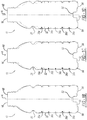
- Figure 1A illustrates the container 10 in an as-blown, pre-filled configuration.
- Figure 1B illustrates the container 10 after being hot-filled and subsequently cooled, with the as-blown position shown at AB.
- Figure 1C illustrates the container 10 subject to top load pressure, with the as-blown position shown at AB.
- Figure 1D illustrates the container 10 subject to additional top load pressure, with the as-blown position shown at AB.
- Figures 1B-1D are described further herein.
- the container 10 can be any suitable container for storing any suitable plurality of commodities, such as liquid beverages, food, or other hot-fill type materials.
- the container 10 can have any suitable shape or size, such as .592 liters (20 ounces) as illustrated.
- Any suitable material can be used to manufacture the container 10, such as a suitable blow-molded thermoplastic, including PET, LDPE, HDPE, PP, PS, and the like.
- the container 10 generally includes a finish 12 defining an opening 14 at a first or upper end 16 of the container 10.
- the finish 12 includes threads 18 at an outer surface thereof, which are configured to cooperate with a suitable closure for closing the opening 14. In addition to, or in place of, the threads 18, any suitable feature for cooperating with a closure to close the opening 14 can be included.
- the threads 18 are between the opening 14 and a support ring 20 of the finish 12.
- a neck portion 22 Extending from the support ring 20 on a side thereof opposite to the threads 18 is a neck portion 22.
- the neck portion 22 extends from the support ring 20 to a shoulder portion 24 of the container 10.
- the shoulder portion 24 tapers outward from the neck portion 22 in the direction of a main body portion 30.
- an inwardly tapered portion 26 Between the shoulder portion 24 and the main body portion 30 is an inwardly tapered portion 26.
- the inwardly tapered portion 26 provides the container 10 with a reduced diameter portion, which can be the smallest diameter portion of the container 10 to increase the strength of the container 10.
- the main body 30 extends to a second or lower end 40 of the container 10.
- the second or lower end 40 is at an end of the container 10 opposite to the first or upper end 16.
- a longitudinal axis A of the container 10 extends through an axial center of the container 10 between the first or upper end 16 and the second or lower end 40.
- the main body portion 30 includes a sidewall 32, which extends to a base portion 50 of the container 10.
- the sidewall 32 defines an internal volume 34 of the container 10 at an interior surface thereof.
- the sidewall 32 may be tapered inward towards the longitudinal axis A at one or more areas of the sidewall 32 in order to define recesses or ribs 36 at an exterior surface of the sidewall 32.
- the sidewall 32 defines five recesses or ribs 36a-36e.
- any suitable number of recesses or ribs 36 can be defined, or there may be no ribs at all, providing a smooth container side wall.
- the ribs 36 can have any suitable external diameter, which may vary amongst the different ribs 36.
- the first recess or rib 36a and the fourth recess or rib 36d can each have a diameter that is less than, and a height that is greater than, the second, third, and fifth recesses or ribs 36b, 36c, and 36e.
- the ribs 36 can articulate about the sidewall 32 to arrive at a vacuum absorbed position, as illustrated in Figure 1B for example.
- the ribs 36 can be vacuum ribs.
- the ribs 36 can also provide the container 10 with reinforcement features, thereby providing the container 10 with improved structural integrity and stability.
- the larger ribs 36a and 36d will have a greater vacuum response.
- Smaller ribs 36b, 36c, and 36e will provide the container with improved structural integrity.
- the base portion 50 generally includes a central push-up portion 52 at an axial center thereof, through which the longitudinal axis A extends.
- the central push-up portion 52 can be sized to stack with closures of a neighboring container 10, and also be sized to modify and optimize movement of the base portion 50 under vacuum.
- the diaphragm 54 can include any number of strengthening features defined therein.
- a plurality of first outer ribs 56a and a plurality of second outer ribs 56b can be defined in the diaphragm 54.
- the first and second outer ribs 56a and 56b extend radially with respect to the longitudinal axis A.
- the first outer ribs 56a extend entirely across the diaphragm 54.
- the second outer ribs 56b extend across less than an entirety of the diaphragm 54, such as across an outermost portion of the diameter 54.
- the first and the second outer ribs 56a and 56b can have any other suitable shape or configuration.
- the second outer ribs 56b can be replaced with additional first outer ribs 56a, which extend across the diaphragm 54.
- the first and second outer ribs 56a and 56b can be replaced with strengthening pads 92, which are spaced apart radially about the diaphragm 54. Any other suitable strengthening features can be included in the diaphragm 54, such as dimples, triangles, etc.
- the base portion 50 further includes a fold 60 at an outer diameter thereof.
- the fold 60 generally includes a first or inner folded portion 62 and a second or outer folded portion 64.
- the inner folded portion 62 includes a first or inner curved portion 66.
- the outer folded portion 64 includes a second or outer curved portion 68.
- the inner curved portion 66 has a curve radius R 1 and the outer curved portion 68 has a curve radius R 2 .
- the second or outer curved portion 68 extends to the sidewall 32.
- the outer folded portion 64, and specifically the outer curved portion 68 thereof, provide a heel of the base portion 50 and the container 10 as a whole.
- the intermediate portion 70 is generally linear, and generally extends parallel to the longitudinal axis A at least in the pre-fill configuration of the base portion 50 illustrated in Figure 4A .
- the intermediate portion 70 also extends generally parallel to the sidewall 32.
- a connecting portion 80 generally connects the inner folded portion 62 to the diaphragm 54.
- the connecting portion 80 includes a generally vertical portion 82 and a third curved portion 84.
- the generally vertical portion 82 extends from the inner folded portion 62 and specifically the inner curved portion 66 thereof.
- the generally vertical portion 82 extends generally parallel to the intermediate portion 70, the sidewall 32, and the longitudinal axis A of the container 10. In the pre-fill configuration of Figure 4A , the vertical portion 82 is spaced apart from the intermediate portion 70.
- the third curved portion 84 connects the vertical portion 82 to the diaphragm 54.
- the third curved portion 84 includes a curve radius R 3 .
- the fold 60 is arranged inward from the sidewall 32 at any suitable distance from the sidewall 32, such as 1-3 millimeters from the sidewall. Specifically, and with reference to Figures 4A and 4B , for example, distance F between the vertical portion 82 of the connecting portion 80 and the sidewall 32 can be 1-3 millimeters.
- the diaphragm 54 provides a standing surface of the base portion 50 and the overall container 10.
- the diaphragm 54 is at the second or lower end 40 of the container 10 and the outer folded portion 64 is arranged upward and spaced apart from the second or lower end 40.
- vacuum forces within the container 10 cause the diaphragm 54 to retract and move towards the first or upper end 16 until the diaphragm 54 is generally coplanar with the outer folded portion 64 at R3, or closer to the upper end 16 than the outer folded portion 64.
- the standing surface of the base 50 includes both the diaphragm 54 and the outer folded portion 64, or only the outer folded portion 64.
- the container 10 is supported on the standing surface by the diaphragm 54 of the base portion 50.
- the base portion 50 responds to the increase in internal vacuum and reduction of internal volume due to the cooling of the filled contents.
- the diaphragm 54 pivots around three hinge radius points R1, R2, and R3, and angles upwards into the container towards the first or upper end 16 from about zero degrees (0°) to about fifteen degrees (15°) at full activation, with a range of about ten degrees (10°) to twenty degrees (20°).
- Hinge radius R1 and hinge radius R2 are about the same dimension, while the hinge radius R3 is greater than R1 and R2.
- the primary hinge radius is R3, which changes in dimension to accommodate the movement of the diaphragm 54 described above and illustrated in Figure 4B .
- Radius R2 and radius R1 provide additional secondary dimensional change to adjust to the final shape of the base portion 50 under vacuum.
- radius R3 moves to about the same plane as radius R2, and radius R2 becomes the primary standing surface, as illustrated in Figure 4B for example.
- radii R1, R2, and R3 adjust to compensate for the movement of the diaphragm 54.
- the diaphragm 54 and radius R3 are about level with, or parallel to, the radius R2.
- the diaphragm 54, the radius R2, and the radius R3 are all generally level with, or parallel to, the standing surface and are constrained by the standing surface.
- vacuum base portion 50 and the horizontal ribs 36 allows the container 10 to reach a state of hydraulic charge up when a top load force is applied after the container 10 is filled, as illustrated in Figures 1C and 1D for example, which allows the container 10 to maintain its basic shape.
- This movement of the base portion 50 caused by top load force is constrained by the standing surface, and the horizontal ribs 36 begin to collapse, thereby causing filled internal fluid to approach an incompressible state. At this point the internal fluid resists further compression and the container 10 behaves similar to a hydraulic cylinder, while maintaining the basic shape of the container 10.
- Figure 7 is a graph of volume change versus pressure
- Figure 8 is a graph of filled, capped, and cooled top load versus displacement of an exemplary container 10 according to the present teachings. The various phases described herein are illustrated in Figures 6 and 7 .
- FIG. 1B With reference to Figure 1B , after the container is hot-filled and cooled, the base portion 50 is pulled up towards the upper end 16 due to internal vacuum. Overall height of the container 10 is reduced (compare the container 10 in the as-blown position AB), and the container 10 is supported upright at its outer folded portion 64, which is at radius R2, to provide the container 10 at phase 2.
- FIG 1C application of top load urges the base portion 50 to the original as-blown position of Figure 1A , and the internal vacuum crosses over to positive internal pressure, thereby providing phase 3.
- Figure 1D illustrates phase 4 and an increase in top load, which returns the base portion 50 substantially to the original as-blown position of Figure 1A and phase 1.
- the base portion 50 is constrained by the standing surface, the ribs 36 collapse causing further reduction in internal volume of the container 10, and a hydraulic spike in internal pressure advantageously facilitates very high top load capability.
- FIG. 5A-5C additional exemplary configurations of the base portion 50 are illustrated.
- the base portion 50 is illustrated in the as blown, pre-fill configuration with the diaphragm 54 generally coplanar with the outer folded portion 64 such that both the diaphragm 54 and the outer folded portion 64 provide the container 10 with a pre-fill standing surface.
- the diaphragm 54 retracts towards the first or upper end 16 such that the outer folded portion 64 solely provides the post-fill standing surface of the container 10.
- Figure 5B illustrates the base 50 in the pre-fill configuration, and is similar to the configuration of Figure 5A , but the connecting portion 80 further includes an inset portion 90.
- the inset portion 90 is between the third curved portion 84 of the connecting portion 80 and the diaphragm 54.
- Figure 5C illustrates the base portion 50 again in the pre-fill configuration.
- the pre-fill configuration illustrated in 5C is similar to that illustrated in Figure 5A , but the outer folded portion 64 is closer to the first or upper end 16 of the container 10 as compared to the configuration of Figure 5A .
- the outer folded portion 64 of Figure 5C is closer to the fifth recess or rib 36e as compared to the outer folded portion 64 illustrated in Figure 5A .
- the vertical portion 82 of the connecting portion 80 has an increased length.
- a heel portion of existing containers can often become deformed upon being subject to approximately 67.7 N (15.38 pounds) of side load force at a compressive extension of about 6.35 mm (0.250").
- an exemplary container according to the present teachings was found to not experience deformation at the fold 60 (which generally replaces a heal of a conventional container) until being subject to about 96.7 N (21.97 pounds) of side load force at a compressive extension of 6.35 mm (0.250").
- Figure 8 shows an example of the side load force test.
- the fold 60 can be formed in any suitable manner.
- the fold 60 can be formed by an overstroke of 1-10 millimeters, which is advantageously smaller than overstroke procedures for forming existing containers. Reducing the overstroke provides for increased cycle time and a more repeatable manufacturing process.
- the fold 60 can be formed without individual cavity operator adjustment, which increases consistency of the blow molding process.
- Most container designs that employ overstroke have a container standing surface that resides below the active portion of the assigned vacuum absorbing base technology, which is in contrast to the container 10 in which the standing surface is within the vacuum absorbing zone.
- the fold 60 also advantageously provides the base portion 50 with an increased vacuum displacement area, such as in the range of 90-95 percent of the entire base portion 50. Because the pre-fill standing surface of the base portion 50 is within the vacuum absorbing zone, any vacuum related shape change improves filled capped topload result by way of a charge-up scenario known to those skilled in the art of hot-fill package design in which fluid within the container 10 reaches an incompressible hydraulic state. This provides for self-correction of any minor sidewall imperfections experienced during fill line/warehouse handling.
- the fold 60 is advantageously stronger than the sidewall 32.
- the fold 60 is about 2-6 times stronger than the sidewall 32.
- the fold 60 can be included with sidewalls 32 of various thicknesses, such as 0.1-0.5 millimeters.
- the strength of the fold 60 is independent of the thickness of the sidewall 32.
- the thickness of the sidewall 32 can be reduced in order to reduce the overall weight of the container 10 without sacrificing strength in the base portion 50.
- the sidewall 32 can have a thickness of less than 0.4 millimeters, which advantageously reduces the overall weight of the container 10.
- the fold 60 is located in a non-critical handling zone. Therefore, minor imperfections, such as flash, incomplete forming, or denting, will not negatively affect the height or handling of the container 10, which can reduce scrap in the manufacturing process.
- Example embodiments are provided so that this disclosure will be thorough, and will fully convey the scope to those who are skilled in the art. Numerous specific details are set forth such as examples of specific components, devices, and methods, to provide a thorough understanding of embodiments of the present disclosure. It will be apparent to those skilled in the art that specific details need not be employed, that example embodiments may be embodied in many different forms and that neither should be construed to limit the scope of the disclosure. In some example embodiments, well-known processes, well-known device structures, and well-known technologies are not described in detail.
- first, second, third, etc. may be used herein to describe various elements, components, regions, layers and/or sections, these elements, components, regions, layers and/or sections should not be limited by these terms. These terms may be only used to distinguish one element, component, region, layer or section from another region, layer or section. Terms such as “first,” “second,” and other numerical terms when used herein do not imply a sequence or order unless clearly indicated by the context. Thus, a first element, component, region, layer or section discussed below could be termed a second element, component, region, layer or section without departing from the teachings of the example embodiments.
- spatially relative terms such as “inner,” “outer,” “beneath,” “below,” “lower,” “above,” “upper,” and the like, may be used herein for ease of description to describe one element or feature's relationship to another element(s) or feature(s) as illustrated in the figures.
- Spatially relative terms may be intended to encompass different orientations of the device in use or operation in addition to the orientation depicted in the figures. For example, if the device in the figures is turned over, elements described as “below” or “beneath” other elements or features would then be oriented “above” the other elements or features.
- the example term “below” can encompass both an orientation of above and below.
- the device may be otherwise oriented (rotated 90 degrees or at other orientations) and the spatially relative descriptors used herein interpreted accordingly.
Landscapes
- Engineering & Computer Science (AREA)
- Mechanical Engineering (AREA)
- Ceramic Engineering (AREA)
- Containers Having Bodies Formed In One Piece (AREA)
- Blow-Moulding Or Thermoforming Of Plastics Or The Like (AREA)
- Packages (AREA)
Description
- The present disclosure relates to a container with a folded sidewall according to the preamble of claim 1. Such a container is known from
US 2012/0037645 A1 . Similar containers having a folded sidewall are known fromUS 2013/0240477 A1 , fromUS 2014/0123603 A1 , and fromUS 2013/0220968 A1 . - This section provides background information related to the present disclosure, which is not necessarily prior art.
- As a result of environmental and other concerns, plastic containers, more specifically polyester and even more specifically polyethylene terephthalate (PET) containers, are now being used more than ever to package numerous commodities previously supplied in glass containers. Manufacturers and fillers, as well as consumers, have recognized that PET containers are lightweight, inexpensive, recyclable and manufacturable in large quantities.
- Blow-molded plastic containers have become commonplace in packaging numerous commodities. PET is a crystallizable polymer, meaning that it is available in an amorphous form or a semi-crystalline form. The ability of a PET container to maintain its material integrity relates to the percentage of the PET container in crystalline form, also known as the "crystallinity" of the PET container. The following equation defines the percentage of crystallinity as a volume fraction:

- Container manufacturers use mechanical processing and thermal processing to increase the PET polymer crystallinity of a container. Mechanical processing involves orienting the amorphous material to achieve strain hardening. This processing commonly involves stretching an injection molded PET preform along a longitudinal axis and expanding the PET preform along a transverse or radial axis to form a PET container. The combination promotes what manufacturers define as biaxial orientation of the molecular structure in the container. Manufacturers of PET containers currently use mechanical processing to produce PET containers having approximately 20% crystallinity in the container's sidewall.
- Thermal processing involves heating the material (either amorphous or semi-crystalline) to promote crystal growth. On amorphous material, thermal processing of PET material results in a spherulitic morphology that interferes with the transmission of light. In other words, the resulting crystalline material is opaque, and thus, generally undesirable. Used after mechanical processing, however, thermal processing results in higher crystallinity and excellent clarity for those portions of the container having biaxial molecular orientation. The thermal processing of an oriented PET container, which is known as heat setting, typically includes blow molding a PET preform against a mold heated to a temperature of approximately 250°F - 350°F (approximately 121°C - 177°C), and holding the blown container against the heated mold for approximately two (2) to five (5) seconds. Manufacturers of PET juice bottles, which must be hot-filled at approximately 185°F (85°C), currently use heat setting to produce PET bottles having an overall crystallinity in the range of approximately 25%-35%.
- While current containers are suitable for their intended use, they are subject to improvement. For example, a container having reduced weight and increased strength would be desirable.
- This section provides a general summary of the disclosure, and is not a comprehensive disclosure of its full scope or all of its features,
- The container known from
US 2012/0037645 A1 mentioned at the outset does provide some improvement with respect to an adjustment capability of the container to varying internal pressures. However, still further improvement is needed. - In view of this it is an object of the invention to disclose an improved container that provides for better adjustment of the container to varying internal pressures.
- This object is achieved by a container according to claim 1. Preferred embodiments are subject of the dependent claims.
- The present teachings provide for a blow-molded container having a base portion that effectively absorbs internal vacuum while maintaining basic shape, and resists deforming under top load. The finish defines an opening at a first end of the container that provides access to an internal volume defined by the container. The base portion is at a second end of the container opposite to the first end. The base portion includes a fold proximate to a sidewall of the container.
- The present teachings further provide for a blow-molded container including a finish and a base portion. The finish defines an opening at a first end of the container that provides access to an internal volume defined by the container. The base portion is at a second end of the container opposite to the first end. The base portion includes a fold having an outer fold portion at a sidewall of the container, and an inner fold portion that is inward of the outer fold portion. The inner fold portion is closer to the first end than the outer fold portion is.
- The present teachings provide for another blow-molded container including a finish and a base portion. The finish defines an opening at a first end of the container that provides access to an internal volume defined by the container. The base portion is at a second end of the container opposite to the first end. The base portion includes a fold, a diaphragm, and a connecting portion. The fold has an inner folded portion including a first curve and an outer folded portion at a sidewall of the container including a second curve. The inner folded portion is closer to the first end of the container than the outer folded portion. The outer folded portion may provide a post-fill standing surface of the container. The diaphragm extends between the fold and an axial center of the container. The diaphragm may provide a pre-filled standing surface of the container. The connecting portion is between the inner folded portion and the diaphragm, and includes a third curve.
- Further areas of applicability will become apparent from the description provided herein. The description and specific examples in this summary are intended for purposes of illustration only and are not intended to limit the scope of the present disclosure.
- The drawings described herein are for illustrative purposes only of selected embodiments and not all possible implementations, and are not intended to limit the scope of the present disclosure.
-
Figure 1A is a side view of a container according to the present teachings in an as-blown, pre-filled configuration; -
Figure 1B is a side view of the container ofFigure 1A after the container has been hot-filled and has cooled; -
Figure 1C is a side view of the filled container ofFigure 1B subject to a top load pressure; -
Figure 1D is a side view of the container ofFigure 1C subject to further top load pressure; -
Figure 2A is a perspective view of a base portion of the container ofFigure 1 ; -
Figure 2B is a planar view of a base portion of another container according to the present teachings; -
Figure 2C is a planar view of a base portion of yet another container according to the present teachings; -
Figure 3 is a cross-sectional view taken along line 3-3 ofFigure 2A ; -
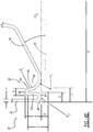
Figure 4A is a schematic view of an area of the base portion of the container ofFigure 1 in a pre-fill configuration, the base portion including a fold; -
Figure 4B is a schematic view of the area of the base portion of the container ofFigure 1 in a post-fill configuration; -
Figure 5A is a schematic view of another container base portion according to the present teachings illustrating the base portion in a pre-fill configuration; -
Figure 5B is a schematic view of an additional container base portion according to the present teachings illustrating the base portion in a pre-fill configuration; -
Figure 5C is a schematic view of still another container base portion according to the present teachings illustrating the base portion in a pre-fill configuration; -
Figure 6 is a graph illustrating volume change versus pressure of an exemplary container according to the present teachings; -
Figure 7 is a graph of filled, capped, and cooled top load versus displacement of an exemplary container according to the present teachings; and -
Figure 8 illustrates a heel denting/side load force test. - Corresponding reference numerals indicate corresponding parts throughout the several views of the drawings.
- Example embodiments will now be described more fully with reference to the accompanying drawings.
- With initial reference to
Figure 1A , a container according to the present teachings is generally illustrated atreference numeral 10.Figure 1A illustrates thecontainer 10 in an as-blown, pre-filled configuration.Figure 1B illustrates thecontainer 10 after being hot-filled and subsequently cooled, with the as-blown position shown at AB.Figure 1C illustrates thecontainer 10 subject to top load pressure, with the as-blown position shown at AB.Figure 1D illustrates thecontainer 10 subject to additional top load pressure, with the as-blown position shown at AB.Figures 1B-1D are described further herein. - As illustrated in
Figure 1A , thecontainer 10 can be any suitable container for storing any suitable plurality of commodities, such as liquid beverages, food, or other hot-fill type materials. Thecontainer 10 can have any suitable shape or size, such as .592 liters (20 ounces) as illustrated. Any suitable material can be used to manufacture thecontainer 10, such as a suitable blow-molded thermoplastic, including PET, LDPE, HDPE, PP, PS, and the like. - The
container 10 generally includes afinish 12 defining anopening 14 at a first orupper end 16 of thecontainer 10. Thefinish 12 includesthreads 18 at an outer surface thereof, which are configured to cooperate with a suitable closure for closing theopening 14. In addition to, or in place of, thethreads 18, any suitable feature for cooperating with a closure to close theopening 14 can be included. Thethreads 18 are between theopening 14 and asupport ring 20 of thefinish 12. - Extending from the
support ring 20 on a side thereof opposite to thethreads 18 is aneck portion 22. Theneck portion 22 extends from thesupport ring 20 to ashoulder portion 24 of thecontainer 10. Theshoulder portion 24 tapers outward from theneck portion 22 in the direction of amain body portion 30. Between theshoulder portion 24 and themain body portion 30 is an inwardly taperedportion 26. The inwardly taperedportion 26 provides thecontainer 10 with a reduced diameter portion, which can be the smallest diameter portion of thecontainer 10 to increase the strength of thecontainer 10. - The
main body 30 extends to a second orlower end 40 of thecontainer 10. The second orlower end 40 is at an end of thecontainer 10 opposite to the first orupper end 16. A longitudinal axis A of thecontainer 10 extends through an axial center of thecontainer 10 between the first orupper end 16 and the second orlower end 40. - The
main body portion 30 includes asidewall 32, which extends to abase portion 50 of thecontainer 10. Thesidewall 32 defines aninternal volume 34 of thecontainer 10 at an interior surface thereof. Thesidewall 32 may be tapered inward towards the longitudinal axis A at one or more areas of thesidewall 32 in order to define recesses or ribs 36 at an exterior surface of thesidewall 32. As illustrated, thesidewall 32 defines five recesses orribs 36a-36e. However, any suitable number of recesses or ribs 36 can be defined, or there may be no ribs at all, providing a smooth container side wall. The ribs 36 can have any suitable external diameter, which may vary amongst the different ribs 36. For example and as illustrated, the first recess orrib 36a and the fourth recess orrib 36d can each have a diameter that is less than, and a height that is greater than, the second, third, and fifth recesses orribs sidewall 32 to arrive at a vacuum absorbed position, as illustrated inFigure 1B for example. Thus, the ribs 36 can be vacuum ribs. The ribs 36 can also provide thecontainer 10 with reinforcement features, thereby providing thecontainer 10 with improved structural integrity and stability. Thelarger ribs Smaller ribs - The
base portion 50 generally includes a central push-upportion 52 at an axial center thereof, through which the longitudinal axis A extends. The central push-upportion 52 can be sized to stack with closures of a neighboringcontainer 10, and also be sized to modify and optimize movement of thebase portion 50 under vacuum. - Surrounding the central push-up
portion 52 is adiaphragm 54. Thediaphragm 54 can include any number of strengthening features defined therein. For example and as illustrated inFigure 2A , a plurality of firstouter ribs 56a and a plurality of second outer ribs 56b can be defined in thediaphragm 54. The first and secondouter ribs 56a and 56b extend radially with respect to the longitudinal axis A. The firstouter ribs 56a extend entirely across thediaphragm 54. The second outer ribs 56b extend across less than an entirety of thediaphragm 54, such as across an outermost portion of thediameter 54. The first and the secondouter ribs 56a and 56b can have any other suitable shape or configuration. For example and as illustrated inFigure 2B , the second outer ribs 56b can be replaced with additional firstouter ribs 56a, which extend across thediaphragm 54. With reference toFigure 2C , the first and secondouter ribs 56a and 56b can be replaced with strengtheningpads 92, which are spaced apart radially about thediaphragm 54. Any other suitable strengthening features can be included in thediaphragm 54, such as dimples, triangles, etc. - The
base portion 50 further includes afold 60 at an outer diameter thereof. With continued reference toFigures 1A and2A-2C , and additional reference toFigures 3 ,4a (pre-fill, as-blown configuration), and 4b (post-fill configuration), thefold 60 generally includes a first or inner foldedportion 62 and a second or outer foldedportion 64. The inner foldedportion 62 includes a first or innercurved portion 66. The outer foldedportion 64 includes a second or outer curved portion 68. The innercurved portion 66 has a curve radius R1 and the outer curved portion 68 has a curve radius R2. The second or outer curved portion 68 extends to thesidewall 32. The outer foldedportion 64, and specifically the outer curved portion 68 thereof, provide a heel of thebase portion 50 and thecontainer 10 as a whole. - Between the inner
curved portion 66 and the outer curved portion 68 is anintermediate portion 70 of thefold 60. Theintermediate portion 70 is generally linear, and generally extends parallel to the longitudinal axis A at least in the pre-fill configuration of thebase portion 50 illustrated inFigure 4A . Theintermediate portion 70 also extends generally parallel to thesidewall 32. - A connecting
portion 80 generally connects the inner foldedportion 62 to thediaphragm 54. The connectingportion 80 includes a generallyvertical portion 82 and a thirdcurved portion 84. The generallyvertical portion 82 extends from the inner foldedportion 62 and specifically the innercurved portion 66 thereof. The generallyvertical portion 82 extends generally parallel to theintermediate portion 70, thesidewall 32, and the longitudinal axis A of thecontainer 10. In the pre-fill configuration ofFigure 4A , thevertical portion 82 is spaced apart from theintermediate portion 70. In the example ofFigures 4A and4B , the thirdcurved portion 84 connects thevertical portion 82 to thediaphragm 54. The thirdcurved portion 84 includes a curve radius R3. Thefold 60 is arranged inward from thesidewall 32 at any suitable distance from thesidewall 32, such as 1-3 millimeters from the sidewall. Specifically, and with reference toFigures 4A and4B , for example, distance F between thevertical portion 82 of the connectingportion 80 and thesidewall 32 can be 1-3 millimeters. - In the pre-fill configuration of
Figure 4A , thediaphragm 54 provides a standing surface of thebase portion 50 and theoverall container 10. Thus thediaphragm 54 is at the second orlower end 40 of thecontainer 10 and the outer foldedportion 64 is arranged upward and spaced apart from the second orlower end 40. With additional reference toFigure 4B , after thecontainer 10 is filled, such as by way of a hot-fill process, vacuum forces within thecontainer 10 cause thediaphragm 54 to retract and move towards the first orupper end 16 until thediaphragm 54 is generally coplanar with the outer foldedportion 64 at R3, or closer to theupper end 16 than the outer foldedportion 64. Thus in the post-fill configuration ofFigure 4B , the standing surface of thebase 50 includes both thediaphragm 54 and the outer foldedportion 64, or only the outer foldedportion 64. - In the pre-fill configuration of
Figure 4A , thecontainer 10 is supported on the standing surface by thediaphragm 54 of thebase portion 50. After hot-filling and capping, thebase portion 50 responds to the increase in internal vacuum and reduction of internal volume due to the cooling of the filled contents. As illustrated inFigure 4B for example, thediaphragm 54 pivots around three hinge radius points R1, R2, and R3, and angles upwards into the container towards the first orupper end 16 from about zero degrees (0°) to about fifteen degrees (15°) at full activation, with a range of about ten degrees (10°) to twenty degrees (20°). - Hinge radius R1 and hinge radius R2 are about the same dimension, while the hinge radius R3 is greater than R1 and R2. The primary hinge radius is R3, which changes in dimension to accommodate the movement of the
diaphragm 54 described above and illustrated inFigure 4B . Radius R2 and radius R1 provide additional secondary dimensional change to adjust to the final shape of thebase portion 50 under vacuum. Upon full activation, radius R3 moves to about the same plane as radius R2, and radius R2 becomes the primary standing surface, as illustrated inFigure 4B for example. When a top load force is applied, the angle of thediaphragm 54 is urged back to 0°, and radii R1, R2, and R3 adjust to compensate for the movement of thediaphragm 54. Under top load, thediaphragm 54 and radius R3 are about level with, or parallel to, the radius R2. Thediaphragm 54, the radius R2, and the radius R3 are all generally level with, or parallel to, the standing surface and are constrained by the standing surface. - The combination of
vacuum base portion 50 and the horizontal ribs 36 allows thecontainer 10 to reach a state of hydraulic charge up when a top load force is applied after thecontainer 10 is filled, as illustrated inFigures 1C and 1D for example, which allows thecontainer 10 to maintain its basic shape. This movement of thebase portion 50 caused by top load force is constrained by the standing surface, and the horizontal ribs 36 begin to collapse, thereby causing filled internal fluid to approach an incompressible state. At this point the internal fluid resists further compression and thecontainer 10 behaves similar to a hydraulic cylinder, while maintaining the basic shape of thecontainer 10. - More specifically, in the as-blown, prefilled configuration AB of
Figure 1A , thecontainer 10 stands upright while resting on thediaphragm 54, and volume and pressure are zero or generally zero, thereby providing thecontainer 10 in phase 1.Figure 7 is a graph of volume change versus pressure, andFigure 8 is a graph of filled, capped, and cooled top load versus displacement of anexemplary container 10 according to the present teachings. The various phases described herein are illustrated inFigures 6 and7 . - With reference to
Figure 1B , after the container is hot-filled and cooled, thebase portion 50 is pulled up towards theupper end 16 due to internal vacuum. Overall height of thecontainer 10 is reduced (compare thecontainer 10 in the as-blown position AB), and thecontainer 10 is supported upright at its outer foldedportion 64, which is at radius R2, to provide thecontainer 10 atphase 2. With reference toFigure 1C , application of top load urges thebase portion 50 to the original as-blown position ofFigure 1A , and the internal vacuum crosses over to positive internal pressure, thereby providingphase 3.Figure 1D illustratesphase 4 and an increase in top load, which returns thebase portion 50 substantially to the original as-blown position ofFigure 1A and phase 1. Thebase portion 50 is constrained by the standing surface, the ribs 36 collapse causing further reduction in internal volume of thecontainer 10, and a hydraulic spike in internal pressure advantageously facilitates very high top load capability. - With additional reference to
Figures 5A-5C , additional exemplary configurations of thebase portion 50 are illustrated. With initial reference toFigure 5A , thebase portion 50 is illustrated in the as blown, pre-fill configuration with thediaphragm 54 generally coplanar with the outer foldedportion 64 such that both thediaphragm 54 and the outer foldedportion 64 provide thecontainer 10 with a pre-fill standing surface. After thecontainer 10 is filled, such as by hot filling, thediaphragm 54 retracts towards the first orupper end 16 such that the outer foldedportion 64 solely provides the post-fill standing surface of thecontainer 10. -
Figure 5B illustrates the base 50 in the pre-fill configuration, and is similar to the configuration ofFigure 5A , but the connectingportion 80 further includes aninset portion 90. Theinset portion 90 is between the thirdcurved portion 84 of the connectingportion 80 and thediaphragm 54.Figure 5C illustrates thebase portion 50 again in the pre-fill configuration. The pre-fill configuration illustrated in 5C is similar to that illustrated inFigure 5A , but the outer foldedportion 64 is closer to the first orupper end 16 of thecontainer 10 as compared to the configuration ofFigure 5A . For example, the outer foldedportion 64 ofFigure 5C is closer to the fifth recess orrib 36e as compared to the outer foldedportion 64 illustrated inFigure 5A . To compensate for the outer foldedportion 64 ofFigure 5C being closer to the first orupper end 16, thevertical portion 82 of the connectingportion 80 has an increased length. - The advantages of the
container 10 according to the present teachings as compared to existing containers are as follows: For example, a heel portion of existing containers (generally located at an outer rim or wall of a base thereof) can often become deformed upon being subject to approximately 67.7 N (15.38 pounds) of side load force at a compressive extension of about 6.35 mm (0.250"). In contrast, an exemplary container according to the present teachings was found to not experience deformation at the fold 60 (which generally replaces a heal of a conventional container) until being subject to about 96.7 N (21.97 pounds) of side load force at a compressive extension of 6.35 mm (0.250").Figure 8 shows an example of the side load force test. - The
fold 60 can be formed in any suitable manner. For example, thefold 60 can be formed by an overstroke of 1-10 millimeters, which is advantageously smaller than overstroke procedures for forming existing containers. Reducing the overstroke provides for increased cycle time and a more repeatable manufacturing process. For example, thefold 60 can be formed without individual cavity operator adjustment, which increases consistency of the blow molding process. Most container designs that employ overstroke have a container standing surface that resides below the active portion of the assigned vacuum absorbing base technology, which is in contrast to thecontainer 10 in which the standing surface is within the vacuum absorbing zone. - The
fold 60 also advantageously provides thebase portion 50 with an increased vacuum displacement area, such as in the range of 90-95 percent of theentire base portion 50. Because the pre-fill standing surface of thebase portion 50 is within the vacuum absorbing zone, any vacuum related shape change improves filled capped topload result by way of a charge-up scenario known to those skilled in the art of hot-fill package design in which fluid within thecontainer 10 reaches an incompressible hydraulic state. This provides for self-correction of any minor sidewall imperfections experienced during fill line/warehouse handling. - The
fold 60 is advantageously stronger than thesidewall 32. For example, thefold 60 is about 2-6 times stronger than thesidewall 32. Thefold 60 can be included withsidewalls 32 of various thicknesses, such as 0.1-0.5 millimeters. The strength of thefold 60 is independent of the thickness of thesidewall 32. Thus the thickness of thesidewall 32 can be reduced in order to reduce the overall weight of thecontainer 10 without sacrificing strength in thebase portion 50. For example, thesidewall 32 can have a thickness of less than 0.4 millimeters, which advantageously reduces the overall weight of thecontainer 10. - The
fold 60 is located in a non-critical handling zone. Therefore, minor imperfections, such as flash, incomplete forming, or denting, will not negatively affect the height or handling of thecontainer 10, which can reduce scrap in the manufacturing process. - The foregoing description of the embodiments has been provided for purposes of illustration and description. It is not intended to be exhaustive or to limit the disclosure. Individual elements or features of a particular embodiment are generally not limited to that particular embodiment, but, where applicable, are interchangeable and can be used in a selected embodiment, even if not specifically shown or described. The same may also be varied in many ways. Such variations are not to be regarded as a departure from the disclosure, and all such modifications are intended to be included within the scope of the disclosure.
- Example embodiments are provided so that this disclosure will be thorough, and will fully convey the scope to those who are skilled in the art. Numerous specific details are set forth such as examples of specific components, devices, and methods, to provide a thorough understanding of embodiments of the present disclosure. It will be apparent to those skilled in the art that specific details need not be employed, that example embodiments may be embodied in many different forms and that neither should be construed to limit the scope of the disclosure. In some example embodiments, well-known processes, well-known device structures, and well-known technologies are not described in detail.
- The terminology used herein is for the purpose of describing particular example embodiments only and is not intended to be limiting. As used herein, the singular forms "a," "an," and "the" may be intended to include the plural forms as well, unless the context clearly indicates otherwise. The terms "comprises," "comprising," "including," and "having," are inclusive and therefore specify the presence of stated features, integers, steps, operations, elements, and/or components, but do not preclude the presence or addition of one or more other features, integers, steps, operations, elements, components, and/or groups thereof. The method steps, processes, and operations described herein are not to be construed as necessarily requiring their performance in the particular order discussed or illustrated, unless specifically identified as an order of performance. It is also to be understood that additional or alternative steps may be employed.
- When an element or layer is referred to as being "on," "engaged to," "connected to," or "coupled to" another element or layer, it may be directly on, engaged, connected or coupled to the other element or layer, or intervening elements or layers may be present. In contrast, when an element is referred to as being "directly on," "directly engaged to," "directly connected to," or "directly coupled to" another element or layer, there may be no intervening elements or layers present. Other words used to describe the relationship between elements should be interpreted in a like fashion (e.g., "between" versus "directly between," "adjacent" versus "directly adjacent," etc.). As used herein, the term "and/or" includes any and all combinations of one or more of the associated listed items.
- Although the terms first, second, third, etc. may be used herein to describe various elements, components, regions, layers and/or sections, these elements, components, regions, layers and/or sections should not be limited by these terms. These terms may be only used to distinguish one element, component, region, layer or section from another region, layer or section. Terms such as "first," "second," and other numerical terms when used herein do not imply a sequence or order unless clearly indicated by the context. Thus, a first element, component, region, layer or section discussed below could be termed a second element, component, region, layer or section without departing from the teachings of the example embodiments.
- Spatially relative terms, such as "inner," "outer," "beneath," "below," "lower," "above," "upper," and the like, may be used herein for ease of description to describe one element or feature's relationship to another element(s) or feature(s) as illustrated in the figures. Spatially relative terms may be intended to encompass different orientations of the device in use or operation in addition to the orientation depicted in the figures. For example, if the device in the figures is turned over, elements described as "below" or "beneath" other elements or features would then be oriented "above" the other elements or features. Thus, the example term "below" can encompass both an orientation of above and below. The device may be otherwise oriented (rotated 90 degrees or at other orientations) and the spatially relative descriptors used herein interpreted accordingly.
Claims (15)
- A blow-molded container comprising:a finish (12) defining an opening (14) at a first end (16) of the container (10) that provides access to an internal volume defined by the container (10); anda base portion (50) at a second end (40) of the container (10) opposite to the first end (16), the base portion (50) including a fold (60) having an outer folded portion (64) proximate to a sidewall (32) of the container (10), and an inner folded portion (62) that is inward of the outer folded portion (64), the inner folded portion (62) being closer to the first end (16) than the outer folded portion (64);wherein as blown and prior to the container (10) being filled, a diaphragm (54) of the base portion (50) is further from the first end (16) of the container (10) than the outer folded portion (64);wherein after the container (10) is filled, the diaphragm (54) is not further from the first end (16) of the container (10) than the outer folded portion (64);characterized in that the diaphragm (54) pivots about a first radius (R1) at an inner curved portion (66) of the fold (60), a second radius (R2) at an outer curved portion (68) of the fold (60), and a third radius (R3) between the diaphragm (54) and the first radius (R1).
- The blow-molded container of Claim 1, further comprising an intermediate portion (70) of the fold (60) between the outer folded portion (64) and the inner folded portion (62), wherein the intermediate portion (70) has a first length before the container (10) is filled and a second length after the container (10) is filled, the first length is shorter than the second length.
- The blow-molded container of Claim 2, further comprising a connecting portion (80) between the inner folded portion (62) and the diaphragm (54), the connecting portion (80) including a generally vertical portion (82) that is generally parallel to a longitudinal axis (A) of the container (10) and a curved portion (84) between the generally vertical portion (82) and the diaphragm (54).
- The blow-molded container of Claim 3, wherein the generally vertical portion (82) of the connecting portion (80) and the intermediate portion (70) between the outer folded portion (64) and the inner folded portion (62) are spaced apart at a pre-fill distance prior to the container (10) being filled, and closer together than the pre-fill distance after the container (10) is filled.
- The blow-molded container of Claim 1, wherein the base portion (50) includes the diaphragm (54) that provides a pre-fill standing surface of the container (10), subsequent to the container (10) being filled, the diaphragm (54) is configured to move closer to the first end (16) of the container (10) and the outer curved portion (68) provides a post-fill standing surface.
- The blow-molded container of Claim 1, wherein the inner folded portion (62) includes an inner curved portion (66) and the outer folded portion (64) includes an outer curved portion (68), the inner curved portion (66) is closer to the first end (16) than the outer curved portion (68).
- The blow-molded container of claim 1,
wherein the diaphragm (54) provides a pre-fill standing surface of the container (10). - The container of Claim 1, wherein after the container (10) is filled, the diaphragm (54) angles towards the finish (12) between 0° and 15° at full activation.
- The container of Claim 1, wherein after the container (10) is filled, the diaphragm (54) angles towards the finish (12) between 10° and 20° at full activation.
- The container of Claim 1, wherein the first radius (R1) and the second radius (R2) are about the same dimension and the third radius (R3) is greater than each of the first radius (R1) and the second radius (R2).
- The container of claim 1, wherein the third radius (R3) and the second radius (R2) both provide a post-fill standing surface of the container (10).
- The container of Claim 1, wherein upon application of a top load force to the container (10), the angle of the diaphragm (54) returns to 0° relative to the first end (16), and the first, second, and third radii (R1, R2, R3) adjust to compensate for such movement of the diaphragm (54).
- The container of Claim 1, wherein the container (10) further comprises a plurality of ribs (56a, b) defined in a sidewall (32) of the container (10).
- The container of claim 1, wherein the plurality of ribs (56a, b) and the base portion (15) are configured to place the container (10) in a state of hydraulic chargeup when top load is applied to the container (10) after the container (10) is filled.
- The container of claim 14, wherein the plurality of ribs (56a, b) collapse upon application of top load, and movement of the base portion (50) is constrained by a standing surface, thereby causing fluid within an internal volume of the container (10) to reach an incompressible state to maintain the container (10) at its same basic shape.
Applications Claiming Priority (1)
| Application Number | Priority Date | Filing Date | Title |
|---|---|---|---|
| PCT/US2014/052148 WO2016028302A1 (en) | 2014-08-21 | 2014-08-21 | Container with folded sidewall |
Publications (3)
| Publication Number | Publication Date |
|---|---|
| EP3183180A1 EP3183180A1 (en) | 2017-06-28 |
| EP3183180A4 EP3183180A4 (en) | 2018-03-21 |
| EP3183180B1 true EP3183180B1 (en) | 2020-06-24 |
Family
ID=55351087
Family Applications (1)
| Application Number | Title | Priority Date | Filing Date |
|---|---|---|---|
| EP14900267.7A Active EP3183180B1 (en) | 2014-08-21 | 2014-08-21 | Container with folded sidewall |
Country Status (8)
| Country | Link |
|---|---|
| US (1) | US9994351B2 (en) |
| EP (1) | EP3183180B1 (en) |
| BR (1) | BR112017003569B1 (en) |
| CA (1) | CA2957823C (en) |
| CO (1) | CO2017001873A2 (en) |
| ES (1) | ES2806554T3 (en) |
| MX (1) | MX382105B (en) |
| WO (1) | WO2016028302A1 (en) |
Families Citing this family (11)
| Publication number | Priority date | Publication date | Assignee | Title |
|---|---|---|---|---|
| US10538357B2 (en) | 2011-08-31 | 2020-01-21 | Amcor Rigid Plastics Usa, Llc | Lightweight container base |
| MX2018006866A (en) | 2015-12-07 | 2018-09-06 | Amcor Group Gmbh | UPPER LOAD FORCE APPLICATION METHOD |
| PE20200067A1 (en) * | 2017-04-28 | 2020-01-15 | Amcor Rigid Plastics Usa Llc | LIGHTWEIGHT CONTAINER BASE |
| USD859992S1 (en) * | 2017-09-12 | 2019-09-17 | The Coca-Cola Company | Bottle |
| FR3076818B1 (en) * | 2018-01-18 | 2019-12-13 | Sidel Participations | CONTAINER COMPRISING A VOUTE BOTTOM HAVING RIGIDIFICATION BOSSES DISTRIBUTED IN NESTED ANNULAR STRIPS |
| MX2020011255A (en) * | 2018-04-26 | 2020-11-12 | Graham Packaging Co | Pressurized refill container resistant to standing ring cracking. |
| JP7370248B2 (en) * | 2019-12-27 | 2023-10-27 | 株式会社吉野工業所 | Bottle |
| AU2021202920A1 (en) * | 2020-05-08 | 2021-11-25 | Orora Packaging Australia Pty Ltd | A bottle, and an insert and a mould for making the bottle |
| CA222024S (en) * | 2022-12-09 | 2024-12-19 | David Melrose Design Ltd | Container |
| WO2026009103A1 (en) * | 2024-07-05 | 2026-01-08 | Co2Pac Limited | Multi-spring hinge base for plastic bottles |
| USD1126002S1 (en) | 2024-10-08 | 2026-05-12 | Co2Pac Limited | Container |
Family Cites Families (23)
| Publication number | Priority date | Publication date | Assignee | Title |
|---|---|---|---|---|
| US2339763A (en) * | 1941-03-21 | 1944-01-25 | Crown Cork & Seal Co | Container and method of making same |
| US3870181A (en) * | 1973-02-12 | 1975-03-11 | Monsanto Co | Molecularly oriented bottle |
| US4082200A (en) | 1976-06-29 | 1978-04-04 | Owens-Illinois, Inc. | Plastic container with support base, and method of assembly |
| SE430148B (en) * | 1979-05-11 | 1983-10-24 | Plm Ab | CONTAINERS CONSISTING OF A PLASTIC MATERIAL BODY WITH A CONVEX BOTTOM PART AND OF A STATION SOCKET FOR SUPPORTING THE CONTAINER BODY |
| US4342398A (en) * | 1980-10-16 | 1982-08-03 | Owens-Illinois, Inc. | Self-supporting plastic container for liquids |
| US4863046A (en) | 1987-12-24 | 1989-09-05 | Continental Pet Technologies, Inc. | Hot fill container |
| US4836398A (en) * | 1988-01-29 | 1989-06-06 | Aluminum Company Of America | Inwardly reformable endwall for a container |
| JP2000128140A (en) | 1998-10-20 | 2000-05-09 | Aoki Technical Laboratory Inc | Heat resistant packaging container made of polyester resin |
| US20140123603A1 (en) * | 2000-08-31 | 2014-05-08 | John Denner | Plastic container having a deep-set invertible base and related methods |
| US8584879B2 (en) | 2000-08-31 | 2013-11-19 | Co2Pac Limited | Plastic container having a deep-set invertible base and related methods |
| US8381940B2 (en) | 2002-09-30 | 2013-02-26 | Co2 Pac Limited | Pressure reinforced plastic container having a moveable pressure panel and related method of processing a plastic container |
| WO2002085755A1 (en) * | 2001-04-19 | 2002-10-31 | Graham Packaging Company, L.P. | Multi-functional base for a plastic wide-mouth, blow-molded container |
| US8276774B2 (en) | 2003-05-23 | 2012-10-02 | Amcor Limited | Container base structure responsive to vacuum related forces |
| US20050017013A1 (en) | 2003-07-24 | 2005-01-27 | Alberto Peisach | Container for hot fill food packaging applications |
| AR051580A1 (en) | 2004-09-30 | 2007-01-24 | Melrose David Murray | PRESSURE CONTAINER WITH DIFFERENTIAL VACUUM PANELS |
| US8353415B2 (en) * | 2008-11-27 | 2013-01-15 | Yoshino Kogyosho Co., Ltd. | Synthetic resin bottle |
| FR2941924B1 (en) | 2009-02-12 | 2011-05-13 | Sidel Participations | CONTAINER WITH A FLEXIBLE DOUBLE SEAT |
| CA2766426A1 (en) | 2009-05-05 | 2010-11-11 | Amcor Rigid Plastics Usa, Inc. | Panelless hot-fill plastic bottle |
| AU2010278853B2 (en) | 2009-07-31 | 2014-05-15 | Amcor Rigid Plastics Usa, Llc | Hot-fill container |
| US8444002B2 (en) * | 2010-02-19 | 2013-05-21 | Graham Packaging Lc, L.P. | Pressure compensating bases for polymeric containers |
| JP5595498B2 (en) | 2010-06-28 | 2014-09-24 | 日精エー・エス・ビー機械株式会社 | Manufacturing method of heat-resistant container |
| WO2012057026A1 (en) | 2010-10-26 | 2012-05-03 | 株式会社吉野工業所 | Bottle |
| JP2013154907A (en) | 2012-01-30 | 2013-08-15 | Yoshino Kogyosho Co Ltd | Bottle |
-
2014
- 2014-08-21 US US15/505,499 patent/US9994351B2/en active Active
- 2014-08-21 EP EP14900267.7A patent/EP3183180B1/en active Active
- 2014-08-21 ES ES14900267T patent/ES2806554T3/en active Active
- 2014-08-21 MX MX2017002060A patent/MX382105B/en unknown
- 2014-08-21 WO PCT/US2014/052148 patent/WO2016028302A1/en not_active Ceased
- 2014-08-21 BR BR112017003569-3A patent/BR112017003569B1/en active IP Right Grant
- 2014-08-21 CA CA2957823A patent/CA2957823C/en active Active
-
2017
- 2017-02-24 CO CONC2017/0001873A patent/CO2017001873A2/en unknown
Non-Patent Citations (1)
| Title |
|---|
| None * |
Also Published As
| Publication number | Publication date |
|---|---|
| CA2957823A1 (en) | 2016-02-25 |
| US20170267394A1 (en) | 2017-09-21 |
| MX2017002060A (en) | 2017-08-14 |
| BR112017003569B1 (en) | 2021-08-03 |
| MX382105B (en) | 2025-03-13 |
| BR112017003569A2 (en) | 2017-12-05 |
| EP3183180A1 (en) | 2017-06-28 |
| WO2016028302A1 (en) | 2016-02-25 |
| EP3183180A4 (en) | 2018-03-21 |
| ES2806554T3 (en) | 2021-02-18 |
| US9994351B2 (en) | 2018-06-12 |
| CO2017001873A2 (en) | 2017-05-10 |
| CA2957823C (en) | 2020-07-21 |
Similar Documents
| Publication | Publication Date | Title |
|---|---|---|
| US9994351B2 (en) | Container with folded sidewall | |
| US10059482B2 (en) | Two-stage container base | |
| US9694930B2 (en) | Lightweight container base | |
| US10532848B2 (en) | Lightweight container base | |
| US20110168662A1 (en) | Heat set container | |
| US20140190927A1 (en) | Heat-set container and mold system thereof | |
| US11091289B2 (en) | Lightweight container base | |
| US11884447B2 (en) | Container shoulder rib | |
| US20120205341A1 (en) | Vacuum panel with balanced vacuum and pressure response | |
| US20120205342A1 (en) | Shoulder rib to direct top load force | |
| EP3538444B1 (en) | Method of providing a filled container | |
| CA3001132C (en) | Method of applying top load force | |
| US10723504B2 (en) | Heat set container with label boundary panel | |
| EP3183178B1 (en) | Lightweight container base |
Legal Events
| Date | Code | Title | Description |
|---|---|---|---|
| STAA | Information on the status of an ep patent application or granted ep patent |
Free format text: STATUS: THE INTERNATIONAL PUBLICATION HAS BEEN MADE |
|
| PUAI | Public reference made under article 153(3) epc to a published international application that has entered the european phase |
Free format text: ORIGINAL CODE: 0009012 |
|
| STAA | Information on the status of an ep patent application or granted ep patent |
Free format text: STATUS: REQUEST FOR EXAMINATION WAS MADE |
|
| 17P | Request for examination filed |
Effective date: 20170222 |
|
| AK | Designated contracting states |
Kind code of ref document: A1 Designated state(s): AL AT BE BG CH CY CZ DE DK EE ES FI FR GB GR HR HU IE IS IT LI LT LU LV MC MK MT NL NO PL PT RO RS SE SI SK SM TR |
|
| AX | Request for extension of the european patent |
Extension state: BA ME |
|
| DAX | Request for extension of the european patent (deleted) | ||
| RAP1 | Party data changed (applicant data changed or rights of an application transferred) |
Owner name: AMCOR GROUP GMBH |
|
| A4 | Supplementary search report drawn up and despatched |
Effective date: 20180219 |
|
| RIC1 | Information provided on ipc code assigned before grant |
Ipc: B65D 1/02 20060101ALI20180213BHEP Ipc: B65D 1/40 20060101AFI20180213BHEP |
|
| STAA | Information on the status of an ep patent application or granted ep patent |
Free format text: STATUS: EXAMINATION IS IN PROGRESS |
|
| 17Q | First examination report despatched |
Effective date: 20181105 |
|
| RAP1 | Party data changed (applicant data changed or rights of an application transferred) |
Owner name: AMCOR RIGID PLASTICS USA, LLC |
|
| GRAP | Despatch of communication of intention to grant a patent |
Free format text: ORIGINAL CODE: EPIDOSNIGR1 |
|
| STAA | Information on the status of an ep patent application or granted ep patent |
Free format text: STATUS: GRANT OF PATENT IS INTENDED |
|
| INTG | Intention to grant announced |
Effective date: 20200123 |
|
| GRAS | Grant fee paid |
Free format text: ORIGINAL CODE: EPIDOSNIGR3 |
|
| GRAA | (expected) grant |
Free format text: ORIGINAL CODE: 0009210 |
|
| STAA | Information on the status of an ep patent application or granted ep patent |
Free format text: STATUS: THE PATENT HAS BEEN GRANTED |
|
| AK | Designated contracting states |
Kind code of ref document: B1 Designated state(s): AL AT BE BG CH CY CZ DE DK EE ES FI FR GB GR HR HU IE IS IT LI LT LU LV MC MK MT NL NO PL PT RO RS SE SI SK SM TR |
|
| REG | Reference to a national code |
Ref country code: GB Ref legal event code: FG4D |
|
| REG | Reference to a national code |
Ref country code: CH Ref legal event code: EP |
|
| REG | Reference to a national code |
Ref country code: AT Ref legal event code: REF Ref document number: 1283678 Country of ref document: AT Kind code of ref document: T Effective date: 20200715 |
|
| REG | Reference to a national code |
Ref country code: DE Ref legal event code: R096 Ref document number: 602014067128 Country of ref document: DE |
|
| REG | Reference to a national code |
Ref country code: IE Ref legal event code: FG4D |
|
| PG25 | Lapsed in a contracting state [announced via postgrant information from national office to epo] |
Ref country code: GR Free format text: LAPSE BECAUSE OF FAILURE TO SUBMIT A TRANSLATION OF THE DESCRIPTION OR TO PAY THE FEE WITHIN THE PRESCRIBED TIME-LIMIT Effective date: 20200925 Ref country code: NO Free format text: LAPSE BECAUSE OF FAILURE TO SUBMIT A TRANSLATION OF THE DESCRIPTION OR TO PAY THE FEE WITHIN THE PRESCRIBED TIME-LIMIT Effective date: 20200924 Ref country code: LT Free format text: LAPSE BECAUSE OF FAILURE TO SUBMIT A TRANSLATION OF THE DESCRIPTION OR TO PAY THE FEE WITHIN THE PRESCRIBED TIME-LIMIT Effective date: 20200624 Ref country code: SE Free format text: LAPSE BECAUSE OF FAILURE TO SUBMIT A TRANSLATION OF THE DESCRIPTION OR TO PAY THE FEE WITHIN THE PRESCRIBED TIME-LIMIT Effective date: 20200624 Ref country code: FI Free format text: LAPSE BECAUSE OF FAILURE TO SUBMIT A TRANSLATION OF THE DESCRIPTION OR TO PAY THE FEE WITHIN THE PRESCRIBED TIME-LIMIT Effective date: 20200624 |
|
| REG | Reference to a national code |
Ref country code: LT Ref legal event code: MG4D |
|
| PG25 | Lapsed in a contracting state [announced via postgrant information from national office to epo] |
Ref country code: RS Free format text: LAPSE BECAUSE OF FAILURE TO SUBMIT A TRANSLATION OF THE DESCRIPTION OR TO PAY THE FEE WITHIN THE PRESCRIBED TIME-LIMIT Effective date: 20200624 Ref country code: HR Free format text: LAPSE BECAUSE OF FAILURE TO SUBMIT A TRANSLATION OF THE DESCRIPTION OR TO PAY THE FEE WITHIN THE PRESCRIBED TIME-LIMIT Effective date: 20200624 Ref country code: BG Free format text: LAPSE BECAUSE OF FAILURE TO SUBMIT A TRANSLATION OF THE DESCRIPTION OR TO PAY THE FEE WITHIN THE PRESCRIBED TIME-LIMIT Effective date: 20200924 Ref country code: LV Free format text: LAPSE BECAUSE OF FAILURE TO SUBMIT A TRANSLATION OF THE DESCRIPTION OR TO PAY THE FEE WITHIN THE PRESCRIBED TIME-LIMIT Effective date: 20200624 |
|
| REG | Reference to a national code |
Ref country code: NL Ref legal event code: MP Effective date: 20200624 |
|
| REG | Reference to a national code |
Ref country code: AT Ref legal event code: MK05 Ref document number: 1283678 Country of ref document: AT Kind code of ref document: T Effective date: 20200624 |
|
| PG25 | Lapsed in a contracting state [announced via postgrant information from national office to epo] |
Ref country code: AL Free format text: LAPSE BECAUSE OF FAILURE TO SUBMIT A TRANSLATION OF THE DESCRIPTION OR TO PAY THE FEE WITHIN THE PRESCRIBED TIME-LIMIT Effective date: 20200624 Ref country code: NL Free format text: LAPSE BECAUSE OF FAILURE TO SUBMIT A TRANSLATION OF THE DESCRIPTION OR TO PAY THE FEE WITHIN THE PRESCRIBED TIME-LIMIT Effective date: 20200624 |
|
| PG25 | Lapsed in a contracting state [announced via postgrant information from national office to epo] |
Ref country code: PT Free format text: LAPSE BECAUSE OF FAILURE TO SUBMIT A TRANSLATION OF THE DESCRIPTION OR TO PAY THE FEE WITHIN THE PRESCRIBED TIME-LIMIT Effective date: 20201026 Ref country code: RO Free format text: LAPSE BECAUSE OF FAILURE TO SUBMIT A TRANSLATION OF THE DESCRIPTION OR TO PAY THE FEE WITHIN THE PRESCRIBED TIME-LIMIT Effective date: 20200624 Ref country code: CZ Free format text: LAPSE BECAUSE OF FAILURE TO SUBMIT A TRANSLATION OF THE DESCRIPTION OR TO PAY THE FEE WITHIN THE PRESCRIBED TIME-LIMIT Effective date: 20200624 Ref country code: SM Free format text: LAPSE BECAUSE OF FAILURE TO SUBMIT A TRANSLATION OF THE DESCRIPTION OR TO PAY THE FEE WITHIN THE PRESCRIBED TIME-LIMIT Effective date: 20200624 Ref country code: EE Free format text: LAPSE BECAUSE OF FAILURE TO SUBMIT A TRANSLATION OF THE DESCRIPTION OR TO PAY THE FEE WITHIN THE PRESCRIBED TIME-LIMIT Effective date: 20200624 Ref country code: AT Free format text: LAPSE BECAUSE OF FAILURE TO SUBMIT A TRANSLATION OF THE DESCRIPTION OR TO PAY THE FEE WITHIN THE PRESCRIBED TIME-LIMIT Effective date: 20200624 |
|
| REG | Reference to a national code |
Ref country code: ES Ref legal event code: FG2A Ref document number: 2806554 Country of ref document: ES Kind code of ref document: T3 Effective date: 20210218 |
|
| PG25 | Lapsed in a contracting state [announced via postgrant information from national office to epo] |
Ref country code: PL Free format text: LAPSE BECAUSE OF FAILURE TO SUBMIT A TRANSLATION OF THE DESCRIPTION OR TO PAY THE FEE WITHIN THE PRESCRIBED TIME-LIMIT Effective date: 20200624 Ref country code: SK Free format text: LAPSE BECAUSE OF FAILURE TO SUBMIT A TRANSLATION OF THE DESCRIPTION OR TO PAY THE FEE WITHIN THE PRESCRIBED TIME-LIMIT Effective date: 20200624 Ref country code: IS Free format text: LAPSE BECAUSE OF FAILURE TO SUBMIT A TRANSLATION OF THE DESCRIPTION OR TO PAY THE FEE WITHIN THE PRESCRIBED TIME-LIMIT Effective date: 20201024 |
|
| REG | Reference to a national code |
Ref country code: DE Ref legal event code: R097 Ref document number: 602014067128 Country of ref document: DE |
|
| PG25 | Lapsed in a contracting state [announced via postgrant information from national office to epo] |
Ref country code: MC Free format text: LAPSE BECAUSE OF FAILURE TO SUBMIT A TRANSLATION OF THE DESCRIPTION OR TO PAY THE FEE WITHIN THE PRESCRIBED TIME-LIMIT Effective date: 20200624 |
|
| REG | Reference to a national code |
Ref country code: CH Ref legal event code: PL |
|
| PG25 | Lapsed in a contracting state [announced via postgrant information from national office to epo] |
Ref country code: LU Free format text: LAPSE BECAUSE OF NON-PAYMENT OF DUE FEES Effective date: 20200821 Ref country code: LI Free format text: LAPSE BECAUSE OF NON-PAYMENT OF DUE FEES Effective date: 20200831 Ref country code: DK Free format text: LAPSE BECAUSE OF FAILURE TO SUBMIT A TRANSLATION OF THE DESCRIPTION OR TO PAY THE FEE WITHIN THE PRESCRIBED TIME-LIMIT Effective date: 20200624 Ref country code: CH Free format text: LAPSE BECAUSE OF NON-PAYMENT OF DUE FEES Effective date: 20200831 |
|
| PLBE | No opposition filed within time limit |
Free format text: ORIGINAL CODE: 0009261 |
|
| STAA | Information on the status of an ep patent application or granted ep patent |
Free format text: STATUS: NO OPPOSITION FILED WITHIN TIME LIMIT |
|
| GBPC | Gb: european patent ceased through non-payment of renewal fee |
Effective date: 20200924 |
|
| REG | Reference to a national code |
Ref country code: BE Ref legal event code: MM Effective date: 20200831 |
|
| 26N | No opposition filed |
Effective date: 20210325 |
|
| PG25 | Lapsed in a contracting state [announced via postgrant information from national office to epo] |
Ref country code: BE Free format text: LAPSE BECAUSE OF NON-PAYMENT OF DUE FEES Effective date: 20200831 Ref country code: SI Free format text: LAPSE BECAUSE OF FAILURE TO SUBMIT A TRANSLATION OF THE DESCRIPTION OR TO PAY THE FEE WITHIN THE PRESCRIBED TIME-LIMIT Effective date: 20200624 Ref country code: GB Free format text: LAPSE BECAUSE OF NON-PAYMENT OF DUE FEES Effective date: 20200924 Ref country code: IE Free format text: LAPSE BECAUSE OF NON-PAYMENT OF DUE FEES Effective date: 20200821 |
|
| PG25 | Lapsed in a contracting state [announced via postgrant information from national office to epo] |
Ref country code: TR Free format text: LAPSE BECAUSE OF FAILURE TO SUBMIT A TRANSLATION OF THE DESCRIPTION OR TO PAY THE FEE WITHIN THE PRESCRIBED TIME-LIMIT Effective date: 20200624 Ref country code: MT Free format text: LAPSE BECAUSE OF FAILURE TO SUBMIT A TRANSLATION OF THE DESCRIPTION OR TO PAY THE FEE WITHIN THE PRESCRIBED TIME-LIMIT Effective date: 20200624 Ref country code: CY Free format text: LAPSE BECAUSE OF FAILURE TO SUBMIT A TRANSLATION OF THE DESCRIPTION OR TO PAY THE FEE WITHIN THE PRESCRIBED TIME-LIMIT Effective date: 20200624 |
|
| PG25 | Lapsed in a contracting state [announced via postgrant information from national office to epo] |
Ref country code: MK Free format text: LAPSE BECAUSE OF FAILURE TO SUBMIT A TRANSLATION OF THE DESCRIPTION OR TO PAY THE FEE WITHIN THE PRESCRIBED TIME-LIMIT Effective date: 20200624 |
|
| PGFP | Annual fee paid to national office [announced via postgrant information from national office to epo] |
Ref country code: ES Payment date: 20250902 Year of fee payment: 12 |
|
| PGFP | Annual fee paid to national office [announced via postgrant information from national office to epo] |
Ref country code: DE Payment date: 20250708 Year of fee payment: 12 |
|
| PGFP | Annual fee paid to national office [announced via postgrant information from national office to epo] |
Ref country code: IT Payment date: 20250722 Year of fee payment: 12 |
|
| PGFP | Annual fee paid to national office [announced via postgrant information from national office to epo] |
Ref country code: FR Payment date: 20250721 Year of fee payment: 12 |