EP3182808A1 - Control system for an outdoor communication system - Google Patents
Control system for an outdoor communication system Download PDFInfo
- Publication number
- EP3182808A1 EP3182808A1 EP16203318.7A EP16203318A EP3182808A1 EP 3182808 A1 EP3182808 A1 EP 3182808A1 EP 16203318 A EP16203318 A EP 16203318A EP 3182808 A1 EP3182808 A1 EP 3182808A1
- Authority
- EP
- European Patent Office
- Prior art keywords
- control system
- circuit board
- cover
- outdoor
- outdoor communication
- Prior art date
- Legal status (The legal status is an assumption and is not a legal conclusion. Google has not performed a legal analysis and makes no representation as to the accuracy of the status listed.)
- Withdrawn
Links
- 238000004891 communication Methods 0.000 title claims abstract description 39
- 238000012545 processing Methods 0.000 claims description 6
- 239000000463 material Substances 0.000 claims description 4
- 238000001514 detection method Methods 0.000 claims description 2
- 238000000034 method Methods 0.000 description 9
- 238000004519 manufacturing process Methods 0.000 description 5
- 238000012544 monitoring process Methods 0.000 description 4
- CYTYCFOTNPOANT-UHFFFAOYSA-N Perchloroethylene Chemical compound ClC(Cl)=C(Cl)Cl CYTYCFOTNPOANT-UHFFFAOYSA-N 0.000 description 3
- 238000013461 design Methods 0.000 description 2
- 230000007613 environmental effect Effects 0.000 description 2
- 230000006870 function Effects 0.000 description 2
- 238000013507 mapping Methods 0.000 description 2
- 230000009286 beneficial effect Effects 0.000 description 1
- 230000001413 cellular effect Effects 0.000 description 1
- 230000007797 corrosion Effects 0.000 description 1
- 238000005260 corrosion Methods 0.000 description 1
- 230000007812 deficiency Effects 0.000 description 1
- 238000009429 electrical wiring Methods 0.000 description 1
- 238000005286 illumination Methods 0.000 description 1
- 238000005259 measurement Methods 0.000 description 1
- 238000007789 sealing Methods 0.000 description 1
- 238000001228 spectrum Methods 0.000 description 1
- 239000012780 transparent material Substances 0.000 description 1
- XLYOFNOQVPJJNP-UHFFFAOYSA-N water Substances O XLYOFNOQVPJJNP-UHFFFAOYSA-N 0.000 description 1
- 238000003466 welding Methods 0.000 description 1
Images



Classifications
-
- G—PHYSICS
- G08—SIGNALLING
- G08C—TRANSMISSION SYSTEMS FOR MEASURED VALUES, CONTROL OR SIMILAR SIGNALS
- G08C17/00—Arrangements for transmitting signals characterised by the use of a wireless electrical link
- G08C17/02—Arrangements for transmitting signals characterised by the use of a wireless electrical link using a radio link
-
- G—PHYSICS
- G08—SIGNALLING
- G08G—TRAFFIC CONTROL SYSTEMS
- G08G1/00—Traffic control systems for road vehicles
- G08G1/005—Traffic control systems for road vehicles including pedestrian guidance indicator
-
- G—PHYSICS
- G08—SIGNALLING
- G08G—TRAFFIC CONTROL SYSTEMS
- G08G1/00—Traffic control systems for road vehicles
- G08G1/07—Controlling traffic signals
-
- H—ELECTRICITY
- H04—ELECTRIC COMMUNICATION TECHNIQUE
- H04Q—SELECTING
- H04Q9/00—Arrangements in telecontrol or telemetry systems for selectively calling a substation from a main station, in which substation desired apparatus is selected for applying a control signal thereto or for obtaining measured values therefrom
- H04Q9/14—Calling by using pulses
-
- H—ELECTRICITY
- H05—ELECTRIC TECHNIQUES NOT OTHERWISE PROVIDED FOR
- H05B—ELECTRIC HEATING; ELECTRIC LIGHT SOURCES NOT OTHERWISE PROVIDED FOR; CIRCUIT ARRANGEMENTS FOR ELECTRIC LIGHT SOURCES, IN GENERAL
- H05B47/00—Circuit arrangements for operating light sources in general, i.e. where the type of light source is not relevant
- H05B47/10—Controlling the light source
- H05B47/175—Controlling the light source by remote control
- H05B47/19—Controlling the light source by remote control via wireless transmission
-
- H—ELECTRICITY
- H04—ELECTRIC COMMUNICATION TECHNIQUE
- H04Q—SELECTING
- H04Q2213/00—Indexing scheme relating to selecting arrangements in general and for multiplex systems
- H04Q2213/13097—Numbering, addressing
Definitions
- the present invention is a non-provisional application claiming priority to Provisional Application No. 62/268,485 and Design Application No. 29/548,803 both filed on December 16, 2015 , the disclosures of which are incorporated by reference herein in their entirety.
- the present invention relates generally to an outdoor communication system (e.g., an outdoor lighting system or traffic controllers).
- an outdoor communication system e.g., an outdoor lighting system or traffic controllers.
- the present invention relates to a control system for obtaining color appearance of an outdoor communication system.
- An outdoor lighting system such as a roadway/outdoor lighting system, includes one or more lighting fixtures, each fixture typically providing illumination to surroundings within close proximity thereof.
- lighting fixtures can be found along the streets and street corners, and at roadway intersections.
- the lighting fixtures also provide visibility during nighttime hours for security and safety purposes. These fixtures are generally positioned along streets and highways to enable pedestrian traffic and vehicle traffic to safely navigate the roadway after hours and in low lit areas.
- Fig. 1 depicts a conventional roadway outdoor lighting system 50, including a pole 10, a mast arm 20 connected to the pole 10 at a proximal end. Also, included is a lighting fixture 30 physically coupled to a distal and of the mast arm 20.
- the roadway outdoor lighting system 50 is typically disposed in the ground at a bottom of the pole 10.
- the mast arm 20 includes electrical wiring for connecting and energizing the lighting fixture via a utility grid.
- the lighting fixture 30 typically includes a lighting device 32 and a connector 40 (e.g., a NEMA® socket) at a top surface thereof for connecting to a control system including housing having a wireless node or photocell 45 for controlling the lighting fixture 30.
- a connector 40 e.g., a NEMA® socket
- the poles of the roadway/street lighting systems are increasingly being used to perform other functions such as remote monitoring, utility energy management and global positioning system (GPS) mapping, in addition to providing lighting. Therefore, the wireless node needs to be colored per necessary requirements and capable of allowing communication at various frequencies.
- GPS global positioning system
- the housing of the wireless node is typically formed with two or more plastic components (e.g., a window and a cover as shown in Fig. 1 ).
- the components can be attached together via mechanical fixation or manufacturing methods such as ultrasonic welding or snaps.
- the node allows light spectrum display and sensing through the window.
- control system for an outdoor communication system mounted to a fixture of the outdoor communication system.
- the control system includes at least one sensor configured to sense and perform wireless communication, and a cover formed at least partially transparent and configured to house the at least one sensor and transmit signals through the cover for wireless communication with the outdoor communication system.
- a cover formed at least partially transparent for a control system of an outdoor communication system includes a transparent colored polymeric based material configured to transmit signals therethrough from a wireless node housed therein.
- a method for obtaining a color appearance during control of an outdoor communication system having a fixture wherein a control system is mounted to the fixture.
- the method includes providing a cover formed at least partially transparent for housing at least one sensor for performing sensing with the outdoor communication system, and performing ambient sensing and wireless communication by transmitting signals through the cover and wirelessly connecting the control system to the outdoor communication system to receive and transmit data from the outdoor communication system.
- the embodiments provide a control system including a cover comprising a wireless node to an outdoor communication system (e.g., an outdoor lighting system or traffic control system).
- the control system can receive both power and data from the lighting fixture of the outdoor lighting system.
- the control system can be implemented within existing outdoor lighting systems and provides sensing and communication capabilities for example, for remote monitoring and operation of lighting devices within the outdoor lighting system, obtaining utility energy measurement data and performing GPS mapping of the lighting devices.
- FIG. 2 is a schematic illustrating the control system for an outdoor lighting system 200 that can be implemented within one or more embodiments.
- the outdoor lighting system 200 includes a connector or plug 240 at a top surface of the lighting fixture 230, and a web interface and external system for controlling the lighting system 200.
- the connector or plug 240 can be a NEMA® socket, two-prong or three-prong socket or any other type of connector suitable for the purposes set forth herein.
- FIGS. 3A and 3B are schematics illustrating a cover of the control system shown in FIG. 2 that can be implemented within one or more embodiments of the present invention.
- FIG. 3A depicts a control system 300 mounted to the connector or plug 240 in accordance with one or more embodiments of the present invention.
- the control system 300 can be connected by a connector or other interface unit.
- the control system 300 includes a cover 310.
- the cover 310 is may be fully transparent or at least partially transparent. For example, it may be translucent and/or tinted.
- the transparent material can be a transparent polymeric based material.
- the cover 310 can appear to be black or another color while allowing flashing LEDs (as depicted in Fig. 4 ) of the control system 300 to communicate and the photosensor or node therein to operate.
- cover 310 is a single element which can include a window or recess that is integrally formed therein during manufacturing which is translucent to allow the photosensor or node therein to operate. Unlike the conventional housing shown in FIG. 1 , the single cover 310 of the present invention therefore provides the advantage of preventing water ingress between separate components having to be sealed together during manufacturing.
- Fig. 3B illustrates the interior areas of the cover 310.
- the interior areas include an upper portion 310a, a middle portion 310b and a bottom portion 310c.
- the upper portion 310a houses a main circuit board, photosensor or node and LEDs.
- the middle portion 310 houses the microprocessor/processing unit for the wireless node, and the lower portion 310c includes the contacts and power pins for connecting the node to the lighting fixture 230. Additional details for the components of the control system 300 will be discussed below with reference to Fig. 4 .
- the control system 300 includes the cover 310, and a first circuit board 320 including a network interface unit (e.g., a network interface card) to perform communication with external systems, and other components.
- the first circuit board 320 also includes RF antenna and associated circuitry for operation thereof.
- the control system 300 also includes a second circuit board 322 (i.e., the main board or motherboard), including a photosensor for performing ambient sensing, and at least one microprocessor/processing unit for performing calculations using information from the lighting system 200.
- the second circuit board 322 further includes at least one sensor and/or a plurality of LEDs, and a driver to control the LEDs.
- the LEDs indicate a state of the control system 300 such as, initialization, initialization failure, connection established, etc.
- the second circuit board 322 can perform auto detection to detect if the driver is a 0-10Voltg type or a digital addressable lighting interface (DALI) interface.
- DALI digital addressable lighting interface
- the first circuit board 320 and the second circuit board 322 can be combined into one single board in accordance with one or more embodiments.
- the control system 300 further includes a power board assembly 324 can include a microprocessor/processing unit.
- the power board assembly 324 can be a power interface including a relay for completing the circuit with the lighting fixture 230 and operating as a lighting controller to turn the lighting fixture 230 on or off.
- the power board assembly 324 can also supply power to the lighting system 200.
- the power board assembly 324 can be an optional component and the node can receive power directly from the lighting driver of the lighting fixture 200.
- the control system 300 can also include an on-board microcontroller/processing unit, as well as an onboard GPS.
- the control system 300 further includes a base portion 326 to be securely fitted to the cover 310 in a snap-fit manner, for example.
- Additional components including a sealing means (i.e., an o-ring) 328 and a gasket (i.e., a sponge gasket) 330 are provided to seal the connection between the control system 300 and the external connector 240 of the lighting fixture 230, as shown in Fig. 2 .
- a sealing means i.e., an o-ring
- a gasket i.e., a sponge gasket
- power pins 332 and contacts 334 are included to provide electrical connection between the lighting fixture 230 and the control system 300 via the external connector 240.
- the contacts 334 can include a USB for connecting to external sensors, and other components.
- the control system 300 can receive power from the lighting fixture 230 via a power circuit of the lighting fixture 230.
- the one or more sensors can preferably include a sensor for obtaining external sensing data, for monitoring the system itself.
- the one or more sensors can also monitor air quality wind velocity, weather conditions, traffic conditions, and corrosion and vibration conditions in addition to controlling and monitoring the functions and power of the lighting system 200.
- the present invention is not limited to any particular sensor implementation.
- the control system 300 can wirelessly communicate with the lighting system 200 via a wireless data source in accordance with alternative embodiments of the present invention.
- the wireless data source can be a radio frequency (RF), cellular, or any other type of robust wireless data source. If RF is used, alternatively the RF can be the wireless power source wirelessly connecting the control system 300 to the lighting fixture 230.
- the control system 300 can further wirelessly communicate with the lighting fixture 230 via a designated wireless data circuit.
- the control system 300 can be in wireless communication with at least one external system (e.g., a computer system) for obtaining the sensing data to monitor and control the outdoor lighting system 200.
- the control system 300 can receive command signals from the external system and transmit the sensing data in response to the command signals received.
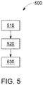
- FIG. 5 is an exemplary illustration of a method 500 of obtaining color appearance via the control system while performing sensing and communication between the control system and an outdoor lighting system that can be implemented within one or more embodiments of the present invention.
- the method 500 begins at operation 510, providing a cover formed at least partially transparent for housing at least one sensor for performing sensing and wireless communication with the outdoor lighting system.
- the method continues to operation 520 where the control system is physically connected with the lighting fixture.
- the method continues by performing ambient sensing and wireless communication by transmitting signals through the cover and wirelessly connecting the control system to the outdoor lighting system to receive and transmit data from the outdoor lighting system.
- Fig. 6 is a detailed schematic illustrating the control system that can be implemented within one or more alternative embodiments of the present invention.
- the control system 600 is similar to the control system 300 except it can be disposed within the lighting fixture 230 in a more compact manner.
- the control system 600 includes a cover 610 to house a PCB stack that includes a circuit board 620 which is similar to the first circuit board 320 and the second circuit board 322 (as depicted in Fig. 4 ) combined together into one circuit board including a network interface unit (e.g., a network interface card) to perform communication with external systems, and other components and associated RF circuitry for operation of an RF antenna which can be disposed on top of the cover 610 in accordance with one or more embodiments.
- the board 620 also includes at least one microprocessor/processing unit for performing calculations using information from the lighting system 200 and at least one sensor and/or a plurality of LEDs, and a driver to control the LEDs.
- a power board assembly 630 is similar to the power board assembly 324 (as depicted in Fig. 3 ) and includes a relay for completing the circuit with the lighting fixture 230 and operates as a lighting controller to turn the lighting fixture 230 on or off.
- the power board assembly 360 can also supply power to the lighting system 200.
- the power board assembly 324 can be an optional component and the node can receive power directly from the lighting driver of the lighting fixture 200.
- the control system 600 includes a base housing 640 which directly connects to the lighting fixture 230 by a connection means such as screws. Therefore, a connector (e.g., a NEMA connector) is not required to perform the connection between the control system 600 and the outdoor lighting system 200 in this embodiment.
- wires 650 are used to facilitate an electrical connection between the node and the lighting fixture 230.
- a photocell 670 is also provided between the circuit board 620 and the power board assembly 630 to perform ambient sensing. Alternatively, the photocell 670 can be positioned on either board 620 or the power board assembly 630.
- the cover 610 is securely fitted into the base housing 640 in a snap fit or locking manner, to complete the external appearance of the control system 600.
Landscapes
- Engineering & Computer Science (AREA)
- Computer Networks & Wireless Communication (AREA)
- Physics & Mathematics (AREA)
- General Physics & Mathematics (AREA)
- Circuit Arrangement For Electric Light Sources In General (AREA)
Abstract
Description
- The present invention is a non-provisional application claiming priority to Provisional Application No.
62/268,485 29/548,803 both filed on December 16, 2015 - The present invention relates generally to an outdoor communication system (e.g., an outdoor lighting system or traffic controllers). In particular, the present invention relates to a control system for obtaining color appearance of an outdoor communication system.
- An outdoor lighting system, such as a roadway/outdoor lighting system, includes one or more lighting fixtures, each fixture typically providing illumination to surroundings within close proximity thereof. Such lighting fixtures can be found along the streets and street corners, and at roadway intersections.
- The lighting fixtures also provide visibility during nighttime hours for security and safety purposes. These fixtures are generally positioned along streets and highways to enable pedestrian traffic and vehicle traffic to safely navigate the roadway after hours and in low lit areas.
- The lighting fixtures are typically mounted on street poles as shown in
Fig. 1. Fig. 1 depicts a conventional roadwayoutdoor lighting system 50, including apole 10, amast arm 20 connected to thepole 10 at a proximal end. Also, included is alighting fixture 30 physically coupled to a distal and of themast arm 20. The roadwayoutdoor lighting system 50 is typically disposed in the ground at a bottom of thepole 10. - The
mast arm 20 includes electrical wiring for connecting and energizing the lighting fixture via a utility grid. Thelighting fixture 30 typically includes alighting device 32 and a connector 40 (e.g., a NEMA® socket) at a top surface thereof for connecting to a control system including housing having a wireless node orphotocell 45 for controlling thelighting fixture 30. - The poles of the roadway/street lighting systems are increasingly being used to perform other functions such as remote monitoring, utility energy management and global positioning system (GPS) mapping, in addition to providing lighting. Therefore, the wireless node needs to be colored per necessary requirements and capable of allowing communication at various frequencies.
- The housing of the wireless node is typically formed with two or more plastic components (e.g., a window and a cover as shown in
Fig. 1 ). The components can be attached together via mechanical fixation or manufacturing methods such as ultrasonic welding or snaps. The node allows light spectrum display and sensing through the window. - There are several challenges associated with the mechanical design and the manufacturing thereof since unfavorable environmental factors (e.g., temperature conditions, or wind or other environmental conditions) can diminish performance. Therefore, additional components (e.g., gaskets and other hardware) and manufacturing processes may be necessary that incur additional costs for attempting to mitigate the impact of an unfavorable environment, and provide a reliable outdoor wireless control system.
- Given the aforementioned deficiencies, a need exists for more adaptable cover or housing for outdoor lighting control system for outdoor lighting systems.
- Under certain circumstances, embodiments of the present invention provide a control system for an outdoor communication system mounted to a fixture of the outdoor communication system. The control system includes at least one sensor configured to sense and perform wireless communication, and a cover formed at least partially transparent and configured to house the at least one sensor and transmit signals through the cover for wireless communication with the outdoor communication system.
- In another exemplary embodiment, a cover formed at least partially transparent for a control system of an outdoor communication system is provided. The cover includes a transparent colored polymeric based material configured to transmit signals therethrough from a wireless node housed therein.
- In yet another exemplary embodiment, a method for obtaining a color appearance during control of an outdoor communication system having a fixture, wherein a control system is mounted to the fixture. The method includes providing a cover formed at least partially transparent for housing at least one sensor for performing sensing with the outdoor communication system, and performing ambient sensing and wireless communication by transmitting signals through the cover and wirelessly connecting the control system to the outdoor communication system to receive and transmit data from the outdoor communication system.
- The foregoing has broadly outlined some of the aspects and features of various embodiments, which should be construed to be merely illustrative of various potential applications of the disclosure. Other beneficial results can be obtained by applying the disclosed information in a different manner or by combining various aspects of the disclosed embodiments. Accordingly, other aspects and a more comprehensive understanding may be obtained by referring to the detailed description of the exemplary embodiments taken in conjunction with the accompanying drawings, in addition to the scope defined by the claims.
-
-
FIG. 1 is a schematic illustrating a conventional outdoor lighting system. -
FIG. 2 is a schematic illustrating the control system for an outdoor lighting system that can be implemented within one or more embodiments. -
FIGS. 3A and 3B are schematics illustrating a cover of the control system shown inFIG. 2 that can be implemented within one or more embodiments of the present invention. -
FIG. 4 is a detailed schematic illustrating the control system that can be implemented within one or more embodiments of the present invention. -
FIG. 5 is a flow chart illustrating a method of obtaining color appearance via the control system while performing sensing and communication between the control system and an outdoor lighting system that can be implemented within one or more embodiments of the present invention. -
FIG. 6 is a detailed schematic illustrating the control system that can be implemented within one or more alternative embodiments of the present invention. - The drawings are only for purposes of illustrating preferred embodiments and are not to be construed as limiting the disclosure. Given the following enabling description of the drawings, the novel aspects of the present disclosure should become evident to a person of ordinary skill in the art. This detailed description uses numerical and letter designations to refer to features in the drawings. Like or similar designations in the drawings and description have been used to refer to like or similar parts of embodiments of the invention.
- As required, detailed embodiments are disclosed herein. It must be understood that the disclosed embodiments are merely exemplary of various and alternative forms. As used herein, the word "exemplary" is used expansively to refer to embodiments that serve as illustrations, specimens, models, or patterns. The figures are not necessarily to scale and some features may be exaggerated or minimized to show details of particular components.
- In other instances, well-known components, systems, materials, or methods that are known to those having ordinary skill in the art have not been described in detail in order to avoid obscuring the present disclosure. Therefore, specific structural and functional details disclosed herein are not to be interpreted as limiting, but merely as a basis for the claims and as a representative basis for teaching one skilled in the art.
- As noted above, the embodiments provide a control system including a cover comprising a wireless node to an outdoor communication system (e.g., an outdoor lighting system or traffic control system). The control system can receive both power and data from the lighting fixture of the outdoor lighting system. The control system can be implemented within existing outdoor lighting systems and provides sensing and communication capabilities for example, for remote monitoring and operation of lighting devices within the outdoor lighting system, obtaining utility energy measurement data and performing GPS mapping of the lighting devices.
-
FIG. 2 is a schematic illustrating the control system for anoutdoor lighting system 200 that can be implemented within one or more embodiments. Theoutdoor lighting system 200 includes a connector orplug 240 at a top surface of thelighting fixture 230, and a web interface and external system for controlling thelighting system 200. According to one or more embodiments, the connector orplug 240 can be a NEMA® socket, two-prong or three-prong socket or any other type of connector suitable for the purposes set forth herein. -
FIGS. 3A and 3B are schematics illustrating a cover of the control system shown inFIG. 2 that can be implemented within one or more embodiments of the present invention. -
FIG. 3A depicts acontrol system 300 mounted to the connector orplug 240 in accordance with one or more embodiments of the present invention. Thecontrol system 300 can be connected by a connector or other interface unit. Thecontrol system 300 includes acover 310. - The
cover 310 is may be fully transparent or at least partially transparent. For example, it may be translucent and/or tinted. According to one or more embodiments, the transparent material can be a transparent polymeric based material. Thecover 310 can appear to be black or another color while allowing flashing LEDs (as depicted inFig. 4 ) of thecontrol system 300 to communicate and the photosensor or node therein to operate. According to one or more embodiments,cover 310 is a single element which can include a window or recess that is integrally formed therein during manufacturing which is translucent to allow the photosensor or node therein to operate. Unlike the conventional housing shown inFIG. 1 , thesingle cover 310 of the present invention therefore provides the advantage of preventing water ingress between separate components having to be sealed together during manufacturing. -
Fig. 3B illustrates the interior areas of thecover 310. The interior areas include anupper portion 310a, amiddle portion 310b and abottom portion 310c. Theupper portion 310a houses a main circuit board, photosensor or node and LEDs. Themiddle portion 310 houses the microprocessor/processing unit for the wireless node, and thelower portion 310c includes the contacts and power pins for connecting the node to thelighting fixture 230. Additional details for the components of thecontrol system 300 will be discussed below with reference toFig. 4 . - As shown in
Fig. 4 , thecontrol system 300 includes thecover 310, and afirst circuit board 320 including a network interface unit (e.g., a network interface card) to perform communication with external systems, and other components. Thefirst circuit board 320 also includes RF antenna and associated circuitry for operation thereof. - The
control system 300 also includes a second circuit board 322 (i.e., the main board or motherboard), including a photosensor for performing ambient sensing, and at least one microprocessor/processing unit for performing calculations using information from thelighting system 200. Thesecond circuit board 322 further includes at least one sensor and/or a plurality of LEDs, and a driver to control the LEDs. The LEDs indicate a state of thecontrol system 300 such as, initialization, initialization failure, connection established, etc. Thesecond circuit board 322 can perform auto detection to detect if the driver is a 0-10Voltg type or a digital addressable lighting interface (DALI) interface. - As further discussed below in reference to
Fig. 6 , thefirst circuit board 320 and thesecond circuit board 322 can be combined into one single board in accordance with one or more embodiments. - The
control system 300 further includes apower board assembly 324 can include a microprocessor/processing unit. Thepower board assembly 324 can be a power interface including a relay for completing the circuit with thelighting fixture 230 and operating as a lighting controller to turn thelighting fixture 230 on or off. Thepower board assembly 324 can also supply power to thelighting system 200. Thepower board assembly 324 can be an optional component and the node can receive power directly from the lighting driver of thelighting fixture 200. Thecontrol system 300 can also include an on-board microcontroller/processing unit, as well as an onboard GPS. - The
control system 300 further includes abase portion 326 to be securely fitted to thecover 310 in a snap-fit manner, for example. - Additional components, including a sealing means (i.e., an o-ring) 328 and a gasket (i.e., a sponge gasket) 330 are provided to seal the connection between the
control system 300 and theexternal connector 240 of thelighting fixture 230, as shown inFig. 2 . - Further, power pins 332 and
contacts 334 are included to provide electrical connection between thelighting fixture 230 and thecontrol system 300 via theexternal connector 240. Thecontacts 334 can include a USB for connecting to external sensors, and other components. Thecontrol system 300 can receive power from thelighting fixture 230 via a power circuit of thelighting fixture 230. - According to the embodiments, the one or more sensors can preferably include a sensor for obtaining external sensing data, for monitoring the system itself. The one or more sensors can also monitor air quality wind velocity, weather conditions, traffic conditions, and corrosion and vibration conditions in addition to controlling and monitoring the functions and power of the
lighting system 200. The present invention is not limited to any particular sensor implementation. - The
control system 300 can wirelessly communicate with thelighting system 200 via a wireless data source in accordance with alternative embodiments of the present invention. The wireless data source can be a radio frequency (RF), cellular, or any other type of robust wireless data source. If RF is used, alternatively the RF can be the wireless power source wirelessly connecting thecontrol system 300 to thelighting fixture 230. Thecontrol system 300 can further wirelessly communicate with thelighting fixture 230 via a designated wireless data circuit. - The
control system 300 can be in wireless communication with at least one external system (e.g., a computer system) for obtaining the sensing data to monitor and control theoutdoor lighting system 200. Thecontrol system 300 can receive command signals from the external system and transmit the sensing data in response to the command signals received. -
FIG. 5 is an exemplary illustration of amethod 500 of obtaining color appearance via the control system while performing sensing and communication between the control system and an outdoor lighting system that can be implemented within one or more embodiments of the present invention. Themethod 500 begins atoperation 510, providing a cover formed at least partially transparent for housing at least one sensor for performing sensing and wireless communication with the outdoor lighting system. - The method continues to
operation 520 where the control system is physically connected with the lighting fixture. - At
operation 530, the method continues by performing ambient sensing and wireless communication by transmitting signals through the cover and wirelessly connecting the control system to the outdoor lighting system to receive and transmit data from the outdoor lighting system. -
Fig. 6 is a detailed schematic illustrating the control system that can be implemented within one or more alternative embodiments of the present invention. In this embodiment of the present invention, thecontrol system 600 is similar to thecontrol system 300 except it can be disposed within thelighting fixture 230 in a more compact manner. - As shown in
Fig. 6 , the control system (i.e., the node) 600 includes acover 610 to house a PCB stack that includes acircuit board 620 which is similar to thefirst circuit board 320 and the second circuit board 322 (as depicted inFig. 4 ) combined together into one circuit board including a network interface unit (e.g., a network interface card) to perform communication with external systems, and other components and associated RF circuitry for operation of an RF antenna which can be disposed on top of thecover 610 in accordance with one or more embodiments. Theboard 620 also includes at least one microprocessor/processing unit for performing calculations using information from thelighting system 200 and at least one sensor and/or a plurality of LEDs, and a driver to control the LEDs. - A
power board assembly 630 is similar to the power board assembly 324 (as depicted inFig. 3 ) and includes a relay for completing the circuit with thelighting fixture 230 and operates as a lighting controller to turn thelighting fixture 230 on or off. The power board assembly 360 can also supply power to thelighting system 200. Thepower board assembly 324 can be an optional component and the node can receive power directly from the lighting driver of thelighting fixture 200. In addition, thecontrol system 600 includes abase housing 640 which directly connects to thelighting fixture 230 by a connection means such as screws. Therefore, a connector (e.g., a NEMA connector) is not required to perform the connection between thecontrol system 600 and theoutdoor lighting system 200 in this embodiment. - As further shown in
Fig. 6 ,wires 650 are used to facilitate an electrical connection between the node and thelighting fixture 230. Aphotocell 670 is also provided between thecircuit board 620 and thepower board assembly 630 to perform ambient sensing. Alternatively, thephotocell 670 can be positioned on eitherboard 620 or thepower board assembly 630. - The
cover 610 is securely fitted into thebase housing 640 in a snap fit or locking manner, to complete the external appearance of thecontrol system 600. - This written description uses examples to disclose the invention including the best mode, and also to enable any person skilled in the art to practice the invention, including making and using any devices or systems and performing any incorporated methods. The patentable scope of the invention is defined by the claims, and may include other examples that occur to those skilled in the art. Such other examples are intended to be within the scope of the claims if they have structural elements that do not differ from the literal language of the claims, or if they include equivalent structural elements with insubstantial differences from the literal languages of the claims.
Claims (11)
- A control system (300) for an outdoor communication system (200) mounted to a fixture (230) of the outdoor communication system (200), the control system (300) comprising:at least one sensor (670) configured to sense and perform wireless communication; anda cover (310) formed at least partially transparent and configured to house the at least one sensor (670) and transmit signals through the cover (310) for wireless communication with the outdoor communication system.
- The control system (300) of claim 1, wherein the outdoor communication system (200) includes an outdoor lighting system.
- The control system (300) of claim 1 or claim 2, wherein the cover (310) is a single component formed of a transparent polymeric material.
- The control system (300) of any preceding claim, further comprising:a first circuit board (320) including a network interface unit to perform communication with an external system; anda second circuit board (322) connected with the first circuit board (320) and including the at least one sensor (670) and at least one processing unit for performing calculations using information from the outdoor communication system (200).
- The control system (300) of claim 4, wherein the second circuit board (322) further includes a plurality of light emitting diodes configured to indicate a state of the control system (300) and a driver configured to control the light emitting diodes.
- The control system (300) of claim 5, wherein second circuit board (322) is configured to perform auto detection to detect if the driver of the outdoor communication system (200) comprises a 0-10Volt protocol or a digital addressable lighting interface (DALI) interface.
- The control system (300) of any of claims 4 to 6, further comprising:a power board assembly(324) comprising:a power interface including a relay for completing a circuit with the fixture (230) and operating as a controller to turn on and off the fixture (230) of the outdoor communication system (200).
- The control system (300) of any of claims 4 to 7, further comprising:a base portion (326) to enclose the first circuit board (320), second circuit board (322) and the power board assembly (324) of the control system (300) and configured to be securely fitted to the cover (310).
- The control system (300, 600) of any of claims 4 to 8, wherein the first circuit board (320) and the second circuit board (322) are combined into a single circuit board (620).
- The control system (300, 600) of any of claims 4 to 9, wherein the single circuit board (620) and the power board assembly (324, 630) form a PCB stack within the cover (310, 610).
- The control system (300) of any preceding claim, wherein the cover (310) is translucent and/or tinted.
Applications Claiming Priority (2)
| Application Number | Priority Date | Filing Date | Title |
|---|---|---|---|
| US201562268485P | 2015-12-16 | 2015-12-16 | |
| US15/368,711 US10068468B2 (en) | 2015-12-16 | 2016-12-05 | Control system for an outdoor communication system |
Publications (1)
| Publication Number | Publication Date |
|---|---|
| EP3182808A1 true EP3182808A1 (en) | 2017-06-21 |
Family
ID=57539180
Family Applications (1)
| Application Number | Title | Priority Date | Filing Date |
|---|---|---|---|
| EP16203318.7A Withdrawn EP3182808A1 (en) | 2015-12-16 | 2016-12-09 | Control system for an outdoor communication system |
Country Status (4)
| Country | Link |
|---|---|
| US (1) | US10068468B2 (en) |
| EP (1) | EP3182808A1 (en) |
| CN (1) | CN106912147A (en) |
| CA (1) | CA2951104A1 (en) |
Cited By (2)
| Publication number | Priority date | Publication date | Assignee | Title |
|---|---|---|---|---|
| WO2019215657A1 (en) * | 2018-05-11 | 2019-11-14 | Te Connectivity Corporation | Local luminaire area control system |
| DE102018115842A1 (en) | 2018-06-29 | 2020-01-02 | Vossloh-Schwabe Deutschland Gmbh | Radio module, light and method for equipping a light with a radio module |
Families Citing this family (10)
| Publication number | Priority date | Publication date | Assignee | Title |
|---|---|---|---|---|
| WO2018102024A1 (en) | 2016-12-02 | 2018-06-07 | Cooper Technologies Company | Antennae for hazardous location light fixtures |
| US10904992B2 (en) | 2017-04-03 | 2021-01-26 | Express Imaging Systems, Llc | Systems and methods for outdoor luminaire wireless control |
| US11375599B2 (en) | 2017-04-03 | 2022-06-28 | Express Imaging Systems, Llc | Systems and methods for outdoor luminaire wireless control |
| US10568191B2 (en) * | 2017-04-03 | 2020-02-18 | Express Imaging Systems, Llc | Systems and methods for outdoor luminaire wireless control |
| US10575385B2 (en) * | 2018-05-11 | 2020-02-25 | Te Connectivity Corporation | Sensor element for a local luminaire area control system |
| US11234304B2 (en) | 2019-05-24 | 2022-01-25 | Express Imaging Systems, Llc | Photocontroller to control operation of a luminaire having a dimming line |
| US11317497B2 (en) | 2019-06-20 | 2022-04-26 | Express Imaging Systems, Llc | Photocontroller and/or lamp with photocontrols to control operation of lamp |
| EP4133211B1 (en) * | 2020-04-10 | 2024-01-31 | Signify Holding B.V. | Outdoor electrical device, controller and mounting method |
| RU209010U1 (en) * | 2021-10-04 | 2022-01-27 | Общество с ограниченной ответственностью "РЭСТО" | Outdoor LED Light Control Module |
| US12439488B2 (en) | 2022-12-09 | 2025-10-07 | Express Imaging Systems, Llc | Field adjustable output for dimmable luminaires |
Citations (7)
| Publication number | Priority date | Publication date | Assignee | Title |
|---|---|---|---|---|
| US20040192415A1 (en) * | 2003-03-25 | 2004-09-30 | Silver Spring Networks, Inc. | Wireless communication system |
| US7569802B1 (en) * | 2003-03-20 | 2009-08-04 | Patrick Mullins | Photosensor control unit for a lighting module |
| US20100029268A1 (en) * | 2007-02-02 | 2010-02-04 | Ming Solar, Inc., Dba Inovus Solar, Inc. | Wireless autonomous solar-powered outdoor lighting and energy and information management network |
| US20110060701A1 (en) * | 2009-09-04 | 2011-03-10 | Orion Energy Systems, Inc. | Outdoor fluorescent lighting fixtures and related systems and methods |
| US20120040606A1 (en) * | 2007-06-29 | 2012-02-16 | Orion Energy Systems, Inc. | Outdoor lighting systems and methods for wireless network communications |
| US20120139426A1 (en) * | 2010-12-03 | 2012-06-07 | General Electric Company | Dimmable outdoor luminaires |
| WO2013159833A1 (en) * | 2012-04-27 | 2013-10-31 | Schreder | Luminaire controllers |
Family Cites Families (19)
| Publication number | Priority date | Publication date | Assignee | Title |
|---|---|---|---|---|
| US1932044A (en) | 1932-03-18 | 1933-10-24 | Westinghouse Electric & Mfg Co | Meter cover |
| US2030094A (en) | 1934-09-13 | 1936-02-11 | Westinghouse Electric & Mfg Co | Meter mounting |
| US2313881A (en) | 1940-06-18 | 1943-03-16 | Westinghouse Electric & Mfg Co | Theftproof meter cover |
| US2461247A (en) | 1945-07-04 | 1949-02-08 | Wormull George | Utility cover |
| USD354113S (en) | 1992-07-22 | 1995-01-03 | Sloan Valve Company | Flush valve cover |
| USD343803S (en) | 1992-08-13 | 1994-02-01 | General Electric Company | Electronic energy meter |
| USD348017S (en) | 1993-02-09 | 1994-06-21 | Grinnell Corporation | Water meter register and housing |
| USD381281S (en) | 1995-11-30 | 1997-07-22 | Miller David J | Electric meter cover |
| USD412859S (en) | 1998-06-24 | 1999-08-17 | Abb Power T&D Company Inc. | Meter cover |
| USD429655S (en) | 1999-08-09 | 2000-08-22 | Power Measurement Ltd. | Electric meter cover |
| US6688327B1 (en) | 2002-11-12 | 2004-02-10 | Mark C. Baker | Water meter cover |
| US8362713B2 (en) * | 2006-03-28 | 2013-01-29 | Wireless Environment, Llc | Wireless lighting devices and grid-shifting applications |
| US7874709B1 (en) * | 2007-11-14 | 2011-01-25 | Hunter Industries Incorporated | Recessed lighting fixture with multiple adjustment axes |
| CN201180934Y (en) * | 2008-02-05 | 2009-01-14 | 吕绍裕 | Outdoor lighting device |
| US7821776B2 (en) | 2008-03-25 | 2010-10-26 | Elster Electricity, Llc | Tamper resistant meter assembly |
| US8823277B2 (en) * | 2008-04-14 | 2014-09-02 | Digital Lumens Incorporated | Methods, systems, and apparatus for mapping a network of lighting fixtures with light module identification |
| WO2010063001A1 (en) * | 2008-11-26 | 2010-06-03 | Wireless Environment, Llc | Wireless lighting devices and applications |
| USD596570S1 (en) | 2009-01-14 | 2009-07-21 | Cisco Technology, Inc. | Network socket |
| US20120086561A1 (en) * | 2010-10-07 | 2012-04-12 | General Electric Company | Outdoor lighting system |
-
2016
- 2016-12-05 US US15/368,711 patent/US10068468B2/en active Active
- 2016-12-08 CA CA2951104A patent/CA2951104A1/en not_active Abandoned
- 2016-12-09 EP EP16203318.7A patent/EP3182808A1/en not_active Withdrawn
- 2016-12-16 CN CN201611167774.9A patent/CN106912147A/en active Pending
Patent Citations (7)
| Publication number | Priority date | Publication date | Assignee | Title |
|---|---|---|---|---|
| US7569802B1 (en) * | 2003-03-20 | 2009-08-04 | Patrick Mullins | Photosensor control unit for a lighting module |
| US20040192415A1 (en) * | 2003-03-25 | 2004-09-30 | Silver Spring Networks, Inc. | Wireless communication system |
| US20100029268A1 (en) * | 2007-02-02 | 2010-02-04 | Ming Solar, Inc., Dba Inovus Solar, Inc. | Wireless autonomous solar-powered outdoor lighting and energy and information management network |
| US20120040606A1 (en) * | 2007-06-29 | 2012-02-16 | Orion Energy Systems, Inc. | Outdoor lighting systems and methods for wireless network communications |
| US20110060701A1 (en) * | 2009-09-04 | 2011-03-10 | Orion Energy Systems, Inc. | Outdoor fluorescent lighting fixtures and related systems and methods |
| US20120139426A1 (en) * | 2010-12-03 | 2012-06-07 | General Electric Company | Dimmable outdoor luminaires |
| WO2013159833A1 (en) * | 2012-04-27 | 2013-10-31 | Schreder | Luminaire controllers |
Cited By (5)
| Publication number | Priority date | Publication date | Assignee | Title |
|---|---|---|---|---|
| WO2019215657A1 (en) * | 2018-05-11 | 2019-11-14 | Te Connectivity Corporation | Local luminaire area control system |
| US10624179B2 (en) | 2018-05-11 | 2020-04-14 | Te Connectivity Corporation | Local luminaire area control system |
| CN112154714A (en) * | 2018-05-11 | 2020-12-29 | 泰连公司 | Local illumination area control system |
| CN112154714B (en) * | 2018-05-11 | 2023-08-22 | 泰连公司 | Local illumination zone control system |
| DE102018115842A1 (en) | 2018-06-29 | 2020-01-02 | Vossloh-Schwabe Deutschland Gmbh | Radio module, light and method for equipping a light with a radio module |
Also Published As
| Publication number | Publication date |
|---|---|
| CA2951104A1 (en) | 2017-06-16 |
| US10068468B2 (en) | 2018-09-04 |
| CN106912147A (en) | 2017-06-30 |
| US20170178497A1 (en) | 2017-06-22 |
Similar Documents
| Publication | Publication Date | Title |
|---|---|---|
| US10068468B2 (en) | Control system for an outdoor communication system | |
| US9945960B2 (en) | Luminaire associate | |
| JP3145419U (en) | Non-contact light emitting display device for transportation / transportation | |
| US9974143B2 (en) | Light sensor assembly having wireless data transfer | |
| EP3278633B1 (en) | Precipitation sensing luminaire | |
| US8310092B2 (en) | Outdoor electrical power receptacle and control system thereof | |
| KR20170107206A (en) | Road stud detecting the condition of the road | |
| US10104746B2 (en) | Wireless connection of sensors to outdoor lighting system | |
| US11187404B2 (en) | Lighting receptacle assembly for light fixture | |
| US20190186719A1 (en) | Environmental sensor for a light sensor assembly | |
| CN205656189U (en) | Small -size showy formula water quality automatic monitoring buoy | |
| KR101099390B1 (en) | LED bridge table remote control system | |
| ES2952778T3 (en) | Wireless detection apparatus and method | |
| CN203240472U (en) | LED radar induction lamp | |
| CN210835658U (en) | Remote monitoring system applied to well lid | |
| US12098831B1 (en) | Systems methods and internal control devices for wireless light-fixtures control | |
| KR200449096Y1 (en) | Luminaire | |
| CN208295775U (en) | Street lamp monitors system | |
| CN110675765A (en) | Intelligent 3D suspension screen | |
| CN111988086A (en) | Fixed asset tracking system and method | |
| KR20210072259A (en) | Internet of Things Datum Point Device | |
| CN210157435U (en) | Multifunctional lamp | |
| CN211237127U (en) | Warning pedestrian crossing signal lamp for foggy days | |
| CN209562580U (en) | A multifunctional IoT gateway based on NB-IOT | |
| CN212115749U (en) | Remote control and remote measurement system for synchronous flashing beacon light |
Legal Events
| Date | Code | Title | Description |
|---|---|---|---|
| PUAI | Public reference made under article 153(3) epc to a published international application that has entered the european phase |
Free format text: ORIGINAL CODE: 0009012 |
|
| STAA | Information on the status of an ep patent application or granted ep patent |
Free format text: STATUS: THE APPLICATION HAS BEEN PUBLISHED |
|
| AK | Designated contracting states |
Kind code of ref document: A1 Designated state(s): AL AT BE BG CH CY CZ DE DK EE ES FI FR GB GR HR HU IE IS IT LI LT LU LV MC MK MT NL NO PL PT RO RS SE SI SK SM TR |
|
| AX | Request for extension of the european patent |
Extension state: BA ME |
|
| STAA | Information on the status of an ep patent application or granted ep patent |
Free format text: STATUS: REQUEST FOR EXAMINATION WAS MADE |
|
| 17P | Request for examination filed |
Effective date: 20171221 |
|
| RBV | Designated contracting states (corrected) |
Designated state(s): AL AT BE BG CH CY CZ DE DK EE ES FI FR GB GR HR HU IE IS IT LI LT LU LV MC MK MT NL NO PL PT RO RS SE SI SK SM TR |
|
| STAA | Information on the status of an ep patent application or granted ep patent |
Free format text: STATUS: THE APPLICATION IS DEEMED TO BE WITHDRAWN |
|
| 18D | Application deemed to be withdrawn |
Effective date: 20200701 |