EP3182669A1 - Integrated industrial system and control method thereof - Google Patents
Integrated industrial system and control method thereof Download PDFInfo
- Publication number
- EP3182669A1 EP3182669A1 EP16203442.5A EP16203442A EP3182669A1 EP 3182669 A1 EP3182669 A1 EP 3182669A1 EP 16203442 A EP16203442 A EP 16203442A EP 3182669 A1 EP3182669 A1 EP 3182669A1
- Authority
- EP
- European Patent Office
- Prior art keywords
- zone
- cyber
- attack
- integrated industrial
- countermeasure
- Prior art date
- Legal status (The legal status is an assumption and is not a legal conclusion. Google has not performed a legal analysis and makes no representation as to the accuracy of the status listed.)
- Granted
Links
Images



Classifications
-
- H—ELECTRICITY
- H04—ELECTRIC COMMUNICATION TECHNIQUE
- H04L—TRANSMISSION OF DIGITAL INFORMATION, e.g. TELEGRAPHIC COMMUNICATION
- H04L63/00—Network architectures or network communication protocols for network security
- H04L63/14—Network architectures or network communication protocols for network security for detecting or protecting against malicious traffic
- H04L63/1441—Countermeasures against malicious traffic
- H04L63/1466—Active attacks involving interception, injection, modification, spoofing of data unit addresses, e.g. hijacking, packet injection or TCP sequence number attacks
-
- G—PHYSICS
- G06—COMPUTING OR CALCULATING; COUNTING
- G06F—ELECTRIC DIGITAL DATA PROCESSING
- G06F21/00—Security arrangements for protecting computers, components thereof, programs or data against unauthorised activity
- G06F21/50—Monitoring users, programs or devices to maintain the integrity of platforms, e.g. of processors, firmware or operating systems
- G06F21/55—Detecting local intrusion or implementing counter-measures
- G06F21/554—Detecting local intrusion or implementing counter-measures involving event detection and direct action
-
- H—ELECTRICITY
- H04—ELECTRIC COMMUNICATION TECHNIQUE
- H04L—TRANSMISSION OF DIGITAL INFORMATION, e.g. TELEGRAPHIC COMMUNICATION
- H04L63/00—Network architectures or network communication protocols for network security
- H04L63/02—Network architectures or network communication protocols for network security for separating internal from external traffic, e.g. firewalls
-
- G—PHYSICS
- G05—CONTROLLING; REGULATING
- G05B—CONTROL OR REGULATING SYSTEMS IN GENERAL; FUNCTIONAL ELEMENTS OF SUCH SYSTEMS; MONITORING OR TESTING ARRANGEMENTS FOR SUCH SYSTEMS OR ELEMENTS
- G05B19/00—Program-control systems
- G05B19/02—Program-control systems electric
- G05B19/04—Program control other than numerical control, i.e. in sequence controllers or logic controllers
- G05B19/042—Program control other than numerical control, i.e. in sequence controllers or logic controllers using digital processors
- G05B19/0428—Safety, monitoring
-
- G—PHYSICS
- G05—CONTROLLING; REGULATING
- G05B—CONTROL OR REGULATING SYSTEMS IN GENERAL; FUNCTIONAL ELEMENTS OF SUCH SYSTEMS; MONITORING OR TESTING ARRANGEMENTS FOR SUCH SYSTEMS OR ELEMENTS
- G05B19/00—Program-control systems
- G05B19/02—Program-control systems electric
- G05B19/04—Program control other than numerical control, i.e. in sequence controllers or logic controllers
- G05B19/048—Monitoring; Safety
-
- G—PHYSICS
- G06—COMPUTING OR CALCULATING; COUNTING
- G06F—ELECTRIC DIGITAL DATA PROCESSING
- G06F21/00—Security arrangements for protecting computers, components thereof, programs or data against unauthorised activity
- G06F21/50—Monitoring users, programs or devices to maintain the integrity of platforms, e.g. of processors, firmware or operating systems
- G06F21/55—Detecting local intrusion or implementing counter-measures
- G06F21/56—Computer malware detection or handling, e.g. anti-virus arrangements
- G06F21/561—Virus type analysis
-
- G—PHYSICS
- G06—COMPUTING OR CALCULATING; COUNTING
- G06F—ELECTRIC DIGITAL DATA PROCESSING
- G06F21/00—Security arrangements for protecting computers, components thereof, programs or data against unauthorised activity
- G06F21/50—Monitoring users, programs or devices to maintain the integrity of platforms, e.g. of processors, firmware or operating systems
- G06F21/57—Certifying or maintaining trusted computer platforms, e.g. secure boots or power-downs, version controls, system software checks, secure updates or assessing vulnerabilities
-
- H—ELECTRICITY
- H04—ELECTRIC COMMUNICATION TECHNIQUE
- H04L—TRANSMISSION OF DIGITAL INFORMATION, e.g. TELEGRAPHIC COMMUNICATION
- H04L63/00—Network architectures or network communication protocols for network security
- H04L63/14—Network architectures or network communication protocols for network security for detecting or protecting against malicious traffic
-
- H—ELECTRICITY
- H04—ELECTRIC COMMUNICATION TECHNIQUE
- H04L—TRANSMISSION OF DIGITAL INFORMATION, e.g. TELEGRAPHIC COMMUNICATION
- H04L67/00—Network arrangements or protocols for supporting network services or applications
- H04L67/01—Protocols
- H04L67/10—Protocols in which an application is distributed across nodes in the network
-
- H—ELECTRICITY
- H04—ELECTRIC COMMUNICATION TECHNIQUE
- H04L—TRANSMISSION OF DIGITAL INFORMATION, e.g. TELEGRAPHIC COMMUNICATION
- H04L67/00—Network arrangements or protocols for supporting network services or applications
- H04L67/01—Protocols
- H04L67/12—Protocols specially adapted for proprietary or special-purpose networking environments, e.g. medical networks, sensor networks, networks in vehicles or remote metering networks
-
- G—PHYSICS
- G05—CONTROLLING; REGULATING
- G05B—CONTROL OR REGULATING SYSTEMS IN GENERAL; FUNCTIONAL ELEMENTS OF SUCH SYSTEMS; MONITORING OR TESTING ARRANGEMENTS FOR SUCH SYSTEMS OR ELEMENTS
- G05B2219/00—Program-control systems
- G05B2219/20—Pc systems
- G05B2219/23—Pc programming
- G05B2219/23317—Safe mode, secure program, environment in case of error, intrusion
Definitions
- the disclosure relates to an integrated industrial system and a control method thereof.
- the integrated industrial system includes a control system such as a distributed control system (DCS) and a safety system such as a safety instrumented system (SIS).
- DCS distributed control system
- SIS safety instrumented system
- the distributed control system is a process control system which controls industrial process implemented in the plant.
- field devices for example, a measurement device and an actuation device
- a controller which controls these field devices are connected to each other through communication means.
- the controller collects measurement data measured by a field device, and operates (controls) a field device in accordance with the collected measurement data.
- the distributed control system controls various kinds of state quantity in the industrial process.
- the safety instrumented system certainly shuts down the plant in a safe state.
- the safety instrumented system prevents a physical injury and an environmental pollution, and protects expensive facilities.
- the safety instrumented system plays a role of "stronghold for securing safety".
- countermeasures for a case that each of the distributed control system and the safety instrumented system receives cyber-attacks, or for a case that the whole integrated industrial system receives cyber-attacks, are prepared.
- a firewall for preventing intrusion from outside to the integrated industrial system is prepared, or antivirus software (software which detects virus infection and removes virus) is installed in a computer.
- the controller which is a core of the distributed control system and the safety instrumented system has a high resistance against cyber-attacks by using an original operating system.
- the integrated industrial system is sectioned into two or more zones, and the security countermeasures are basically applied to each zone.
- an integrated industrial system established in conformity with hierarchical structures specified by International Standard ISA-95 (IEC/ISO 62264) is sectioned into two or more zones on the basis of hierarchy.
- the security countermeasures are applied to each hierarchy.
- a conventional technology for maintaining security of a control network is disclosed in Japanese Unexamined Patent Application Publication No. 2000-267957 and Japanese Unexamined Patent Application Publication No. 2010-081610 .
- a conventional technology for displaying a tree view in accordance with hierarchical structure of International Standard ISA-95 is disclosed in Japanese Unexamined Patent Application Publication No. 2013-161432 .
- the security countermeasures against cyber-attacks from the outside are basically applied to each zone, the security countermeasures are individually performed in each zone when cyber-attacks are performed. For this reason, in the conventional integrated industrial system, if the security countermeasures of each zone are not enough with respect to cyber-attacks, the cyber-attacks reach the zone where the safety instrumented system belongs. For this reason, there is a problem that final defense countermeasures depend on security countermeasures applied to the zone where the safety instrumented system belongs.
- the safety instrumented system does not usually communicate with a host system, but the safety instrumented system communicates with the distributed control system.
- the distributed control system is supposed to communicate with the host system.
- An integrated industrial system may include a safety instrumented system which is installed in a first zone, a host system which is connected to the safety instrumented system through a network, the host system being installed in a second zone which is different from the first zone, a detector which is installed in each of the first zone and the second zone, the detector being configured to detect a cyber-attack from outside to a self-zone, and a defender configured to perform a countermeasure of restricting a communication between the first zone and the second zone or of restricting a communication in the first zone or the second zone, based on a detection result of the detector.
- An aspect of the present invention is to provide an integrated industrial system and a control method thereof which can defend against cyber-attacks to a safety instrumented system beforehand, and can secure a normality of the safety instrumented system.
- FIG. 1 is a block diagram illustrating a whole configuration of the integrated industrial system in the first embodiment of the present invention.
- the integrated industrial system 1 of the present embodiment includes a field device 10, a distributed control system (DCS) 20, a safety instrumented system (SIS) 30, a manufacturing system 40 (a host system; a first system), a managing system 50 (a host system; a second system), a detecting device 60 (detector), and a defense device 70 (defender).
- the integrated industrial system 1 performs automatic operation of a plant, and performs maintenance management of the plant.
- the integrated industrial system 1 is established in conformity with hierarchical structures specified by International Standard ISA-95 (IEC/ISO 62264). Specifically, in the integrated industrial system 1, the distributed control system 20 and the safety instrumented system 30 belong to a hierarchy of level 2, the manufacturing system 40 belongs to a hierarchy of level 3, and the managing system 50 belongs to a hierarchy of level 4.
- the distributed control system 20, the safety instrumented system 30, the manufacturing system 40, the managing system 50, the detecting device 60, and the defense device 70 are connected to each other through a network configured by network devices NE1 to NE6.
- the integrated industrial system 1 is sectioned into two or more zones on the basis of hierarchy in order to prepare security countermeasures. Specifically, in the integrated industrial system 1, the distributed control system 20 and the safety instrumented system 30 are installed in a zone Z1, the manufacturing system 40 is installed in a zone Z2, and the managing system 50 is installed in a zone Z3.
- the plant includes an industrial plant such as a chemical industrial plant, a plant managing and controlling a wellhead (for example, a gas field and an oil field), a plant managing and controlling a generation of electric power (for example, hydro power, thermal power, and nuclear power), a plant managing and controlling a power harvesting (for example, solar power and wind power), a plant managing and controlling water supply and sewerage systems, a dam, and so on.
- an industrial plant such as a chemical industrial plant, a plant managing and controlling a wellhead (for example, a gas field and an oil field), a plant managing and controlling a generation of electric power (for example, hydro power, thermal power, and nuclear power), a plant managing and controlling a power harvesting (for example, solar power and wind power), a plant managing and controlling water supply and sewerage systems, a dam, and so on.
- a plant managing and controlling a wellhead for example, a gas field and an oil field
- a plant managing and controlling a generation of electric power for example, hydro power, thermal power
- the field device 10 is installed at a field of the plant, and the field device performs measurement and actuation required for control of industrial process under control of the distributed control system 20.
- the field device 10 is such as a sensor device (for example, a pressure meter, a flowmeter, a temperature sensor, a gas sensor, and a vibration sensor), a valve device (for example, a flow control valve and an on-off valve), an actuator device (for example, a fan and a motor), an imaging device (for example, a camera and a video camera recording circumstances and objects in the plant), a sound device (for example, a microphone collecting abnormal noise in the plant, and a speaker generating alarm sound), a position detection device outputting position information of the each device, and other devices.
- a sensor device for example, a pressure meter, a flowmeter, a temperature sensor, a gas sensor, and a vibration sensor
- a valve device for example, a flow control valve and an on-off valve
- an actuator device for example, a fan and
- the field device 10 communicates with the distributed control system 20 or the safety instrumented system 30.
- the field device 10 performs wired communication through a network or a communication bus (not shown), or wireless communication in conformity with industrial wireless communication standards, such as ISA100.11a and WirelessHART (registered trademark), with respect to the distributed control system 20 and the safety instrumented system 30.
- the distributed control system 20 is equipped with a process controller 21, an operation monitoring terminal 22, and an engineering terminal 23.
- the distributed control system 20 collects measurement data measured by the field device 10, and operates (controls) the field device 10 in accordance with the collected measurement data, in order to control various kinds of state quantity.
- the state quantity controlled by the distributed control system 20 is various kinds of state quantity in the industrial process.
- the state quantity is pressure, temperature, flow quantity, or the like.
- the process controller 21 is a core of the distributed control system 20.
- the process controller 21 collects the measurement data from the field device 10, and operates (controls) the field device 10.
- the operation monitoring terminal 22 is operated by a plant operator, and the operation monitoring terminal 22 is used for monitoring an operational status of the plant.
- the engineering terminal 23 is a terminal used for creating programs to be executed by the process controller 21.
- the process controller 21, the operation monitoring terminal 22, and the engineering terminal 23 are connected to each other through the network device NE2. For example, if it is not necessary to create the programs to be executed by the process controller 21, the engineering terminal 23 may be omitted, or the engineering terminal 23 does not need to be always connected to the network.
- the safety instrumented system 30 is equipped with a safety controller 31 and an engineering terminal 32. In an emergency, the safety instrumented system 30 certainly shuts down the plant in a safe state, in order to prevent a physical injury and an environmental pollution, and protect expensive facilities. When an abnormal circumstance occurs in the plant, the safety instrumented system plays a role of "stronghold for securing safety".
- the safety controller 31 is a core of the safety instrumented system 30.
- the safety controller 31 communicates with the field device 10 or another safety controller (not shown) and obtains necessary data, in order to determine whether an abnormal circumstance occurs in the plant or not. If the safety controller 31 determines that an abnormal circumstance occurs in the plant, the safety controller 31 executes a safety control logic for implementing safety control.
- the engineering terminal 32 is a terminal used for creating programs to be executed by the safety controller 31.
- the safety controllers 31 and the engineering terminal 32 are connected to each other through the network devices NE1 and NE2. Similar to the engineering terminal 23, for example, if it is not necessary to create the programs to be executed by the safety controller 31, the engineering terminal 32 may be omitted, or the engineering terminal 32 is not always connected to the network.
- the manufacturing system 40 is a system established for manufacturing products in the plant efficiently.
- the manufacturing system 40 is such as a Manufacturing Execution System (MES), a Plant Information Management System (PIMS), and a Plant Asset Management System (PAM).
- MES Manufacturing Execution System
- PIMS Plant Information Management System
- PAM Plant Asset Management System
- the manufacturing system 40 only one of the Manufacturing Execution System, the Plant Information Management System, and the Plant Asset Management System may be established, and two or more of them may be established.
- the manufacturing system 40 is connected to the distributed control system 20 and the safety instrumented system 30 through the network devices NE3 and NE4.
- the managing system 50 is a system established for business, such as management or sales and marketing in a company.
- the managing system 50 is an Enterprise Resource Planning System (ERP).
- ERP Enterprise Resource Planning System
- the managing system 50 is connected to the manufacturing system 40 through the network device NE5, and the managing system 50 is connected to other unillustrated networks (for example, Internet) through the network device NE6.
- the detecting device 60 is installed in each of the zones Z1 to Z3.
- the detecting device 60 detects cyber-attacks from outside to the self-zone.
- the cyber-attacks from outside are such as an unauthorized invasion to the integrated industrial system 1, an alteration of the program used by the integrated industrial system 1, a fraud and a destruction of data used by the integrated industrial system 1, an act for making the integrated industrial system 1 be in malfunction state, and other acts.
- the detecting device 60 is prepared in accordance with a design concept of each of the zones Z1 to Z3.
- the detecting device 60 can utilize commercial antivirus software (software which detects virus infection and removes virus), or utilize an intrusion detection system.
- commercial antivirus software software which detects virus infection and removes virus
- an intrusion detection system e.g., an intrusion detection system.
- the detecting device 60 is prepared as "device" will be described, but the function of the detecting device 60 may be implemented by software.
- the detecting device 60 installed in each of the zones Z1 to Z3 is connected to the network configured by the network devices NE1 to NE6. If the detecting device 60 installed in each of the zones Z1 to Z3 detects cyber-attacks, the detecting device 60 transmits the detection result to the defense device 70 through the network. Specifically, the detecting device 60 installed in the zone Z1 is connected to the network devices NE2 and NE3. The detecting device 60 installed in the zone Z2 is connected to the network devices NE4 and NE5. The detecting device 60 installed in the zone Z3 is connected to the network device NE5 and NE6.
- the network devices NE1 to NE6 are such as a firewall, a router, a switch, and so on.
- the network device NE4 is installed between the zone Z1 and the zone Z2.
- the network device NE5 is installed between the zone Z2 and the zone Z3.
- the network device NE6 is installed between the zone Z3 and another unillustrated network (for example, Internet).
- the network device NE1 is installed between the safety controller 31 and the network device N2.
- the defense device 70 performs security countermeasures for defending against cyber-attacks from outside based on the detection result obtained from the detecting device 60. For example, the defense device 70 performs a countermeasure of restricting a communication between the zones Z1 to Z3, or a countermeasure of restricting a communication in the zone Z1.
- the defense device 70 is installed in the zone Z1 where the safety instrumented system 30 belongs.
- the defense device 70 obtains the detection result of the detecting device 60 through the network configured by the network devices NE1 to NE6, and the defense device 70 performs the security countermeasures through the network configured by the network devices NE1 to NE6.
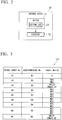
- FIG. 2 is a block diagram illustrating a main configuration of the defense device in the first embodiment of the present invention.
- the defense device 70 is equipped with a setter 71 and an executor 72.
- the setter 71 specifies a target and a type of the cyber-attack based on the detection result of the detecting device 60, and the setter 71 sets security countermeasures in accordance with the specified contents.
- the setter 71 sets the security countermeasures by using a setting list LS in which an attack target list and a countermeasure list are associated with each other.
- the attack target list represents a list of the target and the type of the cyber-attack.
- the countermeasure list represents a list of security countermeasures which should be performed in accordance with the target and the type of the cyber-attack.
- the executor 72 executes security countermeasures which have been set by the setter 71.
- the defense device 70 is prepared as "device" will be described.
- the function of the defense device 70 may be implemented by software.
- FIG. 3 is a drawing illustrating an example of the setting list in the first embodiment of the present invention.
- FIG. 4A is a drawing illustrating an attack target list.
- FIG. 4B is a drawing illustrating a countermeasure list.
- the setting list LS is a list in which "attack target number" (attack target No.) of the attack target list, "countermeasure number” (countermeasure No.) of the countermeasure list, and "target device” have been associated with each other.
- the "target device” is a target to which security countermeasures are to be performed.
- the attack target list is a list in which "attack target number” (attack target No.), "zone”, “device”, “level”, and “type” have been associated with each other.
- the attack target list is a list used for specifying what kind of attack has been made with respect to which zone.
- the "attack target number” is a number allocated for distinguishing various cyber-attacks performed to the integrated industrial system 1.
- the "zone” is information for specifying a zone to which the cyber-attack has been performed.
- the “device” is information for specifying a device to which the cyber-attack has been performed.
- the “device” is such as a personal computer (PC), a controller, a switch, a firewall, and so on.
- the “level” is information for specifying which part of a device has been attacked with the cyber-attack.
- the “level” is such as an operating system (OS), a network, hardware, application, and so on.
- the “type” is information for specifying a type of the cyber-attack.
- the “type” is such as a virus, a DoS attack (Denial of Service attack), and so on.
- a countermeasure list is a list in which "countermeasure number” (countermeasure No.) and “action” have been associated with each other.
- the "countermeasure number” is a number allocated for distinguishing various security countermeasures performed by the integrated industrial system 1.
- the “action” is information for specifying a security countermeasure which should be performed against the cyber-attack if the cyber-attack is performed.
- the “action” is such as disconnecting the network port logically, blocking the network physically, and so on.
- an attack target number "A4", a countermeasure number "B3”, and target devices "NE5, NE6" are associated with each other. Since the association has been made, if a PC which belongs to the zone Z3 has been infected with a virus by a cyber-attack, a security countermeasure of logically disconnecting the network port of the network devices NE5 and NE6 is to be performed.
- an attack target number "A8”, a countermeasure number "B5", and target devices "NE1, NE2, NE3" are associated with each other. Since the association has been made, if a PC which belongs to the zone Z1 has been attacked with a cyber-attack, a security countermeasure of blocking power supply of the network devices NE1, NE2, and NE3, and for physically blocking the network, is to be performed.
- an attack target number "A9”, a countermeasure number "B2”, and target devices "HMI22, ENG 23 and 32" are associated with each other. Since the association has been made, if it has been detected that a USB (Universal Serial Bus) device has been inserted to a PC which belongs to the zone Z1, a countermeasure of recording the insertion of the USB device on event logs of the operation monitoring terminal (HMI) 22 and the engineering terminals (ENG) 23 and 32, and for displaying an alarm on the operation monitoring terminal (HMI) 22, is to be performed.
- HMI Opera Monitoring terminal
- ENG engineering terminals
- FIG. 5 is a drawing illustrating another example of the setting list in the first embodiment of the present invention.
- FIG. 6A is a drawing illustrating another example of the attack target list.
- FIG. 6B is a drawing illustrating another example of the countermeasure list.
- the setting list LS shown in FIG. 5 if a cyber-attack is detected, the attack target list shown in FIG. 6A , and the countermeasure list shown in FIG. 6B are used by an administrator for determining a countermeasure against the cyber-attack without disconnecting the network.
- an attack target number "A13”, a countermeasure number "B13”, and target devices "HMI22, ENG 23 and 32" are associated with each other. Since the association has been made, if a cyber-attack to a PC which belongs to the zone Z1 is detected, a countermeasure of recording the cyber-attack on event logs of the operation monitoring terminal (HMI) 22 and the engineering terminals (ENG) 23 and 32, and for displaying an alarm on the operation monitoring terminal (HMI) 22, is to be performed.
- FIG. 7 is a flow chart illustrating an operation of the defense device in the first embodiment of the present invention. For example, processing of the flow chart shown in FIG. 7 is performed at a predetermined constant cycle.
- Step S11 the setter 71 (refer to FIG. 2 ) of the defense device 70 reads the detection result obtained from the detecting device 60 (Step S11), and the setter 71 analyzes the detection result (Step S12).
- Step S13 the setter 71 determines whether or not there is a cyber-attack to the integrated industrial system 1 based on a result of the analysis (Step S13). If the setter 71 has determined that there is no cyber-attack to the integrated industrial system 1 (Step S13: "NO"), the series of processing shown in FIG. 7 ends.
- Step S13 the setter 71 specifies a target and a type of the cyber-attack based on the result of the analysis performed at Step S12 (Step S14). If the setter 71 has specified a target and a type of the cyber-attack, the setter 71 sets a security countermeasure in accordance with the specified contents by using the setting list LS (Step S15). If the security countermeasure is set by the setter 71, the setter 71 outputs, to the executor 72, information which represents the security countermeasure which has been set. The executor 72 executes the security countermeasure which has been set by the setter 71 (Step S16).
- a cyber-attack is performed to a PC used by the managing system 50 which belongs to the zone Z3, and the PC is infected with a virus.
- the virus infection of the PC is detected by the detecting device 60 which belongs to the zone Z3.
- the setter 71 of the defense device 70 reads this detection result (Step S11), and the setter 71 analyzes it (Step S12). Then, the determination result of Step S13 shown in FIG. 7 is "YES". For this reason, in Step S14, the setter 71 specifies that the PC which belongs to the zone Z3 has been infected with a virus by the cyber-attack (attack target number "A4").
- the setter 71 sets a security countermeasure of logically disconnecting the network port of the network devices NE5 and NE6, based on the countermeasure number "B3" and the target device "NE5, NE6" which are associated with the attack target number "A4" of the fourth line of the setting list LS shown in FIG. 3 (Step S15). Thereafter, the executor 72 executes the security countermeasure which has been set by the setter 71, and the network port of the network devices NE5 and NE6 is disconnected logically (Step S16).
- a cyber-attack is performed to a PC which belongs to the zone Z1.
- the cyber-attack to the PC is detected by the detecting device 60 which belongs to the zone Z1.
- the setter 71 of the defense device 70 reads this detection result (Step S11), and the setter 71 analyzes it (Step S12). Then, the determination result of Step S 13 shown in FIG. 7 is "YES". For this reason, in Step S14, the setter 71 specifies that the PC which belongs to the zone Z1 has been received the cyber-attack (attack target number "A8").
- the setter 71 sets a security countermeasure of blocking power supply of the network devices NE1, NE2, and NE3, and for physically blocking the network, based on the countermeasure number "B5" and the target device "NE1, NE2, NE3" which are associated with the attack target number "A8" of the eighth line of the setting list LS shown in FIG. 3 (Step S15). Thereafter, the executor 72 executes the security countermeasure which has been set by the setter 71, the power supply of the network devices NE1, NE2, and NE3 are blocked, and the network is physically blocked in the zone Z1 (Step S16).
- the PC which has been received the cyber-attack and the safety controller 31 which is a core of the safety instrumented system 30 are physically separated from each other in the zone Z1. Thereby, the cyber-attack to the safety controller 31 and the safety instrumented system 30 can be prevented beforehand, and the normality of the safety instrumented system 30 can be secured. For this reason, the role of "stronghold for securing safety" is not lost.
- the detecting device 60 which detects cyber-attacks from outside is installed in each of the zones Z1, Z2, and Z3 in which the safety instrumented system 30, the manufacturing system 40, and the managing system 50 are installed respectively. Moreover, based on the detection result of the detecting device 60, the communication between the zones Z1 to Z3 or the communication in the zone Z1 is restricted by the defense device 70. For this reason, the cyber-attack to the safety instrumented system 30 can be prevented beforehand, and the normality of the safety instrumented system 30 can be secured. Further, by setting countermeasures in accordance with threat of the cyber-attack, the cyber-attack can be prevented effectively without shutting down the plant carelessly.
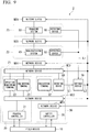
- FIG. 8 is a block diagram illustrating a whole configuration of the integrated industrial system in the second embodiment of the present invention.
- parts that are the same as those in FIG. 1 are assigned the same reference numerals.
- the integrated industrial system 2 of the present embodiment is generally the same configuration as the integrated industrial system 1 shown in FIG. 1 .
- the integrated industrial system 2 of the present embodiment is different from the integrated industrial system 1 shown in FIG.
- the detecting device 60 and the defense device 70 are connected to each other through a communication line L1 (first communication line) which is different from the network (the network configured by the network devices NE1 to NE6), and in that the defense device 70 and the network devices NE1 to NE6 are connected through a communication line L2 (second communication line) which is different from the network.
- L1 first communication line
- L2 second communication line
- the communication line L1 is a transmission line for transmitting a contact signal, and a transmission line for transmitting an analog signal.
- the communication line L1 transmits the detection result detected by the detecting device 60 to the defense device 70.
- the communication line L1 may connect the detecting device 60 and the defense device 70 by one-to-one, or may connect two or more detectors 60 and the defense device 70 in a form of network.
- the communication line L2 is a transmission line for transmitting a contact signal, and a transmission line for transmitting an analog signal.
- the communication line L2 transmits, to the network devices NE1 to NE6, a signal transmitted from the defense device 70 (a signal for performing security countermeasures).
- the communication line L2 may connect the defense device 70 and the network devices NE1 to NE6 by one-to-one, or may connect the defense device 70 and the network devices NE1 to NE6 in a form of network.
- the detecting device 60 and the defense device 70 are connected by the communication line L1
- the defense device 70 and the network devices NE1 to NE6 are connected by the communication line L2, in order to be able to prevent the cyber-attack from outside more certainly. That is, if a cyber-attack is performed, there is a possibility that communication through the network configured by the network devices NE1 to NE6 becomes impossible.
- the detection result of the detecting device 60 can be transmitted to the defense device 70, and the security countermeasures (for example, a countermeasure of restricting a communication between the zones Z1 to Z3, or a countermeasure of restricting a communication in the zone Z1) can be performed by the defense device 70. For this reason, the cyber-attack from outside can be prevented more certainly.
- the security countermeasures for example, a countermeasure of restricting a communication between the zones Z1 to Z3, or a countermeasure of restricting a communication in the zone Z1
- the integrated industrial system 2 of the present embodiment is the same as the integrated industrial system 1 of the first embodiment, except that the detection result of the detecting device 60 is transmitted to the defense device 70 through the communication line L1, and except that the signal from the defense device 70 (signal for performing a security countermeasure) is transmitted to the network devices NE1 to NE6 through the communication line L2. For this reason, since operations of the integrated industrial system 2 of the present embodiment are basically the same as those of the integrated industrial system 1 of the first embodiment, detail explanations will be omitted.
- the detecting device 60 which detects cyber-attacks from outside is installed in each of the zones Z1, Z2, and Z3 in which the safety instrumented system 30, the manufacturing system 40, and the managing system 50 are installed respectively. Moreover, based on the detection result of the detecting device 60, the communication between the zones Z1 to Z3 or the communication in the zone Z1 is restricted by the defense device 70. For this reason, the cyber-attack to the safety instrumented system 30 can be prevented beforehand, and the normality of the safety instrumented system 30 can be secured. Further, by setting countermeasures in accordance with threat of the cyber-attack, the cyber-attack can be prevented effectively without shutting down the plant carelessly.
- FIG. 9 is a block diagram illustrating a whole configuration of the integrated industrial system in the third embodiment of the present invention.
- the integrated industrial system 3 of the present embodiment is generally the same configuration as the integrated industrial system 2 shown in FIG. 8 .
- the integrated industrial system 3 of the present embodiment is different from the integrated industrial system 2 shown in FIG. 8 in that the defense device 70 is installed in neither of the zones Z1 to Z3 (the defense device 70 belongs to neither of the zones Z1 to Z3).
- the safety instrumented system 30 which plays a role of "stronghold for securing safety" and the defense device 70 which defends the safety instrumented system 30 can be constructed integrally.
- the safety instrumented system 30 and the defense device 70 can be constructed separately, and the flexibility of the construction can be improved.
- the detecting device 60 which detects cyber-attacks from outside is installed in each of the zones Z1, Z2, and Z3 in which the safety instrumented system 30, the manufacturing system 40, and the managing system 50 are installed respectively. Moreover, based on the detection result of the detecting device 60, the communication between the zones Z1 to Z3 or the communication in the zone Z1 is restricted by the defense device 70. For this reason, the cyber-attack to the safety instrumented system 30 can be prevented beforehand, and the normality of the safety instrumented system 30 can be secured. Further, by setting countermeasures in accordance with threat of the cyber-attack, the cyber-attack can be prevented effectively without shutting down the plant carelessly.
- the detecting device 60 and the defense device 70 are connected by the communication line L1, and the defense device 70 and the network devices NE1 to NE6 are connected by the communication line L2. For this reason, even if communication through the network configured by the network devices NE1 to NE6 becomes impossible, the detection result of the detecting device 60 can be transmitted to the defense device 70, and security countermeasures can be performed by the defense device 70. For this reason, the cyber-attack from outside can be prevented more certainly.
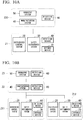
- FIG. 10A and FIG. 10B are block diagrams illustrating the integrated industrial system in the other embodiments of the present invention.
- parts that are the same as those in FIG. 1 , FIG. 8 , and FIG. 9 are assigned the same reference numerals.
- the field device 10 and the network devices NE1 to NE6 are omitted to simplify the illustration.
- the manufacturing system 40 and the managing system 50 are installed in the same zone Z20, and the detecting device 60 is installed in the zone Z20.
- the integrated industrial systems 1 to 3 of the first to third embodiments are sectioned to the zones Z1 to Z3 on a basis of hierarchy, two or more hierarchies may be installed in one zone as the present embodiment.
- the integrated industrial system of the embodiment shown in FIG. 10B is equipped with two or more distributed control systems 20 and two or more safety instrumented systems 30.
- the distributed control system 20, the safety instrumented system 30, the detecting device 60, and the defense device 70 are installed in each of zones Z11 and Z12.
- the safety instrumented system 30 and the defense device 70 are associated with each other, and the defense device 70 operates in order to prevent beforehand the cyber-attack to the associated safety instrumented system 30.
- the defense device 70 is installed in the zone Z1 in which the safety instrumented system 30 is installed, it is not necessary for the defense device 70 to be installed in the zone Z1.
- the defense device 70 may be installed in a zone (the zone Z2 or the zone Z3) which is different from the zone Z1 in which the safety instrumented system 30 is installed.
- the present invention is not restricted to the above-described embodiments, and can be freely modified within the scope thereof.
- the foregoing descriptions of the embodiments have been examples in which the integrated industrial system is sectioned to the zones Z1 to Z3 on a basis of hierarchy specified by International Standard ISA-95 (IEC/ISO 62264), in order to secure security.
- IEC/ISO 62264 International Standard ISA-95
- a zone for security countermeasures can be set arbitrarily, and a zone in which a configuration included in the integrated industrial system is installed can be set arbitrarily.
- the term "configured” is used to describe a component, unit or part of a device includes hardware and/or software that is constructed and/or programmed to carry out the desired function.
- unit is used to describe a component, unit or part of a hardware and/or software that is constructed and/or programmed to carry out the desired function.
- Typical examples of the hardware may include, but are not limited to, a device and a circuit.
Landscapes
- Engineering & Computer Science (AREA)
- Computer Security & Cryptography (AREA)
- Computer Hardware Design (AREA)
- General Engineering & Computer Science (AREA)
- Computer Networks & Wireless Communication (AREA)
- Signal Processing (AREA)
- Computing Systems (AREA)
- General Physics & Mathematics (AREA)
- Physics & Mathematics (AREA)
- Software Systems (AREA)
- Theoretical Computer Science (AREA)
- Health & Medical Sciences (AREA)
- Automation & Control Theory (AREA)
- General Health & Medical Sciences (AREA)
- Medical Informatics (AREA)
- Virology (AREA)
- Computer And Data Communications (AREA)
- Safety Devices In Control Systems (AREA)
Abstract
Description
- The disclosure relates to an integrated industrial system and a control method thereof.
- Priority is claimed on Japanese Patent Application No.
2015-244221, filed December 15,2015 - In a plant and a factory (hereinafter, called simply "plant" as a generic name of them), an integrated industrial system is established, and an advanced automatic operation is implemented. In order to secure safety and perform advanced control, the integrated industrial system includes a control system such as a distributed control system (DCS) and a safety system such as a safety instrumented system (SIS). The distributed control system is a process control system which controls industrial process implemented in the plant.
- In the distributed control system, field devices (for example, a measurement device and an actuation device) and a controller which controls these field devices are connected to each other through communication means. The controller collects measurement data measured by a field device, and operates (controls) a field device in accordance with the collected measurement data. Thereby, the distributed control system controls various kinds of state quantity in the industrial process. In an emergency, the safety instrumented system certainly shuts down the plant in a safe state. Thereby, the safety instrumented system prevents a physical injury and an environmental pollution, and protects expensive facilities. When an abnormal circumstance occurs in the plant, the safety instrumented system plays a role of "stronghold for securing safety".
- There is a possibility that the integrated industrial system receives cyber-attacks from outside. For this reason, in the integrated industrial system, countermeasures (security countermeasures) for a case that each of the distributed control system and the safety instrumented system receives cyber-attacks, or for a case that the whole integrated industrial system receives cyber-attacks, are prepared. For example, a firewall for preventing intrusion from outside to the integrated industrial system is prepared, or antivirus software (software which detects virus infection and removes virus) is installed in a computer. The controller which is a core of the distributed control system and the safety instrumented system has a high resistance against cyber-attacks by using an original operating system.
- The integrated industrial system is sectioned into two or more zones, and the security countermeasures are basically applied to each zone. For example, an integrated industrial system established in conformity with hierarchical structures specified by International Standard ISA-95 (IEC/ISO 62264) is sectioned into two or more zones on the basis of hierarchy. The security countermeasures are applied to each hierarchy.
- For example, a conventional technology for maintaining security of a control network is disclosed in Japanese Unexamined Patent Application Publication No.
2000-267957 2010-081610 2013-161432 - By the way, as described above, since the security countermeasures against cyber-attacks from the outside are basically applied to each zone, the security countermeasures are individually performed in each zone when cyber-attacks are performed. For this reason, in the conventional integrated industrial system, if the security countermeasures of each zone are not enough with respect to cyber-attacks, the cyber-attacks reach the zone where the safety instrumented system belongs. For this reason, there is a problem that final defense countermeasures depend on security countermeasures applied to the zone where the safety instrumented system belongs.
- The safety instrumented system does not usually communicate with a host system, but the safety instrumented system communicates with the distributed control system. On the other hand, the distributed control system is supposed to communicate with the host system. As a result, since the safety instrumented system is connected to the host system, there is a problem that cyber-attacks may reach the zone where the safety instrumented system belongs.
- As described above, if the security countermeasures of each zone are not enough with respect to cyber-attacks, cyber-attacks reach the zone where the safety instrumented system belongs. For this reason, a control right of the safety instrumented system (or an engineering station which creates program to be used by the safety instrumented system) may be deprived. If such a situation occurs and programs of the controller which is a core of the safety instrumented system are rewritten, a role of "stronghold for securing safety" is lost. Therefore, it is necessary not to raise the above-described situation.
- An integrated industrial system may include a safety instrumented system which is installed in a first zone, a host system which is connected to the safety instrumented system through a network, the host system being installed in a second zone which is different from the first zone, a detector which is installed in each of the first zone and the second zone, the detector being configured to detect a cyber-attack from outside to a self-zone, and a defender configured to perform a countermeasure of restricting a communication between the first zone and the second zone or of restricting a communication in the first zone or the second zone, based on a detection result of the detector.
- Further features and aspects of the present disclosure will become apparent from the following detailed description of exemplary embodiments with reference to the attached drawings.
-
-
FIG. 1 is a block diagram illustrating a whole configuration of the integrated industrial system in the first embodiment of the present invention. -
FIG. 2 is a block diagram illustrating a main configuration of the defense device in the first embodiment of the present invention. -
FIG. 3 is a drawing illustrating an example of the setting list in the first embodiment of the present invention. -
FIG. 4A is a drawing illustrating an example of the attack target list in the first embodiment of the present invention. -
FIG. 4B is a drawing illustrating an example of the countermeasure list in the first embodiment of the present invention. -
FIG. 5 is a drawing illustrating another example of the setting list in the first embodiment of the present invention. -
FIG. 6A is a drawing illustrating another example of the attack target list in the first embodiment of the present invention. -
FIG. 6B is a drawing illustrating another example of the countermeasure list in the first embodiment of the present invention. -
FIG. 7 is a flow chart illustrating an operation of the defense device in the first embodiment of the present invention. -
FIG. 8 is a block diagram illustrating a whole configuration of the integrated industrial system in the second embodiment of the present invention. -
FIG. 9 is a block diagram illustrating a whole configuration of the integrated industrial system in the third embodiment of the present invention. -
FIG. 10A is a block diagram illustrating the integrated industrial system in the other embodiments of the present invention. -
FIG. 10B is a block diagram illustrating the integrated industrial system in the other embodiments of the present invention. - The embodiments of the present invention will be now described herein with reference to illustrative preferred embodiments. Those skilled in the art will recognize that many alternative preferred embodiments can be accomplished using the teaching of the present invention and that the present invention is not limited to the preferred embodiments illustrated herein for explanatory purposes.
- An aspect of the present invention is to provide an integrated industrial system and a control method thereof which can defend against cyber-attacks to a safety instrumented system beforehand, and can secure a normality of the safety instrumented system.
- Hereinafter, an integrated industrial system and a control method thereof of embodiments will be described in detail, with reference to drawings.
-
FIG. 1 is a block diagram illustrating a whole configuration of the integrated industrial system in the first embodiment of the present invention. As shown inFIG. 1 , the integratedindustrial system 1 of the present embodiment includes afield device 10, a distributed control system (DCS) 20, a safety instrumented system (SIS) 30, a manufacturing system 40 (a host system; a first system), a managing system 50 (a host system; a second system), a detecting device 60 (detector), and a defense device 70 (defender). The integratedindustrial system 1 performs automatic operation of a plant, and performs maintenance management of the plant. - The integrated
industrial system 1 is established in conformity with hierarchical structures specified by International Standard ISA-95 (IEC/ISO 62264). Specifically, in the integratedindustrial system 1, the distributedcontrol system 20 and the safety instrumentedsystem 30 belong to a hierarchy oflevel 2, themanufacturing system 40 belongs to a hierarchy oflevel 3, and the managingsystem 50 belongs to a hierarchy of level 4. The distributedcontrol system 20, the safety instrumentedsystem 30, themanufacturing system 40, the managingsystem 50, the detectingdevice 60, and thedefense device 70 are connected to each other through a network configured by network devices NE1 to NE6. - The integrated
industrial system 1 is sectioned into two or more zones on the basis of hierarchy in order to prepare security countermeasures. Specifically, in the integratedindustrial system 1, the distributedcontrol system 20 and the safety instrumentedsystem 30 are installed in a zone Z1, themanufacturing system 40 is installed in a zone Z2, and the managingsystem 50 is installed in a zone Z3. - The plant includes an industrial plant such as a chemical industrial plant, a plant managing and controlling a wellhead (for example, a gas field and an oil field), a plant managing and controlling a generation of electric power (for example, hydro power, thermal power, and nuclear power), a plant managing and controlling a power harvesting (for example, solar power and wind power), a plant managing and controlling water supply and sewerage systems, a dam, and so on.
- The
field device 10 is installed at a field of the plant, and the field device performs measurement and actuation required for control of industrial process under control of the distributedcontrol system 20. Specifically, thefield device 10 is such as a sensor device (for example, a pressure meter, a flowmeter, a temperature sensor, a gas sensor, and a vibration sensor), a valve device (for example, a flow control valve and an on-off valve), an actuator device (for example, a fan and a motor), an imaging device (for example, a camera and a video camera recording circumstances and objects in the plant), a sound device (for example, a microphone collecting abnormal noise in the plant, and a speaker generating alarm sound), a position detection device outputting position information of the each device, and other devices. - The
field device 10 communicates with the distributedcontrol system 20 or the safety instrumentedsystem 30. For example, thefield device 10 performs wired communication through a network or a communication bus (not shown), or wireless communication in conformity with industrial wireless communication standards, such as ISA100.11a and WirelessHART (registered trademark), with respect to the distributedcontrol system 20 and the safety instrumentedsystem 30. - The distributed
control system 20 is equipped with aprocess controller 21, anoperation monitoring terminal 22, and anengineering terminal 23. The distributedcontrol system 20 collects measurement data measured by thefield device 10, and operates (controls) thefield device 10 in accordance with the collected measurement data, in order to control various kinds of state quantity. The state quantity controlled by the distributedcontrol system 20 is various kinds of state quantity in the industrial process. For example, the state quantity is pressure, temperature, flow quantity, or the like. - The
process controller 21 is a core of the distributedcontrol system 20. Theprocess controller 21 collects the measurement data from thefield device 10, and operates (controls) thefield device 10. For example, theoperation monitoring terminal 22 is operated by a plant operator, and theoperation monitoring terminal 22 is used for monitoring an operational status of the plant. Theengineering terminal 23 is a terminal used for creating programs to be executed by theprocess controller 21. Theprocess controller 21, theoperation monitoring terminal 22, and theengineering terminal 23 are connected to each other through the network device NE2. For example, if it is not necessary to create the programs to be executed by theprocess controller 21, theengineering terminal 23 may be omitted, or theengineering terminal 23 does not need to be always connected to the network. - The safety instrumented
system 30 is equipped with asafety controller 31 and anengineering terminal 32. In an emergency, the safety instrumentedsystem 30 certainly shuts down the plant in a safe state, in order to prevent a physical injury and an environmental pollution, and protect expensive facilities. When an abnormal circumstance occurs in the plant, the safety instrumented system plays a role of "stronghold for securing safety". - The
safety controller 31 is a core of the safety instrumentedsystem 30. Thesafety controller 31 communicates with thefield device 10 or another safety controller (not shown) and obtains necessary data, in order to determine whether an abnormal circumstance occurs in the plant or not. If thesafety controller 31 determines that an abnormal circumstance occurs in the plant, thesafety controller 31 executes a safety control logic for implementing safety control. Theengineering terminal 32 is a terminal used for creating programs to be executed by thesafety controller 31. Thesafety controllers 31 and theengineering terminal 32 are connected to each other through the network devices NE1 and NE2. Similar to theengineering terminal 23, for example, if it is not necessary to create the programs to be executed by thesafety controller 31, theengineering terminal 32 may be omitted, or theengineering terminal 32 is not always connected to the network. - The
manufacturing system 40 is a system established for manufacturing products in the plant efficiently. Themanufacturing system 40 is such as a Manufacturing Execution System (MES), a Plant Information Management System (PIMS), and a Plant Asset Management System (PAM). As themanufacturing system 40, only one of the Manufacturing Execution System, the Plant Information Management System, and the Plant Asset Management System may be established, and two or more of them may be established. Themanufacturing system 40 is connected to the distributedcontrol system 20 and the safety instrumentedsystem 30 through the network devices NE3 and NE4. - The managing
system 50 is a system established for business, such as management or sales and marketing in a company. For example, the managingsystem 50 is an Enterprise Resource Planning System (ERP). The managingsystem 50 is connected to themanufacturing system 40 through the network device NE5, and the managingsystem 50 is connected to other unillustrated networks (for example, Internet) through the network device NE6. - The detecting
device 60 is installed in each of the zones Z1 to Z3. The detectingdevice 60 detects cyber-attacks from outside to the self-zone. The cyber-attacks from outside are such as an unauthorized invasion to the integratedindustrial system 1, an alteration of the program used by the integratedindustrial system 1, a fraud and a destruction of data used by the integratedindustrial system 1, an act for making the integratedindustrial system 1 be in malfunction state, and other acts. - The detecting
device 60 is prepared in accordance with a design concept of each of the zones Z1 to Z3. For example, the detectingdevice 60 can utilize commercial antivirus software (software which detects virus infection and removes virus), or utilize an intrusion detection system. In the present embodiment, in order to understand easily, an example that the detectingdevice 60 is prepared as "device" will be described, but the function of the detectingdevice 60 may be implemented by software. - The detecting
device 60 installed in each of the zones Z1 to Z3 is connected to the network configured by the network devices NE1 to NE6. If the detectingdevice 60 installed in each of the zones Z1 to Z3 detects cyber-attacks, the detectingdevice 60 transmits the detection result to thedefense device 70 through the network. Specifically, the detectingdevice 60 installed in the zone Z1 is connected to the network devices NE2 and NE3. The detectingdevice 60 installed in the zone Z2 is connected to the network devices NE4 and NE5. The detectingdevice 60 installed in the zone Z3 is connected to the network device NE5 and NE6. - The network devices NE1 to NE6 are such as a firewall, a router, a switch, and so on. The network device NE4 is installed between the zone Z1 and the zone Z2. The network device NE5 is installed between the zone Z2 and the zone Z3. The network device NE6 is installed between the zone Z3 and another unillustrated network (for example, Internet). The network device NE1 is installed between the
safety controller 31 and the network device N2. - The
defense device 70 performs security countermeasures for defending against cyber-attacks from outside based on the detection result obtained from the detectingdevice 60. For example, thedefense device 70 performs a countermeasure of restricting a communication between the zones Z1 to Z3, or a countermeasure of restricting a communication in the zone Z1. Thedefense device 70 is installed in the zone Z1 where the safety instrumentedsystem 30 belongs. Thedefense device 70 obtains the detection result of the detectingdevice 60 through the network configured by the network devices NE1 to NE6, and thedefense device 70 performs the security countermeasures through the network configured by the network devices NE1 to NE6. -
FIG. 2 is a block diagram illustrating a main configuration of the defense device in the first embodiment of the present invention. As shown inFIG. 2 , thedefense device 70 is equipped with asetter 71 and anexecutor 72. Thesetter 71 specifies a target and a type of the cyber-attack based on the detection result of the detectingdevice 60, and thesetter 71 sets security countermeasures in accordance with the specified contents. Thesetter 71 sets the security countermeasures by using a setting list LS in which an attack target list and a countermeasure list are associated with each other. The attack target list represents a list of the target and the type of the cyber-attack. The countermeasure list represents a list of security countermeasures which should be performed in accordance with the target and the type of the cyber-attack. Theexecutor 72 executes security countermeasures which have been set by thesetter 71. In the present embodiment, in order to understand easily, an example that thedefense device 70 is prepared as "device" will be described. However, similar to the detectingdevice 60, the function of thedefense device 70 may be implemented by software. -
FIG. 3 is a drawing illustrating an example of the setting list in the first embodiment of the present invention.FIG. 4A is a drawing illustrating an attack target list.FIG. 4B is a drawing illustrating a countermeasure list. As shown inFIG. 3 ,FIG. 4A, and FIG. 4B , the setting list LS is a list in which "attack target number" (attack target No.) of the attack target list, "countermeasure number" (countermeasure No.) of the countermeasure list, and "target device" have been associated with each other. The "target device" is a target to which security countermeasures are to be performed. - As shown in
FIG. 4A , the attack target list is a list in which "attack target number" (attack target No.), "zone", "device", "level", and "type" have been associated with each other. The attack target list is a list used for specifying what kind of attack has been made with respect to which zone. The "attack target number" is a number allocated for distinguishing various cyber-attacks performed to the integratedindustrial system 1. The "zone" is information for specifying a zone to which the cyber-attack has been performed. - The "device" is information for specifying a device to which the cyber-attack has been performed. The "device" is such as a personal computer (PC), a controller, a switch, a firewall, and so on. The "level" is information for specifying which part of a device has been attacked with the cyber-attack. The "level" is such as an operating system (OS), a network, hardware, application, and so on. The "type" is information for specifying a type of the cyber-attack. The "type" is such as a virus, a DoS attack (Denial of Service attack), and so on.
- As shown in
FIG. 4B , a countermeasure list is a list in which "countermeasure number" (countermeasure No.) and "action" have been associated with each other. The "countermeasure number" is a number allocated for distinguishing various security countermeasures performed by the integratedindustrial system 1. The "action" is information for specifying a security countermeasure which should be performed against the cyber-attack if the cyber-attack is performed. The "action" is such as disconnecting the network port logically, blocking the network physically, and so on. - For example, in a fourth line of the setting list LS shown in
FIG. 3 , an attack target number "A4", a countermeasure number "B3", and target devices "NE5, NE6" are associated with each other. Since the association has been made, if a PC which belongs to the zone Z3 has been infected with a virus by a cyber-attack, a security countermeasure of logically disconnecting the network port of the network devices NE5 and NE6 is to be performed. - For example, in an eighth line of the setting list LS shown in
FIG. 3 , an attack target number "A8", a countermeasure number "B5", and target devices "NE1, NE2, NE3" are associated with each other. Since the association has been made, if a PC which belongs to the zone Z1 has been attacked with a cyber-attack, a security countermeasure of blocking power supply of the network devices NE1, NE2, and NE3, and for physically blocking the network, is to be performed. - For example, in a ninth line of the setting list LS shown in
FIG. 3 , an attack target number "A9", a countermeasure number "B2", and target devices "HMI22,ENG -
FIG. 5 is a drawing illustrating another example of the setting list in the first embodiment of the present invention.FIG. 6A is a drawing illustrating another example of the attack target list.FIG. 6B is a drawing illustrating another example of the countermeasure list. Unlike the lists shown inFIG. 3 ,FIG. 4A, and FIG. 4B , the setting list LS shown inFIG. 5 , if a cyber-attack is detected, the attack target list shown inFIG. 6A , and the countermeasure list shown inFIG. 6B are used by an administrator for determining a countermeasure against the cyber-attack without disconnecting the network. - For example, in a third line of the setting list LS shown in
FIG. 5 , an attack target number "A13", a countermeasure number "B13", and target devices "HMI22,ENG - Next, operations of the integrated
industrial system 1 of the above-described configuration will be described. Although operations of the integratedindustrial system 1 are various, operations mainly performed by the detectingdevice 60 and the defense device 70 (operations for detecting a cyber-attack and defending against it) will be described below.FIG. 7 is a flow chart illustrating an operation of the defense device in the first embodiment of the present invention. For example, processing of the flow chart shown inFIG. 7 is performed at a predetermined constant cycle. - If processing of the flow chart shown in
FIG. 7 is started, first, the setter 71 (refer toFIG. 2 ) of thedefense device 70 reads the detection result obtained from the detecting device 60 (Step S11), and thesetter 71 analyzes the detection result (Step S12). Next, thesetter 71 determines whether or not there is a cyber-attack to the integratedindustrial system 1 based on a result of the analysis (Step S13). If thesetter 71 has determined that there is no cyber-attack to the integrated industrial system 1 (Step S13: "NO"), the series of processing shown inFIG. 7 ends. - On the other hand, if the
setter 71 has determined that there is a cyber-attack to the integrated industrial system 1 (Step S13: "YES"), thesetter 71 specifies a target and a type of the cyber-attack based on the result of the analysis performed at Step S12 (Step S14). If thesetter 71 has specified a target and a type of the cyber-attack, thesetter 71 sets a security countermeasure in accordance with the specified contents by using the setting list LS (Step S15). If the security countermeasure is set by thesetter 71, thesetter 71 outputs, to theexecutor 72, information which represents the security countermeasure which has been set. Theexecutor 72 executes the security countermeasure which has been set by the setter 71 (Step S16). - For example, a cyber-attack is performed to a PC used by the managing
system 50 which belongs to the zone Z3, and the PC is infected with a virus. In this case, the virus infection of the PC is detected by the detectingdevice 60 which belongs to the zone Z3. Thesetter 71 of thedefense device 70 reads this detection result (Step S11), and thesetter 71 analyzes it (Step S12). Then, the determination result of Step S13 shown inFIG. 7 is "YES". For this reason, in Step S14, thesetter 71 specifies that the PC which belongs to the zone Z3 has been infected with a virus by the cyber-attack (attack target number "A4"). - If the target and the type of the cyber-attack have been specified, the
setter 71 sets a security countermeasure of logically disconnecting the network port of the network devices NE5 and NE6, based on the countermeasure number "B3" and the target device "NE5, NE6" which are associated with the attack target number "A4" of the fourth line of the setting list LS shown inFIG. 3 (Step S15). Thereafter, theexecutor 72 executes the security countermeasure which has been set by thesetter 71, and the network port of the network devices NE5 and NE6 is disconnected logically (Step S16). By performing the above-described processing, it can be prevented that the PC infected with a virus communicates with devices which belong to other zones (zones Z1 and Z2), and also prevented that the virus infection is expanded. - For example, a cyber-attack is performed to a PC which belongs to the zone Z1. In this case, the cyber-attack to the PC is detected by the detecting
device 60 which belongs to the zone Z1. Thesetter 71 of thedefense device 70 reads this detection result (Step S11), and thesetter 71 analyzes it (Step S12). Then, the determination result of Step S 13 shown inFIG. 7 is "YES". For this reason, in Step S14, thesetter 71 specifies that the PC which belongs to the zone Z1 has been received the cyber-attack (attack target number "A8"). - If the target and the type of the cyber-attack have been specified, the
setter 71 sets a security countermeasure of blocking power supply of the network devices NE1, NE2, and NE3, and for physically blocking the network, based on the countermeasure number "B5" and the target device "NE1, NE2, NE3" which are associated with the attack target number "A8" of the eighth line of the setting list LS shown inFIG. 3 (Step S15). Thereafter, theexecutor 72 executes the security countermeasure which has been set by thesetter 71, the power supply of the network devices NE1, NE2, and NE3 are blocked, and the network is physically blocked in the zone Z1 (Step S16). - By performing the above-described processing, the PC which has been received the cyber-attack and the
safety controller 31 which is a core of the safety instrumentedsystem 30 are physically separated from each other in the zone Z1. Thereby, the cyber-attack to thesafety controller 31 and the safety instrumentedsystem 30 can be prevented beforehand, and the normality of the safety instrumentedsystem 30 can be secured. For this reason, the role of "stronghold for securing safety" is not lost. - As described above, in the present embodiment, the detecting
device 60 which detects cyber-attacks from outside is installed in each of the zones Z1, Z2, and Z3 in which the safety instrumentedsystem 30, themanufacturing system 40, and the managingsystem 50 are installed respectively. Moreover, based on the detection result of the detectingdevice 60, the communication between the zones Z1 to Z3 or the communication in the zone Z1 is restricted by thedefense device 70. For this reason, the cyber-attack to the safety instrumentedsystem 30 can be prevented beforehand, and the normality of the safety instrumentedsystem 30 can be secured. Further, by setting countermeasures in accordance with threat of the cyber-attack, the cyber-attack can be prevented effectively without shutting down the plant carelessly. -
FIG. 8 is a block diagram illustrating a whole configuration of the integrated industrial system in the second embodiment of the present invention. InFIG. 8 , parts that are the same as those inFIG. 1 (or parts that correspond to those inFIG. 1 ) are assigned the same reference numerals. As shown inFIG. 8 , the integratedindustrial system 2 of the present embodiment is generally the same configuration as the integratedindustrial system 1 shown inFIG. 1 . However, the integratedindustrial system 2 of the present embodiment is different from the integratedindustrial system 1 shown inFIG. 1 in that the detectingdevice 60 and thedefense device 70 are connected to each other through a communication line L1 (first communication line) which is different from the network (the network configured by the network devices NE1 to NE6), and in that thedefense device 70 and the network devices NE1 to NE6 are connected through a communication line L2 (second communication line) which is different from the network. - For example, the communication line L1 is a transmission line for transmitting a contact signal, and a transmission line for transmitting an analog signal. The communication line L1 transmits the detection result detected by the detecting
device 60 to thedefense device 70. The communication line L1 may connect the detectingdevice 60 and thedefense device 70 by one-to-one, or may connect two ormore detectors 60 and thedefense device 70 in a form of network. - For example, similar to the communication line L1, the communication line L2 is a transmission line for transmitting a contact signal, and a transmission line for transmitting an analog signal. The communication line L2 transmits, to the network devices NE1 to NE6, a signal transmitted from the defense device 70 (a signal for performing security countermeasures). Similar to the communication line L1, the communication line L2 may connect the
defense device 70 and the network devices NE1 to NE6 by one-to-one, or may connect thedefense device 70 and the network devices NE1 to NE6 in a form of network. - In this way, the detecting
device 60 and thedefense device 70 are connected by the communication line L1, and thedefense device 70 and the network devices NE1 to NE6 are connected by the communication line L2, in order to be able to prevent the cyber-attack from outside more certainly. That is, if a cyber-attack is performed, there is a possibility that communication through the network configured by the network devices NE1 to NE6 becomes impossible. Even if the communication through the network becomes impossible, in a case that the communication through the communication line L1 and the communication line L2 is possible, the detection result of the detectingdevice 60 can be transmitted to thedefense device 70, and the security countermeasures (for example, a countermeasure of restricting a communication between the zones Z1 to Z3, or a countermeasure of restricting a communication in the zone Z1) can be performed by thedefense device 70. For this reason, the cyber-attack from outside can be prevented more certainly. - The integrated
industrial system 2 of the present embodiment is the same as the integratedindustrial system 1 of the first embodiment, except that the detection result of the detectingdevice 60 is transmitted to thedefense device 70 through the communication line L1, and except that the signal from the defense device 70 (signal for performing a security countermeasure) is transmitted to the network devices NE1 to NE6 through the communication line L2. For this reason, since operations of the integratedindustrial system 2 of the present embodiment are basically the same as those of the integratedindustrial system 1 of the first embodiment, detail explanations will be omitted. - As described above, also in the present embodiment, similar to the first embodiment, the detecting
device 60 which detects cyber-attacks from outside is installed in each of the zones Z1, Z2, and Z3 in which the safety instrumentedsystem 30, themanufacturing system 40, and the managingsystem 50 are installed respectively. Moreover, based on the detection result of the detectingdevice 60, the communication between the zones Z1 to Z3 or the communication in the zone Z1 is restricted by thedefense device 70. For this reason, the cyber-attack to the safety instrumentedsystem 30 can be prevented beforehand, and the normality of the safety instrumentedsystem 30 can be secured. Further, by setting countermeasures in accordance with threat of the cyber-attack, the cyber-attack can be prevented effectively without shutting down the plant carelessly. -
FIG. 9 is a block diagram illustrating a whole configuration of the integrated industrial system in the third embodiment of the present invention. InFIG. 9 , parts that are the same as those inFIG. 1 andFIG. 8 (or parts that correspond to those inFIG. 1 andFIG. 8 ) are assigned the same reference numerals. As shown inFIG. 9 , the integratedindustrial system 3 of the present embodiment is generally the same configuration as the integratedindustrial system 2 shown inFIG. 8 . However, the integratedindustrial system 3 of the present embodiment is different from the integratedindustrial system 2 shown inFIG. 8 in that thedefense device 70 is installed in neither of the zones Z1 to Z3 (thedefense device 70 belongs to neither of the zones Z1 to Z3). - If the
defense device 70 is installed in the zone Z1 in which the safety instrumentedsystem 30 is installed like the integratedindustrial system 2 shown inFIG. 8 , the safety instrumentedsystem 30 which plays a role of "stronghold for securing safety" and thedefense device 70 which defends the safety instrumentedsystem 30 can be constructed integrally. On the other hand, in the integratedindustrial system 3 of the present embodiment, the safety instrumentedsystem 30 and thedefense device 70 can be constructed separately, and the flexibility of the construction can be improved. - In the present embodiment, similar to the first and second embodiments, the detecting
device 60 which detects cyber-attacks from outside is installed in each of the zones Z1, Z2, and Z3 in which the safety instrumentedsystem 30, themanufacturing system 40, and the managingsystem 50 are installed respectively. Moreover, based on the detection result of the detectingdevice 60, the communication between the zones Z1 to Z3 or the communication in the zone Z1 is restricted by thedefense device 70. For this reason, the cyber-attack to the safety instrumentedsystem 30 can be prevented beforehand, and the normality of the safety instrumentedsystem 30 can be secured. Further, by setting countermeasures in accordance with threat of the cyber-attack, the cyber-attack can be prevented effectively without shutting down the plant carelessly. - In the present embodiment, similar to the second embodiment, the detecting
device 60 and thedefense device 70 are connected by the communication line L1, and thedefense device 70 and the network devices NE1 to NE6 are connected by the communication line L2. For this reason, even if communication through the network configured by the network devices NE1 to NE6 becomes impossible, the detection result of the detectingdevice 60 can be transmitted to thedefense device 70, and security countermeasures can be performed by thedefense device 70. For this reason, the cyber-attack from outside can be prevented more certainly. -
FIG. 10A and FIG. 10B are block diagrams illustrating the integrated industrial system in the other embodiments of the present invention. InFIG. 10A and 10B , parts that are the same as those inFIG. 1 ,FIG. 8 , andFIG. 9 (or parts that correspond to those inFIG. 1 ,FIG. 8 , andFIG. 9 ) are assigned the same reference numerals. InFIG. 10A and FIG. 10B , thefield device 10 and the network devices NE1 to NE6 are omitted to simplify the illustration. - In the integrated industrial system of the embodiment shown in
FIG. 10A , themanufacturing system 40 and the managingsystem 50 are installed in the same zone Z20, and the detectingdevice 60 is installed in the zone Z20. Although the integratedindustrial systems 1 to 3 of the first to third embodiments are sectioned to the zones Z1 to Z3 on a basis of hierarchy, two or more hierarchies may be installed in one zone as the present embodiment. - The integrated industrial system of the embodiment shown in
FIG. 10B is equipped with two or more distributedcontrol systems 20 and two or more safety instrumentedsystems 30. In the integrated industrial system of this form, the distributedcontrol system 20, the safety instrumentedsystem 30, the detectingdevice 60, and thedefense device 70 are installed in each of zones Z11 and Z12. In the integrated industrial system shown inFIG. 10B , the safety instrumentedsystem 30 and thedefense device 70 are associated with each other, and thedefense device 70 operates in order to prevent beforehand the cyber-attack to the associated safety instrumentedsystem 30. - In the second embodiment described above, although the
defense device 70 is installed in the zone Z1 in which the safety instrumentedsystem 30 is installed, it is not necessary for thedefense device 70 to be installed in the zone Z1. For example, thedefense device 70 may be installed in a zone (the zone Z2 or the zone Z3) which is different from the zone Z1 in which the safety instrumentedsystem 30 is installed. - Although an integrated industrial system and a control method thereof according to embodiments of the present invention have been described above, the present invention is not restricted to the above-described embodiments, and can be freely modified within the scope thereof. For example, the foregoing descriptions of the embodiments have been examples in which the integrated industrial system is sectioned to the zones Z1 to Z3 on a basis of hierarchy specified by International Standard ISA-95 (IEC/ISO 62264), in order to secure security. However, it is not necessary for the integrated industrial system to be configured in conformity with the standard. As shown in the examples of
FIG. 10A and FIG. 10B , a zone for security countermeasures can be set arbitrarily, and a zone in which a configuration included in the integrated industrial system is installed can be set arbitrarily. - In the embodiment described above, in order to understand easily, an example of defending the cyber-attack to the safety instrumented
system 30 has been described. However, in addition to the safety instrumentedsystem 30, security countermeasures may be performed in consideration of an influence on the distributedcontrol system 20. - As used herein, the following directional terms "front, back, above, downward, right, left, vertical, horizontal, below, transverse, row and column" as well as any other similar directional terms refer to those instructions of a device equipped with the present invention. Accordingly, these terms, as utilized to describe the present invention should be interpreted relative to a device equipped with the present invention.
- The term "configured" is used to describe a component, unit or part of a device includes hardware and/or software that is constructed and/or programmed to carry out the desired function.
- Moreover, terms that are expressed as "means-plus function" in the claims should include any structure that can be utilized to carry out the function of that part of the present invention.
- The term "unit" is used to describe a component, unit or part of a hardware and/or software that is constructed and/or programmed to carry out the desired function. Typical examples of the hardware may include, but are not limited to, a device and a circuit.
- While preferred embodiments of the present invention have been described and illustrated above, it should be understood that these are examples of the present invention and are not to be considered as limiting. Additions, omissions, substitutions, and other modifications can be made without departing from the scope of the present invention. Accordingly, the present invention is not to be considered as being limited by the foregoing description, and is only limited by the scope of the claims.
Claims (15)
- An integrated industrial system comprising:a safety instrumented system which is installed in a first zone;a host system which is connected to the safety instrumented system through a network, the host system being installed in a second zone which is different from the first zone;a detector which is installed in each of the first zone and the second zone, the detector being configured to detect a cyber-attack from outside to a self-zone; anda defender configured to perform a countermeasure of restricting a communication between the first zone and the second zone or of restricting a communication in the first zone or the second zone, based on a detection result of the detector.
- The integrated industrial system according to claim 1,
wherein the defender further comprises:a setter configured to specify a target and a type of the cyber-attack based on the detection result of the detector, the setter being configured to set the countermeasure in accordance with the target and the type which have been specified; andan executer configured to execute the countermeasure which has been set by the setter. - The integrated industrial system according to claim 2,
wherein the setter is configured to set the countermeasure by using a setting list in which the target and the type of the cyber-attack are associated with the countermeasure which should be performed in accordance with the target and the type of the cyber-attack. - The integrated industrial system according to any one of claims 1 to 3,
wherein the defender is installed in the first zone in which the safety instrumented system is installed,
wherein the defender is configured to obtain the detection result of the detector through the network, and
wherein the defender is configured to perform the countermeasure through the network. - The integrated industrial system according to any one of claims 1 to 3,
wherein the defender is configured to obtain the detection result of the detector through a first communication line which is different from the network, and
wherein the defender is configured to perform the countermeasure through a second communication line which is different from the network. - The integrated industrial system according to claim 5,
wherein the defender is installed in the first zone or the second zone, or in neither the first zone nor the second zone. - The integrated industrial system according to any one of claims 1 to 6,
wherein the host system is a first system which includes at least one of a manufacturing execution system, a plant information management system, and a plant asset management system. - The integrated industrial system according to claim 7, further comprising:a second system which is installed in a third zone which is different from the second zone in which the first system is installed, the second system comprising an enterprise resource planning system.
- The integrated industrial system according to any one of claims 1 to 8, further comprising:a distributed control system which is installed in the first zone in which the safety instrumented system is installed, the distributed control system being configured to control industrial process implemented in a plant.
- The integrated industrial system according to claim 9,
wherein the integrated industrial system is sectioned into two or more zones, and
wherein each of the two or more zones includes the distributed control system, the safety instrumented system, the detector, and the defender. - An integrated industrial system comprising:a first zone which comprises:a safety instrumented system; anda first detector configured to detect a cyber-attack from outside to the first zone;a second zone which comprises:a host system which is connected to the safety instrumented system through a network; anda second detector configured to detect a cyber-attack from outside to the second zone; anda defender configured to restrict a communication between the first zone and the second zone or restrict a communication in the first zone or the second zone, based on a detection result of the first detector and the second detector.
- The integrated industrial system according to claim 11,
wherein the defender further comprises:a setter configured to specify a target and a type of the cyber-attack based on the detection result of the first detector and the second detector, the setter being configured to set a countermeasure in accordance with the target and the type which have been specified; andan executer configured to execute the countermeasure which has been set by the setter. - The integrated industrial system according to claim 12,
wherein the setter is configured to set the countermeasure by using a setting list in which the target and the type of the cyber-attack are associated with the countermeasure which should be performed in accordance with the target and the type of the cyber-attack. - The integrated industrial system according to any one of claims 11 to 13,
wherein the defender is installed in the first zone in which the safety instrumented system is installed,
wherein the defender is configured to obtain the detection result of the first detector and the second detector through the network, and
wherein the defender is configured to perform the countermeasure through the network. - A control method of an integrated industrial system which comprises a safety instrumented system which is installed in a first zone, and a host system which is connected to the safety instrumented system through a network, the host system being installed in a second zone which is different from the first zone, the control method comprising:detecting, by a detector, a cyber-attack from outside to a self-zone, the detector being installed in each of the first zone and the second zone; andperforming, by a defender, a countermeasure of restricting a communication between the first zone and the second zone or of restricting a communication in the first zone or the second zone, based on a detection result of the detector.
Applications Claiming Priority (1)
| Application Number | Priority Date | Filing Date | Title |
|---|---|---|---|
| JP2015244221A JP6759572B2 (en) | 2015-12-15 | 2015-12-15 | Integrated production system |
Publications (2)
| Publication Number | Publication Date |
|---|---|
| EP3182669A1 true EP3182669A1 (en) | 2017-06-21 |
| EP3182669B1 EP3182669B1 (en) | 2018-12-12 |
Family
ID=57838112
Family Applications (1)
| Application Number | Title | Priority Date | Filing Date |
|---|---|---|---|
| EP16203442.5A Active EP3182669B1 (en) | 2015-12-15 | 2016-12-12 | Integrated industrial system and control method thereof |
Country Status (4)
| Country | Link |
|---|---|
| US (1) | US10819742B2 (en) |
| EP (1) | EP3182669B1 (en) |
| JP (1) | JP6759572B2 (en) |
| CN (1) | CN106886716B (en) |
Families Citing this family (9)
| Publication number | Priority date | Publication date | Assignee | Title |
|---|---|---|---|---|
| US11487262B2 (en) * | 2017-11-15 | 2022-11-01 | KSB SE & Co. KGaA | Method and apparatus for protecting pump units from cyber attacks |
| US11297563B2 (en) | 2017-12-18 | 2022-04-05 | Nec Corporation | Communication apparatus, communication system, communication control method, and program |
| US10728282B2 (en) | 2018-01-19 | 2020-07-28 | General Electric Company | Dynamic concurrent learning method to neutralize cyber attacks and faults for industrial asset monitoring nodes |
| US10663929B2 (en) * | 2018-03-20 | 2020-05-26 | Fisher-Rosemount Systems, Inc. | Long-haul safety system trips |
| WO2019198137A1 (en) * | 2018-04-10 | 2019-10-17 | 三菱電機株式会社 | Security device and built-in device |
| US11627151B2 (en) * | 2018-10-31 | 2023-04-11 | General Electric Company | Industrial asset cyber-attack detection algorithm verification using secure, distributed ledger |
| JP2020095672A (en) * | 2018-11-28 | 2020-06-18 | オムロン株式会社 | Controller system |
| JP7016837B2 (en) * | 2019-06-20 | 2022-02-07 | オムロン株式会社 | Controller system |
| US11969882B2 (en) * | 2019-11-21 | 2024-04-30 | The Raymond Corporation | Material handling vehicle behavior modification based on task classification |
Citations (7)
| Publication number | Priority date | Publication date | Assignee | Title |
|---|---|---|---|---|
| JP2000267957A (en) | 1999-03-16 | 2000-09-29 | Hitachi Ltd | Control system firewall |
| EP1645926A1 (en) * | 2004-09-30 | 2006-04-12 | Rockwell Automation Technologies, Inc. | Scalable and flexible information security achitecture for industrial automation |
| JP2010081610A (en) | 2008-09-25 | 2010-04-08 | Fisher Rosemount Syst Inc | Method and apparatus for secure communication of process control data |
| US20100287608A1 (en) * | 2004-03-01 | 2010-11-11 | Invensys Systems, Inc. | Process control methods and apparatus for intrusion detection, protection and network hardening |
| JP2013161432A (en) | 2012-02-08 | 2013-08-19 | Yokogawa Electric Corp | Display method and display device of plant information |
| EP2775685A1 (en) * | 2013-03-06 | 2014-09-10 | ABB Research Ltd. | Security zones in industrial control systems |
| WO2015092817A1 (en) * | 2013-12-20 | 2015-06-25 | Cyient Limited | A system and method for securing an industrial control system |
Family Cites Families (65)
| Publication number | Priority date | Publication date | Assignee | Title |
|---|---|---|---|---|
| JP2002330177A (en) | 2001-03-02 | 2002-11-15 | Seer Insight Security Inc | Security management server and host sever operating in linkage with the security management server |
| JP2003288282A (en) * | 2002-03-28 | 2003-10-10 | Fujitsu Ltd | Unauthorized access prevention program |
| US9565275B2 (en) | 2012-02-09 | 2017-02-07 | Rockwell Automation Technologies, Inc. | Transformation of industrial data into useful cloud information |
| DE10235794A1 (en) | 2002-08-05 | 2004-03-04 | Siemens Ag | System and procedure for condition-based maintenance |
| US9009084B2 (en) | 2002-10-21 | 2015-04-14 | Rockwell Automation Technologies, Inc. | System and methodology providing automation security analysis and network intrusion protection in an industrial environment |
| AU2003273085A1 (en) | 2002-10-22 | 2004-05-13 | Unho Choi | Integrated emergency response system in information infrastructure and operating method therefor |
| US7467018B1 (en) | 2002-11-18 | 2008-12-16 | Rockwell Automation Technologies, Inc. | Embedded database systems and methods in an industrial controller environment |
| US9503470B2 (en) | 2002-12-24 | 2016-11-22 | Fred Herz Patents, LLC | Distributed agent based model for security monitoring and response |
| US7596807B2 (en) * | 2003-07-03 | 2009-09-29 | Arbor Networks, Inc. | Method and system for reducing scope of self-propagating attack code in network |
| US20050050346A1 (en) | 2003-08-28 | 2005-03-03 | Felactu Odessa John | Dynamic comprehensive global enterprise defensive security system |
| WO2006031302A2 (en) | 2004-07-29 | 2006-03-23 | Intelli7, Inc. | System and method of characterizing and managing electronic traffic |
| DE102005063052A1 (en) | 2005-12-29 | 2007-07-05 | Endress + Hauser Process Solutions Ag | Method for protecting field devices of process automation technology |
| US7966659B1 (en) | 2006-04-18 | 2011-06-21 | Rockwell Automation Technologies, Inc. | Distributed learn mode for configuring a firewall, security authority, intrusion detection/prevention devices, and the like |
| US20080016339A1 (en) | 2006-06-29 | 2008-01-17 | Jayant Shukla | Application Sandbox to Detect, Remove, and Prevent Malware |
| US20120284790A1 (en) | 2006-09-11 | 2012-11-08 | Decision-Zone Inc. | Live service anomaly detection system for providing cyber protection for the electric grid |
| US20080125887A1 (en) | 2006-09-27 | 2008-05-29 | Rockwell Automation Technologies, Inc. | Event context data and aggregation for industrial control systems |
| US7881869B2 (en) | 2006-12-29 | 2011-02-01 | Schlumberger Technology Corporation | Method and apparatus for evaluating data associated with an offshore energy platform |
| US20090089325A1 (en) | 2007-09-28 | 2009-04-02 | Rockwell Automation Technologies, Inc. | Targeted resource allocation |
| US8881288B1 (en) | 2008-10-28 | 2014-11-04 | Intelligent Automation, Inc. | Graphical models for cyber security analysis in enterprise networks |
| US8413241B2 (en) | 2009-09-17 | 2013-04-02 | Oracle America, Inc. | Integrated intrusion deflection, detection and introspection |
| EP2299650A1 (en) * | 2009-09-21 | 2011-03-23 | Siemens Aktiengesellschaft | Method for recognising anomalies in a control network |
| US8779921B1 (en) * | 2010-05-14 | 2014-07-15 | Solio Security, Inc. | Adaptive security network, sensor node and method for detecting anomalous events in a security network |
| US20110289588A1 (en) | 2010-05-20 | 2011-11-24 | Anupam Sahai | Unification of security monitoring and IT-GRC |
| KR101519623B1 (en) | 2010-12-13 | 2015-05-12 | 한국전자통신연구원 | DDoS detection apparatus and method, DDoS detection and prevention apparatus for reducing positive false |
| JP5689333B2 (en) | 2011-02-15 | 2015-03-25 | インターナショナル・ビジネス・マシーンズ・コーポレーションInternational Business Machines Corporation | Abnormality detection system, abnormality detection device, abnormality detection method, program, and recording medium |
| US9529690B2 (en) | 2011-03-28 | 2016-12-27 | International Business Machines Corporation | Anomaly detection system, anomaly detection method, and program for the same |
| CA2836798A1 (en) | 2011-06-05 | 2012-12-13 | Core Sdi Incorporated | System and method for providing automated computer security compromise as a service |
| US8970349B2 (en) * | 2011-06-13 | 2015-03-03 | Tyco Integrated Security, LLC | System to provide a security technology and management portal |
| US9298917B2 (en) | 2011-09-27 | 2016-03-29 | Redwall Technologies, Llc | Enhanced security SCADA systems and methods |
| US8793790B2 (en) | 2011-10-11 | 2014-07-29 | Honeywell International Inc. | System and method for insider threat detection |
| US9477936B2 (en) | 2012-02-09 | 2016-10-25 | Rockwell Automation Technologies, Inc. | Cloud-based operator interface for industrial automation |
| US8812466B2 (en) | 2012-02-10 | 2014-08-19 | International Business Machines Corporation | Detecting and combating attack in protection system of an industrial control system |
| US20130212668A1 (en) | 2012-02-13 | 2013-08-15 | International Business Machines Corporation | Suspension of Processes in Industrial Control System When an Anomaly Occurs |
| US9110101B2 (en) | 2012-02-17 | 2015-08-18 | Vencore Labs, Inc. | Method and system for packet acquisition, analysis and intrusion detection in field area networks |
| US9360864B2 (en) | 2012-04-11 | 2016-06-07 | General Electric Company | Turbine fault prediction |
| US9661003B2 (en) | 2012-05-11 | 2017-05-23 | Thomas W. Parker | System and method for forensic cyber adversary profiling, attribution and attack identification |
| US9648029B2 (en) | 2012-07-30 | 2017-05-09 | Newegg Inc. | System and method of active remediation and passive protection against cyber attacks |
| CA2889685C (en) | 2013-01-08 | 2018-12-11 | Secure-Nok As | Method, device, and computer program for monitoring an industrial control system |
| KR101394424B1 (en) | 2013-04-22 | 2014-05-13 | 한국인터넷진흥원 | Hypervisor-based intrusion prevention platform and virtual network intrusion prevention system |
| US10026049B2 (en) | 2013-05-09 | 2018-07-17 | Rockwell Automation Technologies, Inc. | Risk assessment for industrial systems using big data |
| WO2015001594A1 (en) * | 2013-07-01 | 2015-01-08 | 株式会社日立製作所 | Control system, control method, and controller |
| US9160761B2 (en) | 2013-07-31 | 2015-10-13 | Hewlett-Packard Development Company, L.P. | Selection of a countermeasure |
| US20160330225A1 (en) | 2014-01-13 | 2016-11-10 | Brightsource Industries (Israel) Ltd. | Systems, Methods, and Devices for Detecting Anomalies in an Industrial Control System |
| US9886581B2 (en) | 2014-02-25 | 2018-02-06 | Accenture Global Solutions Limited | Automated intelligence graph construction and countermeasure deployment |
| US9838476B2 (en) | 2014-03-26 | 2017-12-05 | Rockwell Automation Technologies, Inc. | On-premise data collection and ingestion using industrial cloud agents |
| US20150281278A1 (en) | 2014-03-28 | 2015-10-01 | Southern California Edison | System For Securing Electric Power Grid Operations From Cyber-Attack |
| KR20160002058A (en) | 2014-06-30 | 2016-01-07 | 한국전자통신연구원 | Modbus Communication Pattern Learning Based Abnormal Traffic Detection Apparatus and Method |
| US9680855B2 (en) | 2014-06-30 | 2017-06-13 | Neo Prime, LLC | Probabilistic model for cyber risk forecasting |
| US9800592B2 (en) | 2014-08-04 | 2017-10-24 | Microsoft Technology Licensing, Llc | Data center architecture that supports attack detection and mitigation |
| US9930058B2 (en) | 2014-08-13 | 2018-03-27 | Honeywell International Inc. | Analyzing cyber-security risks in an industrial control environment |
| KR102475945B1 (en) | 2014-09-14 | 2022-12-09 | 크라운 이큅먼트 코포레이션 | Dynamic industrial vehicle measure |
| US9660994B2 (en) | 2014-09-30 | 2017-05-23 | Schneider Electric USA, Inc. | SCADA intrusion detection systems |
| WO2016064919A1 (en) | 2014-10-21 | 2016-04-28 | Abramowitz Marc Lauren | Dynamic security rating for cyber insurance products |
| US9836990B2 (en) | 2014-12-15 | 2017-12-05 | The Boeing Company | System and method for evaluating cyber-attacks on aircraft |
| WO2016125837A1 (en) | 2015-02-04 | 2016-08-11 | 日本電信電話株式会社 | Malicious communication pattern extraction device, malicious communication pattern extraction system, malicious communication pattern extraction method and malicious communication pattern extraction program |
| US10021125B2 (en) | 2015-02-06 | 2018-07-10 | Honeywell International Inc. | Infrastructure monitoring tool for collecting industrial process control and automation system risk data |
| US10291506B2 (en) | 2015-03-04 | 2019-05-14 | Fisher-Rosemount Systems, Inc. | Anomaly detection in industrial communications networks |
| EP3065076A1 (en) | 2015-03-04 | 2016-09-07 | Secure-Nok AS | System and method for responding to a cyber-attack-related incident against an industrial control system |
| US10686828B2 (en) | 2015-04-17 | 2020-06-16 | Soltra Solutions, Llc | Computerized system and method for securely distributing and exchanging cyber-threat information in a standardized format |
| US9892261B2 (en) | 2015-04-28 | 2018-02-13 | Fireeye, Inc. | Computer imposed countermeasures driven by malware lineage |
| US10104107B2 (en) | 2015-05-11 | 2018-10-16 | Qualcomm Incorporated | Methods and systems for behavior-specific actuation for real-time whitelisting |
| US11363035B2 (en) | 2015-05-22 | 2022-06-14 | Fisher-Rosemount Systems, Inc. | Configurable robustness agent in a plant security system |
| US10021115B2 (en) | 2015-11-03 | 2018-07-10 | Juniper Networks, Inc. | Integrated security system having rule optimization |
| US10146936B1 (en) | 2015-11-12 | 2018-12-04 | EMC IP Holding Company LLC | Intrusion detection for storage resources provisioned to containers in multi-tenant environments |
| US10812517B2 (en) * | 2016-06-03 | 2020-10-20 | Honeywell International Inc. | System and method for bridging cyber-security threat intelligence into a protected system using secure media |
-
2015
- 2015-12-15 JP JP2015244221A patent/JP6759572B2/en active Active
-
2016
- 2016-12-09 US US15/373,601 patent/US10819742B2/en active Active
- 2016-12-12 EP EP16203442.5A patent/EP3182669B1/en active Active
- 2016-12-13 CN CN201611149511.5A patent/CN106886716B/en active Active
Patent Citations (7)
| Publication number | Priority date | Publication date | Assignee | Title |
|---|---|---|---|---|
| JP2000267957A (en) | 1999-03-16 | 2000-09-29 | Hitachi Ltd | Control system firewall |
| US20100287608A1 (en) * | 2004-03-01 | 2010-11-11 | Invensys Systems, Inc. | Process control methods and apparatus for intrusion detection, protection and network hardening |
| EP1645926A1 (en) * | 2004-09-30 | 2006-04-12 | Rockwell Automation Technologies, Inc. | Scalable and flexible information security achitecture for industrial automation |
| JP2010081610A (en) | 2008-09-25 | 2010-04-08 | Fisher Rosemount Syst Inc | Method and apparatus for secure communication of process control data |
| JP2013161432A (en) | 2012-02-08 | 2013-08-19 | Yokogawa Electric Corp | Display method and display device of plant information |
| EP2775685A1 (en) * | 2013-03-06 | 2014-09-10 | ABB Research Ltd. | Security zones in industrial control systems |
| WO2015092817A1 (en) * | 2013-12-20 | 2015-06-25 | Cyient Limited | A system and method for securing an industrial control system |
Also Published As
| Publication number | Publication date |
|---|---|
| US20170171243A1 (en) | 2017-06-15 |
| US10819742B2 (en) | 2020-10-27 |
| JP6759572B2 (en) | 2020-09-23 |
| CN106886716B (en) | 2021-03-12 |
| CN106886716A (en) | 2017-06-23 |
| EP3182669B1 (en) | 2018-12-12 |
| JP2017111540A (en) | 2017-06-22 |
Similar Documents
| Publication | Publication Date | Title |
|---|---|---|
| EP3182234B1 (en) | Control device, integrated industrial system, and control method thereof | |
| EP3182669B1 (en) | Integrated industrial system and control method thereof | |
| US11818098B2 (en) | Security system, device, and method for protecting control systems | |
| CN106168757B (en) | Configurable robustness agent in a plant safety system | |
| US11093606B2 (en) | System and method for detecting a cyber-attack at SCADA/ICS managed plants | |
| US10698378B2 (en) | Industrial control system smart hardware monitoring | |
| US20160330225A1 (en) | Systems, Methods, and Devices for Detecting Anomalies in an Industrial Control System | |
| EP2866407A1 (en) | Protection of automated control systems | |
| US10530749B1 (en) | Security system, device, and method for operational technology networks | |
| KR101977731B1 (en) | Apparatus and method for detecting anomaly in a controller system | |
| JP2011100443A (en) | Integrated unified threat management for process control system | |
| EP3646561B1 (en) | A threat detection system for industrial controllers | |
| CN106462137A (en) | A system and method for securing an industrial control system | |
| US12549519B2 (en) | Security system, device, and method for protecting control systems | |
| KR101606090B1 (en) | Apparatus and method for protecting network | |
| CN109076071A (en) | Method for checking the equipment of at least one firewall device and for protecting at least one data sink | |
| HK40029112A (en) | A threat detection system for industrial controllers | |
| HK40029112B (en) | A threat detection system for industrial controllers |
Legal Events
| Date | Code | Title | Description |
|---|---|---|---|
| PUAI | Public reference made under article 153(3) epc to a published international application that has entered the european phase |
Free format text: ORIGINAL CODE: 0009012 |
|
| AK | Designated contracting states |
Kind code of ref document: A1 Designated state(s): AL AT BE BG CH CY CZ DE DK EE ES FI FR GB GR HR HU IE IS IT LI LT LU LV MC MK MT NL NO PL PT RO RS SE SI SK SM TR |
|
| AX | Request for extension of the european patent |
Extension state: BA ME |
|
| 17P | Request for examination filed |
Effective date: 20171221 |
|
| RBV | Designated contracting states (corrected) |
Designated state(s): AL AT BE BG CH CY CZ DE DK EE ES FI FR GB GR HR HU IE IS IT LI LT LU LV MC MK MT NL NO PL PT RO RS SE SI SK SM TR |
|
| REG | Reference to a national code |
Ref country code: DE Ref legal event code: R079 Ref document number: 602016008118 Country of ref document: DE Free format text: PREVIOUS MAIN CLASS: H04L0029060000 Ipc: G05B0019048000 |
|
| GRAP | Despatch of communication of intention to grant a patent |
Free format text: ORIGINAL CODE: EPIDOSNIGR1 |
|
| RIC1 | Information provided on ipc code assigned before grant |
Ipc: G05B 19/048 20060101AFI20180605BHEP Ipc: G05B 19/418 20060101ALI20180605BHEP Ipc: H04L 29/08 20060101ALI20180605BHEP Ipc: H04L 29/06 20060101ALI20180605BHEP |
|
| INTG | Intention to grant announced |
Effective date: 20180618 |
|
| GRAS | Grant fee paid |
Free format text: ORIGINAL CODE: EPIDOSNIGR3 |
|
| GRAA | (expected) grant |
Free format text: ORIGINAL CODE: 0009210 |
|
| AK | Designated contracting states |
Kind code of ref document: B1 Designated state(s): AL AT BE BG CH CY CZ DE DK EE ES FI FR GB GR HR HU IE IS IT LI LT LU LV MC MK MT NL NO PL PT RO RS SE SI SK SM TR |
|
| REG | Reference to a national code |
Ref country code: GB Ref legal event code: FG4D |
|
| REG | Reference to a national code |
Ref country code: CH Ref legal event code: EP |
|
| REG | Reference to a national code |
Ref country code: AT Ref legal event code: REF Ref document number: 1076823 Country of ref document: AT Kind code of ref document: T Effective date: 20181215 |
|
| REG | Reference to a national code |
Ref country code: DE Ref legal event code: R096 Ref document number: 602016008118 Country of ref document: DE |
|
| REG | Reference to a national code |
Ref country code: IE Ref legal event code: FG4D |
|
| REG | Reference to a national code |
Ref country code: NL Ref legal event code: MP Effective date: 20181212 |
|
| REG | Reference to a national code |
Ref country code: LT Ref legal event code: MG4D |
|
| PG25 | Lapsed in a contracting state [announced via postgrant information from national office to epo] |
Ref country code: FI Free format text: LAPSE BECAUSE OF FAILURE TO SUBMIT A TRANSLATION OF THE DESCRIPTION OR TO PAY THE FEE WITHIN THE PRESCRIBED TIME-LIMIT Effective date: 20181212 Ref country code: BG Free format text: LAPSE BECAUSE OF FAILURE TO SUBMIT A TRANSLATION OF THE DESCRIPTION OR TO PAY THE FEE WITHIN THE PRESCRIBED TIME-LIMIT Effective date: 20190312 Ref country code: HR Free format text: LAPSE BECAUSE OF FAILURE TO SUBMIT A TRANSLATION OF THE DESCRIPTION OR TO PAY THE FEE WITHIN THE PRESCRIBED TIME-LIMIT Effective date: 20181212 Ref country code: LV Free format text: LAPSE BECAUSE OF FAILURE TO SUBMIT A TRANSLATION OF THE DESCRIPTION OR TO PAY THE FEE WITHIN THE PRESCRIBED TIME-LIMIT Effective date: 20181212 Ref country code: ES Free format text: LAPSE BECAUSE OF FAILURE TO SUBMIT A TRANSLATION OF THE DESCRIPTION OR TO PAY THE FEE WITHIN THE PRESCRIBED TIME-LIMIT Effective date: 20181212 Ref country code: LT Free format text: LAPSE BECAUSE OF FAILURE TO SUBMIT A TRANSLATION OF THE DESCRIPTION OR TO PAY THE FEE WITHIN THE PRESCRIBED TIME-LIMIT Effective date: 20181212 Ref country code: NO Free format text: LAPSE BECAUSE OF FAILURE TO SUBMIT A TRANSLATION OF THE DESCRIPTION OR TO PAY THE FEE WITHIN THE PRESCRIBED TIME-LIMIT Effective date: 20190312 |
|
| REG | Reference to a national code |
Ref country code: AT Ref legal event code: MK05 Ref document number: 1076823 Country of ref document: AT Kind code of ref document: T Effective date: 20181212 |
|
| PG25 | Lapsed in a contracting state [announced via postgrant information from national office to epo] |
Ref country code: AL Free format text: LAPSE BECAUSE OF FAILURE TO SUBMIT A TRANSLATION OF THE DESCRIPTION OR TO PAY THE FEE WITHIN THE PRESCRIBED TIME-LIMIT Effective date: 20181212 Ref country code: GR Free format text: LAPSE BECAUSE OF FAILURE TO SUBMIT A TRANSLATION OF THE DESCRIPTION OR TO PAY THE FEE WITHIN THE PRESCRIBED TIME-LIMIT Effective date: 20190313 Ref country code: RS Free format text: LAPSE BECAUSE OF FAILURE TO SUBMIT A TRANSLATION OF THE DESCRIPTION OR TO PAY THE FEE WITHIN THE PRESCRIBED TIME-LIMIT Effective date: 20181212 Ref country code: SE Free format text: LAPSE BECAUSE OF FAILURE TO SUBMIT A TRANSLATION OF THE DESCRIPTION OR TO PAY THE FEE WITHIN THE PRESCRIBED TIME-LIMIT Effective date: 20181212 |
|
| PG25 | Lapsed in a contracting state [announced via postgrant information from national office to epo] |
Ref country code: NL Free format text: LAPSE BECAUSE OF FAILURE TO SUBMIT A TRANSLATION OF THE DESCRIPTION OR TO PAY THE FEE WITHIN THE PRESCRIBED TIME-LIMIT Effective date: 20181212 |
|
| PG25 | Lapsed in a contracting state [announced via postgrant information from national office to epo] |
Ref country code: IT Free format text: LAPSE BECAUSE OF FAILURE TO SUBMIT A TRANSLATION OF THE DESCRIPTION OR TO PAY THE FEE WITHIN THE PRESCRIBED TIME-LIMIT Effective date: 20181212 Ref country code: CZ Free format text: LAPSE BECAUSE OF FAILURE TO SUBMIT A TRANSLATION OF THE DESCRIPTION OR TO PAY THE FEE WITHIN THE PRESCRIBED TIME-LIMIT Effective date: 20181212 Ref country code: PT Free format text: LAPSE BECAUSE OF FAILURE TO SUBMIT A TRANSLATION OF THE DESCRIPTION OR TO PAY THE FEE WITHIN THE PRESCRIBED TIME-LIMIT Effective date: 20190412 Ref country code: PL Free format text: LAPSE BECAUSE OF FAILURE TO SUBMIT A TRANSLATION OF THE DESCRIPTION OR TO PAY THE FEE WITHIN THE PRESCRIBED TIME-LIMIT Effective date: 20181212 |
|
| PG25 | Lapsed in a contracting state [announced via postgrant information from national office to epo] |
Ref country code: EE Free format text: LAPSE BECAUSE OF FAILURE TO SUBMIT A TRANSLATION OF THE DESCRIPTION OR TO PAY THE FEE WITHIN THE PRESCRIBED TIME-LIMIT Effective date: 20181212 Ref country code: SM Free format text: LAPSE BECAUSE OF FAILURE TO SUBMIT A TRANSLATION OF THE DESCRIPTION OR TO PAY THE FEE WITHIN THE PRESCRIBED TIME-LIMIT Effective date: 20181212 Ref country code: LU Free format text: LAPSE BECAUSE OF NON-PAYMENT OF DUE FEES Effective date: 20181212 Ref country code: SK Free format text: LAPSE BECAUSE OF FAILURE TO SUBMIT A TRANSLATION OF THE DESCRIPTION OR TO PAY THE FEE WITHIN THE PRESCRIBED TIME-LIMIT Effective date: 20181212 Ref country code: IS Free format text: LAPSE BECAUSE OF FAILURE TO SUBMIT A TRANSLATION OF THE DESCRIPTION OR TO PAY THE FEE WITHIN THE PRESCRIBED TIME-LIMIT Effective date: 20190412 Ref country code: RO Free format text: LAPSE BECAUSE OF FAILURE TO SUBMIT A TRANSLATION OF THE DESCRIPTION OR TO PAY THE FEE WITHIN THE PRESCRIBED TIME-LIMIT Effective date: 20181212 |
|
| REG | Reference to a national code |
Ref country code: DE Ref legal event code: R097 Ref document number: 602016008118 Country of ref document: DE |
|
| REG | Reference to a national code |
Ref country code: IE Ref legal event code: MM4A |
|
| REG | Reference to a national code |
Ref country code: BE Ref legal event code: MM Effective date: 20181231 |
|
| PLBE | No opposition filed within time limit |
Free format text: ORIGINAL CODE: 0009261 |
|
| STAA | Information on the status of an ep patent application or granted ep patent |
Free format text: STATUS: NO OPPOSITION FILED WITHIN TIME LIMIT |
|
| PG25 | Lapsed in a contracting state [announced via postgrant information from national office to epo] |
Ref country code: SI Free format text: LAPSE BECAUSE OF FAILURE TO SUBMIT A TRANSLATION OF THE DESCRIPTION OR TO PAY THE FEE WITHIN THE PRESCRIBED TIME-LIMIT Effective date: 20181212 Ref country code: MC Free format text: LAPSE BECAUSE OF FAILURE TO SUBMIT A TRANSLATION OF THE DESCRIPTION OR TO PAY THE FEE WITHIN THE PRESCRIBED TIME-LIMIT Effective date: 20181212 Ref country code: AT Free format text: LAPSE BECAUSE OF FAILURE TO SUBMIT A TRANSLATION OF THE DESCRIPTION OR TO PAY THE FEE WITHIN THE PRESCRIBED TIME-LIMIT Effective date: 20181212 Ref country code: IE Free format text: LAPSE BECAUSE OF NON-PAYMENT OF DUE FEES Effective date: 20181212 Ref country code: DK Free format text: LAPSE BECAUSE OF FAILURE TO SUBMIT A TRANSLATION OF THE DESCRIPTION OR TO PAY THE FEE WITHIN THE PRESCRIBED TIME-LIMIT Effective date: 20181212 |
|
| 26N | No opposition filed |
Effective date: 20190913 |
|
| PG25 | Lapsed in a contracting state [announced via postgrant information from national office to epo] |
Ref country code: BE Free format text: LAPSE BECAUSE OF NON-PAYMENT OF DUE FEES Effective date: 20181231 |
|
| PG25 | Lapsed in a contracting state [announced via postgrant information from national office to epo] |
Ref country code: MT Free format text: LAPSE BECAUSE OF NON-PAYMENT OF DUE FEES Effective date: 20181212 |
|
| PG25 | Lapsed in a contracting state [announced via postgrant information from national office to epo] |
Ref country code: FR Free format text: LAPSE BECAUSE OF NON-PAYMENT OF DUE FEES Effective date: 20190212 |
|
| PG25 | Lapsed in a contracting state [announced via postgrant information from national office to epo] |
Ref country code: TR Free format text: LAPSE BECAUSE OF FAILURE TO SUBMIT A TRANSLATION OF THE DESCRIPTION OR TO PAY THE FEE WITHIN THE PRESCRIBED TIME-LIMIT Effective date: 20181212 |
|
| PG25 | Lapsed in a contracting state [announced via postgrant information from national office to epo] |
Ref country code: CY Free format text: LAPSE BECAUSE OF FAILURE TO SUBMIT A TRANSLATION OF THE DESCRIPTION OR TO PAY THE FEE WITHIN THE PRESCRIBED TIME-LIMIT Effective date: 20181212 Ref country code: MK Free format text: LAPSE BECAUSE OF NON-PAYMENT OF DUE FEES Effective date: 20181212 Ref country code: HU Free format text: LAPSE BECAUSE OF FAILURE TO SUBMIT A TRANSLATION OF THE DESCRIPTION OR TO PAY THE FEE WITHIN THE PRESCRIBED TIME-LIMIT; INVALID AB INITIO Effective date: 20161212 |
|
| REG | Reference to a national code |
Ref country code: CH Ref legal event code: PL |
|
| PG25 | Lapsed in a contracting state [announced via postgrant information from national office to epo] |
Ref country code: CH Free format text: LAPSE BECAUSE OF NON-PAYMENT OF DUE FEES Effective date: 20191231 Ref country code: LI Free format text: LAPSE BECAUSE OF NON-PAYMENT OF DUE FEES Effective date: 20191231 |
|
| GBPC | Gb: european patent ceased through non-payment of renewal fee |
Effective date: 20201212 |
|
| PG25 | Lapsed in a contracting state [announced via postgrant information from national office to epo] |
Ref country code: GB Free format text: LAPSE BECAUSE OF NON-PAYMENT OF DUE FEES Effective date: 20201212 |
|
| P01 | Opt-out of the competence of the unified patent court (upc) registered |
Effective date: 20230603 |
|
| PGFP | Annual fee paid to national office [announced via postgrant information from national office to epo] |
Ref country code: DE Payment date: 20251126 Year of fee payment: 10 |