EP3182525A1 - Contact terminal assembled from at least two parts - Google Patents
Contact terminal assembled from at least two parts Download PDFInfo
- Publication number
- EP3182525A1 EP3182525A1 EP15201399.1A EP15201399A EP3182525A1 EP 3182525 A1 EP3182525 A1 EP 3182525A1 EP 15201399 A EP15201399 A EP 15201399A EP 3182525 A1 EP3182525 A1 EP 3182525A1
- Authority
- EP
- European Patent Office
- Prior art keywords
- contact
- spring
- sleeve
- contact terminal
- base part
- Prior art date
- Legal status (The legal status is an assumption and is not a legal conclusion. Google has not performed a legal analysis and makes no representation as to the accuracy of the status listed.)
- Withdrawn
Links
- 238000000034 method Methods 0.000 claims description 16
- 229910000639 Spring steel Inorganic materials 0.000 claims description 9
- 238000002788 crimping Methods 0.000 claims description 4
- 238000010586 diagram Methods 0.000 description 17
- 238000003780 insertion Methods 0.000 description 14
- 230000037431 insertion Effects 0.000 description 14
- 229910000881 Cu alloy Inorganic materials 0.000 description 10
- 239000000463 material Substances 0.000 description 8
- 230000003014 reinforcing effect Effects 0.000 description 8
- 230000008569 process Effects 0.000 description 7
- 230000009286 beneficial effect Effects 0.000 description 5
- 230000036316 preload Effects 0.000 description 5
- PXHVJJICTQNCMI-UHFFFAOYSA-N Nickel Chemical compound [Ni] PXHVJJICTQNCMI-UHFFFAOYSA-N 0.000 description 4
- 238000003466 welding Methods 0.000 description 4
- 230000008859 change Effects 0.000 description 3
- 238000005304 joining Methods 0.000 description 3
- 230000009467 reduction Effects 0.000 description 3
- 238000012360 testing method Methods 0.000 description 3
- 229910000831 Steel Inorganic materials 0.000 description 2
- 230000008901 benefit Effects 0.000 description 2
- 229910052759 nickel Inorganic materials 0.000 description 2
- 238000005476 soldering Methods 0.000 description 2
- 239000010959 steel Substances 0.000 description 2
- 229910052718 tin Inorganic materials 0.000 description 2
- RYGMFSIKBFXOCR-UHFFFAOYSA-N Copper Chemical compound [Cu] RYGMFSIKBFXOCR-UHFFFAOYSA-N 0.000 description 1
- XUIMIQQOPSSXEZ-UHFFFAOYSA-N Silicon Chemical compound [Si] XUIMIQQOPSSXEZ-UHFFFAOYSA-N 0.000 description 1
- ATJFFYVFTNAWJD-UHFFFAOYSA-N Tin Chemical compound [Sn] ATJFFYVFTNAWJD-UHFFFAOYSA-N 0.000 description 1
- 238000013459 approach Methods 0.000 description 1
- 238000006243 chemical reaction Methods 0.000 description 1
- 229910052804 chromium Inorganic materials 0.000 description 1
- 239000011651 chromium Substances 0.000 description 1
- VNNRSPGTAMTISX-UHFFFAOYSA-N chromium nickel Chemical compound [Cr].[Ni] VNNRSPGTAMTISX-UHFFFAOYSA-N 0.000 description 1
- 239000004020 conductor Substances 0.000 description 1
- 229910052802 copper Inorganic materials 0.000 description 1
- 239000010949 copper Substances 0.000 description 1
- 238000005260 corrosion Methods 0.000 description 1
- 230000007797 corrosion Effects 0.000 description 1
- 230000008878 coupling Effects 0.000 description 1
- 238000010168 coupling process Methods 0.000 description 1
- 238000005859 coupling reaction Methods 0.000 description 1
- 238000013461 design Methods 0.000 description 1
- 239000013013 elastic material Substances 0.000 description 1
- 238000004519 manufacturing process Methods 0.000 description 1
- 230000006855 networking Effects 0.000 description 1
- 230000003287 optical effect Effects 0.000 description 1
- 238000000926 separation method Methods 0.000 description 1
- 230000011664 signaling Effects 0.000 description 1
- 229910052710 silicon Inorganic materials 0.000 description 1
- 239000010703 silicon Substances 0.000 description 1
- JBQYATWDVHIOAR-UHFFFAOYSA-N tellanylidenegermanium Chemical compound [Te]=[Ge] JBQYATWDVHIOAR-UHFFFAOYSA-N 0.000 description 1
- 230000007704 transition Effects 0.000 description 1
- 239000011701 zinc Substances 0.000 description 1
- 229910052725 zinc Inorganic materials 0.000 description 1
Images



Classifications
-
- H—ELECTRICITY
- H01—ELECTRIC ELEMENTS
- H01R—ELECTRICALLY-CONDUCTIVE CONNECTIONS; STRUCTURAL ASSOCIATIONS OF A PLURALITY OF MUTUALLY-INSULATED ELECTRICAL CONNECTING ELEMENTS; COUPLING DEVICES; CURRENT COLLECTORS
- H01R13/00—Details of coupling devices of the kinds covered by groups H01R12/70 or H01R24/00 - H01R33/00
- H01R13/02—Contact members
- H01R13/15—Pins, blades or sockets having separate spring member for producing or increasing contact pressure
- H01R13/18—Pins, blades or sockets having separate spring member for producing or increasing contact pressure with the spring member surrounding the socket
-
- H—ELECTRICITY
- H01—ELECTRIC ELEMENTS
- H01R—ELECTRICALLY-CONDUCTIVE CONNECTIONS; STRUCTURAL ASSOCIATIONS OF A PLURALITY OF MUTUALLY-INSULATED ELECTRICAL CONNECTING ELEMENTS; COUPLING DEVICES; CURRENT COLLECTORS
- H01R13/00—Details of coupling devices of the kinds covered by groups H01R12/70 or H01R24/00 - H01R33/00
- H01R13/02—Contact members
- H01R13/10—Sockets for co-operation with pins or blades
- H01R13/11—Resilient sockets
- H01R13/113—Resilient sockets co-operating with pins or blades having a rectangular transverse section
Definitions
- the present invention refers to a contact terminal, and in particular to a contact terminal which is assembled from at least two parts.
- Connector systems are used to connect various cables, such as for example telecommunication cables, networking cables, other signaling cables or in general any electrical, optical and/or thermal wiring.
- Electrical connector systems are used for joining electrical circuits, wherein typically a male-ended plug or a male contact terminal is adapted to connect to a female-ended jack or a female contact terminal.
- a safe and in particular a reliable coupling of connectors or contact terminals is of high importance.
- more and more electronic components are added to cars and/or trucks. Due to limited space available in a car, in particular in the engine compartment, components are steadily more tightly packed in the engine compartment. As a consequence of this the temperature continuously increases in the engine compartment with each new engine generation. Higher temperatures result in higher stress of active electrical components, but also leads to higher thermal loads of passive components, as for example contact terminals. This may lead to reliability problems of contact terminals.
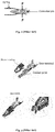
- Fig. 1 schematically illustrates one aspect of this difficulty.
- the upper part of Fig. 1 shows the application of a load to a spring.
- the load applied to the spring linearly raises as a function of time up to a time t o and is then kept constant over time.
- the load of the spring is well within the elasticity region of the elastic material at the time t o , e.g. 50% or 70% of the modulus of elasticity of the spring.
- the lower part of Fig. 1 schematically represents the reaction of the spring to the applied load for three different temperatures, wherein the temperature raises from T 1 to T 3 .
- Fig. 1 illustrates that a spring loses a part of its elasticity or partially relaxes as a function of time and temperature. This means that a spring constant irreversibly reduces during a constant load of a spring over time.
- Fig. 2 schematically shows a male connector pin, a connector pin or simply a pin engaged with a contact terminal, wherein a spring of the contact terminal (which is not shown in Fig. 2 ) provides a contact force F to maintain the connector pin at its predetermined position.
- the lower part of Fig. 1 illustrates that a contact terminal loses a part of its contact force generated by a spring during operation. Even more important, the reduction of the contact force is increases with increasing temperature.
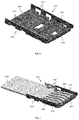
- Fig. 3 represents in the upper part a contact terminal and a respective reinforcing spring element.
- the contact terminal of Fig. 3 is designed to be crimped to a cable.
- the lower part of Fig. 3 shows the reinforcing spring element and the contact terminal in an assembled state.
- Fig. 3 The approach presented in Fig. 3 has several drawbacks. At first, the assembly of the reinforcing spring element and the contact terminal is a complicated process. Further, it is difficult to insert the male connector pin in the contact terminal having two spring elements acting together to enforce each other. In particular, this is effective if the contact spring is completely closed as indicated in Fig. 3 so that a high insertion force is required for engaging a connector pin with the contact terminal. A large insertion force is needed to insert the male connector pin in the contact terminal. More important, the reinforcing spring element of Fig. 3 can reduce the loss of contact force during operation, but cannot remove it. This is illustrated by the following consideration.
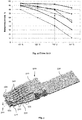
- Fig. 4 depicts the relaxation of different copper alloys having various amounts of nickel (Ni), tin (Sn), silicon (Si) and zinc (Zn) as a function of temperature.
- Fig. 4 is taken from the document " Technical Manual - Connector Strip Materials” of KME Germany GmbH & Co. KG, KMD Connectors Stolberg GmbH .
- the copper alloys are subjected to a load causing an initial stress level (50% Rp0.2) and the load is maintained for 1000 hours at different temperatures.
- the copper alloy having 2-3.2% Ni, 0.1-0.7% Sn, 0.3-0.9 Si and 0.3-1.3% Zn - indicated in Fig. 4 by an arrow - has a remaining stress of a remaining strain of 70% after the test. In other words, the copper alloy has relaxed by 30%, and thus has lost 30% of its elasticity.
- the present invention relates to a contact terminal which is assembled from at least two parts.
- the contact terminal is fabricated from two parts which allows an automated mass production of the contact terminal.
- special contact terminals can be assembled from more than two parts and/or may manually be assembled.
- the contact terminal comprises a base part having at least one contact tongue which is adapted to maintain at least one male connector pin by means of at least one contact tongue surface.
- the at least one contact tongue surface provides a low contact resistance to the male connector pin in order to efficiently transport an electrical and/or a thermal current between the contact tongue and the at least one male connector pin.
- the contact terminal comprises a sleeve which is adapted to be arranged at least partially over the base part.
- the sleeve has at least one spring element which is adapted to contact the at least one contact tongue of the base part on a side which is opposite to the contact tongue surface.
- the contact tongue has a gap which is defined to be equal to or larger than a thickness of the male connector pin prior to assembling the base part and the sleeve.
- the spring element of the sleeve may provide the entire contact force. It is a benefit of an inventive contact terminal to separate the two functions of providing electrical and/or thermal contact and providing a time-independent contact force to a connector pin.
- the contact tongue of the base part can be designed to exclusively provide an electrical and/or a thermal contact to the connector pin, whereas the spring element of the sleeve can be constructed to exclusively provide the contact force to fix the connector pin in the contact terminal.
- the separation of the two functions allows optimizing the contact tongue for an optimal electrical and/or thermal contact to the connector pin and/or to a cable connected to the contact terminal.
- the sleeve, or to be more precisely the spring element can be drafted providing a contact force which is essentially independent of the operation time and the operation temperature (at least up to a temperature of 200 °C) of the contact terminal.
- the contact terminal has a gap which is only little smaller than the thickness of the connector pin. A defined force is needed to open the gap of the contact tongue to the diameter of the connector pin. Consequently, the connector pin can reliably be engaged with the contact terminal by a predetermined insertion force.
- the contact tongue comprises a contact spring.
- the contact spring of the base part and the spring element of the sleeve preload each other at least as long as a male connector is not inserted in the contact spring.
- An inventive contact terminal can be designed according to two application areas.
- the first one in which the gap defined between the contact spring of the base part is equal to the thickness of the connector pin as long as the base part is not assembled in the contact terminal is described in the following.
- the second application area is described below.
- the spring element of the sleeve preloads the contact spring of the assembled base part so that the gap of the contact terminal is smaller than the thickness of the connector pin. Inserting a connector pin into the contact terminal opens the gap of the contact spring to the thickness of the pin.
- the contact spring of the base part is essentially not deflected when a connector pin is engaged in the contact terminal. Since the contact spring is not preloaded during operation of the contact terminal, the contact spring is not subjected to relaxation. Consequently, the contribution of the contact spring to the contact force is essentially not changed even at higher temperatures, as this contribution is essentially zero.
- the gap of the at least one contact spring is smaller than the thickness of the at least one male connector pin after assembling the base part and the sleeve.
- the contact spring and the spring element do not augment each other, but their restoring forces act against each other at least as long as the a connector pin is not inserted in the contact terminal.
- the width of the gap of the contact terminal can be designed by the layout of the sleeve and the spring constant ratios of the contact spring and the spring element. If a spring is loaded within its elasticity regime, it generates a restoring force which is proportional to the load. The restoring force acts in a direction to re-establish the equilibrium condition of the spring, i.e. its position without loading the spring.
- the gap of a contact spring of the base part can have three different widths: A first width is the gap of the contact spring in an unassembled state of the base part. Further, a second width is the gap of the contact spring when the base part and the sleeve are assembled. Moreover, a third width comprises the gap of the contact spring when a male connector pin is inserted into the contact terminal.
- the at least one contact spring is essentially not deflected compared to it prior assembly condition when the at least one male connector pin is engaged with the contact terminal.
- the contact spring Since the contact spring is essentially not deflected from its equilibrium position during operation of the contact terminal, it does essentially not generate a restoring force. Thus, no relaxation occurs within the contact spring. Therefore, the contact terminal does essentially not show a change or reduction of its contact force due to relaxation of the contact spring of the base part.
- the at least on contact spring is deflected towards the at least one spring element when the at least one male connector pin is engaged with the contact terminal.
- the spring element of the sleeve provides a restoring force which is larger than the predetermined contact force to additionally compensate the restoring force generated by the deflected contact spring as the restoring force of the contact spring has a direction which is essentially opposite to the restoring force of the spring element of the sleeve and also the contact force of the contact terminal.
- the at least one spring element comprises spring steel having as modulus of elasticity ⁇ 120 GPa, preferably ⁇ 150 GPa, more preferably ⁇ 170 GPA, and most preferably ⁇ 190 GPa at room temperature.
- the at least one spring element comprises spring steel having a remaining stress ⁇ 85%, preferably ⁇ 90%, more preferred ⁇ 95%, and most preferred ⁇ 98% after a load with 50% of the modulus of elasticity for 1000 hours at a temperature of 200 °C.
- the at least one contact spring comprises an electrical conductivity ⁇ 35 MS/m, preferably ⁇ 40 MS/m, and most preferably ⁇ 45 MS/m, and/or a modulus of elasticity of 50 GPa to 150 GPa.
- the material of the contact spring, and thus of the base part or more generally the material of the contact tongue can be selected to provide an excellent electrical and/or thermal contact to the connector pin of a male contact terminal. A trade-off between conductivity and elasticity of the contact tongue is removed.
- the base part can be fabricated from a material which is both, highly conductive and cost-effective.
- a spring constant of the at least one contact spring and the spring constant of the at least one spring element have a ratio of 1:0.5, preferably 1:1, more preferred 1:1.5, and most preferred 1:2.
- the amount of deflection of the contact spring is essentially inverse proportional to the spring constant ratio of the two springs when no connector pin is inserted in the contact terminal.
- the base part comprises a contact pad or crimping wings.
- the at least one contact spring comprises at least two contact spring parts which are adapted to contact the at least one male connector pin on opposite sides.
- the gap defined between the at least one contact spring expands towards a male connector terminal.
- an inventive contact terminal can have arbitrary means for connecting a cable. It may have means for crimping, soldering, or welding a cable. Further, it is advantageous that the base part can be fabricated from a material which is highly electrically and/or thermally conductive. Thus, an electrical and/or a thermal connection can be established between the contact terminal and a cable having a low contact resistance. Furthermore, a contact spring having at least two symmetrical contact spring parts facilitates the generation of a reliable contact force. A widening of the contact spring towards the end the male contact terminal allows a reduction of the insertion force without compromising the contact force.
- the at least one spring element of the sleeve comprises at least two spring element parts adapted to be arranged at sides of the at least two contact spring parts opposite to the contact spring surfaces.
- the contact spring of the base part and the spring element of the sleeve have a similar symmetry so that the contact terminal exerts a contact force by two opposing spring elements which are deflected instead or one.
- a contact force of the contact terminal which is engaged with the male connector pin is constant within an interval of ⁇ 20%, preferably ⁇ 10%, more preferably ⁇ 5%, and most preferably ⁇ 2% after operating the contact terminal for 1000 hours at a temperature of 200 °C.
- the contact force of the contact terminal can be designed to essentially not show any decrease during the operation of the contact terminal. This is achieved by configuring the base part and the sleeve so that the contact spring of the base part is essentially not stressed during operation, and thus is not subjected to relaxation. Further, it is advantageous that a constant contact force can also be achieved at elevated temperature up to 200 °C. By selecting an appropriate spring steel material, the operation range of the contact terminal can be extended beyond 200 °C.
- the contact force of the contact terminal increases during operation of the contact terminal.
- the contact force increases during an operation of 1000 hours at a temperature of 200 °C by ⁇ 5%, preferably ⁇ 10%, more preferably ⁇ 15%, and most preferably ⁇ 20%.
- the contact spring if a contact spring has a gap which is larger than the thickness of the connector pin, the contact spring is deflected in a direction towards the spring element of the sleeve even if a pin is inserted in the contact spring of the assembled contact terminal.
- the restoring force of the contact spring counteracts the restoring force of the spring element.
- the restoring force of the spring element has to be larger than the contact force of the contact terminal.
- the restoring force of the spring element shows essentially no relaxation as a function of time and temperature.
- the contact spring relaxes during operation and in particular at higher temperatures as it is fabricated of highly electrically and/or thermally conductive material. Therefore, the remaining stress or the restoring force of the contact spring reduces during operation. But, since the restoring forces of both springs act in opposite directions, the contact force exerted by the contact terminal on the connector pin increases during operation.
- an increase of the contact force may be used to at least partially compensating an increase of the transition resistance between the connector pin and the contact spring during operation caused by a pollution and/or corrosion.
- the sleeve comprises a protection against a miss fitting of the at least one male connector pin
- the base part comprises CuSno,15
- the sleeve comprises X10CrNi18-8
- the at least one contact spring comprises twelve contact spring parts arranged in two opposing rows, each one comprising six contact spring parts
- the at least one spring element contacts a row of the contact spring parts
- the at least one male connector pin comprises at least one male blade.
- a method for assembling a contact terminal from at least two parts comprises: (a) providing a base part having at least one contact tongue, the at least one contact tongue having a gap equal to or larger than a thickness of a male connector pin; (b) providing a sleeve adapted to be arranged at least partially over the base part, the sleeve having at least one spring element, the at least one spring element being adapted to contact the at least one contact tongue on a side opposite to a contact tongue surface; and (c) assembling the base part and the sleeve by pushing the base part into the sleeve by which the at least one spring element deflects the at least one contact tongue so that the opening of the at least one contact tongue is smaller than the thickness of the male connector pin.
- the assembly of the base part and the sleeve to the contact terminal can be performed in an automated process by aligning the sleeve and the base part and by pushing the base part into the sleeve.
- the at least one spring element of the sleeve guides the at least one contact tongue of the base part.
- the at least one contact tongue comprises at least one contact spring.
- the diagram 500 of Fig. 5 shows an example of a base part 510.
- the base part 510 comprises a contact spring 520 as an example of a contact tongue and a contact pad 530.
- a cable (not shown in Fig. 5 ) is connected to the contact pad 530.
- the contact pad 530 and the cable are connected by welding, in particular by ultrasonic welding.
- the connection of a base part 510 of a contact terminal is not restricted to welding, rather an inventive contact terminal may be connected to a cable by all usual joining techniques, as for example soldering or crimping.
- the contact pad 530 is adapted to the respective joining technique.
- the exemplary base part 510 of Fig. 5 has crimp wings instead of the contact pad 530 (not shown in Fig. 5 ).
- the contact spring 520 comprises an upper portion 540 and a lower portion 550 arranged symmetrically both in a horizontal and a vertical plane. This configuration of the contact spring 520 facilitates the application of a symmetrical contact force (not shown in Fig. 5 ).
- the exemplary contact spring 520 comprises six contact spring parts 555 on its upper part 540 and six contact spring parts 555 on its lower portion 550.
- the contact spring 520 and thus the contact spring parts 555 comprise leaf springs.
- the contact spring 520 of the base part 510 has a gap 560 which is either designed to essentially correspond to a thickness of a male connector pin (not represented in Fig.
- the gap 560 is essentially 1.2 mm.
- the length, width and thickness of the contact spring elements 555 is 8 mm, 1.2 mm, and 0.59 mm.
- the contact spring parts 555 have a contact spring surface 570 which contacts an inserted connector pin.
- the ends of the upper 580 and lower 585 contact spring parts 555 are bound upwards and downwards, respectively, in order to facilitate the insertion of the connector pin.
- the gap 560 of the base part 510 is defined as the lowest distance between the upper 580 and lower 585 contact spring parts 555.
- Fig. 5 just shows an example of a base part 510.
- the contact spring 510 may comprise two spring elements arranged symmetrically in the horizontal and vertical directions as indicated in Fig. 5 .
- the contact spring 520 comprises a single spring element, for example arranged above an essentially rigid lower plate (not shown in Fig. 5 ).
- a contact spring 520 comprise four contact spring elements, for example arranged on four sides of a square or a rectangle which are adapted to engage with a round, a square or a rectangular male connector pin.
- the base part 510 of Fig. 5 is designed for carrying high currents which are depending on the width of the base part 510 in a range of 70 A to 140 A at a temperature of 70 °C.
- the contact resistance to a connector pin is specified to be ⁇ 0.15 m ⁇ .
- the base part 510 of diagram 500 comprises a copper alloy which comprises Cr, Ti and/or Sn.
- the copper alloy has a lower relaxation loss than pure copper.
- the diagram 600 of Fig. 6 presents an upper part 630 or a lower part 630 of a sleeve 610.
- the sleeve 610 is cut in a horizontal plane.
- the upper or lower part 630 of the sleeve 610 comprises a spring element 630.
- the part 630 of the sleeve 610 comprises four snap-in hooks 640 having the task to fix the base part 510 in an assembled contact terminal.
- a complete sleeve 610 (not shown in Fig. 6 ) comprises two of the parts 630 depicted in Fig. 6 .
- the sleeve 610 preferably comprises spring steel having a high modulus of elasticity.
- the sleeve 610 comprises a CrNi (chromium nickel) steel.
- the sleeve 610 of the example of diagram 600 comprises X10CrNi18-8 which has a modulus of elasticity in the range of 180 GPa to 200 GPa at room temperature. It is possible to fabricate this kind of spring steel having this modulus of elasticity up to a temperature of 300 °C. Consequently, X10CrNi18-8 does not show a significant relaxation up to a temperature of 200 °C. On the other hand, this CrNi steel has only a modest electrical conductivity.
- the part 630 of the sleeve 610 comprises a specifically formed front end 650 which is adapted to guide a connector pin during its insertion process in the contact spring of a contact terminal. Consequently, the rounded front end 650 of the sleeve 610 provides protection against miss fitting of a connector pin.
- Fig. 7 depicts a diagram 700 in which a lower part of the base part 510 of Fig. 5 and a lower part 630 of a sleeve 610 are combined.
- the base part 510 is fixed to the sleeve part 630 by the four snap-in hooks 640.
- Fig. 7 clearly shows the contact spring surface 570 at which a connector pin (not shown in Fig. 7 ) connects the contact spring 510 of a contact terminal.
- Fig. 7 also indicates that the specifically designed front end 650 of the sleeve 610 guides a connector pin during insertion in the contact terminal.
- the diagram 800 of Fig. 8 shows a vertical cut through the diagram 700 along its horizontal symmetry line.
- Fig. 8 represents the layout of the base part 510 on the sleeve 610 in an assembled state.
- the diagram 800 depicts the spatial arrangement of the spring element 620 of the sleeve 610 and the contact spring 520 of the base part 510.
- the contact spring surface 570 at which the contact spring 510 contacts a pin connector essentially is above the area 870 the spring element 620 exerts a force to the contact spring 520.
- the diagram 900 of Fig. 9 represents a contact terminal 910 comprising a base part 510 and a sleeve 610.
- the base part 510 is fixed in the sleeve 610 by four snap-in hooks 640 on both sides of the sleeve 610.
- the diagram 1000 of Fig. 10 shows a vertical cut through a base terminal 510 and a sleeve 610.
- the base terminal 510 and the sleeve 610 are aligned to each other and the base terminal 510 is partly inserted into the sleeve 610. This is indicated by the arrow 1050.
- the base part 510 is pushed into the sleeve 610 to an extent that the contact spring 520 of the base part 510 and the spring element 620 of the sleeve are not yet in contact with each other.
- the opening 560 of the contact spring 510 is still the opening of the contact spring 510 of Fig. 5 which is essentially 1.2 mm in the example of Fig. 10 .
- the opening 1060 of the spring element 620 of the sleeve 610 amounts to 1.82 mm in the example of Fig. 10 .
- the thickness of the contact spring 520 is essentially 0.59 mm. In this position, both the spring element 620 and the contact spring 520 are not deflected. Consequently, no restoring force occurs neither from the spring element 620 nor from the contact spring 520:
- the diagram 1100 of Fig. 11 represents the configuration when the base part 510 is completely pushed into the sleeve 610, i.e. the base part 510 and the sleeve are assembled to the contact terminal 910.
- the spring element 620 of the sleeve 610 guides the contact spring 520 of the base part 510 in its final position.
- the contact spring 520 does not abut against the front end 650 of the sleeve 610 in the assembled condition so that the contact spring 510 can freely move in the vertical direction.
- the diagram 1200 of Fig. 12 represents the contact terminal 910 of Figures 9 and 11 in which a male connector pin 1210 is inserted.
- the connector pin 1210 has essentially a thickness 1220 of 1.2 mm.
- the gap 568 essentially corresponds the thickness 1220 of the connector pin 1210. Since the gap 565 of Fig. 11 has a width of about two third of the pin thickness (0.76 to 1.2 mm) the connector pin 1210 can easily be inserted in the contact terminal 910.
- a reduced insertion force is achieved because the contact spring 520 works against the spring element 620 until the male connector pin 1210 is engaged with the contact terminal 910.
- This means that the design of insertion tools can be simplified compared to conventional preloaded springs such as the one indicated in Fig. 3 .
- an insertion force ⁇ 25 N is specified which is achieved with the contact terminal 910 of Fig. 12 .
- This restoring force of the spring elements 620 of the sleeve 610 provide the contact force of the contact terminal 910.
- the spring elements 620 of the sleeve 610 essentially generate 100% of the contact force of the contact terminal. It is not necessary to increase the sleeve material thickness in order to obtain the discussed contact force.
- the spring element 620 may be designed to have a high stiffness. Moreover, as already discussed above, the spring element 620 can be configured to essentially show no relaxation even at temperatures beyond 200 °C.
- the gap 560 of an unassembled contact spring 520 is larger than the thickness of the connector pin 1210 and thus the gap 568.
- the spring elements 620 in the upper and lower part 630 of the sleeve 610 have to have a larger spring constant, i.e. the spring elements 620 have to be stiffer than in the configuration of Figures 10 to 12 . If this is the case, the restoring forces with which the contact spring 520 and the spring elements 620 preload each other when no connector pin 1210 is inserted in the contact terminal 910 are higher than the ones discussed in the context to Fig. 11 .
- the restoring force of the contact spring 520 (preferably fabricated from a copper alloy) is subjected to relaxation whereas the restoring force of the spring elements 620 (preferably fabricated from spring steel) are essentially not changed during operation.
- the resulting contact force is the sum of the restoring forces of the spring element 620 and the contact spring 520.
- a contact force exerted to a connector pin 1210 slowly increases during operation in a contact terminal having such a contact spring.
- the diagram 1300 of Fig. 13 presents an enlarged a cut-out of Fig. 12 . It shows that in the contact terminal 910 the contact spring surface 570 is not precisely above the above the area 870 at which the spring element 620 exerts a force to the contact spring 520. The following considerations refer to the contact area 870 or the shoulder point 870.
- Fig. 14 shows a diagram 1400 in which the deflections d and the restoring forces of the spring element 620 and the contact spring 520 from Figures 10 to 12 are illustrated.
- the following consideration apply to one of the two spring elements 620 of the sleeve 610 (the upper one or the lower one) and to one of the symmetrical portions of the spring element portions 540 or 550 of the contact spring 520.
- the gap 560 is 1.2 mm
- no restoring forces occur i.e.
- the two springs 520 and 620 are preloaded by a restoring force of 12.9 N resulting in a gap 565 of 0.76 mm.
- the resulting spring constants 1430 and 1440 are also in good agreement.
- the diagram 1500 of Fig. 15 presents the strain energy or the deformation energy stored in the contact spring 520 of the base part 510 and the spring element 620 of the sleeve 610 as well as the overall strain energy stored in both springs 520 and 620 in level 1 ( Fig. 11 ) and level 2 ( Fig. 12 ) as a function of time.
- the contact terminal 910 is assembled from the base part 510 and the sleeve 610, and the contact spring 520 and the spring element 620 push against each other.
- the strain energy 1510 stored in the spring contact 520 is thus larger than the strain energy 1520 of the spring element 620, since the strain energy varies with the square of the deflection.
- the overall spring energy 1530 in level 1 is the sum of the deformation energies stored in both springs 520 and 620.
- the strain energies 1510, 520 of the base part 510, the sleeve 610 as well as of the overall strain energy 1530 are referred to the overall strain energy 1530 when a male connector pin 1210 is engaged with the contact terminal 910 which is defined as 100% of the strain energy 1530.
- Fig. 15 depicts that the insertion process of the male connector pin 1210 in the contact terminal 910 begins at about the time indicated by the arrow 1550 in the exemplary diagram 1500.
- the data of Fig. 15 are obtained from FEA results.
- the contact spring 520 releases its strain energy 1510 which is taken over by the spring element 620 of the sleeve. Due the increasing deflection of the spring element 620, the strain energy 1520 stored in the spring element 620 steeply raises during the insertion process.
- the strain energy 1530 of the spring system 520 and 620 is essentially stored in the spring element 620. This means that in the example of Fig. 15 only a small share of 1.7% of the strain energy is stored in the contact spring 510 at level 2, whereas at level 1 the contact spring store the larger portion of the total strain energy 1530.
- the diagram 1600 of Fig. 16 is a cross check of the stored strain energy in level 1 and level 2 calculated from the data of Fig. 14 .
- the strain energy data of Figures 14 and 16 correspond well with each other.
- the flow chart 1700 of Fig. 17 illustrates a method for assembling a contact terminal 910.
- the method begins with step 1710.
- a base part 510 is provided.
- the base part 510 has at least one contact tongue which has a gap 560 which is equal to or larger than a thickness of a male connector pin 1210 which is adapted to be inserted in the contact terminal 910.
- the thickness of the male connector pin 1210 corresponds to the gap 568.
- a sleeve 610 is provided. The sleeve 610 is adapted to be at least partially arranged over the base part 510.
- the sleeve 610 has at least one spring element 620 which can contact the at least one contact tongue on a side which is opposite to the contact tongue surface. Moreover, at step 1740, the base part 510 and the sleeve 610 are aligned with respect to each other. Then the base part 510 is pushed in the sleeve 610 by which the at least one spring element 620 deflects the at least one contact tongue so that the gap 565 of the at least one contact tongue is smaller than a thickness of the male connector pin 1210.
Landscapes
- Coupling Device And Connection With Printed Circuit (AREA)
Abstract
The present invention refers to a contact terminal (910) which is assembled from at least two parts. The contact terminal (910) comprises a base part (510) having at least one contact tongue which is adapted to maintain at least one male connector pin (1210) by means of at least one contact tongue surface. Furthermore, the contact terminal (910) comprises a sleeve (610) which is adapted to be arranged at least partially over the base part (510). The sleeve (610) has at least one spring element (620) which is adapted to contact the at least one contact tongue of the base part (510) on a side which is opposite to the contact tongue surface. Moreover, the contact tongue has an opening (560) which is equal to or larger than a thickness (1220) of the male connector pin (1210) prior to assembling the base part (510) and the sleeve 610).
Description
- The present invention refers to a contact terminal, and in particular to a contact terminal which is assembled from at least two parts.
- Connector systems are used to connect various cables, such as for example telecommunication cables, networking cables, other signaling cables or in general any electrical, optical and/or thermal wiring. Electrical connector systems are used for joining electrical circuits, wherein typically a male-ended plug or a male contact terminal is adapted to connect to a female-ended jack or a female contact terminal. In many applications a safe and in particular a reliable coupling of connectors or contact terminals is of high importance. For example, in the automotive industry more and more electronic components are added to cars and/or trucks. Due to limited space available in a car, in particular in the engine compartment, components are steadily more tightly packed in the engine compartment. As a consequence of this the temperature continuously increases in the engine compartment with each new engine generation. Higher temperatures result in higher stress of active electrical components, but also leads to higher thermal loads of passive components, as for example contact terminals. This may lead to reliability problems of contact terminals.
-
Fig. 1 schematically illustrates one aspect of this difficulty. The upper part ofFig. 1 shows the application of a load to a spring. The load applied to the spring linearly raises as a function of time up to a time to and is then kept constant over time. The load of the spring is well within the elasticity region of the elastic material at the time to, e.g. 50% or 70% of the modulus of elasticity of the spring. The lower part ofFig. 1 schematically represents the reaction of the spring to the applied load for three different temperatures, wherein the temperature raises from T1 to T3.Fig. 1 illustrates that a spring loses a part of its elasticity or partially relaxes as a function of time and temperature. This means that a spring constant irreversibly reduces during a constant load of a spring over time. -
Fig. 2 schematically shows a male connector pin, a connector pin or simply a pin engaged with a contact terminal, wherein a spring of the contact terminal (which is not shown inFig. 2 ) provides a contact force F to maintain the connector pin at its predetermined position. The lower part ofFig. 1 illustrates that a contact terminal loses a part of its contact force generated by a spring during operation. Even more important, the reduction of the contact force is increases with increasing temperature. - Up to now this problem is tackled by a reinforcing spring element which is combined with a contact terminal.
Fig. 3 represents in the upper part a contact terminal and a respective reinforcing spring element. The contact terminal ofFig. 3 is designed to be crimped to a cable. The lower part ofFig. 3 shows the reinforcing spring element and the contact terminal in an assembled state. - The approach presented in
Fig. 3 has several drawbacks. At first, the assembly of the reinforcing spring element and the contact terminal is a complicated process. Further, it is difficult to insert the male connector pin in the contact terminal having two spring elements acting together to enforce each other. In particular, this is effective if the contact spring is completely closed as indicated inFig. 3 so that a high insertion force is required for engaging a connector pin with the contact terminal. A large insertion force is needed to insert the male connector pin in the contact terminal. More important, the reinforcing spring element ofFig. 3 can reduce the loss of contact force during operation, but cannot remove it. This is illustrated by the following consideration. -
Fig. 4 depicts the relaxation of different copper alloys having various amounts of nickel (Ni), tin (Sn), silicon (Si) and zinc (Zn) as a function of temperature.Fig. 4 is taken from the document "Technical Manual - Connector Strip Materials" of KME Germany GmbH & Co. KG, KMD Connectors Stolberg GmbH. The copper alloys are subjected to a load causing an initial stress level (50% Rp0.2) and the load is maintained for 1000 hours at different temperatures. For example, the copper alloy having 2-3.2% Ni, 0.1-0.7% Sn, 0.3-0.9 Si and 0.3-1.3% Zn - indicated inFig. 4 by an arrow - has a remaining stress of a remaining strain of 70% after the test. In other words, the copper alloy has relaxed by 30%, and thus has lost 30% of its elasticity. - It is now assumed that the contact terminal essentially consists of this copper alloy. It is further assumed that in the initial state the contact terminal provides 70% and the reinforcing spring element provides 30% of the contact force exerted by the contact terminal of
Fig. 3 . Moreover, it is supposed that the reinforcing spring element does not have any relaxation up to a temperature of 150 °C). Under these conditions the contact force of the contact terminal ofFig. 3 is reduced by 0.7 x 0.3 = 21% after an operation period of 1000 hours when the load of the spring of the contact terminal ofFig. 2 is similar to the stress level of the copper alloy during the test ofFig. 4 . - As can clearly be recognized from
Fig. 4 , the discussed difficulty get worse by the tendency to specify operation temperatures of contact terminals which are higher than 150 °C. - It is an object of the present invention to provide a contact terminal that has a contact force which is essentially independent from the operation time of the contact terminal. It is in particular an object of the present invention to provide a contact terminal which enables an operation at temperatures beyond 150 °C without a significant change of its contact force. It is a further object to provide a contact terminal which reverses the relaxation trend and has a contact force which increases during its operation.
- These and other objects, which become apparent by reading the following description, are achieved by a connector terminal according to the subject matter of
claim 1. - The present invention relates to a contact terminal which is assembled from at least two parts. Preferably, the contact terminal is fabricated from two parts which allows an automated mass production of the contact terminal. But, special contact terminals can be assembled from more than two parts and/or may manually be assembled.
- The contact terminal comprises a base part having at least one contact tongue which is adapted to maintain at least one male connector pin by means of at least one contact tongue surface. The at least one contact tongue surface provides a low contact resistance to the male connector pin in order to efficiently transport an electrical and/or a thermal current between the contact tongue and the at least one male connector pin.
- Furthermore, the contact terminal comprises a sleeve which is adapted to be arranged at least partially over the base part. The sleeve has at least one spring element which is adapted to contact the at least one contact tongue of the base part on a side which is opposite to the contact tongue surface.
- Moreover, the contact tongue has a gap which is defined to be equal to or larger than a thickness of the male connector pin prior to assembling the base part and the sleeve.
- In an inventive contact tongue the spring element of the sleeve may provide the entire contact force. It is a benefit of an inventive contact terminal to separate the two functions of providing electrical and/or thermal contact and providing a time-independent contact force to a connector pin. The contact tongue of the base part can be designed to exclusively provide an electrical and/or a thermal contact to the connector pin, whereas the spring element of the sleeve can be constructed to exclusively provide the contact force to fix the connector pin in the contact terminal. The separation of the two functions allows optimizing the contact tongue for an optimal electrical and/or thermal contact to the connector pin and/or to a cable connected to the contact terminal. The sleeve, or to be more precisely the spring element can be drafted providing a contact force which is essentially independent of the operation time and the operation temperature (at least up to a temperature of 200 °C) of the contact terminal.
- Moreover, in contrast to
Fig. 3 , the contact terminal has a gap which is only little smaller than the thickness of the connector pin. A defined force is needed to open the gap of the contact tongue to the diameter of the connector pin. Consequently, the connector pin can reliably be engaged with the contact terminal by a predetermined insertion force. - The term "essentially" as used here and at other passages of this application denotes a statement of a measured quantities within errors margin according to the art.
- In another aspect, the contact tongue comprises a contact spring.
- In an assembled state of the contact terminal the contact spring of the base part and the spring element of the sleeve preload each other at least as long as a male connector is not inserted in the contact spring.
- An inventive contact terminal can be designed according to two application areas. The first one in which the gap defined between the contact spring of the base part is equal to the thickness of the connector pin as long as the base part is not assembled in the contact terminal is described in the following. The second application area is described below.
- If the gap of the unassembled contact spring essentially corresponds to the thickness of the male connector pin, the spring element of the sleeve preloads the contact spring of the assembled base part so that the gap of the contact terminal is smaller than the thickness of the connector pin. Inserting a connector pin into the contact terminal opens the gap of the contact spring to the thickness of the pin. However, for the contact spring, this is equivalent to the situation prior to the assembly of the base part and the sleeve to a contact terminal. Therefore, the contact spring of the base part is essentially not deflected when a connector pin is engaged in the contact terminal. Since the contact spring is not preloaded during operation of the contact terminal, the contact spring is not subjected to relaxation. Consequently, the contribution of the contact spring to the contact force is essentially not changed even at higher temperatures, as this contribution is essentially zero.
- In a further aspect, the gap of the at least one contact spring is smaller than the thickness of the at least one male connector pin after assembling the base part and the sleeve.
- This condition secures that the contact terminal can reliably maintain the connector pin at its predetermined position. It also enables that a defined contact force can be applied to the connector pin. Different to the prior art, the contact spring and the spring element do not augment each other, but their restoring forces act against each other at least as long as the a connector pin is not inserted in the contact terminal. The width of the gap of the contact terminal can be designed by the layout of the sleeve and the spring constant ratios of the contact spring and the spring element. If a spring is loaded within its elasticity regime, it generates a restoring force which is proportional to the load. The restoring force acts in a direction to re-establish the equilibrium condition of the spring, i.e. its position without loading the spring.
- The gap of a contact spring of the base part can have three different widths: A first width is the gap of the contact spring in an unassembled state of the base part. Further, a second width is the gap of the contact spring when the base part and the sleeve are assembled. Moreover, a third width comprises the gap of the contact spring when a male connector pin is inserted into the contact terminal.
- According to another aspect, the at least one contact spring is essentially not deflected compared to it prior assembly condition when the at least one male connector pin is engaged with the contact terminal.
- Since the contact spring is essentially not deflected from its equilibrium position during operation of the contact terminal, it does essentially not generate a restoring force. Thus, no relaxation occurs within the contact spring. Therefore, the contact terminal does essentially not show a change or reduction of its contact force due to relaxation of the contact spring of the base part.
- In a preferred aspect, the at least on contact spring is deflected towards the at least one spring element when the at least one male connector pin is engaged with the contact terminal.
- This configuration describes the above mentioned second application area. If the gap of the contact spring of the unassembled base part is larger than the thickness of the connector pin, the spring element of the sleeve preloads the contact spring in the contact terminal also when a male connector pin is engaged with the contact spring. However, also in this situation, the deflection of the contact spring causes a restoring force which is opposite to the force F indicated in
Fig. 2 . In order to generate a predetermined contact force, the spring element of the sleeve provides a restoring force which is larger than the predetermined contact force to additionally compensate the restoring force generated by the deflected contact spring as the restoring force of the contact spring has a direction which is essentially opposite to the restoring force of the spring element of the sleeve and also the contact force of the contact terminal. - In a further preferred aspect, the at least one spring element comprises spring steel having as modulus of elasticity ≥ 120 GPa, preferably ≥ 150 GPa, more preferably ≥ 170 GPA, and most preferably ≥ 190 GPa at room temperature.
- In a beneficial aspect, the at least one spring element comprises spring steel having a remaining stress ≥ 85%, preferably ≥ 90%, more preferred ≥ 95%, and most preferred ≥ 98% after a load with 50% of the modulus of elasticity for 1000 hours at a temperature of 200 °C.
- The data indicated above apply for a test temperature of 200 °C. A relaxation of the spring steel of the sleeve, and thus of the spring element is essentially not noticeable for operation temperature ranges of a contact terminal (-40 °C to 150 °C) which are usual nowadays.
- In an advantageous aspect, the at least one contact spring comprises an electrical conductivity ≥ 35 MS/m, preferably ≥ 40 MS/m, and most preferably ≥ 45 MS/m, and/or a modulus of elasticity of 50 GPa to 150 GPa.
- As already mentioned above, the material of the contact spring, and thus of the base part or more generally the material of the contact tongue can be selected to provide an excellent electrical and/or thermal contact to the connector pin of a male contact terminal. A trade-off between conductivity and elasticity of the contact tongue is removed. Thus, the base part can be fabricated from a material which is both, highly conductive and cost-effective.
- According to still a further aspect, a spring constant of the at least one contact spring and the spring constant of the at least one spring element have a ratio of 1:0.5, preferably 1:1, more preferred 1:1.5, and most preferred 1:2.
- If it is assumed that the contact point of the contact spring to the connector pin and the contact point of the contact spring to the spring element have a distance which essentially corresponds to the thickness of the contact spring, the amount of deflection of the contact spring is essentially inverse proportional to the spring constant ratio of the two springs when no connector pin is inserted in the contact terminal.
- In yet a further beneficial aspect, the base part comprises a contact pad or crimping wings. According to a preferred aspect, the at least one contact spring comprises at least two contact spring parts which are adapted to contact the at least one male connector pin on opposite sides. In another advantageous aspect, the gap defined between the at least one contact spring expands towards a male connector terminal.
- It is beneficial that an inventive contact terminal can have arbitrary means for connecting a cable. It may have means for crimping, soldering, or welding a cable. Further, it is advantageous that the base part can be fabricated from a material which is highly electrically and/or thermally conductive. Thus, an electrical and/or a thermal connection can be established between the contact terminal and a cable having a low contact resistance. Furthermore, a contact spring having at least two symmetrical contact spring parts facilitates the generation of a reliable contact force. A widening of the contact spring towards the end the male contact terminal allows a reduction of the insertion force without compromising the contact force.
- According to still another aspect, the at least one spring element of the sleeve comprises at least two spring element parts adapted to be arranged at sides of the at least two contact spring parts opposite to the contact spring surfaces.
- It is beneficial that the contact spring of the base part and the spring element of the sleeve have a similar symmetry so that the contact terminal exerts a contact force by two opposing spring elements which are deflected instead or one.
- In another preferred aspect, a contact force of the contact terminal which is engaged with the male connector pin is constant within an interval of ±20%, preferably ±10%, more preferably ± 5%, and most preferably ±2% after operating the contact terminal for 1000 hours at a temperature of 200 °C.
- It is one of the major benefits that the contact force of the contact terminal can be designed to essentially not show any decrease during the operation of the contact terminal. This is achieved by configuring the base part and the sleeve so that the contact spring of the base part is essentially not stressed during operation, and thus is not subjected to relaxation. Further, it is advantageous that a constant contact force can also be achieved at elevated temperature up to 200 °C. By selecting an appropriate spring steel material, the operation range of the contact terminal can be extended beyond 200 °C.
- In still a further beneficial aspect, the contact force of the contact terminal increases during operation of the contact terminal. According to another advantageous aspect, the contact force increases during an operation of 1000 hours at a temperature of 200 °C by ≥ 5%, preferably ≥ 10%, more preferably ≥ 15%, and most preferably ≥ 20%.
- The term "during operation" means here as well as at other positions of this application that at least one connector pin is engaged with the contact terminal.
- As already outlined above, if a contact spring has a gap which is larger than the thickness of the connector pin, the contact spring is deflected in a direction towards the spring element of the sleeve even if a pin is inserted in the contact spring of the assembled contact terminal. This means that the restoring force of the contact spring counteracts the restoring force of the spring element. Thus, in order to generate a predetermined contact force, the restoring force of the spring element has to be larger than the contact force of the contact terminal. As described above, the restoring force of the spring element shows essentially no relaxation as a function of time and temperature. On the other hand, as indicated in
Fig. 4 , the contact spring relaxes during operation and in particular at higher temperatures as it is fabricated of highly electrically and/or thermally conductive material. Therefore, the remaining stress or the restoring force of the contact spring reduces during operation. But, since the restoring forces of both springs act in opposite directions, the contact force exerted by the contact terminal on the connector pin increases during operation. - For example, an increase of the contact force may be used to at least partially compensating an increase of the transition resistance between the connector pin and the contact spring during operation caused by a pollution and/or corrosion.
- According to still a further aspect, the sleeve comprises a protection against a miss fitting of the at least one male connector pin, the base part comprises CuSno,15, the sleeve comprises X10CrNi18-8, the at least one contact spring comprises twelve contact spring parts arranged in two opposing rows, each one comprising six contact spring parts, the at least one spring element contacts a row of the contact spring parts, and/or the at least one male connector pin comprises at least one male blade.
- In another preferred aspect, a method for assembling a contact terminal from at least two parts comprises: (a) providing a base part having at least one contact tongue, the at least one contact tongue having a gap equal to or larger than a thickness of a male connector pin; (b) providing a sleeve adapted to be arranged at least partially over the base part, the sleeve having at least one spring element, the at least one spring element being adapted to contact the at least one contact tongue on a side opposite to a contact tongue surface; and (c) assembling the base part and the sleeve by pushing the base part into the sleeve by which the at least one spring element deflects the at least one contact tongue so that the opening of the at least one contact tongue is smaller than the thickness of the male connector pin.
- The assembly of the base part and the sleeve to the contact terminal can be performed in an automated process by aligning the sleeve and the base part and by pushing the base part into the sleeve. During the assembly process, the at least one spring element of the sleeve guides the at least one contact tongue of the base part.
- According to a further aspect, the at least one contact tongue comprises at least one contact spring.
- In order to better understand the present invention and to appreciate its practical applications, the following figures are provided and referenced hereafter. It should be noted that the figures are given as examples only and in no way limit the scope of the invention.
- Fig. 1
- schematically shows in the upper part a linear increase of a load applied to a spring followed by a time-independent load, the lower part depicts the elasticity of the spring as a function of time and temperature;
- Fig. 2
- schematically represents a contact spring of a contact terminal engaged with a male connector pin and indicates a contact force F exerted by the contact spring to the male connector pin;
- Fig. 3
- shows in the upper part a contact terminal comprising a base part and a contact spring and a sleeve spring or a reinforcing spring and in the lower part the sleeve spring assembled with the contact terminal;
- Fig. 4
- represents relaxation curves or curves of remaining stress of various copper alloys as a function of temperature for a predetermined load;
- Fig. 5
- depicts a base part of a contact terminal with a contact spring;
- Fig. 6
- shows a lower portion or an upper portion of a sleeve of a contact terminal with a spring element;
- Fig. 7
- represents the lower part of a contact terminal assembled from the base part of
Fig. 5 and the sleeve ofFig. 6 ; - Fig. 8
- shows a cross section of
Fig. 7 ; - Fig. 9
- depicts a contact terminal;
- Fig. 10
- represents a cross section of a base part and a sleeve aligned to each other, wherein the base part is partially inserted into the sleeve;
- Fig. 11
- indicates
Fig. 10 after the base part is completely inserted in the sleeve; - Fig. 12
- presents the assembled contact terminal of
Fig. 11 , wherein a male connector pin is engaged with the contact terminal; - Fig. 13
- shows an enlarged cut-out of a
Fig. 12 indicating a contact area of the contact spring and the spring element and a contact spring surface contacting the connector pin; - Fig. 14
- depicts the restoring forces of the contact spring and the spring element in the configurations of
Figures 10 to 12 ; - Fig. 15
- represents the strain energy stored by the contact spring of the base part and the spring element of the sleeve in the configurations of
Figures 11 and 12 ; - Fig. 16
- shows a cross check of
Fig. 15 on the basis ofFig. 14 ; and - Fig. 17
- summarizes the method steps for assembling a contact terminal from a base part and a sleeve.
- In the following, the present invention will now be described in more detail hereinafter with reference to the accompanying figures, in which exemplary embodiments of the invention are illustrated. However, the present invention may be embodied in different forms and should not be construed as limited to the embodiments set forth herein. Rather, these embodiments are provided so that this disclosure will be thorough and will convey the scope of the invention to persons skilled in the art.
- The diagram 500 of
Fig. 5 shows an example of abase part 510. In the example ofFig. 5 thebase part 510 comprises acontact spring 520 as an example of a contact tongue and acontact pad 530. A cable (not shown inFig. 5 ) is connected to thecontact pad 530. In the example represented inFig. 5 , thecontact pad 530 and the cable are connected by welding, in particular by ultrasonic welding. However, the connection of abase part 510 of a contact terminal is not restricted to welding, rather an inventive contact terminal may be connected to a cable by all usual joining techniques, as for example soldering or crimping. Thecontact pad 530 is adapted to the respective joining technique. - In a preferred alternative embodiment, the
exemplary base part 510 ofFig. 5 has crimp wings instead of the contact pad 530 (not shown inFig. 5 ). - In the example of
Fig. 5 , thecontact spring 520 comprises anupper portion 540 and alower portion 550 arranged symmetrically both in a horizontal and a vertical plane. This configuration of thecontact spring 520 facilitates the application of a symmetrical contact force (not shown inFig. 5 ). Theexemplary contact spring 520 comprises sixcontact spring parts 555 on itsupper part 540 and sixcontact spring parts 555 on itslower portion 550. In the example ofFig. 5 , thecontact spring 520 and thus thecontact spring parts 555 comprise leaf springs. Thecontact spring 520 of thebase part 510 has agap 560 which is either designed to essentially correspond to a thickness of a male connector pin (not represented inFig. 5 ) or which is larger than the thickness of the male connector pin. In the example ofFig. 5 , thegap 560 is essentially 1.2 mm. The length, width and thickness of thecontact spring elements 555 is 8 mm, 1.2 mm, and 0.59 mm. Thecontact spring parts 555 have acontact spring surface 570 which contacts an inserted connector pin. The ends of the upper 580 and lower 585contact spring parts 555 are bound upwards and downwards, respectively, in order to facilitate the insertion of the connector pin. Thegap 560 of thebase part 510 is defined as the lowest distance between the upper 580 and lower 585contact spring parts 555. -
Fig. 5 just shows an example of abase part 510. Thecontact spring 510 may comprise two spring elements arranged symmetrically in the horizontal and vertical directions as indicated inFig. 5 . It is also possible that thecontact spring 520 comprises a single spring element, for example arranged above an essentially rigid lower plate (not shown inFig. 5 ). Further, it is also conceivable that acontact spring 520 comprise four contact spring elements, for example arranged on four sides of a square or a rectangle which are adapted to engage with a round, a square or a rectangular male connector pin. - The
base part 510 ofFig. 5 is designed for carrying high currents which are depending on the width of thebase part 510 in a range of 70 A to 140 A at a temperature of 70 °C. The contact resistance to a connector pin is specified to be < 0.15 mΩ. Thebase part 510 of diagram 500 comprises a copper alloy which comprises Cr, Ti and/or Sn. The copper alloy has a lower relaxation loss than pure copper. - The diagram 600 of
Fig. 6 presents anupper part 630 or alower part 630 of asleeve 610. Thesleeve 610 is cut in a horizontal plane. The upper orlower part 630 of thesleeve 610 comprises aspring element 630. Furthermore, thepart 630 of thesleeve 610 comprises four snap-inhooks 640 having the task to fix thebase part 510 in an assembled contact terminal. A complete sleeve 610 (not shown inFig. 6 ) comprises two of theparts 630 depicted inFig. 6 . - In the example of
Fig. 6 , thesleeve 610 preferably comprises spring steel having a high modulus of elasticity. InFig. 6 thesleeve 610 comprises a CrNi (chromium nickel) steel. To be more precise, thesleeve 610 of the example of diagram 600 comprises X10CrNi18-8 which has a modulus of elasticity in the range of 180 GPa to 200 GPa at room temperature. It is possible to fabricate this kind of spring steel having this modulus of elasticity up to a temperature of 300 °C. Consequently, X10CrNi18-8 does not show a significant relaxation up to a temperature of 200 °C. On the other hand, this CrNi steel has only a modest electrical conductivity. - The
part 630 of thesleeve 610 comprises a specifically formedfront end 650 which is adapted to guide a connector pin during its insertion process in the contact spring of a contact terminal. Consequently, the roundedfront end 650 of thesleeve 610 provides protection against miss fitting of a connector pin. -
Fig. 7 depicts a diagram 700 in which a lower part of thebase part 510 ofFig. 5 and alower part 630 of asleeve 610 are combined. Thebase part 510 is fixed to thesleeve part 630 by the four snap-inhooks 640.Fig. 7 clearly shows thecontact spring surface 570 at which a connector pin (not shown inFig. 7 ) connects thecontact spring 510 of a contact terminal. Further,Fig. 7 also indicates that the specifically designedfront end 650 of thesleeve 610 guides a connector pin during insertion in the contact terminal. - The diagram 800 of
Fig. 8 shows a vertical cut through the diagram 700 along its horizontal symmetry line.Fig. 8 represents the layout of thebase part 510 on thesleeve 610 in an assembled state. In particular, the diagram 800 depicts the spatial arrangement of thespring element 620 of thesleeve 610 and thecontact spring 520 of thebase part 510. As can be recognized fromFig. 8 , thecontact spring surface 570 at which thecontact spring 510 contacts a pin connector essentially is above thearea 870 thespring element 620 exerts a force to thecontact spring 520. - The diagram 900 of
Fig. 9 represents acontact terminal 910 comprising abase part 510 and asleeve 610. Thebase part 510 is fixed in thesleeve 610 by four snap-inhooks 640 on both sides of thesleeve 610. - In the following the assembly of a
base part 510 and asleeve 610 to a contact terminal is explained in more detail. The diagram 1000 ofFig. 10 shows a vertical cut through abase terminal 510 and asleeve 610. Thebase terminal 510 and thesleeve 610 are aligned to each other and thebase terminal 510 is partly inserted into thesleeve 610. This is indicated by thearrow 1050. Thebase part 510 is pushed into thesleeve 610 to an extent that thecontact spring 520 of thebase part 510 and thespring element 620 of the sleeve are not yet in contact with each other. In this position theopening 560 of thecontact spring 510 is still the opening of thecontact spring 510 ofFig. 5 which is essentially 1.2 mm in the example ofFig. 10 . Theopening 1060 of thespring element 620 of thesleeve 610 amounts to 1.82 mm in the example ofFig. 10 . As already indicated above, the thickness of thecontact spring 520 is essentially 0.59 mm. In this position, both thespring element 620 and thecontact spring 520 are not deflected. Consequently, no restoring force occurs neither from thespring element 620 nor from the contact spring 520: FCS = FSE = 0 N. - The diagram 1100 of
Fig. 11 represents the configuration when thebase part 510 is completely pushed into thesleeve 610, i.e. thebase part 510 and the sleeve are assembled to thecontact terminal 910. During the final step of pushing thebase part 510 into thesleeve 610, i.e. between the configurations ofFig. 10 and Fig. 11 , thespring element 620 of thesleeve 610 guides thecontact spring 520 of thebase part 510 in its final position. As can be seen fromFig. 11 , thecontact spring 520 does not abut against thefront end 650 of thesleeve 610 in the assembled condition so that thecontact spring 510 can freely move in the vertical direction. - In the assembled state of
Fig. 11 , theopening 1065 of thespring element 620 is 2.05 mm which means that thespring element 620 is deflected by thecontact spring 520 by 0.23mm = 2.05 mm - 1.82 mm. Thegap 565 of thecontact spring 520 is 0.76 mm. Consequently, thecontact spring surface 570 of thecontact spring 520 is deflected by 0.44 mm = 1.2 mm - 0.76 mm. A finite element analysis (FEA) reveals that the restoring force of the upper and lowercontact spring portions spring element 620 in theupper part 630 and thelower part 630 of thesleeve 610 are 12.9 N, i.e. FCS = FSE = 2 x 12.9 N = 25.8 N. This means that thecontact spring 520 and thespring element 620 preload each other with this force. - The diagram 1200 of
Fig. 12 represents thecontact terminal 910 ofFigures 9 and11 in which amale connector pin 1210 is inserted. Theconnector pin 1210 has essentially athickness 1220 of 1.2 mm. Thus, thegap 568 essentially corresponds thethickness 1220 of theconnector pin 1210. Since thegap 565 ofFig. 11 has a width of about two third of the pin thickness (0.76 to 1.2 mm) theconnector pin 1210 can easily be inserted in thecontact terminal 910. A reduced insertion force is achieved because thecontact spring 520 works against thespring element 620 until themale connector pin 1210 is engaged with thecontact terminal 910. This means that the design of insertion tools can be simplified compared to conventional preloaded springs such as the one indicated inFig. 3 . For the example represented byFig. 12 an insertion force ≤ 25 N is specified which is achieved with thecontact terminal 910 ofFig. 12 . - In the operation condition of the
contact terminal 910, i.e. with an engagedmale connector pin 1210, thegap 568 of thecontact spring 520 corresponds to thegap 560 of thecontact spring 520 of thebase part 510 prior to assembling thebase part 510 with thesleeve 610 to thecontact terminal 910. Consequently, thecontact spring 520 is essentially not deflected and it does not generate a restoring force, i.e. Fcs = 0 N. Since thecontact spring 520 of thebase part 510 is not deflected during operation, thecontact spring 520 is not subjected to any relaxation. Thus, thecontact terminal 910 provides a contact force which does not change during the operation of thecontact terminal 910. - On the other hand, the
opening 1265 of thespring element 620 is increased to 2.38 mm = 1.82 mm + 0.56 mm. The FEA mentioned above shows that springelements 620 in thelower part 630 and theupper part 630 of thesleeve 610 each generates a restoring force of 32.5 N, i.e. FSE = 2 x 32.5 N = 65 N. This restoring force of thespring elements 620 of thesleeve 610 provide the contact force of thecontact terminal 910. Thus, in the configuration described inFig. 12 thespring elements 620 of thesleeve 610 essentially generate 100% of the contact force of the contact terminal. It is not necessary to increase the sleeve material thickness in order to obtain the discussed contact force. As discussed above a material having a large modulus of elasticity may be selected. Furthermore, thespring element 620 may be designed to have a high stiffness. Moreover, as already discussed above, thespring element 620 can be configured to essentially show no relaxation even at temperatures beyond 200 °C. - In a further preferred embodiment of the present application (which is not shown in
Figures 10 to 12 ), thegap 560 of anunassembled contact spring 520 is larger than the thickness of theconnector pin 1210 and thus thegap 568. In order to generate a contact force which is similar to the one discussed above, thespring elements 620 in the upper andlower part 630 of thesleeve 610 have to have a larger spring constant, i.e. thespring elements 620 have to be stiffer than in the configuration ofFigures 10 to 12 . If this is the case, the restoring forces with which thecontact spring 520 and thespring elements 620 preload each other when noconnector pin 1210 is inserted in thecontact terminal 910 are higher than the ones discussed in the context toFig. 11 . Then, during the operation, i.e. aconnector pin 1210 is engaged with the contact terminal 910 (Fig. 12 ) the stiffer spring constant of thespring elements 620 exerted a restoring force which is larger than the one indicated inFig. 12 . However, this does not lead to a larger contact force than the one discussed in the context ofFig. 12 . Even during operation thecontact spring 520 is deflected in this configuration to act against the restoring force of thespring elements 620 of thesleeve 610 so that a portion of the restoring force of thespring elements 620 is shielded from theconnector pin 1210. As discussed above, the restoring force of the contact spring 520 (preferably fabricated from a copper alloy) is subjected to relaxation whereas the restoring force of the spring elements 620 (preferably fabricated from spring steel) are essentially not changed during operation. The resulting contact force is the sum of the restoring forces of thespring element 620 and thecontact spring 520. As a consequence, a contact force exerted to aconnector pin 1210 slowly increases during operation in a contact terminal having such a contact spring. - The diagram 1300 of
Fig. 13 presents an enlarged a cut-out ofFig. 12 . It shows that in thecontact terminal 910 thecontact spring surface 570 is not precisely above the above thearea 870 at which thespring element 620 exerts a force to thecontact spring 520. The following considerations refer to thecontact area 870 or theshoulder point 870. -
Fig. 14 shows a diagram 1400 in which the deflections d and the restoring forces of thespring element 620 and thecontact spring 520 fromFigures 10 to 12 are illustrated. The following consideration apply to one of the twospring elements 620 of the sleeve 610 (the upper one or the lower one) and to one of the symmetrical portions of thespring element portions contact spring 520. As discussed in the context ofFig. 10 (level 0) thegap 560 is 1.2 mm, the deflections d of bothsprings - In the
contact terminal 910 ofFig. 11 (level 1), the twosprings gap 565 of 0.76 mm. Thespring element 620 is deflected as indicated inFig. 11 by d = (0.23 mm)/2 = 0.115 mm. This results in aspring constant 1410 of thespring element 620 of kSE = 12.9 N/0.115 mm = 112 N/mm. As discussed in the context ofFig. 12 , thecontact spring 520 is not deflected if the male connector pin is engaged with thecontact terminal 910. In this case thespring element 520 is deflected by d = 0.28 mm. Thus, thecontact spring 520 is deflected atlevel 1 by dCS = 0.28 mm - 0.115 mm = 0.165 mm. Thespring constant 1420 of thecontact spring 520 can be calculated to be: kCS =12.9 N/ 0.165 mm = 78 N/mm. - If the
connector pin 1210 is engaged with the contact terminal 910 (level 2), thegap 568 is essentially 1.2 mm, and the restoring force of thespring element 620 amounts to 32.5 N which results in aspring constant 1430 for the spring element 620 kSE = 32.5 N/0.28 mm = 116 N/mm. This is in good agreement with the spring constant determined from thelevel 1 configuration presented inFig. 11 . The resulting spring constant 1440 can be calculated from kres = 32.5 N/ 0.165 mm = 197 N/mm. Thecontact spring 520 and thespring element 620 operate in a parallel connection in thecontact terminal 910, and can thus also to be determined by: kres = kCS + kSE = 78 N/mm + 116 N/mm = 194 N/mm. The resultingspring constants - The diagram 1500 of
Fig. 15 presents the strain energy or the deformation energy stored in thecontact spring 520 of thebase part 510 and thespring element 620 of thesleeve 610 as well as the overall strain energy stored in bothsprings Fig. 11 ) and level 2 (Fig. 12 ) as a function of time. - In
level 1, indicated inFig. 15 by thearrow 1540, thecontact terminal 910 is assembled from thebase part 510 and thesleeve 610, and thecontact spring 520 and thespring element 620 push against each other. Thespring element 620 has a spring constant (kSE = 116 N/mm) which is higher than the spring constant stored in the contact spring 520 (kCS = 78 N/mm), and thus is less deflected (dSE = 0.115 mm) than the contact spring 520 (dCS = 0.165 mm). Thestrain energy 1510 stored in thespring contact 520 is thus larger than thestrain energy 1520 of thespring element 620, since the strain energy varies with the square of the deflection. Theoverall spring energy 1530 inlevel 1 is the sum of the deformation energies stored in bothsprings Fig. 15 thestrain energies base part 510, thesleeve 610 as well as of theoverall strain energy 1530 are referred to theoverall strain energy 1530 when amale connector pin 1210 is engaged with thecontact terminal 910 which is defined as 100% of thestrain energy 1530. -
Fig. 15 depicts that the insertion process of themale connector pin 1210 in thecontact terminal 910 begins at about the time indicated by thearrow 1550 in the exemplary diagram 1500. The data ofFig. 15 are obtained from FEA results. During the insertion process the deflection dCS of thecontact spring 520 is reduced from dCS = 0.165 mm to essentially dCS = 0 mm. Thecontact spring 520 releases itsstrain energy 1510 which is taken over by thespring element 620 of the sleeve. Due the increasing deflection of thespring element 620, thestrain energy 1520 stored in thespring element 620 steeply raises during the insertion process. At level 2 (themail connector pin 1210 is positioned at its predetermine position), denoted by thearrow 1560, thestrain energy 1530 of thespring system spring element 620. This means that in the example ofFig. 15 only a small share of 1.7% of the strain energy is stored in thecontact spring 510 atlevel 2, whereas atlevel 1 the contact spring store the larger portion of thetotal strain energy 1530. - The diagram 1600 of
Fig. 16 is a cross check of the stored strain energy inlevel 1 andlevel 2 calculated from the data ofFig. 14 . The left triangle represents thestrain energy 1610 stored by thespring element 620 inlevel 1 and amounts to ESE = 0.74 mJ. The right lower triangle depicts thestrain energy 1620 stored in thecontact spring 520 in level 1: ECS = 1.06 mJ. Further, thestrain energy 1630 of thespring element 620 inlevel 2 is calculated to be ESE =4.55 mJ. The strain energy data ofFigures 14 and16 correspond well with each other. - Finally, the
flow chart 1700 ofFig. 17 illustrates a method for assembling acontact terminal 910. The method begins withstep 1710. At step 1720 abase part 510 is provided. Thebase part 510 has at least one contact tongue which has agap 560 which is equal to or larger than a thickness of amale connector pin 1210 which is adapted to be inserted in thecontact terminal 910. The thickness of themale connector pin 1210 corresponds to thegap 568. Further, atstep 1730, asleeve 610 is provided. Thesleeve 610 is adapted to be at least partially arranged over thebase part 510. Thesleeve 610 has at least onespring element 620 which can contact the at least one contact tongue on a side which is opposite to the contact tongue surface. Moreover, atstep 1740, thebase part 510 and thesleeve 610 are aligned with respect to each other. Then thebase part 510 is pushed in thesleeve 610 by which the at least onespring element 620 deflects the at least one contact tongue so that thegap 565 of the at least one contact tongue is smaller than a thickness of themale connector pin 1210. -
- 510
- base part
- 520
- contact spring
- 530
- contact pad
- 540, 550
- upper and lower portion of the contact spring, respectively
- 555
- contact spring parts
- 560
- gap of the contact spring of the unassembled base part
- 565
- gap of the contact spring in the assembled condition
- 568
- gap of the contact spring when a connector pin is engaged
- 570
- contact spring surface
- 580, 585
- upper front end and lower front end of the contact spring
- 610
- sleeve
- 620
- spring element
- 630
- lower part or upper part of the sleeve
- 640
- snap-in hook
- 650
- front end of the sleeve
- 870
- contact area of spring element and contact spring
- 910
- contact terminal
- 1050
- insertion direction of the base part in the sleeve
- 1060
- opening of the spring element
- 1065
- opening of the spring element in the assembled condition
- 1210
- male connector pin
- 1220
- thickness of a male connector pin
- 1265
- opening of the spring element with engaged connector pin
- 1410, 1420, 1430
- spring constants of the contact spring and the spring element
- 1440
- resulting spring constant of contact spring and spring element
- 1510, 1520, 1530, 1610, 1620, 1630
- strain energies
Claims (19)
- A contact terminal (910) assembled from at least two parts, comprising:a. a base part (510) having at least one contact tongue adapted to maintain at least one male connector pin (1210) by means of at least one contact tongue surface;b. a sleeve (610) adapted to be arranged at least partially over the base part (510), the sleeve (610) having at least one spring element (620), the at least one spring element (620) being adapted to contact the at least one contact tongue on a side opposite to the contact tongue surface; andc. wherein a gap (560) defined between the at least one contact tongue is equal to or larger than a thickness (1220) of the male connector pin (1210) prior to assembling the base part (510) and the sleeve (610).
- The contact terminal (910) of claim 1, wherein the at least one contact tongue comprises at least one contact spring (520).
- The contact terminal (910) of claim 2, wherein the gap (565) of the at least one contact spring (520) is smaller than the thickness (1220) of at least one male connector pin (1210) after assembling the base part (510) and the sleeve (610).
- The contact terminal (910) of claim 2 or 3, wherein the at least one contact spring (520) is essentially not deflected compared to its prior assembly condition when the at least one male connector pin (1210) is engaged with the contact terminal (910).
- The contact terminal (910) of claim 2 or 3, wherein the at least one contact spring (520) is deflected towards the at least one spring element (620) when the at least one male connector pin (1210) is engaged with the contact terminal (910).
- The contact terminal (910) of any one of the preceding claims, wherein the at least one spring element (620) comprises spring steel having a modulus of elasticity > 120 kN/mm2, preferably > 150 kN/mm2, more preferably > 170 kN/mm2, and most preferably > 190 kN/mm2 at room temperature.
- The contact terminal (910) of any one of the preceding claims, wherein the at least one spring element (620) comprises spring steel having a remaining stress > 85%, preferably > 90%, more preferred > 95%, and most preferred > 98% after a load with 50% of the modulus of elasticity for 1000 hours at a temperature of 200 °C.
- The contact terminal (910) of any one of the preceding claims, wherein the at least one contact tongue comprises an electrical conductivity > 35 MS/m, preferably > 40 MS/m, and most preferably > 45 MS/m at room temperature, and/or a modulus of elasticity of 50 kN/mm2 to 150 kN/mm2.
- The contact terminal (910) of claims 2-8, wherein a spring constant of the at least one contact spring (520) and the spring constant of the at least one spring element (620) have a ratio of 1:0,5, preferably 1:1, more preferred 1:1.5, and most preferred 1:2.
- The contact terminal (910) of any one of the preceding claims, wherein the base part (510) comprises a contact pad (530) or crimping wings.
- The contact terminal (910) of claims 2-10, wherein the at least one contact spring (520) comprises at least two contact spring portions 540, 550) adapted to contact the at least one male connector pin (1210) on opposite sides.
- The contact terminal (910) of any one of the preceding claims, wherein the gap between the at least one contact tongue expands towards a male connector terminal.
- The contact terminal (910) of claims 9-11, wherein the at least one spring element (620) of the sleeve (610) comprises at least two spring element parts adapted to be arranged at sides of the at least two contact spring portions (540, 550) opposite to the contact spring surfaces (570).
- The contact terminal (910) of any one of the preceding claims, wherein a contact force of the contact terminal (910) engaged with the male connector pin (1210) is constant within an interval of ±20%, preferably ±10%, more preferably ± 5%, and most preferably ±2% after operating the contact terminal (910) for 1000 hours at a temperature of 200 °C.
- The contact terminal (910) of claims 2-13, wherein the contact force increases during operation of the contact terminal (910).
- The contact terminal (910) of claim 15, wherein the contact force increases during an operation of 1000 hours at a temperature of 200 °C by ≥ 5%, preferably ≥ 10%, more preferably ≥ 15%, and most preferably ≥ 20%.
- The contact terminal (910) of claims 2-16, wherein the sleeve (610) comprises a protection against a miss fitting (650) of the at least one male connector pin (1210), the base part (510) comprises CuSn0,15, the sleeve (610) comprises X10CrNi18-8, the at least one contact spring (520) comprises twelve contact spring parts (555) arranged in two opposing rows, each one comprising six contact spring parts (555), the at least one spring element (620) contacts a row of the contact spring parts (555), and/or the at least one male connector pin (1210) comprises at least one male blade.
- A method for assembling a contact terminal (910) from at least two parts, the method comprising:a. providing a base part (510) having at least one contact tongue, the at least one contact tongue having a gap (560) equal to or larger than a thickness (1220) of a male connector pin (1210);b. providing a sleeve (610) adapted to be arranged at least partially over the base part (510), the sleeve (610) having at least one spring element (620), the at least one spring element (620) being adapted to contact the at least one contact tongue on a side opposite to a contact tongue surface; andc. assembling the base part (510) and the sleeve (610) by pushing the base part (510) into the sleeve (610) by which the at least one spring element (620) deflects the at least one contact tongue so that the gap (565) of the at least one contact tongue is smaller than a thickness (1220) of the male connector pin (1210).
- The method of claim 18, wherein the at least one contact tongue comprises at least one contact spring (520).
Priority Applications (1)
| Application Number | Priority Date | Filing Date | Title |
|---|---|---|---|
| EP15201399.1A EP3182525A1 (en) | 2015-12-18 | 2015-12-18 | Contact terminal assembled from at least two parts |
Applications Claiming Priority (1)
| Application Number | Priority Date | Filing Date | Title |
|---|---|---|---|
| EP15201399.1A EP3182525A1 (en) | 2015-12-18 | 2015-12-18 | Contact terminal assembled from at least two parts |
Publications (1)
| Publication Number | Publication Date |
|---|---|
| EP3182525A1 true EP3182525A1 (en) | 2017-06-21 |
Family
ID=54850463
Family Applications (1)
| Application Number | Title | Priority Date | Filing Date |
|---|---|---|---|
| EP15201399.1A Withdrawn EP3182525A1 (en) | 2015-12-18 | 2015-12-18 | Contact terminal assembled from at least two parts |
Country Status (1)
| Country | Link |
|---|---|
| EP (1) | EP3182525A1 (en) |
Cited By (3)
| Publication number | Priority date | Publication date | Assignee | Title |
|---|---|---|---|---|
| DE102018103096A1 (en) * | 2018-02-12 | 2019-08-14 | Lisa Dräxlmaier GmbH | CONTACT DEVICE |
| JP2024537945A (en) * | 2022-09-02 | 2024-10-18 | ジェイ.エス.ティー.コーポレーション | Terminal spring spacer and female terminal using said spring spacer |
| DE102024101859A1 (en) * | 2024-01-23 | 2025-07-24 | Lisa Dräxlmaier GmbH | CONTACT PART AND VEHICLE WITH CONTACT PART |
Citations (5)
| Publication number | Priority date | Publication date | Assignee | Title |
|---|---|---|---|---|
| WO2004021521A1 (en) * | 2002-08-27 | 2004-03-11 | Fci | Connection device including a contact surrounded by a spring |
| WO2010057096A1 (en) * | 2008-11-17 | 2010-05-20 | J.S.T. Corporation | Female terminal assembly |
| EP2328236A1 (en) * | 2009-10-19 | 2011-06-01 | Delphi Technologies, Inc. | Electric connecting element |
| US20140227915A1 (en) * | 2013-02-08 | 2014-08-14 | Lear Corporation | Female electric terminal with gap between terminal beams |
| US9011186B2 (en) * | 2012-07-24 | 2015-04-21 | Delphi Technologies, Inc. | Electrical connection element |
-
2015
- 2015-12-18 EP EP15201399.1A patent/EP3182525A1/en not_active Withdrawn
Patent Citations (5)
| Publication number | Priority date | Publication date | Assignee | Title |
|---|---|---|---|---|
| WO2004021521A1 (en) * | 2002-08-27 | 2004-03-11 | Fci | Connection device including a contact surrounded by a spring |
| WO2010057096A1 (en) * | 2008-11-17 | 2010-05-20 | J.S.T. Corporation | Female terminal assembly |
| EP2328236A1 (en) * | 2009-10-19 | 2011-06-01 | Delphi Technologies, Inc. | Electric connecting element |
| US9011186B2 (en) * | 2012-07-24 | 2015-04-21 | Delphi Technologies, Inc. | Electrical connection element |
| US20140227915A1 (en) * | 2013-02-08 | 2014-08-14 | Lear Corporation | Female electric terminal with gap between terminal beams |
Cited By (4)
| Publication number | Priority date | Publication date | Assignee | Title |
|---|---|---|---|---|
| DE102018103096A1 (en) * | 2018-02-12 | 2019-08-14 | Lisa Dräxlmaier GmbH | CONTACT DEVICE |
| JP2024537945A (en) * | 2022-09-02 | 2024-10-18 | ジェイ.エス.ティー.コーポレーション | Terminal spring spacer and female terminal using said spring spacer |
| EP4352829A4 (en) * | 2022-09-02 | 2025-01-01 | J.S.T. Corporation | A terminal spring spacer, and a female terminal utilizing said spring spacer |
| DE102024101859A1 (en) * | 2024-01-23 | 2025-07-24 | Lisa Dräxlmaier GmbH | CONTACT PART AND VEHICLE WITH CONTACT PART |
Similar Documents
| Publication | Publication Date | Title |
|---|---|---|
| US10096920B2 (en) | Power connector and electrical terminal assembly thereof | |
| US20240405466A1 (en) | Electrical connector assembly with internal spring component | |
| US6062919A (en) | Electrical connector assembly having high current-carrying capability and low insertion force | |
| US10644431B2 (en) | High-current electrical terminal | |
| EP3145035B1 (en) | Arrangement for establishing an electrical connection between a tab contact and a high current conductor | |
| JP6527633B2 (en) | Terminal bracket | |
| KR102249177B1 (en) | Electrical terminal with enhanced clamping force | |
| US9039429B2 (en) | Wire-to-board connector | |
| EP2876743B1 (en) | Connector between cable and substrate | |
| US9293289B2 (en) | Service disconnect cover with fuse/terminal retention | |
| CN102714369B (en) | Power contacts | |
| US9368886B2 (en) | Multi-fork press-in pin | |
| CN113013656A (en) | Electrical terminal assembly with connection retainer | |
| EP3182525A1 (en) | Contact terminal assembled from at least two parts | |
| JP2016100320A (en) | Connection terminal | |
| CN107026338B (en) | Terminal pair and connector | |
| EP2158641B1 (en) | Connector | |
| US20190157788A1 (en) | Terminal fitting and connector | |
| JP4205692B2 (en) | Female terminals for electrical connection with terminal pins, especially flat pin terminals | |
| US10840628B2 (en) | Connector | |
| EP3392975A1 (en) | Contact terminal assembled from at least two parts | |
| US20240204438A1 (en) | High voltage electrical terminal with compliant contact insert | |
| EP3128613B1 (en) | Electrical terminal | |
| US10446944B1 (en) | Devices, systems, and methods for increasing terminal electrical contact | |
| JP7428590B2 (en) | terminal conversion adapter |
Legal Events
| Date | Code | Title | Description |
|---|---|---|---|
| PUAI | Public reference made under article 153(3) epc to a published international application that has entered the european phase |
Free format text: ORIGINAL CODE: 0009012 |
|
| AK | Designated contracting states |
Kind code of ref document: A1 Designated state(s): AL AT BE BG CH CY CZ DE DK EE ES FI FR GB GR HR HU IE IS IT LI LT LU LV MC MK MT NL NO PL PT RO RS SE SI SK SM TR |
|
| AX | Request for extension of the european patent |
Extension state: BA ME |
|
| STAA | Information on the status of an ep patent application or granted ep patent |
Free format text: STATUS: THE APPLICATION IS DEEMED TO BE WITHDRAWN |
|
| 18D | Application deemed to be withdrawn |
Effective date: 20171222 |