EP3182310A1 - Method for storing temporary data in a memory of an rfid tag associated with a consumable of a laboratory instrument and system comprising a laboratory instrument, a consumable and an rfid tag - Google Patents
Method for storing temporary data in a memory of an rfid tag associated with a consumable of a laboratory instrument and system comprising a laboratory instrument, a consumable and an rfid tag Download PDFInfo
- Publication number
- EP3182310A1 EP3182310A1 EP15201314.0A EP15201314A EP3182310A1 EP 3182310 A1 EP3182310 A1 EP 3182310A1 EP 15201314 A EP15201314 A EP 15201314A EP 3182310 A1 EP3182310 A1 EP 3182310A1
- Authority
- EP
- European Patent Office
- Prior art keywords
- consumable
- temporary data
- memory
- laboratory instrument
- vessel
- Prior art date
- Legal status (The legal status is an assumption and is not a legal conclusion. Google has not performed a legal analysis and makes no representation as to the accuracy of the status listed.)
- Granted
Links
Images

Classifications
-
- G—PHYSICS
- G06—COMPUTING OR CALCULATING; COUNTING
- G06K—GRAPHICAL DATA READING; PRESENTATION OF DATA; RECORD CARRIERS; HANDLING RECORD CARRIERS
- G06K17/00—Methods or arrangements for effecting co-operative working between equipments covered by two or more of main groups G06K1/00 - G06K15/00, e.g. automatic card files incorporating conveying and reading operations
- G06K17/0022—Methods or arrangements for effecting co-operative working between equipments covered by two or more of main groups G06K1/00 - G06K15/00, e.g. automatic card files incorporating conveying and reading operations arrangements or provisions for transferring data to distant stations, e.g. from a sensing device
- G06K17/0025—Methods or arrangements for effecting co-operative working between equipments covered by two or more of main groups G06K1/00 - G06K15/00, e.g. automatic card files incorporating conveying and reading operations arrangements or provisions for transferring data to distant stations, e.g. from a sensing device the arrangement consisting of a wireless interrogation device in combination with a device for optically marking the record carrier
-
- G—PHYSICS
- G06—COMPUTING OR CALCULATING; COUNTING
- G06K—GRAPHICAL DATA READING; PRESENTATION OF DATA; RECORD CARRIERS; HANDLING RECORD CARRIERS
- G06K7/00—Methods or arrangements for sensing record carriers, e.g. for reading patterns
- G06K7/10—Methods or arrangements for sensing record carriers, e.g. for reading patterns by electromagnetic radiation, e.g. optical sensing; by corpuscular radiation
- G06K7/10009—Methods or arrangements for sensing record carriers, e.g. for reading patterns by electromagnetic radiation, e.g. optical sensing; by corpuscular radiation sensing by radiation using wavelengths larger than 0.1 mm, e.g. radio-waves or microwaves
- G06K7/10366—Methods or arrangements for sensing record carriers, e.g. for reading patterns by electromagnetic radiation, e.g. optical sensing; by corpuscular radiation sensing by radiation using wavelengths larger than 0.1 mm, e.g. radio-waves or microwaves the interrogation device being adapted for miscellaneous applications
-
- G—PHYSICS
- G06—COMPUTING OR CALCULATING; COUNTING
- G06K—GRAPHICAL DATA READING; PRESENTATION OF DATA; RECORD CARRIERS; HANDLING RECORD CARRIERS
- G06K19/00—Record carriers for use with machines and with at least a part designed to carry digital markings
- G06K19/06—Record carriers for use with machines and with at least a part designed to carry digital markings characterised by the kind of the digital marking, e.g. shape, nature, code
- G06K19/067—Record carriers with conductive marks, printed circuits or semiconductor circuit elements, e.g. credit or identity cards also with resonating or responding marks without active components
- G06K19/07—Record carriers with conductive marks, printed circuits or semiconductor circuit elements, e.g. credit or identity cards also with resonating or responding marks without active components with integrated circuit chips
- G06K19/073—Special arrangements for circuits, e.g. for protecting identification code in memory
- G06K19/07309—Means for preventing undesired reading or writing from or onto record carriers
-
- G—PHYSICS
- G16—INFORMATION AND COMMUNICATION TECHNOLOGY [ICT] SPECIALLY ADAPTED FOR SPECIFIC APPLICATION FIELDS
- G16H—HEALTHCARE INFORMATICS, i.e. INFORMATION AND COMMUNICATION TECHNOLOGY [ICT] SPECIALLY ADAPTED FOR THE HANDLING OR PROCESSING OF MEDICAL OR HEALTHCARE DATA
- G16H10/00—ICT specially adapted for the handling or processing of patient-related medical or healthcare data
- G16H10/40—ICT specially adapted for the handling or processing of patient-related medical or healthcare data for data related to laboratory analysis, e.g. patient specimen analysis
Definitions
- the disclosed method / system relates to a method for storing temporary data in a memory of an RFID tag associated with a consumable of a laboratory instrument and system comprising a laboratory instrument, a consumable and an RFID tag.
- RFID tags are provided on reagent containers for automatic analyzers.
- the RFID tag comprises a memory divided into two parts. The first part is the so called user memory and the second part is the so called system memory or configuration area.
- the user memory Within the user memory, the user data are stored. Direct read or write access to this part of the memory is possible depending on the related write protection conditions.
- the system memory all required information is stored, such as the unique identifier (UID), write protection, access control information, passwords, application family identifier (AFI) and electronic article surveillance (EAS). This memory area cannot be directly accessed.
- UID unique identifier
- AFI application family identifier
- EAS electronic article surveillance
- the UID is read from the RFID tag and compared to stored data in the data base or used as pointer/identifier/reference number to look up.
- the user memory part on the RFID tag is used for more permanent data like reagent information, expiration date, analyzer used and the like.
- the UID or any functional equivalent identifier is assigned and programmed by the RFID integrated circuit manufacturer. Thus, the UID or any functional equivalent identifier cannot be altered and guarantees the uniqueness of each label.
- the EAS/AFI password enables the addressed label to be set in a mode where the EAS status and the AFI value can only be changed if the correct EAS/AFI password is transmitted to the label within the mentioned commands. It is to be noted that password protection is optional.
- Some RFID integrated circuits have AFI and data storage format identifier (DSFID) without password protection. Temporarily dynamic process/workflow data is usually stored in the user memory part on the RFID tag. For example, the information on which analyzer a reagent is used is written to the user memory part.
- the communication and checking/looking-up with the database is slowing down the workflow.
- the communication with a database could thwart the process, especially if one thinks of extending the idea to large pre- or post-analytic storage or transport units.
- electrical factors could thwart the process such as- access time to data base and real time network availability.
- the whole data concept of information on a tag will be affected and memory capacity for more permanent information like reagent fluid content or expiration date will be reduced.
- the exact storage area needs to be defined and has to be kept free for dynamic/temporary data. This will lead to a huge effort in agreement between different departments or companies that are stakeholders of the RFID data concept.
- Another drawback of using the user memory part for storing of temporary data is that this memory part is grouped in bigger sections, i.e. the so called blocks and/or sections.
- the memory area that needs to be read or written will be one or multiple block(s) depending on the data size and allocation.
- Disclosed herein are a method for storing temporary data in a memory of a RFID tag associated with a consumable of a laboratory instrument for processing a reagent or biological sample and a system comprising an laboratory instrument for processing a reagent or biological sample, a consumable and a RFID tag associated with the consumable that provide an improved handling of RIFD tags associated with consumables of a laboratory instrument.
- Embodiments of the disclosed method / system for storing temporary data in a memory of a RFID tag associated with a consumable of a laboratory instrument for processing a reagent or biological sample and a system comprising an laboratory instrument for processing a reagent or biological sample, a consumable and a RFID tag associated with the consumable have the features of the independent claims. Particular embodiments, which may be realized in an isolated way or in any arbitrary combination, are disclosed in the dependent claims.
- the terms “have”, “comprise” or “include” or any arbitrary grammatical variations thereof are used in a non-exclusive way. Thus, these terms may both refer to a situation in which, besides the feature introduced by these terms, no further features are present in the entity described in this context and to a situation in which one or more further features are present.
- the expressions “A has B”, “A comprises B” and “A includes B” may both refer to a situation in which, besides B, no other element is present in A (i.e. a situation in which A solely and exclusively consists of B) and to a situation in which, besides B, one or more further elements are present in entity A, such as element C, elements C and D or even further elements.
- the terms "at least one”, “one or more” or similar expressions indicating that a feature or element may be present once or more than once typically will be used only once when introducing the respective feature or element.
- the expressions “at least one” or “one or more” will not be repeated, non-withstanding the fact that the respective feature or element may be present once or more than once.
- the terms “particularly”, “more particularly”, “specifically”, “more specifically” or similar terms are used in conjunction with features of particular or alternative embodiment(s), without restricting alternative possibilities.
- the disclosed method / system may, as the skilled person will recognize, be performed by using alternative features.
- features introduced by “in an embodiment of the disclosed method / system " or similar expressions are intended to be additional and/or alternative features, without any restriction regarding alternative embodiments, without any restrictions regarding the scope of the disclosed method / system and without any restriction regarding the possibility of combining the features introduced in such way with other optional or non-optional features of the disclosed method / system.
- a method for storing temporary data in a memory of a RFID tag associated with a consumable of a laboratory instrument for processing a reagent or biological sample comprises:
- system memory is synonymously used with the term “configuration area”.
- temporary data refers to dynamic data that are stored in or written into the system memory and which may be also cleared therefrom during a process of the laboratory instrument.
- laboratory instrument encompasses any apparatus or apparatus component operable to execute one or more processing steps/workflow steps on one or more biological samples and/or reagents.
- processing step thereby refers to physically executed processing steps such as centrifugation, aliquotation, sample analysis and the like.
- instrument covers pre-analytical sample work-cells, post-analytical sample work-cells and also analytical work-cells.
- reagents refers to reagents necessary for performing the analysis of analytes and include reagents for sample preparation, control reagents, reagents for reacting with the analyte to obtain a detectable signal, and/or reagents necessary for detecting the analyte.
- Such reagents may include reagents for isolating an analyte and/or reagents for processing a sample and/or reagents for reacting with an analyte to obtain a detectable signal and/or washing reagents and/or diluents.
- Such reagents may be provided in a reagent vessel or reagent cassette.
- a reagent cassette can refer to a container comprising a liquid or suspension of reagents.
- a reagent cassette can be a holder for holding containers comprising a liquid or a suspension of reagents.
- the temporary data associated with a process to be carried out by the laboratory instrument are written into the system memory, only one operation and command, respectively, is needed to identify and read the data as compared to two operations and commands, respectively, needed if data are stored in the user memory.
- a single command such as "Get System Information" as defined in ISO/IEC 15693-3
- the UID as well as the stored temporary data are transmitted from the RFID tag to a RFID reader resulting in a very fast identification of the UID plus the dynamic or temporary data.
- a lot of communication time may be saved and the process carried out by the laboratory instrument is accelerated if compared to a process in which data have to be read from the user memory.
- the system memory may comprise special function bytes, wherein the special function bytes are used to store the temporary data.
- special function bytes refers to the bytes of the system memory such as application family identifier (AFI) or data storage format identifier (DSFID).
- a memory is organized in a specific manner.
- a RFID Chip Memory organization may be based on the ISO standards ISO/IEC 15693.
- the respective 1024 bit electrically erasable programmable read only memory (EEPROM) is divided into 32 blocks.
- a block is the smallest access unit.
- Bit 0 in each byte represents the least significant bit (LSB) and bit 7 the most significant bit (MSB), respectively.
- the consumable may be at least one element selected from the group consisting of: reagent vessel, biological sample vessel, pipetting tip, and cuvette.
- the method may be applied to every consumable used with a laboratory instrument.
- the process may comprise process steps, wherein the temporary data are associated with the process steps, wherein the temporary data are written into the system memory each time the consumable enters one of the process steps and are cleared when the consumable terminates one of the process steps.
- the data may be written into and cleared from the system memory in a fast or dynamic manner such that the process is accelerated. Further, no communication with an external data system is necessary.
- the temporary data may comprise information on the consumable.
- the laboratory instrument may be informed on the consumable and manage the process to be carried out.
- the laboratory instrument may comprise a control unit, wherein the control unit writes the temporary data into the system memory.
- the control unit may be adapted to write the temporary data into the system memory.
- no further device is necessary for the writing process but the components present within the laboratory instrument may be adapted or modified to fulfil the writing function.
- the control unit may read the temporary data written into the system memory.
- this control unit may be adapted to read the temporary data from the system memory.
- no further device is necessary for the reading process but the components present within the laboratory instrument may be adapted or modified to fulfil the reading function.
- the temporary data written into the system memory may be transmitted to the control unit by means of a command issued from the control unit.
- a command issued from the control unit Particularly, only one single command is needed to identify the RFID tag and read the temporary data as compared to two commands needed if data are stored in the user memory.
- the UID as well as the stored temporary data are transmitted from the RFID tag to a RFID reader of the control unit resulting in a very fast identification of the UID plus the dynamic or temporary data.
- a RFID reader is capable to read and write data. Thus, a lot of communication time may be saved and the process carried out by the laboratory instrument is accelerated if compared to a process in which data have to be read from the user memory.
- the information may include at least one element selected from the group comprising: target position of the consumable, actual position of the consumable, state of the consumable, type of the consumable and content of the consumable.
- target position of the consumable e.g., actual position of the consumable
- state of the consumable e.g., state of the consumable
- type of the consumable e.g., type of the consumable
- content of the consumable e.g., a lot of information may be stored in the system memory.
- the actual position of item is determined by other means and is initially stored into these special bytes.
- the target position in the memory should match the one retrieved with other means, e.g. encoder of the instrument.
- the consumable may be a vessel configured to store a reagent or biological sample.
- the vessel may be a sample tube, reagent cassette or a reagent container.
- the laboratory instrument may comprise a rotor comprising a plurality of compartments configured to receive the vessel. With other words, each of the plurality of compartments is configured to receive a vessel.
- the rotor basically provides a plurality of potential positions for a vessel.
- the temporary data may comprise information on a target and/or actual position of the vessel on the rotor, wherein the target position is associated with one of the compartments.
- the position where the vessel is to be disposed and/or the current position of the vessel may be stored as information within the system memory. Accordingly, a dynamic tracking of the vessel is possible.
- the control unit may check whether an actual position of the vessel on the rotor corresponds to the target position. Thus, the control unit checks whether the vessel is disposed at its correct position on the rotor.
- the control unit may check whether the actual position of the vessel on the rotor corresponds to the target position based on a quality of a signal transmitted from RFID tag of the vessel to the control unit. As the signal quality and strength, respectively, decreases with increasing distance of the RFID tag to the RDID reader, a deviation of the actual position from the target position may be detected if the actual signal does not correspond to the target signal. Thus, by means of a simple comparison of the actual signal with a target signal, it may be detected whether the actual positon corresponds to the target positon or not.
- a plurality of consumables may be provided, wherein the control unit identifies and/or locates one of the consumables by means of issuing a command and receiving a response signal from the one consumable. Locating works in conjunction by matching with other sensors or by checking the sequence of consecutive position reads. Thus, the command ensures that only a response signal is received from that consumable with which the control unit wants to communicate. Accordingly, the control unit is prevented from receiving any information from other consumables than a target consumable.
- a system comprising a laboratory instrument for processing a reagent or biological sample, a consumable and a RFID tag associated with the consumable.
- the RFID tag comprises a memory, wherein the memory comprises a user memory, which is configured to store user data, and a system memory, which is configured to store system data of the integrated circuit, wherein the laboratory instrument is configured to carry out each of the methods of the disclosed method / system.
- the temporary data associated with a process to be carried out by the laboratory instrument are writable into the system memory, only one operation and command, respectively, is needed to identify and read the data as compared to two operations and commands, respectively, needed if data are stored in the user memory.
- the UID as well as the stored temporary data are transmitted from the RFID tag to a RFID reader resulting in a very fast identification of the UID plus the dynamic or temporary data.
- a lot of communication time may be saved and the process carried out by the laboratory instrument is accelerated if compared to a process in which data have to be read from the user memory.
- temporary data may be written in the system memory.
- the system memory may comprise special function bytes, wherein the special function bytes are configured to temporary store the temporary data.
- the UID as well as the value of these special function bytes is transmitted from the RFID tag to the RFID reader resulting in a very fast identification of UID plus dynamic data.
- the consumable may be at least one element selected from the group consisting of: reagent vessel, biological sample vessel, pipetting tip, and cuvette.
- the system may use every consumable used with a laboratory instrument.
- the temporary data may be associated with a process to be carried out by the laboratory instrument.
- the process may comprise process steps, wherein the temporary data are associated with the process steps, wherein the laboratory instrument is configured to write the temporary data into the system memory each time the consumable enters one of the process steps and are cleared when the consumable terminates one of the process steps.
- the data may be written into and cleared from the system memory in a fast or dynamic manner such that the process is accelerated. Further, no communication with an external data system is necessary.
- the temporary data may comprise information on the consumable.
- the laboratory instrument may be informed on the consumable and manage the process to be carried out.
- the laboratory instrument may comprise a control unit, wherein the control unit is configured to write the temporary data into the system memory.
- the control unit may be adapted to write the temporary data into the system memory.
- no further device is necessary for the writing process but the components present within the laboratory instrument may be adapted or modified to fulfil the writing function.
- the control unit may be configured to read the temporary data written into the system memory.
- this control unit may be adapted to read the temporary data from the system memory.
- no further device is necessary for the reading process but the components present within the laboratory instrument may be adapted or modified to fulfil the reading function.
- the control unit may be configured to issue a command for transmitting the temporary data written into the system memory. Particularly, only one single command is needed to identify the RFID tag and read the temporary data as compared to two commands needed if data are stored in the user memory.
- a single command such as "Get System Information" as defined in ISO/IEC 15693-3
- the UID as well as the stored temporary data are transmitted from the RFID tag to a RFID reader of the control unit resulting in a very fast identification of the UID plus the dynamic or temporary data.
- a lot of communication time may be saved and the process carried out by the laboratory instrument is accelerated if compared to a process in which data have to be read from the user memory.
- the control unit may comprise an antenna configured to read the temporary data.
- a simple receiver for receiving the transmitted signal is provided.
- the information may include at least one element selected from the group comprising: target position of the consumable, actual position of the consumable, state of the consumable, type of the consumable and content of the consumable. Thus, a lot of information may be stored in the system memory.
- the consumable may be a vessel configured to store a reagent or biological sample.
- the vessel may be a sample tube, reagent cassette or a reagent container.
- the laboratory instrument may comprise a rotor comprising a plurality of compartments configured to receive the vessel. With other words, each of the plurality of compartments is configured to receive a vessel.
- the rotor basically provides a plurality of potential positions for a vessel.
- the temporary data may comprise information on a target and/or actual position of the vessel on the rotor, wherein the target position is associated with one of the compartments.
- the position where the vessel is to be disposed and/or the current position of the vessel may be stored as information within the system memory. Accordingly, a dynamic tracking of the vessel is possible.
- the control unit may be configured to check whether an actual position of the vessel on the rotor corresponds to the target position. Thus, the control unit checks whether the vessel is disposed at its correct position on the rotor.
- the control unit may be configured to check whether the actual position of the vessel on the rotor corresponds to the target position based on a quality of a signal transmitted from the RFID tag of the vessel to the control unit. As the signal quality and strength, respectively, decreases with increasing distance of the RFID tag to the RDID reader, a deviation of the actual position from the target position may be detected if the actual signal does not correspond to the target signal. Thus, by means of a simple comparison of the actual signal with a target signal, it may be detected whether the actual positon corresponds to the target positon or not.
- the inventive system may further comprise a plurality of consumables, wherein the control unit is configured to identify one of the consumables by means of issuing a command and receiving a response signal from the one consumable.
- the command ensures that only a response signal is received from that consumable with which the control unit wants to communicate. Accordingly, the control unit is prevented from receiving any information from other consumables than a target consumable.
- the disclosed method / system further discloses and proposes a computer program including computer-executable instructions for performing the method according to the disclosed method / system in one or more of the embodiments enclosed herein when the program is executed on a computer or computer network.
- the computer program may be stored on a computer-readable data carrier.
- one, more than one or even all of the method steps as indicated above may be performed by using a computer or a computer network, preferably by using a computer program.
- the disclosed method / system further discloses and proposes a computer program product having program code means, in order to perform the method according to the disclosed method / system in one or more of the embodiments enclosed herein when the program is executed on a computer or computer network.
- the program code means may be stored on a computer-readable data carrier.
- the invention discloses and proposes a data carrier having a data structure stored thereon, which, after loading into a computer or computer network, such as into a working memory or main memory of the computer or computer network, may execute the method according to one or more of the embodiments disclosed herein.
- the invention further proposes and discloses a computer program product with program code means stored on a machine-readable carrier, in order to perform the method according to one or more of the embodiments disclosed herein, when the program is executed on a computer or computer network.
- a computer program product refers to the program as a tradable product.
- the product may generally exist in an arbitrary format, such as in a paper format, or on a computer-readable data carrier.
- the computer program product may be distributed over a data network.
- the invention proposes and discloses a modulated data signal which contains instructions readable by a computer system or computer network, for performing the method according to one or more of the embodiments disclosed herein.
- one or more of the method steps or even all of the method steps of the method according to one or more of the embodiments disclosed herein may be performed by using a computer or computer network.
- any of the method steps including provision and/or manipulation of data may be performed by using a computer or computer network.
- these method steps may include any of the method steps, typically except for method steps requiring manual work, such as providing the samples and/or certain aspects of performing the actual measurements.
- the disclosed method / system further discloses:
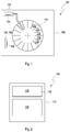
- Figure 1 shows a perspective view of a system 100 comprising a laboratory instrument 102 for processing a reagent or a biological sample, at least one consumable 104 and a RFID tag 106 associated with the consumable 104.
- the consumable 104 may be at least one element selected from the group consisting of: reagent vessel, biological sample vessel, pipetting tip, and cuvette.
- the consumable is a reagent vessel 108 and the RFID tag may adhere to a side of the reagent vessel 108.
- the laboratory instrument 102 comprises a rotor 110.
- the rotor 110 comprises a plurality of compartments 112 configured to receive the reagent vessel 108 or a plurality of reagent vessels 108.
- FIG. 2 shows an enlarged view of the RFID tag 106 as used in connection with the disclosed method / system.
- the RFID tag 106 comprises a memory 114.
- the memory 114 is separated into at least two parts as will be explained in further detail below.
- the memory 114 comprises a user memory 116, which is configured to store user data, and a system memory 118, which is configured to store system data.
- the memory 114 may be organized based on the ISO standards ISO/IEC 15693. Direct read/write access to the user memory 116 is possible depending on the related write protection conditions.
- all required information is stored such as unique identifier, write protection, access control information, passwords, application family identifier and electronic article surveillance.
- the system memory 118 cannot be directly accessed.
- the unique identifier cannot be altered and guarantees the uniqueness of each RFID tag.
- the system memory 118 is password protected which enables the addressed RFID tag 106 to be set in a mode where the electronic article surveillance status and the application family identifier value can only be changed if the correct password is transmitted to the RFID tag within predetermined commands.
- the system memory 118 comprises special function bytes 120.
- the laboratory instrument 102 is configured to write temporary data into the system memory 118.
- the temporary data are associated with the process to be carried out by the laboratory instrument 102.
- the special function bytes 120 are configured to temporary store the temporary data.
- the temporary data are associated with the process steps.
- the laboratory instrument 102 writes the temporary data into the system memory 118 each time the consumable and thus one of the process steps are cleared when the consumable terminates one of the process steps.
- the laboratory instrument 102 further comprises a control unit 122.
- the control unit 122 is configured to write the temporary data into the system memory 118.
- the control unit 122 is also configured to read the temporary data written into the system memory 118.
- the control unit 122 comprises an antenna 124 such as a RFID reader antenna configured to read the temporary data.
- the control unit 122 is configured to issue a command for transmitting the temporary data written into the system memory 118.
- the temporary data are transmitted from the RFID tag 106 of the consumable 104 and received by the antenna 124.
- Figures 3-5 show possible operations of the system 100.
- the laboratory instrument 102 comprises the rotor 110.
- the rotor 110 comprises the plurality of compartments 112 for receiving a plurality of reagent vessels 108.
- the temporary data may comprise information on a target position of the reagent vessel 108 on the rotor 110. With other words, the temporary data include information on which location a reagent vessel 108 is to be disposed.
- the target position is associated with one of the compartments 112.
- the control unit 122 is configured to check whether an actual position of the reagent vessel 108 on the rotor 110 corresponds to the target position.
- control unit 122 is configured to check whether the actual position of the vessel 108 and rotor 112 corresponds to the target position based on a quality of a signal transmitted from the RFID tag 106 of the reagent vessel 108 to the control unit 122 as will be explained in more detail below.
- FIGs 3 shows a schematic illustration of the operation of the system.
- the rotor 110 and the compartments 112 are shown in a simplified manner in Figure 3 .
- the compartments 112 represent different rotor positions.
- a first rotor position 126 is shown at the left
- a second rotor position 128 is shown in the middle
- a third rotor position 130 is shown at the right.
- the plurality of compartments 112 may represent more than three rotor positions such as 4, 5, 10, 20, 30 or even more.
- Further shown in Figure 3 are three reagent vessels 108, each one of which is stored in one of the compartments 112.
- the reagent vessels 108 are illustrated in a simplified manner such that only the system memories of the reagent vessels 108 are illustrated. Particularly, a first system memory 132 is shown at the first rotor position 126, a second system memory 134 is shown at the second rotor position 128 and a third system memory 136 is shown at the third rotor position 130.
- first system memory 132 temporary data are stored comprising information that the target position of this reagent vessel 108 is the first rotor position 126.
- temporary data are stored comprising information that the target position of this reagent vessel 108 is the second rotor position 128.
- temporary data are stored comprising information that the target position of this reagent vessel 108 is the third rotor position 130.
- a distance from the second rotor position 128 to the antenna 124 of the control unit 122 is closer than a distance from the first rotor position 126 or the third rotor position 130 to the antenna 124. If the control unit 122 issues a communication command for checking whether the reagent vessels 108 are arranged on their correct position, the control unit 122 may check the response signal strength. In the example shown in Figure 3 , the control unit 122 checks whether the reagent vessel 108 at the second rotor position 128 is at its correct position.
- the rotor 110 is rotated such that the second rotor position 128 faces the antenna 124.
- the control unit 122 issues a communication command to the reagent vessel 108 at the second rotor position 128.
- temporary data are stored comprising information that the target position of this reagent vessel 108 is the second rotor position 128 and the second system memory 134 is disposed at the second rotor position 128, the response signal transmitted to the antenna 124 comprises the full strength due to the shortest possible distance to the antenna 124.
- the control unit 122 determines a match of the special function bytes values of the second system memory 134 and the second rotor position 128. With other words, the control unit 122 determines that the actual position of the reagent vessel 108 at the second rotor position 128 corresponds to the target position thereof.
- Figure 4 shows a schematic illustration of the operation of the system. Particularly, Figure 4 shows the case where the reagent vessels 108 have been changed such that the second system memory 134 is disposed at the third rotor position 130 while the third system memory 136 is disposed at the second rotor position 128.
- the control unit 122 checks whether the reagent vessel 108 at the second rotor position 128 is at its correct position. Accordingly, the rotor 110 is rotated such that the second rotor position 128 faces the antenna 124. The control unit 122 issues a communication command to the reagent vessel 108 at the second rotor position 128.
- the control unit 122 determines a mismatch of the special function bytes values of the second system memory 134 and the second rotor position 128. With other words, the control unit 122 determines that the actual position of the reagent vessel 108 at the second rotor position 128 does not correspond to the target position thereof
- Figure 5 shows a schematic illustration of the operation of the system.
- the control unit 122 may be configured to identify a predetermined one of the reagent vessels 108 by means of issuing a specific command as will be explained in further detail.
- the rotor position id can be correlated to one of the RFID tags in the field without the use of any receive signal evaluation algorithms.
- the control unit 122 issues the command "I want to communicate with RFID tag 106 on the second rotor position 128".
- the control unit 122 communicates with the second system memory 134 shown in the middle provided the actual position thereof corresponds to the target position thereof.
- the antenna 124 will receive a response signal exclusively from the RFID tag on the second rotor position 128.
Landscapes
- Engineering & Computer Science (AREA)
- Physics & Mathematics (AREA)
- Health & Medical Sciences (AREA)
- General Physics & Mathematics (AREA)
- Theoretical Computer Science (AREA)
- General Health & Medical Sciences (AREA)
- Toxicology (AREA)
- Computer Hardware Design (AREA)
- General Engineering & Computer Science (AREA)
- Primary Health Care (AREA)
- Epidemiology (AREA)
- Medical Informatics (AREA)
- Public Health (AREA)
- Computer Security & Cryptography (AREA)
- Microelectronics & Electronic Packaging (AREA)
- Electromagnetism (AREA)
- Artificial Intelligence (AREA)
- Computer Vision & Pattern Recognition (AREA)
- Computer Networks & Wireless Communication (AREA)
- Automatic Analysis And Handling Materials Therefor (AREA)
Abstract
Description
- The disclosed method / system relates to a method for storing temporary data in a memory of an RFID tag associated with a consumable of a laboratory instrument and system comprising a laboratory instrument, a consumable and an RFID tag.
- Laboratory instruments in the field of the disclosed method / system process reagents or biological sample. With such laboratory instruments, RFID tags are provided on reagent containers for automatic analyzers. The RFID tag comprises a memory divided into two parts. The first part is the so called user memory and the second part is the so called system memory or configuration area. Within the user memory, the user data are stored. Direct read or write access to this part of the memory is possible depending on the related write protection conditions. Within the system memory, all required information is stored, such as the unique identifier (UID), write protection, access control information, passwords, application family identifier (AFI) and electronic article surveillance (EAS). This memory area cannot be directly accessed.
- It is known to store temporary dynamic process/workflow data in a data base. If needed, the UID is read from the RFID tag and compared to stored data in the data base or used as pointer/identifier/reference number to look up. The user memory part on the RFID tag is used for more permanent data like reagent information, expiration date, analyzer used and the like.
- It is also known to use RFID tags on in vitro diagnostics containers. The UID or any functional equivalent identifier is assigned and programmed by the RFID integrated circuit manufacturer. Thus, the UID or any functional equivalent identifier cannot be altered and guarantees the uniqueness of each label. Regarding the UID or any functional equivalent identifier, password protected EAS and AFI functionality, the EAS/AFI password enables the addressed label to be set in a mode where the EAS status and the AFI value can only be changed if the correct EAS/AFI password is transmitted to the label within the mentioned commands. It is to be noted that password protection is optional. Some RFID integrated circuits have AFI and data storage format identifier (DSFID) without password protection. Temporarily dynamic process/workflow data is usually stored in the user memory part on the RFID tag. For example, the information on which analyzer a reagent is used is written to the user memory part.
- However, the communication and checking/looking-up with the database is slowing down the workflow. Depending on the amount and velocity of involved mechanics of for examples reagent storage or sample transport, the communication with a database could thwart the process, especially if one thinks of extending the idea to large pre- or post-analytic storage or transport units. In addition to mechanical factors also electrical factors could thwart the process such as- access time to data base and real time network availability.
- If the user memory part of the RFID tag is used, the whole data concept of information on a tag will be affected and memory capacity for more permanent information like reagent fluid content or expiration date will be reduced. In addition, during production of reagents and reagent container with the tag, the exact storage area needs to be defined and has to be kept free for dynamic/temporary data. This will lead to a huge effort in agreement between different departments or companies that are stakeholders of the RFID data concept. Another drawback of using the user memory part for storing of temporary data is that this memory part is grouped in bigger sections, i.e. the so called blocks and/or sections. The memory area that needs to be read or written will be one or multiple block(s) depending on the data size and allocation. Another important drawback is caused due to the fact that the UID is stored in the system memory of the tag and any temporary data will be stored in the user memory part. Thus, it would need at least two reading commands to link the UID to these temporary data, which again slows down the workflow. In some cases, even more commands are necessary to access the special section/block on the tag to read the corresponding temporary data.
- Disclosed herein are a method for storing temporary data in a memory of a RFID tag associated with a consumable of a laboratory instrument for processing a reagent or biological sample and a system comprising an laboratory instrument for processing a reagent or biological sample, a consumable and a RFID tag associated with the consumable that provide an improved handling of RIFD tags associated with consumables of a laboratory instrument.
- Embodiments of the disclosed method / system for storing temporary data in a memory of a RFID tag associated with a consumable of a laboratory instrument for processing a reagent or biological sample and a system comprising an laboratory instrument for processing a reagent or biological sample, a consumable and a RFID tag associated with the consumable have the features of the independent claims. Particular embodiments, which may be realized in an isolated way or in any arbitrary combination, are disclosed in the dependent claims.
- As used in the following, the terms "have", "comprise" or "include" or any arbitrary grammatical variations thereof are used in a non-exclusive way. Thus, these terms may both refer to a situation in which, besides the feature introduced by these terms, no further features are present in the entity described in this context and to a situation in which one or more further features are present. As an example, the expressions "A has B", "A comprises B" and "A includes B" may both refer to a situation in which, besides B, no other element is present in A (i.e. a situation in which A solely and exclusively consists of B) and to a situation in which, besides B, one or more further elements are present in entity A, such as element C, elements C and D or even further elements.
- Further, it shall be noted that the terms "at least one", "one or more" or similar expressions indicating that a feature or element may be present once or more than once typically will be used only once when introducing the respective feature or element. In the following, in most cases, when referring to the respective feature or element, the expressions "at least one" or "one or more" will not be repeated, non-withstanding the fact that the respective feature or element may be present once or more than once.
- Further, as used in the following, the terms "particularly", "more particularly", "specifically", "more specifically" or similar terms are used in conjunction with features of particular or alternative embodiment(s), without restricting alternative possibilities. The disclosed method / system may, as the skilled person will recognize, be performed by using alternative features. Similarly, features introduced by "in an embodiment of the disclosed method / system " or similar expressions are intended to be additional and/or alternative features, without any restriction regarding alternative embodiments, without any restrictions regarding the scope of the disclosed method / system and without any restriction regarding the possibility of combining the features introduced in such way with other optional or non-optional features of the disclosed method / system.
- According to the disclosed method / system, a method for storing temporary data in a memory of a RFID tag associated with a consumable of a laboratory instrument for processing a reagent or biological sample is disclosed. The method comprises:
- providing the RFID tag associated with the consumable, wherein the RFID tag comprises a memory, wherein the memory comprises a user memory, which is configured to store user data, and a system memory, which is configured to store system data, and
- the laboratory instrument writing the temporary data into the system memory, wherein the temporary data are associated with a process to be carried out by the laboratory instrument.
- The term "system memory" is synonymously used with the term "configuration area".
- The term "temporary data" as used herein refers to dynamic data that are stored in or written into the system memory and which may be also cleared therefrom during a process of the laboratory instrument.
- The term "laboratory instrument" as used herein encompasses any apparatus or apparatus component operable to execute one or more processing steps/workflow steps on one or more biological samples and/or reagents. The term "processing step" thereby refers to physically executed processing steps such as centrifugation, aliquotation, sample analysis and the like. The term "instrument" covers pre-analytical sample work-cells, post-analytical sample work-cells and also analytical work-cells.
- The term "reagents" as used herein refers to reagents necessary for performing the analysis of analytes and include reagents for sample preparation, control reagents, reagents for reacting with the analyte to obtain a detectable signal, and/or reagents necessary for detecting the analyte. Such reagents may include reagents for isolating an analyte and/or reagents for processing a sample and/or reagents for reacting with an analyte to obtain a detectable signal and/or washing reagents and/or diluents. Such reagents may be provided in a reagent vessel or reagent cassette. A reagent cassette can refer to a container comprising a liquid or suspension of reagents. Or a reagent cassette can be a holder for holding containers comprising a liquid or a suspension of reagents.
- As the temporary data associated with a process to be carried out by the laboratory instrument are written into the system memory, only one operation and command, respectively, is needed to identify and read the data as compared to two operations and commands, respectively, needed if data are stored in the user memory. By using only a single command, such as "Get System Information" as defined in ISO/IEC 15693-3, the UID as well as the stored temporary data are transmitted from the RFID tag to a RFID reader resulting in a very fast identification of the UID plus the dynamic or temporary data. Thus, a lot of communication time may be saved and the process carried out by the laboratory instrument is accelerated if compared to a process in which data have to be read from the user memory.
- The system memory may comprise special function bytes, wherein the special function bytes are used to store the temporary data.
- The term "special function bytes" as used herein refers to the bytes of the system memory such as application family identifier (AFI) or data storage format identifier (DSFID). A memory is organized in a specific manner. For example, a RFID Chip Memory organization may be based on the ISO standards ISO/IEC 15693. The respective 1024 bit electrically erasable programmable read only memory (EEPROM) is divided into 32 blocks. A block is the smallest access unit. Each block consists of 4 bytes (1 block = 32 bits). Bit 0 in each byte represents the least significant bit (LSB) and bit 7 the most significant bit (MSB), respectively. Thereby, the UID as well as the value of these special function bytes is transmitted from the RFID tag to the RFID reader resulting in a very fast identification of UID plus dynamic data. Needless to say, there are integrated circuits with different memory sizes out in the market. There are also integrated circuits with different memory blocks out in the market. Further, there are integrated circuits with different memory blocks widths out in the market, e.g. 32 bit or 64 bit block width.
- The consumable may be at least one element selected from the group consisting of: reagent vessel, biological sample vessel, pipetting tip, and cuvette. Thus, the method may be applied to every consumable used with a laboratory instrument.
- The process may comprise process steps, wherein the temporary data are associated with the process steps, wherein the temporary data are written into the system memory each time the consumable enters one of the process steps and are cleared when the consumable terminates one of the process steps. Thus, the data may be written into and cleared from the system memory in a fast or dynamic manner such that the process is accelerated. Further, no communication with an external data system is necessary.
- The temporary data may comprise information on the consumable. Thus, the laboratory instrument may be informed on the consumable and manage the process to be carried out.
- The laboratory instrument may comprise a control unit, wherein the control unit writes the temporary data into the system memory. As a laboratory instrument usually comprises a control unit, this control unit may be adapted to write the temporary data into the system memory. Thus, no further device is necessary for the writing process but the components present within the laboratory instrument may be adapted or modified to fulfil the writing function.
- The control unit may read the temporary data written into the system memory. As a laboratory instrument usually comprises a control unit, this control unit may be adapted to read the temporary data from the system memory. Thus, no further device is necessary for the reading process but the components present within the laboratory instrument may be adapted or modified to fulfil the reading function.
- The temporary data written into the system memory may be transmitted to the control unit by means of a command issued from the control unit. Particularly, only one single command is needed to identify the RFID tag and read the temporary data as compared to two commands needed if data are stored in the user memory. By using only a single command, such as "Get System Information" as defined in ISO/IEC 15693-3, the UID as well as the stored temporary data are transmitted from the RFID tag to a RFID reader of the control unit resulting in a very fast identification of the UID plus the dynamic or temporary data. It is to be noted that a RFID reader is capable to read and write data. Thus, a lot of communication time may be saved and the process carried out by the laboratory instrument is accelerated if compared to a process in which data have to be read from the user memory.
- The information may include at least one element selected from the group comprising: target position of the consumable, actual position of the consumable, state of the consumable, type of the consumable and content of the consumable. Thus, a lot of information may be stored in the system memory. The actual position of item is determined by other means and is initially stored into these special bytes. In case of a power down or manually reloading, the target position in the memory should match the one retrieved with other means, e.g. encoder of the instrument.
- The consumable may be a vessel configured to store a reagent or biological sample. For example, the vessel may be a sample tube, reagent cassette or a reagent container. The laboratory instrument may comprise a rotor comprising a plurality of compartments configured to receive the vessel. With other words, each of the plurality of compartments is configured to receive a vessel. Thus, the rotor basically provides a plurality of potential positions for a vessel. The temporary data may comprise information on a target and/or actual position of the vessel on the rotor, wherein the target position is associated with one of the compartments. Thus, the position where the vessel is to be disposed and/or the current position of the vessel may be stored as information within the system memory. Accordingly, a dynamic tracking of the vessel is possible.
- The control unit may check whether an actual position of the vessel on the rotor corresponds to the target position. Thus, the control unit checks whether the vessel is disposed at its correct position on the rotor.
- The control unit may check whether the actual position of the vessel on the rotor corresponds to the target position based on a quality of a signal transmitted from RFID tag of the vessel to the control unit. As the signal quality and strength, respectively, decreases with increasing distance of the RFID tag to the RDID reader, a deviation of the actual position from the target position may be detected if the actual signal does not correspond to the target signal. Thus, by means of a simple comparison of the actual signal with a target signal, it may be detected whether the actual positon corresponds to the target positon or not.
- A plurality of consumables may be provided, wherein the control unit identifies and/or locates one of the consumables by means of issuing a command and receiving a response signal from the one consumable. Locating works in conjunction by matching with other sensors or by checking the sequence of consecutive position reads. Thus, the command ensures that only a response signal is received from that consumable with which the control unit wants to communicate. Accordingly, the control unit is prevented from receiving any information from other consumables than a target consumable.
- Further, according to the disclosed method / system, a system comprising a laboratory instrument for processing a reagent or biological sample, a consumable and a RFID tag associated with the consumable is disclosed. The RFID tag comprises a memory, wherein the memory comprises a user memory, which is configured to store user data, and a system memory, which is configured to store system data of the integrated circuit, wherein the laboratory instrument is configured to carry out each of the methods of the disclosed method / system. As the temporary data associated with a process to be carried out by the laboratory instrument are writable into the system memory, only one operation and command, respectively, is needed to identify and read the data as compared to two operations and commands, respectively, needed if data are stored in the user memory. By using only a single command, such as "Get System Information" as defined in ISO/IEC 15693-3, the UID as well as the stored temporary data are transmitted from the RFID tag to a RFID reader resulting in a very fast identification of the UID plus the dynamic or temporary data. Thus, a lot of communication time may be saved and the process carried out by the laboratory instrument is accelerated if compared to a process in which data have to be read from the user memory.
- In the inventive system, temporary data may be written in the system memory.
- The system memory may comprise special function bytes, wherein the special function bytes are configured to temporary store the temporary data. Thereby, the UID as well as the value of these special function bytes is transmitted from the RFID tag to the RFID reader resulting in a very fast identification of UID plus dynamic data.
- The consumable may be at least one element selected from the group consisting of: reagent vessel, biological sample vessel, pipetting tip, and cuvette. Thus, the system may use every consumable used with a laboratory instrument.
- The temporary data may be associated with a process to be carried out by the laboratory instrument. Particularly, the process may comprise process steps, wherein the temporary data are associated with the process steps, wherein the laboratory instrument is configured to write the temporary data into the system memory each time the consumable enters one of the process steps and are cleared when the consumable terminates one of the process steps. Thus, the data may be written into and cleared from the system memory in a fast or dynamic manner such that the process is accelerated. Further, no communication with an external data system is necessary.
- The temporary data may comprise information on the consumable. Thus, the laboratory instrument may be informed on the consumable and manage the process to be carried out.
- The laboratory instrument may comprise a control unit, wherein the control unit is configured to write the temporary data into the system memory. As a laboratory instrument usually comprises a control unit, this control unit may be adapted to write the temporary data into the system memory. Thus, no further device is necessary for the writing process but the components present within the laboratory instrument may be adapted or modified to fulfil the writing function.
- The control unit may be configured to read the temporary data written into the system memory. As a laboratory instrument usually comprises a control unit, this control unit may be adapted to read the temporary data from the system memory. Thus, no further device is necessary for the reading process but the components present within the laboratory instrument may be adapted or modified to fulfil the reading function.
- The control unit may be configured to issue a command for transmitting the temporary data written into the system memory. Particularly, only one single command is needed to identify the RFID tag and read the temporary data as compared to two commands needed if data are stored in the user memory. By using only a single command, such as "Get System Information" as defined in ISO/IEC 15693-3, the UID as well as the stored temporary data are transmitted from the RFID tag to a RFID reader of the control unit resulting in a very fast identification of the UID plus the dynamic or temporary data. Thus, a lot of communication time may be saved and the process carried out by the laboratory instrument is accelerated if compared to a process in which data have to be read from the user memory.
- The control unit may comprise an antenna configured to read the temporary data. Thus, a simple receiver for receiving the transmitted signal is provided.
- The information may include at least one element selected from the group comprising: target position of the consumable, actual position of the consumable, state of the consumable, type of the consumable and content of the consumable. Thus, a lot of information may be stored in the system memory.
- The consumable may be a vessel configured to store a reagent or biological sample. For example, the vessel may be a sample tube, reagent cassette or a reagent container. The laboratory instrument may comprise a rotor comprising a plurality of compartments configured to receive the vessel. With other words, each of the plurality of compartments is configured to receive a vessel. Thus, the rotor basically provides a plurality of potential positions for a vessel. The temporary data may comprise information on a target and/or actual position of the vessel on the rotor, wherein the target position is associated with one of the compartments. Thus, the position where the vessel is to be disposed and/or the current position of the vessel may be stored as information within the system memory. Accordingly, a dynamic tracking of the vessel is possible.
- The control unit may be configured to check whether an actual position of the vessel on the rotor corresponds to the target position. Thus, the control unit checks whether the vessel is disposed at its correct position on the rotor.
- The control unit may be configured to check whether the actual position of the vessel on the rotor corresponds to the target position based on a quality of a signal transmitted from the RFID tag of the vessel to the control unit. As the signal quality and strength, respectively, decreases with increasing distance of the RFID tag to the RDID reader, a deviation of the actual position from the target position may be detected if the actual signal does not correspond to the target signal. Thus, by means of a simple comparison of the actual signal with a target signal, it may be detected whether the actual positon corresponds to the target positon or not.
- The inventive system may further comprise a plurality of consumables, wherein the control unit is configured to identify one of the consumables by means of issuing a command and receiving a response signal from the one consumable. Thus, the command ensures that only a response signal is received from that consumable with which the control unit wants to communicate. Accordingly, the control unit is prevented from receiving any information from other consumables than a target consumable.
- The disclosed method / system further discloses and proposes a computer program including computer-executable instructions for performing the method according to the disclosed method / system in one or more of the embodiments enclosed herein when the program is executed on a computer or computer network. Specifically, the computer program may be stored on a computer-readable data carrier. Thus, specifically, one, more than one or even all of the method steps as indicated above may be performed by using a computer or a computer network, preferably by using a computer program.
- The disclosed method / system further discloses and proposes a computer program product having program code means, in order to perform the method according to the disclosed method / system in one or more of the embodiments enclosed herein when the program is executed on a computer or computer network. Specifically, the program code means may be stored on a computer-readable data carrier.
- Further, the invention discloses and proposes a data carrier having a data structure stored thereon, which, after loading into a computer or computer network, such as into a working memory or main memory of the computer or computer network, may execute the method according to one or more of the embodiments disclosed herein.
- The invention further proposes and discloses a computer program product with program code means stored on a machine-readable carrier, in order to perform the method according to one or more of the embodiments disclosed herein, when the program is executed on a computer or computer network. As used herein, a computer program product refers to the program as a tradable product. The product may generally exist in an arbitrary format, such as in a paper format, or on a computer-readable data carrier. Specifically, the computer program product may be distributed over a data network.
- Finally, the invention proposes and discloses a modulated data signal which contains instructions readable by a computer system or computer network, for performing the method according to one or more of the embodiments disclosed herein.
- Preferably, referring to the computer-implemented aspects of the invention, one or more of the method steps or even all of the method steps of the method according to one or more of the embodiments disclosed herein may be performed by using a computer or computer network. Thus, generally, any of the method steps including provision and/or manipulation of data may be performed by using a computer or computer network. Generally, these method steps may include any of the method steps, typically except for method steps requiring manual work, such as providing the samples and/or certain aspects of performing the actual measurements.
- Specifically, the disclosed method / system further discloses:
- A computer or computer network comprising at least one processor, wherein the processor is adapted to perform the method according to one of the embodiments described in this description,
- a computer loadable data structure that is adapted to perform the method according to one of the embodiments described in this description while the data structure is being executed on a computer,
- a computer program, wherein the computer program is adapted to perform the method according to one of the embodiments described in this description while the program is being executed on a computer,
- a computer program comprising program means for performing the method according to one of the embodiments described in this description while the computer program is being executed on a computer or on a computer network,
- a computer program comprising program means according to the preceding embodiment, wherein the program means are stored on a storage medium readable to a computer,
- a storage medium, wherein a data structure is stored on the storage medium and wherein the data structure is adapted to perform the method according to one of the embodiments described in this description after having been loaded into a main and/or working storage of a computer or of a computer network, and
- a computer program product having program code means, wherein the program code means can be stored or are stored on a storage medium, for performing the method according to one of the embodiments described in this description, if the program code means are executed on a computer or on a computer network.
- Summarizing the findings of the disclosed method / system, the following embodiments are disclosed:
- Embodiment 1: Method for storing temporary data in a memory of an RFID tag associated with a consumable of a laboratory instrument for processing a reagent or biological sample, comprising:
- providing the RFID tag associated with the consumable, wherein the RFID tag comprises a memory, wherein the memory comprises a user memory, which is configured to store user data, and a system memory, which is configured to store system data of the integrated circuit, and
- the laboratory instrument writing the temporary data into the system memory, wherein the temporary data are associated with a process to be carried out by the laboratory instrument.
- Embodiment 2: Method according to the preceding embodiment, wherein the system memory comprises special function bytes, wherein the special function bytes are used to store the temporary data.
- Embodiment 3: Method according to any preceding embodiment, wherein the consumable is at least one element selected from the group consisting of: reagent vessel, biological sample vessel, pipetting tip, and cuvette.
- Embodiment 4: Method according to any preceding embodiment, wherein the process comprises process steps, wherein the temporary data are associated with the process steps, wherein the temporary data are written into the system memory each time the consumable enters one of the process steps and are cleared when the consumable terminates one of the process steps.
- Embodiment 5: Method according to any one of the two preceding embodiments, wherein the temporary data comprise information on the consumable.
- Embodiment 6: Method according to any preceding embodiment, wherein the laboratory instrument comprises a control unit, wherein the control unit writes the temporary data into the system memory.
- Embodiment 7: Method according to the preceding embodiment, wherein the control unit reads the temporary data written into the system memory.
- Embodiment 8: Method according to the preceding embodiment, wherein the temporary data written into the system memory are transmitted to the control unit by means of a command issued from the control unit.
- Embodiment 9: Method according to any one of embodiments 5 to 8, wherein the information includes at least one element selected from the group comprising: target position of the consumable, actual position of the consumable, state of the consumable, type of the consumable and content of the consumable.
- Embodiment 10: Method according to any one of embodiments 5 to 9, wherein the consumable is a vessel configured to store a reagent or biological sample, wherein the laboratory instrument comprises a rotor comprising a plurality of compartments configured to receive the vessel, wherein the temporary data comprise information on a target and/or actual position of the vessel on the rotor, wherein the target position is associated with one of the compartments.
- Embodiment 11: Method according to the preceding embodiment, wherein the control unit checks whether an actual position of the vessel on the rotor corresponds to the target position.
- Embodiment 12: Method according to the preceding embodiment, wherein the control unit checks whether the actual position of the vessel on the rotor corresponds to the target position based on a quality of a signal transmitted from the integrated circuit of the vessel to the control unit.
- Embodiment 13: Method according to any one of embodiments 5 to 12, wherein a plurality of consumables is provided, wherein the control unit identifies and/or locates one of the consumables by means of issuing a command and receiving a response signal from the one consumable.
- Embodiment 14: System comprising a laboratory instrument for processing a reagent or biological sample, a consumable and a RFID tag associated with the consumable, wherein the RFID tag comprises a memory, wherein the memory comprises a user memory, which is configured to store user data, and a system memory, which is configured to store system data of the integrated circuit, wherein the laboratory instrument is configured to carry out each of the methods according to any preceding embodiment.
- Embodiment 15: System according to the preceding embodiment, wherein temporary data are written in the system memory.
- Embodiment 16: System according to any one of embodiments 14 to 15, wherein the system memory comprises special function bytes, wherein the special function bytes are configured to temporary store the temporary data.
- Embodiment 17: System according to any one of embodiments 14 to 16, wherein the consumable is at least one element selected from the group consisting of: reagent vessel, biological sample vessel, pipetting tip, and cuvette.
- Embodiment 18: System according to any one of embodiments 14 to 17, wherein the process comprises process steps, wherein the temporary data are associated with the process steps, wherein the laboratory instrument is configured to write the temporary data into the system memory each time the consumable enters one of the process steps and are cleared when the consumable terminates one of the process steps. Otherwise/with faulty termination of the process, it can be used to restore the original correct configuration/loading.
- Embodiment 19: System according to any one of the two preceding embodiments, wherein the temporary data comprise information on the consumable.
- Embodiment 20: System according to any one of embodiments 14 to 19, wherein the laboratory instrument comprises a control unit, wherein the control unit is configured to write the temporary data into the system memory.
- Embodiment 21: System according to the preceding embodiment, wherein the control unit is configured to read the temporary data written into the system memory.
- Embodiment 22: System according to the preceding embodiment, wherein the control unit is configured to issue a command for transmitting the temporary data written into the system memory.
- Embodiment 23: System according to any of the two preceding embodiments, wherein the control unit comprises an antenna configured to read the temporary data.
- Embodiment 24: System according to any one of embodiments 19 to 23, wherein the information includes at least one element selected from the group consisting of: target position of the consumable, actual position of the consumable, state of the consumable, type of the consumable and content of the consumable.
- Embodiment 25: System according to any one of embodiments 19 to 24, wherein the consumable is a vessel configured to store a reagent or biological sample, wherein the laboratory instrument comprises a rotor comprising a plurality of compartments configured to receive the vessel, wherein the temporary data comprise information on a target position of the vessel on the rotor, wherein the target position is associated with one of the compartments.
- Embodiment 26: System according to the preceding embodiment, wherein the control unit is configured to check whether an actual position of the vessel on the rotor corresponds to the target position.
- Embodiment 27: System according to the preceding embodiment, wherein the control unit is configured to check whether the actual position of the vessel on the rotor corresponds to the target position based on a quality of a signal transmitted from the integrated circuit of the vessel to the control unit.
- Embodiment 28: System according to any one of embodiments 19 to 27, further comprising a plurality of consumables, wherein the control unit is configured to identify one of the consumables by means of issuing a command and receiving a response signal from the one consumable.
- Further features and embodiments of the invention will be disclosed in more detail in the subsequent description of embodiments, preferably in conjunction with the dependent claims. Therein, the respective features may be realized in an isolated fashion as well as in any arbitrary feasible combination, as a skilled person will realize. The embodiments are schematically depicted in the figures. Therein, identical reference numbers in these figures refer to identical elements or functionally identical elements.
- In the figures:
-
Figure 1 shows a perspective view of a system according to the disclosed method / system, -
Figure 2 shows an enlarged view of an RIFD tag of the system, -
Figure 3 shows a schematic illustration of the operation of the system, -
Figure 4 shows a schematic illustration of the operation of the system, -
Figure 5 shows a schematic illustration of the operation of the system. -
Figure 1 shows a perspective view of asystem 100 comprising alaboratory instrument 102 for processing a reagent or a biological sample, at least one consumable 104 and aRFID tag 106 associated with the consumable 104. The consumable 104 may be at least one element selected from the group consisting of: reagent vessel, biological sample vessel, pipetting tip, and cuvette. In the present embodiment, the consumable is a reagent vessel 108 and the RFID tag may adhere to a side of the reagent vessel 108. Thelaboratory instrument 102 comprises arotor 110. Therotor 110 comprises a plurality ofcompartments 112 configured to receive the reagent vessel 108 or a plurality of reagent vessels 108. -
Figure 2 shows an enlarged view of theRFID tag 106 as used in connection with the disclosed method / system. TheRFID tag 106 comprises amemory 114. Thememory 114 is separated into at least two parts as will be explained in further detail below. Particularly, thememory 114 comprises auser memory 116, which is configured to store user data, and asystem memory 118, which is configured to store system data. For example, thememory 114 may be organized based on the ISO standards ISO/IEC 15693. Direct read/write access to theuser memory 116 is possible depending on the related write protection conditions. Within thesystem memory 118, all required information is stored such as unique identifier, write protection, access control information, passwords, application family identifier and electronic article surveillance. Thesystem memory 118 cannot be directly accessed. Particularly, the unique identifier cannot be altered and guarantees the uniqueness of each RFID tag. As mentioned, thesystem memory 118 is password protected which enables the addressedRFID tag 106 to be set in a mode where the electronic article surveillance status and the application family identifier value can only be changed if the correct password is transmitted to the RFID tag within predetermined commands. - Further, the
system memory 118 comprisesspecial function bytes 120. Thelaboratory instrument 102 is configured to write temporary data into thesystem memory 118. The temporary data are associated with the process to be carried out by thelaboratory instrument 102. According to the disclosed method / system, thespecial function bytes 120 are configured to temporary store the temporary data. The temporary data are associated with the process steps. Thelaboratory instrument 102 writes the temporary data into thesystem memory 118 each time the consumable and thus one of the process steps are cleared when the consumable terminates one of the process steps. - As shown in
Figure 1 , for this purpose, thelaboratory instrument 102 further comprises acontrol unit 122. Thecontrol unit 122 is configured to write the temporary data into thesystem memory 118. Thecontrol unit 122 is also configured to read the temporary data written into thesystem memory 118. For this purpose, thecontrol unit 122 comprises anantenna 124 such as a RFID reader antenna configured to read the temporary data. Further, thecontrol unit 122 is configured to issue a command for transmitting the temporary data written into thesystem memory 118. Thus, when thecontrol unit 122 issues a command, the temporary data are transmitted from theRFID tag 106 of the consumable 104 and received by theantenna 124. -
Figures 3-5 show possible operations of thesystem 100. As mentioned above, thelaboratory instrument 102 comprises therotor 110. Therotor 110 comprises the plurality ofcompartments 112 for receiving a plurality of reagent vessels 108. The temporary data may comprise information on a target position of the reagent vessel 108 on therotor 110. With other words, the temporary data include information on which location a reagent vessel 108 is to be disposed. Thus, the target position is associated with one of thecompartments 112. Thecontrol unit 122 is configured to check whether an actual position of the reagent vessel 108 on therotor 110 corresponds to the target position. For example, thecontrol unit 122 is configured to check whether the actual position of the vessel 108 androtor 112 corresponds to the target position based on a quality of a signal transmitted from theRFID tag 106 of the reagent vessel 108 to thecontrol unit 122 as will be explained in more detail below. A distance from the second system memory -
Figures 3 shows a schematic illustration of the operation of the system. For explanatory reasons, therotor 110 and thecompartments 112 are shown in a simplified manner inFigure 3 . Thecompartments 112 represent different rotor positions. InFigure 3 , afirst rotor position 126 is shown at the left, asecond rotor position 128 is shown in the middle and athird rotor position 130 is shown at the right. Needless to say, the plurality ofcompartments 112 may represent more than three rotor positions such as 4, 5, 10, 20, 30 or even more. Further shown inFigure 3 are three reagent vessels 108, each one of which is stored in one of thecompartments 112. The reagent vessels 108 are illustrated in a simplified manner such that only the system memories of the reagent vessels 108 are illustrated. Particularly, afirst system memory 132 is shown at thefirst rotor position 126, asecond system memory 134 is shown at thesecond rotor position 128 and athird system memory 136 is shown at thethird rotor position 130. In thefirst system memory 132, temporary data are stored comprising information that the target position of this reagent vessel 108 is thefirst rotor position 126. In thesecond system memory 134, temporary data are stored comprising information that the target position of this reagent vessel 108 is thesecond rotor position 128. In thethird system memory 136, temporary data are stored comprising information that the target position of this reagent vessel 108 is thethird rotor position 130. A distance from thesecond rotor position 128 to theantenna 124 of thecontrol unit 122 is closer than a distance from thefirst rotor position 126 or thethird rotor position 130 to theantenna 124. If thecontrol unit 122 issues a communication command for checking whether the reagent vessels 108 are arranged on their correct position, thecontrol unit 122 may check the response signal strength. In the example shown inFigure 3 , thecontrol unit 122 checks whether the reagent vessel 108 at thesecond rotor position 128 is at its correct position. Accordingly, therotor 110 is rotated such that thesecond rotor position 128 faces theantenna 124. Thecontrol unit 122 issues a communication command to the reagent vessel 108 at thesecond rotor position 128. As in thesecond system memory 134, temporary data are stored comprising information that the target position of this reagent vessel 108 is thesecond rotor position 128 and thesecond system memory 134 is disposed at thesecond rotor position 128, the response signal transmitted to theantenna 124 comprises the full strength due to the shortest possible distance to theantenna 124. Thereby, thecontrol unit 122 determines a match of the special function bytes values of thesecond system memory 134 and thesecond rotor position 128. With other words, thecontrol unit 122 determines that the actual position of the reagent vessel 108 at thesecond rotor position 128 corresponds to the target position thereof. -
Figure 4 shows a schematic illustration of the operation of the system. Particularly,Figure 4 shows the case where the reagent vessels 108 have been changed such that thesecond system memory 134 is disposed at thethird rotor position 130 while thethird system memory 136 is disposed at thesecond rotor position 128. In the example shown inFigure 4 , thecontrol unit 122 checks whether the reagent vessel 108 at thesecond rotor position 128 is at its correct position. Accordingly, therotor 110 is rotated such that thesecond rotor position 128 faces theantenna 124. Thecontrol unit 122 issues a communication command to the reagent vessel 108 at thesecond rotor position 128. As in thesecond system memory 134, temporary data are stored comprising information that the target position of this reagent vessel 108 is thesecond rotor position 128 and thesecond system memory 134 is disposed at thethird rotor position 130, the response signal transmitted to theantenna 124 comprises less strength than in the example shown inFigure 3 due to the longer distance to theantenna 124. Thereby, thecontrol unit 122 determines a mismatch of the special function bytes values of thesecond system memory 134 and thesecond rotor position 128. With other words, thecontrol unit 122 determines that the actual position of the reagent vessel 108 at thesecond rotor position 128 does not correspond to the target position thereof -
Figure 5 shows a schematic illustration of the operation of the system. Particularly, thecontrol unit 122 may be configured to identify a predetermined one of the reagent vessels 108 by means of issuing a specific command as will be explained in further detail. In the shown example representing a multiple tagged item scenario, i.e. onereader antenna 124 with multiple RFID tags in the electro-magnetic field of the reader, the rotor position id can be correlated to one of the RFID tags in the field without the use of any receive signal evaluation algorithms. Furthermore by sending a command with the rotor position id as parameter only that specific RFID tag will respond saving a lot of communication time. For example, thecontrol unit 122 issues the command "I want to communicate withRFID tag 106 on thesecond rotor position 128". Then, thecontrol unit 122 communicates with thesecond system memory 134 shown in the middle provided the actual position thereof corresponds to the target position thereof. In this case, theantenna 124 will receive a response signal exclusively from the RFID tag on thesecond rotor position 128. -
- 100
- system
- 102
- laboratory instrument
- 104
- consumable
- 106
- RFID tag
- 108
- reagent vessel
- 110
- rotor
- 112
- compartment
- 114
- memory
- 116
- user memory
- 118
- system memory
- 120
- special function bytes
- 122
- control unit
- 124
- antenna
- 126
- first rotor position
- 128
- second rotor position
- 130
- third rotor position
- 132
- first system memory
- 134
- second system memory
- 136
- third system memory
Claims (15)
- Method for storing temporary data in a memory (114) of a RFID tag (106) associated with a consumable (104) of a laboratory instrument (102) for processing a reagent or biological sample, the method comprising- providing the RFID tag (106) associated with the consumable (104), wherein the RFID tag (106) comprises a memory (114), wherein the memory (114) comprises a user memory (116), which is configured to store user data, and a system memory (118), which is configured to store system data, and- the laboratory instrument (102) writing the temporary data into the system memory (118), wherein the temporary data are associated with a process to be carried out by the laboratory instrument (102).
- Method according to any preceding claim, wherein the system memory (118) comprises special function bytes (120), wherein the special function bytes (120) are used to store the temporary data.
- Method according to the preceding claim, wherein the process comprises process steps, wherein the temporary data are associated with the process steps, wherein the temporary data are written into the system memory (118) each time the consumable (104) enters one of the process steps and are cleared when the consumable (104) terminates one of the process steps.
- Method according to any one of the two preceding claims, wherein the temporary data comprise information on the consumable (104), wherein the information includes at least one element selected from the group comprising: target position of the consumable (104), actual position of the consumable (104), state of the consumable (104), type of the consumable (104) and content of the consumable (104).
- Method according to the preceding claim, wherein the control unit (122) reads the temporary data written into the system memory (118).
- Method according to any preceding claim, wherein the consumable (104) is a vessel (108) configured to store a reagent or biological sample, wherein the laboratory instrument (102) comprises a rotor (110) comprising a plurality of compartments (112) configured to receive the vessel (108), wherein the temporary data comprise information on a target and/or actual position of the vessel (108) on the rotor (110), wherein the target position is associated with one of the compartments (112).
- Method according to the preceding claim, wherein the control unit (122) checks whether an actual position of the vessel (108) on the rotor (110) corresponds to the target position.
- Method according to any one of claims 7 to 14, wherein a plurality of consumables (104) is provided, wherein the control unit (122) identifies and/or locates one of the consumables (104) by means of issuing a command and receiving a response signal from the one consumable (104).
- System (100) comprising a laboratory instrument (102) for processing a reagent or biological sample, a consumable (104) and a RFID tag (106) associated with the consumable (104), wherein the RFID tag (106) comprises a memory (114), wherein the memory (114) comprises a user memory (116), which is configured to store user data, and a system memory (118), which is configured to store system data of the integrated circuit, wherein the laboratory instrument (102) is configured to carry out each of the methods according to any preceding claim.
- System (100) according to the preceding claim, wherein temporary data are written in the system memory (118), particularly the system memory (118) comprises special function bytes (120), wherein the special function bytes (120) are configured to temporary store the temporary data.
- System (100) according to any one of claims 9 to 10, wherein the consumable (104) is at least one element selected from the group comprising: reagent vessel (108), biological sample vessel (108), pipetting tip, and cuvette.
- System (100) according to any one of claims 9 to 11, wherein the process comprises process steps, wherein the temporary data are associated with the process steps, wherein the laboratory instrument (102) is configured to write the temporary data into the system memory (118) each time the consumable (104) enters one of the process steps and are cleared when the consumable (104) terminates one of the process steps.
- System (100) according to any one of claims 9 to 12, wherein the laboratory instrument (102) comprises a control unit (122), wherein the control unit (122) is configured to write the temporary data into the system memory (118) and/or to read the temporary data written into the system memory (118).
- System (100) according to any one of claims 9 to 13, wherein the temporary data comprise information on the consumable (104), wherein the information includes at least one element selected from the group consisting of: target position of the consumable (104), actual position of the consumable (104), state of the consumable (104), type of the consumable (104) and content of the consumable (104)..
- System (100) according to any one of claims 9 to 14, wherein the consumable (104) is a vessel (108) configured to store a reagent or biological sample, wherein the laboratory instrument (102) comprises a rotor (110) comprising a plurality of compartments (112) configured to receive the vessel (108), wherein the temporary data comprise information on a target position of the vessel (108) on the rotor (110), wherein the target position is associated with one of the compartments (112).
Priority Applications (4)
| Application Number | Priority Date | Filing Date | Title |
|---|---|---|---|
| EP15201314.0A EP3182310B1 (en) | 2015-12-18 | 2015-12-18 | Method for storing temporary data in a memory of an rfid tag associated with a consumable of a laboratory instrument and system comprising a laboratory instrument, a consumable and an rfid tag |
| US15/380,136 US10185850B2 (en) | 2015-12-18 | 2016-12-15 | Method for storing temporary data in a memory of an RFID tag associated with a consumable of a laboratory instrument and system comprising a laboratory instrument, consumable and RFID tag |
| CN201611165924.2A CN107067053B (en) | 2015-12-18 | 2016-12-16 | Method and system for storing temporary data in the memory of an RFID tag |
| JP2016244229A JP6859089B2 (en) | 2015-12-18 | 2016-12-16 | A method for storing temporary data in the memory of RFID tags related to consumables of laboratory equipment, and systems with laboratory equipment, consumables and RFID tags. |
Applications Claiming Priority (1)
| Application Number | Priority Date | Filing Date | Title |
|---|---|---|---|
| EP15201314.0A EP3182310B1 (en) | 2015-12-18 | 2015-12-18 | Method for storing temporary data in a memory of an rfid tag associated with a consumable of a laboratory instrument and system comprising a laboratory instrument, a consumable and an rfid tag |
Publications (2)
| Publication Number | Publication Date |
|---|---|
| EP3182310A1 true EP3182310A1 (en) | 2017-06-21 |
| EP3182310B1 EP3182310B1 (en) | 2022-10-12 |
Family
ID=55027372
Family Applications (1)
| Application Number | Title | Priority Date | Filing Date |
|---|---|---|---|
| EP15201314.0A Active EP3182310B1 (en) | 2015-12-18 | 2015-12-18 | Method for storing temporary data in a memory of an rfid tag associated with a consumable of a laboratory instrument and system comprising a laboratory instrument, a consumable and an rfid tag |
Country Status (4)
| Country | Link |
|---|---|
| US (1) | US10185850B2 (en) |
| EP (1) | EP3182310B1 (en) |
| JP (1) | JP6859089B2 (en) |
| CN (1) | CN107067053B (en) |
Cited By (1)
| Publication number | Priority date | Publication date | Assignee | Title |
|---|---|---|---|---|
| EP3786965A1 (en) * | 2019-08-30 | 2021-03-03 | Dreampath Diagnostics | Device and method for automated management of containers of biological samples |
Families Citing this family (4)
| Publication number | Priority date | Publication date | Assignee | Title |
|---|---|---|---|---|
| US12484884B2 (en) * | 2017-10-09 | 2025-12-02 | Sakura Finetek U.S.A., Inc. | Tissue cassette reader |
| GB201720405D0 (en) * | 2017-12-07 | 2018-01-24 | Biosafe Sa | A bioprocessing system |
| US20240087691A1 (en) * | 2021-01-25 | 2024-03-14 | Leica Biosystems Nussloch Gmbh | Method and apparatus for processing sample |
| US12622682B2 (en) | 2022-11-16 | 2026-05-12 | Sakura Finetek U.S.A., Inc. | Tissue cassette reader |
Citations (4)
| Publication number | Priority date | Publication date | Assignee | Title |
|---|---|---|---|---|
| US20050159982A1 (en) * | 2003-07-17 | 2005-07-21 | Wayne Showalter | Laboratory instrumentation information management and control network |
| WO2008024471A2 (en) * | 2006-08-24 | 2008-02-28 | Kevin Lloyd | Laboratory information management using radio frequency identification |
| US20110022331A1 (en) * | 2009-07-27 | 2011-01-27 | Meso Scale Technologies, Llc | Assay Information Management Methods and Devices |
| US20150104796A1 (en) * | 2013-10-07 | 2015-04-16 | Eppendorf Ag | System comprising at least two laboratory instruments for instrument-controlled handling of a partial problem in a treatment process containing treatments of at least one laboratory sample, laboratory instrument and method |
Family Cites Families (14)
| Publication number | Priority date | Publication date | Assignee | Title |
|---|---|---|---|---|
| JP4106614B2 (en) | 2003-03-07 | 2008-06-25 | 株式会社エスアールエル | Sample rack and sample position confirmation system |
| US7333479B2 (en) * | 2003-06-30 | 2008-02-19 | Nokia Corporation | RFID system with packetized data storage in a mobile environment: methods, systems and program products |
| US8719053B2 (en) * | 2003-07-17 | 2014-05-06 | Ventana Medical Systems, Inc. | Laboratory instrumentation information management and control network |
| US7602284B2 (en) * | 2004-03-04 | 2009-10-13 | Ethicon, Inc. | Sterilizer cassette handling system with data link |
| KR100747601B1 (en) * | 2005-09-27 | 2007-08-08 | 한국전자통신연구원 | RFID Tag User Data Access System and Method |
| KR20070059266A (en) * | 2005-12-06 | 2007-06-12 | 삼성전자주식회사 | Image forming apparatus with security |
| US20110148570A1 (en) * | 2009-12-21 | 2011-06-23 | Christian Weidinger | Configuration RFID Circuit |
| US9289770B2 (en) * | 2010-02-27 | 2016-03-22 | Lear Lavi | RFID—specimen transport puck process features and process method to efficiently wand, rack, transport, track specimens in the laboratory |
| JP2011203115A (en) * | 2010-03-25 | 2011-10-13 | Sysmex Corp | Specimen analysis apparatus |
| CN102221613B (en) | 2010-03-18 | 2013-12-25 | 希森美康株式会社 | Sample analyzer |
| EP2638404B1 (en) * | 2010-11-12 | 2021-09-15 | Gen-Probe Incorporated | System and method for tracking items during a process |
| JP2012189379A (en) | 2011-03-09 | 2012-10-04 | Olympus Corp | Specimen examination system and specimen examination method |
| CN203705458U (en) * | 2013-11-12 | 2014-07-09 | 深圳市国赛生物技术有限公司 | Full-automatic quick testing system for single sample |
| EP2930663B1 (en) * | 2014-04-11 | 2020-07-01 | Nxp B.V. | Electronic circuit chip for an RFID tag with a read-only-once functionality |
-
2015
- 2015-12-18 EP EP15201314.0A patent/EP3182310B1/en active Active
-
2016
- 2016-12-15 US US15/380,136 patent/US10185850B2/en active Active
- 2016-12-16 CN CN201611165924.2A patent/CN107067053B/en active Active
- 2016-12-16 JP JP2016244229A patent/JP6859089B2/en active Active
Patent Citations (4)
| Publication number | Priority date | Publication date | Assignee | Title |
|---|---|---|---|---|
| US20050159982A1 (en) * | 2003-07-17 | 2005-07-21 | Wayne Showalter | Laboratory instrumentation information management and control network |
| WO2008024471A2 (en) * | 2006-08-24 | 2008-02-28 | Kevin Lloyd | Laboratory information management using radio frequency identification |
| US20110022331A1 (en) * | 2009-07-27 | 2011-01-27 | Meso Scale Technologies, Llc | Assay Information Management Methods and Devices |
| US20150104796A1 (en) * | 2013-10-07 | 2015-04-16 | Eppendorf Ag | System comprising at least two laboratory instruments for instrument-controlled handling of a partial problem in a treatment process containing treatments of at least one laboratory sample, laboratory instrument and method |
Cited By (4)
| Publication number | Priority date | Publication date | Assignee | Title |
|---|---|---|---|---|
| EP3786965A1 (en) * | 2019-08-30 | 2021-03-03 | Dreampath Diagnostics | Device and method for automated management of containers of biological samples |
| CN112446446A (en) * | 2019-08-30 | 2021-03-05 | 梦之路诊断公司 | Apparatus and method for automated management of biological specimen bottles |
| FR3100371A1 (en) * | 2019-08-30 | 2021-03-05 | Dreampath Diagnostics | Equipment and method for the automated management of jars of biological samples |
| US11648565B2 (en) | 2019-08-30 | 2023-05-16 | Dreampath Diagnostics | Equipment and method for the automated management of biological sample jars |
Also Published As
| Publication number | Publication date |
|---|---|
| CN107067053B (en) | 2021-03-23 |
| EP3182310B1 (en) | 2022-10-12 |
| CN107067053A (en) | 2017-08-18 |
| JP6859089B2 (en) | 2021-04-14 |
| US20170177913A1 (en) | 2017-06-22 |
| US10185850B2 (en) | 2019-01-22 |
| JP2017111152A (en) | 2017-06-22 |
Similar Documents
| Publication | Publication Date | Title |
|---|---|---|
| US10185850B2 (en) | Method for storing temporary data in a memory of an RFID tag associated with a consumable of a laboratory instrument and system comprising a laboratory instrument, consumable and RFID tag | |
| EP2990803B1 (en) | Method for RFID tag-reader antenna association in a laboratory device | |
| CN103364572B (en) | Detected object analyzing apparatus, sample container for accuracy control and accuracy control method | |
| US20210318349A1 (en) | Test tube rack dispatching method, analysis system and test tube rack | |
| US11581071B2 (en) | Laboratory system for analyzing biological samples | |
| US20200096526A1 (en) | Consumable management system for laboratories | |
| JP2015135282A (en) | Automatic analyzer | |
| CN106529867B (en) | Warehouse entry and exit management system and method | |
| US8195408B2 (en) | Method for setting up system of reagent chip analyzer | |
| JPH07151766A (en) | Sample liquid analysis method | |
| JP3890263B2 (en) | Detected object sensing system and detected object insertion / extraction sensing system | |
| CN113866431A (en) | Sample analysis system and quality control method and test method thereof | |
| DE19838232A1 (en) | Micro chip card stores data for a large number of samples to work with a computer through an interface with a large memory and data security | |
| EP3505939B1 (en) | Automatic analysis system | |
| JP4128491B2 (en) | Sample rack and sample position recognition system | |
| JP2017111152A5 (en) | ||
| JP5761734B2 (en) | Sample pretreatment apparatus and method | |
| CN109711224A (en) | Standard substance information automatic identification input system and method suitable for Quality Control equipment | |
| CN111310875A (en) | Reagent detection system, method, computer device and readable storage medium | |
| EP4379389A1 (en) | Automatic analysis device and reagent management method | |
| CN1340708A (en) | Quality control method and apparatus for automatic analysis of biological substances | |
| EP1546692B1 (en) | Method and apparatus for standardization of a measuring instrument | |
| US8544723B2 (en) | Automatic analyzer with the function of rendering reagent information unreadable | |
| EP4080515A1 (en) | A method for classifying an identification tag on a sample tube containing a sample and an automated laboratory system | |
| JP2009026187A (en) | Article information management system |
Legal Events
| Date | Code | Title | Description |
|---|---|---|---|
| PUAI | Public reference made under article 153(3) epc to a published international application that has entered the european phase |
Free format text: ORIGINAL CODE: 0009012 |
|
| STAA | Information on the status of an ep patent application or granted ep patent |
Free format text: STATUS: THE APPLICATION HAS BEEN PUBLISHED |
|
| AK | Designated contracting states |
Kind code of ref document: A1 Designated state(s): AL AT BE BG CH CY CZ DE DK EE ES FI FR GB GR HR HU IE IS IT LI LT LU LV MC MK MT NL NO PL PT RO RS SE SI SK SM TR |
|
| AX | Request for extension of the european patent |
Extension state: BA ME |
|
| STAA | Information on the status of an ep patent application or granted ep patent |
Free format text: STATUS: REQUEST FOR EXAMINATION WAS MADE |
|
| 17P | Request for examination filed |
Effective date: 20171212 |
|
| RBV | Designated contracting states (corrected) |
Designated state(s): AL AT BE BG CH CY CZ DE DK EE ES FI FR GB GR HR HU IE IS IT LI LT LU LV MC MK MT NL NO PL PT RO RS SE SI SK SM TR |
|
| STAA | Information on the status of an ep patent application or granted ep patent |
Free format text: STATUS: EXAMINATION IS IN PROGRESS |
|
| 17Q | First examination report despatched |
Effective date: 20190930 |
|
| REG | Reference to a national code |
Ref country code: DE Ref legal event code: R079 Ref document number: 602015081140 Country of ref document: DE Free format text: PREVIOUS MAIN CLASS: G06F0019000000 Ipc: G16H0010400000 |
|
| GRAP | Despatch of communication of intention to grant a patent |
Free format text: ORIGINAL CODE: EPIDOSNIGR1 |
|
| STAA | Information on the status of an ep patent application or granted ep patent |
Free format text: STATUS: GRANT OF PATENT IS INTENDED |
|
| RIC1 | Information provided on ipc code assigned before grant |
Ipc: G16H 10/40 20180101AFI20211108BHEP |
|
| INTG | Intention to grant announced |
Effective date: 20211210 |
|
| GRAJ | Information related to disapproval of communication of intention to grant by the applicant or resumption of examination proceedings by the epo deleted |
Free format text: ORIGINAL CODE: EPIDOSDIGR1 |
|
| STAA | Information on the status of an ep patent application or granted ep patent |
Free format text: STATUS: EXAMINATION IS IN PROGRESS |
|
| INTC | Intention to grant announced (deleted) | ||
| GRAP | Despatch of communication of intention to grant a patent |
Free format text: ORIGINAL CODE: EPIDOSNIGR1 |
|
| STAA | Information on the status of an ep patent application or granted ep patent |
Free format text: STATUS: GRANT OF PATENT IS INTENDED |
|
| INTG | Intention to grant announced |
Effective date: 20220426 |
|
| GRAS | Grant fee paid |
Free format text: ORIGINAL CODE: EPIDOSNIGR3 |
|
| GRAA | (expected) grant |
Free format text: ORIGINAL CODE: 0009210 |
|
| STAA | Information on the status of an ep patent application or granted ep patent |
Free format text: STATUS: THE PATENT HAS BEEN GRANTED |
|
| AK | Designated contracting states |
Kind code of ref document: B1 Designated state(s): AL AT BE BG CH CY CZ DE DK EE ES FI FR GB GR HR HU IE IS IT LI LT LU LV MC MK MT NL NO PL PT RO RS SE SI SK SM TR |
|
| REG | Reference to a national code |
Ref country code: GB Ref legal event code: FG4D |
|
| REG | Reference to a national code |
Ref country code: CH Ref legal event code: EP |
|
| REG | Reference to a national code |
Ref country code: DE Ref legal event code: R096 Ref document number: 602015081140 Country of ref document: DE |
|
| REG | Reference to a national code |
Ref country code: IE Ref legal event code: FG4D |
|
| REG | Reference to a national code |
Ref country code: AT Ref legal event code: REF Ref document number: 1524667 Country of ref document: AT Kind code of ref document: T Effective date: 20221115 |
|
| REG | Reference to a national code |
Ref country code: LT Ref legal event code: MG9D |
|
| REG | Reference to a national code |
Ref country code: NL Ref legal event code: MP Effective date: 20221012 |
|
| REG | Reference to a national code |
Ref country code: AT Ref legal event code: MK05 Ref document number: 1524667 Country of ref document: AT Kind code of ref document: T Effective date: 20221012 |
|
| PG25 | Lapsed in a contracting state [announced via postgrant information from national office to epo] |
Ref country code: NL Free format text: LAPSE BECAUSE OF FAILURE TO SUBMIT A TRANSLATION OF THE DESCRIPTION OR TO PAY THE FEE WITHIN THE PRESCRIBED TIME-LIMIT Effective date: 20221012 |
|
| PG25 | Lapsed in a contracting state [announced via postgrant information from national office to epo] |
Ref country code: SE Free format text: LAPSE BECAUSE OF FAILURE TO SUBMIT A TRANSLATION OF THE DESCRIPTION OR TO PAY THE FEE WITHIN THE PRESCRIBED TIME-LIMIT Effective date: 20221012 Ref country code: PT Free format text: LAPSE BECAUSE OF FAILURE TO SUBMIT A TRANSLATION OF THE DESCRIPTION OR TO PAY THE FEE WITHIN THE PRESCRIBED TIME-LIMIT Effective date: 20230213 Ref country code: NO Free format text: LAPSE BECAUSE OF FAILURE TO SUBMIT A TRANSLATION OF THE DESCRIPTION OR TO PAY THE FEE WITHIN THE PRESCRIBED TIME-LIMIT Effective date: 20230112 Ref country code: LT Free format text: LAPSE BECAUSE OF FAILURE TO SUBMIT A TRANSLATION OF THE DESCRIPTION OR TO PAY THE FEE WITHIN THE PRESCRIBED TIME-LIMIT Effective date: 20221012 Ref country code: FI Free format text: LAPSE BECAUSE OF FAILURE TO SUBMIT A TRANSLATION OF THE DESCRIPTION OR TO PAY THE FEE WITHIN THE PRESCRIBED TIME-LIMIT Effective date: 20221012 Ref country code: ES Free format text: LAPSE BECAUSE OF FAILURE TO SUBMIT A TRANSLATION OF THE DESCRIPTION OR TO PAY THE FEE WITHIN THE PRESCRIBED TIME-LIMIT Effective date: 20221012 Ref country code: AT Free format text: LAPSE BECAUSE OF FAILURE TO SUBMIT A TRANSLATION OF THE DESCRIPTION OR TO PAY THE FEE WITHIN THE PRESCRIBED TIME-LIMIT Effective date: 20221012 |
|
| PG25 | Lapsed in a contracting state [announced via postgrant information from national office to epo] |
Ref country code: RS Free format text: LAPSE BECAUSE OF FAILURE TO SUBMIT A TRANSLATION OF THE DESCRIPTION OR TO PAY THE FEE WITHIN THE PRESCRIBED TIME-LIMIT Effective date: 20221012 Ref country code: PL Free format text: LAPSE BECAUSE OF FAILURE TO SUBMIT A TRANSLATION OF THE DESCRIPTION OR TO PAY THE FEE WITHIN THE PRESCRIBED TIME-LIMIT Effective date: 20221012 Ref country code: LV Free format text: LAPSE BECAUSE OF FAILURE TO SUBMIT A TRANSLATION OF THE DESCRIPTION OR TO PAY THE FEE WITHIN THE PRESCRIBED TIME-LIMIT Effective date: 20221012 Ref country code: IS Free format text: LAPSE BECAUSE OF FAILURE TO SUBMIT A TRANSLATION OF THE DESCRIPTION OR TO PAY THE FEE WITHIN THE PRESCRIBED TIME-LIMIT Effective date: 20230212 Ref country code: HR Free format text: LAPSE BECAUSE OF FAILURE TO SUBMIT A TRANSLATION OF THE DESCRIPTION OR TO PAY THE FEE WITHIN THE PRESCRIBED TIME-LIMIT Effective date: 20221012 Ref country code: GR Free format text: LAPSE BECAUSE OF FAILURE TO SUBMIT A TRANSLATION OF THE DESCRIPTION OR TO PAY THE FEE WITHIN THE PRESCRIBED TIME-LIMIT Effective date: 20230113 |
|
| REG | Reference to a national code |
Ref country code: DE Ref legal event code: R097 Ref document number: 602015081140 Country of ref document: DE |
|
| PG25 | Lapsed in a contracting state [announced via postgrant information from national office to epo] |
Ref country code: SM Free format text: LAPSE BECAUSE OF FAILURE TO SUBMIT A TRANSLATION OF THE DESCRIPTION OR TO PAY THE FEE WITHIN THE PRESCRIBED TIME-LIMIT Effective date: 20221012 Ref country code: RO Free format text: LAPSE BECAUSE OF FAILURE TO SUBMIT A TRANSLATION OF THE DESCRIPTION OR TO PAY THE FEE WITHIN THE PRESCRIBED TIME-LIMIT Effective date: 20221012 Ref country code: EE Free format text: LAPSE BECAUSE OF FAILURE TO SUBMIT A TRANSLATION OF THE DESCRIPTION OR TO PAY THE FEE WITHIN THE PRESCRIBED TIME-LIMIT Effective date: 20221012 Ref country code: DK Free format text: LAPSE BECAUSE OF FAILURE TO SUBMIT A TRANSLATION OF THE DESCRIPTION OR TO PAY THE FEE WITHIN THE PRESCRIBED TIME-LIMIT Effective date: 20221012 Ref country code: CZ Free format text: LAPSE BECAUSE OF FAILURE TO SUBMIT A TRANSLATION OF THE DESCRIPTION OR TO PAY THE FEE WITHIN THE PRESCRIBED TIME-LIMIT Effective date: 20221012 |
|
| REG | Reference to a national code |
Ref country code: CH Ref legal event code: PL |
|
| PLBE | No opposition filed within time limit |
Free format text: ORIGINAL CODE: 0009261 |
|
| STAA | Information on the status of an ep patent application or granted ep patent |
Free format text: STATUS: NO OPPOSITION FILED WITHIN TIME LIMIT |
|
| REG | Reference to a national code |
Ref country code: BE Ref legal event code: MM Effective date: 20221231 |
|
| PG25 | Lapsed in a contracting state [announced via postgrant information from national office to epo] |
Ref country code: SK Free format text: LAPSE BECAUSE OF FAILURE TO SUBMIT A TRANSLATION OF THE DESCRIPTION OR TO PAY THE FEE WITHIN THE PRESCRIBED TIME-LIMIT Effective date: 20221012 Ref country code: LU Free format text: LAPSE BECAUSE OF NON-PAYMENT OF DUE FEES Effective date: 20221218 Ref country code: AL Free format text: LAPSE BECAUSE OF FAILURE TO SUBMIT A TRANSLATION OF THE DESCRIPTION OR TO PAY THE FEE WITHIN THE PRESCRIBED TIME-LIMIT Effective date: 20221012 |
|
| 26N | No opposition filed |
Effective date: 20230713 |
|
| PG25 | Lapsed in a contracting state [announced via postgrant information from national office to epo] |
Ref country code: LI Free format text: LAPSE BECAUSE OF NON-PAYMENT OF DUE FEES Effective date: 20221231 Ref country code: IE Free format text: LAPSE BECAUSE OF NON-PAYMENT OF DUE FEES Effective date: 20221218 Ref country code: CH Free format text: LAPSE BECAUSE OF NON-PAYMENT OF DUE FEES Effective date: 20221231 |
|
| PG25 | Lapsed in a contracting state [announced via postgrant information from national office to epo] |
Ref country code: SI Free format text: LAPSE BECAUSE OF FAILURE TO SUBMIT A TRANSLATION OF THE DESCRIPTION OR TO PAY THE FEE WITHIN THE PRESCRIBED TIME-LIMIT Effective date: 20221012 Ref country code: BE Free format text: LAPSE BECAUSE OF NON-PAYMENT OF DUE FEES Effective date: 20221231 |
|
| PG25 | Lapsed in a contracting state [announced via postgrant information from national office to epo] |
Ref country code: HU Free format text: LAPSE BECAUSE OF FAILURE TO SUBMIT A TRANSLATION OF THE DESCRIPTION OR TO PAY THE FEE WITHIN THE PRESCRIBED TIME-LIMIT; INVALID AB INITIO Effective date: 20151218 |
|
| PG25 | Lapsed in a contracting state [announced via postgrant information from national office to epo] |
Ref country code: CY Free format text: LAPSE BECAUSE OF FAILURE TO SUBMIT A TRANSLATION OF THE DESCRIPTION OR TO PAY THE FEE WITHIN THE PRESCRIBED TIME-LIMIT Effective date: 20221012 |
|
| PG25 | Lapsed in a contracting state [announced via postgrant information from national office to epo] |
Ref country code: MK Free format text: LAPSE BECAUSE OF FAILURE TO SUBMIT A TRANSLATION OF THE DESCRIPTION OR TO PAY THE FEE WITHIN THE PRESCRIBED TIME-LIMIT Effective date: 20221012 |
|
| PG25 | Lapsed in a contracting state [announced via postgrant information from national office to epo] |
Ref country code: MC Free format text: LAPSE BECAUSE OF FAILURE TO SUBMIT A TRANSLATION OF THE DESCRIPTION OR TO PAY THE FEE WITHIN THE PRESCRIBED TIME-LIMIT Effective date: 20221012 |
|
| PG25 | Lapsed in a contracting state [announced via postgrant information from national office to epo] |
Ref country code: MC Free format text: LAPSE BECAUSE OF FAILURE TO SUBMIT A TRANSLATION OF THE DESCRIPTION OR TO PAY THE FEE WITHIN THE PRESCRIBED TIME-LIMIT Effective date: 20221012 |
|
| PG25 | Lapsed in a contracting state [announced via postgrant information from national office to epo] |
Ref country code: BG Free format text: LAPSE BECAUSE OF FAILURE TO SUBMIT A TRANSLATION OF THE DESCRIPTION OR TO PAY THE FEE WITHIN THE PRESCRIBED TIME-LIMIT Effective date: 20221012 |
|
| PG25 | Lapsed in a contracting state [announced via postgrant information from national office to epo] |
Ref country code: MT Free format text: LAPSE BECAUSE OF FAILURE TO SUBMIT A TRANSLATION OF THE DESCRIPTION OR TO PAY THE FEE WITHIN THE PRESCRIBED TIME-LIMIT Effective date: 20221012 |
|
| PG25 | Lapsed in a contracting state [announced via postgrant information from national office to epo] |
Ref country code: TR Free format text: LAPSE BECAUSE OF FAILURE TO SUBMIT A TRANSLATION OF THE DESCRIPTION OR TO PAY THE FEE WITHIN THE PRESCRIBED TIME-LIMIT Effective date: 20221012 |
|
| PGFP | Annual fee paid to national office [announced via postgrant information from national office to epo] |
Ref country code: DE Payment date: 20251126 Year of fee payment: 11 |
|
| PGFP | Annual fee paid to national office [announced via postgrant information from national office to epo] |
Ref country code: GB Payment date: 20251120 Year of fee payment: 11 |
|
| PGFP | Annual fee paid to national office [announced via postgrant information from national office to epo] |
Ref country code: IT Payment date: 20251119 Year of fee payment: 11 |
|
| PGFP | Annual fee paid to national office [announced via postgrant information from national office to epo] |
Ref country code: FR Payment date: 20251120 Year of fee payment: 11 |