EP3182192A1 - Half mirror, method for manufacturing the same and lighting unit using the same - Google Patents
Half mirror, method for manufacturing the same and lighting unit using the same Download PDFInfo
- Publication number
- EP3182192A1 EP3182192A1 EP16204283.2A EP16204283A EP3182192A1 EP 3182192 A1 EP3182192 A1 EP 3182192A1 EP 16204283 A EP16204283 A EP 16204283A EP 3182192 A1 EP3182192 A1 EP 3182192A1
- Authority
- EP
- European Patent Office
- Prior art keywords
- half mirror
- base material
- layer
- chrome
- casing
- Prior art date
- Legal status (The legal status is an assumption and is not a legal conclusion. Google has not performed a legal analysis and makes no representation as to the accuracy of the status listed.)
- Withdrawn
Links
Images




Classifications
-
- G—PHYSICS
- G02—OPTICS
- G02B—OPTICAL ELEMENTS, SYSTEMS OR APPARATUS
- G02B5/00—Optical elements other than lenses
- G02B5/08—Mirrors
- G02B5/0808—Mirrors having a single reflecting layer
-
- C—CHEMISTRY; METALLURGY
- C23—COATING METALLIC MATERIAL; COATING MATERIAL WITH METALLIC MATERIAL; CHEMICAL SURFACE TREATMENT; DIFFUSION TREATMENT OF METALLIC MATERIAL; COATING BY VACUUM EVAPORATION, BY SPUTTERING, BY ION IMPLANTATION OR BY CHEMICAL VAPOUR DEPOSITION, IN GENERAL; INHIBITING CORROSION OF METALLIC MATERIAL OR INCRUSTATION IN GENERAL
- C23C—COATING METALLIC MATERIAL; COATING MATERIAL WITH METALLIC MATERIAL; SURFACE TREATMENT OF METALLIC MATERIAL BY DIFFUSION INTO THE SURFACE, BY CHEMICAL CONVERSION OR SUBSTITUTION; COATING BY VACUUM EVAPORATION, BY SPUTTERING, BY ION IMPLANTATION OR BY CHEMICAL VAPOUR DEPOSITION, IN GENERAL
- C23C14/00—Coating by vacuum evaporation, by sputtering or by ion implantation of the coating forming material
- C23C14/0021—Reactive sputtering or evaporation
- C23C14/0036—Reactive sputtering
-
- C—CHEMISTRY; METALLURGY
- C23—COATING METALLIC MATERIAL; COATING MATERIAL WITH METALLIC MATERIAL; CHEMICAL SURFACE TREATMENT; DIFFUSION TREATMENT OF METALLIC MATERIAL; COATING BY VACUUM EVAPORATION, BY SPUTTERING, BY ION IMPLANTATION OR BY CHEMICAL VAPOUR DEPOSITION, IN GENERAL; INHIBITING CORROSION OF METALLIC MATERIAL OR INCRUSTATION IN GENERAL
- C23C—COATING METALLIC MATERIAL; COATING MATERIAL WITH METALLIC MATERIAL; SURFACE TREATMENT OF METALLIC MATERIAL BY DIFFUSION INTO THE SURFACE, BY CHEMICAL CONVERSION OR SUBSTITUTION; COATING BY VACUUM EVAPORATION, BY SPUTTERING, BY ION IMPLANTATION OR BY CHEMICAL VAPOUR DEPOSITION, IN GENERAL
- C23C14/00—Coating by vacuum evaporation, by sputtering or by ion implantation of the coating forming material
- C23C14/06—Coating by vacuum evaporation, by sputtering or by ion implantation of the coating forming material characterised by the coating material
- C23C14/08—Oxides
- C23C14/083—Oxides of refractory metals or yttrium
-
- C—CHEMISTRY; METALLURGY
- C23—COATING METALLIC MATERIAL; COATING MATERIAL WITH METALLIC MATERIAL; CHEMICAL SURFACE TREATMENT; DIFFUSION TREATMENT OF METALLIC MATERIAL; COATING BY VACUUM EVAPORATION, BY SPUTTERING, BY ION IMPLANTATION OR BY CHEMICAL VAPOUR DEPOSITION, IN GENERAL; INHIBITING CORROSION OF METALLIC MATERIAL OR INCRUSTATION IN GENERAL
- C23C—COATING METALLIC MATERIAL; COATING MATERIAL WITH METALLIC MATERIAL; SURFACE TREATMENT OF METALLIC MATERIAL BY DIFFUSION INTO THE SURFACE, BY CHEMICAL CONVERSION OR SUBSTITUTION; COATING BY VACUUM EVAPORATION, BY SPUTTERING, BY ION IMPLANTATION OR BY CHEMICAL VAPOUR DEPOSITION, IN GENERAL
- C23C14/00—Coating by vacuum evaporation, by sputtering or by ion implantation of the coating forming material
- C23C14/06—Coating by vacuum evaporation, by sputtering or by ion implantation of the coating forming material characterised by the coating material
- C23C14/14—Metallic material, boron or silicon
- C23C14/20—Metallic material, boron or silicon on organic substrates
- C23C14/205—Metallic material, boron or silicon on organic substrates by cathodic sputtering
-
- C—CHEMISTRY; METALLURGY
- C23—COATING METALLIC MATERIAL; COATING MATERIAL WITH METALLIC MATERIAL; CHEMICAL SURFACE TREATMENT; DIFFUSION TREATMENT OF METALLIC MATERIAL; COATING BY VACUUM EVAPORATION, BY SPUTTERING, BY ION IMPLANTATION OR BY CHEMICAL VAPOUR DEPOSITION, IN GENERAL; INHIBITING CORROSION OF METALLIC MATERIAL OR INCRUSTATION IN GENERAL
- C23C—COATING METALLIC MATERIAL; COATING MATERIAL WITH METALLIC MATERIAL; SURFACE TREATMENT OF METALLIC MATERIAL BY DIFFUSION INTO THE SURFACE, BY CHEMICAL CONVERSION OR SUBSTITUTION; COATING BY VACUUM EVAPORATION, BY SPUTTERING, BY ION IMPLANTATION OR BY CHEMICAL VAPOUR DEPOSITION, IN GENERAL
- C23C14/00—Coating by vacuum evaporation, by sputtering or by ion implantation of the coating forming material
- C23C14/22—Coating by vacuum evaporation, by sputtering or by ion implantation of the coating forming material characterised by the process of coating
- C23C14/34—Sputtering
- C23C14/3407—Cathode assembly for sputtering apparatus, e.g. Target
-
- C—CHEMISTRY; METALLURGY
- C23—COATING METALLIC MATERIAL; COATING MATERIAL WITH METALLIC MATERIAL; CHEMICAL SURFACE TREATMENT; DIFFUSION TREATMENT OF METALLIC MATERIAL; COATING BY VACUUM EVAPORATION, BY SPUTTERING, BY ION IMPLANTATION OR BY CHEMICAL VAPOUR DEPOSITION, IN GENERAL; INHIBITING CORROSION OF METALLIC MATERIAL OR INCRUSTATION IN GENERAL
- C23C—COATING METALLIC MATERIAL; COATING MATERIAL WITH METALLIC MATERIAL; SURFACE TREATMENT OF METALLIC MATERIAL BY DIFFUSION INTO THE SURFACE, BY CHEMICAL CONVERSION OR SUBSTITUTION; COATING BY VACUUM EVAPORATION, BY SPUTTERING, BY ION IMPLANTATION OR BY CHEMICAL VAPOUR DEPOSITION, IN GENERAL
- C23C14/00—Coating by vacuum evaporation, by sputtering or by ion implantation of the coating forming material
- C23C14/58—After-treatment
- C23C14/5846—Reactive treatment
- C23C14/5853—Oxidation
-
- F—MECHANICAL ENGINEERING; LIGHTING; HEATING; WEAPONS; BLASTING
- F21—LIGHTING
- F21S—NON-PORTABLE LIGHTING DEVICES; SYSTEMS THEREOF; VEHICLE LIGHTING DEVICES SPECIALLY ADAPTED FOR VEHICLE EXTERIORS
- F21S41/00—Illuminating devices specially adapted for vehicle exteriors, e.g. headlamps
- F21S41/20—Illuminating devices specially adapted for vehicle exteriors, e.g. headlamps characterised by refractors, transparent cover plates, light guides or filters
- F21S41/25—Projection lenses
- F21S41/275—Lens surfaces, e.g. coatings or surface structures
-
- F—MECHANICAL ENGINEERING; LIGHTING; HEATING; WEAPONS; BLASTING
- F21—LIGHTING
- F21S—NON-PORTABLE LIGHTING DEVICES; SYSTEMS THEREOF; VEHICLE LIGHTING DEVICES SPECIALLY ADAPTED FOR VEHICLE EXTERIORS
- F21S41/00—Illuminating devices specially adapted for vehicle exteriors, e.g. headlamps
- F21S41/20—Illuminating devices specially adapted for vehicle exteriors, e.g. headlamps characterised by refractors, transparent cover plates, light guides or filters
- F21S41/28—Cover glass
-
- F—MECHANICAL ENGINEERING; LIGHTING; HEATING; WEAPONS; BLASTING
- F21—LIGHTING
- F21S—NON-PORTABLE LIGHTING DEVICES; SYSTEMS THEREOF; VEHICLE LIGHTING DEVICES SPECIALLY ADAPTED FOR VEHICLE EXTERIORS
- F21S41/00—Illuminating devices specially adapted for vehicle exteriors, e.g. headlamps
- F21S41/20—Illuminating devices specially adapted for vehicle exteriors, e.g. headlamps characterised by refractors, transparent cover plates, light guides or filters
- F21S41/2805—Cover glass
-
- G—PHYSICS
- G02—OPTICS
- G02B—OPTICAL ELEMENTS, SYSTEMS OR APPARATUS
- G02B27/00—Optical systems or apparatus not provided for by any of the groups G02B1/00 - G02B26/00, G02B30/00
- G02B27/10—Beam splitting or combining systems
- G02B27/14—Beam splitting or combining systems operating by reflection only
-
- G—PHYSICS
- G02—OPTICS
- G02B—OPTICAL ELEMENTS, SYSTEMS OR APPARATUS
- G02B27/00—Optical systems or apparatus not provided for by any of the groups G02B1/00 - G02B26/00, G02B30/00
- G02B27/10—Beam splitting or combining systems
- G02B27/14—Beam splitting or combining systems operating by reflection only
- G02B27/142—Coating structures, e.g. thin films multilayers
-
- G—PHYSICS
- G02—OPTICS
- G02B—OPTICAL ELEMENTS, SYSTEMS OR APPARATUS
- G02B27/00—Optical systems or apparatus not provided for by any of the groups G02B1/00 - G02B26/00, G02B30/00
- G02B27/10—Beam splitting or combining systems
- G02B27/14—Beam splitting or combining systems operating by reflection only
- G02B27/144—Beam splitting or combining systems operating by reflection only using partially transparent surfaces without spectral selectivity
Definitions
- the presently disclosed subject matter relates to half mirrors, methods for manufacturing the half mirrors and lighting units using the half mirror, and more particularly to the half mirrors having a high durability such as a thermal resistance and the like, which can be manufactured by a simple manufacturing method.
- the lighting unit using the half mirror can maintain a stable reflectivity for a long term, and also can maintain a good appearance for a long-term use because the half mirror can prevent cracking therein even under tough circumstances.
- Half mirrors have been used as a light-emitting surface not only for vehicle lamps incorporated into vehicles, motorcycles and the like but also for lighting apparatuses such as wall washers, room lights, outdoor luminaires, etc.
- a conventional lighting apparatus using a half mirror is disclosed in Patent Document No. 1 (Japanese Patent Application Laid Open JP 2007-87,629 ).
- FIG. 8a is a schematic cross-sectional view depicting a conventional lighting apparatus using a half mirror
- FIG. 8b is a partial cross-sectional view depicting the half mirror shown in FIG. 8a , which are disclosed in Patent Document No. 1.
- the conventional lighting apparatus 50 includes: a reflector 51 having an opening and an inner surface used as a reflective surface; a socket 52 having an electric supply line 52A attached to the reflector 51; a light source 53 attached to the socket 52 and facing the opening of the reflector 51; a transparent cover 54 having an outer surface facing the light source 53 and attached to the opening of the reflector 51; and a transparent metallic layer 55 formed on the outer surface of the transparent cover.
- Patent Document 1 discloses that the transparent metallic layer 55 is one of materials such as silver (Ag), aluminum (Al), molybdenum (Mo), Titanium (Ti), tantalum (Ta), platinum (Pt), palladium (Pd), gold (Au), chromium (Cr) and alloy made by the above materials, and a multi-layer interference layer made from high and low refractive index materials.
- materials such as silver (Ag), aluminum (Al), molybdenum (Mo), Titanium (Ti), tantalum (Ta), platinum (Pt), palladium (Pd), gold (Au), chromium (Cr) and alloy made by the above materials, and a multi-layer interference layer made from high and low refractive index materials.
- a conventional vehicle lamp using a half mirror is also disclosed in Patent Document No. 2 (Japanese Patent Application Laid Open JP 2003-115,206 ).
- the conventional vehicle lamp is provide the half mirror having a uniform thickness on a large lens, which is curved in three-dimensional directions.
- the conventional vehicle lamp includes an inner lens and an outer lens, which may be used as the half mirror made by a sputtering.
- the conventional half mirrors may not maintain a stable reflectivity for a long term, and also may not maintain a good appearance for a long-term use because the cracks may be caused under tough circumstances.
- the light source includes a laser device emitting light having a high emitting-intensity, the light having the high emitting-intensity may degrade qualities of the half mirrors.
- Patent Documents and additional Documents are listed below and are hereby incorporated with their English abstracts and specification in their entireties.
- exemplary embodiments of the disclosed subject matter can include half mirrors having a high durability such as a thermal resistance, which can prevent the half mirrors from cracking even under various tough circumstances such that repeat a low temperature and a high temperature. Additionally, exemplary embodiments of the disclosed subject matter can include methods for manufacturing the half mirrors having a high reliability in simple manufacturing processes.
- An aspect of the disclosed subject matter can provide half mirrors having a high durability such as a thermal resistance, which can prevent the half mirrors from cracking even under various tough circumstances such that repeat a low temperature and a high temperature.
- One of other aspects of the disclosed subject matter can include methods for manufacturing such the half mirrors having a high durability in simple manufacturing processes.
- Another of the other aspects of the disclosed subject matter can provide lighting units using the half mirror having a high durability, which can maintain a stable reflectivity for a long term and also can maintain a good appearance for a long-term use because the half mirror can prevent cracking therein even under tough circumstances.
- a half mirror can include: a base material having a first surface and a second surface formed in a substantially planar shape and made from a transparent material; and a half mirror layer having a central line including chrome oxide and formed on at least one of the first surface and the second surface of the base material as a chrome oxide layer, wherein a distributional minimum of a ratio of oxide atomic element to chrome atomic element in a thick direction of the half mirror layer toward the base material is 0.55 or more.
- a distributional maximum of the ratio of the oxide atomic element to the chrome atomic element in the thick direction of the half mirror layer can be 0.86 or less, and also a distributional minimum of oxide composition of the chrome oxide layer in the thick direction of the half mirror layer can be 35 atomic percent (at %) or more. Additionally, a distributional maximum of oxide composition of the chrome oxide layer in the thick direction of the half mirror layer can be 46 at % or less, and a ratio of oxide atomic element to chrome atomic element on the central line in the thick direction of the half mirror layer can be also 0.67 or more.
- the half mirrors can perform a high thermal resistance including the thermal resistance against a low temperature, and therefore cannot crack even under various tough circumstances such that repeat a low temperature and a high temperature. Accordingly, the disclosed subject matter can provide half mirrors having a high durability such as a thermal resistance, which can prevent the half mirrors from cracking even under various tough circumstances such that repeat a low temperature and a high temperature.
- an exemplary method for manufacturing the half mirror can include: preparing the base material; forming a chrome layer on the base material by a sputtering method, wherein a pressure of argon gas in a coating chamber of a sputtering equipment is more than 1.5 Pa, and a power is less than 1,500 watts when a direct current (DC) is applied between a positive electrode connecting the base material and a negative electrode connecting a chromium target; and forming the chrome oxide layer on the base material by injecting oxygen or a gas including the oxygen in the coating chamber of the sputtering equipment.
- DC direct current
- the above-described half mirrors can be manufactured by the sputtering equipment. Therefore, the disclosed subject matter can provide methods for manufacturing such the half mirrors having a high durability in simple manufacturing processes.
- an exemplary lighting unit using the half mirror can include: a casing having an opening and an inner surface, and the opening of the casing attached to the half mirror; and a light source attached to the casing and facing the half mirror.
- the half mirror can be used as a light-emitting surface for the lighting unit.
- FIG. 1 is a schematic cross-sectional view showing an exemplary embodiment of a half mirror made in accordance with principles of the presently disclosed subject invention.
- the half mirror 1 can include a base material 3 having a first surface 3A and a second surface 3B formed in a substantially planar shape, and a half mirror layer 2 having a central line 2LCL, an incident surface 2IN and an outgoing surface 2OG formed in a substantially film shape and disposed on at least one of the first surface 3A and the second surface 3B of the base material 3.
- the half mirror 1 can receive Light A from the incident surface 2IN of the half mirror layer 2 and can reflect Light B, which is a part of Light A, from the outgoing surface 2OG of the half mirror layer 2.
- the half mirror 1 can emit Light C, which is another part of Light A, from the second surface 3B of the base material 3, when the half mirror layer 2 is disposed on the first surface 3A of the base material 3 so that the outgoing surface 2OG thereof faces the first surface 3A, as shown in FIG. 1 .
- a transparent material such as a polycarbonate resin, an acrylic resin and the like can be used as the base material 3.
- the half mirror layer 2 can include a chrome oxide layer 2CO.
- a distributional minimum of a ratio of oxide atomic element to chrome atomic element in a thick direction 2LD of the half mirror layer 2 toward the base material 3 can be 0.55 or more, and a distributional maximum of the ratio of oxide atomic element to chrome atomic element in the thick direction 2LD of the half mirror layer 2 toward the base material 3 can be 0.86 or less.
- the ratio of oxide atomic element to chrome atomic element on the central line 2LCL, which extends on a center between the incident surface 2IN and the outgoing surface 2OG of the half mirror layer 2, in the thick direction 2LD of the half mirror layer 2 can be 0.67 or more.
- a distributional minimum of oxide composition of the chrome oxide layer 2CO in the thick direction 2LD of the half mirror layer 2 can be 35 atomic percent or more, and a distributional maximum of oxide composition of the chrome oxide layer 2CO in the thick direction 2LD of the half mirror layer 2 can be 46 atomic percent or less.
- the half mirror 1 in which the chrome oxide layer 2CO is used as the half mirror layer 2 and is disposed on the base material 3, can perform a high thermal resistance including the thermal resistance against a low temperature, and therefore cannot crack even under various circumstances such that repeat a low temperature and a high temperature. Accordingly, the half mirror 1 can maintain a stable reflectivity for a long term, and also can maintain a good appearance for a long-term use because the half mirror 1 cannot crack even under tough circumstances described above.
- the half mirror 1 can be made by disposing only the chrome oxide layer 2CO on at least one of the first surface 3A and the second surface 3B of the base material 3 without a protection film. Accordingly, the half mirror layer 2 can perform a high thermal resistance including the thermal resistance against a low temperature in addition to excellent moisture resistance and chemical resistance to acids and alkalis when a distributional minimum having 0.55 or more of oxide atomic to chrome atomic of the chrome oxide layer 2CO in the thick direction 2LD of the half mirror layer 2 is used as the chrome oxide layer 2CO for the half mirror layer 2.
- a thickness of the chrome oxide layer 2CO can be determined in accordance with a desirable reflectivity and a preferable transmissivity as usage, for example, can be between 10 nanometers and 40 nanometers.
- An exemplary method for manufacturing the half mirror 1 of the invention will now be described with reference to FIG. 2a and FIG. 2b , in which FIG. 2a is a schematic block diagram depicting an exemplary method for manufacturing the half mirror shown in FIG. 1 , and FIG. 2b is a schematic diagram depicting a sputtering equipment used for manufacturing the half mirror.
- Process 1 is preparing the base material 3 as shown in S21 of FIG. 2a .
- Process 2 is forming a chrome layer on the base material 3 by a sputtering method as shown in S22. More specifically, a chromium target 24 can arranged in a coating chamber 25 of a sputtering equipment 26, and the base material 3 can be held as a positive electrode by a base holder 27 at a position where the base material 3 faces the chromium target 24 setting as a negative electrode.
- an argon gas used as a sputtering gas can fill at a prescribed pressure into the coating chamber 25 via an injection valve 28 after being exhausted in the coating chamber 25 via an exhaust pump 29, and the argon gas is ionized by applying direct current (DC) between the positive electrode connecting the base material 3 and the negative electrode connecting the chromium target 24, thereby the chromium layer can be formed on the base material 3 by sputtering the chromium target 24.
- DC direct current
- the prescribed pressure of the argon gas in the coating chamber 25 of the sputtering equipment 26 can be more than 0.8 Pascal (Pa), and preferably can be more than 1.5 Pa.
- the DC applied between the positive electrode connecting the base material 3 and the negative electrode connecting the chromium target 24 can be less than 1,500 watts in a power equivalent including a load described above.
- Process 3 is forming the chrome oxide layer 2CO on the base material 3 by injecting oxygen (O) or a gas including the oxygen (e.g., air) via the injection valve 28 and finishing the half mirror 1 as shown in S23 of FIG. 2a .
- the half mirror 1 including the chrome oxide layer 2CO having the above-described distribution of the ratio of oxide atomic element to chrome atomic element in the thick direction 2LD of the half mirror layer 2 and/or the above-described distribution of the oxide atomic to the chrome atomic of the chrome oxide layer 2CO can be manufactured by the exemplary manufacturing method described above.
- the half mirror 1 which is manufactured by the exemplary manufacturing method, can perform a high thermal resistance including the thermal resistance against a low temperature, and therefore cannot crack even under various circumstances such that repeat a low temperature and a high temperature. Evaluating results of the half mirror 1 will be described later.
- FIG. 3a is a schematic side cross-sectional view showing an exemplary embodiment of a lighting unit using the half mirror 1 shown in FIG. 1
- FIGs. 3b and 3c are partial enlarged cross-sectional views taken along circle 1C shown in FIG. 3a showing an exemplary location and another exemplary location of the half mirror 1, respectively.
- the lighting unit 30 can include: a casing 31 having an opening 31OP; the half mirror 1 attached to the opening 31OP of the casing 31; and a light source 32 having an electric supply line 33 facing the half mirror 1 and attached to the casing 31.
- the half mirror 1 including the half mirror layer 2, which is disposed on the base material 3, can be located so that the base material 3 faces the light source 32 in order for the half mirror layer 2 to become a light-emitting surface of the lighting unit 30 shown FIG. 3b .
- a laser light-emitting apparatus which can emit various color lights including while color light and which is disclosed in Patent Document No. 3, can be used, and also a surface mount light-emitting device, which can emit various color lights including while color light and which is disclosed in Patent Document No. 4, can be used.
- Patent Documents No. 3 and No. 4 are owned by Applicant of this disclosed subject matter. Accordingly, detail descriptions of the light source 32 will be abbreviated here.
- the light source 32 When the light source 32 turns on, various color lights emitted from the light source 32 can transmit the half mirror 1, and therefore can enable the lighting unit 30 to behave various lighting units.
- the half mirror 1 When the light source 32 turns off, the half mirror 1 can reflect outward lights such as sunlight, and therefore can enable a middle of the lighting unit 30 to disappear from view.
- the disclose subject matter can provide the lighting unit 30 having an excellent appearance.
- the half mirror 1 can perform a high thermal resistance including the thermal resistance against a low temperature in addition to excellent moisture resistance and chemical resistance to acids and alkalis, and also can maintain a stable reflectivity and a good appearance for a long-term use because the half mirror 1 cannot crack even under tough circumstances described above. Accordingly, the lighting unit 31 using the half mirror 1 can be used for vehicle lamp such as a headlight, a tail lamp, etc.
- the lighting unit 30 can be used for the headlight having a light-emitting efficiency by coating a reflective surface such as aluminum layer and the like on an inner surface 31IS of the casing 31 and by using the light source 32, which emits substantially white light.
- the lighting unit 30 can be used for the tail lamp and/or a stop lamp having a light-emitting efficiency by coating a reflective surface such as aluminum layer and the like on an inner surface 31IS of the casing 31 and by using the light source 32, which emits red light.
- the lighting unit 30 can be used for a turn signal lamp by using the light source 32, which emits amber light.
- the half mirror 1 When the half mirror 1 is attached to the casing 31, the half mirror 1 can also be attached to the casing 31 so that the half mirror layer 2 faces the light source 32 as shown in FIG. 3c .
- the lighting unit 30 Even when the lighting unit 30 is structured by such a location of the half mirror 1, the lighting unit 30 can enjoy the above-described performances such as the high thermal resistance, the chemical resistance and the like in common with the above-described location shown in FIG. 3b .
- the light source 32 can also include a laser device having a high emitting-efficiency in common with a light emitting diode, a bulb, etc.
- Embodiments 1-3 for evaluating the performances of the half mirror 1 were manufactured as shown in FIG. 4 .
- a polycarbonate resin as the base material 3 is located in the coating chamber of the sputtering equipment so as to face the chromium target, which is set at a distance of 165millimeters from the polycarbonate.
- the coating chamber was exhausted at a pressure of 2 to 4 ⁇ 10 -3 Pa, the argon gas having a flow of 82.5 seem fills at the pressures of 1.5Pa when Embodiment 1 is manufactured, 1.6Pa when Embodiment 2 is manufactured and 2.6Pa when Embodiment 3 is manufactured.
- the sputtering power is set up at 1,500W and the forming time is between 10 seconds and 20 seconds.
- each of layer thicknesses of Embodiments 1 to 3 became 26 nanometers, 65 nanometers and 34 nanometers, respectively, as shown in FIG. 4 .
- each of half mirrors of Embodiments 1 to 3 was manufactured by filling the air in the coating chamber of the sputtering equipment.
- comparative embodiments CE-1, CE-2, CE-3, CE-4 and CE-5 were manufactured as follows.
- the polycarbonate resin is located in the coating chamber of the sputtering equipment so as to face the chromium target, which is set at the distance of 165 millimeters from the polycarbonate.
- the coating chamber was exhausted at a pressure of 2 to 4 ⁇ 10 -3 Pa, the argon gas having a flow of 15 seem fills at the pressures of 0.09 Pa to 1.5 Pa, and the sputtering power is set up at 1,500W to 6,000W and the forming time is between 6 seconds and 8 seconds.
- each of layer thicknesses of Comparative Embodiments CE-1 to CE-5 became 25, 15, 30, 25 and 25 nanometers, respectively, as shown in FIG. 4 .
- each of half mirrors of Comparative Embodiments CE-1 to CE-5 was manufactured by filling the air in the coating chamber of the sputtering equipment.
- each of atomic concentrations of chrome elements, oxygen elements and carbon elements in a depth direction of the half mirror layers 2 was measured by X-ray photoelectron spectroscopy (XPS).
- XPS X-ray photoelectron spectroscopy
- FIG. 6 to FIG. 7 Each of measuring data of the embodiment 1 and the comparative embodiments CE-2 and CE-3 are shown in FIG. 6 to FIG. 7 as representative examples, respectively, in which a horizontal axis is a depth from a top surface of the half mirror layers 2 and a vertical axis is the atomic concentration (at%).
- the oxygen composition and O/Cr ratio were shown in FIG. 4 in accordance with each of the measuring data.
- Thermal resistance tests of the above-described testing samples were carried out under 120 degrees centigrade for 240 hours. Then, the testing samples were watched by a metallograph, and ⁇ -indications are marked in a column of the thermal resistance in accordance with each row of some testing samples, in which a crazing and/or a crack occur and also ⁇ -indication are marked in the column of the thermal resistance in accordance with each row of other testing samples, which maintain a normal state without the crazing and the crack.
- Moisture resistance tests of the testing samples were carried out at a temperature of 50 degrees centigrade and at a humidity of 98 % for 40 hours in a constant temperature reservoir, and were left at room temperature for one hour. Then, the testing samples were watched by a visual contact, and ⁇ -indications are marked in a column of the moisture resistance in accordance with each row of some testing samples, in which at least one of a peeling and a white spot occurs and also ⁇ -indication are marked in the column of the moisture resistance in accordance with each row of other testing samples, which maintain a normal state without the peeling and the white spot.
- each of the testing samples was dipped in a liquid of potassium hydroxide (KoH) having a concentration of 1% for 10 minutes and was watched by a visual contact.
- KoH potassium hydroxide
- the ⁇ -indications are marked in a column of the alkali resistance in accordance with each row of some testing samples, in which at least one of a peeling and a white spot occurs and the ⁇ -indication are marked in the column of the alkali resistance in accordance with each row of other testing samples, which maintain a normal state without the peeling and the white spot.
- testing samples were watched by the metallograph, and the ⁇ -indications are marked in a column of the low thermal resistance in accordance with each row of some testing samples, in which a crazing and/or a crack occur, and also the ⁇ -indication are marked in the column of the low thermal resistance in accordance with each row of other testing samples, which maintain a normal state without the crazing and the crack a visual contact.
- Embodiments 1 to 3 can perform the excellent thermal resistance, moisture resistance, acid resistance and low thermal resistance, wherein the O/Cr ration of the embodiments is from 0.55 to 0.86 and the O/Cr ration is 0.67 or more on the central line. Additionally, the oxygen composition in the chromium oxide layer can be 35 at% or more and can be 46 at% or less.
- Comparative Embodiments CE-1 to CE-5 may not perform the excellent thermal resistance and low thermal resistance.
- the O/Cr ration of the comparative embodiments is from 0.13 to 0.63 and the O/Cr ration is 0.39 or less on the central line. Additionally, the oxygen composition in the chromium oxide layer can be 12 at% or more and can be 38 at% or less.
- the distributional minimum of the ratio of the oxide atomic element to the chrome atomic element in the thick direction of the half mirror layer 2 can be 0.55 or more, and also the distributional minimum of the oxide composition of the chrome oxide layer in the thick direction of the half mirror layer can be 35 atomic at % or more.
- the chrome oxide layers 2CO of Embodiments 1-3 become a larger oxygen composition than the comparative embodiments CE-1 to CE-5. Because the O/Cr ratios of Embodiments 1-3 become a larger than these of the comparative embodiments CE-1 to CE-5, each of Embodiments 1-3 can include a larger oxygen compositions even on the central line.
- the disclosed subject matter can provide half mirrors having a high durability such as a thermal resistance, which can prevent the half mirrors from cracking even under various tough circumstances such that repeat a low temperature and a high temperature.
- the exemplary half mirrors can be incorporated into lighting units such as vehicle lamps and lighting apparatuses such as room lights, outdoor luminaires, etc.
- the lighting units can include a light source, which emits various color lights including white color light.
- the disclosed subject matter can also provide the lighting units using the half mirror having a high durability, which can maintain a stable reflectivity for a long term and also can maintain a good appearance for a long-term use because the half mirror can prevent cracking therein even under tough circumstances.
- the disclosed subject matter can provide the methods for manufacturing the half mirrors having a high durability in simple manufacturing processes as described above.
- the half mirror 1 is formed in a substantially plane shape.
- the half mirrors is not limited to this shape and can be formed in various shapes such as a curved shape, a ring shape, etc.
- the specific arrangement between components can vary between different applications, and several of the above-described features can be used interchangeably between various embodiments depending on a particular application of the lighting unit.
Landscapes
- Chemical & Material Sciences (AREA)
- Physics & Mathematics (AREA)
- Engineering & Computer Science (AREA)
- Organic Chemistry (AREA)
- Mechanical Engineering (AREA)
- Metallurgy (AREA)
- Materials Engineering (AREA)
- Chemical Kinetics & Catalysis (AREA)
- General Physics & Mathematics (AREA)
- Optics & Photonics (AREA)
- General Engineering & Computer Science (AREA)
- Spectroscopy & Molecular Physics (AREA)
- Optical Elements Other Than Lenses (AREA)
- Physical Vapour Deposition (AREA)
Abstract
Description
- The presently disclosed subject matter relates to half mirrors, methods for manufacturing the half mirrors and lighting units using the half mirror, and more particularly to the half mirrors having a high durability such as a thermal resistance and the like, which can be manufactured by a simple manufacturing method. Thus, the lighting unit using the half mirror can maintain a stable reflectivity for a long term, and also can maintain a good appearance for a long-term use because the half mirror can prevent cracking therein even under tough circumstances.
- Half mirrors have been used as a light-emitting surface not only for vehicle lamps incorporated into vehicles, motorcycles and the like but also for lighting apparatuses such as wall washers, room lights, outdoor luminaires, etc. For example, a conventional lighting apparatus using a half mirror is disclosed in Patent Document No. 1 (Japanese Patent Application Laid Open
JP 2007-87,629 FIG. 8a is a schematic cross-sectional view depicting a conventional lighting apparatus using a half mirror andFIG. 8b is a partial cross-sectional view depicting the half mirror shown inFIG. 8a , which are disclosed in Patent Document No. 1. - The
conventional lighting apparatus 50 includes: areflector 51 having an opening and an inner surface used as a reflective surface; asocket 52 having anelectric supply line 52A attached to thereflector 51; alight source 53 attached to thesocket 52 and facing the opening of thereflector 51; atransparent cover 54 having an outer surface facing thelight source 53 and attached to the opening of thereflector 51; and a transparentmetallic layer 55 formed on the outer surface of the transparent cover.Patent Document 1 discloses that the transparentmetallic layer 55 is one of materials such as silver (Ag), aluminum (Al), molybdenum (Mo), Titanium (Ti), tantalum (Ta), platinum (Pt), palladium (Pd), gold (Au), chromium (Cr) and alloy made by the above materials, and a multi-layer interference layer made from high and low refractive index materials. - A conventional vehicle lamp using a half mirror is also disclosed in Patent Document No. 2 (Japanese Patent Application Laid Open
JP 2003-115,206 - When the above-described half mirrors are manufactured, for example, by coating chromium on the lens using sputtering method, and when the half mirrors are heat-shocked such as repeating a low temperature and a high temperature, small cracks may occur in the half mirrors. Accordingly, the conventional half mirrors may not maintain a stable reflectivity for a long term, and also may not maintain a good appearance for a long-term use because the cracks may be caused under tough circumstances. Additionally, when the light source includes a laser device emitting light having a high emitting-intensity, the light having the high emitting-intensity may degrade qualities of the half mirrors.
- The above-referenced Patent Documents and additional Documents are listed below and are hereby incorporated with their English abstracts and specification in their entireties.
- 1. Patent Document No. 1: Japanese Patent Application Laid Open
JP 2007-87,629 - 2. Patent Document No. 2: Japanese Patent Application Laid Open
JP 2003-115,206 - 3. Patent Document No. 3:
U.S. Patent Publication No. 2016-0,268,770 - 4. Patent Document No. 4:
U.S. Patent Publication No. 2016-0,027,968 - The disclosed subject matter has been devised to consider the above and other problems, characteristics and features. Thus, exemplary embodiments of the disclosed subject matter can include half mirrors having a high durability such as a thermal resistance, which can prevent the half mirrors from cracking even under various tough circumstances such that repeat a low temperature and a high temperature. Additionally, exemplary embodiments of the disclosed subject matter can include methods for manufacturing the half mirrors having a high reliability in simple manufacturing processes.
- The presently disclosed subject matter has been devised in view of the above and other characteristics, desires, and problems in the conventional art. An aspect of the disclosed subject matter can provide half mirrors having a high durability such as a thermal resistance, which can prevent the half mirrors from cracking even under various tough circumstances such that repeat a low temperature and a high temperature. One of other aspects of the disclosed subject matter can include methods for manufacturing such the half mirrors having a high durability in simple manufacturing processes. Another of the other aspects of the disclosed subject matter can provide lighting units using the half mirror having a high durability, which can maintain a stable reflectivity for a long term and also can maintain a good appearance for a long-term use because the half mirror can prevent cracking therein even under tough circumstances.
- According to an aspect of the disclosed subject matter, a half mirror can include: a base material having a first surface and a second surface formed in a substantially planar shape and made from a transparent material; and a half mirror layer having a central line including chrome oxide and formed on at least one of the first surface and the second surface of the base material as a chrome oxide layer, wherein a distributional minimum of a ratio of oxide atomic element to chrome atomic element in a thick direction of the half mirror layer toward the base material is 0.55 or more.
- In the above-described exemplary half mirrors, a distributional maximum of the ratio of the oxide atomic element to the chrome atomic element in the thick direction of the half mirror layer can be 0.86 or less, and also a distributional minimum of oxide composition of the chrome oxide layer in the thick direction of the half mirror layer can be 35 atomic percent (at %) or more. Additionally, a distributional maximum of oxide composition of the chrome oxide layer in the thick direction of the half mirror layer can be 46 at % or less, and a ratio of oxide atomic element to chrome atomic element on the central line in the thick direction of the half mirror layer can be also 0.67 or more.
- According to the above-described exemplary half mirrors, because the chrome oxide layer used as the half mirror layer is disposed on the base material, the half mirrors can perform a high thermal resistance including the thermal resistance against a low temperature, and therefore cannot crack even under various tough circumstances such that repeat a low temperature and a high temperature. Accordingly, the disclosed subject matter can provide half mirrors having a high durability such as a thermal resistance, which can prevent the half mirrors from cracking even under various tough circumstances such that repeat a low temperature and a high temperature.
- According to the one of the other aspects of the disclosed subject matter, an exemplary method for manufacturing the half mirror can include: preparing the base material; forming a chrome layer on the base material by a sputtering method, wherein a pressure of argon gas in a coating chamber of a sputtering equipment is more than 1.5 Pa, and a power is less than 1,500 watts when a direct current (DC) is applied between a positive electrode connecting the base material and a negative electrode connecting a chromium target; and forming the chrome oxide layer on the base material by injecting oxygen or a gas including the oxygen in the coating chamber of the sputtering equipment.
- In this case, the above-described half mirrors can be manufactured by the sputtering equipment. Therefore, the disclosed subject matter can provide methods for manufacturing such the half mirrors having a high durability in simple manufacturing processes.
- According to another of the other aspects of the disclosed subject matter, an exemplary lighting unit using the half mirror can include: a casing having an opening and an inner surface, and the opening of the casing attached to the half mirror; and a light source attached to the casing and facing the half mirror. In this case, the half mirror can be used as a light-emitting surface for the lighting unit. Thus, the disclosed subject matter can provide lighting units using the half mirror having a high durability, which can maintain a stable reflectivity for a long term and also can maintain a good appearance for a long-term use because the half mirror can prevent cracking therein even under tough circumstances.
- These and other characteristics and features of the disclosed subject matter will become clear from the following description with reference to the accompanying drawings, wherein:
-
FIG. 1 is a schematic cross-sectional view showing an exemplary embodiment of a half mirror made in accordance with principles of the presently disclosed subject matter; -
FIG. 2a is a schematic block diagram depicting an exemplary method for manufacturing the half mirror shown inFIG. 1 , andFIG. 2b is a schematic diagram depicting a sputtering equipment used for manufacturing the half mirror; -
FIG. 3a is a schematic side cross-sectional view showing an exemplary embodiment of a lighting unit using the half mirror shown inFIG. 1 , andFIGs. 3b and 3c are partial enlarged cross-sectional views taken along circle 1C shown inFIG. 3a showing an exemplary location and another exemplary location of the half mirror, respectively; -
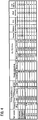
FIG. 4 is a table showing evaluation results of embodiments and comparative embodiments of the half mirror; -
FIG. 5 is a graph showing measuring data of evaluation results ofEmbodiment 1; -
FIG. 6 is a graph showing measuring data of evaluation results of comparative embodiment CE-1; -
FIG. 7 is a graph showing measuring data of evaluation results of comparative embodiment CE-3; and -
FIG. 8a is a schematic cross-sectional view depicting a conventional lighting apparatus using a half mirror, andFIG. 8b is a partial cross-sectional view depicting the half mirror shown inFIG. 8a . - The disclosed subject matter will now be described in detail with reference to
FIG. 1 to FIG. 7 , in which the same, similar, or corresponding elements use the same reference marks.FIG. 1 is a schematic cross-sectional view showing an exemplary embodiment of a half mirror made in accordance with principles of the presently disclosed subject invention. Thehalf mirror 1 can include abase material 3 having afirst surface 3A and asecond surface 3B formed in a substantially planar shape, and ahalf mirror layer 2 having a central line 2LCL, an incident surface 2IN and an outgoing surface 2OG formed in a substantially film shape and disposed on at least one of thefirst surface 3A and thesecond surface 3B of thebase material 3. - The
half mirror 1 can receive Light A from the incident surface 2IN of thehalf mirror layer 2 and can reflect Light B, which is a part of Light A, from the outgoing surface 2OG of thehalf mirror layer 2. Thehalf mirror 1 can emit Light C, which is another part of Light A, from thesecond surface 3B of thebase material 3, when thehalf mirror layer 2 is disposed on thefirst surface 3A of thebase material 3 so that the outgoing surface 2OG thereof faces thefirst surface 3A, as shown inFIG. 1 . Accordingly, as thebase material 3, which may optically transmits Light C, a transparent material such as a polycarbonate resin, an acrylic resin and the like can be used. - The
half mirror layer 2 can include a chrome oxide layer 2CO. With respect to the chrome oxide layer 2CO, a distributional minimum of a ratio of oxide atomic element to chrome atomic element in a thick direction 2LD of thehalf mirror layer 2 toward thebase material 3 can be 0.55 or more, and a distributional maximum of the ratio of oxide atomic element to chrome atomic element in the thick direction 2LD of thehalf mirror layer 2 toward thebase material 3 can be 0.86 or less. Additionally, the ratio of oxide atomic element to chrome atomic element on the central line 2LCL, which extends on a center between the incident surface 2IN and the outgoing surface 2OG of thehalf mirror layer 2, in the thick direction 2LD of thehalf mirror layer 2 can be 0.67 or more. - In the embodiment of the
half mirror layer 2, a distributional minimum of oxide composition of the chrome oxide layer 2CO in the thick direction 2LD of thehalf mirror layer 2 can be 35 atomic percent or more, and a distributional maximum of oxide composition of the chrome oxide layer 2CO in the thick direction 2LD of thehalf mirror layer 2 can be 46 atomic percent or less. - The
half mirror 1, in which the chrome oxide layer 2CO is used as thehalf mirror layer 2 and is disposed on thebase material 3, can perform a high thermal resistance including the thermal resistance against a low temperature, and therefore cannot crack even under various circumstances such that repeat a low temperature and a high temperature. Accordingly, thehalf mirror 1 can maintain a stable reflectivity for a long term, and also can maintain a good appearance for a long-term use because thehalf mirror 1 cannot crack even under tough circumstances described above. - As the
base material 3, a polycarbonate resin, which is a lightweight material and has an excellent formability, can be used, as described above. As thehalf mirror layer 2, thehalf mirror 1 can be made by disposing only the chrome oxide layer 2CO on at least one of thefirst surface 3A and thesecond surface 3B of thebase material 3 without a protection film. Accordingly, thehalf mirror layer 2 can perform a high thermal resistance including the thermal resistance against a low temperature in addition to excellent moisture resistance and chemical resistance to acids and alkalis when a distributional minimum having 0.55 or more of oxide atomic to chrome atomic of the chrome oxide layer 2CO in the thick direction 2LD of thehalf mirror layer 2 is used as the chrome oxide layer 2CO for thehalf mirror layer 2. - A thickness of the chrome oxide layer 2CO can be determined in accordance with a desirable reflectivity and a preferable transmissivity as usage, for example, can be between 10 nanometers and 40 nanometers. An exemplary method for manufacturing the
half mirror 1 of the invention will now be described with reference toFIG. 2a and FIG. 2b , in whichFIG. 2a is a schematic block diagram depicting an exemplary method for manufacturing the half mirror shown inFIG. 1 , andFIG. 2b is a schematic diagram depicting a sputtering equipment used for manufacturing the half mirror. -
Process 1 is preparing thebase material 3 as shown in S21 ofFIG. 2a . -
Process 2 is forming a chrome layer on thebase material 3 by a sputtering method as shown in S22. More specifically, achromium target 24 can arranged in acoating chamber 25 of asputtering equipment 26, and thebase material 3 can be held as a positive electrode by abase holder 27 at a position where thebase material 3 faces thechromium target 24 setting as a negative electrode. Then, an argon gas used as a sputtering gas can fill at a prescribed pressure into thecoating chamber 25 via aninjection valve 28 after being exhausted in thecoating chamber 25 via an exhaust pump 29, and the argon gas is ionized by applying direct current (DC) between the positive electrode connecting thebase material 3 and the negative electrode connecting thechromium target 24, thereby the chromium layer can be formed on thebase material 3 by sputtering thechromium target 24. - While forming the chrome oxide layer 2CO on the
base material 3 by a sputtering method, the prescribed pressure of the argon gas in thecoating chamber 25 of the sputteringequipment 26 can be more than 0.8 Pascal (Pa), and preferably can be more than 1.5 Pa. The DC applied between the positive electrode connecting thebase material 3 and the negative electrode connecting thechromium target 24 can be less than 1,500 watts in a power equivalent including a load described above. -
Process 3 is forming the chrome oxide layer 2CO on thebase material 3 by injecting oxygen (O) or a gas including the oxygen (e.g., air) via theinjection valve 28 and finishing thehalf mirror 1 as shown in S23 ofFIG. 2a . Thehalf mirror 1 including the chrome oxide layer 2CO having the above-described distribution of the ratio of oxide atomic element to chrome atomic element in the thick direction 2LD of thehalf mirror layer 2 and/or the above-described distribution of the oxide atomic to the chrome atomic of the chrome oxide layer 2CO can be manufactured by the exemplary manufacturing method described above. - The
half mirror 1, which is manufactured by the exemplary manufacturing method, can perform a high thermal resistance including the thermal resistance against a low temperature, and therefore cannot crack even under various circumstances such that repeat a low temperature and a high temperature. Evaluating results of thehalf mirror 1 will be described later. - Next, exemplary embodiments of a vehicle lamp using the half mirror will now be described with reference to
FIG. 3a to FIG. 3c , in whichFIG. 3a is a schematic side cross-sectional view showing an exemplary embodiment of a lighting unit using thehalf mirror 1 shown inFIG. 1 , andFIGs. 3b and 3c are partial enlarged cross-sectional views taken along circle 1C shown inFIG. 3a showing an exemplary location and another exemplary location of thehalf mirror 1, respectively. - The
lighting unit 30 can include: acasing 31 having an opening 31OP; thehalf mirror 1 attached to the opening 31OP of thecasing 31; and alight source 32 having anelectric supply line 33 facing thehalf mirror 1 and attached to thecasing 31. Thehalf mirror 1 including thehalf mirror layer 2, which is disposed on thebase material 3, can be located so that thebase material 3 faces thelight source 32 in order for thehalf mirror layer 2 to become a light-emitting surface of thelighting unit 30 shownFIG. 3b . - As the
light source 32, a laser light-emitting apparatus, which can emit various color lights including while color light and which is disclosed in Patent Document No. 3, can be used, and also a surface mount light-emitting device, which can emit various color lights including while color light and which is disclosed in Patent Document No. 4, can be used. Patent Documents No. 3 and No. 4 are owned by Applicant of this disclosed subject matter. Accordingly, detail descriptions of thelight source 32 will be abbreviated here. - When the
light source 32 turns on, various color lights emitted from thelight source 32 can transmit thehalf mirror 1, and therefore can enable thelighting unit 30 to behave various lighting units. When thelight source 32 turns off, thehalf mirror 1 can reflect outward lights such as sunlight, and therefore can enable a middle of thelighting unit 30 to disappear from view. Thus, the disclose subject matter can provide thelighting unit 30 having an excellent appearance. - In addition, the
half mirror 1 can perform a high thermal resistance including the thermal resistance against a low temperature in addition to excellent moisture resistance and chemical resistance to acids and alkalis, and also can maintain a stable reflectivity and a good appearance for a long-term use because thehalf mirror 1 cannot crack even under tough circumstances described above. Accordingly, thelighting unit 31 using thehalf mirror 1 can be used for vehicle lamp such as a headlight, a tail lamp, etc. - When the
lighting unit 30 is used for the vehicle lamp, thelighting unit 30 can be used for the headlight having a light-emitting efficiency by coating a reflective surface such as aluminum layer and the like on an inner surface 31IS of thecasing 31 and by using thelight source 32, which emits substantially white light. When thelighting unit 30 is used for the vehicle lamp, thelighting unit 30 can be used for the tail lamp and/or a stop lamp having a light-emitting efficiency by coating a reflective surface such as aluminum layer and the like on an inner surface 31IS of thecasing 31 and by using thelight source 32, which emits red light. Similarly, when thelighting unit 30 is used for the vehicle lamp, thelighting unit 30 can be used for a turn signal lamp by using thelight source 32, which emits amber light. - When the
half mirror 1 is attached to thecasing 31, thehalf mirror 1 can also be attached to thecasing 31 so that thehalf mirror layer 2 faces thelight source 32 as shown inFIG. 3c . Even when thelighting unit 30 is structured by such a location of thehalf mirror 1, thelighting unit 30 can enjoy the above-described performances such as the high thermal resistance, the chemical resistance and the like in common with the above-described location shown inFIG. 3b . Accordingly, thelight source 32 can also include a laser device having a high emitting-efficiency in common with a light emitting diode, a bulb, etc. - Next, the evaluation results of the
half mirror 1 will now be described with reference toFIG. 4 to FIG. 7 . Embodiments 1-3 for evaluating the performances of thehalf mirror 1 were manufactured as shown inFIG. 4 . A polycarbonate resin as thebase material 3 is located in the coating chamber of the sputtering equipment so as to face the chromium target, which is set at a distance of 165millimeters from the polycarbonate. After the coating chamber was exhausted at a pressure of 2 to 4 × 10⁻³ Pa, the argon gas having a flow of 82.5 seem fills at the pressures of 1.5Pa whenEmbodiment 1 is manufactured, 1.6Pa whenEmbodiment 2 is manufactured and 2.6Pa whenEmbodiment 3 is manufactured. In these cases, the sputtering power is set up at 1,500W and the forming time is between 10 seconds and 20 seconds. - As a result, each of layer thicknesses of
Embodiments 1 to 3 became 26 nanometers, 65 nanometers and 34 nanometers, respectively, as shown inFIG. 4 . After forming the chrome layer on the polycarbonate resin, each of half mirrors ofEmbodiments 1 to 3 was manufactured by filling the air in the coating chamber of the sputtering equipment. Next, comparative embodiments CE-1, CE-2, CE-3, CE-4 and CE-5 were manufactured as follows. - The polycarbonate resin is located in the coating chamber of the sputtering equipment so as to face the chromium target, which is set at the distance of 165 millimeters from the polycarbonate. After the coating chamber was exhausted at a pressure of 2 to 4 × 10⁻³ Pa, the argon gas having a flow of 15 seem fills at the pressures of 0.09 Pa to 1.5 Pa, and the sputtering power is set up at 1,500W to 6,000W and the forming time is between 6 seconds and 8 seconds. As a result, each of layer thicknesses of Comparative Embodiments CE-1 to CE-5 became 25, 15, 30, 25 and 25 nanometers, respectively, as shown in
FIG. 4 . After forming the chrome layer on the polycarbonate resin, each of half mirrors of Comparative Embodiments CE-1 to CE-5 was manufactured by filling the air in the coating chamber of the sputtering equipment. - With respect to the embodiments 1-3 and the comparative embodiments CE-1 to CE-5, each of atomic concentrations of chrome elements, oxygen elements and carbon elements in a depth direction of the
half mirror layers 2 was measured by X-ray photoelectron spectroscopy (XPS). Each of measuring data of theembodiment 1 and the comparative embodiments CE-2 and CE-3 are shown inFIG. 6 to FIG. 7 as representative examples, respectively, in which a horizontal axis is a depth from a top surface of thehalf mirror layers 2 and a vertical axis is the atomic concentration (at%). - The oxygen composition and O/Cr ratio were shown in
FIG. 4 in accordance with each of the measuring data. Thermal resistance tests of the above-described testing samples were carried out under 120 degrees centigrade for 240 hours. Then, the testing samples were watched by a metallograph, and ×-indications are marked in a column of the thermal resistance in accordance with each row of some testing samples, in which a crazing and/or a crack occur and also ○-indication are marked in the column of the thermal resistance in accordance with each row of other testing samples, which maintain a normal state without the crazing and the crack. - Moisture resistance tests of the testing samples were carried out at a temperature of 50 degrees centigrade and at a humidity of 98 % for 40 hours in a constant temperature reservoir, and were left at room temperature for one hour. Then, the testing samples were watched by a visual contact, and ×-indications are marked in a column of the moisture resistance in accordance with each row of some testing samples, in which at least one of a peeling and a white spot occurs and also ○-indication are marked in the column of the moisture resistance in accordance with each row of other testing samples, which maintain a normal state without the peeling and the white spot.
- With respect to an acid resistance test, sulfuric acid (H2SO4) having a normality of 1N of 0.2 mil liters was dropped on each of the testing samples, and each of the testing samples was left for one hour and was left at room temperature for one hour after being washed with water. Then, the testing samples were watched by a visual contact, and ×-indications are marked in a column of the acid resistance in accordance with each row of some testing samples, in which at least a part of the half mirror layer disappears, and also ○-indication are marked in the column of the acid resistance in accordance with each row of other testing samples, which maintain a normal state.
- With respect to an alkali resistance test, each of the testing samples was dipped in a liquid of potassium hydroxide (KoH) having a concentration of 1% for 10 minutes and was watched by a visual contact. The ×-indications are marked in a column of the alkali resistance in accordance with each row of some testing samples, in which at least one of a peeling and a white spot occurs and the ○-indication are marked in the column of the alkali resistance in accordance with each row of other testing samples, which maintain a normal state without the peeling and the white spot.
- With respect to a low thermal resistance test, after the testing samples were left at a temperature of -40 degrees centigrade for 2 hours and were increased to a temperature of 80 degrees centigrade (a humidity of 90 %) for 40 hours in a constant temperature reservoir, and were left at the
temperature 80 degrees centigrade and at the humidity of 90% for 2 hours and were deceased to the temperature of 80 degrees for 2 hours again. The one thermal cycle of 8 hours was repeated 10 times. Then, the testing samples were watched by the metallograph, and the ×-indications are marked in a column of the low thermal resistance in accordance with each row of some testing samples, in which a crazing and/or a crack occur, and also the ○-indication are marked in the column of the low thermal resistance in accordance with each row of other testing samples, which maintain a normal state without the crazing and the crack a visual contact. - According to the evaluation results shown in
FIG. 4 ,Embodiments 1 to 3 can perform the excellent thermal resistance, moisture resistance, acid resistance and low thermal resistance, wherein the O/Cr ration of the embodiments is from 0.55 to 0.86 and the O/Cr ration is 0.67 or more on the central line. Additionally, the oxygen composition in the chromium oxide layer can be 35 at% or more and can be 46 at% or less. - On the other hand, Comparative Embodiments CE-1 to CE-5 may not perform the excellent thermal resistance and low thermal resistance. The O/Cr ration of the comparative embodiments is from 0.13 to 0.63 and the O/Cr ration is 0.39 or less on the central line. Additionally, the oxygen composition in the chromium oxide layer can be 12 at% or more and can be 38 at% or less.
- As described above, in the chrome oxide layers 2CO of Embodiments 1-3, which are manufactured under the pressure of the argon gas having 1.5 Pa or more and the sputtering power having 1,500 watts or less, the distributional minimum of the ratio of the oxide atomic element to the chrome atomic element in the thick direction of the
half mirror layer 2 can be 0.55 or more, and also the distributional minimum of the oxide composition of the chrome oxide layer in the thick direction of the half mirror layer can be 35 atomic at % or more. - Accordingly, the chrome oxide layers 2CO of Embodiments 1-3 become a larger oxygen composition than the comparative embodiments CE-1 to CE-5. Because the O/Cr ratios of Embodiments 1-3 become a larger than these of the comparative embodiments CE-1 to CE-5, each of Embodiments 1-3 can include a larger oxygen compositions even on the central line. Thus, the disclosed subject matter can provide half mirrors having a high durability such as a thermal resistance, which can prevent the half mirrors from cracking even under various tough circumstances such that repeat a low temperature and a high temperature.
- According to the exemplary half mirrors, the exemplary half mirrors can be incorporated into lighting units such as vehicle lamps and lighting apparatuses such as room lights, outdoor luminaires, etc. The lighting units can include a light source, which emits various color lights including white color light. Thus, the disclosed subject matter can also provide the lighting units using the half mirror having a high durability, which can maintain a stable reflectivity for a long term and also can maintain a good appearance for a long-term use because the half mirror can prevent cracking therein even under tough circumstances. Additionally, the disclosed subject matter can provide the methods for manufacturing the half mirrors having a high durability in simple manufacturing processes as described above.
- Various modifications of the above disclosed embodiments can be made without departing from the spirit and scope of the presently disclosed subject matter. For example, cases where the
half mirror 1 is formed in a substantially plane shape are described. However, the half mirrors is not limited to this shape and can be formed in various shapes such as a curved shape, a ring shape, etc. In addition, the specific arrangement between components can vary between different applications, and several of the above-described features can be used interchangeably between various embodiments depending on a particular application of the lighting unit. - While there has been described what are at present considered to be exemplary embodiments of the invention, it will be understood that various modifications may be made thereto, and it is intended that the appended claims cover such modifications as fall within the true spirit and scope of the invention. All conventional art references described above are herein incorporated in their entirety by reference.
Claims (15)
- A half mirror, comprising:a base material having a first surface and a second surface formed in a substantially planar shape and made from a transparent material;a half mirror layer having a central line including chrome oxide and formed on at least one of the first surface and the second surface of the base material as a chrome oxide layer; and characterized in that a distributional minimum of a ratio of oxide atomic element to chrome atomic element in a thick direction of the half mirror layer toward the base material is 0.55 or more.
- The half mirror according to claim 1, wherein a distributional maximum of the ratio of the oxide atomic element to the chrome atomic element in the thick direction of the half mirror layer toward the base material is 0.86 or less.
- The half mirror according to claim 1, wherein a distributional minimum of oxide composition of the chrome oxide layer in the thick direction of the half mirror layer toward the base material is 35 atomic percent (at %) or more.
- The half mirror according to claim 1, wherein a distributional maximum of oxide composition of the chrome oxide layer in the thick direction of the half mirror layer toward the base material is 46 at % or less.
- The half mirror according to claim 1, wherein a ratio of oxide atomic element to chrome atomic element on the central line in the thick direction of the half mirror layer 2 toward the base material is 0.67 or more.
- The half mirror according to claim 2, wherein the base material includes a polycarbonate resin.
- A method for manufacturing the half mirror according to claim 1, comprising:preparing the base material;forming a chrome layer on the base material by a sputtering method, wherein a pressure of argon gas in a coating chamber of a sputtering equipment is more than 1.5 Pa, and a power is less than 1,500 watts when a direct current (DC) is applied between a positive electrode connecting the base material and a negative electrode connecting a chromium target; andforming the chrome oxide layer on the base material 3 by injecting oxygen or a gas including the oxygen in the coating chamber of the sputtering equipment.
- A method for manufacturing the half mirror according to claim 2, comprising:preparing the base material;forming a chrome layer on the base material by a sputtering method, wherein a pressure of argon gas in a coating chamber of a sputtering equipment is more than 1.5 Pa, and a power is less than 1,500 watts when DC is applied between a positive electrode connecting the base material and a negative electrode connecting a chromium target; andforming the chrome oxide layer on the base material by injecting oxygen or a gas including the oxygen in the coating chamber of the sputtering equipment.
- A method for manufacturing the half mirror according to claim 3, comprising:preparing the base material;forming a chrome layer on the base material by a sputtering method, wherein a pressure of argon gas in a coating chamber of a sputtering equipment is more than 1.5 Pa, and a power is less than 1,500 watts when DC is applied between a positive electrode connecting the base material and a negative electrode connecting a chromium target; andforming the chrome oxide layer on the base material by injecting oxygen or a gas including the oxygen in the coating chamber of the sputtering equipment.
- A method for manufacturing the half mirror according to claim 4, comprising:preparing the base material;forming a chrome layer on the base material by a sputtering method, wherein a pressure of argon gas in a coating chamber of a sputtering equipment is more than 1.5 Pa, and a power is less than 1,500 watts when DC is applied between a positive electrode connecting the base material and a negative electrode connecting a chromium target; andforming the chrome oxide layer on the base material by injecting oxygen or a gas including the oxygen in the coating chamber of the sputtering equipment.
- A lighting unit using the half mirror according to claim 1, comprising:a casing having an opening and an inner surface, and the opening of the casing attached to the half mirror; anda light source attached to the casing and facing the half mirror.
- A lighting unit using the half mirror according to claim 2, comprising:a casing having an opening and an inner surface, and the opening of the casing attached to the half mirror; anda light source attached to the casing and facing the half mirror.
- A lighting unit using the half mirror according to claim 3, comprising:a casing having an opening and an inner surface, and the opening of the casing attached to the half mirror; anda light source attached to the casing and facing the half mirror.
- A lighting unit using the half mirror according to claim 4, comprising:a casing having an opening and an inner surface, and the opening of the casing attached to the half mirror; anda light source attached to the casing and facing the half mirror.
- The lighting unit according to claim 11, wherein the inner surface of the casing is a reflective surface.
Applications Claiming Priority (1)
| Application Number | Priority Date | Filing Date | Title |
|---|---|---|---|
| JP2015247400A JP2017111381A (en) | 2015-12-18 | 2015-12-18 | Half mirror, lighting fixture comprising half mirror, and method for producing half mirror |
Publications (1)
| Publication Number | Publication Date |
|---|---|
| EP3182192A1 true EP3182192A1 (en) | 2017-06-21 |
Family
ID=57838123
Family Applications (1)
| Application Number | Title | Priority Date | Filing Date |
|---|---|---|---|
| EP16204283.2A Withdrawn EP3182192A1 (en) | 2015-12-18 | 2016-12-15 | Half mirror, method for manufacturing the same and lighting unit using the same |
Country Status (3)
| Country | Link |
|---|---|
| US (1) | US10429554B2 (en) |
| EP (1) | EP3182192A1 (en) |
| JP (1) | JP2017111381A (en) |
Families Citing this family (2)
| Publication number | Priority date | Publication date | Assignee | Title |
|---|---|---|---|---|
| CN112639354B (en) * | 2018-08-28 | 2023-02-03 | Zkw集团有限责任公司 | Vehicle lamp using semiconductor light emitting device |
| EP4170414B1 (en) * | 2020-06-17 | 2026-01-28 | Arisawa Mfg. Co., Ltd. | Three-dimensional display device |
Citations (8)
| Publication number | Priority date | Publication date | Assignee | Title |
|---|---|---|---|---|
| EP0756131A1 (en) * | 1995-07-28 | 1997-01-29 | MAGNETI MARELLI S.p.A. | Vehicle lighting device |
| US5672243A (en) * | 1995-11-28 | 1997-09-30 | Mosel Vitelic, Inc. | Antireflection coating for highly reflective photolithographic layers comprising chromium oxide or chromium suboxide |
| DE20021657U1 (en) * | 2000-12-20 | 2002-05-02 | Alanod Aluminium Veredlung Gmb | Cover part for a light source |
| JP2003115206A (en) | 2001-10-02 | 2003-04-18 | Koito Mfg Co Ltd | Vehicle lighting |
| JP2007087629A (en) | 2005-09-20 | 2007-04-05 | Harison Toshiba Lighting Corp | Lamp |
| JP2010128440A (en) * | 2008-12-01 | 2010-06-10 | Dainippon Printing Co Ltd | Multi-spectral mask and method of manufacturing color filter |
| US20160027968A1 (en) | 2014-07-25 | 2016-01-28 | Stanley Electric Co., Ltd. | Surface mount light-emitting device |
| US20160268770A1 (en) | 2015-03-09 | 2016-09-15 | Stanley Electric Co., Ltd. | Laser light-emitting apparatus |
Family Cites Families (6)
| Publication number | Priority date | Publication date | Assignee | Title |
|---|---|---|---|---|
| US5481409A (en) * | 1990-02-20 | 1996-01-02 | K. W. Muth Company, Inc. | Mirror assembly |
| JPH09146259A (en) * | 1995-08-29 | 1997-06-06 | Ricoh Opt Ind Co Ltd | Gradation mask and its production and method for generating special surface shape by using gradation mask |
| JP2820386B2 (en) * | 1995-12-15 | 1998-11-05 | 台湾茂▲石▼電子股▲分▼有限公司 | Photolithography method |
| DE10029826C1 (en) * | 2000-06-16 | 2001-08-02 | Agfa Gevaert Ag | Method and device for defect detection and / or correction in digital image processing |
| WO2008051846A1 (en) * | 2006-10-20 | 2008-05-02 | Wintek Electro-Optics Corporation | Mixed chromium oxide-chromium metal sputtering target |
| WO2013129425A1 (en) * | 2012-02-27 | 2013-09-06 | 東レ株式会社 | Transfer donor substrate and device manufacturing method |
-
2015
- 2015-12-18 JP JP2015247400A patent/JP2017111381A/en active Pending
-
2016
- 2016-12-14 US US15/378,481 patent/US10429554B2/en active Active
- 2016-12-15 EP EP16204283.2A patent/EP3182192A1/en not_active Withdrawn
Patent Citations (8)
| Publication number | Priority date | Publication date | Assignee | Title |
|---|---|---|---|---|
| EP0756131A1 (en) * | 1995-07-28 | 1997-01-29 | MAGNETI MARELLI S.p.A. | Vehicle lighting device |
| US5672243A (en) * | 1995-11-28 | 1997-09-30 | Mosel Vitelic, Inc. | Antireflection coating for highly reflective photolithographic layers comprising chromium oxide or chromium suboxide |
| DE20021657U1 (en) * | 2000-12-20 | 2002-05-02 | Alanod Aluminium Veredlung Gmb | Cover part for a light source |
| JP2003115206A (en) | 2001-10-02 | 2003-04-18 | Koito Mfg Co Ltd | Vehicle lighting |
| JP2007087629A (en) | 2005-09-20 | 2007-04-05 | Harison Toshiba Lighting Corp | Lamp |
| JP2010128440A (en) * | 2008-12-01 | 2010-06-10 | Dainippon Printing Co Ltd | Multi-spectral mask and method of manufacturing color filter |
| US20160027968A1 (en) | 2014-07-25 | 2016-01-28 | Stanley Electric Co., Ltd. | Surface mount light-emitting device |
| US20160268770A1 (en) | 2015-03-09 | 2016-09-15 | Stanley Electric Co., Ltd. | Laser light-emitting apparatus |
Also Published As
| Publication number | Publication date |
|---|---|
| US20170176655A1 (en) | 2017-06-22 |
| US10429554B2 (en) | 2019-10-01 |
| JP2017111381A (en) | 2017-06-22 |
Similar Documents
| Publication | Publication Date | Title |
|---|---|---|
| JP6340608B2 (en) | High durability silver mirror | |
| JP5719179B2 (en) | Reflective film laminate | |
| US20090175043A1 (en) | Reflector for lighting system and method for making same | |
| US10429554B2 (en) | Half mirror, method for manufacturing the same and lighting unit using the same | |
| CN101809467A (en) | Reflective film, reflective film laminate, LED, organic EL display, and organic EL lighting device | |
| JPWO2006132414A1 (en) | Silver alloy with excellent reflectivity and transmittance maintenance characteristics | |
| US7829191B2 (en) | Lens for lighting system | |
| JP2012068608A (en) | Reflective film laminate | |
| CN107924976A (en) | Light source | |
| US20090167182A1 (en) | High intensity lamp and lighting system | |
| JP2008541366A (en) | Reflectors for infrared radiating elements | |
| JP5097031B2 (en) | Reflective film, LED, organic EL display, and organic EL lighting fixture | |
| US12259100B1 (en) | Thick appearance lens using reflective surfaces | |
| US20080096010A1 (en) | Rear Surface Mirror | |
| JPWO2006132417A1 (en) | Silver alloy with excellent reflectivity and transmittance maintenance characteristics | |
| WO2006132416A1 (en) | Silver alloy excellent in reflectance/transmittance maintaining characteristics | |
| KR101557443B1 (en) | Lighting device | |
| JP2011249051A (en) | Illumination fixture | |
| CN102754024B (en) | Discharge tube and stroboscopic device | |
| JP2007121461A (en) | Reflective member having heat resistance and lighting apparatus having the same | |
| JP2006302719A (en) | Infrared bulb having a reflective film and method for manufacturing the same | |
| US20090168445A1 (en) | Covert filter for high intensity lighting system | |
| JP2011154815A (en) | Luminaire | |
| CN202749335U (en) | Spiral energy-saving lamp | |
| JP5942283B2 (en) | Reflector for lighting equipment |
Legal Events
| Date | Code | Title | Description |
|---|---|---|---|
| PUAI | Public reference made under article 153(3) epc to a published international application that has entered the european phase |
Free format text: ORIGINAL CODE: 0009012 |
|
| AK | Designated contracting states |
Kind code of ref document: A1 Designated state(s): AL AT BE BG CH CY CZ DE DK EE ES FI FR GB GR HR HU IE IS IT LI LT LU LV MC MK MT NL NO PL PT RO RS SE SI SK SM TR |
|
| AX | Request for extension of the european patent |
Extension state: BA ME |
|
| 17P | Request for examination filed |
Effective date: 20171219 |
|
| RBV | Designated contracting states (corrected) |
Designated state(s): AL AT BE BG CH CY CZ DE DK EE ES FI FR GB GR HR HU IE IS IT LI LT LU LV MC MK MT NL NO PL PT RO RS SE SI SK SM TR |
|
| 17Q | First examination report despatched |
Effective date: 20180430 |
|
| STAA | Information on the status of an ep patent application or granted ep patent |
Free format text: STATUS: THE APPLICATION IS DEEMED TO BE WITHDRAWN |
|
| 18D | Application deemed to be withdrawn |
Effective date: 20200701 |