EP3182114A1 - Partial discharge monitoring of electrical machines using acoustic emission sensors and electrical sensors - Google Patents
Partial discharge monitoring of electrical machines using acoustic emission sensors and electrical sensors Download PDFInfo
- Publication number
- EP3182114A1 EP3182114A1 EP16203940.8A EP16203940A EP3182114A1 EP 3182114 A1 EP3182114 A1 EP 3182114A1 EP 16203940 A EP16203940 A EP 16203940A EP 3182114 A1 EP3182114 A1 EP 3182114A1
- Authority
- EP
- European Patent Office
- Prior art keywords
- acoustic emission
- sensors
- event
- data
- partial discharge
- Prior art date
- Legal status (The legal status is an assumption and is not a legal conclusion. Google has not performed a legal analysis and makes no representation as to the accuracy of the status listed.)
- Granted
Links
Images



Classifications
-
- G—PHYSICS
- G01—MEASURING; TESTING
- G01N—INVESTIGATING OR ANALYSING MATERIALS BY DETERMINING THEIR CHEMICAL OR PHYSICAL PROPERTIES
- G01N29/00—Investigating or analysing materials by the use of ultrasonic, sonic or infrasonic waves; Visualisation of the interior of objects by transmitting ultrasonic or sonic waves through the object
- G01N29/14—Investigating or analysing materials by the use of ultrasonic, sonic or infrasonic waves; Visualisation of the interior of objects by transmitting ultrasonic or sonic waves through the object using acoustic emission techniques
-
- G—PHYSICS
- G01—MEASURING; TESTING
- G01R—MEASURING ELECTRIC VARIABLES; MEASURING MAGNETIC VARIABLES
- G01R31/00—Arrangements for testing electric properties; Arrangements for locating electric faults; Arrangements for electrical testing characterised by what is being tested not provided for elsewhere
- G01R31/34—Testing dynamo-electric machines
- G01R31/343—Testing dynamo-electric machines in operation
-
- G—PHYSICS
- G01—MEASURING; TESTING
- G01N—INVESTIGATING OR ANALYSING MATERIALS BY DETERMINING THEIR CHEMICAL OR PHYSICAL PROPERTIES
- G01N27/00—Investigating or analysing materials by the use of electric, electrochemical, or magnetic means
- G01N27/92—Investigating or analysing materials by the use of electric, electrochemical, or magnetic means by investigating breakdown voltage
-
- G—PHYSICS
- G01—MEASURING; TESTING
- G01N—INVESTIGATING OR ANALYSING MATERIALS BY DETERMINING THEIR CHEMICAL OR PHYSICAL PROPERTIES
- G01N29/00—Investigating or analysing materials by the use of ultrasonic, sonic or infrasonic waves; Visualisation of the interior of objects by transmitting ultrasonic or sonic waves through the object
- G01N29/22—Details, e.g. general constructional or apparatus details
- G01N29/24—Probes
- G01N29/2418—Probes using optoacoustic interaction with the material, e.g. laser radiation, photoacoustics
-
- G—PHYSICS
- G01—MEASURING; TESTING
- G01N—INVESTIGATING OR ANALYSING MATERIALS BY DETERMINING THEIR CHEMICAL OR PHYSICAL PROPERTIES
- G01N29/00—Investigating or analysing materials by the use of ultrasonic, sonic or infrasonic waves; Visualisation of the interior of objects by transmitting ultrasonic or sonic waves through the object
- G01N29/44—Processing the detected response signal, e.g. electronic circuits specially adapted therefor
- G01N29/4445—Classification of defects
-
- G—PHYSICS
- G01—MEASURING; TESTING
- G01N—INVESTIGATING OR ANALYSING MATERIALS BY DETERMINING THEIR CHEMICAL OR PHYSICAL PROPERTIES
- G01N29/00—Investigating or analysing materials by the use of ultrasonic, sonic or infrasonic waves; Visualisation of the interior of objects by transmitting ultrasonic or sonic waves through the object
- G01N29/44—Processing the detected response signal, e.g. electronic circuits specially adapted therefor
- G01N29/4481—Neural networks
-
- G—PHYSICS
- G01—MEASURING; TESTING
- G01R—MEASURING ELECTRIC VARIABLES; MEASURING MAGNETIC VARIABLES
- G01R31/00—Arrangements for testing electric properties; Arrangements for locating electric faults; Arrangements for electrical testing characterised by what is being tested not provided for elsewhere
- G01R31/12—Testing dielectric strength or breakdown voltage ; Testing or monitoring effectiveness or level of insulation, e.g. of a cable or of an apparatus, for example using partial discharge measurements; Electrostatic testing
- G01R31/1209—Testing dielectric strength or breakdown voltage ; Testing or monitoring effectiveness or level of insulation, e.g. of a cable or of an apparatus, for example using partial discharge measurements; Electrostatic testing using acoustic measurements
-
- G—PHYSICS
- G01—MEASURING; TESTING
- G01R—MEASURING ELECTRIC VARIABLES; MEASURING MAGNETIC VARIABLES
- G01R31/00—Arrangements for testing electric properties; Arrangements for locating electric faults; Arrangements for electrical testing characterised by what is being tested not provided for elsewhere
- G01R31/12—Testing dielectric strength or breakdown voltage ; Testing or monitoring effectiveness or level of insulation, e.g. of a cable or of an apparatus, for example using partial discharge measurements; Electrostatic testing
- G01R31/1227—Testing dielectric strength or breakdown voltage ; Testing or monitoring effectiveness or level of insulation, e.g. of a cable or of an apparatus, for example using partial discharge measurements; Electrostatic testing of components, parts or materials
-
- G—PHYSICS
- G06—COMPUTING OR CALCULATING; COUNTING
- G06N—COMPUTING ARRANGEMENTS BASED ON SPECIFIC COMPUTATIONAL MODELS
- G06N20/00—Machine learning
-
- G—PHYSICS
- G06—COMPUTING OR CALCULATING; COUNTING
- G06N—COMPUTING ARRANGEMENTS BASED ON SPECIFIC COMPUTATIONAL MODELS
- G06N5/00—Computing arrangements using knowledge-based models
- G06N5/04—Inference or reasoning models
- G06N5/046—Forward inferencing; Production systems
- G06N5/047—Pattern matching networks; Rete networks
-
- G—PHYSICS
- G01—MEASURING; TESTING
- G01N—INVESTIGATING OR ANALYSING MATERIALS BY DETERMINING THEIR CHEMICAL OR PHYSICAL PROPERTIES
- G01N2291/00—Indexing codes associated with group G01N29/00
- G01N2291/02—Indexing codes associated with the analysed material
- G01N2291/025—Change of phase or condition
- G01N2291/0258—Structural degradation, e.g. fatigue of composites, ageing of oils
-
- G—PHYSICS
- G01—MEASURING; TESTING
- G01N—INVESTIGATING OR ANALYSING MATERIALS BY DETERMINING THEIR CHEMICAL OR PHYSICAL PROPERTIES
- G01N2291/00—Indexing codes associated with group G01N29/00
- G01N2291/02—Indexing codes associated with the analysed material
- G01N2291/028—Material parameters
- G01N2291/0289—Internal structure, e.g. defects, grain size, texture
-
- G—PHYSICS
- G01—MEASURING; TESTING
- G01N—INVESTIGATING OR ANALYSING MATERIALS BY DETERMINING THEIR CHEMICAL OR PHYSICAL PROPERTIES
- G01N2291/00—Indexing codes associated with group G01N29/00
- G01N2291/26—Scanned objects
- G01N2291/263—Surfaces
- G01N2291/2638—Complex surfaces
-
- G—PHYSICS
- G01—MEASURING; TESTING
- G01R—MEASURING ELECTRIC VARIABLES; MEASURING MAGNETIC VARIABLES
- G01R31/00—Arrangements for testing electric properties; Arrangements for locating electric faults; Arrangements for electrical testing characterised by what is being tested not provided for elsewhere
- G01R31/12—Testing dielectric strength or breakdown voltage ; Testing or monitoring effectiveness or level of insulation, e.g. of a cable or of an apparatus, for example using partial discharge measurements; Electrostatic testing
- G01R31/1227—Testing dielectric strength or breakdown voltage ; Testing or monitoring effectiveness or level of insulation, e.g. of a cable or of an apparatus, for example using partial discharge measurements; Electrostatic testing of components, parts or materials
- G01R31/1263—Testing dielectric strength or breakdown voltage ; Testing or monitoring effectiveness or level of insulation, e.g. of a cable or of an apparatus, for example using partial discharge measurements; Electrostatic testing of components, parts or materials of solid or fluid materials, e.g. insulation films, bulk material; of semiconductors or LV electronic components or parts; of cable, line or wire insulation
- G01R31/1272—Testing dielectric strength or breakdown voltage ; Testing or monitoring effectiveness or level of insulation, e.g. of a cable or of an apparatus, for example using partial discharge measurements; Electrostatic testing of components, parts or materials of solid or fluid materials, e.g. insulation films, bulk material; of semiconductors or LV electronic components or parts; of cable, line or wire insulation of cable, line or wire insulation, e.g. using partial discharge measurements
Definitions
- the present invention is directed to systems and methods of detection, characterization, and diagnosis. More specifically, the present invention is directed to systems and methods for the detection and characterization of fatigue cracking and partial discharge events in electrical machines.
- Fatigue cracking and partial discharge (PD) events are both issues for electric generator systems. The phenomena are related in that each may be a contributing factor of the other. Partial discharges tend to increase the number of fatigue cracks, and an increase in the number of fatigue cracks tends to increase the frequency of partial discharges.
- a partial discharge is a localized dielectric breakdown of an electrical insulation system that does not bridge the space between two conductors. A partial discharge generates high frequency transient current pulses that persist for a time period in the range of nanoseconds up to a microsecond. Partial discharges often begin within voids, cracks, such as fatigue cracks, or inclusions, or at conductor-dielectric interfaces within a solid dielectric. A partial discharge may also occur along the boundary between different insulating materials. Although fatigue cracking may result from any type of cyclic stresses on a material, including both mechanical and electrical stresses, the stresses are primarily electrical in the context of electric generator systems. Cumulative partial discharges may cause fatigue cracking events.
- Partial discharges cause progressive deterioration of insulating materials, ultimately leading to an electrical breakdown. Repetitive PD events cause irreversible mechanical and chemical deterioration of the insulating material. Damage is caused by the energy dissipated by high energy electrons or ions, ultraviolet light from the discharges, ozone attacking the void walls, and cracking as the chemical breakdown processes liberate gases at high pressure.
- a history of internal PD in a high-voltage system eventually triggers electrical treeing.
- a history of surface PD eventually induces insulation tracking.
- PD monitoring and detection involves evaluating the dielectric condition of a system by monitoring electrical signals and an analysis of arcing, electric field, materials, wave propagation and attenuation, sensor spatial sensitivity, frequency response and calibration, noise, and data interpretation.
- An electric arc is a visible plasma discharge between two electrodes that is caused by electrical current ionizing gases in the air.
- the magnitude of a partial discharge is related to the extent of damaging discharges occurring and therefore is related to the amount of damage being inflicted on the insulation.
- the pulse repetition rate indicates the quantity of discharges occurring at the various maximum magnitude levels.
- a partial discharge measurement system may include an ultra-high frequency (UHF) sensor, a high frequency current transformer (HFCT), an ultrasonic microphone, a transient earth voltage (TEV) sensor or coupling capacitor, a phase-resolved analysis system to evaluate a wide range of signal frequencies, or combinations thereof.
- UHF ultra-high frequency
- HFCT high frequency current transformer
- TEV transient earth voltage
- a phase-resolved analysis system compares pulse timing to alternating current (AC) frequency.
- a significant problem with electrical detection of partial discharges is that the detection equipment is highly susceptible to electromagnetic noise, which can lead to false detection of partial discharges, typically as false positives.
- the spike caused by a partial discharge may be very small compared to the amplitude of the system voltage and may be missed, leading to a false negative.
- the equipment subjected to testing also needs to be taken off-line, energized from a high-voltage source, and then tested, which requires a lot of time and equipment.
- Conventional PD measurement systems cannot detect fatigue cracks and may detect but do not locate the PD events.
- An acoustic emission is a transient elastic wave within a material, typically the result of a rapid release of localized stress energy, such as when a material undergoes an irreversible change in its structure. Fatigue cracking events generate acoustic emissions.
- Acoustic detection systems detect acoustic emissions as sound waves generally in the frequency range of 20 kHz up to more than 1 MHz. Acoustic detection systems may be external or internal systems. External acoustic detection systems employ sensors mounted to the outside of the equipment to be monitored. Internal systems, on the other hand, use sensors placed inside of the equipment to be monitored to directly measure the pressure wave.
- acoustic detection over other methods is that positioning information is available by using sensors at multiple locations. This position information may help to identify the location of the source of the AE.
- Another advantage of acoustic detection is its immunity to electromagnetic interference or electromagnetic noise.
- a method of monitoring a system includes synchronizing an acoustic emission monitoring system including a plurality of acoustic emission sensors and a partial discharge monitoring system including a plurality of partial discharge sensors, directing collection by the acoustic emission sensors of acoustic emission signals from the component as acoustic emission data and directing collection by the partial discharge sensors of electrical signals as electrical data, and classifying a statistical event as a fatigue cracking event or a partial discharge event by pattern recognition of the acoustic emission data and the electrical data.
- a method of monitoring an electric generator system includes directing collection by a plurality of first sensors on a component of the electric generator system of acoustic emission signals from the component as acoustic emission data, and classifying a first statistical event as a fatigue cracking event by pattern recognition of the acoustic emission data.
- a monitoring system in another embodiment, includes an acoustic emission monitoring system including a plurality of acoustic emission sensors, a partial discharge monitoring system including a plurality of partial discharge sensors and synchronized with the acoustic emission monitoring system, and a computer receiving acoustic emission data from the acoustic emission sensors and electrical data from the partial discharge sensors.
- the computer is configured to classify a first statistical event as a fatigue cracking event by pattern recognition of the acoustic emission data and determine a first location and a first damage condition resulting from the fatigue cracking event, classify a second statistical event as a partial discharge event by pattern recognition of the acoustic emission data or the electrical data, and fuse the acoustic emission data and the electrical data for the second statistical event and determine a second location and a second damage condition resulting from the partial discharge event.
- Embodiments of the present disclosure for example, in comparison to concepts failing to include one or more of the features disclosed herein, provide detection of both partial discharge events and fatigue cracking events, determination of the location of a discharge or fatigue cracking event, a reduced sensitivity to electromagnetic noise, prediction of failure of an electric generator system at an early stage where remediation is still possible, data fusion from a PD event, enhanced measurement and characterization of a PD event, identification of a PD event as an internal, a surface, or a corona PD event, or combinations thereof.
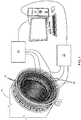
- a monitoring system 10 includes an acoustic emission monitoring system, a partial discharge monitoring system, and a computer 12.
- the monitoring system 10 monitors an electric generator system 14.
- the AE monitoring system includes acoustic emission sensors 16 sensing acoustic emission signals from the electric generator system 14 and an acoustic emission monitoring unit 18 receiving the AE signals from the AE sensors 16 and transmitting acoustic emission data to the computer 12.
- the PD monitoring system includes partial discharge sensors 20 sensing electrical signals from the electric generator system 14 and a partial discharge monitoring unit 22 receiving the electrical signals from the PD sensors 20 and transmitting electrical data to the computer 12. Any type of PD sensor 20 may be used to detect electrical signals within the spirit of the present invention.
- the AE sensors 16 are preferably fiber optic AE sensors. Fiber optic AE sensors without electrically-conductive material are unaffected by the high electrical voltages of the monitored system. Fiber optic AE sensors may be embedded into the insulation material itself without causing any electrical arcing. Furthermore, the fiber optic AC sensors may simultaneously also measure strain and temperature in the system in addition to sensing acoustic emissions.
- the sensors 16, 20 are integrated PD/AE sensors, where each sensor 16, 20 is capable of detecting both electrical signals and AE signals.
- the integrated PD/AE sensors 16, 20 each include a transducer integrating AE sensing and electrical-based PD sensing in one package.
- the monitored electric generator system is a two-pole, three-phase generator system, and the sensors are located on the six outputs (the two poles of each of the three phases) of the monitored electric generator system.
- the electric generator system is a four-pole, three-phase electric generator system, and the sensors are located on the twelve outputs (the four poles of each of the three phases) of the monitored electric generator system.
- the computer 12 receives the acoustic emission data from the acoustic emission monitoring system and the electrical data from the partial discharge monitoring system.
- the computer 12 is configured, either by software, hardware, user input, or a combination thereof, to classify a first statistical event as a fatigue crack by pattern recognition of the acoustic emission data and determine a first location and a first damage condition of the fatigue crack, classify a second statistical event as a partial discharge by pattern recognition of the acoustic emission data or the electrical data, and fuse the acoustic emission data and the electrical data for the second statistical event and determine a second location and a second damage condition of the partial discharge.
- a method of monitoring an electric generator system 14 includes locating acoustic emission sensors 16 of an acoustic emission detection system on a component of the electric generator system 14 and locating partial discharge sensors 20 of a partial discharge detection system on the component.
- the component is a copper/insulator component.
- the sensors 16, 20 are located on the lower lead connection rings, as shown in FIG. 1 .
- the method also includes synchronizing the acoustic emission detection system and the partial discharge detection system (step 32). In some embodiments, a clock 30 synchronizes the two systems (step 32). As the detected events occur on the time scale of microseconds, as precise a synchronization as possible is desirable.
- the method also includes directing collection by the acoustic emission sensors 16 of acoustic emission signals from the component as acoustic emission data and directing collection by the partial discharge sensors 20 of electrical signals from the component as electrical data.
- the acoustic emission detection system records acoustic emission signals as acoustic emission data (step 34) simultaneously with the partial discharge detection system recording electrical signals as electrical data (step 36).
- acoustic features are extracted from the acoustic emission data (step 38), and electrical features are extracted from the electrical data (step 40).
- acoustic pattern recognition classifies the acoustic features as acoustic statistical events (step 42), and electrical pattern recognition classifies the electrical features as electrical statistical events (step 44). Any appropriate pattern recognition process may be implemented within the spirit of the present invention.
- the acoustic statistical events and the electrical statistical events are compared as a cross-check for consistency, clarification, and confirmation of the classifications by the separate systems (step 46).
- Any acoustic emission data corresponding to an acoustic statistical event classified as a fatigue cracking event may be analyzed to determine the location and severity of the fatigue cracking event (step 48).
- Any acoustic emission data corresponding to an acoustic emission event classified as a PD event is analyzed (step 50)
- any electrical data corresponding to an electrical statistical event classified as a PD event is analyzed (step 52)
- the acoustic emission data and the electrical data may be fused to further characterize the PD events (step 54).
- the PD events are characterized as internal, surface, or corona PD events.
- the fatigue cracking event results and the PD event results are then interpreted to estimate a damage condition of the electric generator system (step 56).
- Acoustic emission refers to the phenomenon of generation and propagation of acoustic (elastic) waves in solids that occurs when a material undergoes irreversible changes in its internal structure. For example, crack formation or an external loading, such as a partial discharge, may cause an acoustic emission.
- Feature extraction is preferably based first on defining an amplitude threshold 60 such that the system looks for peaks greater than that amplitude threshold 60.
- the system may look for a cluster of such peaks.
- the duration 62 of the peaks is the time from when the first peak crosses the threshold 60 until the last peak falls below the threshold 60.
- the duration for the event in FIG. 3 is about 34 ⁇ s.
- the rise time 64 is the time from when the first peak crosses the threshold 60 until the largest peak reaches its maximum value.
- the rise time for the event in FIG. 3 is about 16 ⁇ s.
- the peak amplitude 66 is the height of the largest peak, and the counts 68 are for each time a peak goes above the threshold 60. Five such counts 68 are shown in FIG. 3 .
- the method monitors a system in situ in real time.
- a system monitors electric generator components in real time.
- On-line partial discharge testing may allow for trending and analysis of electrical equipment. An examination of the partial discharge activity relative to the 360 degrees of an AC cycle allows for identifying a prominent root cause of partial discharges such that appropriate corrective actions may be implemented. The fact that PD events always occur during the first and third quarters of the AC cycle, as shown in FIG. 7 , helps AE and PD systems to benefit from each other in better classifying PD events and AE events.
- On-line partial discharge testing may detect insulation in the progressive phases of deterioration, with trending being able to identify problems long before an eventual failure.
- the method monitors a system for quality control or inspection purposes during a time at which the system may be off-line or shut down or during production of the system.
- the system measures exaggerated negative polarity pulses under positive charging and measures exaggerated positive polarity pulses under negative charging.
- the system monitors during factory/outage high-potential (hipot) testing and insulation quality control (QC) testing.
- Hipot testing refers to a class of electrical tests to verify the condition of the electrical insulation in an electrical system.
- hipot testing involves applying a high voltage and monitoring the resulting current flowing through the insulation to determine whether the insulation is sufficient to protect from electrical shock.
- insulation quality control acoustic emission data is collected. This data may be used to supplement a hipot test. In some embodiments, the methods are applied in-service during an outage. In some embodiments, quality control acoustic emission data supplements a hipot test. In some embodiments, an AE system and/or a PD system is applied in-service during an outage.
- the PD monitoring of an electric generator system is enhanced using AE data to predict and prevent a potential future failure of the system.
- an AE system records AE signals as AE data, extracts features, and classifies statistical events using a pattern recognition method.
- a PD system collects and records electrical data, extracts features, and classifies statistical events using a pattern recognition method.
- the AE system interprets the AE data to determine the damage condition caused by the fatigue cracking event.
- the AE system and the PD system work together by fusing the AE data and the PD electrical data to interpret the damage condition caused by the PD event. Any appropriate data fusion method may be used within the spirit of the present invention.
- the AE system and PD system together form an integrated system for detecting fatigue cracking events and partial discharge events.
- An AE system and a PD system monitoring in combination offers data fusion from a PD event, which helps the PD system and the AE system benefit from each other and leads to enhanced measurement and characterization of the PD event.
- a rapid decrease in measured PD intensity serves as an indication of an impending failure of the monitored system.
- an AE system monitors one or more components of an electric generator in real time for PD events and fatigue cracking events.
- AE system data enhances a PD measurement system.
- PD system data enhances an AE system.
- feature extraction and pattern recognition from AE and/or PD system data provides PD and fatigue crack-related event classification.
- adaptive machine learning enhances the integrated monitoring system.
- quality control acoustic emission data is collected.
- AE detection is not sensitive to electrical noise, it is more effective at detecting smaller PD events than the PD monitoring system in an electric generator system. Whereas PD monitoring systems tend to only start detecting PD events after significant damage has occurred, an AE monitoring system is capable of detecting PD events and hence monitoring damage at an earlier stage to be able to prevent failure more effectively.
- Signal processing and feature extraction may include extraction of peak amplitude 66, frequency, counts or hits 68 above a threshold 60, duration 62, and rise time 64 from the collected data.
- data fusion and adaptive machine learning enhance PD measurement and characterization based on AE system data and PD system data.
- the ratio of events detected by the AE detection system and events detected by the PD detection system is determined and monitored as a function of time. If the ratio remains fairly constant, it may be assumed that the detected events are PD events. If, however, the ratio is increasing in time, the expectation is that something that is not a PD event is occurring, which may indicate the occurrence of one or more fatigue cracking events.
- the monitoring system may include decision-making protocols for evaluating whether the monitored system or component is in an acceptable condition or in an unacceptable condition or is safe for continued operation or must be shut down for repairs or maintenance.
- the systems and methods may be applied to any electrical systems, including, but not limited to, high power electric generator systems, low power electric generator systems, electrical motors, or transformers.
- An AE monitoring system and a PD monitoring system were tested in combination on a metal bar serving as a model electric generator system.
- the monitoring system included transducers, an amplifier, and an oscilloscope.
- a Tesla coil was used to produce arcing to a predetermined location on the metal bar to simulate a PD event.
- ASTM E976 Standard Guide for Determining the Reproducibility of Acoustic Emission Sensor Response
- the 2H, 0.5-mm diameter pencil lead extended about 3 mm through a guide ring prior to the lead break.
- Sensors were located on both sides of the predetermined location on the metal bar and collected AE monitoring system data and PD monitoring system data.
- the AE monitoring system was able to detect signals from both the AE event and the PD event, whereas the PD monitoring system was only able to detect signals from the PD event. Since the PD and fatigue cracking events occurred between the AE sensors, it was possible to calculate the location of the events based on the timing ("time of flight") of the signals reaching the AE sensors. Some of the resulting AE data from these tests is shown in FIG. 4 and FIG. 5.
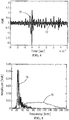
- FIG. 4 and FIG. 5 are based on the same AE sensor data, with the voltage as a function of time in FIG. 4 and as a function of frequency in FIG. 5 .
- the AE data 70 from the crack event showed several strong peaks in the low frequency range of about 20 to about 30 kHz.
- the AE data 72 from the PD event showed a broad weak peak in the higher frequency range of about 60 to about 120 kHz.
- Sample data from a PD monitoring system and an AE monitoring system, synchronized and monitoring the same sample, show how data fusion allows an AE monitoring system to benefit from a PD monitoring system, and vice versa.
- a plot of electrical signals 80 measured by the partial discharge sensors is shown in FIG. 6 as a function of AC phase 82.
- An artificial plot of expected acoustic emissions signals from the same sample as measured by the AE sensors and synchronized with the electrical signals is shown in FIG. 7 .
- the crack event data 84 from the AE sensors is corroborated by the absence of any associated signals from the PD sensors, and the PD event data from the PD sensors is corroborated and enhanced by the associated AE signals 86 from the AE sensors.
Landscapes
- Physics & Mathematics (AREA)
- General Physics & Mathematics (AREA)
- Engineering & Computer Science (AREA)
- Chemical & Material Sciences (AREA)
- Analytical Chemistry (AREA)
- Life Sciences & Earth Sciences (AREA)
- Biochemistry (AREA)
- General Health & Medical Sciences (AREA)
- Immunology (AREA)
- Pathology (AREA)
- Health & Medical Sciences (AREA)
- Theoretical Computer Science (AREA)
- Software Systems (AREA)
- Artificial Intelligence (AREA)
- Evolutionary Computation (AREA)
- Signal Processing (AREA)
- Computing Systems (AREA)
- Mathematical Physics (AREA)
- Computer Vision & Pattern Recognition (AREA)
- General Engineering & Computer Science (AREA)
- Data Mining & Analysis (AREA)
- Acoustics & Sound (AREA)
- Medical Informatics (AREA)
- Electrochemistry (AREA)
- Optics & Photonics (AREA)
- Chemical Kinetics & Catalysis (AREA)
- Computational Linguistics (AREA)
- Testing Relating To Insulation (AREA)
- Investigating Or Analyzing Materials By The Use Of Ultrasonic Waves (AREA)
- Testing Of Devices, Machine Parts, Or Other Structures Thereof (AREA)
- Tests Of Circuit Breakers, Generators, And Electric Motors (AREA)
Abstract
Description
- The present invention is directed to systems and methods of detection, characterization, and diagnosis. More specifically, the present invention is directed to systems and methods for the detection and characterization of fatigue cracking and partial discharge events in electrical machines.
- Fatigue cracking and partial discharge (PD) events are both issues for electric generator systems. The phenomena are related in that each may be a contributing factor of the other. Partial discharges tend to increase the number of fatigue cracks, and an increase in the number of fatigue cracks tends to increase the frequency of partial discharges. A partial discharge is a localized dielectric breakdown of an electrical insulation system that does not bridge the space between two conductors. A partial discharge generates high frequency transient current pulses that persist for a time period in the range of nanoseconds up to a microsecond. Partial discharges often begin within voids, cracks, such as fatigue cracks, or inclusions, or at conductor-dielectric interfaces within a solid dielectric. A partial discharge may also occur along the boundary between different insulating materials. Although fatigue cracking may result from any type of cyclic stresses on a material, including both mechanical and electrical stresses, the stresses are primarily electrical in the context of electric generator systems. Cumulative partial discharges may cause fatigue cracking events.
- Partial discharges cause progressive deterioration of insulating materials, ultimately leading to an electrical breakdown. Repetitive PD events cause irreversible mechanical and chemical deterioration of the insulating material. Damage is caused by the energy dissipated by high energy electrons or ions, ultraviolet light from the discharges, ozone attacking the void walls, and cracking as the chemical breakdown processes liberate gases at high pressure. There are three main types of partial discharges: internal partial discharges, surface partial discharges, and corona partial discharges. A history of internal PD in a high-voltage system eventually triggers electrical treeing. A history of surface PD eventually induces insulation tracking. A history of corona PD originating in the high-voltage connections, however, is generally not harmful.
- PD monitoring and detection involves evaluating the dielectric condition of a system by monitoring electrical signals and an analysis of arcing, electric field, materials, wave propagation and attenuation, sensor spatial sensitivity, frequency response and calibration, noise, and data interpretation. An electric arc is a visible plasma discharge between two electrodes that is caused by electrical current ionizing gases in the air.
- The magnitude of a partial discharge is related to the extent of damaging discharges occurring and therefore is related to the amount of damage being inflicted on the insulation. The pulse repetition rate indicates the quantity of discharges occurring at the various maximum magnitude levels.
- A partial discharge measurement system may include an ultra-high frequency (UHF) sensor, a high frequency current transformer (HFCT), an ultrasonic microphone, a transient earth voltage (TEV) sensor or coupling capacitor, a phase-resolved analysis system to evaluate a wide range of signal frequencies, or combinations thereof. A UHF sensor generally detects in the range of 300 MHz-1.5GHz. An HFCT generally detects in the range of 500 kHz-50 MHz. An ultrasonic microphone generally detects in a range around 40 kHz. A TEV sensor or coupling capacitor generally detects in the range of 3 MHz-100 MHz. A phase-resolved analysis system compares pulse timing to alternating current (AC) frequency.
- A significant problem with electrical detection of partial discharges is that the detection equipment is highly susceptible to electromagnetic noise, which can lead to false detection of partial discharges, typically as false positives. In high voltage systems, however, the spike caused by a partial discharge may be very small compared to the amplitude of the system voltage and may be missed, leading to a false negative. Usually the equipment subjected to testing also needs to be taken off-line, energized from a high-voltage source, and then tested, which requires a lot of time and equipment. Conventional PD measurement systems cannot detect fatigue cracks and may detect but do not locate the PD events.
- An acoustic emission (AE) is a transient elastic wave within a material, typically the result of a rapid release of localized stress energy, such as when a material undergoes an irreversible change in its structure. Fatigue cracking events generate acoustic emissions.
- Acoustic detection systems detect acoustic emissions as sound waves generally in the frequency range of 20 kHz up to more than 1 MHz. Acoustic detection systems may be external or internal systems. External acoustic detection systems employ sensors mounted to the outside of the equipment to be monitored. Internal systems, on the other hand, use sensors placed inside of the equipment to be monitored to directly measure the pressure wave.
- An important advantage of acoustic detection over other methods is that positioning information is available by using sensors at multiple locations. This position information may help to identify the location of the source of the AE. Another advantage of acoustic detection is its immunity to electromagnetic interference or electromagnetic noise.
- In an embodiment, a method of monitoring a system includes synchronizing an acoustic emission monitoring system including a plurality of acoustic emission sensors and a partial discharge monitoring system including a plurality of partial discharge sensors, directing collection by the acoustic emission sensors of acoustic emission signals from the component as acoustic emission data and directing collection by the partial discharge sensors of electrical signals as electrical data, and classifying a statistical event as a fatigue cracking event or a partial discharge event by pattern recognition of the acoustic emission data and the electrical data.
- In another embodiment, a method of monitoring an electric generator system includes directing collection by a plurality of first sensors on a component of the electric generator system of acoustic emission signals from the component as acoustic emission data, and classifying a first statistical event as a fatigue cracking event by pattern recognition of the acoustic emission data.
- In another embodiment, a monitoring system includes an acoustic emission monitoring system including a plurality of acoustic emission sensors, a partial discharge monitoring system including a plurality of partial discharge sensors and synchronized with the acoustic emission monitoring system, and a computer receiving acoustic emission data from the acoustic emission sensors and electrical data from the partial discharge sensors. The computer is configured to classify a first statistical event as a fatigue cracking event by pattern recognition of the acoustic emission data and determine a first location and a first damage condition resulting from the fatigue cracking event, classify a second statistical event as a partial discharge event by pattern recognition of the acoustic emission data or the electrical data, and fuse the acoustic emission data and the electrical data for the second statistical event and determine a second location and a second damage condition resulting from the partial discharge event.
- Other features and advantages of the present invention will be apparent from the following more detailed description, taken in conjunction with the accompanying drawings which illustrate, by way of example, the principles of the invention.
-
-
FIG. 1 is a schematic view of a monitoring system in an embodiment of the present disclosure. -
FIG. 2 is a flow chart of a method of monitoring in an embodiment of the present disclosure. -
FIG. 3 is a plot of an acoustic emission signal in an embodiment of the present disclosure. -
FIG. 4 is a plot of acoustic emission signals for a fatigue cracking event and a partial discharge event in an embodiment of the present disclosure. -
FIG. 5 is a frequency spectrum plot of the acoustic emission signals ofFIG. 4 . -
FIG. 6 is a plot of electrical signals measured by partial discharge sensors in an embodiment of the present disclosure. -
FIG. 7 is a plot of acoustic emission signals measured by acoustic emission sensors and synchronized with the electrical signals ofFIG. 6 . - Wherever possible, the same reference numbers will be used throughout the drawings to represent the same parts.
- Provided are systems and methods for monitoring electric generator systems and detecting and identifying partial discharge events and fatigue cracking events.
- Embodiments of the present disclosure, for example, in comparison to concepts failing to include one or more of the features disclosed herein, provide detection of both partial discharge events and fatigue cracking events, determination of the location of a discharge or fatigue cracking event, a reduced sensitivity to electromagnetic noise, prediction of failure of an electric generator system at an early stage where remediation is still possible, data fusion from a PD event, enhanced measurement and characterization of a PD event, identification of a PD event as an internal, a surface, or a corona PD event, or combinations thereof.
- Referring to
FIG. 1 , a monitoring system 10 includes an acoustic emission monitoring system, a partial discharge monitoring system, and acomputer 12. The monitoring system 10 monitors anelectric generator system 14. The AE monitoring system includesacoustic emission sensors 16 sensing acoustic emission signals from theelectric generator system 14 and an acousticemission monitoring unit 18 receiving the AE signals from theAE sensors 16 and transmitting acoustic emission data to thecomputer 12. The PD monitoring system includespartial discharge sensors 20 sensing electrical signals from theelectric generator system 14 and a partialdischarge monitoring unit 22 receiving the electrical signals from thePD sensors 20 and transmitting electrical data to thecomputer 12. Any type ofPD sensor 20 may be used to detect electrical signals within the spirit of the present invention. - Although piezoelectric AE sensors may be used, the
AE sensors 16 are preferably fiber optic AE sensors. Fiber optic AE sensors without electrically-conductive material are unaffected by the high electrical voltages of the monitored system. Fiber optic AE sensors may be embedded into the insulation material itself without causing any electrical arcing. Furthermore, the fiber optic AC sensors may simultaneously also measure strain and temperature in the system in addition to sensing acoustic emissions. - In some embodiments, the
sensors sensor AE sensors - In some embodiments, the monitored electric generator system is a two-pole, three-phase generator system, and the sensors are located on the six outputs (the two poles of each of the three phases) of the monitored electric generator system. In other embodiments, the electric generator system is a four-pole, three-phase electric generator system, and the sensors are located on the twelve outputs (the four poles of each of the three phases) of the monitored electric generator system.
- The
computer 12 receives the acoustic emission data from the acoustic emission monitoring system and the electrical data from the partial discharge monitoring system. Thecomputer 12 is configured, either by software, hardware, user input, or a combination thereof, to classify a first statistical event as a fatigue crack by pattern recognition of the acoustic emission data and determine a first location and a first damage condition of the fatigue crack, classify a second statistical event as a partial discharge by pattern recognition of the acoustic emission data or the electrical data, and fuse the acoustic emission data and the electrical data for the second statistical event and determine a second location and a second damage condition of the partial discharge. - Referring to
FIG. 1 andFIG. 2 , a method of monitoring anelectric generator system 14 includes locatingacoustic emission sensors 16 of an acoustic emission detection system on a component of theelectric generator system 14 and locatingpartial discharge sensors 20 of a partial discharge detection system on the component. In some embodiments, the component is a copper/insulator component. In some embodiments, thesensors FIG. 1 . The method also includes synchronizing the acoustic emission detection system and the partial discharge detection system (step 32). In some embodiments, aclock 30 synchronizes the two systems (step 32). As the detected events occur on the time scale of microseconds, as precise a synchronization as possible is desirable. The method also includes directing collection by theacoustic emission sensors 16 of acoustic emission signals from the component as acoustic emission data and directing collection by thepartial discharge sensors 20 of electrical signals from the component as electrical data. - The acoustic emission detection system records acoustic emission signals as acoustic emission data (step 34) simultaneously with the partial discharge detection system recording electrical signals as electrical data (step 36). In parallel, acoustic features are extracted from the acoustic emission data (step 38), and electrical features are extracted from the electrical data (step 40). In parallel, acoustic pattern recognition classifies the acoustic features as acoustic statistical events (step 42), and electrical pattern recognition classifies the electrical features as electrical statistical events (step 44). Any appropriate pattern recognition process may be implemented within the spirit of the present invention. The acoustic statistical events and the electrical statistical events are compared as a cross-check for consistency, clarification, and confirmation of the classifications by the separate systems (step 46). Any acoustic emission data corresponding to an acoustic statistical event classified as a fatigue cracking event may be analyzed to determine the location and severity of the fatigue cracking event (step 48). Any acoustic emission data corresponding to an acoustic emission event classified as a PD event is analyzed (step 50), any electrical data corresponding to an electrical statistical event classified as a PD event is analyzed (step 52), and the acoustic emission data and the electrical data may be fused to further characterize the PD events (step 54). In some embodiments, the PD events are characterized as internal, surface, or corona PD events. The fatigue cracking event results and the PD event results are then interpreted to estimate a damage condition of the electric generator system (step 56).
- Acoustic emission, as used herein, refers to the phenomenon of generation and propagation of acoustic (elastic) waves in solids that occurs when a material undergoes irreversible changes in its internal structure. For example, crack formation or an external loading, such as a partial discharge, may cause an acoustic emission.
- Some of the features that may be extracted from AE data are shown in
FIG. 3 . Feature extraction is preferably based first on defining anamplitude threshold 60 such that the system looks for peaks greater than thatamplitude threshold 60. When looking for an event, the system may look for a cluster of such peaks. Theduration 62 of the peaks is the time from when the first peak crosses thethreshold 60 until the last peak falls below thethreshold 60. The duration for the event inFIG. 3 is about 34 µs. Therise time 64 is the time from when the first peak crosses thethreshold 60 until the largest peak reaches its maximum value. The rise time for the event inFIG. 3 is about 16 µs. Thepeak amplitude 66 is the height of the largest peak, and thecounts 68 are for each time a peak goes above thethreshold 60. Fivesuch counts 68 are shown inFIG. 3 . - In some embodiments, the method monitors a system in situ in real time. In some embodiments, a system monitors electric generator components in real time. On-line partial discharge testing may allow for trending and analysis of electrical equipment. An examination of the partial discharge activity relative to the 360 degrees of an AC cycle allows for identifying a prominent root cause of partial discharges such that appropriate corrective actions may be implemented. The fact that PD events always occur during the first and third quarters of the AC cycle, as shown in
FIG. 7 , helps AE and PD systems to benefit from each other in better classifying PD events and AE events. On-line partial discharge testing may detect insulation in the progressive phases of deterioration, with trending being able to identify problems long before an eventual failure. - In other embodiments, the method monitors a system for quality control or inspection purposes during a time at which the system may be off-line or shut down or during production of the system. In some embodiments, the system measures exaggerated negative polarity pulses under positive charging and measures exaggerated positive polarity pulses under negative charging. In some embodiments, the system monitors during factory/outage high-potential (hipot) testing and insulation quality control (QC) testing. Hipot testing, as used herein, refers to a class of electrical tests to verify the condition of the electrical insulation in an electrical system. In some embodiments, hipot testing involves applying a high voltage and monitoring the resulting current flowing through the insulation to determine whether the insulation is sufficient to protect from electrical shock. In some embodiments, insulation quality control acoustic emission data is collected. This data may be used to supplement a hipot test. In some embodiments, the methods are applied in-service during an outage. In some embodiments, quality control acoustic emission data supplements a hipot test. In some embodiments, an AE system and/or a PD system is applied in-service during an outage.
- In some embodiments, the PD monitoring of an electric generator system is enhanced using AE data to predict and prevent a potential future failure of the system. In some embodiments, an AE system records AE signals as AE data, extracts features, and classifies statistical events using a pattern recognition method. In some embodiments, a PD system collects and records electrical data, extracts features, and classifies statistical events using a pattern recognition method. In the case of a fatigue cracking event, the AE system interprets the AE data to determine the damage condition caused by the fatigue cracking event. In the case of a PD event, the AE system and the PD system work together by fusing the AE data and the PD electrical data to interpret the damage condition caused by the PD event. Any appropriate data fusion method may be used within the spirit of the present invention.
- In some embodiments, the AE system and PD system together form an integrated system for detecting fatigue cracking events and partial discharge events. An AE system and a PD system monitoring in combination offers data fusion from a PD event, which helps the PD system and the AE system benefit from each other and leads to enhanced measurement and characterization of the PD event. In some embodiments, a rapid decrease in measured PD intensity serves as an indication of an impending failure of the monitored system.
- In some embodiments, an AE system monitors one or more components of an electric generator in real time for PD events and fatigue cracking events. In some embodiments, AE system data enhances a PD measurement system. In some embodiments, PD system data enhances an AE system. In some embodiments, feature extraction and pattern recognition from AE and/or PD system data provides PD and fatigue crack-related event classification. In some embodiments, adaptive machine learning enhances the integrated monitoring system. In some embodiments, quality control acoustic emission data is collected.
- Since AE detection is not sensitive to electrical noise, it is more effective at detecting smaller PD events than the PD monitoring system in an electric generator system. Whereas PD monitoring systems tend to only start detecting PD events after significant damage has occurred, an AE monitoring system is capable of detecting PD events and hence monitoring damage at an earlier stage to be able to prevent failure more effectively.
- Signal processing and feature extraction may include extraction of
peak amplitude 66, frequency, counts or hits 68 above athreshold 60,duration 62, and risetime 64 from the collected data. In some embodiments, data fusion and adaptive machine learning enhance PD measurement and characterization based on AE system data and PD system data. - In some embodiments, the ratio of events detected by the AE detection system and events detected by the PD detection system is determined and monitored as a function of time. If the ratio remains fairly constant, it may be assumed that the detected events are PD events. If, however, the ratio is increasing in time, the expectation is that something that is not a PD event is occurring, which may indicate the occurrence of one or more fatigue cracking events.
- In some embodiments, regardless of whether the monitoring system monitors in real time or under inspection conditions, the monitoring system may include decision-making protocols for evaluating whether the monitored system or component is in an acceptable condition or in an unacceptable condition or is safe for continued operation or must be shut down for repairs or maintenance.
- The systems and methods may be applied to any electrical systems, including, but not limited to, high power electric generator systems, low power electric generator systems, electrical motors, or transformers.
- An AE monitoring system and a PD monitoring system were tested in combination on a metal bar serving as a model electric generator system. The monitoring system included transducers, an amplifier, and an oscilloscope. A Tesla coil was used to produce arcing to a predetermined location on the metal bar to simulate a PD event. ASTM E976 ("Standard Guide for Determining the Reproducibility of Acoustic Emission Sensor Response") was followed to break a pencil lead against the predetermined location on the metal bar to simulate a fatigue cracking event. The 2H, 0.5-mm diameter pencil lead extended about 3 mm through a guide ring prior to the lead break. Sensors were located on both sides of the predetermined location on the metal bar and collected AE monitoring system data and PD monitoring system data.
- The AE monitoring system was able to detect signals from both the AE event and the PD event, whereas the PD monitoring system was only able to detect signals from the PD event. Since the PD and fatigue cracking events occurred between the AE sensors, it was possible to calculate the location of the events based on the timing ("time of flight") of the signals reaching the AE sensors. Some of the resulting AE data from these tests is shown in
FIG. 4 and FIG. 5. FIG. 4 and FIG. 5 are based on the same AE sensor data, with the voltage as a function of time inFIG. 4 and as a function of frequency inFIG. 5 . TheAE data 70 from the crack event showed several strong peaks in the low frequency range of about 20 to about 30 kHz. TheAE data 72 from the PD event showed a broad weak peak in the higher frequency range of about 60 to about 120 kHz. - Sample data from a PD monitoring system and an AE monitoring system, synchronized and monitoring the same sample, show how data fusion allows an AE monitoring system to benefit from a PD monitoring system, and vice versa. A plot of
electrical signals 80 measured by the partial discharge sensors is shown inFIG. 6 as a function ofAC phase 82. An artificial plot of expected acoustic emissions signals from the same sample as measured by the AE sensors and synchronized with the electrical signals is shown inFIG. 7 . Thecrack event data 84 from the AE sensors is corroborated by the absence of any associated signals from the PD sensors, and the PD event data from the PD sensors is corroborated and enhanced by the associated AE signals 86 from the AE sensors. - While the invention has been described with reference to one or more embodiments, it will be understood by those skilled in the art that various changes may be made and equivalents may be substituted for elements thereof without departing from the scope of the invention. In addition, many modifications may be made to adapt a particular situation or material to the teachings of the invention without departing from the essential scope thereof. Therefore, it is intended that the invention not be limited to the particular embodiment disclosed as the best mode contemplated for carrying out this invention, but that the invention will include all embodiments falling within the scope of the appended claims. In addition, all numerical values identified in the detailed description shall be interpreted as though the precise and approximate values are both expressly identified.
- Various aspects and embodiments of the present invention are defined by the following clauses:
- 1. A method of monitoring a system comprising:
- synchronizing an acoustic emission monitoring system comprising a plurality of acoustic emission sensors with a partial discharge monitoring system comprising a plurality of partial discharge sensors;
- directing collection by the acoustic emission sensors of acoustic emission signals from the component as acoustic emission data and directing collection by the partial discharge sensors of electrical signals as electrical data; and
- classifying a statistical event as a fatigue cracking event or a partial discharge event by pattern recognition of the acoustic emission data and the electrical data.
- 2. The method of
clause 1, wherein the statistical event comprises the partial discharge event, the method further comprising fusing the acoustic emission data and the electrical current data for the statistical event and determining a location and a damage condition resulting from the partial discharge event. - 3. The method of
clause 1, wherein the statistical event comprises the fatigue cracking event, the method comprising classifying the statistical event as the fatigue cracking event by pattern recognition of the acoustic emission data. - 4. The method of
clause 3 further comprising determining a location and a damage condition of the fatigue cracking event from the acoustic emission data. - 5. The method of
clause 1 wherein the system comprises an electric generator system. - 6. The method of
clause 1 wherein the pattern recognition occurs in real time. - 7. The method of clause 6 further comprising implementing adaptive machine learning to enhance the pattern recognition.
- 8. The method of
clause 1 wherein the acoustic emission sensors comprise fiber optic acoustic emission sensors. - 9. A method of monitoring an electric generator system comprising:
- directing collection by a plurality of first sensors on a component of the electric generator system of acoustic emission signals from the component as acoustic emission data; and
- classifying a first statistical event as a fatigue cracking event by pattern recognition of the acoustic emission data.
- 10. The method of clause 9 further comprising determining a location and a damage condition resulting from the fatigue cracking event.
- 11. The method of clause 9 wherein the first sensors comprise fiber optic acoustic emission sensors.
- 12. The method of clause 9 further comprising:
- synchronizing the first sensors with a plurality of second sensors;
- directing collection by the second sensors of electrical signals as electrical data; and
- confirming the fatigue cracking event by pattern recognition of the electrical data.
- 13. The method of clause 9 further comprising directing collection by the first sensors of electrical signals from the component as electrical data.
- 14. The method of clause 13 further comprising classifying a second statistical event as a fatigue cracking event or a partial discharge event by pattern recognition of the acoustic emission data and the electrical data.
- 15. A monitoring system comprising:
- an acoustic emission monitoring system comprising a plurality of acoustic emission sensors;
- a partial discharge monitoring system comprising a plurality of partial discharge sensors and synchronized with the acoustic emission monitoring system; and
- a computer receiving acoustic emission data from the acoustic emission sensors and electrical data from the partial discharge sensors, wherein the computer is configured to:
- classify a first statistical event as a fatigue cracking event by pattern recognition of the acoustic emission data and determine a first location and a first damage condition resulting from the fatigue cracking event;
- classify a second statistical event as a partial discharge event by pattern recognition of the acoustic emission data or the electrical data; and
- 16. The monitoring system of clause 15 wherein the acoustic emission sensors collect the acoustic emission data from acoustic emission signals and the partial discharge sensors collect the electrical data from electrical signals from a component of an electric generator system.
- 17. The monitoring system of clause 15 wherein the computer receives acoustic emission data from the acoustic emission sensors and electrical data from the partial discharge sensors in real time.
- 18. The monitoring system of clause 15 wherein the partial discharge sensors are selected from the group consisting of ultra-high frequency sensors, high frequency current transformers, transient earth voltage sensors, coupling capacitors, and combinations thereof.
- 19. The monitoring system of clause 15 wherein the acoustic emission sensors comprise fiber optic acoustic emission sensors.
- 20. The monitoring system of clause 15 wherein the computer is configured to conduct the pattern recognition in real time.
Claims (10)
- A method of monitoring a system comprising:synchronizing an acoustic emission monitoring system (18) comprising a plurality of acoustic emission sensors (16) with a partial discharge monitoring system (22) comprising a plurality of partial discharge sensors (20);directing collection by the acoustic emission sensors (16) of acoustic emission signals from the component as acoustic emission data and directing collection by the partial discharge sensors (20) of electrical signals (80) as electrical data; andclassifying a statistical event as a fatigue cracking event or a partial discharge event by pattern recognition of the acoustic emission data and the electrical data.
- The method of claim 1, wherein the statistical event comprises the partial discharge event, the method further comprising fusing the acoustic emission data and the electrical current data for the statistical event and determining a location and a damage condition resulting from the partial discharge event.
- The method of claim 1, wherein the statistical event comprises the fatigue cracking event, the method comprising classifying the statistical event as the fatigue cracking event by pattern recognition of the acoustic emission data.
- The method of claim 1 further comprising implementing adaptive machine learning to enhance the pattern recognition.
- The method of claim 1 wherein the acoustic emission sensors (16) comprise fiber optic acoustic emission sensors (16).
- A method of monitoring an electric generator system (14) comprising:directing collection by a plurality of first sensors on a component of the electric generator system (14) of acoustic emission signals from the component as acoustic emission data; andclassifying a first statistical event as a fatigue cracking event by pattern recognition of the acoustic emission data.
- The method of claim 6 further comprising:synchronizing the first sensors with a plurality of second sensors;directing collection by the second sensors of electrical signals (80) as electrical data; andconfirming the fatigue cracking event by pattern recognition of the electrical data.
- The method of claim 6 further comprising directing collection by the first sensors of electrical signals (80) from the component as electrical data.
- A monitoring system (10) comprising:an acoustic emission monitoring system (18) comprising a plurality of acoustic emission sensors (16);a partial discharge monitoring system (22) comprising a plurality of partial discharge sensors (20) and synchronized with the acoustic emission monitoring system (18); anda computer (12) receiving acoustic emission data from the acoustic emission sensors (16) and electrical data from the partial discharge sensors (20), wherein the computer (12) is configured to:classify a first statistical event as a fatigue cracking event by pattern recognition of the acoustic emission data and determine a first location and a first damage condition resulting from the fatigue cracking event;classify a second statistical event as a partial discharge event by pattern recognition of the acoustic emission data or the electrical data; andfuse the acoustic emission data and the electrical data for the second statistical event and determine a second location and a second damage condition resulting from the partial discharge event.
- The monitoring system (10) of claim 9 wherein the acoustic emission sensors (16) comprise fiber optic acoustic emission sensors (16).
Applications Claiming Priority (1)
| Application Number | Priority Date | Filing Date | Title |
|---|---|---|---|
| US14/969,893 US9976989B2 (en) | 2015-12-15 | 2015-12-15 | Monitoring systems and methods for electrical machines |
Publications (2)
| Publication Number | Publication Date |
|---|---|
| EP3182114A1 true EP3182114A1 (en) | 2017-06-21 |
| EP3182114B1 EP3182114B1 (en) | 2020-05-27 |
Family
ID=57749666
Family Applications (1)
| Application Number | Title | Priority Date | Filing Date |
|---|---|---|---|
| EP16203940.8A Active EP3182114B1 (en) | 2015-12-15 | 2016-12-14 | Partial discharge monitoring of electrical machines using acoustic emission sensors and electrical sensors |
Country Status (4)
| Country | Link |
|---|---|
| US (1) | US9976989B2 (en) |
| EP (1) | EP3182114B1 (en) |
| JP (1) | JP6835554B2 (en) |
| CN (1) | CN107024654B (en) |
Cited By (2)
| Publication number | Priority date | Publication date | Assignee | Title |
|---|---|---|---|---|
| CN110376522A (en) * | 2019-09-03 | 2019-10-25 | 宁夏西北骏马电机制造股份有限公司 | A kind of Method of Motor Fault Diagnosis of the deep learning network of data fusion |
| WO2019215158A1 (en) * | 2018-05-07 | 2019-11-14 | Senvion Gmbh | Condition monitoring method and system for electrical power components, in particular transformers |
Families Citing this family (29)
| Publication number | Priority date | Publication date | Assignee | Title |
|---|---|---|---|---|
| US10928436B2 (en) * | 2017-01-30 | 2021-02-23 | General Electric Company | Evaluation of phase-resolved partial discharge |
| CN109073704A (en) | 2017-03-02 | 2018-12-21 | 罗斯蒙特公司 | Trend function for shelf depreciation |
| US10440472B2 (en) | 2017-08-11 | 2019-10-08 | Hubbell Incorporated | Corona detection using audio data |
| CN109142989B (en) * | 2018-06-14 | 2021-07-13 | 中国电力科学研究院有限公司 | Safety assessment method for live operation of composite insulators for EHV transmission lines |
| JP2020012767A (en) * | 2018-07-19 | 2020-01-23 | 株式会社東芝 | Partial discharge diagnosis device, partial discharge diagnosis method, and partial discharge diagnosis system |
| WO2020138549A1 (en) * | 2018-12-27 | 2020-07-02 | 울산대학교 산학협력단 | Acoustic emission-based defect signal detection device and method |
| US11067610B2 (en) | 2018-12-28 | 2021-07-20 | Palo Alto Research Center Incorporated | Partial discharge detector |
| US11287463B2 (en) | 2018-12-28 | 2022-03-29 | Palo Alto Research Center Incorporated | Partial discharge transducer |
| RU2705858C1 (en) * | 2019-02-20 | 2019-11-12 | Общество с ограниченной ответственностью "МТК Бизнес.Оптима" | Method for prediction of change in insulation state of high-voltage electric motors |
| US11504854B2 (en) | 2019-04-09 | 2022-11-22 | Arizona Board Of Regents On Behalf Of Arizona State University | Systems and methods for robotic sensing, repair and inspection |
| US11573257B2 (en) * | 2019-06-20 | 2023-02-07 | The Boeing Company | Systems and methods for acoustically detecting dielectric breakdown and partial discharge events in electrical devices |
| JP7127625B2 (en) * | 2019-08-06 | 2022-08-30 | Jfeスチール株式会社 | Partial discharge detector and partial discharge monitoring system |
| US11313895B2 (en) * | 2019-09-24 | 2022-04-26 | Rosemount Inc. | Antenna connectivity with shielded twisted pair cable |
| US11486919B2 (en) | 2019-10-24 | 2022-11-01 | Palo Alto Research Center Incorporated | Partial discharge sensor |
| CN110850244B (en) * | 2019-11-11 | 2022-03-11 | 国网湖南省电力有限公司 | Local discharge defect time domain map diagnosis method, system and medium based on deep learning |
| CN110988623B (en) * | 2019-12-04 | 2023-02-10 | 上海大学 | Partial Discharge Sensing and Detection System Based on Quartz Fluorescent Optical Fiber |
| US11688413B2 (en) * | 2019-12-19 | 2023-06-27 | Taiwan Semiconductor Manufacturing Co., Ltd. | Method and system for audio recognition of arcing during semiconductor process |
| US11796585B2 (en) * | 2020-05-06 | 2023-10-24 | Baker Hughes Holdings Llc | Charge detection and quantization |
| EP3943957B1 (en) * | 2020-07-20 | 2024-09-04 | ABB Schweiz AG | Method for detecting an electrical discharge in an electrical apparatus and system therefor |
| FR3128537A1 (en) * | 2021-10-25 | 2023-04-28 | Schneider Electric Industries Sas | Method for classifying partial discharge in an electrical conductor of a medium voltage electrical device |
| KR102736792B1 (en) * | 2022-01-04 | 2024-12-03 | 주식회사 제이비테크아이앤에스 | Detecting apparatus for transient acoustic wave, and control method thereof |
| US12038467B2 (en) | 2022-02-07 | 2024-07-16 | General Electric Company | Noise tolerant electrical discharge detection |
| CN114813964B (en) * | 2022-04-24 | 2023-08-22 | 中国工程物理研究院化工材料研究所 | Method for deciding cracking damage of brittle material structural member by adopting time domain information |
| US20240230458A9 (en) * | 2022-06-24 | 2024-07-11 | University Of South Carolina | Ai method and apparatus for detection of real-time damage using ae (acoustic emissions) |
| CN115356600B (en) * | 2022-07-05 | 2025-08-12 | 国电南瑞南京控制系统有限公司 | Partial discharge signal detection system and method based on optical fiber acoustic emission sensor |
| CN116840353A (en) * | 2023-06-19 | 2023-10-03 | 中国飞机强度研究所 | Acoustic emission data extraction method for full-machine fatigue test |
| JP7851979B2 (en) * | 2024-03-26 | 2026-04-27 | 株式会社東芝 | Partial discharge diagnostic device, partial discharge diagnostic method, and partial discharge diagnostic system |
| JP7716536B1 (en) | 2024-05-28 | 2025-07-31 | 株式会社かんでんエンジニアリング | Partial discharge monitoring device, partial discharge monitoring method |
| EP4682553A1 (en) * | 2024-07-19 | 2026-01-21 | Hochschule für Technik und Wirtschaft Berlin | Method for analysing the state of an electromechanical energy converter, and system |
Family Cites Families (11)
| Publication number | Priority date | Publication date | Assignee | Title |
|---|---|---|---|---|
| EP3229010A3 (en) * | 2007-10-25 | 2018-01-10 | Washington University in St. Louis | Confocal photoacoustic microscopy with optical lateral resolution |
| CN101655536B (en) * | 2008-08-19 | 2012-08-08 | 华东电力试验研究院有限公司 | Method for detecting partial discharge of gas insulated switchgear |
| WO2011091423A2 (en) * | 2010-01-25 | 2011-07-28 | The Arizona Board Of Regents On Behalf Of The University Of Arizona | Ultrasonic/photoacoustic imaging devices and methods |
| CN102135593B (en) * | 2010-12-28 | 2016-01-20 | 太原理工大学 | Insulation of large electrical machines state inline diagnosis appraisal procedure |
| CN102830176A (en) * | 2011-06-17 | 2012-12-19 | 中国特种设备检测研究院 | Local damage monitoring system and method based on extrinsic optical-fiber acoustic emission |
| CN202167896U (en) * | 2011-07-26 | 2012-03-14 | 南京南瑞继保电气有限公司 | Integrated information platform of integration on-line monitoring system |
| US9730587B2 (en) * | 2011-11-02 | 2017-08-15 | Seno Medical Instruments, Inc. | Diagnostic simulator |
| CN102654564A (en) * | 2011-11-16 | 2012-09-05 | 哈尔滨瑞格大电机技术有限公司 | Three-parameter monitor of motor bars |
| CN103076547B (en) * | 2013-01-24 | 2015-01-21 | 安徽省电力公司亳州供电公司 | Method for identifying GIS (Gas Insulated Switchgear) local discharge fault type mode based on support vector machines |
| CN103576059B (en) * | 2013-10-10 | 2015-12-02 | 国家电网公司 | A kind of transformer turn-to-turn electric discharge resultant fault diagnostic method and system |
| US20150330950A1 (en) * | 2014-05-16 | 2015-11-19 | Eric Robert Bechhoefer | Structural fatigue crack monitoring system and method |
-
2015
- 2015-12-15 US US14/969,893 patent/US9976989B2/en active Active
-
2016
- 2016-12-06 JP JP2016236365A patent/JP6835554B2/en active Active
- 2016-12-14 EP EP16203940.8A patent/EP3182114B1/en active Active
- 2016-12-15 CN CN201611160566.6A patent/CN107024654B/en active Active
Non-Patent Citations (3)
| Title |
|---|
| KYU-BOCK CHO ET AL: "Recent progress and future perspectives on condition monitoring and diagnostics for power equipment in Korea", CONDITION MONITORING AND DIAGNOSIS, 2008. CMD 2008. INTERNATIONAL CONFERENCE ON, IEEE, PISCATAWAY, NJ, USA, 21 April 2008 (2008-04-21), pages 19 - 31, XP031292700, ISBN: 978-1-4244-1621-9 * |
| MARKALOUS S ET AL: "Detection and location of partial discharges in power transformers using acoustic and electromagnetic signals", IEEE TRANSACTIONS ON DIELECTRICS AND ELECTRICAL INSULATION, IEEE SERVICE CENTER, PISCATAWAY, NJ, US, vol. 15, no. 6, 1 December 2008 (2008-12-01), pages 1576 - 1583, XP011239907, ISSN: 1070-9878, DOI: 10.1109/TDEI.2008.4712660 * |
| WU MIN ET AL: "An overview of state-of-the-art partial discharge analysis techniques for condition monitoring", IEEE ELECTRICAL INSULATION MAGAZINE, IEEE SERVICE CENTER, NEW YORK, NY, US, vol. 31, no. 6, 1 November 2015 (2015-11-01), pages 22 - 35, XP011588433, ISSN: 0883-7554, [retrieved on 20151021], DOI: 10.1109/MEI.2015.7303259 * |
Cited By (3)
| Publication number | Priority date | Publication date | Assignee | Title |
|---|---|---|---|---|
| WO2019215158A1 (en) * | 2018-05-07 | 2019-11-14 | Senvion Gmbh | Condition monitoring method and system for electrical power components, in particular transformers |
| CN110376522A (en) * | 2019-09-03 | 2019-10-25 | 宁夏西北骏马电机制造股份有限公司 | A kind of Method of Motor Fault Diagnosis of the deep learning network of data fusion |
| CN110376522B (en) * | 2019-09-03 | 2021-07-16 | 宁夏西北骏马电机制造股份有限公司 | A data fusion deep learning network based motor fault diagnosis method |
Also Published As
| Publication number | Publication date |
|---|---|
| JP2017111134A (en) | 2017-06-22 |
| EP3182114B1 (en) | 2020-05-27 |
| CN107024654A (en) | 2017-08-08 |
| US9976989B2 (en) | 2018-05-22 |
| US20170168024A1 (en) | 2017-06-15 |
| CN107024654B (en) | 2021-06-15 |
| JP6835554B2 (en) | 2021-02-24 |
Similar Documents
| Publication | Publication Date | Title |
|---|---|---|
| US9976989B2 (en) | Monitoring systems and methods for electrical machines | |
| CN110967601B (en) | Multidimensional detection method for partial discharge of transformer bushing | |
| CN103576059B (en) | A kind of transformer turn-to-turn electric discharge resultant fault diagnostic method and system | |
| US10209292B2 (en) | Partial discharge determination method, partial discharge determination apparatus, and partial discharge determination system for power device, and method for manufacturing power device including the partial discharge determination method | |
| Behrmann et al. | State of the Art in GIS PD Diagnostics | |
| JP6633006B2 (en) | Partial discharge monitoring device and partial discharge monitoring method | |
| CN113325276A (en) | GIS epoxy insulation surface defect partial discharge detection method and device | |
| Romano et al. | A new technique for partial discharges measurement under DC periodic stress | |
| Lühring et al. | Comparative investigation on pulse shape parameters of partial discharges in air under AC and DC voltage stress | |
| JP4726654B2 (en) | Insulation drive motor insulation evaluation method, design method using the method, inspection method, diagnosis method, and apparatus thereof | |
| Hampton | UHF diagnostics for gas insulated substations | |
| JP5204558B2 (en) | Discharge measuring device for impulse test and discharge discrimination method | |
| Ju et al. | An analysis of partial discharge characteristics due to transformer bushing failure | |
| CN106771902B (en) | A Determination Method of Corona Discharge Degree in GIS | |
| Muhr et al. | Partial discharge measurement as a Diagnostic Tool for HV-Equipments | |
| KR20250005004A (en) | Apparatus for diagnosing of ceramic insulator | |
| Bhure et al. | Partial discharge detection in medium voltage stators using an antenna | |
| CN203759193U (en) | Direct-current partial discharge detection device of converter transformer | |
| Tikakosol et al. | Application of the integrated AE and HFCT sensors for online Dry-type Transformer Partial Discharge Monitoring. Case study | |
| Zaeni et al. | Measurement of Partial Discharge in a GIS Model at Various Pressures Using TEV Sensor | |
| Shafiq et al. | Study of the behaviour of partial discharges for proactive diagnostics in medium voltage cables | |
| Rajakrom et al. | Partial Discharge Detection Beyond the Frequency Ranges of IEC 60270 | |
| Baboraik et al. | New Algorithm for Elimination of Induction Effect on the Magnitude of Partial Discharge Current Pulse | |
| JP2015082484A (en) | Arrestor failure determination system and failure determination program | |
| Xu et al. | On-line and on-site PD monitoring and diagnosis of power transformer |
Legal Events
| Date | Code | Title | Description |
|---|---|---|---|
| PUAI | Public reference made under article 153(3) epc to a published international application that has entered the european phase |
Free format text: ORIGINAL CODE: 0009012 |
|
| STAA | Information on the status of an ep patent application or granted ep patent |
Free format text: STATUS: THE APPLICATION HAS BEEN PUBLISHED |
|
| AK | Designated contracting states |
Kind code of ref document: A1 Designated state(s): AL AT BE BG CH CY CZ DE DK EE ES FI FR GB GR HR HU IE IS IT LI LT LU LV MC MK MT NL NO PL PT RO RS SE SI SK SM TR |
|
| AX | Request for extension of the european patent |
Extension state: BA ME |
|
| STAA | Information on the status of an ep patent application or granted ep patent |
Free format text: STATUS: REQUEST FOR EXAMINATION WAS MADE |
|
| 17P | Request for examination filed |
Effective date: 20171221 |
|
| RBV | Designated contracting states (corrected) |
Designated state(s): AL AT BE BG CH CY CZ DE DK EE ES FI FR GB GR HR HU IE IS IT LI LT LU LV MC MK MT NL NO PL PT RO RS SE SI SK SM TR |
|
| STAA | Information on the status of an ep patent application or granted ep patent |
Free format text: STATUS: EXAMINATION IS IN PROGRESS |
|
| 17Q | First examination report despatched |
Effective date: 20181129 |
|
| GRAP | Despatch of communication of intention to grant a patent |
Free format text: ORIGINAL CODE: EPIDOSNIGR1 |
|
| STAA | Information on the status of an ep patent application or granted ep patent |
Free format text: STATUS: GRANT OF PATENT IS INTENDED |
|
| INTG | Intention to grant announced |
Effective date: 20191220 |
|
| GRAS | Grant fee paid |
Free format text: ORIGINAL CODE: EPIDOSNIGR3 |
|
| GRAA | (expected) grant |
Free format text: ORIGINAL CODE: 0009210 |
|
| STAA | Information on the status of an ep patent application or granted ep patent |
Free format text: STATUS: THE PATENT HAS BEEN GRANTED |
|
| AK | Designated contracting states |
Kind code of ref document: B1 Designated state(s): AL AT BE BG CH CY CZ DE DK EE ES FI FR GB GR HR HU IE IS IT LI LT LU LV MC MK MT NL NO PL PT RO RS SE SI SK SM TR |
|
| REG | Reference to a national code |
Ref country code: GB Ref legal event code: FG4D |
|
| REG | Reference to a national code |
Ref country code: CH Ref legal event code: EP |
|
| REG | Reference to a national code |
Ref country code: AT Ref legal event code: REF Ref document number: 1275064 Country of ref document: AT Kind code of ref document: T Effective date: 20200615 |
|
| REG | Reference to a national code |
Ref country code: DE Ref legal event code: R096 Ref document number: 602016036964 Country of ref document: DE |
|
| REG | Reference to a national code |
Ref country code: LT Ref legal event code: MG4D |
|
| PG25 | Lapsed in a contracting state [announced via postgrant information from national office to epo] |
Ref country code: LT Free format text: LAPSE BECAUSE OF FAILURE TO SUBMIT A TRANSLATION OF THE DESCRIPTION OR TO PAY THE FEE WITHIN THE PRESCRIBED TIME-LIMIT Effective date: 20200527 Ref country code: SE Free format text: LAPSE BECAUSE OF FAILURE TO SUBMIT A TRANSLATION OF THE DESCRIPTION OR TO PAY THE FEE WITHIN THE PRESCRIBED TIME-LIMIT Effective date: 20200527 Ref country code: IS Free format text: LAPSE BECAUSE OF FAILURE TO SUBMIT A TRANSLATION OF THE DESCRIPTION OR TO PAY THE FEE WITHIN THE PRESCRIBED TIME-LIMIT Effective date: 20200927 Ref country code: PT Free format text: LAPSE BECAUSE OF FAILURE TO SUBMIT A TRANSLATION OF THE DESCRIPTION OR TO PAY THE FEE WITHIN THE PRESCRIBED TIME-LIMIT Effective date: 20200928 Ref country code: GR Free format text: LAPSE BECAUSE OF FAILURE TO SUBMIT A TRANSLATION OF THE DESCRIPTION OR TO PAY THE FEE WITHIN THE PRESCRIBED TIME-LIMIT Effective date: 20200828 Ref country code: FI Free format text: LAPSE BECAUSE OF FAILURE TO SUBMIT A TRANSLATION OF THE DESCRIPTION OR TO PAY THE FEE WITHIN THE PRESCRIBED TIME-LIMIT Effective date: 20200527 Ref country code: NO Free format text: LAPSE BECAUSE OF FAILURE TO SUBMIT A TRANSLATION OF THE DESCRIPTION OR TO PAY THE FEE WITHIN THE PRESCRIBED TIME-LIMIT Effective date: 20200827 |
|
| REG | Reference to a national code |
Ref country code: NL Ref legal event code: MP Effective date: 20200527 |
|
| PG25 | Lapsed in a contracting state [announced via postgrant information from national office to epo] |
Ref country code: LV Free format text: LAPSE BECAUSE OF FAILURE TO SUBMIT A TRANSLATION OF THE DESCRIPTION OR TO PAY THE FEE WITHIN THE PRESCRIBED TIME-LIMIT Effective date: 20200527 Ref country code: BG Free format text: LAPSE BECAUSE OF FAILURE TO SUBMIT A TRANSLATION OF THE DESCRIPTION OR TO PAY THE FEE WITHIN THE PRESCRIBED TIME-LIMIT Effective date: 20200827 Ref country code: RS Free format text: LAPSE BECAUSE OF FAILURE TO SUBMIT A TRANSLATION OF THE DESCRIPTION OR TO PAY THE FEE WITHIN THE PRESCRIBED TIME-LIMIT Effective date: 20200527 Ref country code: HR Free format text: LAPSE BECAUSE OF FAILURE TO SUBMIT A TRANSLATION OF THE DESCRIPTION OR TO PAY THE FEE WITHIN THE PRESCRIBED TIME-LIMIT Effective date: 20200527 |
|
| REG | Reference to a national code |
Ref country code: AT Ref legal event code: MK05 Ref document number: 1275064 Country of ref document: AT Kind code of ref document: T Effective date: 20200527 |
|
| PG25 | Lapsed in a contracting state [announced via postgrant information from national office to epo] |
Ref country code: AL Free format text: LAPSE BECAUSE OF FAILURE TO SUBMIT A TRANSLATION OF THE DESCRIPTION OR TO PAY THE FEE WITHIN THE PRESCRIBED TIME-LIMIT Effective date: 20200527 Ref country code: NL Free format text: LAPSE BECAUSE OF FAILURE TO SUBMIT A TRANSLATION OF THE DESCRIPTION OR TO PAY THE FEE WITHIN THE PRESCRIBED TIME-LIMIT Effective date: 20200527 |
|
| PG25 | Lapsed in a contracting state [announced via postgrant information from national office to epo] |
Ref country code: CZ Free format text: LAPSE BECAUSE OF FAILURE TO SUBMIT A TRANSLATION OF THE DESCRIPTION OR TO PAY THE FEE WITHIN THE PRESCRIBED TIME-LIMIT Effective date: 20200527 Ref country code: RO Free format text: LAPSE BECAUSE OF FAILURE TO SUBMIT A TRANSLATION OF THE DESCRIPTION OR TO PAY THE FEE WITHIN THE PRESCRIBED TIME-LIMIT Effective date: 20200527 Ref country code: SM Free format text: LAPSE BECAUSE OF FAILURE TO SUBMIT A TRANSLATION OF THE DESCRIPTION OR TO PAY THE FEE WITHIN THE PRESCRIBED TIME-LIMIT Effective date: 20200527 Ref country code: EE Free format text: LAPSE BECAUSE OF FAILURE TO SUBMIT A TRANSLATION OF THE DESCRIPTION OR TO PAY THE FEE WITHIN THE PRESCRIBED TIME-LIMIT Effective date: 20200527 Ref country code: DK Free format text: LAPSE BECAUSE OF FAILURE TO SUBMIT A TRANSLATION OF THE DESCRIPTION OR TO PAY THE FEE WITHIN THE PRESCRIBED TIME-LIMIT Effective date: 20200527 Ref country code: AT Free format text: LAPSE BECAUSE OF FAILURE TO SUBMIT A TRANSLATION OF THE DESCRIPTION OR TO PAY THE FEE WITHIN THE PRESCRIBED TIME-LIMIT Effective date: 20200527 Ref country code: ES Free format text: LAPSE BECAUSE OF FAILURE TO SUBMIT A TRANSLATION OF THE DESCRIPTION OR TO PAY THE FEE WITHIN THE PRESCRIBED TIME-LIMIT Effective date: 20200527 |
|
| PG25 | Lapsed in a contracting state [announced via postgrant information from national office to epo] |
Ref country code: SK Free format text: LAPSE BECAUSE OF FAILURE TO SUBMIT A TRANSLATION OF THE DESCRIPTION OR TO PAY THE FEE WITHIN THE PRESCRIBED TIME-LIMIT Effective date: 20200527 Ref country code: PL Free format text: LAPSE BECAUSE OF FAILURE TO SUBMIT A TRANSLATION OF THE DESCRIPTION OR TO PAY THE FEE WITHIN THE PRESCRIBED TIME-LIMIT Effective date: 20200527 |
|
| REG | Reference to a national code |
Ref country code: DE Ref legal event code: R097 Ref document number: 602016036964 Country of ref document: DE |
|
| PLBE | No opposition filed within time limit |
Free format text: ORIGINAL CODE: 0009261 |
|
| STAA | Information on the status of an ep patent application or granted ep patent |
Free format text: STATUS: NO OPPOSITION FILED WITHIN TIME LIMIT |
|
| 26N | No opposition filed |
Effective date: 20210302 |
|
| PG25 | Lapsed in a contracting state [announced via postgrant information from national office to epo] |
Ref country code: SI Free format text: LAPSE BECAUSE OF FAILURE TO SUBMIT A TRANSLATION OF THE DESCRIPTION OR TO PAY THE FEE WITHIN THE PRESCRIBED TIME-LIMIT Effective date: 20200527 |
|
| REG | Reference to a national code |
Ref country code: CH Ref legal event code: PL |
|
| GBPC | Gb: european patent ceased through non-payment of renewal fee |
Effective date: 20201214 |
|
| PG25 | Lapsed in a contracting state [announced via postgrant information from national office to epo] |
Ref country code: MC Free format text: LAPSE BECAUSE OF FAILURE TO SUBMIT A TRANSLATION OF THE DESCRIPTION OR TO PAY THE FEE WITHIN THE PRESCRIBED TIME-LIMIT Effective date: 20200527 |
|
| REG | Reference to a national code |
Ref country code: BE Ref legal event code: MM Effective date: 20201231 |
|
| PG25 | Lapsed in a contracting state [announced via postgrant information from national office to epo] |
Ref country code: LU Free format text: LAPSE BECAUSE OF NON-PAYMENT OF DUE FEES Effective date: 20201214 Ref country code: FR Free format text: LAPSE BECAUSE OF NON-PAYMENT OF DUE FEES Effective date: 20201231 Ref country code: IE Free format text: LAPSE BECAUSE OF NON-PAYMENT OF DUE FEES Effective date: 20201214 |
|
| PG25 | Lapsed in a contracting state [announced via postgrant information from national office to epo] |
Ref country code: CH Free format text: LAPSE BECAUSE OF NON-PAYMENT OF DUE FEES Effective date: 20201231 Ref country code: LI Free format text: LAPSE BECAUSE OF NON-PAYMENT OF DUE FEES Effective date: 20201231 Ref country code: GB Free format text: LAPSE BECAUSE OF NON-PAYMENT OF DUE FEES Effective date: 20201214 |
|
| PG25 | Lapsed in a contracting state [announced via postgrant information from national office to epo] |
Ref country code: TR Free format text: LAPSE BECAUSE OF FAILURE TO SUBMIT A TRANSLATION OF THE DESCRIPTION OR TO PAY THE FEE WITHIN THE PRESCRIBED TIME-LIMIT Effective date: 20200527 Ref country code: MT Free format text: LAPSE BECAUSE OF FAILURE TO SUBMIT A TRANSLATION OF THE DESCRIPTION OR TO PAY THE FEE WITHIN THE PRESCRIBED TIME-LIMIT Effective date: 20200527 Ref country code: CY Free format text: LAPSE BECAUSE OF FAILURE TO SUBMIT A TRANSLATION OF THE DESCRIPTION OR TO PAY THE FEE WITHIN THE PRESCRIBED TIME-LIMIT Effective date: 20200527 |
|
| PG25 | Lapsed in a contracting state [announced via postgrant information from national office to epo] |
Ref country code: MK Free format text: LAPSE BECAUSE OF FAILURE TO SUBMIT A TRANSLATION OF THE DESCRIPTION OR TO PAY THE FEE WITHIN THE PRESCRIBED TIME-LIMIT Effective date: 20200527 |
|
| PG25 | Lapsed in a contracting state [announced via postgrant information from national office to epo] |
Ref country code: BE Free format text: LAPSE BECAUSE OF NON-PAYMENT OF DUE FEES Effective date: 20201231 |
|
| REG | Reference to a national code |
Ref country code: DE Ref legal event code: R082 Ref document number: 602016036964 Country of ref document: DE Ref country code: DE Ref legal event code: R081 Ref document number: 602016036964 Country of ref document: DE Owner name: GENERAL ELECTRIC TECHNOLOGY GMBH, CH Free format text: FORMER OWNER: GENERAL ELECTRIC COMPANY, SCHENECTADY, NY, US |
|
| PG25 | Lapsed in a contracting state [announced via postgrant information from national office to epo] |
Ref country code: IS Free format text: LAPSE BECAUSE OF NON-PAYMENT OF DUE FEES Effective date: 20200927 |
|
| PGFP | Annual fee paid to national office [announced via postgrant information from national office to epo] |
Ref country code: DE Payment date: 20251126 Year of fee payment: 10 |
|
| PGFP | Annual fee paid to national office [announced via postgrant information from national office to epo] |
Ref country code: IT Payment date: 20251119 Year of fee payment: 10 |