EP3182100A1 - Coating inspection method - Google Patents
Coating inspection method Download PDFInfo
- Publication number
- EP3182100A1 EP3182100A1 EP16202590.2A EP16202590A EP3182100A1 EP 3182100 A1 EP3182100 A1 EP 3182100A1 EP 16202590 A EP16202590 A EP 16202590A EP 3182100 A1 EP3182100 A1 EP 3182100A1
- Authority
- EP
- European Patent Office
- Prior art keywords
- cmas
- agent
- ceramic coating
- phosphor
- disposed
- Prior art date
- Legal status (The legal status is an assumption and is not a legal conclusion. Google has not performed a legal analysis and makes no representation as to the accuracy of the status listed.)
- Granted
Links
Images


Classifications
-
- B—PERFORMING OPERATIONS; TRANSPORTING
- B05—SPRAYING OR ATOMISING IN GENERAL; APPLYING FLUENT MATERIALS TO SURFACES, IN GENERAL
- B05D—PROCESSES FOR APPLYING FLUENT MATERIALS TO SURFACES, IN GENERAL
- B05D1/00—Processes for applying liquids or other fluent materials
- B05D1/02—Processes for applying liquids or other fluent materials performed by spraying
-
- C—CHEMISTRY; METALLURGY
- C04—CEMENTS; CONCRETE; ARTIFICIAL STONE; CERAMICS; REFRACTORIES
- C04B—LIME, MAGNESIA; SLAG; CEMENTS; COMPOSITIONS THEREOF, e.g. MORTARS, CONCRETE OR LIKE BUILDING MATERIALS; ARTIFICIAL STONE; CERAMICS; REFRACTORIES; TREATMENT OF NATURAL STONE
- C04B41/00—After-treatment of mortars, concrete, artificial stone or ceramics; Treatment of natural stone
- C04B41/45—Coating or impregnating, e.g. injection in masonry, partial coating of green or fired ceramics, organic coating compositions for adhering together two concrete elements
- C04B41/50—Coating or impregnating, e.g. injection in masonry, partial coating of green or fired ceramics, organic coating compositions for adhering together two concrete elements with inorganic materials
- C04B41/5007—Coating or impregnating, e.g. injection in masonry, partial coating of green or fired ceramics, organic coating compositions for adhering together two concrete elements with inorganic materials with salts or salty compositions, e.g. for salt glazing
- C04B41/5009—Coating or impregnating, e.g. injection in masonry, partial coating of green or fired ceramics, organic coating compositions for adhering together two concrete elements with inorganic materials with salts or salty compositions, e.g. for salt glazing containing nitrogen in the anion, e.g. nitrites
-
- C—CHEMISTRY; METALLURGY
- C04—CEMENTS; CONCRETE; ARTIFICIAL STONE; CERAMICS; REFRACTORIES
- C04B—LIME, MAGNESIA; SLAG; CEMENTS; COMPOSITIONS THEREOF, e.g. MORTARS, CONCRETE OR LIKE BUILDING MATERIALS; ARTIFICIAL STONE; CERAMICS; REFRACTORIES; TREATMENT OF NATURAL STONE
- C04B41/00—After-treatment of mortars, concrete, artificial stone or ceramics; Treatment of natural stone
- C04B41/45—Coating or impregnating, e.g. injection in masonry, partial coating of green or fired ceramics, organic coating compositions for adhering together two concrete elements
- C04B41/50—Coating or impregnating, e.g. injection in masonry, partial coating of green or fired ceramics, organic coating compositions for adhering together two concrete elements with inorganic materials
- C04B41/5025—Coating or impregnating, e.g. injection in masonry, partial coating of green or fired ceramics, organic coating compositions for adhering together two concrete elements with inorganic materials with ceramic materials
- C04B41/5031—Alumina
- C04B41/5032—Aluminates
-
- C—CHEMISTRY; METALLURGY
- C09—DYES; PAINTS; POLISHES; NATURAL RESINS; ADHESIVES; COMPOSITIONS NOT OTHERWISE PROVIDED FOR; APPLICATIONS OF MATERIALS NOT OTHERWISE PROVIDED FOR
- C09K—MATERIALS FOR MISCELLANEOUS APPLICATIONS, NOT PROVIDED FOR ELSEWHERE
- C09K11/00—Luminescent materials, e.g. electroluminescent or chemiluminescent
- C09K11/08—Luminescent materials, e.g. electroluminescent or chemiluminescent containing inorganic luminescent materials
- C09K11/77—Luminescent materials, e.g. electroluminescent or chemiluminescent containing inorganic luminescent materials containing rare earth metals
- C09K11/7728—Luminescent materials, e.g. electroluminescent or chemiluminescent containing inorganic luminescent materials containing rare earth metals containing europium
-
- C—CHEMISTRY; METALLURGY
- C23—COATING METALLIC MATERIAL; COATING MATERIAL WITH METALLIC MATERIAL; CHEMICAL SURFACE TREATMENT; DIFFUSION TREATMENT OF METALLIC MATERIAL; COATING BY VACUUM EVAPORATION, BY SPUTTERING, BY ION IMPLANTATION OR BY CHEMICAL VAPOUR DEPOSITION, IN GENERAL; INHIBITING CORROSION OF METALLIC MATERIAL OR INCRUSTATION IN GENERAL
- C23C—COATING METALLIC MATERIAL; COATING MATERIAL WITH METALLIC MATERIAL; SURFACE TREATMENT OF METALLIC MATERIAL BY DIFFUSION INTO THE SURFACE, BY CHEMICAL CONVERSION OR SUBSTITUTION; COATING BY VACUUM EVAPORATION, BY SPUTTERING, BY ION IMPLANTATION OR BY CHEMICAL VAPOUR DEPOSITION, IN GENERAL
- C23C14/00—Coating by vacuum evaporation, by sputtering or by ion implantation of the coating forming material
- C23C14/22—Coating by vacuum evaporation, by sputtering or by ion implantation of the coating forming material characterised by the process of coating
- C23C14/221—Ion beam deposition
-
- C—CHEMISTRY; METALLURGY
- C23—COATING METALLIC MATERIAL; COATING MATERIAL WITH METALLIC MATERIAL; CHEMICAL SURFACE TREATMENT; DIFFUSION TREATMENT OF METALLIC MATERIAL; COATING BY VACUUM EVAPORATION, BY SPUTTERING, BY ION IMPLANTATION OR BY CHEMICAL VAPOUR DEPOSITION, IN GENERAL; INHIBITING CORROSION OF METALLIC MATERIAL OR INCRUSTATION IN GENERAL
- C23C—COATING METALLIC MATERIAL; COATING MATERIAL WITH METALLIC MATERIAL; SURFACE TREATMENT OF METALLIC MATERIAL BY DIFFUSION INTO THE SURFACE, BY CHEMICAL CONVERSION OR SUBSTITUTION; COATING BY VACUUM EVAPORATION, BY SPUTTERING, BY ION IMPLANTATION OR BY CHEMICAL VAPOUR DEPOSITION, IN GENERAL
- C23C16/00—Chemical coating by decomposition of gaseous compounds, without leaving reaction products of surface material in the coating, i.e. chemical vapour deposition [CVD] processes
- C23C16/44—Chemical coating by decomposition of gaseous compounds, without leaving reaction products of surface material in the coating, i.e. chemical vapour deposition [CVD] processes characterised by the method of coating
-
- C—CHEMISTRY; METALLURGY
- C23—COATING METALLIC MATERIAL; COATING MATERIAL WITH METALLIC MATERIAL; CHEMICAL SURFACE TREATMENT; DIFFUSION TREATMENT OF METALLIC MATERIAL; COATING BY VACUUM EVAPORATION, BY SPUTTERING, BY ION IMPLANTATION OR BY CHEMICAL VAPOUR DEPOSITION, IN GENERAL; INHIBITING CORROSION OF METALLIC MATERIAL OR INCRUSTATION IN GENERAL
- C23C—COATING METALLIC MATERIAL; COATING MATERIAL WITH METALLIC MATERIAL; SURFACE TREATMENT OF METALLIC MATERIAL BY DIFFUSION INTO THE SURFACE, BY CHEMICAL CONVERSION OR SUBSTITUTION; COATING BY VACUUM EVAPORATION, BY SPUTTERING, BY ION IMPLANTATION OR BY CHEMICAL VAPOUR DEPOSITION, IN GENERAL
- C23C30/00—Coating with metallic material characterised only by the composition of the metallic material, i.e. not characterised by the coating process
-
- C—CHEMISTRY; METALLURGY
- C23—COATING METALLIC MATERIAL; COATING MATERIAL WITH METALLIC MATERIAL; CHEMICAL SURFACE TREATMENT; DIFFUSION TREATMENT OF METALLIC MATERIAL; COATING BY VACUUM EVAPORATION, BY SPUTTERING, BY ION IMPLANTATION OR BY CHEMICAL VAPOUR DEPOSITION, IN GENERAL; INHIBITING CORROSION OF METALLIC MATERIAL OR INCRUSTATION IN GENERAL
- C23C—COATING METALLIC MATERIAL; COATING MATERIAL WITH METALLIC MATERIAL; SURFACE TREATMENT OF METALLIC MATERIAL BY DIFFUSION INTO THE SURFACE, BY CHEMICAL CONVERSION OR SUBSTITUTION; COATING BY VACUUM EVAPORATION, BY SPUTTERING, BY ION IMPLANTATION OR BY CHEMICAL VAPOUR DEPOSITION, IN GENERAL
- C23C4/00—Coating by spraying the coating material in the molten state, e.g. by flame, plasma or electric discharge
- C23C4/12—Coating by spraying the coating material in the molten state, e.g. by flame, plasma or electric discharge characterised by the method of spraying
- C23C4/131—Wire arc spraying
-
- C—CHEMISTRY; METALLURGY
- C23—COATING METALLIC MATERIAL; COATING MATERIAL WITH METALLIC MATERIAL; CHEMICAL SURFACE TREATMENT; DIFFUSION TREATMENT OF METALLIC MATERIAL; COATING BY VACUUM EVAPORATION, BY SPUTTERING, BY ION IMPLANTATION OR BY CHEMICAL VAPOUR DEPOSITION, IN GENERAL; INHIBITING CORROSION OF METALLIC MATERIAL OR INCRUSTATION IN GENERAL
- C23C—COATING METALLIC MATERIAL; COATING MATERIAL WITH METALLIC MATERIAL; SURFACE TREATMENT OF METALLIC MATERIAL BY DIFFUSION INTO THE SURFACE, BY CHEMICAL CONVERSION OR SUBSTITUTION; COATING BY VACUUM EVAPORATION, BY SPUTTERING, BY ION IMPLANTATION OR BY CHEMICAL VAPOUR DEPOSITION, IN GENERAL
- C23C4/00—Coating by spraying the coating material in the molten state, e.g. by flame, plasma or electric discharge
- C23C4/12—Coating by spraying the coating material in the molten state, e.g. by flame, plasma or electric discharge characterised by the method of spraying
- C23C4/134—Plasma spraying
-
- F—MECHANICAL ENGINEERING; LIGHTING; HEATING; WEAPONS; BLASTING
- F01—MACHINES OR ENGINES IN GENERAL; ENGINE PLANTS IN GENERAL; STEAM ENGINES
- F01D—NON-POSITIVE DISPLACEMENT MACHINES OR ENGINES, e.g. STEAM TURBINES
- F01D5/00—Blades; Blade-carrying members; Heating, heat-insulating, cooling or antivibration means on the blades or the members
- F01D5/005—Repairing methods or devices
-
- F—MECHANICAL ENGINEERING; LIGHTING; HEATING; WEAPONS; BLASTING
- F01—MACHINES OR ENGINES IN GENERAL; ENGINE PLANTS IN GENERAL; STEAM ENGINES
- F01D—NON-POSITIVE DISPLACEMENT MACHINES OR ENGINES, e.g. STEAM TURBINES
- F01D5/00—Blades; Blade-carrying members; Heating, heat-insulating, cooling or antivibration means on the blades or the members
- F01D5/12—Blades
- F01D5/28—Selecting particular materials; Particular measures relating thereto; Measures against erosion or corrosion
- F01D5/288—Protective coatings for blades
-
- G—PHYSICS
- G01—MEASURING; TESTING
- G01N—INVESTIGATING OR ANALYSING MATERIALS BY DETERMINING THEIR CHEMICAL OR PHYSICAL PROPERTIES
- G01N21/00—Investigating or analysing materials by the use of optical means, i.e. using sub-millimetre waves, infrared, visible or ultraviolet light
- G01N21/62—Systems in which the material investigated is excited whereby it emits light or causes a change in wavelength of the incident light
- G01N21/63—Systems in which the material investigated is excited whereby it emits light or causes a change in wavelength of the incident light optically excited
- G01N21/64—Fluorescence; Phosphorescence
- G01N21/645—Specially adapted constructive features of fluorimeters
- G01N21/6456—Spatial resolved fluorescence measurements; Imaging
-
- G—PHYSICS
- G01—MEASURING; TESTING
- G01N—INVESTIGATING OR ANALYSING MATERIALS BY DETERMINING THEIR CHEMICAL OR PHYSICAL PROPERTIES
- G01N21/00—Investigating or analysing materials by the use of optical means, i.e. using sub-millimetre waves, infrared, visible or ultraviolet light
- G01N21/84—Systems specially adapted for particular applications
- G01N21/8422—Investigating thin films, e.g. matrix isolation method
-
- G—PHYSICS
- G01—MEASURING; TESTING
- G01N—INVESTIGATING OR ANALYSING MATERIALS BY DETERMINING THEIR CHEMICAL OR PHYSICAL PROPERTIES
- G01N23/00—Investigating or analysing materials by the use of wave or particle radiation, e.g. X-rays or neutrons, not covered by groups G01N3/00 – G01N17/00, G01N21/00 or G01N22/00
- G01N23/22—Investigating or analysing materials by the use of wave or particle radiation, e.g. X-rays or neutrons, not covered by groups G01N3/00 – G01N17/00, G01N21/00 or G01N22/00 by measuring secondary emission from the material
- G01N23/223—Investigating or analysing materials by the use of wave or particle radiation, e.g. X-rays or neutrons, not covered by groups G01N3/00 – G01N17/00, G01N21/00 or G01N22/00 by measuring secondary emission from the material by irradiating the sample with X-rays or gamma-rays and by measuring X-ray fluorescence
-
- F—MECHANICAL ENGINEERING; LIGHTING; HEATING; WEAPONS; BLASTING
- F05—INDEXING SCHEMES RELATING TO ENGINES OR PUMPS IN VARIOUS SUBCLASSES OF CLASSES F01-F04
- F05D—INDEXING SCHEME FOR ASPECTS RELATING TO NON-POSITIVE-DISPLACEMENT MACHINES OR ENGINES, GAS-TURBINES OR JET-PROPULSION PLANTS
- F05D2230/00—Manufacture
- F05D2230/80—Repairing, retrofitting or upgrading methods
-
- F—MECHANICAL ENGINEERING; LIGHTING; HEATING; WEAPONS; BLASTING
- F05—INDEXING SCHEMES RELATING TO ENGINES OR PUMPS IN VARIOUS SUBCLASSES OF CLASSES F01-F04
- F05D—INDEXING SCHEME FOR ASPECTS RELATING TO NON-POSITIVE-DISPLACEMENT MACHINES OR ENGINES, GAS-TURBINES OR JET-PROPULSION PLANTS
- F05D2230/00—Manufacture
- F05D2230/90—Coating; Surface treatment
-
- F—MECHANICAL ENGINEERING; LIGHTING; HEATING; WEAPONS; BLASTING
- F05—INDEXING SCHEMES RELATING TO ENGINES OR PUMPS IN VARIOUS SUBCLASSES OF CLASSES F01-F04
- F05D—INDEXING SCHEME FOR ASPECTS RELATING TO NON-POSITIVE-DISPLACEMENT MACHINES OR ENGINES, GAS-TURBINES OR JET-PROPULSION PLANTS
- F05D2260/00—Function
- F05D2260/80—Diagnostics
-
- G—PHYSICS
- G01—MEASURING; TESTING
- G01N—INVESTIGATING OR ANALYSING MATERIALS BY DETERMINING THEIR CHEMICAL OR PHYSICAL PROPERTIES
- G01N2223/00—Investigating materials by wave or particle radiation
- G01N2223/60—Specific applications or type of materials
- G01N2223/61—Specific applications or type of materials thin films, coatings
-
- Y—GENERAL TAGGING OF NEW TECHNOLOGICAL DEVELOPMENTS; GENERAL TAGGING OF CROSS-SECTIONAL TECHNOLOGIES SPANNING OVER SEVERAL SECTIONS OF THE IPC; TECHNICAL SUBJECTS COVERED BY FORMER USPC CROSS-REFERENCE ART COLLECTIONS [XRACs] AND DIGESTS
- Y02—TECHNOLOGIES OR APPLICATIONS FOR MITIGATION OR ADAPTATION AGAINST CLIMATE CHANGE
- Y02T—CLIMATE CHANGE MITIGATION TECHNOLOGIES RELATED TO TRANSPORTATION
- Y02T50/00—Aeronautics or air transport
- Y02T50/60—Efficient propulsion technologies, e.g. for aircraft
Definitions
- the disclosure relates generally to methods for protection of ceramic coatings and maintenance and inspection of such coatings.
- Ceramic coatings such as thermal barrier coatings (TBCs) are typically used in components that operate at or are exposed to high temperatures.
- Aviation turbines and land-based turbines may include one or more components protected by ceramic coatings, including thermal barrier coatings.
- coated components maybe susceptible to various types of damage, including erosion, oxidation, and attack from environmental contaminants.
- Current trends in the industry toward higher operating temperatures to improve efficiency are pushing component materials to extend their capability to operate in ever more aggressive environments.
- a conventional coating system applied in turbine applications typically includes a ceramic coating (e.g., a thermal barrier coating (TBC)) disposed on a nickel-based superalloy substrate component (often with internal cooling passages), often including a metallic bond coating of either platinum-nickel-aluminide or MCrAlY (where M includes Ni, Co, Fe, or mixed combination) interposed between the substrate and the ceramic coating.
- a ceramic coating e.g., a thermal barrier coating (TBC)
- TBC thermal barrier coating
- MCrAlY where M includes Ni, Co, Fe, or mixed combination
- CMAS mixed calcium-magnesium-aluminum-silicon-oxide systems
- the molten CMAS composition can dissolve the thermal barrier coating, or can fill its porous structure by infiltrating the voids, cracks, channels, columns, pores, or cavities in the coating.
- the infiltrated CMAS composition solidifies and reduces the coating strain tolerance, thus initiating and propagating cracks that may cause delamination and spalling of the coating material. This may further result in partial or complete loss of the thermal protection provided to the underlying metal substrate of the part or component. Further, spallation of the thermal barrier coating may create hot spots in the metal substrate leading to premature component failure. Premature component failure can lead to unscheduled maintenance as well as parts replacement resulting in reduced performance, and increased operating and servicing costs.
- U.S. Application No. 14/568,203 describes the use of protective agents to reduce and/or alleviate CMAS damage in thermal barrier coatings and such disclosure is incorporated herein by reference.
- the present disclosure is directed to an improvement in processes for protecting/maintaining/inspecting/repairing ceramic coatings including thermal barrier coatings.
- compositions that infiltrate a ceramic coating (e.g., a thermal barrier coating) and allow for protection from CMAS and also allow for visual detection of the uniformity of the infiltration of the protective compositions.
- a ceramic coating e.g., a thermal barrier coating
- the methods described herein allow for efficient inspection of ceramic-coated components quickly and easily.
- aspects of the present disclosure involve disposing a material within a plurality of surface-connected openings of the ceramic coating.
- "disposing" a material within a plurality of surface-connected openings of the ceramic coating may be achieved by, for example, spray coating the ceramic-coated substrate.
- "disposing" a material within a plurality of surface-connected openings of the ceramic coating involves infiltrating a composition into the openings (e.g., voids, cracks, channels, columns, pores, or cavities) of a ceramic coating such as a thermal barrier coating. Upon heating, the infiltrated composition forms a protective material, typically an oxide, that has the ability to react with CMAS rapidly.
- the reaction of the infiltrated material e.g., a sacrificial oxide
- CMAS a material that solidifies before the CMAS can significantly penetrate the ceramic coating such as the thermal barrier coating.
- the infiltrated composition can additionally or alternatively react with the CMAS to increase the viscosity of the CMAS such that the CMAS cannot readily infiltrate into the TBC.
- One desired aspect of infiltrating a material comprising a protective agent and a phosphor
- a material comprising a protective agent and a phosphor
- Inspection of the infiltrated areas is desired to ensure that the application process is uniform and appropriately targeted.
- damage from CMAS infiltration into regions of deficient coverage of protective agent may create hot spots in/on the ceramic-coated (e.g., TBC-coated) metal substrate leading to premature component failure.
- compositions suitable for infiltration that comprise a protective agent (e.g., a barrier agent and/or an anti-CMAS agent which reacts with CMAS) and a phosphor in the composition.
- a protective agent e.g., a barrier agent and/or an anti-CMAS agent which reacts with CMAS
- a phosphor in the composition.
- surface-connected openings of the ceramic coating are one or more of voids, cracks, channels, columns, pores, cavities, cooling passages, and the like, and are present in the ceramic coating. Said voids, cracks, channels, columns, pores, cavities, cooling passages, and the like, are a part of the ceramic-coated surface of a component, i.e., they are connected to the surface.
- thermal barrier coating refers to a coating that includes a material capable of substantially reducing heat flow to the underlying substrate of the article, that is, forming a thermal barrier.
- the thermal barrier coating includes a material having a melting point greater than about 1000 °C.
- the thermal barrier coating includes a material having a melting point greater than about 2000 °C.
- the thermal barrier coating includes a material having a melting point in a range from about 2000 °C to about 3000 °C.
- Ceramic thermal barrier coating materials include and are not limited to various zirconias, in particular chemically stabilized zirconias (for example, metal oxides blended with zirconia), such as yttria-stabilized zirconias, ceria-stabilized zirconias, calcia-stabilized zirconias, scandia-stabilized zirconias, magnesia-stabilized zirconias, india-stabilized zirconias, ytterbia-stabilized zirconias, lanthana-stabilized zirconias, gadolinia-stabilized zirconias, as well as mixtures of such stabilized zirconias.
- zirconias in particular chemically stabilized zirconias (for example, metal oxides blended with zirconia), such as yttria-stabilized zirconias, ceria-stabilized zirconias, calcia-stabilized zirconias, scandia-stabilized
- a "phosphor” includes any luminescent material including a phosphorescent or a fluorescent material.
- infiltration may be achieved using one or more than one technique including and not limited to infiltration of liquid-based (e.g., aqueous, or solvent-based (e.g., alcohol- based (e.g., ethanol-based)) solutions or suspensions, infiltration of sol gel compositions, electrophoretic depositions (EPD), chemical or physical vapor deposition and the like.
- liquid-based e.g., aqueous, or solvent-based (e.g., alcohol- based (e.g., ethanol-based))
- solvent-based e.g., alcohol- based (e.g., ethanol-based)
- an "anti- calcium-magnesium-aluminum-silicon-oxide agent” or an “anti-CMAS agent” acts as a protective agent for the ceramic coating that reduces or prevents or delays CMAS-inflicted damage to the ceramic coating.
- An anti-CMAS agent may chemically react with liquid/molten nominal CMAS to form a solid crystalline product.
- the solid crystalline product has a higher melting temperature than the nominal CMAS composition so that it remains as a solid barrier to liquid/molten nominal CMAS infiltration.
- an anti-CMAS agent may increase the viscosity of liquid/molten nominal CMAS thereby reducing or preventing or delaying entry of CMAS into the ceramic coating and CMAS-inflicted damage to the ceramic coating.
- An anti-CMAS agent is designed to be highly reactive to CMAS-type material, such that, at typical temperatures where CMAS is encountered in liquid form, the anti-CMAS agent rapidly reacts with the CMAS to form a solid reaction product that itself is thermally and chemically stable in the presence of liquid CMAS; or alternatively, the anti-CMAS agent reacts with molten CMAS and increases the viscosity of the molten CMAS thereby reducing or preventing or delaying ingress of CMAS into the thermal barrier coating.
- nominal CMAS refers to any CMAS composition which will cause damage to a ceramic coating (e.g., a thermal barrier coating).
- nominal CMAS refers to the following composition, with all percentages in mole percent: 41.6% silica (SiO 2 ), 29.3% calcia (CaO), 12.5% alumina (AlO 1.5 ), 9.1% magnesia (MgO), 6.0% iron oxide (FeO 1.5 ), and 1.5% nickel oxide (NiO).
- the nominal CMAS composition given above is only a representative reference composition to define a benchmark for a substance's CMAS reactivity in a way that can be compared to the CMAS reactivity of other substances; use of this reference composition does not limit in any way the actual composition of ingested material that becomes deposited on the coating during operation which, of course, will vary widely in service.
- a "barrier agent” acts as a protective agent for the ceramic coating as follows.
- an anti-CMAS agent is disposed (infiltrated) at the interface of the ceramic coating and the underlying bondcoat or substrate, chemical interaction between the rare-earth-bearing anti-CMAS agent and an oxide formed by the bondcoat or substrate at elevated temperature - known as a thermally-grown oxide, or TGO - can result in premature spalling of the ceramic coating.
- some embodiments of the present invention employ a barrier agent disposed to substantially separate the anti-CMAS agent from the bondcoat or, if no bondcoat is present, from the substrate. Thus the barrier agent is interposed between substrate or bondcoated substrate and the anti-CMAS agent.
- a barrier agent substantially prevents chemical interaction between the anti-CMAS agent and a TGO disposed on the substrate or, if present, the bondcoat on the substrate.
- a barrier agent comprises aluminum oxide, cerium oxide, yttrium oxide, zirconium oxide, hafnium oxide, tantalum oxide, niobium oxide, titanium oxide, or combinations thereof.
- Some of these oxides may, where appropriate, include a sufficient amount of stabilizer (often a rare earth element) to reduce propensity of the oxide to undergo stress-generating phase transformations during heat-up and cool-down, but the amount of rare-earth stabilizer should be sufficiently small to mitigate issues of reactivity with the aforementioned TGO.
- rare-earth stabilizer content depends on the particular element being used and the identity of the barrier agent; for example, rare earth bearing aluminate garnets tend not to dissolve alumina, and thus may contain higher amounts of rare earth material without deleterious interaction with TGO.
- a barrier agent tends to be less reactive towards aluminum oxide (e.g., a cerium oxide (CeO 2 ) barrier agent).
- the barrier agent comprises less than about 40 atomic per cent rare earth element content.
- barrier agent comprises less than about 10 atomic per cent rare earth element content, for example as found in the commonly used zirconia stabilized with 8 mole percent yttria ("8YSZ").
- barrier agent material need not be as reactive with CMAS as an anti-CMAS agent, because it is typically separated from contact with CMAS by the anti-CMAS agent.
- the function of barrier agent is primarily to physically separate the anti-CMAS agent from bondcoat and/or the substrate.
- a method comprising:
- the method described above further comprises ceratin inspection methods, i.e., methods for determination of uniformity of deposition of the material in the ceramic coating and such methods are described in more detail below.
- ceratin inspection methods i.e., methods for determination of uniformity of deposition of the material in the ceramic coating and such methods are described in more detail below.
- various methods for disposing the material in a plurality of surface-connected openings of the ceramic coating are described in more detail below.
- recording the distribution of the material within the ceramic coating refers to obtaining images of parts illuminated with stimulant radiation which emit radiation (e.g., fluoresce) subsequent to illumination with the stimulant radiation. Methods for obtaining such images are known in the art.
- the ceramic coating is a thermal barrier coating.
- the wavelength of the light emitted from the one or more disposed phosphors is different from any wavelength of light emitted by the original ceramic coating under the same illumination.
- a light sensitive phosphor is co-disposed with a protective agent in the surface-connected openings of a ceramic structure and the deposition of material is checked by measuring the difference between the light emitted from the ceramic coating substantially free of phosphor (e.g., the original ceramic coating) and the ceramic coating having an effective amount of a material comprising one or more phosphors disposed in the surface connected openings of the ceramic coating.
- the methods further comprise identifying regions of insufficient concentration of the material based on the recorded distribution of the material, and disposing an additional quantity of the material in the regions of insufficient concentration of the material.
- Determination of uniformity of the deposition of the material comprising a protective agent and a phosphor comprises, in one embodiment, illuminating with a stimulant radiation and obtaining a color image of the fluorescing part (i.e., an infiltrated substrate) and separating the image into primary colors.
- the camera images are processed using ImageJ software.
- the color images obtained using the emitted light are broken down into their primary color components, and the red intensity plotted for the specimens under observation.
- Image intensity in a particular wavelength, for example, red light is examined to determine the coating amount and/or the uniformity of the coating. Fluorescence intensity can be mapped as a function of geometry to estimate concentration of the phosphor dopant across the surface of the coated article.
- the ceramic coating subsequent to deposition of a material comprising a protective agent and a phosphor, is illuminated with a stimulant radiation which is ultra-violet (UV) light.
- a stimulant radiation which is ultra-violet (UV) light.
- UV ultra-violet
- any suitable form of illumination / stimulant radiation may be used and may be matched to any suitable phosphor present in the disposed material.
- Contemplated within the scope of embodiments presented herein is X-ray fluorescence, that is, illumination of the ceramic coating, subsequent to deposition of a material comprising a protective agent and a phosphor, with high-energy X-rays or gamma rays and evaluating the emission of secondary (fluorescent) x-rays.
- illumination or “illuminating with a stimulant radiation” as used herein means supplying any form of electromagnetic radiation, such as but not limited to gamma rays, X-rays, visible light, near infrared light, ultraviolet light and the like.
- light as used herein means any form of electromagnetic radiation and is not limited to visible wavelengths.
- the phosphor is present in the material in an amount from about 0.1% to about 5% by weight of the material. In other embodiments, the phosphor is present in the material in an amount from about 0.1% to about 2.5% by weight of the material.
- the phosphor comprises a host and an activator, typically chosen to provide a phosphor that avoids substantial overlap with emissions from any other phosphor that may be present in the ceramic coating itself.
- the host is typically a wide band gap material and the activator is an ion where the excitation and emission occur.
- the activator is typically chosen so that the emitted light is in the visible range, near infrared or near-UV range.
- the host holds the activator ions in place so that the activator ions do not cluster and undergo concentration quenching.
- an activator for a phosphor described herein may comprise one or more of copper, added in concentration of 5 ppm to 20 mol% copper-activated zinc sulfide, silver, added to zinc sulfide, europium(II) added to strontium aluminate, cerium, added to yttrium aluminium garnet, and the like.
- a host for an activator for any phosphor described herein may comprise one or more of oxides, nitrides, oxynitrides, sulfides, selenides, halides or silicates of zinc, cadmium, manganese, aluminium, silicon, sulfur, phosphorous, or various rare earth metals.
- the phosphor comprises one or more of europium, tungsten, molybdenum, lead, boron, titanium, manganese, uranium, chromium, terbium, dysprosium, yttrium, cerium, gadolinium, lanthanum, phosphorous, oxygen, lutetium or nitrogen.
- the phosphor includes europium.
- the europium is present in the material in an amount from about 0.1% to about 5% by weight of the material.
- the europium is present in the material in an amount from about 0.1% to about 2.5% by weight of the material.
- the protective agent includes a barrier agent, an anti- calcium-magnesium-aluminum-silicon-oxide (CMAS) agent, or a combination thereof.
- the material comprises a barrier agent and a phosphor. In some other such embodiments, the material comprises an anti-CMAS agent and a phosphor.
- the disposed material in a first quantity, comprises one or more barrier agents; and in a second quantity, the disposed material comprises one or more anti-CMAS agents.
- the disposed material in a first quantity, comprises one or more barrier agents and a first phosphor, and in a second quantity, the disposed material comprises one or more anti-CMAS agents and a second phosphor; wherein, after illumination of the area in which the one or more quantities of the material is disposed with a stimulant radiation, the wavelength of the light emitted from the first phosphor is different from the wavelength of light emitted by the second phosphor. Further, the wavelengths of light emitted by the first and second phosphors are different from any wavelengths of light which may be emitted by the ceramic coating itself (e.g., where the ceramic coating itself comprises a phosphor).
- the disposed material comprises the barrier agent and the anti-CMAS agent in the same composition along with one or more phosphors.
- an anti-CMAS agent or a barrier agent may itself be a phosphor as well.
- the protective agent is an anti-CMAS agent comprising one or more rare earth elements or alkaline earth elements, or a combination thereof.
- the one or more rare earth elements are selected from the group consisting of lanthanum, neodymium, erbium, cerium, and gadolinium.
- the one or more alkaline earth elements are selected from the group consisting of beryllium, magnesium, calcium, strontium, barium, and radium.
- the anti-CMAS agent comprises a nitride, an oxide, or combinations thereof. In some of such embodiments, the anti-CMAS agent comprises nitrides of rare earth elements or alkaline earth elements, oxides of rare earth elements or alkaline earth elements, or combinations thereof. In another group of embodiments, the anti-CMAS agent further comprises zirconium, hafnium, titanium, tantalum, or niobium.
- the anti-CMAS agent comprises a rare-earth element, oxygen, and an element selected from the group consisting of tantalum and niobium.
- the anti-CMAS agent has a nominal formula A 3 BX 7 , wherein A comprises a rare earth metal element, B comprises tantalum, niobium, or combinations thereof, and X comprises oxygen, fluorine, or combinations thereof.
- the anti-CMAS agent has a weberite crystal structure and comprises gadolinium, oxygen, and at least one element selected from the group consisting of tantalum and niobium.
- the anti-CMAS agent comprises an oxide having the nominal formula A 1-x B x Zr 4-y D y (PO 4 ) z ; wherein A and B are selected from the group consisting of alkaline earth metals and rare earth metals, D is hafnium or titanium, x is a number from 0 to 1; y is a number from 0 to 4; and z is 3 or 6.
- the anti-CMAS agent comprises MZr 4 (PO 4 ) 6 , wherein M comprises at least one alkaline earth metal.
- the anti-CMAS agent comprises Ca x Sr 1-x Zr 4 (PO 4 ) 6 , wherein x is a number from 0 to 1.
- the anti-CMAS agent comprises CaZr 4 (PO 4 ) 6 , Sr Zr 4 (PO 4 ) 6 , Ca 0.5 Sr 0.5 Zr 4 (PO 4 ) 6 , or combinations thereof.
- the anti-CMAS agent has a perovskite crystal structure and comprises (a) a rare earth element, (b) tantalum, niobium, or a combination of tantalum and niobium, and (c) oxygen.
- the anti-CMAS agent comprises gadolinium, tantalum, and oxygen.
- the anti-CMAS agent comprises a compound having a scheelite, fergusonite, or wolframite crystal structure, and having a nominal formula ABX 4 , wherein A comprises a rare-earth element, B comprises tantalum, niobium, or a combination of tantalum and niobium, and X comprises oxygen, nitrogen, or a combination of nitrogen and oxygen.
- A comprises yttrium, gadolinium, lanthanum, neodymium, ytterbium, or a combination thereof.
- the protective agent includes a barrier agent comprising aluminum oxide, hafnium oxide or cerium oxide, or a combination thereof.
- the barrier agent comprises Al 2 O 3 , HfO 2 , Ce 2 O 3 , or a combination thereof. In some other such embodiments, the barrier agent comprises Ce 2 O 3 .
- the protective agent is selected from the group consisting of GdAlO 3 , Gd 3 NbO 7 , and GdTa 3 O 9 .
- the material disposed within the surface connected openings of the ceramic coating comprises 1.5 weight% of Eu 2 O 3 by total weight of the material; in such embodiments, the europium oxide is a phosphor and the material optionally further comprises an anti-CMAS agent, or a barrier agent, or a combination thereof.
- the material disposed within the surface connected openings of the ceramic coating comprises Gd 0.98 Eu 0.02 AlO 3 ; where the material includes a phosphor and an anti-CMAS agent.
- disposing the material within the ceramic coating comprises infiltrating the surface connected openings of the ceramic coating with a liquid.
- the liquid comprises a carrier fluid and a plurality of particles suspended within the carrier fluid.
- the liquid comprises a solvent and a solute dissolved in the solvent.
- infiltrating the material as a liquid further comprises volatilizing the liquid to form a residue disposed in the surface-connected openings of the ceramic coating.
- a ceramic coating comprising a protective agent and a phosphor disposed in its surface-connected openings.
- the ceramic coating is a thermal barrier coating.
- the protective agent is a barrier agent, an anti- calcium-magnesium-aluminum-silicon-oxide (CMAS) agent, or a combination thereof, where the protective agent is as described above.
- CMAS calcium-magnesium-aluminum-silicon-oxide
- the ceramic coatings are typically deposited or otherwise formed on a bond coating (if present) or on the substrate directly by any of a variety of conventional techniques, including vapor deposition, such as physical vapor deposition (PVD), electron beam physical vapor deposition (EBPVD); plasma spray, such as air plasma spray (APS), suspension plasma spray (SPS), and vacuum plasma spray (VPS); other thermal spray deposition methods such as high velocity oxy-fuel (HVOF) spray, detonation, or wire spray; chemical vapor deposition (CVD), sol-gel method, or combinations of two or more of the afore-mentioned techniques.
- PVD physical vapor deposition
- EBPVD electron beam physical vapor deposition
- plasma spray such as air plasma spray (APS), suspension plasma spray (SPS), and vacuum plasma spray (VPS)
- HVOF high velocity oxy-fuel
- CVD chemical vapor deposition
- sol-gel method sol-gel method, or combinations of two or more of the afore-mentioned techniques.
- Ceramic coatings typically comprise surface connected openings such as pores, channels or other cavities that, during subsequent operation, are infiltrated by molten environmental contaminants, such as, CMAS.
- surface connected openings such as pores, channels or other cavities that, during subsequent operation, are infiltrated by molten environmental contaminants, such as, CMAS.
- such pores, channels, or cavities are created by environmental damage or the normal wear and tear during operation of the ceramic coatings (e.g., thermal barrier coatings).
- the surface openings in a ceramic coating arise from the deposition processes.
- thermal barrier coatings deposited by (air) plasma spray techniques may comprise a sponge-like porous structure of open pores in at least the surface of the coating.
- thermal barrier coatings that are deposited by physical (e.g., chemical) vapor deposition techniques may comprise a porous structure including a series of columnar grooves, crevices or channels in at least the surface of the coating. While the porous structure provides for strain tolerance by ceramic coatings during thermal cycling, and further provides for stress reduction due to the differences between the coefficient of thermal expansion (CTE) of the coating and the CTE of the underlying bond coat layer/substrate, the inherent porous structure is also vulnerable to infiltration by molten environmental contaminants such as CMAS.
- CTE coefficient of thermal expansion
- the type of substrate may depend in part on the turbine component.
- suitable substrates include metals, metal alloys, or combinations thereof.
- the substrate includes an alloy of nickel, cobalt, iron, or combinations thereof.
- the substrate may include a high temperature, heat-resistant alloy, e.g., a superalloy.
- suitable high temperature nickel-based alloys include Inconel ® , Nimonic ® , Rene ® (e.g., Rene ® 80, Rene ® 95 alloys), Udimet ® , or combinations thereof.
- the substrate may comprise one or more of nickel-base superalloys, cobalt-base superalloys, and ceramic matrix composites, and the like.
- the optional bond coating may be formed from a metallic oxidation-resistant material that protects the underlying substrate and enables the thermal barrier coating to more tenaciously adhere to substrate.
- Bond coats provide functionality-adhesion promotion and oxidation resistance. Suitable materials for the bond coating include M 1 CrAlY alloy powders, where M 1 represents a metal such as iron, nickel, platinum or cobalt. Bondcoats are especially useful when applied to a metallic substrates comprising superalloys. In other embodiments, bondcoats comprise silicide compounds or elemental silicon, which are often associated with ceramic-based substrates, such as silicon carbide-reinforced silicon carbide ceramic matrix composites (CMC's).
- CMC's silicon carbide-reinforced silicon carbide ceramic matrix composites
- Bond coatings are applied using any of various coating techniques known in the art, such as plasma spray, thermal spray, chemical vapor deposition, or physical vapor deposition.
- suitable bond coat materials include metal aluminides such as nickel aluminide, platinum aluminide, or combinations thereof.
- the bond coating may have a thickness in the range of from about 25 microns to about 500 microns.
- a material is considered resistant to CMAS infiltration in this context if it is more resistant, relative to 8 mole percent yttria stabilized zirconia (8YSZ), to infiltration by liquid CMAS having the nominal CMAS composition described previously herein at a temperature of 1300 degrees Celsius.
- 8YSZ 8 mole percent yttria stabilized zirconia
- the 1300 degree Celsius temperature and the nominal CMAS composition represent a reference temperature and a reference composition to define a benchmark for the material's CMAS resistance in a way that can be compared to the CMAS resistance of 8YSZ; use of these reference values does not limit in any way the actual temperature at which any ceramic-coated article may operate or the actual composition of ingested material that becomes deposited on the coating during operation, both of which, of course, will vary widely in service.
- the methods described herein are suitable for protection and/or inspection of a wide variety of components (e.g., turbine engine components) that are operated at, or exposed to, high temperatures.
- suitable turbine engine components include turbine airfoils such as blades and vanes, turbine shrouds, turbine nozzles, buckets, combustor components such as liners and deflectors, heat shields, augmentor hardware of gas turbine engines, and the like.
- the material comprising a protective agent and a phosphor is disposed over a portion or over all of the metal substrate.
- the material is typically used to protect, cover or overlay portions of the metal substrate of the airfoil other than solely the tip thereof, for example, the thermal barrier coatings cover the leading and trailing edges and other surfaces of the airfoil.
- Europium nitrate hexahydrate was added to an anti-CMAS agent solution (1M GdAlO 3 from aqueous nitrates) such that the molar ratio of Eu/Gd was 0.02.
- the solution was applied uniformly to various TBC coated specimens. The applications were repeated as needed with an 80 degree C air dry, and 700 degree C air bake to create a set of samples with various loadings of the phosphor doped anti-CMAS agent.
- Fluorescence of the agent was observed using a 254nm ultraviolet illumination source (UVGL-25, 4w 254/365nm, PN 95-0021-12, UVP LLC, Upland CA, www.uvp.com) and detected using a Nikon D80 camera with a AF-S 18-135mm Nikkor lens with fixed exposure conditions.
- the camera images were processed using ImageJ software.
- the color images obtained using the emitted light were broken down into their primary color components, and the red intensity plotted for the specimens under observation.
- PVD TBC coated buttons were coated with 0, 2, 6, or 10 solution applications. UV illumination of the buttons caused the infiltrated phosphor to emit light within the expected wavelength region, allowing determination of coating uniformity, coverage and concentration on the buttons.
- a PVD TBC-coated turbine blade was masked and coated with up to 10 solution applications in specific areas. UV illumination of the blade caused the infiltrated phosphor to emit light within the expected wavelength region, allowing determination of coating uniformity, coverage and concentration on the blade airfoil.
Landscapes
- Chemical & Material Sciences (AREA)
- Engineering & Computer Science (AREA)
- Materials Engineering (AREA)
- Physics & Mathematics (AREA)
- Organic Chemistry (AREA)
- Mechanical Engineering (AREA)
- Health & Medical Sciences (AREA)
- Chemical Kinetics & Catalysis (AREA)
- Metallurgy (AREA)
- General Health & Medical Sciences (AREA)
- Immunology (AREA)
- Life Sciences & Earth Sciences (AREA)
- Analytical Chemistry (AREA)
- Biochemistry (AREA)
- Pathology (AREA)
- General Physics & Mathematics (AREA)
- Ceramic Engineering (AREA)
- Plasma & Fusion (AREA)
- Inorganic Chemistry (AREA)
- General Engineering & Computer Science (AREA)
- Structural Engineering (AREA)
- Mathematical Physics (AREA)
- General Chemical & Material Sciences (AREA)
- Nuclear Medicine, Radiotherapy & Molecular Imaging (AREA)
- Luminescent Compositions (AREA)
- Turbine Rotor Nozzle Sealing (AREA)
- Coating By Spraying Or Casting (AREA)
- Measurement Of Radiation (AREA)
- Application Of Or Painting With Fluid Materials (AREA)
- Other Surface Treatments For Metallic Materials (AREA)
Abstract
Description
- The disclosure relates generally to methods for protection of ceramic coatings and maintenance and inspection of such coatings.
- Ceramic coatings such as thermal barrier coatings (TBCs) are typically used in components that operate at or are exposed to high temperatures. Aviation turbines and land-based turbines, for example, may include one or more components protected by ceramic coatings, including thermal barrier coatings. Under normal conditions of operation, coated components maybe susceptible to various types of damage, including erosion, oxidation, and attack from environmental contaminants. Current trends in the industry toward higher operating temperatures to improve efficiency are pushing component materials to extend their capability to operate in ever more aggressive environments.
- A conventional coating system applied in turbine applications typically includes a ceramic coating (e.g., a thermal barrier coating (TBC)) disposed on a nickel-based superalloy substrate component (often with internal cooling passages), often including a metallic bond coating of either platinum-nickel-aluminide or MCrAlY (where M includes Ni, Co, Fe, or mixed combination) interposed between the substrate and the ceramic coating. Zirconia stabilized with yttria, known in the art as yttria-stabilized zirconia, or YSZ, is the most commonly used material for the ceramic coating. There is interest in developing new thermal barrier coating systems through microstructural and/or compositional changes of the YSZ to improve the life of turbine components.
- For turbine components, environmental contaminant compositions of particular concern are those containing oxides of calcium, magnesium, aluminum, silicon, and mixtures thereof. Dirt, ash, and dust ingested by gas turbine engines, for instance, are often made up of such compounds. These oxides often combine to form contaminant compositions comprising mixed calcium-magnesium-aluminum-silicon-oxide systems (Ca-Mg-Al-Si-O), hereafter referred to as "CMAS." At turbine operating temperatures, which are high temperatures, these environmental contaminants can adhere to the hot thermal barrier coating surface, and thus cause damage to the thermal barrier coating. For example, CMAS can form compositions that are liquid or molten at the operating temperatures of the turbines. The molten CMAS composition can dissolve the thermal barrier coating, or can fill its porous structure by infiltrating the voids, cracks, channels, columns, pores, or cavities in the coating. Upon cooling, the infiltrated CMAS composition solidifies and reduces the coating strain tolerance, thus initiating and propagating cracks that may cause delamination and spalling of the coating material. This may further result in partial or complete loss of the thermal protection provided to the underlying metal substrate of the part or component. Further, spallation of the thermal barrier coating may create hot spots in the metal substrate leading to premature component failure. Premature component failure can lead to unscheduled maintenance as well as parts replacement resulting in reduced performance, and increased operating and servicing costs.
- There is a need in the field for methods and materials that prevent and/or reduce damage to thermal barrier coatings and that allow for easy maintenance of thermal barrier coatings.
-
U.S. Application No. 14/568,203 describes the use of protective agents to reduce and/or alleviate CMAS damage in thermal barrier coatings and such disclosure is incorporated herein by reference. The present disclosure is directed to an improvement in processes for protecting/maintaining/inspecting/repairing ceramic coatings including thermal barrier coatings. - Provided herein are methods for determination of uniformity of deposition of a material in a ceramic coating comprising:
- (a) disposing one or more quantities of the material within a plurality of surface-connected openings of the ceramic coating, wherein the material comprises
- i. one or more phosphors; and
- ii. one or more protective agents;
- (b) illuminating the area in which the material is disposed; and
- (c) evaluating the emission intensity of light from said area.
- Also provided herein are compositions that infiltrate a ceramic coating (e.g., a thermal barrier coating) and allow for protection from CMAS and also allow for visual detection of the uniformity of the infiltration of the protective compositions. The methods described herein allow for efficient inspection of ceramic-coated components quickly and easily.
- These and other features, aspects, and advantages of the present invention will become better understood when the following detailed description is read with reference to the accompanying drawings in which like characters represent like parts throughout the drawings, wherein:
-
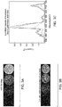
FIG. 1A shows experiments with multiple coatings on buttons. Eu3+ emission became more intense with increasing number of coatings of 2%Eu doping in a gadolinium aluminate coating.FIG. 1B shows inspection of two blades infiltrated with compositions described herein. The blades were placed under short wave UV illumination. Eu fluoresces red under 254 nm UV excitation. Blade 1 is coated evenly except around the leading edge.Blade 1 is coated more evenly thanblade 2. -
FIG. 2 shows evaluation of a blade UV fluorescence image. An initial image of Eu-fluorescence was taken with 254nm excitation. ImageJ3D was used to split the image into component Blue-Green-Red components. An ImageJ 3D plot was used to show Red image intensity. Image Intensity varies over the blade, but the overall variation mimics the airfoil shape. -
FIG. 3A and FIG. 3B show a comparison of x-ray fluorescence (XRF) versus UV data for test buttons which were illuminated with UV illumination or X-ray illumination. UV inspection compares well with XRF.FIG. 3C shows excitation spectra of europium doped with gadolinium aluminate. - Aspects of the present disclosure involve disposing a material within a plurality of surface-connected openings of the ceramic coating. In one group of embodiments, "disposing" a material within a plurality of surface-connected openings of the ceramic coating may be achieved by, for example, spray coating the ceramic-coated substrate. In other embodiments, "disposing" a material within a plurality of surface-connected openings of the ceramic coating involves infiltrating a composition into the openings (e.g., voids, cracks, channels, columns, pores, or cavities) of a ceramic coating such as a thermal barrier coating. Upon heating, the infiltrated composition forms a protective material, typically an oxide, that has the ability to react with CMAS rapidly. The reaction of the infiltrated material (e.g., a sacrificial oxide) with CMAS forms a material that solidifies before the CMAS can significantly penetrate the ceramic coating such as the thermal barrier coating. The infiltrated composition can additionally or alternatively react with the CMAS to increase the viscosity of the CMAS such that the CMAS cannot readily infiltrate into the TBC.
- One desired aspect of infiltrating a material (comprising a protective agent and a phosphor) within a plurality of surface-connected openings of a ceramic coating is to get a uniform deposition of the protective agent into and/or onto the ceramic coating. Inspection of the infiltrated areas is desired to ensure that the application process is uniform and appropriately targeted. In the absence of a uniform dispersion of the protective agent into and/or onto the ceramic-coated substrate, damage from CMAS infiltration into regions of deficient coverage of protective agent may create hot spots in/on the ceramic-coated (e.g., TBC-coated) metal substrate leading to premature component failure.
- Accordingly, provided herein are improved compositions (e.g., compositions suitable for infiltration) that comprise a protective agent (e.g., a barrier agent and/or an anti-CMAS agent which reacts with CMAS) and a phosphor in the composition. By shining a light on the infiltrated component and checking the uniformity and intensity of the light emission caused by the co-infiltrated phosphor compound, the uniformity and concentration of the application of the infiltrated composition can be determined. The methods and compositions described herein allow for identification of a region of insufficient concentration of the protective agent based on the difference in intensity of emission from the region relative to emission in other regions of the ceramic coating, thereby allowing for easy inspection of the components. Thus the present method allows for more efficient quality control and/or targeted maintenance and repair of components coated with ceramic coatings such as thermal barrier coatings.
- As used herein, "surface-connected openings of the ceramic coating" are one or more of voids, cracks, channels, columns, pores, cavities, cooling passages, and the like, and are present in the ceramic coating. Said voids, cracks, channels, columns, pores, cavities, cooling passages, and the like, are a part of the ceramic-coated surface of a component, i.e., they are connected to the surface.
- As used herein, the term "thermal barrier coating" refers to a coating that includes a material capable of substantially reducing heat flow to the underlying substrate of the article, that is, forming a thermal barrier. In some embodiments, the thermal barrier coating includes a material having a melting point greater than about 1000 °C. In some embodiments, the thermal barrier coating includes a material having a melting point greater than about 2000 °C. In some embodiments, the thermal barrier coating includes a material having a melting point in a range from about 2000 °C to about 3000 °C. Examples of ceramic thermal barrier coating materials include and are not limited to various zirconias, in particular chemically stabilized zirconias (for example, metal oxides blended with zirconia), such as yttria-stabilized zirconias, ceria-stabilized zirconias, calcia-stabilized zirconias, scandia-stabilized zirconias, magnesia-stabilized zirconias, india-stabilized zirconias, ytterbia-stabilized zirconias, lanthana-stabilized zirconias, gadolinia-stabilized zirconias, as well as mixtures of such stabilized zirconias.
- As used herein, a "phosphor" includes any luminescent material including a phosphorescent or a fluorescent material.
- As used herein, "infiltration" may be achieved using one or more than one technique including and not limited to infiltration of liquid-based (e.g., aqueous, or solvent-based (e.g., alcohol- based (e.g., ethanol-based))) solutions or suspensions, infiltration of sol gel compositions, electrophoretic depositions (EPD), chemical or physical vapor deposition and the like.
- As used herein, an "anti- calcium-magnesium-aluminum-silicon-oxide agent" or an "anti-CMAS agent" acts as a protective agent for the ceramic coating that reduces or prevents or delays CMAS-inflicted damage to the ceramic coating. An anti-CMAS agent may chemically react with liquid/molten nominal CMAS to form a solid crystalline product. The solid crystalline product has a higher melting temperature than the nominal CMAS composition so that it remains as a solid barrier to liquid/molten nominal CMAS infiltration. Alternatively, an anti-CMAS agent may increase the viscosity of liquid/molten nominal CMAS thereby reducing or preventing or delaying entry of CMAS into the ceramic coating and CMAS-inflicted damage to the ceramic coating.
- An anti-CMAS agent is designed to be highly reactive to CMAS-type material, such that, at typical temperatures where CMAS is encountered in liquid form, the anti-CMAS agent rapidly reacts with the CMAS to form a solid reaction product that itself is thermally and chemically stable in the presence of liquid CMAS; or alternatively, the anti-CMAS agent reacts with molten CMAS and increases the viscosity of the molten CMAS thereby reducing or preventing or delaying ingress of CMAS into the thermal barrier coating.
- For the purposes of this description, the term "nominal CMAS" refers to any CMAS composition which will cause damage to a ceramic coating (e.g., a thermal barrier coating). In an exemplary embodiment, nominal CMAS refers to the following composition, with all percentages in mole percent: 41.6% silica (SiO2), 29.3% calcia (CaO), 12.5% alumina (AlO1.5), 9.1% magnesia (MgO), 6.0% iron oxide (FeO1.5), and 1.5% nickel oxide (NiO). It will be appreciated that the nominal CMAS composition given above is only a representative reference composition to define a benchmark for a substance's CMAS reactivity in a way that can be compared to the CMAS reactivity of other substances; use of this reference composition does not limit in any way the actual composition of ingested material that becomes deposited on the coating during operation which, of course, will vary widely in service.
- As used herein, a "barrier agent" acts as a protective agent for the ceramic coating as follows. When an anti-CMAS agent is disposed (infiltrated) at the interface of the ceramic coating and the underlying bondcoat or substrate, chemical interaction between the rare-earth-bearing anti-CMAS agent and an oxide formed by the bondcoat or substrate at elevated temperature - known as a thermally-grown oxide, or TGO - can result in premature spalling of the ceramic coating. To mitigate this potential issue, some embodiments of the present invention employ a barrier agent disposed to substantially separate the anti-CMAS agent from the bondcoat or, if no bondcoat is present, from the substrate. Thus the barrier agent is interposed between substrate or bondcoated substrate and the anti-CMAS agent. The barrier agent substantially prevents chemical interaction between the anti-CMAS agent and a TGO disposed on the substrate or, if present, the bondcoat on the substrate. In some embodiments, a barrier agent comprises aluminum oxide, cerium oxide, yttrium oxide, zirconium oxide, hafnium oxide, tantalum oxide, niobium oxide, titanium oxide, or combinations thereof. Some of these oxides may, where appropriate, include a sufficient amount of stabilizer (often a rare earth element) to reduce propensity of the oxide to undergo stress-generating phase transformations during heat-up and cool-down, but the amount of rare-earth stabilizer should be sufficiently small to mitigate issues of reactivity with the aforementioned TGO. The upper limit of rare-earth stabilizer content depends on the particular element being used and the identity of the barrier agent; for example, rare earth bearing aluminate garnets tend not to dissolve alumina, and thus may contain higher amounts of rare earth material without deleterious interaction with TGO. In certain embodiments, a barrier agent tends to be less reactive towards aluminum oxide (e.g., a cerium oxide (CeO2) barrier agent). In some embodiments, the barrier agent comprises less than about 40 atomic per cent rare earth element content. In certain embodiments barrier agent comprises less than about 10 atomic per cent rare earth element content, for example as found in the commonly used zirconia stabilized with 8 mole percent yttria ("8YSZ"). The barrier agent material need not be as reactive with CMAS as an anti-CMAS agent, because it is typically separated from contact with CMAS by the anti-CMAS agent. The function of barrier agent, then, is primarily to physically separate the anti-CMAS agent from bondcoat and/or the substrate.
- Accordingly, in a first aspect, provided herein is a method comprising:
- disposing a material in a plurality of surface-connected openings of a ceramic coating, the material comprising
- i. one or more phosphors; and
- ii. one or more protective agents.
- In one embodiment, the method described above further comprises ceratin inspection methods, i.e., methods for determination of uniformity of deposition of the material in the ceramic coating and such methods are described in more detail below. In additional embodiments, various methods for disposing the material in a plurality of surface-connected openings of the ceramic coating are described in more detail below.
- In a second aspect, provided herein are methods for determination of uniformity of deposition of a material in a ceramic coating comprising:
- (a) illuminating a surface of the ceramic coating with a stimulant radiation, wherein the ceramic coating comprises a plurality of surface-connected openings and a material disposed in at least some of the openings, the material comprising
- i. one or more phosphors; and
- ii. one or more protective agents;
- (b) detecting an emission radiation from the material in response to the stimulant radiation; and
- (c) recording the distribution of the material within the ceramic coating based on the intensity of the detected emission radiation as a function of position on the surface.
- As used herein, "recording the distribution of the material within the ceramic coating" refers to obtaining images of parts illuminated with stimulant radiation which emit radiation (e.g., fluoresce) subsequent to illumination with the stimulant radiation. Methods for obtaining such images are known in the art.
- In one embodiment of the methods described herein, the ceramic coating is a thermal barrier coating.
- In one embodiment of the methods described herein, after illumination of the area in which the material is disposed with a stimulant radiation, the wavelength of the light emitted from the one or more disposed phosphors is different from any wavelength of light emitted by the original ceramic coating under the same illumination. In other words, using the methods described herein, a light sensitive phosphor is co-disposed with a protective agent in the surface-connected openings of a ceramic structure and the deposition of material is checked by measuring the difference between the light emitted from the ceramic coating substantially free of phosphor (e.g., the original ceramic coating) and the ceramic coating having an effective amount of a material comprising one or more phosphors disposed in the surface connected openings of the ceramic coating.
- In another embodiment, the methods further comprise identifying regions of insufficient concentration of the material based on the recorded distribution of the material, and disposing an additional quantity of the material in the regions of insufficient concentration of the material.
- Determination of uniformity of the deposition of the material comprising a protective agent and a phosphor comprises, in one embodiment, illuminating with a stimulant radiation and obtaining a color image of the fluorescing part (i.e., an infiltrated substrate) and separating the image into primary colors. The camera images are processed using ImageJ software. The color images obtained using the emitted light are broken down into their primary color components, and the red intensity plotted for the specimens under observation. Image intensity in a particular wavelength, for example, red light, is examined to determine the coating amount and/or the uniformity of the coating. Fluorescence intensity can be mapped as a function of geometry to estimate concentration of the phosphor dopant across the surface of the coated article.
- In one embodiment, the ceramic coating, subsequent to deposition of a material comprising a protective agent and a phosphor, is illuminated with a stimulant radiation which is ultra-violet (UV) light. It will be understood that any suitable form of illumination / stimulant radiation may be used and may be matched to any suitable phosphor present in the disposed material. Contemplated within the scope of embodiments presented herein is X-ray fluorescence, that is, illumination of the ceramic coating, subsequent to deposition of a material comprising a protective agent and a phosphor, with high-energy X-rays or gamma rays and evaluating the emission of secondary (fluorescent) x-rays. In short, "illuminating" or "illuminating with a stimulant radiation" as used herein means supplying any form of electromagnetic radiation, such as but not limited to gamma rays, X-rays, visible light, near infrared light, ultraviolet light and the like. Similarly, the term "light" as used herein means any form of electromagnetic radiation and is not limited to visible wavelengths.
- In certain embodiments, the phosphor is present in the material in an amount from about 0.1% to about 5% by weight of the material. In other embodiments, the phosphor is present in the material in an amount from about 0.1% to about 2.5% by weight of the material.
- The phosphor comprises a host and an activator, typically chosen to provide a phosphor that avoids substantial overlap with emissions from any other phosphor that may be present in the ceramic coating itself. The host is typically a wide band gap material and the activator is an ion where the excitation and emission occur. The activator is typically chosen so that the emitted light is in the visible range, near infrared or near-UV range. The host holds the activator ions in place so that the activator ions do not cluster and undergo concentration quenching. By way of example, an activator for a phosphor described herein may comprise one or more of copper, added in concentration of 5 ppm to 20 mol% copper-activated zinc sulfide, silver, added to zinc sulfide, europium(II) added to strontium aluminate, cerium, added to yttrium aluminium garnet, and the like. By way of example, a host for an activator for any phosphor described herein may comprise one or more of oxides, nitrides, oxynitrides, sulfides, selenides, halides or silicates of zinc, cadmium, manganese, aluminium, silicon, sulfur, phosphorous, or various rare earth metals.
- In one group of embodiments, the phosphor comprises one or more of europium, tungsten, molybdenum, lead, boron, titanium, manganese, uranium, chromium, terbium, dysprosium, yttrium, cerium, gadolinium, lanthanum, phosphorous, oxygen, lutetium or nitrogen.
- In a specific embodiment, the phosphor includes europium. In one instance, the europium is present in the material in an amount from about 0.1% to about 5% by weight of the material. Alternatively, the europium is present in the material in an amount from about 0.1% to about 2.5% by weight of the material.
- In one group of embodiments, the protective agent includes a barrier agent, an anti- calcium-magnesium-aluminum-silicon-oxide (CMAS) agent, or a combination thereof. In some of such embodiments, the material comprises a barrier agent and a phosphor. In some other such embodiments, the material comprises an anti-CMAS agent and a phosphor.
- In one embodiment of the methods described herein, in a first quantity, the disposed material comprises one or more barrier agents; and in a second quantity, the disposed material comprises one or more anti-CMAS agents.
- In one embodiment of the methods described herein, in a first quantity, the disposed material comprises one or more barrier agents and a first phosphor, and in a second quantity, the disposed material comprises one or more anti-CMAS agents and a second phosphor; wherein, after illumination of the area in which the one or more quantities of the material is disposed with a stimulant radiation, the wavelength of the light emitted from the first phosphor is different from the wavelength of light emitted by the second phosphor. Further, the wavelengths of light emitted by the first and second phosphors are different from any wavelengths of light which may be emitted by the ceramic coating itself (e.g., where the ceramic coating itself comprises a phosphor).
- Also contemplated herein are embodiments wherein the disposed material comprises the barrier agent and the anti-CMAS agent in the same composition along with one or more phosphors. Further, in certain instances, an anti-CMAS agent or a barrier agent may itself be a phosphor as well.
- In one group of embodiments, the protective agent is an anti-CMAS agent comprising one or more rare earth elements or alkaline earth elements, or a combination thereof. In some of such embodiments, the one or more rare earth elements are selected from the group consisting of lanthanum, neodymium, erbium, cerium, and gadolinium. In some of such embodiments, the one or more alkaline earth elements are selected from the group consisting of beryllium, magnesium, calcium, strontium, barium, and radium.
- In one group of embodiments, the anti-CMAS agent comprises a nitride, an oxide, or combinations thereof. In some of such embodiments, the anti-CMAS agent comprises nitrides of rare earth elements or alkaline earth elements, oxides of rare earth elements or alkaline earth elements, or combinations thereof. In another group of embodiments, the anti-CMAS agent further comprises zirconium, hafnium, titanium, tantalum, or niobium.
- In one embodiment, the anti-CMAS agent comprises a rare-earth element, oxygen, and an element selected from the group consisting of tantalum and niobium. In another embodiment, the anti-CMAS agent has a nominal formula A3BX7, wherein A comprises a rare earth metal element, B comprises tantalum, niobium, or combinations thereof, and X comprises oxygen, fluorine, or combinations thereof.
- In one embodiment, the anti-CMAS agent has a weberite crystal structure and comprises gadolinium, oxygen, and at least one element selected from the group consisting of tantalum and niobium. In another embodiment, the anti-CMAS agent comprises an oxide having the nominal formula A1-xBxZr4-yDy(PO4)z;
wherein A and B are selected from the group consisting of alkaline earth metals and rare earth metals, D is hafnium or titanium, x is a number from 0 to 1; y is a number from 0 to 4; and z is 3 or 6. - In one embodiment, the anti-CMAS agent comprises MZr4(PO4)6, wherein M comprises at least one alkaline earth metal. In another embodiment, the anti-CMAS agent comprises CaxSr1-x Zr4(PO4)6, wherein x is a number from 0 to 1. In some of such embodiments, the anti-CMAS agent comprises CaZr4(PO4)6, Sr Zr4(PO4)6, Ca0.5Sr0.5Zr4(PO4)6, or combinations thereof.
- In one embodiment, the anti-CMAS agent has a perovskite crystal structure and comprises (a) a rare earth element, (b) tantalum, niobium, or a combination of tantalum and niobium, and (c) oxygen. In another embodiment, the anti-CMAS agent comprises gadolinium, tantalum, and oxygen.
- In one embodiment, the anti-CMAS agent comprises a compound having a scheelite, fergusonite, or wolframite crystal structure, and having a nominal formula ABX4, wherein A comprises a rare-earth element, B comprises tantalum, niobium, or a combination of tantalum and niobium, and X comprises oxygen, nitrogen, or a combination of nitrogen and oxygen. In some of such embodiments, A comprises yttrium, gadolinium, lanthanum, neodymium, ytterbium, or a combination thereof.
- In one group of embodiments, the protective agent includes a barrier agent comprising aluminum oxide, hafnium oxide or cerium oxide, or a combination thereof. In some of such embodiments, the barrier agent comprises Al2O3, HfO2, Ce2O3, or a combination thereof. In some other such embodiments, the barrier agent comprises Ce2O3.
- In certain embodiments, the protective agent is selected from the group consisting of GdAlO3, Gd3NbO7, and GdTa3O9.
- In certain embodiments, the material disposed within the surface connected openings of the ceramic coating comprises 1.5 weight% of Eu2O3 by total weight of the material; in such embodiments, the europium oxide is a phosphor and the material optionally further comprises an anti-CMAS agent, or a barrier agent, or a combination thereof.
- In certain embodiments, the material disposed within the surface connected openings of the ceramic coating comprises Gd0.98Eu0.02AlO3; where the material includes a phosphor and an anti-CMAS agent.
- In one instance, disposing the material within the ceramic coating comprises infiltrating the surface connected openings of the ceramic coating with a liquid. In such embodiments, the liquid comprises a carrier fluid and a plurality of particles suspended within the carrier fluid. Alternatively, the liquid comprises a solvent and a solute dissolved in the solvent.
- In some embodiments, infiltrating the material as a liquid further comprises volatilizing the liquid to form a residue disposed in the surface-connected openings of the ceramic coating.
- In another aspect, provided herein is a ceramic coating comprising a protective agent and a phosphor disposed in its surface-connected openings. In one embodiment, the ceramic coating is a thermal barrier coating. In some embodiments, the protective agent is a barrier agent, an anti- calcium-magnesium-aluminum-silicon-oxide (CMAS) agent, or a combination thereof, where the protective agent is as described above.
- The ceramic coatings (e.g., thermal barrier coatings) are typically deposited or otherwise formed on a bond coating (if present) or on the substrate directly by any of a variety of conventional techniques, including vapor deposition, such as physical vapor deposition (PVD), electron beam physical vapor deposition (EBPVD); plasma spray, such as air plasma spray (APS), suspension plasma spray (SPS), and vacuum plasma spray (VPS); other thermal spray deposition methods such as high velocity oxy-fuel (HVOF) spray, detonation, or wire spray; chemical vapor deposition (CVD), sol-gel method, or combinations of two or more of the afore-mentioned techniques.
- Ceramic coatings, including thermal barrier coatings, typically comprise surface connected openings such as pores, channels or other cavities that, during subsequent operation, are infiltrated by molten environmental contaminants, such as, CMAS. In some instances, such pores, channels, or cavities are created by environmental damage or the normal wear and tear during operation of the ceramic coatings (e.g., thermal barrier coatings). In some instances, the surface openings in a ceramic coating arise from the deposition processes. For example, thermal barrier coatings deposited by (air) plasma spray techniques may comprise a sponge-like porous structure of open pores in at least the surface of the coating. Similarly, thermal barrier coatings that are deposited by physical (e.g., chemical) vapor deposition techniques may comprise a porous structure including a series of columnar grooves, crevices or channels in at least the surface of the coating. While the porous structure provides for strain tolerance by ceramic coatings during thermal cycling, and further provides for stress reduction due to the differences between the coefficient of thermal expansion (CTE) of the coating and the CTE of the underlying bond coat layer/substrate, the inherent porous structure is also vulnerable to infiltration by molten environmental contaminants such as CMAS.
- The type of substrate may depend in part on the turbine component. Non-limiting examples of suitable substrates include metals, metal alloys, or combinations thereof. In certain embodiments, the substrate includes an alloy of nickel, cobalt, iron, or combinations thereof. For example, the substrate may include a high temperature, heat-resistant alloy, e.g., a superalloy. Non-limiting examples of suitable high temperature nickel-based alloys include Inconel®, Nimonic®, Rene® (e.g., Rene® 80, Rene® 95 alloys), Udimet®, or combinations thereof. By way of non-limiting examples, the substrate may comprise one or more of nickel-base superalloys, cobalt-base superalloys, and ceramic matrix composites, and the like.
- The optional bond coating may be formed from a metallic oxidation-resistant material that protects the underlying substrate and enables the thermal barrier coating to more tenaciously adhere to substrate. Bond coats provide functionality-adhesion promotion and oxidation resistance. Suitable materials for the bond coating include M1CrAlY alloy powders, where M1 represents a metal such as iron, nickel, platinum or cobalt. Bondcoats are especially useful when applied to a metallic substrates comprising superalloys. In other embodiments, bondcoats comprise silicide compounds or elemental silicon, which are often associated with ceramic-based substrates, such as silicon carbide-reinforced silicon carbide ceramic matrix composites (CMC's). Bond coatings are applied using any of various coating techniques known in the art, such as plasma spray, thermal spray, chemical vapor deposition, or physical vapor deposition. Non-limiting examples of suitable bond coat materials include metal aluminides such as nickel aluminide, platinum aluminide, or combinations thereof. The bond coating may have a thickness in the range of from about 25 microns to about 500 microns.
- As used herein, a material is considered resistant to CMAS infiltration in this context if it is more resistant, relative to 8 mole percent yttria stabilized zirconia (8YSZ), to infiltration by liquid CMAS having the nominal CMAS composition described previously herein at a temperature of 1300 degrees Celsius. It will be appreciated that the 1300 degree Celsius temperature and the nominal CMAS composition represent a reference temperature and a reference composition to define a benchmark for the material's CMAS resistance in a way that can be compared to the CMAS resistance of 8YSZ; use of these reference values does not limit in any way the actual temperature at which any ceramic-coated article may operate or the actual composition of ingested material that becomes deposited on the coating during operation, both of which, of course, will vary widely in service.
- The methods described herein are suitable for protection and/or inspection of a wide variety of components (e.g., turbine engine components) that are operated at, or exposed to, high temperatures. Non-limiting examples of suitable turbine engine components include turbine airfoils such as blades and vanes, turbine shrouds, turbine nozzles, buckets, combustor components such as liners and deflectors, heat shields, augmentor hardware of gas turbine engines, and the like. The material comprising a protective agent and a phosphor is disposed over a portion or over all of the metal substrate. By way of illustration only, with regard to airfoils such as blades, the material is typically used to protect, cover or overlay portions of the metal substrate of the airfoil other than solely the tip thereof, for example, the thermal barrier coatings cover the leading and trailing edges and other surfaces of the airfoil.
- Europium nitrate hexahydrate was added to an anti-CMAS agent solution (1M GdAlO3 from aqueous nitrates) such that the molar ratio of Eu/Gd was 0.02. The solution was applied uniformly to various TBC coated specimens. The applications were repeated as needed with an 80 degree C air dry, and 700 degree C air bake to create a set of samples with various loadings of the phosphor doped anti-CMAS agent. Fluorescence of the agent was observed using a 254nm ultraviolet illumination source (UVGL-25, 4w 254/365nm, PN 95-0021-12, UVP LLC, Upland CA, www.uvp.com) and detected using a Nikon D80 camera with a AF-S 18-135mm Nikkor lens with fixed exposure conditions. The camera images were processed using ImageJ software. The color images obtained using the emitted light were broken down into their primary color components, and the red intensity plotted for the specimens under observation.
- In the first example, PVD TBC coated buttons were coated with 0, 2, 6, or 10 solution applications. UV illumination of the buttons caused the infiltrated phosphor to emit light within the expected wavelength region, allowing determination of coating uniformity, coverage and concentration on the buttons.
- In a second example, a PVD TBC-coated turbine blade was masked and coated with up to 10 solution applications in specific areas. UV illumination of the blade caused the infiltrated phosphor to emit light within the expected wavelength region, allowing determination of coating uniformity, coverage and concentration on the blade airfoil.
- While only certain features of the invention have been illustrated and described herein, many modifications and changes will occur to those skilled in the art. It is, therefore, to be understood that the appended claims are intended to cover all such modifications and changes as fall within the true spirit of the invention.
- Various aspects and embodiments of the present invention are defined in the following clauses:
- 1. A method comprising:
- disposing a material in a plurality of surface-connected openings of a ceramic coating, the material comprising
- i. one or more phosphors; and
- ii. one or more protective agents.
- disposing a material in a plurality of surface-connected openings of a ceramic coating, the material comprising
- 2. A method for determination of uniformity of deposition of a material in a ceramic coating comprising:
- (a) illuminating a surface of the ceramic coating with a stimulant radiation, wherein the ceramic coating comprises a plurality of surface-connected openings and a material disposed in at least some of the openings, the material comprising
- i. one or more phosphors; and
- ii. one or more protective agents;
- (b) detecting an emission radiation from the material in response to the stimulant radiation; and
- (c) recording the distribution of the material within the ceramic coating based on the intensity of the detected emission radiation as a function of position on the surface.
- (a) illuminating a surface of the ceramic coating with a stimulant radiation, wherein the ceramic coating comprises a plurality of surface-connected openings and a material disposed in at least some of the openings, the material comprising
- 3. The method of
clause 2, wherein the ceramic coating is a thermal barrier coating. - 4. The method of
clause 2, wherein, after illumination of the area in which the material is disposed with a stimulant radiation, the wavelength of the light emitted from the one or more disposed phosphors is different from any wavelength of light emitted by the original ceramic coating under the same illumination. - 5. The method of
clause 2, further comprising identifying regions of insufficient concentration of the material based on the recorded distribution of the material, and disposing an additional quantity of the material in the regions of insufficient concentration of the material. - 6. The method of
clause 2, wherein the stimulant radiation is ultra-violet (UV) light. - 7. The method of
clause 2, wherein the phosphor is present in the material in an amount from about 0.1% to about 5% by weight of the material. - 8. The method of
clause 2, wherein the phosphor is present in the material in an amount from about 0.1% to about 2.5% by weight of the material. - 9. The method of
clause 2, wherein the phosphor comprises a host and an activator. - 10. The method of
clause 2, wherein the phosphor comprises one or more of europium, tungsten, molybdenum, lead, boron, titanium, manganese, uranium, chromium, terbium, dysprosium, yttrium, cerium, gadolinium, lanthanum, phosphorous, oxygen, lutetium or nitrogen. - 11. The method of clause 10, wherein the phosphor contains europium.
- 12. The method of clause 11, wherein the europium is present in the material in an amount from about 0.1% to about 5% by weight of the material.
- 13. The method of clause 11, wherein the europium is present in the material in an amount from about 0.1% to about 2.5% by weight of the material.
- 14. The method of
clause 2, wherein the protective agent is a barrier agent, an anti- calcium-magnesium-aluminum-silicon-oxide (CMAS) agent, or a combination thereof. - 15. The method of
clause 2, wherein the material comprises a barrier agent and a phosphor. - 16. The method of
clause 2, wherein the material comprises an anti-CMAS agent and a phosphor. - 17. The method of clause 14, wherein, in a first quantity, the disposed material comprises one or more barrier agents; and in a second quantity, the disposed material comprises one or more anti-CMAS agents.
- 18. The method of clause 17, wherein in a first quantity, the disposed material comprises one or more barrier agents and a first phosphor, and in a second quantity, the disposed material comprises one or more anti-CMAS agents and a second phosphor; wherein, after illumination of the area in which the one or more quantities of the material is disposed with a stimulant radiation, the wavelength of the light emitted from the first phosphor is different from the wavelength of light emitted by the second phosphor.
- 19. The method of clause 14, wherein the anti-CMAS agent comprises one or more rare earth elements or alkaline earth elements, or a combination thereof.
- 20. The method of clause 19, wherein the one or more rare earth elements are selected from the group consisting of lanthanum, neodymium, erbium, cerium, and gadolinium.
- 21. The method of clause 19, wherein the one or more alkaline earth elements are selected from the group consisting of beryllium, magnesium, calcium, strontium, barium, and radium.
- 22. The method of clause 19, wherein the anti-CMAS agent comprises a nitride, an oxide, or combinations thereof.
- 23. The method of clause 19, wherein the anti-CMAS agent further comprises zirconium, hafnium, titanium, tantalum, or niobium.
- 24. The method of clause 14, where in the barrier agent comprises aluminum oxide, hafnium oxide or cerium oxide, or a combination thereof.
- 25. The method of clause 14, where in the barrier agent comprises Al2O3, HfO2, Ce2O3, or a combination thereof.
- 26. The method of
clause 2, wherein the protective agent is selected from the group consisting of GdAlO3, Gd3NbO7, and GdTa3O9. - 27. The method of
clause 2, wherein the material comprises 1.5 weight% of Eu2O3 by total weight of the material. - 28. The method of
clause 2, wherein the material comprises Gd0.98Eu0.02AlO3. - 29. The method of
clause 2, wherein disposing the material within the ceramic coating comprises infiltrating the surface connected openings of the ceramic coating with a liquid. - 30. The method of clause 29, wherein the liquid comprises a carrier fluid and a plurality of particles suspended within the carrier fluid.
- 31. The method of clause 29, wherein the liquid comprises a solvent and a solute dissolved in the solvent.
- 32. The method of clause 29, further comprising volatilizing the liquid to form a residue disposed in the surface-connected openings of the ceramic coating.
- 33. A ceramic coating comprising a protective agent and a phosphor disposed in its surface connected openings.
- 34. The ceramic coating of clause 33, wherein the ceramic coating is a thermal barrier coating.
- 35. The ceramic coating of clause 33, wherein the protective agent is a barrier agent, an anti- calcium-magnesium-aluminum-silicon-oxide (CMAS) agent, or a combination thereof.
Claims (15)
- A method comprising:disposing a material in a plurality of surface-connected openings of a ceramic coating, the material comprisingi. one or more phosphors; andii. one or more protective agents.
- A method for determination of uniformity of deposition of a material in a ceramic coating comprising:(a) illuminating a surface of the ceramic coating with a stimulant radiation, wherein the ceramic coating comprises a plurality of surface-connected openings and a material disposed in at least some of the openings, the material comprisingi. one or more phosphors; andii. one or more protective agents;(b) detecting an emission radiation from the material in response to the stimulant radiation; and(c) recording the distribution of the material within the ceramic coating based on the intensity of the detected emission radiation as a function of position on the surface.
- The method of claim 2, wherein, after illumination of the area in which the material is disposed with a stimulant radiation, the wavelength of the light emitted from the one or more disposed phosphors is different from any wavelength of light emitted by the original ceramic coating under the same illumination.
- The method of claim 2, further comprising identifying regions of insufficient concentration of the material based on the recorded distribution of the material, and disposing an additional quantity of the material in the regions of insufficient concentration of the material.
- The method of claim 2, wherein the phosphor is present in the material in an amount from 0.1% to 5% by weight of the material, preferably in an amount from 0.1% to 2.5% by weight of the material.
- The method of claim 1 or 2, wherein the phosphor comprises a host and an activator.
- The method of claim 1 or 2, wherein the phosphor comprises one or more of europium, tungsten, molybdenum, lead, boron, titanium, manganese, uranium, chromium, terbium, dysprosium, yttrium, cerium, gadolinium, lanthanum, phosphorous, oxygen, lutetium or nitrogen.
- The method of claim 7, wherein the phosphor contains europium and europium is present in the material in an amount from 0.1% to 5% by weight of the material, preferably in an amount from about 0.1% to about 2.5% by weight of the material.
- The method of claim 1 or 2, wherein the protective agent is a barrier agent, an anti- calcium-magnesium-aluminum-silicon-oxide (CMAS) agent, or a combination thereof.
- The method of claim 9, wherein, in a first quantity, the disposed material comprises one or more barrier agents; and in a second quantity, the disposed material comprises one or more anti-CMAS agents.
- The method of claim 9 or 10, wherein the anti-CMAS agent comprises one or more rare earth elements or alkaline earth elements, or a combination thereof.
- The method of claim 9, where in the barrier agent comprises aluminum oxide, hafnium oxide or cerium oxide, or a combination thereof.
- The method of claim 1 or 2, wherein the protective agent is selected from the group consisting of GdAlO3, Gd3NbO7, and GdTa3O9.
- The method of claim 1 or 2, wherein the material comprises 1.5 weight% of Eu2O3 by total weight of the material or wherein the material comprises Gd0.98Eu0.02AlO3.
- A ceramic coating comprising a protective agent and a phosphor disposed in its surface connected openings.
Applications Claiming Priority (1)
| Application Number | Priority Date | Filing Date | Title |
|---|---|---|---|
| US14/963,256 US10201831B2 (en) | 2015-12-09 | 2015-12-09 | Coating inspection method |
Publications (2)
| Publication Number | Publication Date |
|---|---|
| EP3182100A1 true EP3182100A1 (en) | 2017-06-21 |
| EP3182100B1 EP3182100B1 (en) | 2025-04-30 |
Family
ID=57737541
Family Applications (1)
| Application Number | Title | Priority Date | Filing Date |
|---|---|---|---|
| EP16202590.2A Active EP3182100B1 (en) | 2015-12-09 | 2016-12-07 | Coating inspection method |
Country Status (6)
| Country | Link |
|---|---|
| US (1) | US10201831B2 (en) |
| EP (1) | EP3182100B1 (en) |
| JP (1) | JP6409042B2 (en) |
| CN (1) | CN107037065B (en) |
| BR (1) | BR102016028786A2 (en) |
| CA (1) | CA2950548C (en) |
Families Citing this family (17)
| Publication number | Priority date | Publication date | Assignee | Title |
|---|---|---|---|---|
| US20170198601A1 (en) * | 2016-01-12 | 2017-07-13 | United Technologies Corporation | Internally cooled ni-base superalloy component with spallation-resistant tbc system |
| US10641720B2 (en) | 2017-10-06 | 2020-05-05 | General Electric Company | Thermal barrier coating spallation detection system |
| JP6767351B2 (en) * | 2017-12-18 | 2020-10-14 | 株式会社三共 | Game machine |
| US10837918B2 (en) * | 2018-03-23 | 2020-11-17 | Deutsches Zentrum Für Luft-Und Raumfahrt E.V | Non-destructive CMAS-infiltration characterization of thermal barrier coatings |
| CN108588011B (en) * | 2018-05-08 | 2022-04-05 | 中国农业科学院北京畜牧兽医研究所 | A method for improving in vitro fertilization ability of vitrified oocytes |
| US11028486B2 (en) * | 2018-12-04 | 2021-06-08 | General Electric Company | Coating systems including infiltration coatings and reactive phase spray formulation coatings |
| CN109580569A (en) * | 2018-12-28 | 2019-04-05 | 蜂巢能源科技有限公司 | The detection device of coating slurry |
| CN110231324A (en) * | 2019-07-15 | 2019-09-13 | 天津大学 | Boundary defect detection system and method |
| CN110501105A (en) * | 2019-09-17 | 2019-11-26 | 西安交通大学 | A kind of non-destructive measuring method of the neighbouring ceramic layer residual stress in thermal barrier coating interface |
| US12365803B2 (en) | 2020-06-19 | 2025-07-22 | General Electric Company | Inspectable coatings and methods for using |
| CN111998789B (en) * | 2020-07-09 | 2022-05-10 | 北京金轮坤天特种机械有限公司 | Thermal barrier coating spraying quality evaluation and control method |
| CN112757796B (en) * | 2020-12-30 | 2022-04-08 | 华中科技大学 | System and method for detecting quality of display device in whole spray printing manufacturing process |
| US11988471B2 (en) | 2021-03-27 | 2024-05-21 | Massachusetts Institute Of Technology | Devices and methods for fabrication of components of a multiscale porous high-temperature heat exchanger |
| US12319834B2 (en) | 2021-12-17 | 2025-06-03 | General Electric Company | Anti-corrosion material and application method |
| US12394804B2 (en) | 2022-08-16 | 2025-08-19 | General Electric Company | Thermal management of a fuel cell assembly |
| CN115716034B (en) * | 2022-11-30 | 2023-11-24 | 联宝(合肥)电子科技有限公司 | Coating preparation method and coating |
| US12560562B2 (en) | 2023-09-15 | 2026-02-24 | General Electric Company | Inspection apparatus and method for inspecting a component |
Citations (4)
| Publication number | Priority date | Publication date | Assignee | Title |
|---|---|---|---|---|
| US20030115941A1 (en) * | 2001-12-20 | 2003-06-26 | General Electric Crd | Thermal barrier coatings, components, method and apparatus for determining past-service conditions and remaining life thereof |
| US20070134518A1 (en) * | 2003-08-18 | 2007-06-14 | Feist Joerg | Coatings and a method of optically detecting corrosion in coatings |
| US20090110953A1 (en) * | 2007-10-29 | 2009-04-30 | General Electric Company | Method of treating a thermal barrier coating and related articles |
| US20090122832A1 (en) * | 2005-08-24 | 2009-05-14 | Jorg Peter Feist | Measurement, coating and monitoring system and method |
Family Cites Families (45)
| Publication number | Priority date | Publication date | Assignee | Title |
|---|---|---|---|---|
| US3675015A (en) | 1969-09-02 | 1972-07-04 | Weyerhaeuser Co | Abhesive pattern detector system |
| US3930063A (en) | 1973-08-23 | 1975-12-30 | Nalco Chemical Co | Correcting for non-uniformity of a silica sol coating |
| US4327155A (en) | 1980-12-29 | 1982-04-27 | General Electric Company | Coated metal structures and method for making |
| FI68320C (en) * | 1982-12-01 | 1985-08-12 | Valtion Teknillinen | FOERFARANDE Før by means of the ATT STRAOLNING FRAON A RADIOISOTOPKAELLA utan att FOERSTOERA sample was MAETA FOERDELNINGEN fyll audio-and / or BELAEGGNINGSMEDEL I TJOCKLEKSRIKTNINGEN audio PAPP ERARTONG or the like OCH Halten from these two MEDEL arranged RGAFOER TILLAEMPANDE audio FOERFARANDET SAMT ANVAENDNINGAR of devices for the AV ERFOARANDET OCH |
| JPS62207885A (en) | 1986-03-07 | 1987-09-12 | Toshiba Corp | High temperature heat resistant member |
| DE3610429A1 (en) * | 1986-03-27 | 1987-10-01 | Boehringer Mannheim Gmbh | Coagulation-neutral, hydrophilic glass fibers |
| US5087670A (en) | 1986-07-10 | 1992-02-11 | Minnesota Mining And Manufacturing Company | Process for fluorimetric monitoring of functional coatings and compositions and fluorescent agents therefor |
| US4922113A (en) | 1986-07-10 | 1990-05-01 | Minnesota Mining And Manufacturing Company | Process for fluorimetric monitoring of functional coatings and compositions and fluorescent agents therefor |
| US5773141A (en) | 1995-04-06 | 1998-06-30 | General Electric Company | Protected thermal barrier coating composite |
| US5683825A (en) | 1996-01-02 | 1997-11-04 | General Electric Company | Thermal barrier coating resistant to erosion and impact by particulate matter |
| US5902670A (en) | 1997-06-04 | 1999-05-11 | Ripstein; Jacqueline | Multi-layered painting and method therefor |
| JP3664004B2 (en) | 1999-11-25 | 2005-06-22 | 松下電工株式会社 | Coating film detection method |
| JP4535677B2 (en) * | 2000-10-17 | 2010-09-01 | ナノグラム・コーポレイション | Coating film production by reactive deposition |
| US7022263B2 (en) | 2002-06-12 | 2006-04-04 | General Electric Company | Europium-activated phosphors containing oxides of rare-earth and group-IIIB metals and method of making the same |
| US20040115470A1 (en) | 2002-12-12 | 2004-06-17 | Ackerman John Frederick | Thermal barrier coating protected by infiltrated alumina and method for preparing same |
| US7094450B2 (en) * | 2003-04-30 | 2006-08-22 | General Electric Company | Method for applying or repairing thermal barrier coatings |
| US7150926B2 (en) | 2003-07-16 | 2006-12-19 | Honeywell International, Inc. | Thermal barrier coating with stabilized compliant microstructure |
| US7271894B2 (en) | 2003-10-01 | 2007-09-18 | General Electric Company | Imaging system for robotically inspecting gas turbine combustion components |
| US20050158460A1 (en) | 2004-01-21 | 2005-07-21 | Williams Christopher C. | Method for protecting new/used engine parts |
| US7601276B2 (en) * | 2004-08-04 | 2009-10-13 | Intematix Corporation | Two-phase silicate-based yellow phosphor |
| US7416788B2 (en) | 2005-06-30 | 2008-08-26 | Honeywell International Inc. | Thermal barrier coating resistant to penetration by environmental contaminants |
| US7780832B2 (en) * | 2005-11-30 | 2010-08-24 | General Electric Company | Methods for applying mitigation coatings, and related articles |
| US7807231B2 (en) | 2005-11-30 | 2010-10-05 | General Electric Company | Process for forming thermal barrier coating resistant to infiltration |
| US7579087B2 (en) * | 2006-01-10 | 2009-08-25 | United Technologies Corporation | Thermal barrier coating compositions, processes for applying same and articles coated with same |
| US7622195B2 (en) | 2006-01-10 | 2009-11-24 | United Technologies Corporation | Thermal barrier coating compositions, processes for applying same and articles coated with same |
| CN101152778A (en) * | 2006-09-27 | 2008-04-02 | 中国航天科技集团公司第五研究院第五一○研究所 | A variable emissivity thermal control coating and its plating method |
| US8062759B2 (en) * | 2007-12-27 | 2011-11-22 | General Electric Company | Thermal barrier coating systems including a rare earth aluminate layer for improved resistance to CMAS infiltration and coated articles |
| US20090184280A1 (en) | 2008-01-18 | 2009-07-23 | Rolls-Royce Corp. | Low Thermal Conductivity, CMAS-Resistant Thermal Barrier Coatings |
| US20090186237A1 (en) * | 2008-01-18 | 2009-07-23 | Rolls-Royce Corp. | CMAS-Resistant Thermal Barrier Coatings |
| EP2128299B1 (en) | 2008-05-29 | 2016-12-28 | General Electric Technology GmbH | Multilayer thermal barrier coating |
| US20100081009A1 (en) | 2008-09-26 | 2010-04-01 | General Electric Company | Spray Application of Liquid Precursors for CMAS Resistant Coatings |
| US8470460B2 (en) | 2008-11-25 | 2013-06-25 | Rolls-Royce Corporation | Multilayer thermal barrier coatings |
| US8658291B2 (en) | 2008-12-19 | 2014-02-25 | General Electric Company | CMAS mitigation compositions, environmental barrier coatings comprising the same, and ceramic components comprising the same |
| EP2233600B1 (en) * | 2009-03-26 | 2020-04-29 | Ansaldo Energia Switzerland AG | Method for the protection of a thermal barrier coating system and a method for the renewal of such a protection |
| DE102009019166B3 (en) * | 2009-04-23 | 2010-12-02 | Axo Dresden Gmbh | Method for producing a reference body for X-ray fluorescence investigations on substrates and reference bodies produced by the method |
| US8692887B2 (en) * | 2010-08-27 | 2014-04-08 | General Electric Company | Thermal imaging method and apparatus for evaluating coatings |
| JP5656528B2 (en) | 2010-09-15 | 2015-01-21 | 三菱重工業株式会社 | High temperature resistant member and gas turbine |
| ITMI20111260A1 (en) | 2011-07-06 | 2013-01-07 | Carmelo Cutrupi | TOPIC COMPOSITIONS FOR USE IN PREVENTION AND / OR IN THE TREATMENT OF DERMATITES |
| US9034479B2 (en) | 2011-10-13 | 2015-05-19 | General Electric Company | Thermal barrier coating systems and processes therefor |
| JP5657048B2 (en) | 2013-03-19 | 2015-01-21 | 三菱重工業株式会社 | High temperature resistant member and gas turbine |
| FR3004712B1 (en) | 2013-04-19 | 2015-05-08 | Herakles | PROCESS FOR MANUFACTURING COMPOSITE MATERIAL WITH CARBIDE MATRIX |
| DE102013213742A1 (en) | 2013-07-12 | 2015-01-15 | MTU Aero Engines AG | CMAS-INERTE HEAT INSULATION LAYER AND METHOD FOR THE PRODUCTION THEREOF |
| WO2015116300A2 (en) | 2013-12-06 | 2015-08-06 | United Technologies Corporation | Calcium-magnesium alumino-silicate (cmas) resistant thermal barrier coatings, systems, and methods of production thereof |
| US10179945B2 (en) | 2013-12-16 | 2019-01-15 | General Electric Company | CMAS resistant thermal barrier coatings |
| US9869188B2 (en) | 2014-12-12 | 2018-01-16 | General Electric Company | Articles for high temperature service and method for making |
-
2015
- 2015-12-09 US US14/963,256 patent/US10201831B2/en active Active
-
2016
- 2016-11-30 JP JP2016231925A patent/JP6409042B2/en active Active
- 2016-12-01 CA CA2950548A patent/CA2950548C/en active Active
- 2016-12-07 EP EP16202590.2A patent/EP3182100B1/en active Active
- 2016-12-08 BR BR102016028786-3A patent/BR102016028786A2/en not_active Application Discontinuation
- 2016-12-09 CN CN201611128506.6A patent/CN107037065B/en active Active
Patent Citations (4)
| Publication number | Priority date | Publication date | Assignee | Title |
|---|---|---|---|---|
| US20030115941A1 (en) * | 2001-12-20 | 2003-06-26 | General Electric Crd | Thermal barrier coatings, components, method and apparatus for determining past-service conditions and remaining life thereof |
| US20070134518A1 (en) * | 2003-08-18 | 2007-06-14 | Feist Joerg | Coatings and a method of optically detecting corrosion in coatings |
| US20090122832A1 (en) * | 2005-08-24 | 2009-05-14 | Jorg Peter Feist | Measurement, coating and monitoring system and method |
| US20090110953A1 (en) * | 2007-10-29 | 2009-04-30 | General Electric Company | Method of treating a thermal barrier coating and related articles |
Also Published As
| Publication number | Publication date |
|---|---|
| CN107037065A (en) | 2017-08-11 |
| BR102016028786A2 (en) | 2017-10-10 |
| CA2950548C (en) | 2019-03-26 |
| CN107037065B (en) | 2021-06-22 |
| JP2017113748A (en) | 2017-06-29 |
| US10201831B2 (en) | 2019-02-12 |
| CA2950548A1 (en) | 2017-06-09 |
| EP3182100B1 (en) | 2025-04-30 |
| US20170165708A1 (en) | 2017-06-15 |
| JP6409042B2 (en) | 2018-10-17 |
Similar Documents
| Publication | Publication Date | Title |
|---|---|---|
| EP3182100B1 (en) | Coating inspection method | |
| EP2962844B1 (en) | Visual indicator of coating thickness | |
| JP5671201B2 (en) | Barrier coating including taggant and parts having the same | |
| US9920417B2 (en) | Article and method of making thereof | |
| EP1595977A2 (en) | Superalloy article having corrosion resistant coating thereon | |
| US20090162561A1 (en) | Methods for making barrier coatings comprising taggants and components having the same | |
| EP4194429B1 (en) | Thermal and environmental barrier coating compositions and methods of deposition | |
| US20090162533A1 (en) | Methods allowing for improved inspection of components having a barrier coating | |
| US20100086790A1 (en) | Layer system | |
| US20040166339A1 (en) | Thermal barrier coatings, components, method and apparatus for determining past-service conditions and remaining life thereof | |
| JP2007182631A (en) | Laminated thermal barrier coating containing lanthanide series oxide with improved resistance to CMAS degradation | |
| CN112756232A (en) | Repair coating system and method | |
| US20060159939A1 (en) | Coated component and production process | |
| US8252601B2 (en) | Method for designating a component having a heat insulation layer and for determining its operating time | |
| Xu et al. | Evolution of high temperature corrosion behavior of La2 (Zr0. 7Ce0. 3) 2O7 with the addition of Y2O3 thermal barrier coatings in contacts with vanadate–sulfate salts | |
| US20120304733A1 (en) | Luminescent wear sensing | |
| Liu et al. | Photoluminescence evolution in APS-deposited YSZ: Eu3+ thermal barrier coatings: mechanisms and sensitivity to thermal history over 0–800 h isothermal exposure at 1100° C | |
| KR101166150B1 (en) | Durable thermal barrier coating having low thermal conductivity | |
| US11326469B2 (en) | CMCs with luminescence environmental barrier coatings | |
| Lehmann et al. | Thermally sprayed thermal barrier coating (TBC) systems: a survey of recent patents | |
| Wellman | Thermal Barrier Coating Systems: Multilayer Multifunctional Surface Engineering |
Legal Events
| Date | Code | Title | Description |
|---|---|---|---|
| PUAI | Public reference made under article 153(3) epc to a published international application that has entered the european phase |
Free format text: ORIGINAL CODE: 0009012 |
|
| STAA | Information on the status of an ep patent application or granted ep patent |
Free format text: STATUS: THE APPLICATION HAS BEEN PUBLISHED |
|
| AK | Designated contracting states |
Kind code of ref document: A1 Designated state(s): AL AT BE BG CH CY CZ DE DK EE ES FI FR GB GR HR HU IE IS IT LI LT LU LV MC MK MT NL NO PL PT RO RS SE SI SK SM TR |
|
| AX | Request for extension of the european patent |
Extension state: BA ME |
|
| STAA | Information on the status of an ep patent application or granted ep patent |
Free format text: STATUS: REQUEST FOR EXAMINATION WAS MADE |
|
| 17P | Request for examination filed |
Effective date: 20171221 |
|
| RBV | Designated contracting states (corrected) |
Designated state(s): AL AT BE BG CH CY CZ DE DK EE ES FI FR GB GR HR HU IE IS IT LI LT LU LV MC MK MT NL NO PL PT RO RS SE SI SK SM TR |
|
| STAA | Information on the status of an ep patent application or granted ep patent |
Free format text: STATUS: EXAMINATION IS IN PROGRESS |
|
| 17Q | First examination report despatched |
Effective date: 20200303 |
|
| GRAP | Despatch of communication of intention to grant a patent |
Free format text: ORIGINAL CODE: EPIDOSNIGR1 |
|
| STAA | Information on the status of an ep patent application or granted ep patent |
Free format text: STATUS: GRANT OF PATENT IS INTENDED |
|
| RIC1 | Information provided on ipc code assigned before grant |
Ipc: F01D 5/00 20060101ALI20240507BHEP Ipc: C23C 30/00 20060101ALI20240507BHEP Ipc: C09K 11/77 20060101ALI20240507BHEP Ipc: C23C 28/00 20060101ALI20240507BHEP Ipc: G01N 23/223 20060101ALI20240507BHEP Ipc: F01D 5/28 20060101ALI20240507BHEP Ipc: G01N 21/84 20060101AFI20240507BHEP |
|
| INTG | Intention to grant announced |
Effective date: 20240611 |
|
| GRAJ | Information related to disapproval of communication of intention to grant by the applicant or resumption of examination proceedings by the epo deleted |
Free format text: ORIGINAL CODE: EPIDOSDIGR1 |
|
| STAA | Information on the status of an ep patent application or granted ep patent |
Free format text: STATUS: EXAMINATION IS IN PROGRESS |
|
| INTC | Intention to grant announced (deleted) | ||
| GRAP | Despatch of communication of intention to grant a patent |
Free format text: ORIGINAL CODE: EPIDOSNIGR1 |
|
| STAA | Information on the status of an ep patent application or granted ep patent |
Free format text: STATUS: GRANT OF PATENT IS INTENDED |
|
| INTG | Intention to grant announced |
Effective date: 20241121 |
|
| GRAS | Grant fee paid |
Free format text: ORIGINAL CODE: EPIDOSNIGR3 |
|
| GRAA | (expected) grant |
Free format text: ORIGINAL CODE: 0009210 |
|
| STAA | Information on the status of an ep patent application or granted ep patent |
Free format text: STATUS: THE PATENT HAS BEEN GRANTED |
|
| RAP3 | Party data changed (applicant data changed or rights of an application transferred) |
Owner name: GENERAL ELECTRIC COMPANY |
|
| AK | Designated contracting states |
Kind code of ref document: B1 Designated state(s): AL AT BE BG CH CY CZ DE DK EE ES FI FR GB GR HR HU IE IS IT LI LT LU LV MC MK MT NL NO PL PT RO RS SE SI SK SM TR |
|
| REG | Reference to a national code |
Ref country code: CH Ref legal event code: EP Ref country code: GB Ref legal event code: FG4D |
|
| REG | Reference to a national code |
Ref country code: IE Ref legal event code: FG4D |
|
| REG | Reference to a national code |
Ref country code: DE Ref legal event code: R096 Ref document number: 602016092056 Country of ref document: DE |
|
| P01 | Opt-out of the competence of the unified patent court (upc) registered |
Free format text: CASE NUMBER: APP_19106/2025 Effective date: 20250422 |
|
| REG | Reference to a national code |
Ref country code: NL Ref legal event code: MP Effective date: 20250430 |
|
| REG | Reference to a national code |
Ref country code: AT Ref legal event code: MK05 Ref document number: 1790435 Country of ref document: AT Kind code of ref document: T Effective date: 20250430 |
|
| PG25 | Lapsed in a contracting state [announced via postgrant information from national office to epo] |
Ref country code: FI Free format text: LAPSE BECAUSE OF FAILURE TO SUBMIT A TRANSLATION OF THE DESCRIPTION OR TO PAY THE FEE WITHIN THE PRESCRIBED TIME-LIMIT Effective date: 20250430 Ref country code: ES Free format text: LAPSE BECAUSE OF FAILURE TO SUBMIT A TRANSLATION OF THE DESCRIPTION OR TO PAY THE FEE WITHIN THE PRESCRIBED TIME-LIMIT Effective date: 20250430 Ref country code: PT Free format text: LAPSE BECAUSE OF FAILURE TO SUBMIT A TRANSLATION OF THE DESCRIPTION OR TO PAY THE FEE WITHIN THE PRESCRIBED TIME-LIMIT Effective date: 20250901 |
|
| REG | Reference to a national code |
Ref country code: LT Ref legal event code: MG9D |
|
| PG25 | Lapsed in a contracting state [announced via postgrant information from national office to epo] |
Ref country code: NO Free format text: LAPSE BECAUSE OF FAILURE TO SUBMIT A TRANSLATION OF THE DESCRIPTION OR TO PAY THE FEE WITHIN THE PRESCRIBED TIME-LIMIT Effective date: 20250730 Ref country code: GR Free format text: LAPSE BECAUSE OF FAILURE TO SUBMIT A TRANSLATION OF THE DESCRIPTION OR TO PAY THE FEE WITHIN THE PRESCRIBED TIME-LIMIT Effective date: 20250731 |
|
| PG25 | Lapsed in a contracting state [announced via postgrant information from national office to epo] |
Ref country code: NL Free format text: LAPSE BECAUSE OF FAILURE TO SUBMIT A TRANSLATION OF THE DESCRIPTION OR TO PAY THE FEE WITHIN THE PRESCRIBED TIME-LIMIT Effective date: 20250430 Ref country code: PL Free format text: LAPSE BECAUSE OF FAILURE TO SUBMIT A TRANSLATION OF THE DESCRIPTION OR TO PAY THE FEE WITHIN THE PRESCRIBED TIME-LIMIT Effective date: 20250430 |
|
| PG25 | Lapsed in a contracting state [announced via postgrant information from national office to epo] |
Ref country code: BG Free format text: LAPSE BECAUSE OF FAILURE TO SUBMIT A TRANSLATION OF THE DESCRIPTION OR TO PAY THE FEE WITHIN THE PRESCRIBED TIME-LIMIT Effective date: 20250430 |
|
| PG25 | Lapsed in a contracting state [announced via postgrant information from national office to epo] |
Ref country code: HR Free format text: LAPSE BECAUSE OF FAILURE TO SUBMIT A TRANSLATION OF THE DESCRIPTION OR TO PAY THE FEE WITHIN THE PRESCRIBED TIME-LIMIT Effective date: 20250430 |
|
| PG25 | Lapsed in a contracting state [announced via postgrant information from national office to epo] |
Ref country code: AT Free format text: LAPSE BECAUSE OF FAILURE TO SUBMIT A TRANSLATION OF THE DESCRIPTION OR TO PAY THE FEE WITHIN THE PRESCRIBED TIME-LIMIT Effective date: 20250430 |
|
| PG25 | Lapsed in a contracting state [announced via postgrant information from national office to epo] |
Ref country code: RS Free format text: LAPSE BECAUSE OF FAILURE TO SUBMIT A TRANSLATION OF THE DESCRIPTION OR TO PAY THE FEE WITHIN THE PRESCRIBED TIME-LIMIT Effective date: 20250731 |
|
| PG25 | Lapsed in a contracting state [announced via postgrant information from national office to epo] |
Ref country code: IS Free format text: LAPSE BECAUSE OF FAILURE TO SUBMIT A TRANSLATION OF THE DESCRIPTION OR TO PAY THE FEE WITHIN THE PRESCRIBED TIME-LIMIT Effective date: 20250830 |
|
| PG25 | Lapsed in a contracting state [announced via postgrant information from national office to epo] |
Ref country code: LV Free format text: LAPSE BECAUSE OF FAILURE TO SUBMIT A TRANSLATION OF THE DESCRIPTION OR TO PAY THE FEE WITHIN THE PRESCRIBED TIME-LIMIT Effective date: 20250430 |
|
| PGFP | Annual fee paid to national office [announced via postgrant information from national office to epo] |
Ref country code: DE Payment date: 20251126 Year of fee payment: 10 |
|
| PGFP | Annual fee paid to national office [announced via postgrant information from national office to epo] |
Ref country code: GB Payment date: 20251120 Year of fee payment: 10 |
|
| PG25 | Lapsed in a contracting state [announced via postgrant information from national office to epo] |
Ref country code: DK Free format text: LAPSE BECAUSE OF FAILURE TO SUBMIT A TRANSLATION OF THE DESCRIPTION OR TO PAY THE FEE WITHIN THE PRESCRIBED TIME-LIMIT Effective date: 20250430 Ref country code: SM Free format text: LAPSE BECAUSE OF FAILURE TO SUBMIT A TRANSLATION OF THE DESCRIPTION OR TO PAY THE FEE WITHIN THE PRESCRIBED TIME-LIMIT Effective date: 20250430 |
|
| PGFP | Annual fee paid to national office [announced via postgrant information from national office to epo] |
Ref country code: FR Payment date: 20251120 Year of fee payment: 10 |
|
| PG25 | Lapsed in a contracting state [announced via postgrant information from national office to epo] |
Ref country code: CZ Free format text: LAPSE BECAUSE OF FAILURE TO SUBMIT A TRANSLATION OF THE DESCRIPTION OR TO PAY THE FEE WITHIN THE PRESCRIBED TIME-LIMIT Effective date: 20250430 |
|
| PG25 | Lapsed in a contracting state [announced via postgrant information from national office to epo] |
Ref country code: EE Free format text: LAPSE BECAUSE OF FAILURE TO SUBMIT A TRANSLATION OF THE DESCRIPTION OR TO PAY THE FEE WITHIN THE PRESCRIBED TIME-LIMIT Effective date: 20250430 |
|
| PG25 | Lapsed in a contracting state [announced via postgrant information from national office to epo] |
Ref country code: SK Free format text: LAPSE BECAUSE OF FAILURE TO SUBMIT A TRANSLATION OF THE DESCRIPTION OR TO PAY THE FEE WITHIN THE PRESCRIBED TIME-LIMIT Effective date: 20250430 Ref country code: RO Free format text: LAPSE BECAUSE OF FAILURE TO SUBMIT A TRANSLATION OF THE DESCRIPTION OR TO PAY THE FEE WITHIN THE PRESCRIBED TIME-LIMIT Effective date: 20250430 |
|
| PG25 | Lapsed in a contracting state [announced via postgrant information from national office to epo] |
Ref country code: IT Free format text: LAPSE BECAUSE OF FAILURE TO SUBMIT A TRANSLATION OF THE DESCRIPTION OR TO PAY THE FEE WITHIN THE PRESCRIBED TIME-LIMIT Effective date: 20250430 |
|
| REG | Reference to a national code |
Ref country code: DE Ref legal event code: R097 Ref document number: 602016092056 Country of ref document: DE |
|
| PLBE | No opposition filed within time limit |
Free format text: ORIGINAL CODE: 0009261 |
|
| STAA | Information on the status of an ep patent application or granted ep patent |
Free format text: STATUS: NO OPPOSITION FILED WITHIN TIME LIMIT |
|
| REG | Reference to a national code |
Ref country code: CH Ref legal event code: L10 Free format text: ST27 STATUS EVENT CODE: U-0-0-L10-L00 (AS PROVIDED BY THE NATIONAL OFFICE) Effective date: 20260311 |
|
| 26N | No opposition filed |
Effective date: 20260202 |
|
| PG25 | Lapsed in a contracting state [announced via postgrant information from national office to epo] |
Ref country code: LT Free format text: LAPSE BECAUSE OF FAILURE TO SUBMIT A TRANSLATION OF THE DESCRIPTION OR TO PAY THE FEE WITHIN THE PRESCRIBED TIME-LIMIT Effective date: 20250430 |
|
| PG25 | Lapsed in a contracting state [announced via postgrant information from national office to epo] |
Ref country code: MC Free format text: LAPSE BECAUSE OF FAILURE TO SUBMIT A TRANSLATION OF THE DESCRIPTION OR TO PAY THE FEE WITHIN THE PRESCRIBED TIME-LIMIT Effective date: 20250430 |
|
| REG | Reference to a national code |
Ref country code: CH Ref legal event code: H13 Free format text: ST27 STATUS EVENT CODE: U-0-0-H10-H13 (AS PROVIDED BY THE NATIONAL OFFICE) Effective date: 20260723 |
|
| PG25 | Lapsed in a contracting state [announced via postgrant information from national office to epo] |
Ref country code: SE Free format text: LAPSE BECAUSE OF FAILURE TO SUBMIT A TRANSLATION OF THE DESCRIPTION OR TO PAY THE FEE WITHIN THE PRESCRIBED TIME-LIMIT Effective date: 20250430 |