EP3181864A1 - Gas turbine engine with one piece acoustic treatment - Google Patents
Gas turbine engine with one piece acoustic treatment Download PDFInfo
- Publication number
- EP3181864A1 EP3181864A1 EP16205173.4A EP16205173A EP3181864A1 EP 3181864 A1 EP3181864 A1 EP 3181864A1 EP 16205173 A EP16205173 A EP 16205173A EP 3181864 A1 EP3181864 A1 EP 3181864A1
- Authority
- EP
- European Patent Office
- Prior art keywords
- gas turbine
- turbine engine
- set forth
- nacelle
- ratio
- Prior art date
- Legal status (The legal status is an assumption and is not a legal conclusion. Google has not performed a legal analysis and makes no representation as to the accuracy of the status listed.)
- Withdrawn
Links
- 238000011282 treatment Methods 0.000 title claims abstract description 25
- 230000009467 reduction Effects 0.000 claims description 10
- 239000000463 material Substances 0.000 claims description 3
- 239000000446 fuel Substances 0.000 description 5
- 230000009286 beneficial effect Effects 0.000 description 3
- 238000009825 accumulation Methods 0.000 description 2
- 230000008859 change Effects 0.000 description 2
- 238000010438 heat treatment Methods 0.000 description 2
- 230000003068 static effect Effects 0.000 description 2
- 238000005452 bending Methods 0.000 description 1
- 238000002485 combustion reaction Methods 0.000 description 1
- 238000004891 communication Methods 0.000 description 1
- 230000006835 compression Effects 0.000 description 1
- 238000007906 compression Methods 0.000 description 1
- 238000012937 correction Methods 0.000 description 1
- 238000013461 design Methods 0.000 description 1
- 238000011161 development Methods 0.000 description 1
- 230000007246 mechanism Effects 0.000 description 1
- 238000012986 modification Methods 0.000 description 1
- 230000004048 modification Effects 0.000 description 1
- 230000004044 response Effects 0.000 description 1
Images


Classifications
-
- F—MECHANICAL ENGINEERING; LIGHTING; HEATING; WEAPONS; BLASTING
- F01—MACHINES OR ENGINES IN GENERAL; ENGINE PLANTS IN GENERAL; STEAM ENGINES
- F01D—NON-POSITIVE DISPLACEMENT MACHINES OR ENGINES, e.g. STEAM TURBINES
- F01D25/00—Component parts, details, or accessories, not provided for in, or of interest apart from, other groups
- F01D25/24—Casings; Casing parts, e.g. diaphragms, casing fastenings
- F01D25/243—Flange connections; Bolting arrangements
-
- F—MECHANICAL ENGINEERING; LIGHTING; HEATING; WEAPONS; BLASTING
- F04—POSITIVE - DISPLACEMENT MACHINES FOR LIQUIDS; PUMPS FOR LIQUIDS OR ELASTIC FLUIDS
- F04D—NON-POSITIVE-DISPLACEMENT PUMPS
- F04D29/00—Details, component parts, or accessories
- F04D29/66—Combating cavitation, whirls, noise, vibration or the like; Balancing
- F04D29/661—Combating cavitation, whirls, noise, vibration or the like; Balancing especially adapted for elastic fluid pumps
- F04D29/663—Sound attenuation
-
- F—MECHANICAL ENGINEERING; LIGHTING; HEATING; WEAPONS; BLASTING
- F01—MACHINES OR ENGINES IN GENERAL; ENGINE PLANTS IN GENERAL; STEAM ENGINES
- F01D—NON-POSITIVE DISPLACEMENT MACHINES OR ENGINES, e.g. STEAM TURBINES
- F01D15/00—Adaptations of machines or engines for special use; Combinations of engines with devices driven thereby
- F01D15/12—Combinations with mechanical gearing
-
- F—MECHANICAL ENGINEERING; LIGHTING; HEATING; WEAPONS; BLASTING
- F01—MACHINES OR ENGINES IN GENERAL; ENGINE PLANTS IN GENERAL; STEAM ENGINES
- F01D—NON-POSITIVE DISPLACEMENT MACHINES OR ENGINES, e.g. STEAM TURBINES
- F01D5/00—Blades; Blade-carrying members; Heating, heat-insulating, cooling or antivibration means on the blades or the members
- F01D5/02—Blade-carrying members, e.g. rotors
-
- F—MECHANICAL ENGINEERING; LIGHTING; HEATING; WEAPONS; BLASTING
- F02—COMBUSTION ENGINES; HOT-GAS OR COMBUSTION-PRODUCT ENGINE PLANTS
- F02C—GAS-TURBINE PLANTS; AIR INTAKES FOR JET-PROPULSION PLANTS; CONTROLLING FUEL SUPPLY IN AIR-BREATHING JET-PROPULSION PLANTS
- F02C3/00—Gas-turbine plants characterised by the use of combustion products as the working fluid
- F02C3/04—Gas-turbine plants characterised by the use of combustion products as the working fluid having a turbine driving a compressor
-
- F—MECHANICAL ENGINEERING; LIGHTING; HEATING; WEAPONS; BLASTING
- F02—COMBUSTION ENGINES; HOT-GAS OR COMBUSTION-PRODUCT ENGINE PLANTS
- F02C—GAS-TURBINE PLANTS; AIR INTAKES FOR JET-PROPULSION PLANTS; CONTROLLING FUEL SUPPLY IN AIR-BREATHING JET-PROPULSION PLANTS
- F02C7/00—Features, components parts, details or accessories, not provided for in, or of interest apart form groups F02C1/00 - F02C6/00; Air intakes for jet-propulsion plants
- F02C7/04—Air intakes for gas-turbine plants or jet-propulsion plants
- F02C7/045—Air intakes for gas-turbine plants or jet-propulsion plants having provisions for noise suppression
-
- F—MECHANICAL ENGINEERING; LIGHTING; HEATING; WEAPONS; BLASTING
- F02—COMBUSTION ENGINES; HOT-GAS OR COMBUSTION-PRODUCT ENGINE PLANTS
- F02C—GAS-TURBINE PLANTS; AIR INTAKES FOR JET-PROPULSION PLANTS; CONTROLLING FUEL SUPPLY IN AIR-BREATHING JET-PROPULSION PLANTS
- F02C7/00—Features, components parts, details or accessories, not provided for in, or of interest apart form groups F02C1/00 - F02C6/00; Air intakes for jet-propulsion plants
- F02C7/04—Air intakes for gas-turbine plants or jet-propulsion plants
- F02C7/047—Heating to prevent icing
-
- F—MECHANICAL ENGINEERING; LIGHTING; HEATING; WEAPONS; BLASTING
- F02—COMBUSTION ENGINES; HOT-GAS OR COMBUSTION-PRODUCT ENGINE PLANTS
- F02C—GAS-TURBINE PLANTS; AIR INTAKES FOR JET-PROPULSION PLANTS; CONTROLLING FUEL SUPPLY IN AIR-BREATHING JET-PROPULSION PLANTS
- F02C7/00—Features, components parts, details or accessories, not provided for in, or of interest apart form groups F02C1/00 - F02C6/00; Air intakes for jet-propulsion plants
- F02C7/36—Power transmission arrangements between the different shafts of the gas turbine plant, or between the gas-turbine plant and the power user
-
- F—MECHANICAL ENGINEERING; LIGHTING; HEATING; WEAPONS; BLASTING
- F02—COMBUSTION ENGINES; HOT-GAS OR COMBUSTION-PRODUCT ENGINE PLANTS
- F02K—JET-PROPULSION PLANTS
- F02K3/00—Plants including a gas turbine driving a compressor or a ducted fan
- F02K3/02—Plants including a gas turbine driving a compressor or a ducted fan in which part of the working fluid by-passes the turbine and combustion chamber
- F02K3/04—Plants including a gas turbine driving a compressor or a ducted fan in which part of the working fluid by-passes the turbine and combustion chamber the plant including ducted fans, i.e. fans with high volume, low pressure outputs, for augmenting the jet thrust, e.g. of double-flow type
- F02K3/06—Plants including a gas turbine driving a compressor or a ducted fan in which part of the working fluid by-passes the turbine and combustion chamber the plant including ducted fans, i.e. fans with high volume, low pressure outputs, for augmenting the jet thrust, e.g. of double-flow type with front fan
-
- F—MECHANICAL ENGINEERING; LIGHTING; HEATING; WEAPONS; BLASTING
- F04—POSITIVE - DISPLACEMENT MACHINES FOR LIQUIDS; PUMPS FOR LIQUIDS OR ELASTIC FLUIDS
- F04D—NON-POSITIVE-DISPLACEMENT PUMPS
- F04D19/00—Axial-flow pumps
- F04D19/002—Axial flow fans
-
- F—MECHANICAL ENGINEERING; LIGHTING; HEATING; WEAPONS; BLASTING
- F04—POSITIVE - DISPLACEMENT MACHINES FOR LIQUIDS; PUMPS FOR LIQUIDS OR ELASTIC FLUIDS
- F04D—NON-POSITIVE-DISPLACEMENT PUMPS
- F04D29/00—Details, component parts, or accessories
- F04D29/26—Rotors specially for elastic fluids
- F04D29/32—Rotors specially for elastic fluids for axial flow pumps
- F04D29/325—Rotors specially for elastic fluids for axial flow pumps for axial flow fans
-
- F—MECHANICAL ENGINEERING; LIGHTING; HEATING; WEAPONS; BLASTING
- F04—POSITIVE - DISPLACEMENT MACHINES FOR LIQUIDS; PUMPS FOR LIQUIDS OR ELASTIC FLUIDS
- F04D—NON-POSITIVE-DISPLACEMENT PUMPS
- F04D29/00—Details, component parts, or accessories
- F04D29/40—Casings; Connections of working fluid
- F04D29/52—Casings; Connections of working fluid for axial pumps
- F04D29/522—Casings; Connections of working fluid for axial pumps especially adapted for elastic fluid pumps
-
- F—MECHANICAL ENGINEERING; LIGHTING; HEATING; WEAPONS; BLASTING
- F05—INDEXING SCHEMES RELATING TO ENGINES OR PUMPS IN VARIOUS SUBCLASSES OF CLASSES F01-F04
- F05D—INDEXING SCHEME FOR ASPECTS RELATING TO NON-POSITIVE-DISPLACEMENT MACHINES OR ENGINES, GAS-TURBINES OR JET-PROPULSION PLANTS
- F05D2220/00—Application
- F05D2220/30—Application in turbines
- F05D2220/32—Application in turbines in gas turbines
-
- F—MECHANICAL ENGINEERING; LIGHTING; HEATING; WEAPONS; BLASTING
- F05—INDEXING SCHEMES RELATING TO ENGINES OR PUMPS IN VARIOUS SUBCLASSES OF CLASSES F01-F04
- F05D—INDEXING SCHEME FOR ASPECTS RELATING TO NON-POSITIVE-DISPLACEMENT MACHINES OR ENGINES, GAS-TURBINES OR JET-PROPULSION PLANTS
- F05D2230/00—Manufacture
- F05D2230/50—Building or constructing in particular ways
- F05D2230/53—Building or constructing in particular ways by integrally manufacturing a component, e.g. by milling from a billet or one piece construction
-
- F—MECHANICAL ENGINEERING; LIGHTING; HEATING; WEAPONS; BLASTING
- F05—INDEXING SCHEMES RELATING TO ENGINES OR PUMPS IN VARIOUS SUBCLASSES OF CLASSES F01-F04
- F05D—INDEXING SCHEME FOR ASPECTS RELATING TO NON-POSITIVE-DISPLACEMENT MACHINES OR ENGINES, GAS-TURBINES OR JET-PROPULSION PLANTS
- F05D2250/00—Geometry
- F05D2250/20—Three-dimensional
- F05D2250/28—Three-dimensional patterned
- F05D2250/283—Three-dimensional patterned honeycomb
-
- F—MECHANICAL ENGINEERING; LIGHTING; HEATING; WEAPONS; BLASTING
- F05—INDEXING SCHEMES RELATING TO ENGINES OR PUMPS IN VARIOUS SUBCLASSES OF CLASSES F01-F04
- F05D—INDEXING SCHEME FOR ASPECTS RELATING TO NON-POSITIVE-DISPLACEMENT MACHINES OR ENGINES, GAS-TURBINES OR JET-PROPULSION PLANTS
- F05D2260/00—Function
- F05D2260/40—Transmission of power
- F05D2260/403—Transmission of power through the shape of the drive components
- F05D2260/4031—Transmission of power through the shape of the drive components as in toothed gearing
-
- F—MECHANICAL ENGINEERING; LIGHTING; HEATING; WEAPONS; BLASTING
- F05—INDEXING SCHEMES RELATING TO ENGINES OR PUMPS IN VARIOUS SUBCLASSES OF CLASSES F01-F04
- F05D—INDEXING SCHEME FOR ASPECTS RELATING TO NON-POSITIVE-DISPLACEMENT MACHINES OR ENGINES, GAS-TURBINES OR JET-PROPULSION PLANTS
- F05D2260/00—Function
- F05D2260/96—Preventing, counteracting or reducing vibration or noise
-
- F—MECHANICAL ENGINEERING; LIGHTING; HEATING; WEAPONS; BLASTING
- F05—INDEXING SCHEMES RELATING TO ENGINES OR PUMPS IN VARIOUS SUBCLASSES OF CLASSES F01-F04
- F05D—INDEXING SCHEME FOR ASPECTS RELATING TO NON-POSITIVE-DISPLACEMENT MACHINES OR ENGINES, GAS-TURBINES OR JET-PROPULSION PLANTS
- F05D2260/00—Function
- F05D2260/96—Preventing, counteracting or reducing vibration or noise
- F05D2260/962—Preventing, counteracting or reducing vibration or noise by means of "anti-noise"
Definitions
- This application relates to a gas turbine engine having a noise reduction feature.
- Gas turbine engines typically include a fan delivering air into a bypass duct as propulsion air and into a compressor as core flow.
- the air is compressed in the compressor and delivered into a combustor where it is mixed with fuel and ignited. Products of this combustion pass downstream over turbine rotors, driving them to rotate.
- a gas turbine engine comprises a fan rotor having fan blades received within an outer nacelle, and the outer nacelle having an inner surface.
- the outer nacelle is secured to an inner portion through a mount flange at a first axial location.
- An acoustic treatment extends inwardly of the outer portion of the nacelle and across the axial location of the mount flange and further inwardly toward the fan blades.
- the acoustic treatment is continuous for 360° about a center axis of the engine.
- a distance is defined from a plane defined by leading edges of the blades to an axial location of a forwardmost part of the nacelle.
- An outer diameter of the fan blades is defined, and a ratio of the distance to the outer diameter is between about 0.2 and about 0.5.
- the outermost end of the nacelle extends outwardly for varying extents across a circumference of the nacelle, and the ratio of the distance to the outer diameter for all locations of the nacelle is between about 0.2 and about 0.45.
- the ratio is greater than about 0.25.
- the ratio is greater than about 0.30.
- the ratio is less than about 0.40.
- the acoustic treatment includes a honeycomb material.
- a fan drive turbine driving the fan rotor through a gear reduction.
- a gear ratio of the gear reduction is greater than about 2.3.
- a pressure ratio across the fan drive turbine is greater than about 5.
- the fan rotor delivers air into a bypass duct as bypass air, and into a core engine including a compressor, and a bypass ratio is defined as the volume of air being delivered into the bypass duct to the volume of air delivered into the core engine, with the bypass ratio being greater than about 6.
- the acoustic treatment is provided with an anti-icing feature.
- the feature includes an electric heater element.
- the feature system includes the delivery of air to the nacelle.
- the mount flange is an A-flange.
- the fan rotor delivers air into a bypass duct as bypass air, and into a core engine including a compressor.
- a bypass ratio is defined as the volume of air being delivered into the bypass duct to the volume of air delivered into the core engine, with the bypass ratio being greater than about 6.
- the acoustic treatment is provided with an anti-icing feature.
- the feature includes an electric heater element.
- the feature system includes the delivery of air to the nacelle.
- FIG. 1 schematically illustrates a gas turbine engine 20.
- the gas turbine engine 20 is disclosed herein as a two-spool turbofan that generally incorporates a fan section 22, a compressor section 24, a combustor section 26 and a turbine section 28.
- Alternative engines might include an augmentor section (not shown) among other systems or features.
- the fan section 22 drives air along a bypass flow path B in a bypass duct defined within a nacelle 15, while the compressor section 24 drives air along a core flow path C for compression and communication into the combustor section 26 then expansion through the turbine section 28.
- the exemplary engine 20 generally includes a low speed spool 30 and a high speed spool 32 mounted for rotation about an engine central longitudinal axis A relative to an engine static structure 36 via several bearing systems 38. It should be understood that various bearing systems 38 at various locations may alternatively or additionally be provided, and the location of bearing systems 38 may be varied as appropriate to the application.
- the low speed spool 30 generally includes an inner shaft 40 that interconnects a fan 42, a first (or low) pressure compressor 44 and a first (or low) pressure turbine 46.
- the inner shaft 40 is connected to the fan 42 through a speed change mechanism, which in exemplary gas turbine engine 20 is illustrated as a geared architecture 48 to drive the fan 42 at a lower speed than the low speed spool 30.
- the high speed spool 32 includes an outer shaft 50 that interconnects a second (or high) pressure compressor 52 and a second (or high) pressure turbine 54.
- a combustor 56 is arranged in exemplary gas turbine 20 between the high pressure compressor 52 and the high pressure turbine 54.
- a mid-turbine frame 57 of the engine static structure 36 is arranged generally between the high pressure turbine 54 and the low pressure turbine 46.
- the mid-turbine frame 57 further supports bearing systems 38 in the turbine section 28.
- the inner shaft 40 and the outer shaft 50 are concentric and rotate via bearing systems 38 about the engine central longitudinal axis A which is collinear with their longitudinal axes.
- the core airflow is compressed by the low pressure compressor 44 then the high pressure compressor 52, mixed and burned with fuel in the combustor 56, then expanded over the high pressure turbine 54 and low pressure turbine 46.
- the mid-turbine frame 57 includes airfoils 59 which are in the core airflow path C.
- the turbines 46, 54 rotationally drive the respective low speed spool 30 and high speed spool 32 in response to the expansion.
- gear system 48 may be located aft of combustor section 26 or even aft of turbine section 28, and fan section 22 may be positioned forward or aft of the location of gear system 48.
- the engine 20 in one example is a high-bypass geared aircraft engine.
- the engine 20 bypass ratio is greater than about six, with an example embodiment being greater than about ten
- the geared architecture 48 is an epicyclic gear train, such as a planetary gear system or other gear system, with a gear reduction ratio of greater than about 2.3 and the low pressure turbine 46 has a pressure ratio that is greater than about five.
- the engine 20 bypass ratio is greater than about ten
- the fan diameter is significantly larger than that of the low pressure compressor 44
- the low pressure turbine 46 has a pressure ratio that is greater than about five.
- Low pressure turbine 46 pressure ratio is pressure measured prior to inlet of low pressure turbine 46 as related to the pressure at the outlet of the low pressure turbine 46 prior to an exhaust nozzle.
- the geared architecture 48 may be an epicycle gear train, such as a planetary gear system or other gear system, with a gear reduction ratio of greater than about 2.3:1. It should be understood, however, that the above parameters are only exemplary of one embodiment of a geared architecture engine and that the present invention is applicable to other gas turbine engines including direct drive turbofans.
- the fan section 22 of the engine 20 is designed for a particular flight condition -- typically cruise at about 0.8 Mach and about 35,000 feet (10,668 meters).
- the flight condition of 0.8 Mach and 35,000 ft (10,668 meters), with the engine at its best fuel consumption - also known as "bucket cruise Thrust Specific Fuel Consumption ('TSFC')" - is the industry standard parameter of lbm of fuel being burned divided by lbf of thrust the engine produces at that minimum point.
- "Low fan pressure ratio” is the pressure ratio across the fan blade alone, without a Fan Exit Guide Vane (“FEGV”) system.
- the low fan pressure ratio as disclosed herein according to one non-limiting embodiment is less than about 1.45.
- the "Low corrected fan tip speed” as disclosed herein according to one non-limiting embodiment is less than about 1150 ft / second (350.5 meters/second).
- FIG. 2 shows an engine known as a short inlet engine.
- a nacelle 94 has outermost, or forwardmost ends 96 and 97. As can be seen, the forwardmost ends do not necessarily lie in a common plane perpendicular to a center axis of the engine. Rather, point 96 is further forward than point 97.
- Fan blades 98 have an outer diameter 99.
- the nacelle 94 is shown to have a radially inwardly extending innermost point, or throat 104. Point 104 is inward of the outer diameter 99 of the fan blade 98.
- the fan blades have a root section 101 received in a hub 103 of the fan rotor.
- the short inlet may be defined by a distance L measured from: (a) a plane X perpendicular to a central axis C, which plane also being tangent to a leading edge or forward most point 102 of the fan blade 98 to (b) a plane defined by the forwardmost points (including ends 96, 97) of the nacelle 94.
- a ratio is defined of L:D with D being the outer diameter of the fan blade 98.
- L:D is between about 0.2 and about 0.5 or, more narrowly, about 0.45.
- the ratio may be greater than about 0.25 and in alternative embodiments greater than about 0.30.
- the ratio of L:D may be less than about 0.40.
- the L:D quantity would be different if measured to the forwardmost point 96 than to the forwardmost point 97.
- the ratio at the forwardmost point 96 would still be less than about 0.45, and the ratio at the shortest point 97 would still be greater than about 0.2.
- the ratio can be taken as an average L taken to both points 96 and 97.
- the forwardmost end of said nacelle extends outwardly for varying extents across the circumference of the nacelle, and the ratio of the L:D for all portions of the varying distance of the nacelle being between about 0.2 and about 0.45.
- a prior art engine 100 had a fan blade 95 with a leading edge 105.
- An outer end 106 of a nacelle 112 was provided with a first acoustic treatment 108.
- An A-flange 110 is relied upon to connect the forward portion 106 to a rearward mount portion 114 through a connector 116.
- a separate acoustic treatment 118 was positioned rearward of the A-flange 110.
- a gap 120 existed between the acoustic treatments 108 and 118. This has resulted in increased noise.
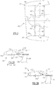
- Figure 3B shows an engine 129, wherein the acoustic treatment 130 extends from an outer end 132 to an inner end 134 as a single unitary item. Outer end 132 extends to forward portion 106. That is, the acoustic treatment 130 spans the connection between the A-flange 110 and the nacelle 112. In this manner, the sound is deadened and reduced. This is particularly beneficial in a short inlet fan and one having droop. It is especially beneficial in an engine having a fan rotor driven through a gear reduction.
- the acoustic treatment 130 can extend entirely around a circumference of a center axis of the engine.
- the actual treatment will not be cylindrical, but will have the contour required for the nacelle's shape.
- Figure 4B shows a potential acoustic treatment composition, wherein outer layers 140 and 142 sandwich a honeycomb material 146. Layer 140 has perforations 147 which face inwardly towards the air flow.
- outer layers 140 and 142 sandwich a honeycomb material 146.
- Layer 140 has perforations 147 which face inwardly towards the air flow.
- other acoustic treatments may come within the scope of this disclosure.
- Figure 5A and 5B are sections along line 5-5 as shown in Figure 4A .
- Figure 5A shows an acoustic treatment 150 having a control 152 supplying current to a heating element 154. This will provide heating along the length of the acoustic treatment 130 to reduce the likelihood of ice accumulation.
- a pipe 162 delivers air into a passage 164 in the acoustic treatment 160 and, then to a plurality of outlets 166 passing air to an inner periphery 168 of the acoustic treatment 160.
- noise may be reduced without increasing the likelihood of ice accumulation such that the short inlet fan with droop does not raise undesirable noise issues.
Landscapes
- Engineering & Computer Science (AREA)
- Mechanical Engineering (AREA)
- General Engineering & Computer Science (AREA)
- Chemical & Material Sciences (AREA)
- Combustion & Propulsion (AREA)
- Structures Of Non-Positive Displacement Pumps (AREA)
Abstract
Description
- This application relates to a gas turbine engine having a noise reduction feature.
- Gas turbine engines are known and typically include a fan delivering air into a bypass duct as propulsion air and into a compressor as core flow. The air is compressed in the compressor and delivered into a combustor where it is mixed with fuel and ignited. Products of this combustion pass downstream over turbine rotors, driving them to rotate.
- Recently, a gear reduction has been incorporated between a fan drive turbine and the fan rotor. This has increased the design freedom for the gas turbine engine designer. In particular, the fan can now be made to rotate slower than the turbine. With this change, the diameter of the fan has increased.
- It has recently been proposed to provide a gas turbine engine, where the inlet or area of a surrounding housing or nacelle forward of the fan rotor, is shorter than in the past. Providing a shorter inlet reduces the weight of the engine and also reduces external drag. Other benefits include reducing a bending moment and corresponding load on an engine structure during flight conditions such as takeoff. Further, by making the inlet shorter, the overall envelope of the engine is reduced.
- However, the shorter inlets raise various challenges. In particular, noise issues are raised.
- In a featured embodiment, a gas turbine engine comprises a fan rotor having fan blades received within an outer nacelle, and the outer nacelle having an inner surface. The outer nacelle is secured to an inner portion through a mount flange at a first axial location. An acoustic treatment extends inwardly of the outer portion of the nacelle and across the axial location of the mount flange and further inwardly toward the fan blades.
- In another embodiment according to the previous embodiment, the acoustic treatment is continuous for 360° about a center axis of the engine.
- In another embodiment according to any of the previous embodiments, a distance is defined from a plane defined by leading edges of the blades to an axial location of a forwardmost part of the nacelle. An outer diameter of the fan blades is defined, and a ratio of the distance to the outer diameter is between about 0.2 and about 0.5.
- In another embodiment according to any of the previous embodiments, the outermost end of the nacelle extends outwardly for varying extents across a circumference of the nacelle, and the ratio of the distance to the outer diameter for all locations of the nacelle is between about 0.2 and about 0.45.
- In another embodiment according to any of the previous embodiments, the ratio is greater than about 0.25.
- In another embodiment according to any of the previous embodiments, the ratio is greater than about 0.30.
- In another embodiment according to any of the previous embodiments, the ratio is less than about 0.40.
- In another embodiment according to any of the previous embodiments, the acoustic treatment includes a honeycomb material.
- In another embodiment according to any of the previous embodiments, a fan drive turbine driving the fan rotor through a gear reduction.
- In another embodiment according to any of the previous embodiments, a gear ratio of the gear reduction is greater than about 2.3.
- In another embodiment according to any of the previous embodiments, a pressure ratio across the fan drive turbine is greater than about 5.
- In another embodiment according to any of the previous embodiments, the fan rotor delivers air into a bypass duct as bypass air, and into a core engine including a compressor, and a bypass ratio is defined as the volume of air being delivered into the bypass duct to the volume of air delivered into the core engine, with the bypass ratio being greater than about 6.
- In another embodiment according to any of the previous embodiments, the acoustic treatment is provided with an anti-icing feature.
- In another embodiment according to any of the previous embodiments, the feature includes an electric heater element.
- In another embodiment according to any of the previous embodiments, the feature system includes the delivery of air to the nacelle.
- In another embodiment according to any of the previous embodiments, the mount flange is an A-flange.
- In another embodiment according to any of the previous embodiments, the fan rotor delivers air into a bypass duct as bypass air, and into a core engine including a compressor. A bypass ratio is defined as the volume of air being delivered into the bypass duct to the volume of air delivered into the core engine, with the bypass ratio being greater than about 6.
- In another embodiment according to any of the previous embodiments, the acoustic treatment is provided with an anti-icing feature.
- In another embodiment according to any of the previous embodiments, the feature includes an electric heater element.
- In another embodiment according to any of the previous embodiments, the feature system includes the delivery of air to the nacelle.
- These and other features may be best understood from the following drawings and specification.
-
-
Figure 1 schematically shows an embodiment of a gas turbine engine. -
Figure 2 shows a challenge in short inlet engines. -
Figure 3A shows a prior art engine. -
Figure 3B shows a first embodiment. -
Figure 4A shows another view of theFigure 3B embodiment. -
Figure 4B is a cross-section of theFigure 3B embodiment. -
Figure 5A is a view along line 5-5 ofFigure 4 . -
Figure 5B shows yet another embodiment along line 5-5 ofFigure 4 . -
Figure 1 schematically illustrates agas turbine engine 20. Thegas turbine engine 20 is disclosed herein as a two-spool turbofan that generally incorporates afan section 22, acompressor section 24, acombustor section 26 and aturbine section 28. Alternative engines might include an augmentor section (not shown) among other systems or features. Thefan section 22 drives air along a bypass flow path B in a bypass duct defined within anacelle 15, while thecompressor section 24 drives air along a core flow path C for compression and communication into thecombustor section 26 then expansion through theturbine section 28. Although depicted as a two-spool turbofan gas turbine engine in the disclosed non-limiting embodiment, it should be understood that the concepts described herein are not limited to use with two-spool turbofans as the teachings may be applied to other types of turbine engines including three-spool architectures. - The
exemplary engine 20 generally includes alow speed spool 30 and ahigh speed spool 32 mounted for rotation about an engine central longitudinal axis A relative to an enginestatic structure 36 viaseveral bearing systems 38. It should be understood thatvarious bearing systems 38 at various locations may alternatively or additionally be provided, and the location ofbearing systems 38 may be varied as appropriate to the application. - The
low speed spool 30 generally includes aninner shaft 40 that interconnects afan 42, a first (or low)pressure compressor 44 and a first (or low)pressure turbine 46. Theinner shaft 40 is connected to thefan 42 through a speed change mechanism, which in exemplarygas turbine engine 20 is illustrated as a gearedarchitecture 48 to drive thefan 42 at a lower speed than thelow speed spool 30. Thehigh speed spool 32 includes anouter shaft 50 that interconnects a second (or high)pressure compressor 52 and a second (or high)pressure turbine 54. Acombustor 56 is arranged inexemplary gas turbine 20 between thehigh pressure compressor 52 and thehigh pressure turbine 54. Amid-turbine frame 57 of the enginestatic structure 36 is arranged generally between thehigh pressure turbine 54 and thelow pressure turbine 46. Themid-turbine frame 57 further supports bearingsystems 38 in theturbine section 28. Theinner shaft 40 and theouter shaft 50 are concentric and rotate viabearing systems 38 about the engine central longitudinal axis A which is collinear with their longitudinal axes. - The core airflow is compressed by the
low pressure compressor 44 then thehigh pressure compressor 52, mixed and burned with fuel in thecombustor 56, then expanded over thehigh pressure turbine 54 andlow pressure turbine 46. Themid-turbine frame 57 includesairfoils 59 which are in the core airflow path C. Theturbines low speed spool 30 andhigh speed spool 32 in response to the expansion. It will be appreciated that each of the positions of thefan section 22,compressor section 24,combustor section 26,turbine section 28, and fandrive gear system 48 may be varied. For example,gear system 48 may be located aft ofcombustor section 26 or even aft ofturbine section 28, andfan section 22 may be positioned forward or aft of the location ofgear system 48. - The
engine 20 in one example is a high-bypass geared aircraft engine. In a further example, theengine 20 bypass ratio is greater than about six, with an example embodiment being greater than about ten, the gearedarchitecture 48 is an epicyclic gear train, such as a planetary gear system or other gear system, with a gear reduction ratio of greater than about 2.3 and thelow pressure turbine 46 has a pressure ratio that is greater than about five. In one disclosed embodiment, theengine 20 bypass ratio is greater than about ten, the fan diameter is significantly larger than that of thelow pressure compressor 44, and thelow pressure turbine 46 has a pressure ratio that is greater than about five.Low pressure turbine 46 pressure ratio is pressure measured prior to inlet oflow pressure turbine 46 as related to the pressure at the outlet of thelow pressure turbine 46 prior to an exhaust nozzle. The gearedarchitecture 48 may be an epicycle gear train, such as a planetary gear system or other gear system, with a gear reduction ratio of greater than about 2.3:1. It should be understood, however, that the above parameters are only exemplary of one embodiment of a geared architecture engine and that the present invention is applicable to other gas turbine engines including direct drive turbofans. - A significant amount of thrust is provided by the bypass flow B due to the high bypass ratio. The
fan section 22 of theengine 20 is designed for a particular flight condition -- typically cruise at about 0.8 Mach and about 35,000 feet (10,668 meters). The flight condition of 0.8 Mach and 35,000 ft (10,668 meters), with the engine at its best fuel consumption - also known as "bucket cruise Thrust Specific Fuel Consumption ('TSFC')" - is the industry standard parameter of lbm of fuel being burned divided by lbf of thrust the engine produces at that minimum point. "Low fan pressure ratio" is the pressure ratio across the fan blade alone, without a Fan Exit Guide Vane ("FEGV") system. The low fan pressure ratio as disclosed herein according to one non-limiting embodiment is less than about 1.45. "Low corrected fan tip speed" is the actual fan tip speed in ft/sec divided by an industry standard temperature correction of [(Tram °R) / (518.7 °R)]0.5 (where °R = K x 9/5). The "Low corrected fan tip speed" as disclosed herein according to one non-limiting embodiment is less than about 1150 ft / second (350.5 meters/second). -
Figure 2 shows an engine known as a short inlet engine. As shown, a nacelle 94 has outermost, or forwardmost ends 96 and 97. As can be seen, the forwardmost ends do not necessarily lie in a common plane perpendicular to a center axis of the engine. Rather, point 96 is further forward thanpoint 97.Fan blades 98 have anouter diameter 99. The nacelle 94 is shown to have a radially inwardly extending innermost point, orthroat 104.Point 104 is inward of theouter diameter 99 of thefan blade 98. As shown schematically, the fan blades have aroot section 101 received in ahub 103 of the fan rotor. - The short inlet may be defined by a distance L measured from: (a) a plane X perpendicular to a central axis C, which plane also being tangent to a leading edge or forward
most point 102 of thefan blade 98 to (b) a plane defined by the forwardmost points (including ends 96, 97) of the nacelle 94. A ratio is defined of L:D with D being the outer diameter of thefan blade 98. - In one embodiment L:D is between about 0.2 and about 0.5 or, more narrowly, about 0.45. Alternatively, the ratio may be greater than about 0.25 and in alternative embodiments greater than about 0.30. In embodiments, the ratio of L:D may be less than about 0.40.
- As can be appreciated, the L:D quantity would be different if measured to the
forwardmost point 96 than to theforwardmost point 97. However, in embodiments the ratio at theforwardmost point 96 would still be less than about 0.45, and the ratio at theshortest point 97 would still be greater than about 0.2. Also, the ratio can be taken as an average L taken to bothpoints - Stated another way, the forwardmost end of said nacelle extends outwardly for varying extents across the circumference of the nacelle, and the ratio of the L:D for all portions of the varying distance of the nacelle being between about 0.2 and about 0.45.
- The engine of
Figure 2 , wherein the ends 96 and 97 are not aligned, could be said to have droop. Such an arrangement has beneficial characteristics. However, it results in the area betweenpoint 97 and theleading edge 102 being very short. This raises challenges with regard to the reduction of noise and, also with distortion of the air approaching thefan blade 98. All of this can result in increased noise emanating from the engine. - As shown in
Figure 3A , aprior art engine 100 had afan blade 95 with a leading edge 105. Anouter end 106 of anacelle 112 was provided with a firstacoustic treatment 108. An A-flange 110 is relied upon to connect theforward portion 106 to arearward mount portion 114 through aconnector 116. In this prior art, a separateacoustic treatment 118 was positioned rearward of theA-flange 110. Agap 120 existed between theacoustic treatments - In engines with the short inlet, as mentioned above, and, in particular, with engines having droop, this noise becomes problematic.
Figure 3B shows anengine 129, wherein theacoustic treatment 130 extends from anouter end 132 to aninner end 134 as a single unitary item.Outer end 132 extends to forwardportion 106. That is, theacoustic treatment 130 spans the connection between the A-flange 110 and thenacelle 112. In this manner, the sound is deadened and reduced. This is particularly beneficial in a short inlet fan and one having droop. It is especially beneficial in an engine having a fan rotor driven through a gear reduction. - As shown in
Figure 4A , theacoustic treatment 130 can extend entirely around a circumference of a center axis of the engine. Of course, the actual treatment will not be cylindrical, but will have the contour required for the nacelle's shape. -
Figure 4B shows a potential acoustic treatment composition, whereinouter layers honeycomb material 146.Layer 140 hasperforations 147 which face inwardly towards the air flow. Of course, other acoustic treatments may come within the scope of this disclosure. -
Figure 5A and 5B are sections along line 5-5 as shown inFigure 4A . There are challenges with regard to the development of ice and, in particular, in short inlet engines and those having droop. -
Figure 5A shows anacoustic treatment 150 having acontrol 152 supplying current to aheating element 154. This will provide heating along the length of theacoustic treatment 130 to reduce the likelihood of ice accumulation. - In an alternative 160, as shown in
Figure 5B , apipe 162 delivers air into apassage 164 in theacoustic treatment 160 and, then to a plurality ofoutlets 166 passing air to aninner periphery 168 of theacoustic treatment 160. - By providing a one piece acoustic treatment that incorporates anti-ice features, noise may be reduced without increasing the likelihood of ice accumulation such that the short inlet fan with droop does not raise undesirable noise issues.
- Although various embodiments of this invention have been disclosed, a worker of ordinary skill in this art would recognize that certain modifications would come within the scope of this invention. For that reason, the following claims should be studied to determine the true scope and content of this invention.
Claims (15)
- A gas turbine engine (20) comprising:a fan rotor having fan blades (98) received within an outer nacelle (112), said outer nacelle (112) having an inner surface, and said outer nacelle (112) secured to an inner portion (114) through a mount flange (110) at a first axial location; andan acoustic treatment (130) extending inwardly of an outer portion (106) of said outer nacelle (112) and across the axial location of the mount flange (110) and further inwardly toward said fan blades (98).
- The gas turbine engine (20) as set forth in claim 1, wherein said acoustic treatment (130) is continuous for 360° about a center axis (C) of the engine (20).
- The gas turbine engine (20) as set forth in claim 1 or 2, wherein a distance (L) is defined from a plane (102) defined by leading edges (105) of said blades (98) to an axial location of a forwardmost part (96, 97) of said nacelle, and an outer diameter (D) of said fan blades (98) being defined, and a ratio of said distance (L) to said outer diameter (D) is between 0.2 and 0.5.
- The gas turbine engine (20) as set forth in claim 3, wherein said forwardmost part (96, 97) of said nacelle (112) extends outwardly for varying extents across a circumference of said nacelle, and said ratio of said distance (L) to the outer diameter (D) for all locations of said nacelle (112) being between 0.2 and 0.45.
- The gas turbine engine (20) as set forth in claim 3 or 4, wherein said ratio is greater than 0.25, optionally wherein said ratio is greater than 0.30.
- The gas turbine engine (20) as set forth in any of claims 3 to 5, wherein said ratio is less than 0.40.
- The gas turbine engine (20) as set forth in any preceding claim, wherein said acoustic treatment (130) includes a honeycomb material.
- The gas turbine engine (20) as set forth in any preceding claim, wherein a fan drive turbine (46) drives said fan rotor through a gear reduction (48).
- The gas turbine engine (20) as set forth in claim 8, wherein a gear ratio of said gear reduction (48) is greater than 2.3.
- The gas turbine engine (20) as set forth in claim 8 or 9, wherein a pressure ratio across said fan drive turbine (46) is greater than 5.
- The gas turbine engine (20) as set forth in any preceding claim, wherein said fan rotor delivering air into a bypass duct as bypass air, and into a core engine including a compressor, and a bypass ratio is defined as the volume of air being delivered into said bypass duct to the volume of air delivered into said core engine, with said bypass ratio being greater than about 6.
- The gas turbine engine (20) as set forth in any preceding claim, wherein said acoustic treatment (130) is provided with an anti-icing feature.
- The gas turbine engine as set forth in claim 12, wherein said feature includes an electric heater element.
- The gas turbine engine as set forth in claim 12 or 13 wherein said feature system includes the delivery of air to said nacelle (112).
- The gas turbine engine as set forth in any preceding claim, wherein said mount flange (110) is an A-flange.
Applications Claiming Priority (1)
| Application Number | Priority Date | Filing Date | Title |
|---|---|---|---|
| US14/974,220 US10794398B2 (en) | 2015-12-18 | 2015-12-18 | Gas turbine engine with one piece acoustic treatment |
Publications (1)
| Publication Number | Publication Date |
|---|---|
| EP3181864A1 true EP3181864A1 (en) | 2017-06-21 |
Family
ID=57681322
Family Applications (1)
| Application Number | Title | Priority Date | Filing Date |
|---|---|---|---|
| EP16205173.4A Withdrawn EP3181864A1 (en) | 2015-12-18 | 2016-12-19 | Gas turbine engine with one piece acoustic treatment |
Country Status (2)
| Country | Link |
|---|---|
| US (1) | US10794398B2 (en) |
| EP (1) | EP3181864A1 (en) |
Cited By (1)
| Publication number | Priority date | Publication date | Assignee | Title |
|---|---|---|---|---|
| FR3085437A1 (en) * | 2018-09-05 | 2020-03-06 | Airbus Operations | AIR INTAKE STRUCTURE OF AN AIRCRAFT NACELLE |
Citations (4)
| Publication number | Priority date | Publication date | Assignee | Title |
|---|---|---|---|---|
| US20130283821A1 (en) * | 2012-04-30 | 2013-10-31 | Jonathan Gilson | Gas turbine engine and nacelle noise attenuation structure |
| US20140064927A1 (en) * | 2009-04-14 | 2014-03-06 | Rohr, Inc. | Inlet section of an aircraft engine nacelle |
| US20150023780A1 (en) * | 2013-07-16 | 2015-01-22 | United Technologies Corporation | Liner attaching scheme |
| US20150044028A1 (en) * | 2012-12-20 | 2015-02-12 | United Technologies Corporation | Low pressure ratio fan engine having a dimensional relationship between inlet and fan size |
Family Cites Families (8)
| Publication number | Priority date | Publication date | Assignee | Title |
|---|---|---|---|---|
| US5498127A (en) * | 1994-11-14 | 1996-03-12 | General Electric Company | Active acoustic liner |
| US7837150B2 (en) * | 2007-12-21 | 2010-11-23 | Rohr, Inc. | Ice protection system for a multi-segment aircraft component |
| BRPI0916330A2 (en) * | 2008-07-30 | 2018-06-12 | Aircelle Sa | acoustic attenuation panel for an aircraft engine nacelle, air intake structure, internal fixed structure |
| EP2321510B1 (en) * | 2008-07-30 | 2013-07-03 | Aircelle | Air intake structure of a turbojet engine nacelle with pneumatic anti-icing |
| FR2943726B1 (en) | 2009-03-31 | 2014-04-25 | Snecma | ROTATING INPUT COVER FOR TURBOMACHINE, COMPRISING AN EXTREMITY BEFORE EXCENTREE |
| DE102011080077A1 (en) * | 2011-07-29 | 2013-01-31 | Siemens Aktiengesellschaft | Method for detecting the true coincidence of two charge pulses on adjacent pixel elements, X-ray detector and X-ray image acquisition device |
| US8690097B1 (en) | 2012-04-30 | 2014-04-08 | The Boeing Company | Variable-geometry rotating spiral cone engine inlet compression system and method |
| US11480104B2 (en) | 2013-03-04 | 2022-10-25 | Raytheon Technologies Corporation | Gas turbine engine inlet |
-
2015
- 2015-12-18 US US14/974,220 patent/US10794398B2/en active Active
-
2016
- 2016-12-19 EP EP16205173.4A patent/EP3181864A1/en not_active Withdrawn
Patent Citations (4)
| Publication number | Priority date | Publication date | Assignee | Title |
|---|---|---|---|---|
| US20140064927A1 (en) * | 2009-04-14 | 2014-03-06 | Rohr, Inc. | Inlet section of an aircraft engine nacelle |
| US20130283821A1 (en) * | 2012-04-30 | 2013-10-31 | Jonathan Gilson | Gas turbine engine and nacelle noise attenuation structure |
| US20150044028A1 (en) * | 2012-12-20 | 2015-02-12 | United Technologies Corporation | Low pressure ratio fan engine having a dimensional relationship between inlet and fan size |
| US20150023780A1 (en) * | 2013-07-16 | 2015-01-22 | United Technologies Corporation | Liner attaching scheme |
Cited By (3)
| Publication number | Priority date | Publication date | Assignee | Title |
|---|---|---|---|---|
| FR3085437A1 (en) * | 2018-09-05 | 2020-03-06 | Airbus Operations | AIR INTAKE STRUCTURE OF AN AIRCRAFT NACELLE |
| EP3620631A1 (en) * | 2018-09-05 | 2020-03-11 | Airbus Operations (S.A.S.) | Air intake structure for an aircraft nacelle |
| US11427343B2 (en) | 2018-09-05 | 2022-08-30 | Airbus Operations (S.A.S.) | Air intake structure of an aircraft nacelle |
Also Published As
| Publication number | Publication date |
|---|---|
| US20170175775A1 (en) | 2017-06-22 |
| US10794398B2 (en) | 2020-10-06 |
Similar Documents
| Publication | Publication Date | Title |
|---|---|---|
| EP3933181A1 (en) | High thrust geared gas turbine engine | |
| US20190178094A1 (en) | Integrally bladed rotor | |
| US20190024673A1 (en) | Integrally bladed rotor having double fillet | |
| US9909429B2 (en) | Lightweight blade for gas turbine engine | |
| US10294871B2 (en) | Exhaust nozzle arrangement for geared turbofan | |
| US11391205B2 (en) | Anti-icing core inlet stator assembly for a gas turbine engine | |
| EP3045663B1 (en) | Integrally bladed fan rotor with pressure side thickness on blade traing edge | |
| US11111801B2 (en) | Turbine vane with platform pad | |
| EP3181865B1 (en) | Gas turbine engine | |
| US10794398B2 (en) | Gas turbine engine with one piece acoustic treatment | |
| US10227884B2 (en) | Fan platform with leading edge tab | |
| EP3181863B1 (en) | Gas turbine engine with minimized inlet distortion | |
| EP3181862B1 (en) | Gas turbine engine with rotating inlet | |
| US10731661B2 (en) | Gas turbine engine with short inlet and blade removal feature | |
| EP2955325B1 (en) | Geared turbofan with integrally bladed rotor |
Legal Events
| Date | Code | Title | Description |
|---|---|---|---|
| PUAI | Public reference made under article 153(3) epc to a published international application that has entered the european phase |
Free format text: ORIGINAL CODE: 0009012 |
|
| STAA | Information on the status of an ep patent application or granted ep patent |
Free format text: STATUS: THE APPLICATION HAS BEEN PUBLISHED |
|
| AK | Designated contracting states |
Kind code of ref document: A1 Designated state(s): AL AT BE BG CH CY CZ DE DK EE ES FI FR GB GR HR HU IE IS IT LI LT LU LV MC MK MT NL NO PL PT RO RS SE SI SK SM TR |
|
| AX | Request for extension of the european patent |
Extension state: BA ME |
|
| STAA | Information on the status of an ep patent application or granted ep patent |
Free format text: STATUS: REQUEST FOR EXAMINATION WAS MADE |
|
| 17P | Request for examination filed |
Effective date: 20171221 |
|
| RBV | Designated contracting states (corrected) |
Designated state(s): AL AT BE BG CH CY CZ DE DK EE ES FI FR GB GR HR HU IE IS IT LI LT LU LV MC MK MT NL NO PL PT RO RS SE SI SK SM TR |
|
| STAA | Information on the status of an ep patent application or granted ep patent |
Free format text: STATUS: EXAMINATION IS IN PROGRESS |
|
| 17Q | First examination report despatched |
Effective date: 20190513 |
|
| GRAP | Despatch of communication of intention to grant a patent |
Free format text: ORIGINAL CODE: EPIDOSNIGR1 |
|
| STAA | Information on the status of an ep patent application or granted ep patent |
Free format text: STATUS: GRANT OF PATENT IS INTENDED |
|
| INTG | Intention to grant announced |
Effective date: 20200703 |
|
| STAA | Information on the status of an ep patent application or granted ep patent |
Free format text: STATUS: THE APPLICATION IS DEEMED TO BE WITHDRAWN |
|
| RAP1 | Party data changed (applicant data changed or rights of an application transferred) |
Owner name: RAYTHEON TECHNOLOGIES CORPORATION |
|
| 18D | Application deemed to be withdrawn |
Effective date: 20201114 |