EP3181443A1 - Fuselage structure for accomodating tails and canards of different sizes and shapes - Google Patents
Fuselage structure for accomodating tails and canards of different sizes and shapes Download PDFInfo
- Publication number
- EP3181443A1 EP3181443A1 EP16190299.4A EP16190299A EP3181443A1 EP 3181443 A1 EP3181443 A1 EP 3181443A1 EP 16190299 A EP16190299 A EP 16190299A EP 3181443 A1 EP3181443 A1 EP 3181443A1
- Authority
- EP
- European Patent Office
- Prior art keywords
- horizontal
- canard
- vertical
- structural interface
- spar
- Prior art date
- Legal status (The legal status is an assumption and is not a legal conclusion. Google has not performed a legal analysis and makes no representation as to the accuracy of the status listed.)
- Granted
Links
Images

Classifications
-
- B—PERFORMING OPERATIONS; TRANSPORTING
- B64—AIRCRAFT; AVIATION; COSMONAUTICS
- B64C—AEROPLANES; HELICOPTERS
- B64C1/00—Fuselages; Constructional features common to fuselages, wings, stabilising surfaces or the like
- B64C1/26—Attaching the wing or tail units or stabilising surfaces
-
- B—PERFORMING OPERATIONS; TRANSPORTING
- B64—AIRCRAFT; AVIATION; COSMONAUTICS
- B64C—AEROPLANES; HELICOPTERS
- B64C3/00—Wings
- B64C3/18—Spars; Ribs; Stringers
- B64C3/185—Spars
-
- B—PERFORMING OPERATIONS; TRANSPORTING
- B64—AIRCRAFT; AVIATION; COSMONAUTICS
- B64C—AEROPLANES; HELICOPTERS
- B64C39/00—Aircraft not otherwise provided for
- B64C39/12—Canard-type aircraft
-
- B—PERFORMING OPERATIONS; TRANSPORTING
- B64—AIRCRAFT; AVIATION; COSMONAUTICS
- B64C—AEROPLANES; HELICOPTERS
- B64C5/00—Stabilising surfaces
- B64C5/02—Tailplanes
-
- B—PERFORMING OPERATIONS; TRANSPORTING
- B64—AIRCRAFT; AVIATION; COSMONAUTICS
- B64C—AEROPLANES; HELICOPTERS
- B64C5/00—Stabilising surfaces
- B64C5/04—Noseplanes
-
- B—PERFORMING OPERATIONS; TRANSPORTING
- B64—AIRCRAFT; AVIATION; COSMONAUTICS
- B64C—AEROPLANES; HELICOPTERS
- B64C5/00—Stabilising surfaces
- B64C5/06—Fins
-
- B—PERFORMING OPERATIONS; TRANSPORTING
- B64—AIRCRAFT; AVIATION; COSMONAUTICS
- B64C—AEROPLANES; HELICOPTERS
- B64C2211/00—Modular constructions of airplanes or helicopters
Definitions
- This disclosure relates generally airplanes having fuselage structures that can accommodate vertical tails, horizontal tails and canards of different structural configurations.
- the aft portion of an aircraft fuselage includes structural interfaces for connecting the aft portion to a vertical tail and/or to a horizontal tail.
- the vertical tail and the horizontal tail each include a front spar and a rear spar.
- the aft end of the fuselage will include four structural interfaces, including two structural interfaces for connection to the front and rear spars of the vertical tail and two structural interfaces for connection to the front and rear spars of the horizontal tail.
- the structural interfaces that connect the vertical tail to the fuselage are typically disposed along the top or crown of the fuselage.
- the horizontal tail typically passes through the aft end of the fuselage and the interface used to connect the front spar of the horizontal tail to the fuselage is disposed along the centerline of the fuselage, typically at the jackscrew or the device used to adjust the trim of the horizontal tail.
- the structural interface used to connect the rear spar of the horizontal tail to the fuselage is typically located at the side of body (SOB) of the fuselage in alignment with the pivot point or pivot interface, which connects to both sides (left and right) of the horizontal tail.
- the forward portion of an aircraft fuselage may include structural interfaces for connecting the forward portion to a canard.
- the canard includes a front spar and a rear spar.
- the forward portion of the fuselage will include two structural interfaces (one per side, left and right) for connection to the front and rear spars of the canard.
- the structural interfaces that connect the canard to the fuselage are typically located at the side of body (SOB) of the fuselage.
- the aft end of the fuselage must undergo significant modifications or redesign to accommodate a different vertical tail and/or a different horizontal tail.
- the canard such as the size, shape, or sweep angle(s) of the canard
- the forward end of the fuselage must undergo significant modifications or redesign to accommodate a different canard.
- An aircraft which comprises a fuselage that comprises an aft portion.
- the aft portion comprises at least one front vertical structural interface and at least one rear vertical structural interface.
- the at least one front vertical structural interface is connected to a front spar of a first vertical tail or to a front spar of a second vertical tail.
- the at least one rear vertical structural interface is connected to a rear spar of the first vertical tail or to a rear spar of the second vertical tail.
- the first and second vertical tails are of different sizes.
- Another aircraft which also comprises a fuselage that comprises an aft portion.
- the fuselage is defined by a centerline that extends through the fuselage and a side of body (SOB) that surrounds the centerline.
- the aft portion includes at least one front horizontal structural interface and at least one rear horizontal structural interface.
- the at least one front horizontal structural interface is disposed along the centerline and the at least one rear horizontal structural interface is disposed at the SOB.
- the at least one front horizontal structural interface is connected to a front spar of a first horizontal tail or to a front spar of a second horizontal tail.
- the at least one rear horizontal structural interface is connected to a rear spar of the first horizontal tail or to a rear spar of the second horizontal tail.
- the first and second horizontal tails are of different sizes.
- Another aircraft which comprises a fuselage that comprises a forward portion.
- the fuselage is defined by a centerline that extends through the fuselage and a side of body (SOB) that surrounds the centerline.
- the forward portion includes at least one front canard structural interface and at least one rear canard structural interface.
- the at least one front canard structural interface is connected to a front spar of a first canard or to a front spar of a second canard.
- the at least one rear canard structural interface is connected to a rear spar of the first canard or to a rear spar of the second canard.
- the first and second canards are of different sizes.
- a method of enhancing an aircraft wherein the aircraft has a fuselage with an aft portion and a forward portion.
- the aircraft also includes one or more of a vertical tail, a horizontal tail and a canard.
- the method comprises, wherein if the aircraft has a vertical tail, providing the aft portion of the fuselage with at least one front vertical structural interface and at least one rear vertical structural interface, and wherein if the aircraft has a horizontal tail, providing the aft portion of the fuselage with at least one front horizontal structural interface and at least one rear horizontal structural interface, and wherein if the aircraft has a canard, providing the forward portion of the fuselage with at least one front canard structural interface and at least one rear canard structural interface.
- the method further comprises making at least one enhancement to the aircraft selected from the group consisting of:
- the invention can involve an aircraft that may include a fuselage comprising an aft portion, the aft portion including at least one front vertical structural interface and at least one rear vertical structural interface, the at least one front vertical structural interface connected to a front spar of a first vertical tail or to a front spar of a second vertical tail, the at least one rear vertical structural interface connected to a rear spar of a first vertical tail or to a rear spar of a second vertical tail, wherein the first and second vertical tails are of different sizes.
- the front spars of the first and second vertical tails may each define a sweep angle
- the rear spars of the first and second vertical tails may each define a sweep angle
- the first and second vertical tails each have a leading edge that defines a sweep angle
- the first and second vertical tails each have at least one trailing edge that defines a sweep angle
- the first and second vertical tails each have a vertical box chord
- the first and second vertical tails each have a vertical root chord
- the first and second vertical tails have at least one structural difference selected from the group consisting of different sweep angles of the front spars, different sweep angles of the rear spars, different sweep angles of the leading edges, different sweep angles of the trailing edges, different vertical box chords, and different vertical root chords.
- the front spar of the first vertical tail may be connected to a first front vertical structural interface and the front spar of the second vertical tail is connected to a second front vertical structural interface, the first front vertical structural interface being different from the second front vertical structural interface.
- the rear spar of the first vertical tail may be connected to a first rear vertical structural interface and the rear spar of the second vertical tail may be connected to a second rear vertical structural interface, the first rear vertical structural interface being different from the second rear vertical structural interface. This can enhance performance of the aerodynamics and improve structural reliability.
- the aft portion of the fuselage may include at least one front horizontal structural interface and at least one rear horizontal structural interface, the at least one front horizontal structural interface connected to a front spar of a first horizontal tail or to a front spar of a second horizontal tail, the at least one rear horizontal structural interface connected to a rear spar of the first horizontal tail or to a rear spar of the second horizontal tail, therein the front spars of the first and second horizontal tails each define a sweep angle, the rear spars of the first and second horizontal tails each define a sweep angle, the first and second horizontal tails each have a leading edge that defines a sweep angle, the first and second horizontal tails each have at least one trailing edge that each defines a sweep angle, the first and second horizontal tails each have a horizontal box chord, the first and second horizontal tails each have a horizontal root chord, and the first and second horizontal tails each have a size, wherein the first and second horizontal tails have at least one structural difference selected from the group consisting of different sweep angles of the front spars, different sweep angles of
- the front spar of the first horizontal tail may be connected to a first front horizontal structural interface and the front spar of the second horizontal tail is connected to a second front horizontal structural interface, the first front horizontal structural interface being different from the second front horizontal structural interface.
- the rear spar of the first horizontal tail may be connected to a first rear horizontal structural interface and the rear spar of the second horizontal tail is connected to a second rear horizontal structural interface, the first rear horizontal structural interface being different from the second rear horizontal structural interface.
- the fuselage further may include a forward portion, the forward portion including at least one front canard structural interface and at least one rear canard structural interface, the at least one front canard structural interface connected to a front spar of a first canard or to a front spar of a second canard, the at least one rear canard structural interface connected to a rear spar of the first canard or to a rear spar of the second canard, wherein the front spars of the first and second canards each define a sweep angle, the rear spars of the first and second canards each define a sweep angle, the first and second canards each have a leading edge that defines a sweep angle, the first and second canards each have at least one trailing edge that each defines a sweep angle, the first and second canards each have a canard box chord, the first and second canards each have a canard root chord, and the first and second canards each have a size, wherein the first and second canards have at least one structural difference selected from the group consisting of different sweep angles of
- the front spar of the first canard may be connected to a first front canard structural interface and the front spar of the second canard is connected to a second front canard structural interface, the first front canard structural interface being different from the second front canard structural interface.
- the rear spar of the first canard may be connected to a first rear canard structural interface and the rear spar of the second canard is connected to a second rear canard structural interface, the first rear canard structural interface being different from the second rear canard structural interface.
- the invention can involve an aircraft that may include a fuselage comprising an aft portion, the aft portion including at least one front horizontal structural interface and at least one rear horizontal structural interface, the at least one front horizontal structural interface connected to a front spar of a first horizontal tail or to a front spar of a second horizontal tail, the at least one rear horizontal structural interface connected to a rear spar of the first horizontal tail or to a rear spar of the second horizontal tail, wherein the first and second horizontal tails are of different sizes.
- the front spars of the first and second horizontal tails each may define a sweep angle
- the rear spars of the first and second horizontal tails each may define a sweep angle
- the first and second horizontal tails each have a leading edge that defines a sweep angle
- the first and second horizontal tails each have at least one trailing edge that each defines a sweep angle
- the first and second horizontal tails each have a horizontal box chord
- the first and second horizontal tails each have a horizontal root chord
- the first and second horizontal tails have at least one structural difference selected from the group consisting of different sweep angles of the front spars, different sweep angles of the rear spars, different sweep angles of the leading edges, different sweep angles of the trailing edges, different horizontal box chords, and/or different horizontal root chords.
- the front spar of the first horizontal tail is connected to a first front horizontal structural interface and the front spar of the second horizontal tail is connected to a second front horizontal structural interface, the first front horizontal structural interface being different from the second front horizontal structural interface.
- the rear spar of the first horizontal tail is connected to a first rear horizontal structural interface and the rear spar of the second horizontal tail is connected to a second rear horizontal structural interface, the first rear horizontal structural interface being different from the second rear horizontal structural interface.
- the aft portion of the fuselage includes at least one front vertical structural interface and at least one rear vertical structural interface,
- the at least one front vertical structural interface connected to a front spar of a first vertical tail or to a front spar of a second vertical tail
- the at least one rear vertical structural interface connected to a rear spar of the first vertical tail or to a rear spar of the second vertical tail
- the front spars of first and second vertical tails each define a sweep angle
- the rear spars of the first and second vertical tails each define a sweep angle
- the first and second vertical tails each have a leading edge that defines a sweep angle
- the first and second vertical tails each have at least one trailing edge that each defines a sweep angle
- the first and second vertical tails each have a vertical box chord
- the first and second vertical tails each have a vertical root chord
- the first and second vertical tails each have a size
- the first and second vertical tails have at least one structural difference selected from the group consisting of different sweep angles of the front spars,
- the fuselage may further comprise a forward portion that includes at least one front canard structural interface and at least one rear canard structural interface, the at least one front canard structural interface connected to a front spar of a first canard or to a front spar of a second canard, the at least one rear canard structural interface connected to a rear spar of the first canard or to a rear spar of the second canard, wherein the front spars of the first and second canards each define a sweep angle, the rear spars of the first and second canards each define a sweep angle, the first and second canards each have a leading edge that defines a sweep angle, the first and second canards each have at least one trailing edge that each defines a sweep angle, the first and second canards each have a canard box chord, the first and second canards each have a canard root chord, the first and second canards each have a size, wherein the first and second canards have at least one structural difference selected from the group consisting of different sweep angles of the front spars
- the invention can involve an aircraft that may include a fuselage comprising a forward portion that includes at least one front canard structural interface and at least one rear canard structural interface, the at least one front canard structural interface connected to a front spar of a first canard or to a front spar of a second canard, the at least one rear canard structural interface connected to a rear spar of the first canard or to a rear spar of the second canard, wherein the first and second canards are of different sizes.
- the front spars of first and second canards each may define a sweep angle
- the rear spars of the first and second canards each may define a sweep angle
- the first and second canards each may have a leading edge that defines a sweep angle
- the first and second canards each may have at least one trailing edge that each defines a sweep angle
- the first and second canards each have a canard box chord
- the first and second canards each have a horizontal root chord
- the first and second canards may have at least one structural difference selected from the group consisting of different sweep angles of the front spars, different sweep angles of the rear spars, different sweep angles of the leading edges, different sweep angles of the trailing edges, different canard box chords, and/or different canard root chords.
- the front spar of the first canard may be connected to a first front canard structural interface and the front spar of the second canard is connected to a second front canard structural interface, the first front canard structural interface being different from the second front canard structural interface.
- the rear spar of the first canard may be connected to a first rear canard structural interface and the rear spar of the second canard is connected to a second rear canard structural interface, the first rear canard structural interface being different from the second rear canard structural interface.
- the fuselage may further comprise an aft portion that includes at least one front vertical structural interface and at least one rear vertical structural interface, the at least one front vertical structural interface connected to a front spar of a first vertical tail or to a front spar of a second vertical tail, the at least one rear vertical structural interface connected to a rear spar of the first vertical tail or to a rear spar of the second vertical tail, wherein the front spars of the first and second vertical tails each define a sweep angle, the rear spars of the first and second vertical tails each define a sweep angle, the first and second vertical tails each have a leading edge that defines a sweep angle, the first and second vertical tails each have at least one trailing edge that each defines a sweep angle, the first and second vertical tails each have a vertical box chord, the first and second vertical tails each have a vertical root chord, the first and second vertical tails each have a size, wherein the first and second vertical tails have at least one structural difference selected from the group consisting of different sweep angles of the front spars, different sweep angles
- the fuselage may further comprises an aft portion that includes at least one front horizontal structural interface and at least one rear horizontal structural interface, the at least one front horizontal structural interface connected to a front spar of a first horizontal tail or to a front spar of a second horizontal tail, the at least one rear horizontal structural interface connected to a rear spar of the first horizontal tail or to a rear spar of the second horizontal tail, wherein the front spars of the first and second horizontal tails each define a sweep angle, the rear spars of the first and second horizontal tails each define a sweep angle, the first and second horizontal tails each have a leading edge that defines a sweep angle, the first and second horizontal tails each have at least one trailing edge that each defines a sweep angle, the first and second horizontal tails each have a horizontal box chord, the first and second horizontal tails each have a horizontal root chord, and the first and second horizontal tails each have a size, wherein the first and second horizontal tails have at least one structural difference selected from the group consisting of different sweep angles of the front spars, different sweep
- the invention can involve a method of enhancing an aircraft that may include a fuselage with an aft portion and a forward portion, the aircraft including one or more of a vertical tail, a horizontal tail and a canard, the method comprising: wherein if the aircraft has a vertical tail, providing the aft portion of the fuselage with at least one front vertical structural interface and at least one rear vertical structural interface, wherein if the aircraft has a horizontal tail, providing the aft portion of the fuselage with at least one front horizontal structural interface and at least one rear horizontal structural interface, wherein if the aircraft has a canard, providing the forward portion of the fuselage with at least one front canard structural interface and at least one rear canard structural interface, the method further comprising making at least one enhancement to the aircraft selected from the group consisting of: allowing the at least one front vertical structural interface to connect to a front spar of a first vertical tail and allowing the at least one rear vertical structural interface to connect to a rear spar of the first vertical tail or, in the alternative, allowing the
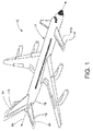
- FIGS. 1-3 illustrate an aircraft 10 that is capable of connection to different vertical tails 13, 14 and/or different horizontal tails 15, 16 and/or different canards 113, 113a, 114, 114a.
- the vertical tails 13, 14, the horizontal tails 15, 16 and the canards 113, 113a, 114, 114a may all differ in size and/or shape and/or sweep angles and/or box chords and/or root chords.
- the term "different size” shall not include adding a simple tip extension to either a vertical tail 13, 14, a horizontal tail 15, 16 or a canard 113, 113a, 114, 114a.
- a different size for a vertical tail 13, 14, horizontal tail 15, 16, or canard 113, 113a, 114, 114a cannot be accomplished for the purposes of this application by extending the existing leading edge and trailing edge lines to a different span, with no changes to the root chord, box chord, or leading/trailing edge sweep angles.
- root chord means the distance from the leading edge to the trailing edge at the fuselage interface and the term “box chord” means the distance from the front spar to the rear spar at the fuselage interface.
- vertical tails typically include a rudder and horizontal tails and canards typically include an elevator.
- the trailing edges of the rudders and elevators are referred to as "movable trailing edges” and the trailing edge of the main structure of a vertical tail, horizontal tail and canard is referred to as a "fixed trailing edge.”
- some tails or canards may not have a rudder or elevator and therefore only one trailing edge, which moves or pivots with the rest of the structure. Therefore, the term trailing edge without the fixed or movable modifiers refers to both fixed and movable trailing edges.
- the aircraft 10 includes a fuselage 17 having an aft portion 18 and a forward portion 118.
- the fuselage 17 may include a crown 20 that extends along the top of the fuselage 17 as shown in FIG. 2 .
- the fuselage 17 may also include a centerline 19 that extends through the fuselage 17 and a side of body (SOB) 21 that surrounds the centerline 19 as shown in FIG. 3 .
- the aft portion 18 of the fuselage 17 may include a plurality of structural interfaces for connecting the aft portion 18 to one of a variety of vertical tails 13, 14 and/or for connecting the aft portion 18 to one of a variety of horizontal tails 15, 16.
- the forward portion 118 may include a plurality of structural interfaces for connecting the forward portion 118 to a variety of canards 113, 113a, 114, 114a.
- the versatility provided by the aft and forward portions 18, 118 of the fuselage 17 enables aircraft designers to change vertical tails 13, 14, horizontal tails 15, 16 and/or canards 113, 113a, 114, 114a without a costly redesign of the structural layout of the aft and/or forward portions 18, 118 of the fuselage 17.
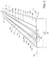
- FIG. 2 illustrates two vertical tails 13, 14 that may be used with the aircraft 10.
- the first vertical tail 13 is illustrated in phantom lines and with three possible front spars 27a, 27b, 27c and three possible rear spars 29a, 29b, 29c.
- the second vertical tail 14 includes just a single front spar 28 and a single rear spar 31. As shown in FIG. 2 , the vertical tails 13, 14 do not need to have a common box chord, a common root chord, or a common tip chord.
- the aft portion 18 of the fuselage 17 comprises at least one front vertical structural interface 22a, 22b, 22c and at least one rear vertical structural interface 23a, 23b, 23c.
- FIG. 2 three front vertical structural interfaces 22a, 22b, 22c are shown because the first vertical tail 13 is illustrated with three possible front spars 27a, 27b, 27c. Further, the front spar 28 of the second vertical tail 14, while meeting the front spar 27c at the front vertical structural interface 22c, does not need to be in alignment with the front spar 27c of the first vertical tail 13. In the example shown, even though the front spar 27c is not in alignment with the front spar 28, only one front vertical structural interface 22c is needed to accommodate both of these design choices.
- FIG. 2 three rear vertical structural interfaces 23a, 23b, 23c are shown because the first vertical tail 13 includes three possible rear spars 29a, 29b, 29c, and the rear spar 29c of the first vertical tail 13 shares a rear vertical structural interface 23c with the rear spar 31 of the second vertical tail 14 even though the rear spar 29c is not in alignment with the rear spar 31.
- the at least one front vertical structural interface 22a, 22b, 22c connects to a front spar 27a, 27b, 27c of the first vertical tail 13 or to the front spar 28 of the second vertical tail 14.
- the at least one rear vertical structural interface 23a, 23b, 23c connects to a rear spar 29a, 29b, 29c of the first vertical tail 13 or to the rear spar 31 of the second vertical tail 14.
- the first and second vertical tails 13, 14 are of different sizes, however, the first and second vertical tails 13, 14 may also differ in other ways as well.
- first and second vertical tails 13, 14 each define a sweep angle
- the rear spars 29a, 29b, 29c, 31 of the first and second vertical tails 13, 14 also each define a sweep angle
- the first and second vertical tails 13, 14 each have a leading edge 32, 33 that defines a sweep angle
- the first and second vertical tails 13, 14 each have a movable trailing edge 25, 26 that defines a sweep angle
- the first and second vertical tails 13, 14 each have a fixed trailing edge 34, 35 that defines a sweep angle
- the first and second vertical tails 13, 14 each include a vertical box chord 24a, 24 that may or may not be the same.
- the first and second vertical tails 13, 14 may have at least one structural difference selected from the group consisting of different sweep angles of the front spars 27a, 27b, 27c, 28, different sweep angles of the rear spars 29a, 29b, 29c, 31, different sweep angles of the leading edges 32, 33, different sweep angles of the movable trailing edges 25, 26, different sweep angles of the fixed trailing edges 34, 35, different vertical box chords 24a, 24, and/or different vertical root chords 224a, 224
- the front and rear vertical structural interfaces 22a, 22b, 22c, 23a, 23b, 23c may be disposed at or along the crown 20 of the fuselage 17. Further, the front and rear vertical structural interfaces 22c, 23c may be separated by a vertical box chord 24 that may be common to both the first and second vertical tails 13, 14. While not required, the use of a common vertical box chord 24 for each vertical tail 13, 14 may reduce the number of structural interfaces required thereby reducing costs. Each vertical tail 13, 14 also may include a rudder 225, 226.
- the rear vertical structural interfaces 23a, 23b, 23c may be connected to a bulkhead 36 for purposes of strength and structural integrity.
- the first and second vertical tails 13, 14 have different sweep angles for at least the front spars 27a, 27b, 27c, 28 and the rear spars 29a, 29b, 29c, 31, which illustrate the versatility of the disclosed embodiments.
- the first and second vertical tails 13, 14 each have a leading edge 32, 33 that defines a sweep angle, and the sweep angle of the leading edge 32 of the first vertical tail 13 is different from the sweep angle of the leading edge 33 of the second vertical tail 14.
- first and second vertical tails 13, 14 each have a movable trailing edge 25, 26 that defines a sweep angle, and the sweep angle of the movable trailing edge 25 of the first vertical tail 13 is different from the sweep angle of the movable trailing edge 26 of the second vertical tail 14.
- first and second vertical tails 13, 14 each have a fixed trailing edge 34, 35 that defines a sweep angle, and the sweep angle of the fixed trailing edge 34 of the first vertical tail 13 is different from the sweep angle of the fixed trailing edge 35 of the second vertical tail 14.
- the aft portion 18 of the fuselage 17 is versatile and enables an aircraft designer to inexpensively provide a family of aircraft 10, each family member having a fuselage 17 with a common aft portion 18 that may accommodate vertical tails 13, 14 of different sizes that may also have different sweep angles at the leading edges 32, 33, different sweep angles at the movable trailing edges 25, 26, different sweep angles at the fixed trailing edges 34, 35, different sweep angles at the front spars 27a, 27b, 27c, 28 different sweep angles at the rear spars 29a, 29b, 29c, 31, different vertical box chords 24a, 24, and/or different vertical root chords 224a, 224 .
- the front spar 27a, 27b of the first vertical tail 13 may connect to a first front vertical structural interface 22a, 22b while the front spar 28 of the second vertical tail 14 may connect to a second front vertical structural interface 22c, wherein the first front vertical structural interface 22a, 22b is different from the second front vertical structural interface 22c.
- the rear spar 29a, 29b of the first vertical tail 13 may connect to a first rear vertical structural interface 23a, 23b while the rear spar 31 of the second vertical tail 14 may connect to a second rear vertical structural interface 23c, wherein the first rear vertical structural interface 23a, 23b is different from the second rear vertical structural interface 23c.
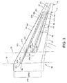
- FIG. 3 illustrates two horizontal tails 15, 16 for use with the aircraft 10 and, optionally, with the vertical tails 13, 14 of FIG. 2 and/or, optionally, with the canards 113, 113a, 114, 114a of FIG. 4 .
- the aft portion 18 of the fuselage 17 includes at least one front horizontal structural interface 37a, 37b, 37c, 37d, 37e, 37f and at least one rear horizontal structural interface 38a, 38b, 38c.
- the at least one front horizontal structural interface 37a, 37b, 37c may be disposed along the centerline 19 of the fuselage 17.
- the at least one front horizontal structural interface 37d, 37e, 37f may be disposed at the SOB 21.
- the at least one rear horizontal structural interface 38a, 38b, 38c may be disposed at the SOB 21.
- the at least one front horizontal structural interface 37a, 37b, 37c, 37d, 37e, 37f connects to a front spar 39a, 39b, 39c of the first horizontal tail 15 or to a front spar 42 of the second horizontal tail 15.
- the at least one rear horizontal structural interface 38a, 38b, 38c connects to a rear spar 41a, 41b, 41c of the first horizontal tail 15 or to a rear spar 43 of the second horizontal tail 16.
- the first and second horizontal tails 15, 16 are of different sizes, but the horizontal tails 15, 16 may also have one or more structural difference selected from the group consisting of shape, sweep angles of the leading edges 44, 45, sweep angles of the movable trailing edges 51, 52, sweep angles of the fixed trailing edges 46, 47, sweep angles of the front spars 39a, 39b, 39c, 42, sweep angles of the rear spars 41a, 41b, 41c, 43, the horizontal box chords 48, 48a, and/or the horizontal root chords 248a, 248 Multiple combinations are possible.
- first and second horizontal tails 15, 16 may have different sweep angles for at least one of the front spars 39a, 39b, 39c, 42 and/or the rear spars 41a, 41b, 41c, 43.
- first and second horizontal tails 15, 16 may each have a leading edge 44, 45 that defines a sweep angle wherein the sweep angle of the leading edge 44 of the first horizontal tail 15 is different from the sweep angle of the leading edge 45 of the second horizontal tail 16.
- first and second horizontal tails 15, 16 may each have a movable trailing edge 51, 52 that defines a sweep angle and wherein the sweep angle of the movable trailing edge 51 of the first horizontal tail 15 is different from the sweep angle of the movable trailing edge 52 of the second horizontal tail 16.
- first and second horizontal tails 15, 16 may each have a fixed trailing edge 46, 47 that defines a sweep angle and wherein the sweep angle of the fixed trailing edge 46 of the first horizontal tail 15 is different from the sweep angle of the fixed trailing edge 47 of the second horizontal tail 16.
- first horizontal tail 15 includes the front spar 39a and the rear spar 41b
- the spars 39a, 41b are separated by the horizontal box chord 48a.
- the front spars 39c, 42 and the rear spars 41c, 43 of the first and second horizontal tails 15, 16 are separated by a common horizontal box chord 48 as shown in FIG. 3 .
- the aircraft 10 includes a jackscrew interface 49 and the at least one front horizontal structural interface 37a, 37b, 37c of the aircraft 10 is in alignment with and/or connected to the jackscrew interface 49.
- the front and rear horizontal structural interfaces 37a, 37b, 37c, 37d, 37e, 37f, 38a, 38b, 38c may be separated by a horizontal box chord 48 that may be common to both the first and second horizontal tails 15, 16. While not required, the use of a common horizontal box chord 48 for each horizontal tail 15, 16 may reduce the number of structural interfaces required thereby reducing costs.
- Each horizontal tail 15, 16 also may include an elevator 251, 252.
- the rear canard structural interfaces 123a, 123b, 123c may be connected to a bulkhead 136 for purposes of strength and structural integrity.
- one of the front horizontal structural interfaces 37a, 37b, 37c, 37d, 37e, 37f connects to a front spar 39a, 39b, 39c of the first horizontal tail 15 while a different front horizontal structural interface 37a, 37b, 37c, 37d, 37e, 37f connects to a front spar 42 of the second horizontal tail 16.
- one of the rear horizontal structural interfaces 38a, 38b, 38c connects to the rear spar 41a, 41b, 41c of the first horizontal tail 15 while a different rear horizontal structural interface 38a, 38b, 38c connects to the rear spar 43 of the second horizontal tail 16.
- FIG. 4 illustrates three front canard structural interfaces 122a, 122b, 122c because the first canard 113 is illustrated with three possible front spars 127a, 127b, 127c.
- the first and second canards 113, 114 are equipped with elevators 234, 235.
- the front spar 128 of the second canard 114 while meeting the front spar 127c at the front canard structural interface 122c, does not need to be in alignment with the front spar 127c of the first canard 113.
- the front spar 127c is not in alignment with the front spar 128, only one front canard structural interface 122c is needed to accommodate both of these design choices.
- three rear canard structural interfaces 123a, 123b, 123c are shown because the first canard 113 includes three possible rear spars 129a, 129b, 129c, and the rear spar 129c of the first canard 113 shares a rear canard structural interface 123c with the rear spar 131 of the second canard 114 even though the rear spar 129c is not in alignment with the rear spar 131.
- only one rear canard structural interface 122c is needed to accommodate both of the rear spar 129c and the rear spar 131 of the canards 113, 114 respectively.
- the at least one front canard structural interface 122a, 122b, 122c connects to a front spar 127a, 127b, 127c of the first canard 113 or to the front spar 128 of the second canard 114.
- the at least one rear canard structural interface 123a, 123b, 123c connects to a rear spar 129a, 129b, 129c of the first canard 113 or to the rear spar 131 of the second canard 114.
- the first and second canards 113, 114 are of different sizes, however, the first and second canards 113, 114 may also differ in other ways as well.
- first and second canards 113, 114 each define a sweep angle
- rear spars 129a, 129b, 129c, 131 of the first and second canards 113, 114 also each define a sweep angle.
- first and second canards 113, 114 each have a leading edge 132, 133 that defines a sweep angle
- the first and second canards 113, 114 each have a fixed trailing edge 334, 335 and a movable trailing edge 134, 135 that each defines a sweep angle
- the first and second canards 113, 114 each have a fixed trailing edge 334, 335 and a movable trailing edge 134, 135 that each defines a sweep angle
- the first and second canards 113, 114 each include a canard box chord 124a, 124 that may or may not be the same. For example, a different canard box chord 124a for the canard 113 is shown in FIG. 4 .
- the first and second canards 113, 114 may have at least one structural difference selected from the group consisting of different sweep angles of the front spars 127a, 127b, 127c, 128, different sweep angles of the rear spars 129a, 129b, 129c, 131, different sweep angles of the leading edges 132, 133, different sweep angles of the fixed trailing edges 334, 335, different sweep angles of the movable trailing edges 134, 135, different canard box chords 124a, 124, and/or different canard root chords 324a, 324.
- the front and rear canard structural interfaces 122c, 123c may be separated by a canard box chord 124 that may be common to both the first and second canards 113, 114. While not required, the use of a common canard box chord 124 for each canard 113, 114 may reduce the number of structural interfaces required thereby reducing costs.
- Each canard 113, 114 also may include an elevator 235, 234.
- the rear canard structural interfaces 123a, 123b, 123c may be connected to a bulkhead 136 for purposes of strength and structural integrity.
- the first and second canards 113, 114 have different sweep angles for at least the front spars 127a, 127b, 127c, 128 and the rear spars 129a, 129b, 129c, 131, which illustrate the versatility of the disclosed embodiments.
- the first and second canards 113, 114 each have a leading edge 132, 133 that defines a sweep angle and the sweep angle of the leading edge 132 of the first canard 113 is different from the sweep angle of the leading edge 133 of the second canard 114.
- first and second canards 113, 114 each have a movable trailing edge 134, 135 that defines a sweep angle and the sweep angle of the movable trailing edge 134 of the first canard 113 is different from the sweep angle of the movable trailing edge 135 of the second canard 114.
- first and second canards 113, 114 each have a fixed trailing edge 334, 335 that defines a sweep angle, and the sweep angle of the fixed trailing edge 334 of the first canard 113 is different from the sweep angle of the fixed trailing edge 335 of the second canard 114.
- the forward portion 118 of the fuselage 17 is versatile and enables an aircraft designer to inexpensively provide a family of aircraft 10, each family member having a fuselage 17 with a common forward portion 118 that may accommodate canards 113, 114 of different sizes that may also have different sweep angles at the leading edges 132, 133, different sweep angles at the movable trailing edges 134, 135, different sweep angles at the fixed trailing edges 334, 335, different sweep angles at the front spars 127a, 127b, 127c, 128, different sweep angles at the rear spars 129a, 129b, 129c, 131, different canard box chords 124a, 124, and/or different canard root chords 324a, 324.
- the front spar 127a, 127b of the first canard 113 may connect to a first front canard structural interface 122a, 122b while the front spar 128 of the second canard 114 may connect to a second front canard structural interface 122c, wherein the first front canard structural interface 122a, 122b is different from the second front canard structural interface 122c.
- the rear spar 129a, 129b of the first canard 113 may connect to a first rear canard structural interface 123a, 123b while the rear spar 131 of the second canard 114 may connect to a second rear canard structural interface 123c, wherein the first rear canard structural interface 123a, 123b is different from the second rear canard structural interface 123c.
- the aircraft 10 also includes one or more of a vertical tail 13, 14, a horizontal tail, 15, 16 and a canard 113, 114.
- the method comprises, wherein if the aircraft 10 has a vertical tail 13, 14, providing the aft portion 18 of the fuselage 17 with at least one front vertical structural interface 22a, 22b, 22c and at least one rear vertical structural interface 23a, 23b, 23c.
- the aircraft 10 has a horizontal tail 15, 16, providing the aft portion 18 of the fuselage 17 with at least one front horizontal structural interface 37a, 37b, 37c and at least one rear horizontal structural interface 38a, 38b, 38c.
- the aircraft 10 has a canard 113, 114, providing the forward portion 118 of the fuselage 17 with at least one front canard structural interface 122a, 122b, 122c and at least one rear canard structural interface 123a, 123b, 123c.
- the method further comprises making at least one enhancement to the aircraft 10 selected from the group consisting of:
- the differences between the vertical tails 13, 14 may improve the performance of the aircraft 10 in addition to reducing manufacturing costs.
- the front spars 27a, 27b, 27c, 28 of the first and second vertical tails 13, 14 each define a sweep angle
- the rear spars 29a, 29b, 29c, 31 of the first and second vertical tails 13, 14 each define a sweep angle.
- the first and second vertical tails 13, 14 each have a leading edge 32, 33 that defines a sweep angle
- the first and second vertical tails 13, 14 each have a movable trailing edge 25, 26 that defines a sweep angle
- the first and second vertical tails 13, 14 each have a fixed trailing edge 34, 35 that defines a sweep angle.
- the first and second vertical tails 13, 14 each further include a vertical box chord 24a, 24.
- the first and second vertical tails 13, 14 may have at least one structural difference selected from the group consisting of different sizes; different sweep angles of the front spars 27a, 27b, 27c, 28; different sweep angles of the rear spars 29a, 29b, 29c, 31; different sweep angles of the leading edges 32, 33; different sweep angles of the movable trailing edges 25, 26; different sweep angles of the fixed trailing edges 34, 35; different vertical box chords 24a, 24a; and/or different vertical root chords 224a, 224.
- the optimum vertical tail 13, 14 may be selected based on a variety of criteria, which may improve the performance of the aircraft 10 as well as reducing its cost.
- the differences between the horizontal tails 15, 16 may also improve the performance or operation of the aircraft 10 in addition to reducing manufacturing costs.
- the front spars 39a, 39b, 39c, 42 of the first and second horizontal tails 15, 16 each define a sweep angle
- the rear spars 41a, 41b, 41c, 43 of the first and second horizontal tails 15, 16 each define a sweep angle.
- the first and second horizontal tails 15, 16 each have a leading edge 44, 45 that defines a sweep angle
- the first and second horizontal tails 15, 16 each have a fixed trailing edge 46, 47 that defines a sweep angle
- the first and second horizontal tails 15, 16 each have a movable trailing edge 51, 52 that defines a sweep angle.
- the first and second horizontal tails 15, 16 may have at least one structural difference selected from the group consisting of different sizes; different sweep angles of the front spars 39a, 39b, 39c, 42; different sweep angles of the rear spars 41a, 41b, 41c, 43; different sweep angles of the leading edges 44, 45; different sweep angles of the fixed trailing edges 46, 47; different sweep angles of the movable trailing edges 51, 52; different horizontal box chords 48a, 48; and/or different horizontal root chords 248a, 248.
- the differences between the canards 113, 114, if utilized, may improve the performance of the aircraft 10 in addition to reducing manufacturing costs.
- the front spars 127a, 127b, 127c, 128 of the first and second canards 113, 114 each define a sweep angle
- the rear spars 129a, 129b, 129c, 131 of the first and second canards 113, 114 each define a sweep angle.
- first and second canards 113, 114 each have a leading edge 132, 133 that defines a sweep angle
- the first and second canards 113, 114 each have a movable trailing edge 134, 135 that defines a sweep angle
- the first and second canards 113, 114 each have a fixed trailing edge 334, 335 that defines a sweep angle.
- the first and second canards 113, 114 each further include a canard box chord 124a, 124.
- the first and second canards 113, 114 may have at least one structural difference selected from the group consisting of different sizes; different sweep angles of the front spars 127a, 127b, 127c, 128; different sweep angles of the rear spars 129a, 129b, 129c, 131; different sweep angles of the leading edges 132, 133; different sweep angles of the movable trailing edges 134, 135; different sweep angles of the fixed trailing edges 334, 335, different canard box chords 124a, 124; and/or different canard root chords 324a, 324.
- the aft portion 18 of the fuselage 17 is designed to be versatile so it may be connected to one of a variety of vertical tails 13, 14 and/or to one of a variety of horizontal tails 15, 16 without the need to redesign or reconfigure the structural layout of the aft portion 18 of the fuselage 17.
- the forward portion 118 of the fuselage is also designed to be versatile so it may be connected to a variety of canards 113, 114. This versatility can be exploited by selecting vertical tails 13, 14, horizontal tails 15, 16 and/or canards 113, 114 that will enhance the performance of the aircraft.
- a family of aircraft 10 may be provided using fuselages 17 having a common aft portion 18 that is equipped with a configuration of four or more structural interfaces 22a, 22b, 22c, 23a, 23b, 23c, 37a, 37b, 37c, 37d, 37e, 37f, 38a, 38b, 38c that enable the aft portion 18 to be connected to a variety of different vertical tails 13,14 and/or a variety of horizontal tails 15, 16.
- the versatility described herein may result in reduced manufacturing costs in addition to improved aircraft performance.
Landscapes
- Engineering & Computer Science (AREA)
- Aviation & Aerospace Engineering (AREA)
- Mechanical Engineering (AREA)
- Tires In General (AREA)
- Aiming, Guidance, Guns With A Light Source, Armor, Camouflage, And Targets (AREA)
- Pressure Welding/Diffusion-Bonding (AREA)
- Traffic Control Systems (AREA)
Abstract
Description
- This disclosure relates generally airplanes having fuselage structures that can accommodate vertical tails, horizontal tails and canards of different structural configurations.
- The aft portion of an aircraft fuselage includes structural interfaces for connecting the aft portion to a vertical tail and/or to a horizontal tail. The vertical tail and the horizontal tail each include a front spar and a rear spar. Typically, the aft end of the fuselage will include four structural interfaces, including two structural interfaces for connection to the front and rear spars of the vertical tail and two structural interfaces for connection to the front and rear spars of the horizontal tail. The structural interfaces that connect the vertical tail to the fuselage are typically disposed along the top or crown of the fuselage. In contrast, the horizontal tail typically passes through the aft end of the fuselage and the interface used to connect the front spar of the horizontal tail to the fuselage is disposed along the centerline of the fuselage, typically at the jackscrew or the device used to adjust the trim of the horizontal tail. Further, the structural interface used to connect the rear spar of the horizontal tail to the fuselage is typically located at the side of body (SOB) of the fuselage in alignment with the pivot point or pivot interface, which connects to both sides (left and right) of the horizontal tail.
- The forward portion of an aircraft fuselage may include structural interfaces for connecting the forward portion to a canard. The canard includes a front spar and a rear spar. The forward portion of the fuselage will include two structural interfaces (one per side, left and right) for connection to the front and rear spars of the canard. The structural interfaces that connect the canard to the fuselage are typically located at the side of body (SOB) of the fuselage.
- When an aircraft manufacturer desires to change the vertical tail and/or the horizontal tail, such as the size, shape or sweep angle(s) of the tail or tail, the aft end of the fuselage must undergo significant modifications or redesign to accommodate a different vertical tail and/or a different horizontal tail. Similarly, when an aircraft manufacturer desires to change the canard, such as the size, shape, or sweep angle(s) of the canard, the forward end of the fuselage must undergo significant modifications or redesign to accommodate a different canard.
- An aircraft is disclosed which comprises a fuselage that comprises an aft portion. The aft portion comprises at least one front vertical structural interface and at least one rear vertical structural interface. The at least one front vertical structural interface is connected to a front spar of a first vertical tail or to a front spar of a second vertical tail. The at least one rear vertical structural interface is connected to a rear spar of the first vertical tail or to a rear spar of the second vertical tail. The first and second vertical tails are of different sizes.
- Another aircraft is disclosed which also comprises a fuselage that comprises an aft portion. The fuselage is defined by a centerline that extends through the fuselage and a side of body (SOB) that surrounds the centerline. The aft portion includes at least one front horizontal structural interface and at least one rear horizontal structural interface. The at least one front horizontal structural interface is disposed along the centerline and the at least one rear horizontal structural interface is disposed at the SOB. The at least one front horizontal structural interface is connected to a front spar of a first horizontal tail or to a front spar of a second horizontal tail. The at least one rear horizontal structural interface is connected to a rear spar of the first horizontal tail or to a rear spar of the second horizontal tail. The first and second horizontal tails are of different sizes.
- Another aircraft is disclosed which comprises a fuselage that comprises a forward portion. The fuselage is defined by a centerline that extends through the fuselage and a side of body (SOB) that surrounds the centerline. The forward portion includes at least one front canard structural interface and at least one rear canard structural interface. The at least one front canard structural interface is connected to a front spar of a first canard or to a front spar of a second canard. The at least one rear canard structural interface is connected to a rear spar of the first canard or to a rear spar of the second canard. The first and second canards are of different sizes.
- A method of enhancing an aircraft is disclosed wherein the aircraft has a fuselage with an aft portion and a forward portion. The aircraft also includes one or more of a vertical tail, a horizontal tail and a canard. The method comprises, wherein if the aircraft has a vertical tail, providing the aft portion of the fuselage with at least one front vertical structural interface and at least one rear vertical structural interface, and wherein if the aircraft has a horizontal tail, providing the aft portion of the fuselage with at least one front horizontal structural interface and at least one rear horizontal structural interface, and wherein if the aircraft has a canard, providing the forward portion of the fuselage with at least one front canard structural interface and at least one rear canard structural interface.
- The method further comprises making at least one enhancement to the aircraft selected from the group consisting of:
- allowing the at least one front vertical structural interface to connect to a front spar of a first vertical tail and allowing the at least one rear vertical structural interface to connect to a rear spar of the first vertical tail or, in the alternative, allowing the at least one front vertical structural interface to connect to a front spar of a second vertical tail and allowing the at least one rear vertical structural interface to connect a rear spar of the second vertical tail, wherein the first and second vertical tails are of different sizes;
- allowing the at least one front horizontal structural interface to connect to a front spar of a first horizontal tail and allowing the at least one rear horizontal structural interface to connect to a rear spar of the first horizontal tail or, in the alternative, allowing the at least one front horizontal structural interface to connect to a front spar of a second horizontal tail and allowing the at least one rear horizontal structural interface to connect to a rear spar of the second horizontal tail, wherein the first and second horizontal tails are of different sizes; and
- allowing the at least one front canard structural interface to connect to a front spar of a first canard and allowing the at least one rear canard structural interface to connect to a rear spar of the first canard or, in the alternative, allowing the at least one front canard structural interface to connect to a front spar of a second canard and allowing the at least one rear canard structural interface to connect to a rear spar of the second canard, wherein the first and second canards are of different sizes.
- The invention can involve an aircraft that may include a fuselage comprising an aft portion,
the aft portion including at least one front vertical structural interface and at least one rear vertical structural interface, the at least one front vertical structural interface connected to a front spar of a first vertical tail or to a front spar of a second vertical tail, the at least one rear vertical structural interface connected to a rear spar of a first vertical tail or to a rear spar of a second vertical tail, wherein the first and second vertical tails are of different sizes. The front spars of the first and second vertical tails may each define a sweep angle, and the rear spars of the first and second vertical tails may each define a sweep angle, the first and second vertical tails each have a leading edge that defines a sweep angle, the first and second vertical tails each have at least one trailing edge that defines a sweep angle, the first and second vertical tails each have a vertical box chord, the first and second vertical tails each have a vertical root chord, wherein the first and second vertical tails have at least one structural difference selected from the group consisting of different sweep angles of the front spars, different sweep angles of the rear spars, different sweep angles of the leading edges, different sweep angles of the trailing edges, different vertical box chords, and different vertical root chords. The front spar of the first vertical tail may be connected to a first front vertical structural interface and the front spar of the second vertical tail is connected to a second front vertical structural interface, the first front vertical structural interface being different from the second front vertical structural interface. The rear spar of the first vertical tail may be connected to a first rear vertical structural interface and the rear spar of the second vertical tail may be connected to a second rear vertical structural interface, the first rear vertical structural interface being different from the second rear vertical structural interface. This can enhance performance of the aerodynamics and improve structural reliability. The aft portion of the fuselage may include at least one front horizontal structural interface and at least one rear horizontal structural interface, the at least one front horizontal structural interface connected to a front spar of a first horizontal tail or to a front spar of a second horizontal tail, the at least one rear horizontal structural interface connected to a rear spar of the first horizontal tail or to a rear spar of the second horizontal tail, therein the front spars of the first and second horizontal tails each define a sweep angle, the rear spars of the first and second horizontal tails each define a sweep angle, the first and second horizontal tails each have a leading edge that defines a sweep angle, the first and second horizontal tails each have at least one trailing edge that each defines a sweep angle, the first and second horizontal tails each have a horizontal box chord, the first and second horizontal tails each have a horizontal root chord, and the first and second horizontal tails each have a size, wherein the first and second horizontal tails have at least one structural difference selected from the group consisting of different sweep angles of the front spars, different sweep angles of the rear spars, different sweep angles of the leading edges, different sweep angles of the trailing edges, different horizontal box chords, different horizontal root chords, and/or different sizes. The front spar of the first horizontal tail may be connected to a first front horizontal structural interface and the front spar of the second horizontal tail is connected to a second front horizontal structural interface, the first front horizontal structural interface being different from the second front horizontal structural interface. The rear spar of the first horizontal tail may be connected to a first rear horizontal structural interface and the rear spar of the second horizontal tail is connected to a second rear horizontal structural interface, the first rear horizontal structural interface being different from the second rear horizontal structural interface. The fuselage further may include a forward portion, the forward portion including at least one front canard structural interface and at least one rear canard structural interface, the at least one front canard structural interface connected to a front spar of a first canard or to a front spar of a second canard, the at least one rear canard structural interface connected to a rear spar of the first canard or to a rear spar of the second canard, wherein the front spars of the first and second canards each define a sweep angle, the rear spars of the first and second canards each define a sweep angle, the first and second canards each have a leading edge that defines a sweep angle, the first and second canards each have at least one trailing edge that each defines a sweep angle, the first and second canards each have a canard box chord, the first and second canards each have a canard root chord, and the first and second canards each have a size, wherein the first and second canards have at least one structural difference selected from the group consisting of different sweep angles of the front spars, different sweep angles of the rear spars, different sweep angles of the leading edges, different sweep angles of the trailing edges, different canard box chords, different canard root chords, and/or different sizes. The front spar of the first canard may be connected to a first front canard structural interface and the front spar of the second canard is connected to a second front canard structural interface, the first front canard structural interface being different from the second front canard structural interface. The rear spar of the first canard may be connected to a first rear canard structural interface and the rear spar of the second canard is connected to a second rear canard structural interface, the first rear canard structural interface being different from the second rear canard structural interface. - The invention can involve an aircraft that may include a fuselage comprising an aft portion,
the aft portion including at least one front horizontal structural interface and at least one rear horizontal structural interface, the at least one front horizontal structural interface connected to a front spar of a first horizontal tail or to a front spar of a second horizontal tail, the at least one rear horizontal structural interface connected to a rear spar of the first horizontal tail or to a rear spar of the second horizontal tail, wherein the first and second horizontal tails are of different sizes. The front spars of the first and second horizontal tails each may define a sweep angle, the rear spars of the first and second horizontal tails each may define a sweep angle, the first and second horizontal tails each have a leading edge that defines a sweep angle, the first and second horizontal tails each have at least one trailing edge that each defines a sweep angle, the first and second horizontal tails each have a horizontal box chord, the first and second horizontal tails each have a horizontal root chord, wherein the first and second horizontal tails have at least one structural difference selected from the group consisting of different sweep angles of the front spars, different sweep angles of the rear spars, different sweep angles of the leading edges, different sweep angles of the trailing edges, different horizontal box chords, and/or different horizontal root chords. The front spar of the first horizontal tail is connected to a first front horizontal structural interface and the front spar of the second horizontal tail is connected to a second front horizontal structural interface, the first front horizontal structural interface being different from the second front horizontal structural interface. The rear spar of the first horizontal tail is connected to a first rear horizontal structural interface and the rear spar of the second horizontal tail is connected to a second rear horizontal structural interface, the first rear horizontal structural interface being different from the second rear horizontal structural interface. The aft portion of the fuselage includes at least one front vertical structural interface and at least one rear vertical structural interface, The at least one front vertical structural interface connected to a front spar of a first vertical tail or to a front spar of a second vertical tail, the at least one rear vertical structural interface connected to a rear spar of the first vertical tail or to a rear spar of the second vertical tail, wherein the front spars of first and second vertical tails each define a sweep angle, the rear spars of the first and second vertical tails each define a sweep angle, the first and second vertical tails each have a leading edge that defines a sweep angle, the first and second vertical tails each have at least one trailing edge that each defines a sweep angle, the first and second vertical tails each have a vertical box chord, the first and second vertical tails each have a vertical root chord, the first and second vertical tails each have a size, wherein the first and second vertical tails have at least one structural difference selected from the group consisting of different sweep angles of the front spars, different sweep angles of the rear spars, different sweep angles of the leading edges, different sweep angles of the trailing edges, different vertical box chords, different vertical root chords, and/or different sizes. The fuselage may further comprise a forward portion that includes at least one front canard structural interface and at least one rear canard structural interface, the at least one front canard structural interface connected to a front spar of a first canard or to a front spar of a second canard, the at least one rear canard structural interface connected to a rear spar of the first canard or to a rear spar of the second canard, wherein the front spars of the first and second canards each define a sweep angle, the rear spars of the first and second canards each define a sweep angle, the first and second canards each have a leading edge that defines a sweep angle, the first and second canards each have at least one trailing edge that each defines a sweep angle, the first and second canards each have a canard box chord, the first and second canards each have a canard root chord, the first and second canards each have a size, wherein the first and second canards have at least one structural difference selected from the group consisting of different sweep angles of the front spars, different sweep angles of the rear spars, different sweep angles of the leading edges, different sweep angles of the trailing edges, different canard box chords, different canard root chords, and/or different sizes. - The invention can involve an aircraft that may include a fuselage comprising a forward portion that includes at least one front canard structural interface and at least one rear canard structural interface, the at least one front canard structural interface connected to a front spar of a first canard or to a front spar of a second canard, the at least one rear canard structural interface connected to a rear spar of the first canard or to a rear spar of the second canard, wherein the first and second canards are of different sizes. The front spars of first and second canards each may define a sweep angle, the rear spars of the first and second canards each may define a sweep angle, the first and second canards each may have a leading edge that defines a sweep angle, the first and second canards each may have at least one trailing edge that each defines a sweep angle, the first and second canards each have a canard box chord, the first and second canards each have a horizontal root chord, wherein the first and second canards may have at least one structural difference selected from the group consisting of different sweep angles of the front spars, different sweep angles of the rear spars, different sweep angles of the leading edges, different sweep angles of the trailing edges, different canard box chords, and/or different canard root chords. These characteristics enhance the aerodynamics and structural integrity of the vehicle. The front spar of the first canard may be connected to a first front canard structural interface and the front spar of the second canard is connected to a second front canard structural interface, the first front canard structural interface being different from the second front canard structural interface. The rear spar of the first canard may be connected to a first rear canard structural interface and the rear spar of the second canard is connected to a second rear canard structural interface, the first rear canard structural interface being different from the second rear canard structural interface. The fuselage may further comprise an aft portion that includes at least one front vertical structural interface and at least one rear vertical structural interface, the at least one front vertical structural interface connected to a front spar of a first vertical tail or to a front spar of a second vertical tail, the at least one rear vertical structural interface connected to a rear spar of the first vertical tail or to a rear spar of the second vertical tail, wherein the front spars of the first and second vertical tails each define a sweep angle, the rear spars of the first and second vertical tails each define a sweep angle, the first and second vertical tails each have a leading edge that defines a sweep angle, the first and second vertical tails each have at least one trailing edge that each defines a sweep angle, the first and second vertical tails each have a vertical box chord, the first and second vertical tails each have a vertical root chord, the first and second vertical tails each have a size, wherein the first and second vertical tails have at least one structural difference selected from the group consisting of different sweep angles of the front spars, different sweep angles of the rear spars, different sweep angles of the leading edges, different sweep angles of the trailing edges, different vertical box chords, different vertical root chords, and/or different sizes. The fuselage may further comprises an aft portion that includes at least one front horizontal structural interface and at least one rear horizontal structural interface, the at least one front horizontal structural interface connected to a front spar of a first horizontal tail or to a front spar of a second horizontal tail, the at least one rear horizontal structural interface connected to a rear spar of the first horizontal tail or to a rear spar of the second horizontal tail, wherein the front spars of the first and second horizontal tails each define a sweep angle, the rear spars of the first and second horizontal tails each define a sweep angle, the first and second horizontal tails each have a leading edge that defines a sweep angle, the first and second horizontal tails each have at least one trailing edge that each defines a sweep angle, the first and second horizontal tails each have a horizontal box chord, the first and second horizontal tails each have a horizontal root chord, and the first and second horizontal tails each have a size, wherein the first and second horizontal tails have at least one structural difference selected from the group consisting of different sweep angles of the front spars, different sweep angles of the rear spars, different sweep angles of the leading edges, different sweep angles of the trailing edges, different horizontal box chords, different horizontal root chords, and/or different sizes.
- The invention can involve a method of enhancing an aircraft that may include a fuselage with an aft portion and a forward portion, the aircraft including one or more of a vertical tail, a horizontal tail and a canard, the method comprising: wherein if the aircraft has a vertical tail, providing the aft portion of the fuselage with at least one front vertical structural interface and at least one rear vertical structural interface, wherein if the aircraft has a horizontal tail, providing the aft portion of the fuselage with at least one front horizontal structural interface and at least one rear horizontal structural interface, wherein if the aircraft has a canard, providing the forward portion of the fuselage with at least one front canard structural interface and at least one rear canard structural interface, the method further comprising making at least one enhancement to the aircraft selected from the group consisting of: allowing the at least one front vertical structural interface to connect to a front spar of a first vertical tail and allowing the at least one rear vertical structural interface to connect to a rear spar of the first vertical tail or, in the alternative, allowing the at least one front vertical structural interface to connect to a front spar of a second vertical tail and allowing the at least one rear vertical structural interface to connect a rear spar of the second vertical tail, wherein the first and second vertical tails are of different sizes; allowing the at least one front horizontal structural interface to connect to a front spar of a first horizontal tail and allowing the at least one rear horizontal structural interface to connect to a rear spar of the first horizontal tail or, in the alternative, allowing the at least one front horizontal structural interface to connect to a front spar of a second horizontal tail and allowing the at least one rear horizontal structural interface to connect to a rear spar of the second horizontal tail, wherein the first and second horizontal tails are of different sizes; and allowing the at least one front canard structural interface to connect to a front spar of a first canard and allowing the at least one rear canard structural interface to connect to a rear spar of the first canard or, in the alternative, allowing the at least one front canard structural interface to connect to a front spar of a second canard and allowing the at least one rear canard structural interface to connect to a rear spar of the second canard, wherein the first and second canards are of different sizes.
- Other advantages and features will be apparent from the following detailed description when read in conjunction with the attached drawings.
- For a more complete understanding of the disclosed methods and apparatuses, reference should be made to the embodiment illustrated in greater detail on the accompanying drawings, wherein:
-
FIG. 1 schematically illustrates an aircraft capable of connection to different vertical tails, different horizontal tails and different canards. -
FIG. 2 schematically illustrates different vertical tails for connection to the aircraft ofFIG. 1 . -
FIG. 3 schematically illustrates different horizontal tails for connection to the aircraft ofFIG. 1 . -
FIG. 4 schematically illustrates different canards for connection to the aircraft ofFIG. 1 . - It should be understood that the drawings are not to scale and that the disclosed embodiments are sometimes illustrated diagrammatically and in partial views. In certain instances, details which are not necessary for an understanding of the disclosed methods and apparatuses or which render other details difficult to perceive may have been omitted. It should be understood, of course, that this disclosure is not limited to the particular embodiments illustrated herein.
-
FIGS. 1-3 illustrate anaircraft 10 that is capable of connection to differentvertical tails horizontal tails different canards vertical tails horizontal tails canards vertical tails horizontal tails canards vertical tail horizontal tail canard vertical tail horizontal tail canard - Further, the term "root chord" means the distance from the leading edge to the trailing edge at the fuselage interface and the term "box chord" means the distance from the front spar to the rear spar at the fuselage interface. In addition, vertical tails typically include a rudder and horizontal tails and canards typically include an elevator. The trailing edges of the rudders and elevators are referred to as "movable trailing edges" and the trailing edge of the main structure of a vertical tail, horizontal tail and canard is referred to as a "fixed trailing edge." However, some tails or canards may not have a rudder or elevator and therefore only one trailing edge, which moves or pivots with the rest of the structure. Therefore, the term trailing edge without the fixed or movable modifiers refers to both fixed and movable trailing edges.
- As shown in
FIG. 1 , theaircraft 10 includes afuselage 17 having anaft portion 18 and aforward portion 118. Thefuselage 17 may include acrown 20 that extends along the top of thefuselage 17 as shown inFIG. 2 . Thefuselage 17 may also include acenterline 19 that extends through thefuselage 17 and a side of body (SOB) 21 that surrounds thecenterline 19 as shown inFIG. 3 . Theaft portion 18 of thefuselage 17 may include a plurality of structural interfaces for connecting theaft portion 18 to one of a variety ofvertical tails aft portion 18 to one of a variety ofhorizontal tails forward portion 118 may include a plurality of structural interfaces for connecting theforward portion 118 to a variety ofcanards forward portions fuselage 17 enables aircraft designers to changevertical tails horizontal tails canards forward portions fuselage 17. While the drawings show only twovertical tails horizontal tails canards forward portions fuselage 17, thereby enabling an aircraft designer to inexpensively provide a family of aircraft that have a common aft andforward portions vertical tails horizontal tails different canards -
FIG. 2 illustrates twovertical tails aircraft 10. The firstvertical tail 13 is illustrated in phantom lines and with three possiblefront spars rear spars vertical tail 14 includes just a singlefront spar 28 and a singlerear spar 31. As shown inFIG. 2 , thevertical tails aft portion 18 of thefuselage 17 comprises at least one front verticalstructural interface structural interface - In
FIG. 2 , three front verticalstructural interfaces vertical tail 13 is illustrated with three possiblefront spars front spar 28 of the secondvertical tail 14, while meeting thefront spar 27c at the front verticalstructural interface 22c, does not need to be in alignment with thefront spar 27c of the firstvertical tail 13. In the example shown, even though thefront spar 27c is not in alignment with thefront spar 28, only one front verticalstructural interface 22c is needed to accommodate both of these design choices. However, in the case where none of thefront spars vertical tail 13 can share astructural interface front spar 28 of the secondvertical tail 14, then additional front verticalstructural interfaces FIG. 2 , three rear verticalstructural interfaces vertical tail 13 includes three possiblerear spars rear spar 29c of the firstvertical tail 13 shares a rear verticalstructural interface 23c with therear spar 31 of the secondvertical tail 14 even though therear spar 29c is not in alignment with therear spar 31. Thus, only one front verticalstructural interface 22c is needed to accommodate both of therear spar 29c and therear spar 31 of thevertical tails rear spars vertical tail 13 can share astructural interface rear spar 31 of the secondvertical tail 14, then additional rear verticalstructural interfaces - In the embodiment shown in
FIG. 2 , the at least one front verticalstructural interface front spar vertical tail 13 or to thefront spar 28 of the secondvertical tail 14. Similarly, the at least one rear verticalstructural interface rear spar vertical tail 13 or to therear spar 31 of the secondvertical tail 14. As shown inFIG. 2 , the first and secondvertical tails vertical tails front spars vertical tails rear spars vertical tails vertical tails leading edge vertical tails movable trailing edge vertical tails edge vertical tails vertical box chord vertical box chord 24a for thevertical tail 13 is shown inFIG. 2 . In an embodiment, in addition to different sizes or as an alternative to different sizes, the first and secondvertical tails front spars rear spars leading edges movable trailing edges edges vertical box chords vertical root chords - The front and rear vertical
structural interfaces crown 20 of thefuselage 17. Further, the front and rear verticalstructural interfaces vertical box chord 24 that may be common to both the first and secondvertical tails vertical box chord 24 for eachvertical tail vertical tail rudder structural interfaces bulkhead 36 for purposes of strength and structural integrity. - In the embodiments shown in
FIG. 2 , the first and secondvertical tails front spars rear spars vertical tails leading edge edge 32 of the firstvertical tail 13 is different from the sweep angle of the leadingedge 33 of the secondvertical tail 14. In yet another example, the first and secondvertical tails movable trailing edge movable trailing edge 25 of the firstvertical tail 13 is different from the sweep angle of themovable trailing edge 26 of the secondvertical tail 14. Similarly, the first and secondvertical tails edge edge 34 of the firstvertical tail 13 is different from the sweep angle of the fixed trailingedge 35 of the secondvertical tail 14. Thus, theaft portion 18 of thefuselage 17 is versatile and enables an aircraft designer to inexpensively provide a family ofaircraft 10, each family member having afuselage 17 with acommon aft portion 18 that may accommodatevertical tails leading edges movable trailing edges edges front spars rear spars vertical box chords vertical root chords - In one design option, the
front spar vertical tail 13 may connect to a first front verticalstructural interface 22a, 22b while thefront spar 28 of the secondvertical tail 14 may connect to a second front verticalstructural interface 22c, wherein the first front verticalstructural interface 22a, 22b is different from the second front verticalstructural interface 22c. - Similarly, the
rear spar vertical tail 13 may connect to a first rear verticalstructural interface 23a, 23b while therear spar 31 of the secondvertical tail 14 may connect to a second rear verticalstructural interface 23c, wherein the first rear verticalstructural interface 23a, 23b is different from the second rear verticalstructural interface 23c. -
FIG. 3 illustrates twohorizontal tails aircraft 10 and, optionally, with thevertical tails FIG. 2 and/or, optionally, with thecanards FIG. 4 . Theaft portion 18 of thefuselage 17 includes at least one front horizontalstructural interface structural interface 38a, 38b, 38c. The at least one front horizontalstructural interface centerline 19 of thefuselage 17. In a further embodiment, the at least one front horizontalstructural interface SOB 21. The at least one rear horizontalstructural interface 38a, 38b, 38c may be disposed at theSOB 21. The at least one front horizontalstructural interface front spar horizontal tail 15 or to afront spar 42 of the secondhorizontal tail 15. Further, the at least one rear horizontalstructural interface 38a, 38b, 38c connects to arear spar horizontal tail 15 or to arear spar 43 of the secondhorizontal tail 16. In the embodiment shown inFIGS. 1 and3 , the first and secondhorizontal tails horizontal tails leading edges movable trailing edges edges front spars rear spars horizontal box chords horizontal root chords - For example, the first and second
horizontal tails front spars rear spars horizontal tails leading edge edge 44 of the firsthorizontal tail 15 is different from the sweep angle of the leadingedge 45 of the secondhorizontal tail 16. In another example, the first and secondhorizontal tails movable trailing edge movable trailing edge 51 of the firsthorizontal tail 15 is different from the sweep angle of themovable trailing edge 52 of the secondhorizontal tail 16. In another example, the first and secondhorizontal tails edge edge 46 of the firsthorizontal tail 15 is different from the sweep angle of the fixed trailingedge 47 of the secondhorizontal tail 16. In another example, when the firsthorizontal tail 15 includes thefront spar 39a and therear spar 41b, thespars horizontal box chord 48a. However, the front spars 39c, 42 and therear spars 41c, 43 of the first and secondhorizontal tails horizontal box chord 48 as shown inFIG. 3 . In another example, theaircraft 10 includes ajackscrew interface 49 and the at least one front horizontalstructural interface aircraft 10 is in alignment with and/or connected to thejackscrew interface 49. - The front and rear horizontal
structural interfaces horizontal box chord 48 that may be common to both the first and secondhorizontal tails horizontal box chord 48 for eachhorizontal tail horizontal tail structural interfaces bulkhead 136 for purposes of strength and structural integrity. - In one embodiment, one of the front horizontal
structural interfaces front spar horizontal tail 15 while a different front horizontalstructural interface front spar 42 of the secondhorizontal tail 16. Similarly, in an embodiment, one of the rear horizontalstructural interfaces 38a, 38b, 38c connects to therear spar horizontal tail 15 while a different rear horizontalstructural interface 38a, 38b, 38c connects to therear spar 43 of the secondhorizontal tail 16. -
FIG. 4 illustrates three front canardstructural interfaces first canard 113 is illustrated with three possiblefront spars second canards elevators front spar 128 of thesecond canard 114, while meeting thefront spar 127c at the front canardstructural interface 122c, does not need to be in alignment with thefront spar 127c of thefirst canard 113. In the example shown, even though thefront spar 127c is not in alignment with thefront spar 128, only one front canardstructural interface 122c is needed to accommodate both of these design choices. However, in the case where none of thefront spars first canard 113 can share a canardstructural interface front spar 128 of thesecond canard 114, then additional front canardstructural interfaces FIG. 4 , three rear canardstructural interfaces first canard 113 includes three possiblerear spars rear spar 129c of thefirst canard 113 shares a rear canard structural interface 123c with therear spar 131 of thesecond canard 114 even though therear spar 129c is not in alignment with therear spar 131. Thus, only one rear canardstructural interface 122c is needed to accommodate both of therear spar 129c and therear spar 131 of thecanards rear spars first canard 113 can share a rear canardstructural interface rear spar 131 of thesecond canard 114, then additional rear canardstructural interfaces - In the embodiment shown in
FIG. 4 , the at least one front canardstructural interface front spar first canard 113 or to thefront spar 128 of thesecond canard 114. Similarly, the at least one rear canardstructural interface rear spar first canard 113 or to therear spar 131 of thesecond canard 114. As shown inFIG. 4 , the first andsecond canards second canards front spars second canards rear spars second canards second canards leading edge second canards trailing edge movable trailing edge second canards trailing edge movable trailing edge second canards canard box chord canard box chord 124a for thecanard 113 is shown inFIG. 4 . In an embodiment, in addition to different sizes or as an alternative to different sizes, the first andsecond canards front spars rear spars leading edges edges movable trailing edges canard box chords canard root chords - The front and rear canard
structural interfaces 122c, 123c may be separated by acanard box chord 124 that may be common to both the first andsecond canards canard box chord 124 for eachcanard canard elevator structural interfaces bulkhead 136 for purposes of strength and structural integrity. - In the embodiments shown in
FIG. 4 , the first andsecond canards front spars rear spars second canards leading edge leading edge 132 of thefirst canard 113 is different from the sweep angle of theleading edge 133 of thesecond canard 114. In yet another example, the first andsecond canards movable trailing edge movable trailing edge 134 of thefirst canard 113 is different from the sweep angle of themovable trailing edge 135 of thesecond canard 114. Similarly, the first andsecond canards trailing edge edge 334 of thefirst canard 113 is different from the sweep angle of the fixed trailingedge 335 of thesecond canard 114. Thus, theforward portion 118 of thefuselage 17 is versatile and enables an aircraft designer to inexpensively provide a family ofaircraft 10, each family member having afuselage 17 with acommon forward portion 118 that may accommodatecanards leading edges movable trailing edges edges front spars rear spars canard box chords canard root chords - In one design option, the
front spar first canard 113 may connect to a first front canardstructural interface front spar 128 of thesecond canard 114 may connect to a second front canardstructural interface 122c, wherein the first front canardstructural interface structural interface 122c. - Similarly, the
rear spar first canard 113 may connect to a first rear canardstructural interface rear spar 131 of thesecond canard 114 may connect to a second rear canard structural interface 123c, wherein the first rear canardstructural interface - A method of enhancing an
aircraft 10 having afuselage 17 with anaft portion 18 and aforward portion 118. Theaircraft 10 also includes one or more of avertical tail canard aircraft 10 has avertical tail aft portion 18 of thefuselage 17 with at least one front verticalstructural interface structural interface aircraft 10 has ahorizontal tail aft portion 18 of thefuselage 17 with at least one front horizontalstructural interface structural interface 38a, 38b, 38c. And, wherein if theaircraft 10 has acanard forward portion 118 of thefuselage 17 with at least one front canardstructural interface structural interface aircraft 10 selected from the group consisting of: - allowing the at least one front vertical
structural interface front spar vertical tail 13 and allowing the at least one rear verticalstructural interface rear spar vertical tail 13 or, in the alternative, allowing the at least one front verticalstructural interface front spar 28 of a secondvertical tail 14 and allowing the at least one rear verticalstructural interface rear spar 31 of the secondvertical tail 14, wherein the first and secondvertical tails - allowing the at least one front horizontal
structural interface front spar horizontal tail 15 and allowing the at least one rear horizontalstructural interface 38a, 38b, 38c to connect to arear spar horizontal tail 15 or, in the alternative, allowing the at least one front horizontalstructural interface front spar 42 of a secondhorizontal tail 16 and allowing the at least one rear horizontalstructural interface 38a, 38b, 38c to connect to arear spar 43 of the secondhorizontal tail 16, wherein the first and secondhorizontal tails - allowing the at least one front canard
structural interface front spar first canard 113 and allowing the at least one rear canardstructural interface rear spar first canard 113 or, in the alternative, allowing the at least one front canardstructural interface front spar 128 of asecond canard 114 and allowing the at least one rear canardstructural interface rear spar 131 of thesecond canard 114, wherein the first andsecond canards - The differences between the
vertical tails aircraft 10 in addition to reducing manufacturing costs. The front spars 27a, 27b, 27c, 28 of the first and secondvertical tails rear spars vertical tails vertical tails leading edge vertical tails movable trailing edge vertical tails edge vertical tails vertical box chord vertical tails front spars rear spars leading edges movable trailing edges edges vertical box chords vertical root chords vertical tail aircraft 10 as well as reducing its cost. - The differences between the
horizontal tails aircraft 10 in addition to reducing manufacturing costs. For example, thefront spars horizontal tails rear spars horizontal tails horizontal tails leading edge horizontal tails edge horizontal tails movable trailing edge horizontal tails front spars rear spars leading edges edges movable trailing edges horizontal box chords horizontal root chords - The differences between the
canards aircraft 10 in addition to reducing manufacturing costs. The front spars 127a, 127b, 127c, 128 of the first andsecond canards rear spars second canards second canards leading edge second canards movable trailing edge second canards trailing edge second canards canard box chord second canards front spars rear spars leading edges movable trailing edges edges canard box chords canard root chords - Thus,
various aircraft 10 and a method of enhancing the performance of theaircraft 10 are disclosed in addition to reducing manufacturing costs. Theaft portion 18 of thefuselage 17 is designed to be versatile so it may be connected to one of a variety ofvertical tails horizontal tails aft portion 18 of thefuselage 17. Similarly, theforward portion 118 of the fuselage is also designed to be versatile so it may be connected to a variety ofcanards vertical tails horizontal tails canards aircraft 10 may be provided usingfuselages 17 having acommon aft portion 18 that is equipped with a configuration of four or morestructural interfaces aft portion 18 to be connected to a variety of differentvertical tails horizontal tails - While only certain embodiments have been set forth, alternatives and modifications will be apparent from the above description to those skilled in the art. These and other alternatives are considered equivalents and within the spirit and scope of this disclosure and the appended claims.
Claims (13)
- An aircraft (10) comprising:a fuselage (17) comprising an aft portion (18),the aft portion (18) including at least one front vertical structural interface and at least one rear vertical structural interface,the at least one front vertical structural interface (22) connected to a front spar of a first vertical tail (13) or to a front spar of a second vertical tail (14),the at least one rear vertical structural interface (23) connected to a rear spar of a first vertical tail (13) or to a rear spar of a second vertical tail (14),wherein the first and second vertical tails (13, 14) are of different sizes.
- The aircraft (10) of claim 1, wherein the front spars of the first and second vertical tails (13, 14) each define a sweep angle, the rear spars of the first and second vertical tails (13, 14) each define a sweep angle, the first and second vertical tails (13, 14) each have a leading edge that defines a sweep angle, the first and second vertical tails (13, 14) each have at least one trailing edge that defines a sweep angle, the first and second vertical tails (13, 14) each have a vertical box chord, the first and second vertical tail (13, 14) each have a vertical root chord,
wherein the first and second vertical tails (13, 14) have at least one structural difference selected from the group consisting of different sweep angles of the front spars, different sweep angles of the rear spars, different sweep angles of the leading edges, different sweep angles of the trailing edges, different vertical box chords, and different vertical root chords. - The aircraft (10) of claim 1 or claim 2, wherein the front spar of the first vertical tail (13) is connected to a first front vertical structural interface (22) and the front spar of the second vertical tail (14) is connected to a second front vertical structural interface (22), the first front vertical structural interface (22) being different from the second front vertical structural interface (22).
- The aircraft (10) of any of claims 1 to 3, wherein the rear spar of the first vertical tail (13) is connected to a first rear vertical structural interface (23) and the rear spar of the second vertical tail (14) is connected to a second rear vertical structural interface (23), the first rear vertical structural interface (23) being different from the second rear vertical structural interface (23).
- The aircraft (10) of any of claims 1 to 4, wherein the aft portion (18) of the fuselage (17) includes at least one front horizontal structural interface and at least one rear horizontal structural interface,
the at least one front horizontal structural interface connected to a front spar of a first horizontal tail or to a front spar of a second horizontal tail,
the at least one rear horizontal structural interface connected to a rear spar of the first horizontal tail or to a rear spar of the second horizontal tail,
wherein the front spars of the first and second horizontal tails each define a sweep angle, the rear spars of the first and second horizontal tails each define a sweep angle, the first and second horizontal tails each have a leading edge that defines a sweep angle, the first and second horizontal tails each have at least one trailing edge that each defines a sweep angle, the first and second horizontal tails each have a horizontal box chord, the first and second horizontal tails each have a horizontal root chord, and the first and second horizontal tails each have a size,
wherein the first and second horizontal tails have at least one structural difference selected from the group consisting of different sweep angles of the front spars, different sweep angles of the rear spars, different sweep angles of the leading edges, different sweep angles of the trailing edges, different horizontal box chords, different horizontal root chords, and/or different sizes. - The aircraft (10) of claim 5, wherein the front spar of the first horizontal tail is connected to a first front horizontal structural interface and the front spar of the second horizontal tail is connected to a second front horizontal structural interface, the first front horizontal structural interface being different from the second front horizontal structural interface.
- The aircraft (10) of claim 5, wherein the rear spar of the first horizontal tail is connected to a first rear horizontal structural interface and the rear spar of the second horizontal tail is connected to a second rear horizontal structural interface, the first rear horizontal structural interface being different from the second rear horizontal structural interface.
- The aircraft (10) of any of claims 1 to 7, wherein the fuselage (17) further comprises a forward portion (118),
the forward portion (118) including at least one front canard structural interface and at least one rear canard structural interface,
the at least one front canard structural interface connected to a front spar of a first canard or to a front spar of a second canard,
the at least one rear canard structural interface connected to a rear spar of the first canard or to a rear spar of the second canard,
wherein the front spars of the first and second canards each define a sweep angle, the rear spars of the first and second canards each define a sweep angle, the first and second canards each have a leading edge that defines a sweep angle, the first and second canards each have at least one trailing edge that each defines a sweep angle, the first and second canards each have a canard box chord, the first and second canards each have a canard root chord, and the first and second canards each have a size,
wherein the first and second canards have at least one structural difference selected from the group consisting of different sweep angles of the front spars, different sweep angles of the rear spars, different sweep angles of the leading edges, different sweep angles of the trailing edges, different canard box chords, different canard root chords, and/or different sizes. - The aircraft (10) of claim 8, wherein the front spar of the first canard is connected to a first front canard structural interface and the front spar of the second canard is connected to a second front canard structural interface, the first front canard structural interface being different from the second front canard structural interface.
- The aircraft (10) of claim 8, wherein the rear spar of the first canard is connected to a first rear canard structural interface and the rear spar of the second canard is connected to a second rear canard structural interface, the first rear canard structural interface being different from the second rear canard structural interface.
- A method of enhancing an aircraft (10) having a fuselage (17) with an aft portion (18) and a forward portion (118), the aircraft (10) including one or more of a vertical tail, a horizontal tail and a canard, the method comprising:wherein if the aircraft (10) has a vertical tail, providing the aft portion (18) of the fuselage (17) with at least one front vertical structural interface (22) and at least one rear vertical structural interface (23),wherein if the aircraft (10) has a horizontal tail, providing the aft portion (18) of the fuselage (17) with at least one front horizontal structural interface and at least one rear horizontal structural interface,wherein if the aircraft (10) has a canard, providing the forward portion (118) of the fuselage (17) with at least one front canard structural interface and at least one rear canard structural interface,the method further comprising making at least one enhancement to the aircraft (10) selected from the group consisting of:allowing the at least one front vertical structural interface (22) to connect to a front spar of a first vertical tail (13) and allowing the at least one rear vertical structural interface (23) to connect to a rear spar of the first vertical tail (13) or, in the alternative, allowing the at least one front vertical structural interface (22) to connect to a front spar of a second vertical tail (14) and allowing the at least one rear vertical structural interface (23) to connect a rear spar of the second vertical tail (14), wherein the first and second vertical tails (13, 14) are of different sizes;allowing the at least one front horizontal structural interface to connect to a front spar of a first horizontal tail and allowing the at least one rear horizontal structural interface to connect to a rear spar of the first horizontal tail or, in the alternative, allowing the at least one front horizontal structural interface to connect to a front spar of a second horizontal tail and allowing the at least one rear horizontal structural interface to connect to a rear spar of the second horizontal tail, wherein the first and second horizontal tails are of different sizes; andallowing the at least one front canard structural interface to connect to a front spar of a first canard and allowing the at least one rear canard structural interface to connect to a rear spar of the first canard or, in the alternative, allowing the at least one front canard structural interface to connect to a front spar of a second canard and allowing the at least one rear canard structural interface to connect to a rear spar of the second canard, wherein the first and second canards are of different sizes.
- An aircraft (10) comprising:a fuselage (17) comprising an aft portion (18),the aft portion (18) including at least one front horizontal structural interface and at least one rear horizontal structural interface,the at least one front horizontal structural interface connected to a front spar of a first horizontal tail or to a front spar of a second horizontal tail,the at least one rear horizontal structural interface connected to a rear spar of the first horizontal tail or to a rear spar of the second horizontal tail,wherein the first and second horizontal tails are of different sizes.
- An aircraft (10) comprising:a fuselage (17) comprising a forward portion (118) that includes at least one front canard structural interface and at least one rear canard structural interface,the at least one front canard structural interface connected to a front spar of a first canard or to a front spar of a second canard,the at least one rear canard structural interface connected to a rear spar of the first canard or to a rear spar of the second canard,wherein the first and second canards are of different sizes.
Applications Claiming Priority (1)
| Application Number | Priority Date | Filing Date | Title |
|---|---|---|---|
| US14/975,115 US9849966B2 (en) | 2015-12-18 | 2015-12-18 | Fuselage structure for accommodating tails and canards of different sizes and shapes |
Publications (2)
| Publication Number | Publication Date |
|---|---|
| EP3181443A1 true EP3181443A1 (en) | 2017-06-21 |
| EP3181443B1 EP3181443B1 (en) | 2019-11-06 |
Family
ID=56990320
Family Applications (1)
| Application Number | Title | Priority Date | Filing Date |
|---|---|---|---|
| EP16190299.4A Active EP3181443B1 (en) | 2015-12-18 | 2016-09-23 | Fuselage structure for accomodating tails and canards of different sizes and shapes |
Country Status (4)
| Country | Link |
|---|---|
| US (1) | US9849966B2 (en) |
| EP (1) | EP3181443B1 (en) |
| CN (1) | CN106892089B (en) |
| RU (1) | RU2728474C2 (en) |
Cited By (1)
| Publication number | Priority date | Publication date | Assignee | Title |
|---|---|---|---|---|
| WO2020201644A3 (en) * | 2019-04-01 | 2021-03-18 | Olivier Lamaille | High-lift device |
Families Citing this family (3)
| Publication number | Priority date | Publication date | Assignee | Title |
|---|---|---|---|---|
| CN110979630B (en) * | 2019-11-29 | 2021-06-01 | 中国商用飞机有限责任公司北京民用飞机技术研究中心 | Root joint and design method of spar root joint of composite vertical tail main box section considering damage safety |
| CN113358327B (en) * | 2021-08-10 | 2021-11-30 | 中国空气动力研究与发展中心高速空气动力研究所 | High-speed model horizontal tail 'return' deformation angle device with high horizontal tail layout |
| CN114379765A (en) * | 2021-12-30 | 2022-04-22 | 中电科芜湖通用航空产业技术研究院有限公司 | Unmanned aerial vehicle's front wing and unmanned aerial vehicle |
Citations (7)
| Publication number | Priority date | Publication date | Assignee | Title |
|---|---|---|---|---|
| US4417708A (en) * | 1982-05-12 | 1983-11-29 | Grumman Aerospace Corporation | Interchangeable wing aircraft |
| US5692704A (en) * | 1995-06-07 | 1997-12-02 | Buttgereit; Volker | Body tail unit for a commercial aircraft |
| US6070831A (en) * | 1997-02-05 | 2000-06-06 | Vassiliev; Anatoli J. | Aircraft for passenger and/or cargo transport |
| DE102005003297A1 (en) * | 2005-01-24 | 2006-07-27 | Eads Deutschland Gmbh | Horizontal and vertical tails connecting barrel shaped fuselage rear section for e.g. transport plane, has horizontal tail section with end frames firmly connected with each other by torsion boxes and longitudinally reinforced braces |
| US20110036941A1 (en) * | 2009-05-29 | 2011-02-17 | Airbus Operations (S.A.S) | Aircraft with a wing movable along the longitudinal axis of th fuselage |
| US20120292435A1 (en) * | 2010-08-12 | 2012-11-22 | Abe Karem | Multi-Role Aircraft with Interchangeable Mission Modules |
| CN103625631A (en) * | 2013-08-23 | 2014-03-12 | 中国航空工业集团公司西安飞机设计研究所 | Design method for vertical tail docking structure |
Family Cites Families (9)
| Publication number | Priority date | Publication date | Assignee | Title |
|---|---|---|---|---|
| US4427168A (en) | 1981-09-29 | 1984-01-24 | The Boeing Company | Variable camber leading edge mechanism with Krueger flap |
| WO1997034733A1 (en) | 1996-03-22 | 1997-09-25 | The Boeing Company | Determinant spar assembly |
| US6729577B2 (en) | 2000-12-08 | 2004-05-04 | Lockheed Martin Corporation | Tail-braced wing aircraft and configurations for achieving long supersonic range and low sonic boom |
| RU2328409C1 (en) * | 2006-09-29 | 2008-07-10 | Валерий Николаевич Сиротин | Maneuverable aircraft with canard wing |
| US7887009B2 (en) | 2007-12-05 | 2011-02-15 | The Boeing Company | Methods and systems for attaching aircraft wings to fuselages |
| FR2943039B1 (en) * | 2009-03-12 | 2012-09-28 | Airbus France | PLANE TANK-TAIL AND REVERSE ENGINE. |
| US9090326B2 (en) | 2010-10-13 | 2015-07-28 | The Boeing Company | Active flow control on a vertical stabilizer and rudder |
| US8746616B2 (en) | 2011-10-19 | 2014-06-10 | The Boeing Company | Mid-wing multi-deck airplane |
| EP2687437B1 (en) | 2012-07-16 | 2017-01-18 | Airbus Operations, S.L. | Aircraft lifting surface with variable sweep distribution along the span |
-
2015
- 2015-12-18 US US14/975,115 patent/US9849966B2/en not_active Expired - Fee Related
-
2016
- 2016-09-21 RU RU2016137666A patent/RU2728474C2/en active
- 2016-09-23 EP EP16190299.4A patent/EP3181443B1/en active Active
- 2016-11-14 CN CN201611002241.5A patent/CN106892089B/en active Active
Patent Citations (7)
| Publication number | Priority date | Publication date | Assignee | Title |
|---|---|---|---|---|
| US4417708A (en) * | 1982-05-12 | 1983-11-29 | Grumman Aerospace Corporation | Interchangeable wing aircraft |
| US5692704A (en) * | 1995-06-07 | 1997-12-02 | Buttgereit; Volker | Body tail unit for a commercial aircraft |
| US6070831A (en) * | 1997-02-05 | 2000-06-06 | Vassiliev; Anatoli J. | Aircraft for passenger and/or cargo transport |
| DE102005003297A1 (en) * | 2005-01-24 | 2006-07-27 | Eads Deutschland Gmbh | Horizontal and vertical tails connecting barrel shaped fuselage rear section for e.g. transport plane, has horizontal tail section with end frames firmly connected with each other by torsion boxes and longitudinally reinforced braces |
| US20110036941A1 (en) * | 2009-05-29 | 2011-02-17 | Airbus Operations (S.A.S) | Aircraft with a wing movable along the longitudinal axis of th fuselage |
| US20120292435A1 (en) * | 2010-08-12 | 2012-11-22 | Abe Karem | Multi-Role Aircraft with Interchangeable Mission Modules |
| CN103625631A (en) * | 2013-08-23 | 2014-03-12 | 中国航空工业集团公司西安飞机设计研究所 | Design method for vertical tail docking structure |
Non-Patent Citations (1)
| Title |
|---|
| DATABASE WPI Week 201430, Derwent World Patents Index; AN 2014-H61907 * |
Cited By (1)
| Publication number | Priority date | Publication date | Assignee | Title |
|---|---|---|---|---|
| WO2020201644A3 (en) * | 2019-04-01 | 2021-03-18 | Olivier Lamaille | High-lift device |
Also Published As
| Publication number | Publication date |
|---|---|
| RU2728474C2 (en) | 2020-07-29 |
| US20170174311A1 (en) | 2017-06-22 |
| RU2016137666A (en) | 2018-03-27 |
| US9849966B2 (en) | 2017-12-26 |
| CN106892089A (en) | 2017-06-27 |
| CN106892089B (en) | 2020-08-28 |
| EP3181443B1 (en) | 2019-11-06 |
| RU2016137666A3 (en) | 2020-02-06 |
Similar Documents
| Publication | Publication Date | Title |
|---|---|---|
| EP3181443B1 (en) | Fuselage structure for accomodating tails and canards of different sizes and shapes | |
| RU2639354C2 (en) | System and method for minimizing wave resistance by two-sided asymmetrical structure | |
| US6726149B2 (en) | Derivative aircraft and methods for their manufacture | |
| CN103648908B (en) | skid landing gear system | |
| ES2968805T3 (en) | airplane wing | |
| US10864983B2 (en) | Rib arrangement in a wing tip device | |
| JP2006502914A (en) | Slotted aircraft wing | |
| US9533750B2 (en) | Slat, wing of aircraft, flight control surface of aircraft, and aircraft | |
| CN103068674B (en) | fixed wing of aircraft | |
| RU2600413C1 (en) | Aircraft wing | |
| BR112015020484B1 (en) | AIRCRAFT | |
| CN103429492B (en) | Torsion box skin stiffened with non-parallel stringers | |
| EP3330174A1 (en) | Aircraft stabilizer leading edge integration with torsion box and fuselage | |
| CN113365912B (en) | Aircraft assembly with integrated spar-cap | |
| CN105270603B (en) | A kind of unmanned Fixed Wing AirVehicle of high aspect ratio | |
| US20160375998A1 (en) | Vertical take-off and landing drag rudder | |
| CN112623255A (en) | Method for calculating torsional rigidity of section of door frame area of airplane body | |
| Yu | Design and optimization of wing structure for a fixed-wing unmanned aerial vehicle (UAV) | |
| CN105235889A (en) | Self-adaptive rhombic wing layout of air vehicles | |
| CN110143282B (en) | Aircraft adopting high aspect ratio double-fuselage flying wing layout | |
| EP2687437A1 (en) | Aircraft lifting surface with variable sweep distribution along the span | |
| US20220111947A1 (en) | Aircraft portion with reduced wave drag | |
| US10981645B2 (en) | Drag reduction systems for aircraft | |
| CN100408428C (en) | slotted aircraft wing | |
| CN110940481B (en) | A high-speed wind tunnel dynamic derivative test model for a flying-wing aircraft |
Legal Events
| Date | Code | Title | Description |
|---|---|---|---|
| PUAI | Public reference made under article 153(3) epc to a published international application that has entered the european phase |
Free format text: ORIGINAL CODE: 0009012 |
|
| STAA | Information on the status of an ep patent application or granted ep patent |
Free format text: STATUS: REQUEST FOR EXAMINATION WAS MADE |
|
| 17P | Request for examination filed |
Effective date: 20160923 |
|
| AK | Designated contracting states |
Kind code of ref document: A1 Designated state(s): AL AT BE BG CH CY CZ DE DK EE ES FI FR GB GR HR HU IE IS IT LI LT LU LV MC MK MT NL NO PL PT RO RS SE SI SK SM TR |
|
| AX | Request for extension of the european patent |
Extension state: BA ME |
|
| RBV | Designated contracting states (corrected) |
Designated state(s): AL AT BE BG CH CY CZ DE DK EE ES FI FR GB GR HR HU IE IS IT LI LT LU LV MC MK MT NL NO PL PT RO RS SE SI SK SM TR |
|
| STAA | Information on the status of an ep patent application or granted ep patent |
Free format text: STATUS: EXAMINATION IS IN PROGRESS |
|
| 17Q | First examination report despatched |
Effective date: 20180517 |
|
| RIC1 | Information provided on ipc code assigned before grant |
Ipc: B64C 39/12 20060101ALN20181128BHEP Ipc: B64C 5/02 20060101ALI20181128BHEP Ipc: B64C 1/26 20060101AFI20181128BHEP Ipc: B64C 5/04 20060101ALI20181128BHEP |
|
| GRAP | Despatch of communication of intention to grant a patent |
Free format text: ORIGINAL CODE: EPIDOSNIGR1 |
|
| STAA | Information on the status of an ep patent application or granted ep patent |
Free format text: STATUS: GRANT OF PATENT IS INTENDED |
|
| RIC1 | Information provided on ipc code assigned before grant |
Ipc: B64C 5/04 20060101ALI20181207BHEP Ipc: B64C 1/26 20060101AFI20181207BHEP Ipc: B64C 39/12 20060101ALN20181207BHEP Ipc: B64C 5/02 20060101ALI20181207BHEP |
|
| INTG | Intention to grant announced |
Effective date: 20190115 |
|
| GRAJ | Information related to disapproval of communication of intention to grant by the applicant or resumption of examination proceedings by the epo deleted |
Free format text: ORIGINAL CODE: EPIDOSDIGR1 |
|
| STAA | Information on the status of an ep patent application or granted ep patent |
Free format text: STATUS: EXAMINATION IS IN PROGRESS |
|
| GRAP | Despatch of communication of intention to grant a patent |
Free format text: ORIGINAL CODE: EPIDOSNIGR1 |
|
| STAA | Information on the status of an ep patent application or granted ep patent |
Free format text: STATUS: GRANT OF PATENT IS INTENDED |
|
| INTC | Intention to grant announced (deleted) | ||
| RIC1 | Information provided on ipc code assigned before grant |
Ipc: B64C 5/02 20060101ALI20190528BHEP Ipc: B64C 39/12 20060101ALN20190528BHEP Ipc: B64C 5/04 20060101ALI20190528BHEP Ipc: B64C 1/26 20060101AFI20190528BHEP |
|
| INTG | Intention to grant announced |
Effective date: 20190612 |
|
| GRAS | Grant fee paid |
Free format text: ORIGINAL CODE: EPIDOSNIGR3 |
|
| GRAA | (expected) grant |
Free format text: ORIGINAL CODE: 0009210 |
|
| STAA | Information on the status of an ep patent application or granted ep patent |
Free format text: STATUS: THE PATENT HAS BEEN GRANTED |
|
| AK | Designated contracting states |
Kind code of ref document: B1 Designated state(s): AL AT BE BG CH CY CZ DE DK EE ES FI FR GB GR HR HU IE IS IT LI LT LU LV MC MK MT NL NO PL PT RO RS SE SI SK SM TR |
|
| REG | Reference to a national code |
Ref country code: GB Ref legal event code: FG4D |
|
| REG | Reference to a national code |
Ref country code: CH Ref legal event code: EP Ref country code: AT Ref legal event code: REF Ref document number: 1198412 Country of ref document: AT Kind code of ref document: T Effective date: 20191115 |
|
| REG | Reference to a national code |
Ref country code: IE Ref legal event code: FG4D |
|
| REG | Reference to a national code |
Ref country code: DE Ref legal event code: R096 Ref document number: 602016023671 Country of ref document: DE |
|
| REG | Reference to a national code |
Ref country code: NL Ref legal event code: MP Effective date: 20191106 |
|
| REG | Reference to a national code |
Ref country code: LT Ref legal event code: MG4D |
|
| PG25 | Lapsed in a contracting state [announced via postgrant information from national office to epo] |
Ref country code: PL Free format text: LAPSE BECAUSE OF FAILURE TO SUBMIT A TRANSLATION OF THE DESCRIPTION OR TO PAY THE FEE WITHIN THE PRESCRIBED TIME-LIMIT Effective date: 20191106 Ref country code: LT Free format text: LAPSE BECAUSE OF FAILURE TO SUBMIT A TRANSLATION OF THE DESCRIPTION OR TO PAY THE FEE WITHIN THE PRESCRIBED TIME-LIMIT Effective date: 20191106 Ref country code: SE Free format text: LAPSE BECAUSE OF FAILURE TO SUBMIT A TRANSLATION OF THE DESCRIPTION OR TO PAY THE FEE WITHIN THE PRESCRIBED TIME-LIMIT Effective date: 20191106 Ref country code: BG Free format text: LAPSE BECAUSE OF FAILURE TO SUBMIT A TRANSLATION OF THE DESCRIPTION OR TO PAY THE FEE WITHIN THE PRESCRIBED TIME-LIMIT Effective date: 20200206 Ref country code: NL Free format text: LAPSE BECAUSE OF FAILURE TO SUBMIT A TRANSLATION OF THE DESCRIPTION OR TO PAY THE FEE WITHIN THE PRESCRIBED TIME-LIMIT Effective date: 20191106 Ref country code: FI Free format text: LAPSE BECAUSE OF FAILURE TO SUBMIT A TRANSLATION OF THE DESCRIPTION OR TO PAY THE FEE WITHIN THE PRESCRIBED TIME-LIMIT Effective date: 20191106 Ref country code: LV Free format text: LAPSE BECAUSE OF FAILURE TO SUBMIT A TRANSLATION OF THE DESCRIPTION OR TO PAY THE FEE WITHIN THE PRESCRIBED TIME-LIMIT Effective date: 20191106 Ref country code: NO Free format text: LAPSE BECAUSE OF FAILURE TO SUBMIT A TRANSLATION OF THE DESCRIPTION OR TO PAY THE FEE WITHIN THE PRESCRIBED TIME-LIMIT Effective date: 20200206 Ref country code: PT Free format text: LAPSE BECAUSE OF FAILURE TO SUBMIT A TRANSLATION OF THE DESCRIPTION OR TO PAY THE FEE WITHIN THE PRESCRIBED TIME-LIMIT Effective date: 20200306 Ref country code: GR Free format text: LAPSE BECAUSE OF FAILURE TO SUBMIT A TRANSLATION OF THE DESCRIPTION OR TO PAY THE FEE WITHIN THE PRESCRIBED TIME-LIMIT Effective date: 20200207 |
|
| PG25 | Lapsed in a contracting state [announced via postgrant information from national office to epo] |
Ref country code: RS Free format text: LAPSE BECAUSE OF FAILURE TO SUBMIT A TRANSLATION OF THE DESCRIPTION OR TO PAY THE FEE WITHIN THE PRESCRIBED TIME-LIMIT Effective date: 20191106 Ref country code: HR Free format text: LAPSE BECAUSE OF FAILURE TO SUBMIT A TRANSLATION OF THE DESCRIPTION OR TO PAY THE FEE WITHIN THE PRESCRIBED TIME-LIMIT Effective date: 20191106 Ref country code: IS Free format text: LAPSE BECAUSE OF FAILURE TO SUBMIT A TRANSLATION OF THE DESCRIPTION OR TO PAY THE FEE WITHIN THE PRESCRIBED TIME-LIMIT Effective date: 20200306 |
|
| PG25 | Lapsed in a contracting state [announced via postgrant information from national office to epo] |
Ref country code: AL Free format text: LAPSE BECAUSE OF FAILURE TO SUBMIT A TRANSLATION OF THE DESCRIPTION OR TO PAY THE FEE WITHIN THE PRESCRIBED TIME-LIMIT Effective date: 20191106 |
|
| PG25 | Lapsed in a contracting state [announced via postgrant information from national office to epo] |
Ref country code: CZ Free format text: LAPSE BECAUSE OF FAILURE TO SUBMIT A TRANSLATION OF THE DESCRIPTION OR TO PAY THE FEE WITHIN THE PRESCRIBED TIME-LIMIT Effective date: 20191106 Ref country code: RO Free format text: LAPSE BECAUSE OF FAILURE TO SUBMIT A TRANSLATION OF THE DESCRIPTION OR TO PAY THE FEE WITHIN THE PRESCRIBED TIME-LIMIT Effective date: 20191106 Ref country code: ES Free format text: LAPSE BECAUSE OF FAILURE TO SUBMIT A TRANSLATION OF THE DESCRIPTION OR TO PAY THE FEE WITHIN THE PRESCRIBED TIME-LIMIT Effective date: 20191106 Ref country code: EE Free format text: LAPSE BECAUSE OF FAILURE TO SUBMIT A TRANSLATION OF THE DESCRIPTION OR TO PAY THE FEE WITHIN THE PRESCRIBED TIME-LIMIT Effective date: 20191106 Ref country code: DK Free format text: LAPSE BECAUSE OF FAILURE TO SUBMIT A TRANSLATION OF THE DESCRIPTION OR TO PAY THE FEE WITHIN THE PRESCRIBED TIME-LIMIT Effective date: 20191106 |
|
| REG | Reference to a national code |
Ref country code: DE Ref legal event code: R097 Ref document number: 602016023671 Country of ref document: DE |
|
| REG | Reference to a national code |
Ref country code: AT Ref legal event code: MK05 Ref document number: 1198412 Country of ref document: AT Kind code of ref document: T Effective date: 20191106 |
|
| PG25 | Lapsed in a contracting state [announced via postgrant information from national office to epo] |
Ref country code: SK Free format text: LAPSE BECAUSE OF FAILURE TO SUBMIT A TRANSLATION OF THE DESCRIPTION OR TO PAY THE FEE WITHIN THE PRESCRIBED TIME-LIMIT Effective date: 20191106 Ref country code: SM Free format text: LAPSE BECAUSE OF FAILURE TO SUBMIT A TRANSLATION OF THE DESCRIPTION OR TO PAY THE FEE WITHIN THE PRESCRIBED TIME-LIMIT Effective date: 20191106 |
|
| PLBE | No opposition filed within time limit |
Free format text: ORIGINAL CODE: 0009261 |
|
| STAA | Information on the status of an ep patent application or granted ep patent |
Free format text: STATUS: NO OPPOSITION FILED WITHIN TIME LIMIT |
|
| 26N | No opposition filed |
Effective date: 20200807 |
|
| PG25 | Lapsed in a contracting state [announced via postgrant information from national office to epo] |
Ref country code: AT Free format text: LAPSE BECAUSE OF FAILURE TO SUBMIT A TRANSLATION OF THE DESCRIPTION OR TO PAY THE FEE WITHIN THE PRESCRIBED TIME-LIMIT Effective date: 20191106 Ref country code: SI Free format text: LAPSE BECAUSE OF FAILURE TO SUBMIT A TRANSLATION OF THE DESCRIPTION OR TO PAY THE FEE WITHIN THE PRESCRIBED TIME-LIMIT Effective date: 20191106 |
|
| PG25 | Lapsed in a contracting state [announced via postgrant information from national office to epo] |
Ref country code: IT Free format text: LAPSE BECAUSE OF FAILURE TO SUBMIT A TRANSLATION OF THE DESCRIPTION OR TO PAY THE FEE WITHIN THE PRESCRIBED TIME-LIMIT Effective date: 20191106 |
|
| PG25 | Lapsed in a contracting state [announced via postgrant information from national office to epo] |
Ref country code: MC Free format text: LAPSE BECAUSE OF FAILURE TO SUBMIT A TRANSLATION OF THE DESCRIPTION OR TO PAY THE FEE WITHIN THE PRESCRIBED TIME-LIMIT Effective date: 20191106 |
|
| REG | Reference to a national code |
Ref country code: CH Ref legal event code: PL |
|
| REG | Reference to a national code |
Ref country code: BE Ref legal event code: MM Effective date: 20200930 |
|
| PG25 | Lapsed in a contracting state [announced via postgrant information from national office to epo] |
Ref country code: LU Free format text: LAPSE BECAUSE OF NON-PAYMENT OF DUE FEES Effective date: 20200923 |
|
| PG25 | Lapsed in a contracting state [announced via postgrant information from national office to epo] |
Ref country code: CH Free format text: LAPSE BECAUSE OF NON-PAYMENT OF DUE FEES Effective date: 20200930 Ref country code: BE Free format text: LAPSE BECAUSE OF NON-PAYMENT OF DUE FEES Effective date: 20200930 Ref country code: LI Free format text: LAPSE BECAUSE OF NON-PAYMENT OF DUE FEES Effective date: 20200930 Ref country code: IE Free format text: LAPSE BECAUSE OF NON-PAYMENT OF DUE FEES Effective date: 20200923 |
|
| PG25 | Lapsed in a contracting state [announced via postgrant information from national office to epo] |
Ref country code: TR Free format text: LAPSE BECAUSE OF FAILURE TO SUBMIT A TRANSLATION OF THE DESCRIPTION OR TO PAY THE FEE WITHIN THE PRESCRIBED TIME-LIMIT Effective date: 20191106 Ref country code: MT Free format text: LAPSE BECAUSE OF FAILURE TO SUBMIT A TRANSLATION OF THE DESCRIPTION OR TO PAY THE FEE WITHIN THE PRESCRIBED TIME-LIMIT Effective date: 20191106 Ref country code: CY Free format text: LAPSE BECAUSE OF FAILURE TO SUBMIT A TRANSLATION OF THE DESCRIPTION OR TO PAY THE FEE WITHIN THE PRESCRIBED TIME-LIMIT Effective date: 20191106 |
|
| PG25 | Lapsed in a contracting state [announced via postgrant information from national office to epo] |
Ref country code: MK Free format text: LAPSE BECAUSE OF FAILURE TO SUBMIT A TRANSLATION OF THE DESCRIPTION OR TO PAY THE FEE WITHIN THE PRESCRIBED TIME-LIMIT Effective date: 20191106 |
|
| P01 | Opt-out of the competence of the unified patent court (upc) registered |
Effective date: 20230516 |
|
| PGFP | Annual fee paid to national office [announced via postgrant information from national office to epo] |
Ref country code: DE Payment date: 20240927 Year of fee payment: 9 |
|
| PGFP | Annual fee paid to national office [announced via postgrant information from national office to epo] |
Ref country code: GB Payment date: 20240927 Year of fee payment: 9 |
|
| PGFP | Annual fee paid to national office [announced via postgrant information from national office to epo] |
Ref country code: FR Payment date: 20240925 Year of fee payment: 9 |
|
| REG | Reference to a national code |
Ref country code: DE Ref legal event code: R119 Ref document number: 602016023671 Country of ref document: DE |
|
| GBPC | Gb: european patent ceased through non-payment of renewal fee |
Effective date: 20250923 |
|
| PG25 | Lapsed in a contracting state [announced via postgrant information from national office to epo] |
Ref country code: GB Free format text: LAPSE BECAUSE OF NON-PAYMENT OF DUE FEES Effective date: 20250923 |
|
| PG25 | Lapsed in a contracting state [announced via postgrant information from national office to epo] |
Ref country code: DE Free format text: LAPSE BECAUSE OF NON-PAYMENT OF DUE FEES Effective date: 20260401 |
|
| PG25 | Lapsed in a contracting state [announced via postgrant information from national office to epo] |
Ref country code: FR Free format text: LAPSE BECAUSE OF NON-PAYMENT OF DUE FEES Effective date: 20250930 |