EP3180614B1 - Sample test method and test device - Google Patents
Sample test method and test device Download PDFInfo
- Publication number
- EP3180614B1 EP3180614B1 EP15832169.5A EP15832169A EP3180614B1 EP 3180614 B1 EP3180614 B1 EP 3180614B1 EP 15832169 A EP15832169 A EP 15832169A EP 3180614 B1 EP3180614 B1 EP 3180614B1
- Authority
- EP
- European Patent Office
- Prior art keywords
- optical characteristic
- concentration
- sample
- characteristic value
- substance
- Prior art date
- Legal status (The legal status is an assumption and is not a legal conclusion. Google has not performed a legal analysis and makes no representation as to the accuracy of the status listed.)
- Active
Links
Images










Classifications
-
- G—PHYSICS
- G01—MEASURING; TESTING
- G01N—INVESTIGATING OR ANALYSING MATERIALS BY DETERMINING THEIR CHEMICAL OR PHYSICAL PROPERTIES
- G01N21/00—Investigating or analysing materials by the use of optical means, i.e. using sub-millimetre waves, infrared, visible or ultraviolet light
- G01N21/01—Arrangements or apparatus for facilitating the optical investigation
-
- G—PHYSICS
- G01—MEASURING; TESTING
- G01N—INVESTIGATING OR ANALYSING MATERIALS BY DETERMINING THEIR CHEMICAL OR PHYSICAL PROPERTIES
- G01N21/00—Investigating or analysing materials by the use of optical means, i.e. using sub-millimetre waves, infrared, visible or ultraviolet light
- G01N21/17—Systems in which incident light is modified in accordance with the properties of the material investigated
- G01N21/25—Colour; Spectral properties, i.e. comparison of effect of material on the light at two or more different wavelengths or wavelength bands
- G01N21/31—Investigating relative effect of material at wavelengths characteristic of specific elements or molecules, e.g. atomic absorption spectrometry
-
- G—PHYSICS
- G01—MEASURING; TESTING
- G01N—INVESTIGATING OR ANALYSING MATERIALS BY DETERMINING THEIR CHEMICAL OR PHYSICAL PROPERTIES
- G01N21/00—Investigating or analysing materials by the use of optical means, i.e. using sub-millimetre waves, infrared, visible or ultraviolet light
- G01N21/17—Systems in which incident light is modified in accordance with the properties of the material investigated
- G01N21/25—Colour; Spectral properties, i.e. comparison of effect of material on the light at two or more different wavelengths or wavelength bands
- G01N21/27—Colour; Spectral properties, i.e. comparison of effect of material on the light at two or more different wavelengths or wavelength bands using photo-electric detection ; circuits for computing concentration
- G01N21/274—Calibration, base line adjustment, drift correction
-
- G—PHYSICS
- G01—MEASURING; TESTING
- G01N—INVESTIGATING OR ANALYSING MATERIALS BY DETERMINING THEIR CHEMICAL OR PHYSICAL PROPERTIES
- G01N21/00—Investigating or analysing materials by the use of optical means, i.e. using sub-millimetre waves, infrared, visible or ultraviolet light
- G01N21/01—Arrangements or apparatus for facilitating the optical investigation
- G01N21/03—Cuvette constructions
- G01N21/05—Flow-through cuvettes
-
- G—PHYSICS
- G01—MEASURING; TESTING
- G01N—INVESTIGATING OR ANALYSING MATERIALS BY DETERMINING THEIR CHEMICAL OR PHYSICAL PROPERTIES
- G01N21/00—Investigating or analysing materials by the use of optical means, i.e. using sub-millimetre waves, infrared, visible or ultraviolet light
- G01N21/17—Systems in which incident light is modified in accordance with the properties of the material investigated
- G01N21/25—Colour; Spectral properties, i.e. comparison of effect of material on the light at two or more different wavelengths or wavelength bands
- G01N21/31—Investigating relative effect of material at wavelengths characteristic of specific elements or molecules, e.g. atomic absorption spectrometry
- G01N21/3103—Atomic absorption analysis
-
- G—PHYSICS
- G01—MEASURING; TESTING
- G01N—INVESTIGATING OR ANALYSING MATERIALS BY DETERMINING THEIR CHEMICAL OR PHYSICAL PROPERTIES
- G01N21/00—Investigating or analysing materials by the use of optical means, i.e. using sub-millimetre waves, infrared, visible or ultraviolet light
- G01N21/17—Systems in which incident light is modified in accordance with the properties of the material investigated
- G01N21/25—Colour; Spectral properties, i.e. comparison of effect of material on the light at two or more different wavelengths or wavelength bands
- G01N21/31—Investigating relative effect of material at wavelengths characteristic of specific elements or molecules, e.g. atomic absorption spectrometry
- G01N21/314—Investigating relative effect of material at wavelengths characteristic of specific elements or molecules, e.g. atomic absorption spectrometry with comparison of measurements at specific and non-specific wavelengths
-
- G—PHYSICS
- G01—MEASURING; TESTING
- G01N—INVESTIGATING OR ANALYSING MATERIALS BY DETERMINING THEIR CHEMICAL OR PHYSICAL PROPERTIES
- G01N33/00—Investigating or analysing materials by specific methods not covered by groups G01N1/00 - G01N31/00
- G01N33/48—Biological material, e.g. blood, urine; Haemocytometers
- G01N33/483—Physical analysis of biological material
- G01N33/487—Physical analysis of biological material of liquid biological material
- G01N33/49—Blood
- G01N33/492—Determining multiple analytes
-
- B—PERFORMING OPERATIONS; TRANSPORTING
- B01—PHYSICAL OR CHEMICAL PROCESSES OR APPARATUS IN GENERAL
- B01L—CHEMICAL OR PHYSICAL LABORATORY APPARATUS FOR GENERAL USE
- B01L2200/00—Solutions for specific problems relating to chemical or physical laboratory apparatus
- B01L2200/02—Adapting objects or devices to another
- B01L2200/025—Align devices or objects to ensure defined positions relative to each other
-
- B—PERFORMING OPERATIONS; TRANSPORTING
- B01—PHYSICAL OR CHEMICAL PROCESSES OR APPARATUS IN GENERAL
- B01L—CHEMICAL OR PHYSICAL LABORATORY APPARATUS FOR GENERAL USE
- B01L2200/00—Solutions for specific problems relating to chemical or physical laboratory apparatus
- B01L2200/04—Exchange or ejection of cartridges, containers or reservoirs
-
- B—PERFORMING OPERATIONS; TRANSPORTING
- B01—PHYSICAL OR CHEMICAL PROCESSES OR APPARATUS IN GENERAL
- B01L—CHEMICAL OR PHYSICAL LABORATORY APPARATUS FOR GENERAL USE
- B01L2200/00—Solutions for specific problems relating to chemical or physical laboratory apparatus
- B01L2200/14—Process control and prevention of errors
- B01L2200/148—Specific details about calibrations
-
- B—PERFORMING OPERATIONS; TRANSPORTING
- B01—PHYSICAL OR CHEMICAL PROCESSES OR APPARATUS IN GENERAL
- B01L—CHEMICAL OR PHYSICAL LABORATORY APPARATUS FOR GENERAL USE
- B01L2200/00—Solutions for specific problems relating to chemical or physical laboratory apparatus
- B01L2200/16—Reagents, handling or storing thereof
-
- B—PERFORMING OPERATIONS; TRANSPORTING
- B01—PHYSICAL OR CHEMICAL PROCESSES OR APPARATUS IN GENERAL
- B01L—CHEMICAL OR PHYSICAL LABORATORY APPARATUS FOR GENERAL USE
- B01L2300/00—Additional constructional details
- B01L2300/02—Identification, exchange or storage of information
- B01L2300/024—Storing results with means integrated into the container
-
- B—PERFORMING OPERATIONS; TRANSPORTING
- B01—PHYSICAL OR CHEMICAL PROCESSES OR APPARATUS IN GENERAL
- B01L—CHEMICAL OR PHYSICAL LABORATORY APPARATUS FOR GENERAL USE
- B01L2300/00—Additional constructional details
- B01L2300/08—Geometry, shape and general structure
- B01L2300/0803—Disc shape
- B01L2300/0806—Standardised forms, e.g. compact disc [CD] format
-
- B—PERFORMING OPERATIONS; TRANSPORTING
- B01—PHYSICAL OR CHEMICAL PROCESSES OR APPARATUS IN GENERAL
- B01L—CHEMICAL OR PHYSICAL LABORATORY APPARATUS FOR GENERAL USE
- B01L2300/00—Additional constructional details
- B01L2300/08—Geometry, shape and general structure
- B01L2300/0861—Configuration of multiple channels and/or chambers in a single devices
- B01L2300/0864—Configuration of multiple channels and/or chambers in a single devices comprising only one inlet and multiple receiving wells, e.g. for separation, splitting
-
- B—PERFORMING OPERATIONS; TRANSPORTING
- B01—PHYSICAL OR CHEMICAL PROCESSES OR APPARATUS IN GENERAL
- B01L—CHEMICAL OR PHYSICAL LABORATORY APPARATUS FOR GENERAL USE
- B01L2300/00—Additional constructional details
- B01L2300/08—Geometry, shape and general structure
- B01L2300/0887—Laminated structure
-
- B—PERFORMING OPERATIONS; TRANSPORTING
- B01—PHYSICAL OR CHEMICAL PROCESSES OR APPARATUS IN GENERAL
- B01L—CHEMICAL OR PHYSICAL LABORATORY APPARATUS FOR GENERAL USE
- B01L2300/00—Additional constructional details
- B01L2300/16—Surface properties and coatings
- B01L2300/161—Control and use of surface tension forces, e.g. hydrophobic, hydrophilic
-
- B—PERFORMING OPERATIONS; TRANSPORTING
- B01—PHYSICAL OR CHEMICAL PROCESSES OR APPARATUS IN GENERAL
- B01L—CHEMICAL OR PHYSICAL LABORATORY APPARATUS FOR GENERAL USE
- B01L2400/00—Moving or stopping fluids
- B01L2400/04—Moving fluids with specific forces or mechanical means
- B01L2400/0403—Moving fluids with specific forces or mechanical means specific forces
- B01L2400/0409—Moving fluids with specific forces or mechanical means specific forces centrifugal forces
-
- B—PERFORMING OPERATIONS; TRANSPORTING
- B01—PHYSICAL OR CHEMICAL PROCESSES OR APPARATUS IN GENERAL
- B01L—CHEMICAL OR PHYSICAL LABORATORY APPARATUS FOR GENERAL USE
- B01L3/00—Containers or dishes for laboratory use, e.g. laboratory glassware; Droppers
- B01L3/50—Containers for the purpose of retaining a material to be analysed, e.g. test tubes
- B01L3/502—Containers for the purpose of retaining a material to be analysed, e.g. test tubes with fluid transport, e.g. in multi-compartment structures
- B01L3/5023—Containers for the purpose of retaining a material to be analysed, e.g. test tubes with fluid transport, e.g. in multi-compartment structures with a sample being transported to, and subsequently stored in an absorbent for analysis
-
- B—PERFORMING OPERATIONS; TRANSPORTING
- B01—PHYSICAL OR CHEMICAL PROCESSES OR APPARATUS IN GENERAL
- B01L—CHEMICAL OR PHYSICAL LABORATORY APPARATUS FOR GENERAL USE
- B01L3/00—Containers or dishes for laboratory use, e.g. laboratory glassware; Droppers
- B01L3/50—Containers for the purpose of retaining a material to be analysed, e.g. test tubes
- B01L3/502—Containers for the purpose of retaining a material to be analysed, e.g. test tubes with fluid transport, e.g. in multi-compartment structures
- B01L3/5027—Containers for the purpose of retaining a material to be analysed, e.g. test tubes with fluid transport, e.g. in multi-compartment structures by integrated microfluidic structures, i.e. dimensions of channels and chambers are such that surface tension forces are important, e.g. lab-on-a-chip
- B01L3/502715—Containers for the purpose of retaining a material to be analysed, e.g. test tubes with fluid transport, e.g. in multi-compartment structures by integrated microfluidic structures, i.e. dimensions of channels and chambers are such that surface tension forces are important, e.g. lab-on-a-chip characterised by interfacing components, e.g. fluidic, electrical, optical or mechanical interfaces
-
- B—PERFORMING OPERATIONS; TRANSPORTING
- B01—PHYSICAL OR CHEMICAL PROCESSES OR APPARATUS IN GENERAL
- B01L—CHEMICAL OR PHYSICAL LABORATORY APPARATUS FOR GENERAL USE
- B01L3/00—Containers or dishes for laboratory use, e.g. laboratory glassware; Droppers
- B01L3/50—Containers for the purpose of retaining a material to be analysed, e.g. test tubes
- B01L3/502—Containers for the purpose of retaining a material to be analysed, e.g. test tubes with fluid transport, e.g. in multi-compartment structures
- B01L3/5027—Containers for the purpose of retaining a material to be analysed, e.g. test tubes with fluid transport, e.g. in multi-compartment structures by integrated microfluidic structures, i.e. dimensions of channels and chambers are such that surface tension forces are important, e.g. lab-on-a-chip
- B01L3/50273—Containers for the purpose of retaining a material to be analysed, e.g. test tubes with fluid transport, e.g. in multi-compartment structures by integrated microfluidic structures, i.e. dimensions of channels and chambers are such that surface tension forces are important, e.g. lab-on-a-chip characterised by the means or forces applied to move the fluids
-
- G—PHYSICS
- G01—MEASURING; TESTING
- G01N—INVESTIGATING OR ANALYSING MATERIALS BY DETERMINING THEIR CHEMICAL OR PHYSICAL PROPERTIES
- G01N21/00—Investigating or analysing materials by the use of optical means, i.e. using sub-millimetre waves, infrared, visible or ultraviolet light
- G01N21/17—Systems in which incident light is modified in accordance with the properties of the material investigated
- G01N21/25—Colour; Spectral properties, i.e. comparison of effect of material on the light at two or more different wavelengths or wavelength bands
- G01N21/31—Investigating relative effect of material at wavelengths characteristic of specific elements or molecules, e.g. atomic absorption spectrometry
- G01N2021/3129—Determining multicomponents by multiwavelength light
-
- G—PHYSICS
- G01—MEASURING; TESTING
- G01N—INVESTIGATING OR ANALYSING MATERIALS BY DETERMINING THEIR CHEMICAL OR PHYSICAL PROPERTIES
- G01N2333/00—Assays involving biological materials from specific organisms or of a specific nature
- G01N2333/90—Enzymes; Proenzymes
- G01N2333/91—Transferases (2.)
- G01N2333/91045—Acyltransferases (2.3)
- G01N2333/91074—Aminoacyltransferases (general) (2.3.2)
- G01N2333/9108—Aminoacyltransferases (general) (2.3.2) with definite EC number (2.3.2.-)
Definitions
- Apparatuses and methods consistent with exemplary embodiments relate to a sample test method, microfluidic device, and test device capable of in vitro diagnostics.
- IVD In Vitro Diagnostics
- immunity tests may be performed through immunity tests, clinical chemistry tests, etc., on patient samples, and plays an important role in diagnosis and treatment on the patient's disease and determination of patient convalescence.
- IVD may be performed by measuring the concentration of a certain target substance present in the patient sample. Reactions between a reagent and the sample may be used for IVD. However, because other various substances in addition to the target substance are also present in the sample and act as interfering substances, reactions for detecting the target substance may be hampered or overreactions may occur.
- Hisayuki Sagusa et al. discloses the addition of a color former to blood serum for coloring it, and for which measurements for specific components are determined based on the light absorbance caused by the coloring.
- US 6 615 064 B1 relates to a non-invasive device and method for analyzing the concentration of blood components.
- Exemplary embodiments provide a sample test method and test device for efficiently and accurately compensating for interference of an interfering substance present in a sample with optical measurement without addition of a separate reagent for detecting the interfering substance.
- sample test method as defined with appended independent claim 1 is provided.
- the sample test method includes - inter alia and as further defined with claim 1-measuring an optical characteristic value of a target substance present in a sample; measuring an optical characteristic value of an interfering substance present in the sample; and determining a concentration of the target substance for which interference of the interfering substance is compensated for based on the optical characteristic value of the interfering substance.
- the compensating the optical characteristic value of the target substance may include applying a fluctuation coefficient to the optical characteristic value of the interfering substance to obtain an application result, and then subtracting or adding the application result from or to the optical characteristic value of the target substance.
- the measuring the optical characteristic value of the target substance includes measuring optical characteristic values of the target substance at a main wavelength and a sub-wavelength; and subtracting the optical characteristic value at the sub-wavelength from the optical characteristic value at the main wavelength.
- the main wavelength and the sub-wavelength may be each chosen from a range of 300nm to 900nm.
- the sample may include blood, and the target substance may include gamma-glutamyl transferase (GGT).
- GTT gamma-glutamyl transferase
- the measuring the optical characteristic value of the interfering substance includes measuring optical characteristic values of the sample at a plurality of wavelengths, and determining a final optical characteristic value from the measured optical characteristic values, wherein the final optical characteristic value is the optical characteristic value for the interfering substance.
- the plurality of wavelengths may be chosen in 400nm band, 500nm band, and 600nm band, respectively.
- the determining the final optical characteristic value may include subtracting respective optical characteristic values measured at a wavelength in the 500nm band and at a wavelength in the 600nm band from an optical characteristic value measured at a wavelength in the 400nm band.
- the measuring an optical characteristic value of the interfering substance may include measuring an optical characteristic value of the sample at a wavelength in 800nm band.
- the determining the final optical characteristic value may include subtracting the optical characteristic value measured at a wavelength in the 800nm band from an optical characteristic value measured at a wavelength in the 400nm band, subtracting the optical characteristic value measured at a wavelength in the 800nm band from an optical characteristic value measured at a wavelength in the 500nm band, and subtracting the optical characteristic value measured at a wavelength in the 800nm band from an optical characteristic value measured at a wavelength in the 600nm band.
- the determining the final optical characteristic value may include subtracting a value resulting from the subtraction of the optical characteristic value measured at a wavelength in the 800nm band from the optical characteristic value measured at a wavelength in the 500nm band, and a value resulting from the subtraction of the optical characteristic value measured at a wavelength in the 800nm band from the optical characteristic value measured at a wavelength in the 600nm band from a value resulting from the subtraction of the optical characteristic value measured at a wavelength in the 800nm band from the optical characteristic value measured at a wavelength in the 400nm band.
- the interfering substance may include bilirubin.
- the determining the concentration of the target substance for which interference of the interfering substance is compensated for includes determining the concentration of the target substance based on the optical characteristic value of the target substance, determining the concentration of the interfering substance based on the optical characteristic value of the interfering substance, and compensating the concentration of the target substance using the concentration of the interfering substance.
- the measuring the optical characteristic value of the interfering substance may be done without the presence of a reagent for reacting with the interfering substance.
- the optical characteristic values may be representative of concentration of at least one of the target substance and the interfering substance, and the sample test method is performed using one or more processors.
- a test device for in vitro diagnostics as defined with appended independent claim 6, is provided.
- the test device includes, inter alia and as further defined with claim 6, a measurer configured to measure an optical characteristic value of a target substance present in a sample and an optical characteristic value of an interfering substance present in the sample; and a data processor configured to determine a concentration of the target substance for which interference of the interfering substance is compensated for based on the optical characteristic value of the interfering substance.
- the data processor may be configured to apply a fluctuation coefficient to the optical characteristic value of the interfering substance to obtain an application result, and then subtract or add the application result from or to the optical characteristic value of the target substance.
- the measurer is configured to measure optical characteristic values of the target substance at a main wavelength and a sub-wavelength; and the data processor subtracts the optical characteristic value measured at the sub-wavelength from the optical characteristic value measured at the main wavelength.
- the main wavelength and the sub-wavelength may be each chosen from a range of 300nm to 900nm.
- the sample may include blood, and the target substance may include gamma-glutamyl transferase (GGT).
- GTT gamma-glutamyl transferase
- the measurer is configured to measure optical characteristic values of the sample at a plurality of wavelengths, and the data processor determines a final optical characteristic value from the measured optical characteristic values of the sample, wherein the final optical characteristic value may be an optical characteristic value for the interfering substance.
- the plurality of wavelengths may be chosen in 400nm band, 500nm band, and 600nm band, respectively.
- the data processor may subtract respective optical characteristic values measured at a wavelength in the 500nm band and at a wavelength in the 600nm band from an optical characteristic value measured at a wavelength in the 400nm band.
- the measurer may be configured to measure an optical characteristic value of the sample at a wavelength in 800nm band.
- the data processor may be configured to determine the final optical characteristic value by subtracting the optical characteristic value measured at a wavelength in the 800nm band from an optical characteristic value measured at a wavelength in the 400nm band, subtracting the optical characteristic value measured at a wavelength in the 800nm band from an optical characteristic value measured at a wavelength in the 500nm band, and subtracting the optical characteristic value measured at a wavelength in the 800nm band from an optical characteristic value measured at a wavelength in the 600nm band.
- the data processor may determine the final optical characteristic value by subtracting a value resulting from the subtraction of the optical characteristic value measured at a wavelength in the 800nm band from the optical characteristic value measured at a wavelength in the 500nm band, and a value resulting from the subtraction of the optical characteristic value measured at a wavelength in the 800nm band from the optical characteristic value measured at a wavelength in the 600nm band from a value resulting from the subtraction of the optical characteristic value measured at a wavelength in the 800nm band from the optical characteristic value measured at a wavelength in the 400nm band.
- the interfering substance may include bilirubin.
- the data processor is configured to compensate the optical characteristic value of the target substance using the optical characteristic value of the interfering substance, and determine the concentration of the target substance based on the compensated optical characteristic value.
- the data processor is configured to determine the concentration of the target substance based on the optical characteristic value of the target substance, determine the concentration of the interfering substance based on the optical characteristic value of the interfering substance, and compensate the concentration of the target substance using the concentration of the interfering substance.
- a microfluidic device includes a platform formed with a sample inlet hole into which a sample is injected; a plurality of chambers each of the chambers having a different depth; and a channel connecting the sample inlet hole and the plurality of chambers.
- a test device in accordance with an aspect of another exemplary embodiments, includes a measurer configured to measure optical characteristic values of a sample in a plurality of wavelength bands; and a data processor for configured to determine a final optical characteristic value from the measured optical characteristic values, and determine a concentration of bilirubin present in the sample based on the determined final optical characteristic value.
- the plurality of wavelength bands may include 400nm, 500nm, and 600nm bands.
- the data processor may be configured to subtract respective optical characteristic values measured at a wavelength in the 500nm band and at a wavelength in the 600nm band from an optical characteristic value measured at a wavelength in the 400nm band.
- the measurer may be configured to measure respective optical characteristic values of the sample a particular wavelength, for a plurality of light paths, each light path having a different length.
- the controller may be configured to select a light path from the light paths of different lengths based on the measured optical characteristic values.
- the controller may select a light path that satisfies linearity as related to the measured optical characteristic values of the plurality of light paths and has the longest light path length from among the measured optical characteristic values.
- the test device may receive a test platform, the test platform having plural chambers, each chamber having a different depth, to provide the plurality of light paths.
- interference of an interfering substance present in the sample may be compensated for based on optical measurement without addition of any reagent for measuring the interfering substance.
- the interference of an interfering substance may be effectively compensated for, and even if the sample is used for tests without dilution, trustworthy test results may be obtained.
- the concentration of total bilirubin may be quantitatively measured, and the bilirubin interference may be effectively and accurately compensated for from a result of measuring other measurement item than bilirubin.
- a sample test method, microfluidic device, and test device in accordance with exemplary embodiments may be applied for IVD that uses samples taken from a subject, and immunity tests, clinical chemistry tests, etc., may be performed for IVD.
- a blood sample may be taken for IVD, and there are many different substances contained in the blood sample.
- bilirubin contained in the blood is one of the constituents of bile, which is mainly produced in hemoglobin.
- the concentration of bilirubin increases when the patient has hepatitis, cirrhosis, liver cancer, biliary obstruction, etc., and the increase of bilirubin concentration in blood causes jaundice. Accordingly, bilirubin levels in blood may be an important index for a liver function test.
- IVD measurement items may also include measurement of substances other than bilirubin, such as creatinine measurement, electrolyte measurement, etc., for assessing a kidney function.
- Bilirubin in blood even influences measurements of other substances, which is called bilirubin interference.
- a measurement item is bilirubin or that bilirubin interference is to be eliminated from measurements of other measurement items
- GGT gamma glutamyl transferase
- GGT is an enzyme widely distributed in many tissues, such as the kidneys, pancreas, prostate, liver, etc.
- GGT is activated to increase the in blood-GGT level in the body of a patient who suffers from obstructive jaundice, liver cancer, or alcoholic liver disease. Therefore, GGT may be included as a measurement item in the IVD measurement list, and the GGT level is measured to be used in diagnosis of obstructive jaundice, liver cancer, etc.
- accurate measurement of GGT level may be hampered by interference of other interfering substances present in the sample. For example, if the concentration of hemoglobin present in the sample is high or the sample is hemolytic, accurate measurement is disrupted significantly by the interfering substances.
- a sample test method and test device may eliminate interference of the interfering substances other than a target substance present in the sample, with optical measurement without addition of a separate reagent in measuring the concentration of the target substance.
- the target substance refers to a substance subject to measurement among substances present in the sample, e.g., a substance that is a measurement item, and an interfering substance refers to a substance that influences the measurement of the concentration of the target substance among substances present in the sample other than the target substance.
- FIG. 1 is a flowchart illustrating a sample test method, according to an exemplary embodiment.
- an optical characteristic value of a target substance is measured in operation 10
- an optical characteristic value of an interfering substance is measured in operation 20.
- the optical characteristic values may be measured while the sample is contained in a chamber or chambers.
- the optical characteristic values measured can include optical density indicating a degree to which a substance absorbs light, reflectivity indicating a degree to which a substance reflects light, transmittance indicating a degree to which light passes through a substance, or other various optical values.
- the optical characteristic values of the target and interfering substances may be measured simultaneously or sequentially, depending on the structure of the test device as will be described below.
- the sequential measurement there is no limitation on whether the optical characteristic value of the target substance is measured first or that of the interfering substance is measured first.
- the optical characteristic value of the target substance may be an optical characteristic value that appears due to a reaction between the sample and a particular reagent, or may be an optical characteristic value of the sample itself.
- the particular reagent may include a substance that singularly or selectively reacts with the target substance, or a substance with which the reaction is catalyzed by the target substance, or a substance with which reaction is catalyzed by a substance activated by the target substance.
- optical characteristics of the target substance itself contained in the sample is measured without use of a reagent.
- the optical characteristic value of the interfering substance may be one of the sample itself.
- the optical characteristic value of the interfering substance may be measured by controlling the wavelength of light used for measurement of the optical characteristic value.
- the optical characteristic value of the target substance is compensated using the optical characteristic value of the interfering substance, in operation 30. Specifically, the product of the optical characteristic value of the interfering substance multiplied by a predetermined coefficient may be subtracted from or added to the optical characteristic value of the target substance.
- the predetermined coefficient as used herein is assumed to be a fluctuation coefficient.
- the concentration of the target substance is then estimated or calculated. Specifically, the concentration of the target substance is determined based on the compensated optical characteristic value of the target substance, in operation 40.
- the concentration of the target substance may be determined by applying the optical characteristic value onto a pre-stored calibration curve.
- the calibration curve may represent relations between optical characteristic values and concentrations of a target substance.
- a method for determining a concentration based on the optical characteristic value is divided into an end point-based method and a kinetic-based method. In the exemplary embodiment, it is assumed that a proper one of the end point-based method and the kinetic-based method is used.
- concentration-based compensation is also possible. Specifically, compensation may also be made by determining the concentration of a target substance from the optical characteristic value of the target substance, determining the concentration of an interfering substance from the optical characteristic value of the interfering substance, and then adding or subtracting a value resulting from application of a fluctuation coefficient to the concentration of the interfering substance to or from the concentration of the target substance.
- test device in accordance with an exemplary embodiment will now be described.
- the test device may be used to perform tests according to the sample test method as described in connection with FIG. 1 , so the description of FIG. 1 may be equally applied to this test device.
- FIG. 2 is a control block diagram of a test device, according to an exemplary embodiment.
- a test device 100 in accordance with an exemplary embodiment may include a measurer 110 for measuring an optical characteristic value at a particular wavelength, a data processor 130 for determining the concentration of a target substance contained in a sample based on measured optical characteristic values, and a controller 120 for controlling overall operation of the test device 100.
- the controller can be implemented in hardware such as a computing unit, integrated circuit, combination of hard and software, etc.
- the measurer 110 may include a light source 111 for producing and irradiating light, and a detector 112 for detecting light transmitted through or reflected from the sample.
- the light source 111 may include a Light Emitting Diode (LED), or may be implemented with any other light source of a different type, such as semiconductor laser, He-Ne laser, halogen lamp, etc.
- the measurer 110 may further include an additional device, such as a filter for irradiating light of a particular wavelength.
- Light of a desired wavelength in the band of 300nm to 800nm may be irradiated from the light source 111, and a proper wavelength may be selected based on types of target and interfering substances and a scheme applied for concentration measurement.
- the detector 112 may detect light transmitted through the sample, and convert the detected light to an electric signal based on the intensity of the detected light.
- the detector 112 may include a light receiving element like a photo diode. It may also convert the electric signal to an optical characteristic value, such as optical density, transmittance, reflectivity, etc., and output the result to the data processor 130.
- the detector 112 may further include an operation device like a microprocessor. Alternatively, the detector 112 may output the electric signal, and the data processor 130 may then convert the electric signal to an optical characteristic value, such as optical density and subsequently perform an operation for measurement of the concentration of a measurement item.
- the controller 120 may control general operations of the test device 100. For example, it may control the wavelength of light irradiated from the measurer 110, or control the position of the measurer 110 to a position corresponding to a chamber that contains the sample, or control the rotation of the chamber if it is required to test the sample.
- the controller 120 may control the results to be displayed, if any.
- the data processor 130 and controller 120 may include a memory to store a program associated with aforementioned or following operations, and a processor to run the program stored in the memory. It is possible for the data processor 130 and controller 120 to each have at least one memory and processor, or to share the memory and processor.
- test device 100 Operation of the test device 100 will be described in detail with reference to views of appearance of the microfluidic device and test device 100 that contain a sample.
- FIG. 3 is a view of appearance of an exemplary microfluidic device, according to an exemplary embodiment
- FIG. 4 is an exploded view of a structure of a platform of the microfluidic device of FIG. 3 .
- a microfluidic device 300 in accordance with an exemplary embodiment may be implemented in a cartridge type, which includes a housing 310 and a platform 320 on which optical measurement is performed on a sample.
- the housing 310 allows the user to hold the microfluidic device 300 while supporting the platform 320.
- the housing 310 is easy to be molded, and may be formed of an chemically and biologically inactive material.
- plastic materials such as acryl, e.g., polymethylmethacrylate (PMMA), polysiloxane, e.g., polydimethylsiloxane (PDMS), polycarbonate (PC), linear low density polyethylene (LLDPE), low density polyethylene (LDPE), medium density polyethylene (MDPE), high density polyethylene (HDPE), polyvinyl alcohol, very low density polyethylene (VLDPE), polypropylene (PP), acrylonitrile butadiene styrene (ABS), cycloolefin copolymer (COC), etc., glass, mica, silica, semiconductor wafer, etc., may be used as the material for the housing 310.
- the material for the housing 310 is not limited thereto.
- the platform 320 may be combined with the housing 310 in such a way as to be connected to the bottom of the housing 310, or to be inserted into a groove formed in the housing 310.
- a sample inlet hole 321 is formed on the platform 320 for a sample to be injected thereto.
- a sample to be provided for the microfluidic device 300 may be a biosample, e.g., body fluids including blood, tissue fluids, lymph fluids, urine, saliva, marrow, or the like, and a target substance subject to concentration measurement may be electrolyte ions or enzymes present in the sample.
- the user may use a tool, e.g., a pipet or a syringe to drop a sample into the sample inlet hole 321 for tests.
- a tool e.g., a pipet or a syringe to drop a sample into the sample inlet hole 321 for tests.
- the sample injected into the sample inlet hole 321 flows into the inside of the platform 320, and in this regard, although not shown, a filter is placed behind the sample inlet hole 321 to filter the injected sample.
- the filter may be a porous polymeric membrane formed of, e.g., PC, polyethersulfone (PES), polyethylene (PE), polysulfone (PS), polyaryl sulfone (PASF), etc.
- PC polyethersulfone
- PE polyethylene
- PS polysulfone
- PASF polyaryl sulfone
- the platform 320 may be formed in a structure in which three plates 320a, 320b, 320c are joined together.
- the three plates may include a top plate 320a, a bottom plate 320b, and a middle plate 320c, and the top and bottom plates 320a and 320b may be printed with light-shielding ink to protect the sample being moved to the chamber 200 from outside light.
- the top and bottom plates 320a and 320b may be made in the form of film, and the film used to form the top and bottom plates 320a and 320b may be one selected from among polyethylene films, such as VLDPE, LLDPE, LDPE, MDPE, HDPE, etc., polyvinyl chloride (PVC) films, polyvinyl alcohol (PVA) films, polystyrene films, and polyethylene terephthalate (PET) films.
- polyethylene films such as VLDPE, LLDPE, LDPE, MDPE, HDPE, etc.
- PVC polyvinyl chloride
- PVA polyvinyl alcohol
- PET polyethylene terephthalate
- the middle plate 320c of the platform 320 may be formed of a porous sheet, such as cellulose to serve as a vent in itself, and the porous sheet may be made of a hydrophobic material or hydrophobic process is applied on the porous sheet in order not to influence the movement of the sample.
- the sample inlet hole 321 In the platform 320, the sample inlet hole 321, a channel through which the injected sample is moved, and a plurality of chambers 200.
- a top hole 321a that constitutes the sample inlet hole 321 is formed on the top plate 320a, and portions 325a corresponding to the chambers 200 may be processed to be transparent.
- the bottom plate 320b may also have portions 325b corresponding to the chambers 200 processed transparently. Processing the portions 325a, 325b to be transparent is to measure optical characteristics of the sample contained in the chambers 200 or optical characteristics due to reactions that occur in the chambers 200.
- a middle plate hole 321c that constitutes the sample inlet hole 321 is formed, and when the top, middle, and bottom plates 320a, 320c, and 320b are joined together, the top and middle plate holes 321a and 321c overlap to form the sample inlet hole 321 of the platform 320.
- chambers 200 are formed in the opposite side to the middle plate hole 321c, and the chambers 200 may be formed by trimming the portions corresponding to the chambers 200 into a certain shape like circle, square, etc., and then joining the top, middle, and bottom plates 320a, 320c, and 320b together.
- the channel 322 is formed on the middle plate 320c to be 1 ⁇ m to 500 ⁇ m wide, in order for the sample injected into the sample inlet hole 321 to be moved to the chambers 200 by capillary attraction.
- the width of the channel 322 is merely an example to be used in the microfluidic device 300, and exemplary embodiments are not limited thereto.
- Some of the plurality of chambers 200 may contain respective reagents for the use of the chamber, or may be empty.
- a chamber to be used to measure an optical characteristic value of an interfering substance may be empty, and a chamber to be used to detect a target substance may contain a reagent used for detection of the target substance in advance. If the concentration of the target substance is measured with optical measurement without use of a reagent, the chamber to be used to measure the target substance may not contain the reagent.
- respective reagents may be contained in the form of dry reagents by applying them in portions 325a or 325b corresponding to the chambers of the top plate 320a or the bottom plate 320b, drying them, and then joining the top, middle, and bottom plates 320a, 320c, and 320b together in alignment with hole 325c.
- exemplary embodiments of the microfluidic device 300 are not limited thereto, and the reagents may also be contained in the liquid form or the bead form.
- the test device 100 may measure the concentration of the target substance or interfering substance by irradiating light at a proper wavelength to each of the chambers 200 and detecting light transmitted through or reflected from the chamber. Operation of the test device for testing a sample contained in the cartridge typed microfluidic device will now be described.
- FIG. 5 is a test device for testing a sample contained in a microfluidic device of a cartridge type.
- a mounting unit 104 is formed in a main body 102 that constitutes appearance of the test device 100.
- the mounting unit 104 is a space in which the microfluidic device 300 that contains a sample is mounted.
- the microfluidic device 300 may be mounted in the test device 100 after a door 103 slides open. Specifically, the platform 320 of the microfluidic device 300 may be inserted into a insertion groove 105 formed in the mounting unit 104.
- Optical characteristic values may be measured in the inside of the main body 102 with the platform 320 inserted, and the concentration or a diagnostic result of a measurement item determined by the data processor 130 may be displayed on the display 101.
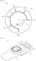
- FIG. 6 is a test device for testing a sample contained in a microfluidic device of a disc type
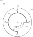
- FIG. 7 shows a microfluidic device of a disc type, which may be mounted in the test device of FIG. 6 .
- the test device 100 in accordance with another exemplary embodiment may test a sample contained in the microfluidic device 300 of a disc type.
- the sample is injected into the microfluidic device 300, and the microfluidic device 300 is settled on a tray 106 of the test device 100, the settled microfluidic device 300 is inserted to the inside of the main body 102 of the test device 100 with the tray 106.
- the test device 100 rotates the microfluidic device 300 about center C according to a predefined sequence, and the sample injected into the microfluidic device 300 is moved to the chambers 200 by a centrifugal force.
- Optical characteristic values of the sample may be measured in the inside of the main body 102 with the platform 320 inserted, and the concentration or diagnostic result of a measurement item determined by the data processor 130 may be displayed on the display 101.
- the microfluidic device 300 of a disc type may include the platform 320 and microfluidic structures formed on the platform 320
- the microfluidic structure may include a plurality of chambers that contain the sample or a reagent, and a channel that connects the chambers.
- the microfluidic structures are formed inside the platform 320, and in the exemplary embodiment, it is assumed that the platform 320 is formed of a transparent material, so the microfluidic structures formed inside the platform 320 are viewable when viewed from the top.
- the platform may be easy to be molded and have the surface formed of a biologically inactive material, such as plastic like PMMA, PDMS, PC, PP, PVA, PE, etc., glass, mica, silica, silicon wafer, etc.
- a biologically inactive material such as plastic like PMMA, PDMS, PC, PP, PVA, PE, etc., glass, mica, silica, silicon wafer, etc.
- exemplary embodiments are not limited thereto, and any material that is chemically and biologically stable and mechanically porous may be used as a material for the platform 320. Plus, the platform 320 may further have optical transparency to optically analyze the test results in the microfluidic device 300.
- the microfluidic device 300 of a disc type may move a substance within the microfluidic structure by a centrifugal force due to its rotation. While the platform 320 of a disc type is shown in the exemplary embodiment of FIG. 7 , the platform 320 may also have the shape of a complete circle, a sector, or a polygon if it is rotatable.
- the sample inlet hole 321 On the platform 320, the sample inlet hole 321, a sample providing chamber 323 for containing a sample injected through the sample inlet hole 321 and providing the sample to other chambers 200, the channel 322 for connecting the chambers 200 and the sample providing chamber 323 for the injected sample to be moved to the chambers 200.
- a microfluidic structure for centrifugation may further be included in the microfluidic device 300 as needed, and even a metering chamber for moving a fixed amount of sample to the chambers 200, a buffer chamber for containing a buffer fluid, etc., may further be included.
- the platform 320 may include multi-layered plates.
- an engraved structure that corresponds to a microfluidic structure, such as a chamber or a channel may be formed on the plane where the top and bottom plates are in contact, and a space for containing fluids and a passage for the fluids to flow through may be provided in the inside of the platform 320 by joining the two plates. Connection between the plates may be made by various methods, such as adhesion with an adhesive or double-sided adhesive tape, or ultrasound joining, laser welding, etc.
- test device 100 and microfluidic device 300 mounted on the test device 100 as described above are merely examples, and exemplary embodiments are not limited thereto.
- the microfluidic device 300 of the cartridge type or disc type but also cuvettes to contain the sample may be mounted on the test device 100.
- the chambers 200 are implemented in the cuvette type to be mounted on the test device 100. After the chamber 200 is mounted, optical characteristic values are measured, and a series of operations for measuring the concentration of total bilirubin present in the sample are performed as described above.
- FIG. 8 shows chamber arrangement for performing a sample test method, according to an exemplary embodiment
- FIG. 9 is a detailed flowchart illustrating the sample test method of FIG. 1 .
- the microfluidic device 300 of a cartridge type is used.
- the test device 100 may measure optical characteristic values of a target substance or interfering substance by irradiating light to the chambers 200 formed in the microfluidic device 300 and performing detection.
- the concentration of the target substance without use of a reagent
- optical characteristic values of the target substance and interfering substance may be measured in different chambers.
- a chamber 200a among the plurality of chambers 200 may be used as a target substance detection chamber, and another chamber 200b may be used as a blank chamber for measuring an optical characteristic value of an interfering substance.
- a sample injected into the sample inlet hole 321 is moved both to the target substance detection chamber 200a and to the blank chamber 200b, and thus respective optical characteristic values of the target substance and interfering substance may be measured by irradiating light to each of the target substance detection chamber 200a and the blank chamber 200b and performing detection.
- Operations 11 to 17 and 21 to 27 of FIG. 9 represent procedures of measuring optical characteristic values of the target substance and interfering substance in the sample test method of FIG. 1 , respectively.
- the optical characteristic value is a measurement of optical density.
- the light source 111 irradiates light of a main wavelength to the target substance detection chamber 200a, in operation 11.
- the target substance detection chamber 200a may contain a reagent for detecting the target substance and a sample, in which case an optical characteristic value due to a reaction between the reagent and the sample is measured. Alternatively, optical characteristics of the target substance itself contained in the sample may be measured without use of the reagent.
- the main wavelength refers to a wavelength specific to a substance to be detected, at which the substance has the highest optical density, or at which a product resulting from a reaction between the reagent and the substance has the highest optical density, or at which a product resulting from reaction catalyzed by the substance has the highest optical density.
- the detector 112 detects light transmitted through the target substance detection chamber 200a, in operation 12.
- the light source 111 then irradiates light of a sub-wavelength to the target substance detection chamber 200a, in operation 14.
- the sub-wavelength refers to a wavelength used to compensate the main wavelength optical density.
- the detector 112 detects light transmitted through the target substance detection chamber 200a, in operation 15.
- the main wavelength optical density is compensated using the obtained sub-wavelength optical density, in operation 17.
- the main wavelength optical density may be compensated by subtracting the sub-wavelength optical density from the main wavelength optical density.
- the light source 111 irradiates light of a main wavelength to the blank chamber 200b, in operation 21.
- the blank chamber 200b does not contain a reagent.
- the detector 112 detects light transmitted through the blank chamber 200b, in operation 22.
- the light source 111 then irradiates light of a sub-wavelength to the blank chamber 200b, in operation 24.
- the detector 112 detects light transmitted through the blank chamber 200b, in operation 25.
- the main wavelength optical density is compensated using the obtained sub-wavelength optical density, in operation 27.
- the main wavelength optical density may be compensated by subtracting the sub-wavelength optical density from the main wavelength optical density.
- the optical density of the target substance may then be compensated by subtracting the optical density of the interfering substance to which a fluctuation coefficient is applied, from the optical density of the target substance, in operation 30.
- the concentration of the target substance is then determined based on the compensated optical density of the target substance, in operation 40. With the compensated optical density from which interference of the interfering substance is eliminated, more accurate concentration may be determined.
- the data processor 130 may do compensation of the main wavelength optical density in operations 17, 27, and 30 and determination of the concentration of the target substance in operations 40.
- test method in accordance with an exemplary embodiment and operation of the test device for performing the method will now be described in more detail.
- reaction formula 1 L- ⁇ -glutamyl-3-carboxyl-4-nitroanilide + Glycylglycine GGT ------> L- ⁇ -glutamyl glycylglycine + 5-amino-2-nitro-benzoic acid, where, L- ⁇ -glutamyl-3-carboxyl-4-nitroanilide is a synthetic substrate, which is hydrolyzed by active GGT into L- ⁇ -glutamyl glycylglycine and 5-amino-2-nitro-benzoic acid.
- Glycylglycine is a substance to catalyze the hydrolysis of GGT.
- Reaction rate at which the synthetic substrate is hydrolyzed and metastasized by GGT may be measured by optically measuring the color of the hydrolysis derivative 5-amino-2-nitro-benzoic acid, and the GGT level may be determined from the reaction rate.
- the sample test method and test device in accordance with an exemplary embodiment compensates the optical characteristic value of GGT for interference caused by the interfering substances.
- the target substance detection chamber 200a contains a reagent for detecting GGT while the blank chamber 200b does not contain a reagent.
- the fact that the blank chamber 200b does not contain any reagent means that no reagent is contained to be used for detecting the interfering substance.
- the reagent for detecting GGT may include a synthetic substrate L- ⁇ -glutamyl glycylglycine and glycylglycine that catalyzes hydrolysis of the synthetic substrate, and further include stabilizers, buffers, surfactants, preservatives, antistripping agents, excipients, etc., as needed.
- Main and sub-wavelengths used to measure the GGT level using reaction formula 1, and main and sub-wavelengths used to be irradiated to the blank chamber 200b and to measure an influence of the interfering substance may be chosen in the range of 300nm to 900nm.
- Respective main and sub-wavelengths may be determined by experiments, theories, statistics, or simulations taking into account types of the target and interfering substances.
- both main wavelengths of light to be irradiated to the target substance detection chamber 200a and to the blank chamber 200b may be chosen to be 405nm.
- the sub-wavelengths to be irradiated to the target substance detection chamber 200a and the blank chamber 200b are chosen to be 450nm and 810nm, respectively.
- optical density obtained by irradiating light at 450nm to the target substance detection chamber 200a is subtracted from optical density obtained by irradiating light at 405nm.
- optical density obtained by irradiating light at 810nm to the blank chamber 200b is subtracted from optical density obtained by irradiating light at 405nm.
- the procedure of irradiating light of respective sub-wavelengths to the target substance detection chamber 200a and blank chamber 200b, detecting light transmitted through the respective chambers, and then subtracting the sub-wavelength optical density from the main wavelength optical density may be omitted.
- OD Eff is an effective optical density, indicating an optical density for which the interference of the interfering substance is compensated.
- OD tgt is an optical density measured for the target substance, e.g., GGT, indicating the main wavelength optical density compensated in operation 17 of FIG. 9
- OD int is an optical density of the interfering substance indicating the main wavelength optical density compensated in operation 27.
- OD tgt may be the main wavelength optical density of the target substance
- OD int may be the main wavelength optical density of the interfering substance
- F is an effect of the interfering substance, e.g., a fluctuation coefficient indicating a degree to which the interference of the interfering substance influences measurement of the concentration of the target substance, which may be determined by experiments, theories, statistics, or simulations.
- a fluctuation coefficient indicating a degree to which the interference of the interfering substance influences measurement of the concentration of the target substance, which may be determined by experiments, theories, statistics, or simulations.
- the fluctuation coefficient obtained by an experiment 1/70-1/50 may be applied.
- the concentration of the target substance is then determined based on the optical density for which the interference is compensated, in operation 40.
- a kinetic scheme may be applied for determination of the GGT level.
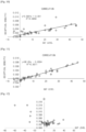
- FIG. 10 shows a graph representing correlations of measurements of optical density of GGT without compensation for interference of an interfering substance
- FIG. 11 shows a graph representing correlations of measurements of GGT level with compensation for interference of interfering substances based on a sample test method and test device, according to an exemplary embodiment. Both graphs show measurements in a low concentration (GGT level) region below 50 ⁇ L.
- Correlation is an index indicating a correlation of test results between a device as a standard and a device subject to performance determination, and accuracy may be indirectly determined for the correlation.
- the correlation may be represented by correlation coefficient R, in which case the nearer to 1 the absolute value of the correlation coefficient R, the higher the accuracy.
- the Y-axis represents optical densities for which interference of interfering substances is not compensated
- the X-axis represents GGT levels measured by the standard device. Referring to FIG. 10 , where interference of interfering substances are not compensated for, the correlation coefficient R was determined to be 0.82.
- the Y-axis represents optical densities for which interference of interfering substances is compensated for
- the X-axis represents GGT levels measured by the standard device.
- the correlation coefficient R is determined to be 0.98, so it is seen that the correlation has improved as compared to an occasion where interference of interfering substances is not compensated for.
- FIG. 12 shows a graph illustrating positive fallacy of measurements of optical density of GGT without compensation for interference of interfering substances
- FIG. 13 shows improvements in positive fallacy with compensation for interference of interfering substances based on a sample test method and test device, according to an exemplary embodiment.
- the target substance is GGT and the interfering substance is hemoglobin, bilirubin, or the like, present in a blood sample, especially, in a hemolytic blood sample, but they are not limited thereto.
- Any other substance than GGT among all the substances present in the bio-sample may be the target substance, while other substances than hemoglobin or bilirubin may be the interfering substances.
- the sample method and test device in accordance with the exemplary embodiments may be applied for other substances.
- bilirubin present in blood may be a measurement item, or act as an interfering substance that influences measurement of other substances.
- To eliminate the bilirubin interference it is required to accurately measure the concentration or an optical characteristic value of bilirubin present in the sample.
- a method for measuring the concentration and optical characteristic value of bilirubin present in a blood sample will be discussed first, and then a method for compensating for the bilirubin interference will be discussed.
- FIG. 14 is a flowchart illustrating the measurement of a concentration of bilirubin in a test method, according to an exemplary embodiment.
- optical characteristic values of a sample are measured for light of respective wavelengths in 400nm, 500nm, and 600nm bands, in operation 51.
- a range of a band spans approximately 100nm to distinguish effects of the wavelength on different substances.
- the sample contains bilirubin, and the optical characteristic values may be measured while the sample is contained in a chamber.
- Various optical characteristic values such as optical density, reflectivity, transmittance, etc., may be measured. For convenience of explanation, however, it is assumed in the following exemplary embodiments that optical density is to be measured.
- a final optical characteristic value is determined from the measured optical characteristic value, in operation 52.
- OD F represents a final optical density
- OD 400 represents an optical density at a wavelength in the 400nm band
- OD 500 represents an optical density at a wavelength in the 500nm band
- OD 600 represents an optical density at a wavelength in the 600nm band.
- Bilirubin mainly absorbs light of the 400nm band, but its optical characteristic values may be measured at wavelengths even in the 500nm and 600nm bands, and the concentration of bilirubin may be more accurately determined by eliminating optical characteristic values measured at wavelengths in the 500nm and 600nm bands from an optical characteristic value measured at a wavelength in the 400nm band.
- the concentration of total bilirubin present in the sample is determined, in operation 53.
- a calibration curve that represents relations between optical characteristic values and concentrations of a substance to be measured is pre-stored, and the concentration of the substance to be measured may be obtained by applying the optical characteristic value onto the calibration curve. Accordingly, even in this phase, the concentration of total bilirubin may be determined by applying the final optical density onto the pre-stored calibration curve for bilirubin.
- FIGS. 15 and 16 show operations of a test device measuring optical characteristic values of a sample contained in a chamber, according to an exemplary embodiment.
- the light source 111 irradiates light of wavelengths in the 400nm, 500nm, and 600nm bands to the chamber 200 to measure the concentration of bilirubin present in the sample S.
- the controller 120 may move the positions of the light source 111 and the detector 112 to positions corresponding to the chamber 200.
- the light source 111 may include a plurality of light source elements to simultaneously irradiate light of wavelengths in the 400nm, 500nm, and 600nm bands.
- the light source 111 may irradiate light of wavelengths in the 400nm, 500nm, and 600nm bands with time differences.
- the detector 112 detects light transmitted through the chamber 200, converts the detected light to an optical density corresponding to the light intensity, and outputs the optical density to the data processor 130.
- the data processor 130 may convert an electric signal output from the detector 112 to an optical density.
- the data processor 130 may then determine the concentration of total bilirubin by determining the final optical density with optical densities of respective wavelengths based on equation 2 and applying the final optical density onto the pre-stored calibration curve.
- the display 101 may display the determined concentration, and a series of operations to measure the optical density and display the determined concentration may be controlled by the controller 120.
- the measurer 110 measured optical densities for light of wavelengths at 450nm, 535nm, and 630nm, and that the results are as represented in the following table 1.
- the concentration of total bilirubin present in the sample may be determined to be 10.39mg/dL, and the controller 120 may provide the result for the user by displaying the result on the display 101.
- bilirubin present in the sample may act as an interfering substance in measuring one of electrolyte test items, a blood-chloride level.
- FIG. 17 shows a graph representing effects of bilirubin on measurements of the concentration of chloride.
- the concentration of chloride present in the sample is measured at different total bilirubin concentrations.
- a graph that represents differences (Bias) between actual concentration and measured concentration of chloride present in the sample at different concentrations of total bilirubin T-Bil is the graph shown in FIG. 10 .
- the graph shows that the higher the concentration of total bilirubin present in the sample, the larger the difference (Bias) between actual concentration and measured concentration of chloride. Accordingly, with a substance other than bilirubin as a measurement item, it is necessary to effectively eliminate the effect of bilirubin that influences the measurement result. A sample test method for eliminating bilirubin interference will now be described.
- FIG. 18 is a flowchart illustrating elimination of bilirubin interference in a sample test method, according to an exemplary embodiment.
- the concentration of total bilirubin measured by employing an optical scheme without adding a diluted solution to the sample or adding a separate reagent for measurement of bilirubin may be used to eliminate the bilirubin interference.
- respective optical characteristic values of a sample are measured for light having wavelengths in the 400nm, 500nm, and 600nm bands, in operation 61, and a final optical characteristic value may be determined from the measured optical characteristic values, in operation 62.
- the concentration of total bilirubin present in the sample is determined, in operation 63.
- the concentration of a measurement item may be determined at the same time as, or regardless of, or subsequently to determination of the concentration of total bilirubin. For this, optical characteristic values of the measurement item are measured in operation 64, and the concentration of the measurement item present in the sample may be determined using the measured optical characteristic values in operation 65.
- Wavelengths of light used to measure optical characteristic values of the measurement item may vary by the type of the measurement item, and at this time, a reagent may also be used to detect the measurement item.
- the calibration curve pre-stored for the measurement item may be used.
- a fluctuation coefficient is applied for the determined concentration of total bilirubin, and the result is added to or subtracted from the concentration of the measurement item, in operation 66.
- the concentration of the measurement item is the concentration determined in operation 65.
- C tgt refers to the concentration of the target substance without elimination of the bilirubin interference, F refers to a fluctuation coefficient, and C T_Bil refers to the concentration of total bilirubin determined in operation 63.
- the fluctuation coefficient is a value indicating a degree to which bilirubin influences a measurement of the target substance, e.g., the concentration of the target substance. It may vary depending on measurement scheme, type of the target substance, length of the light path, measurement time, etc., and a proper fluctuation coefficient may be set in advance for each case.
- the proper fluctuation coefficient may be set by experiments, statistics, theories, or simulations.
- the concentration of the target substance may be measured to be higher or less than its true concentration due to the bilirubin interference.
- the concentration of total bilirubin to which the fluctuation coefficient is applied F ⁇ C T_Bil
- the concentration of total bilirubin to which the fluctuation coefficient is applied F ⁇ C T_Bil
- the concentration of total bilirubin to which the fluctuation coefficient is applied F ⁇ C T_Bil
- the concentration of total bilirubin to which the fluctuation coefficient is applied is subtracted from the measured concentration of the target substance (C tgt ), thereby determining the effective concentration of the target substance (C Eff ).
- the sample test method in accordance with the exemplary embodiment eliminates the bilirubin interference based on the concentration.
- the bilirubin interference may also be eliminated based on optical characteristic values, as will be described below in detail.
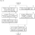
- FIG. 19 is a flowchart illustrating elimination of bilirubin interference in a sample test method, according to another exemplary embodiment.
- respective optical characteristic values of a sample are measured for light of wavelengths in the 400nm, 500nm, and 600nm bands, in operation 71, and a final optical characteristic value may be determined from the measured optical characteristic values, in operation 72.
- Those operations are the same as operations 51 and 52 of FIG. 14 , so the detailed description will be omitted herein.
- optical characteristic values of the sample for a measurement item are measured, in operation 73.
- Wavelengths of light used herein may vary by the type of the measurement item, and the optical characteristic values to be measured are assumed to be in the same type as that of the optical characteristic values measured in operation 71. In other words, if an optical density is measured in operation 71, an optical density is measured in operation 73 as well.
- An effective optical characteristic value of the measurement item is determined by adding or subtracting the final optical characteristic value to which the fluctuation coefficient is applied to or from an optical characteristic value of the measurement item, in operation 74.
- This procedure may be represented in equation 5, and in the present example, optical density (OD) is used as an optical characteristic value.
- OD Eff OD tgt ⁇ F ⁇ OD int , where OD Eff refers to an effective optical density of the target substance, resulting from elimination of the bilirubin interference.
- OD tgt refers to an optical density measured for the target substance, without elimination of bilirubin interference.
- the optical density is the one measured in operation 73.
- F is a fluctuation coefficient
- OD int is a final optical density of bilirubin that acts as an interfering substance, e.g., the final optical density OD F determined in operation 72.
- the fluctuation coefficient F used in equation 5 may be different from that used in equation 4.
- the bilirubin interference is eliminated based on concentrations in the exemplary embodiment of FIG. 18 , and on optical characteristic values in the exemplary embodiment of FIG. 19 . These two exemplary embodiments is distinguished by their respective phases in which the bilirubin interference is eliminated, and since degrees to which bilirubin influences the concentration of the target substance and the optical characteristic value measured for the target substance may be different, respective fluctuation coefficients in the two exemplary embodiments may be different as well.
- the optical density of the target substance may be measured to be higher or less than its true optical density due to the bilirubin interference. Therefore, taking into account such relations, it may be determined whether F ⁇ OD F is to be added or subtracted to or from the optical density measured for the target substance (OD M ).
- the concentration of the target substance from which the bilirubin interference is eliminated is determined using the effective optical characteristic value of the target substance, in operation 75.
- a calibration curve even for the target substance as a measurement item may be pre-stored, and the concentration of the target substance from which the bilirubin interference is eliminated may be determined by applying the effective optical density onto the pre-stored calibration curve.
- a reagent for measuring the concentration of the target substance is contained in the target substance detection chamber 200a.
- An optical characteristic value of bilirubin may be measured using the blank chamber 200b, or optical characteristic values of both the target substance and bilirubin may be measured using the target substance detection chamber 200a. It will be described below in more detail.
- a reaction between a reagent and a sample may be used to measure the concentration of a target substance.
- the target substance detection chamber 200a may contain the reagent and optical characteristic values of both the target substance and bilirubin may be measured in the same chamber 200a.
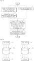
- FIG. 20 shows operations of measuring optical characteristics of a target substance and bilirubin in different chambers.
- the target substance detection chamber 200a for measuring the concentration of the target substance and the blank chamber 20b for measuring the concentration of bilirubin may be separately prepared, as shown in FIG. 20 .
- the light source 111 irradiates light of a proper wavelength for the target substance to the target substance detection chamber 200a, and the detector 112 detects light transmitted through the target substance detection chamber 200a and converts it to an optical characteristic value (OD tgt ) corresponding to the intensity of the detected light.
- the blank chamber 200b does not contain any reagent for measuring the concentration of bilirubin but plasma may be added in the blank chamber 200b.
- the light source 111 irradiates light of 400nm, 500nm, and 600nm bands, and the detector 112 detects light transmitted through the blank chamber 200b and convert them to optical characteristic values (OD 400 ,OD 500 ,OD 600 ) corresponding to the intensity of the detected light. It is also possible to further irradiate and detect light of a sub-wavelength in the 800nm band.
- optical characteristic values of the target substance and bilirubin may be measured at the same time, or with time differences, depending on the structure of the measurer 110.
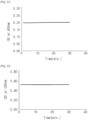
- FIG. 21 shows a graph representing an optical density measured by a test device at 450 nm, according to an exemplary embodiment
- FIG. 22 shows a graph representing an optical density measured by a test device at 535 nm, according to an exemplary embodiment
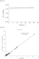
- FIG. 23 shows a graph representing an optical density measured by a test device at 630 nm, according to an exemplary embodiment.
- the concentration of bilirubin may be measured by optical measurement without use of a reagent.
- Results of measuring respective optical densities of a sample that does not react with a reagent at 450nm, 535nm, and 630nm show that the measurements of the optical densities change little in time but remain as stable values, as shown in FIGS. 21 to 23 .
- the optical density is said not to be restricted by time.
- FIG. 24 shows a graph representing correlations of test results by a test device, according to an exemplary embodiment.
- the Y-axis represents concentrations (mg/dL) of total bilirubin determined by the test device 100 in accordance with an exemplary embodiment
- the X-axis represents concentrations (mg/dL) of total bilirubin determined by a standard device.
- FIG. 25 is a table representing respective concentrations of chloride and total bilirubin measured by a test device of an exemplary embodiment and a standard device.
- samples A to G seven kinds of samples (samples A to G) including bilirubin and chloride were tested by each of the standard device and the test device 100 of the exemplary embodiment.
- Results of testing sample A show that the concentration of chloride was measured to be 89mg/dL by the standard device, and the concentration of chloride before compensation for bilirubin interference was measured to be 116mg/dL by the test device 100.
- the concentration of chloride before compensation for bilirubin interference corresponds to C tgt of equation 4.
- Results of testing sample B show that the concentration of chloride was measured to be 92mg/dL by the standard device, and the concentration of chloride before compensation for bilirubin interference was measured to be 104mg/dL by the test device 100.
- Results of testing sample C show that the concentration of chloride was measured to be 98mg/dL by the standard device, and the concentration of chloride before compensation for bilirubin interference was measured to be 110mg/dL by the test device 100.
- Results of testing sample D show that the concentration of chloride was measured to be 106mg/dL by the standard device, and the concentration of chloride before compensation for bilirubin interference was measured to be 112mg/dL by the test device 100.
- Results of testing sample E show that the concentration of chloride was measured to be 85mg/dL by the standard device, and the concentration of chloride before compensation for bilirubin interference was measured to be 91mg/dL by the test device 100.
- Results of testing sample F show that the concentration of chloride was measured to be 85mg/dL by the standard device, and the concentration of chloride before compensation for bilirubin interference was measured to be 91mg/dL by the test device 100.
- Results of testing sample G show that the concentration of chloride was measured to be 89mg/dL by the standard device, and the concentration of chloride before compensation for bilirubin interference was measured to be 98mg/dL by the test device 100.
- the concentrations of total bilirubin present in the respective samples were measured.
- the test device 100 performed a series of operations 61 to 63 of FIG. 18 , and the measured concentration of total bilirubin corresponds to C T_Bil of equation 4.
- the test device 100 determined the effective concentration of chloride C Eff by compensating for the bilirubin interference according to equation 4.
- the effective concentrations for samples A to G are 95mg/dL, 96mg/dL, 102mg/dL, 107mg/dL, 84mg/dL, 88mg/dL, and 95mg/dL, respectively.
- the difference (Bias) between the concentration measured by the standard device and the concentration C tgt measured by the test device 100 before compensation for the bilirubin interference is 30.30%, 13.10%, 12.20%, 5.60%, 7.20%, 7.20%, and 10.30% for samples A to G, respectively.
- the difference (Bias) between the concentration measured by the standard device and the concentration C Eff measured by the test device 100 after compensation for the bilirubin interference is 7.00%, 4.20%, 3.90%, 1.40%, 0.80%, 3.50%, and 6.70% for samples A to G, respectively. It is seen that compensation for the bilirubin interference in the test device 100 significantly reduces the gap in concentration from the concentration measured by the standard device.
- FIG. 26 shows a graph representing correlations of chloride concentrations before compensation for bilirubin interference
- FIG. 27 shows a graph representing correlations of chloride concentrations after compensation for bilirubin interference.
- the graphs shown in FIGS. 26 and 27 are produced based on experimental results represented in the table of FIG. 25 .
- the Y-axis of the graph of FIG. 26 represents chloride concentrations measured by the test device 100 before compensation for the bilirubin interference, e.g., C tgt
- the Y-axis of the graph of FIG. 27 represents chloride concentrations measured by the test device 100 after elimination of the bilirubin interference, e.g., C Eff .
- the X-axis of both graphs represents chloride concentrations measured by the standard device.
- correlations appear not to be good with a correlation coefficient being no more than 0.6738 before compensation for the bilirubin interference, as shown in FIG. 26 , but they appear to be better with an increased correlation coefficient being 0.9512 after compensation for the bilirubin interference, as shown in FIG. 27 .
- the chamber 200 in accordance with an exemplary embodiment has a structure in which the concentration of total bilirubin is more accurately measured or the bilirubin interference is more effectively eliminated. It will be described below in more detail.
- chambers 200a, 200c, 200d, 200e, 200f, 200g, 200h are only examples to implement the chamber 200 in accordance with an exemplary embodiment, e.g., the chamber 200 is considered to include all those chambers 200a, 200c, 200d, 200e, 200f, 200g, 200h.
- FIG. 28 shows a chamber structure, according to an exemplary embodiment
- FIG. 29 is a view of appearance of a microfluidic device of a cartridge type having the chamber structure of FIG. 28
- FIG. 30 is a cross-sectional view of the microfluidic device of FIG. 29 cut in AA' direction.
- a light path may influence the measurement results. For example, in measuring the concentration of bilirubin, a light path having the length of 3mm or less may help to accurately measure higher concentrations, and a light path having the length of 3mm or more may help to accurately measure lower concentrations.
- the chamber 200 may include a plurality of chambers 200c, 200d, 200e, 200f, 200g with respective light paths Path 1 , Path 2 , Path 3 , Path 4 , Path 5 of different lengths, as shown in FIG. 28 , in order to apply a light path of a proper length for a concentration range of bilirubin present in the sample.
- the chamber 200c having light path 1 (Path 1 ) is called chamber 1
- the chamber 200d having light path 2 (Path 2 ) is called chamber 2
- the chamber 200e having light path 3 (Path 3 ) is called chamber 3
- the chamber 200f having light path 4 (Path 4 ) is called chamber 4
- the chamber 200f having light path 5 (Path 5 ) is called chamber 5.
- the number of chambers in this exemplary embodiment is five, there may be more or less chambers than five as long as the chambers have different light paths in length.
- the plurality of chambers 200c, 200d, 200e, 200f, 200g with different light paths in length Path 1 , Path 2 , Path 3 , Path 4 , Path 5 may be formed on the platform 320 of the microfluidic device 300, and in a case that a substance other than bilirubin is a target substance, the target substance detection chamber 200a may further be formed to measure the concentration of the target substance.
- the length of the light path of the target substance detection chamber 200a may or may not be the same as that of one of the plurality of chambers 200c, 200d, 200e, 200f, 200g.
- the target substance detection chamber 200a may contain a reagent used to measure the concentration of the target substance. However, in the case the concentration of the target substance is measured only by optical measurement, the target substance detection chamber 200a may not contain the reagent.
- the plurality of chambers 200c, 200d, 200e, 200f, 200g do not contain a reagent for measuring the concentration of bilirubin.
- the bottom plate 320b of the respective chambers may be formed differently in terms of thickness, as shown in FIG. 30 .
- the thickness of the bottom plate 320b may be formed to be thicker, and for a chamber having a longer light path, the thickness of the bottom plate 320b may be formed to be thinner.
- the thickness of the bottom plate 320b for chamber 5 200g may be formed to be thickest, and the thickness of the bottom plate 320b for chamber 1 200a may be formed to be thinnest.
- FIG. 31 is a view of appearance of another microfluidic device having the chamber structure of FIG. 28 .
- the plurality of chambers 200c, 200d, 200e, 200f, 200g with different light paths in length Path 1 , Path 2 , Path 3 , Path 4 , Path 5 may be formed on the platform 320 of the microfluidic device 300, and in a case a substance other than bilirubin is a target substance, the target substance detection chamber 200a may further be formed to measure the concentration of the target substance.
- FIG. 32 shows a chamber structure, according to another exemplary embodiment
- FIG. 33 is a cross-sectional view of a microfluidic device having the chamber structure of FIG. 32 .
- a single chamber 200h it is also possible for a single chamber 200h to have different light paths Path 1 , Path 2 , Path 3 , Path 4 , Path 5 in length using steps 201, 202, 203, 204, and 205 having different depths.
- the microfluidic device or the test device may be miniaturized with the chamber 200h.
- steps may be formed on the floor of the chamber 200h.
- a lowest step 201 on the bottom of the chamber 200h forms the longest light path Path 1
- a highest step 205 forms the shortest light path Path 5 .
- the chamber 200h in the exemplary embodiment of FIG. 32 may be included in the microfluidic device 300 of both cartridge type and disc type.
- steps corresponding to the plurality of light paths may be formed on the bottom plate 320b that forms the single chamber 200h, as shown in FIG. 33 .
- the aforementioned chamber 200 not to be included in the microfluidic device 300 but to be implemented in the cuvette type such that the chamber 200 may be mounted directly on the test device 100.
- test device 100 for accurately measuring the concentration of bilirubin present in the sample or efficiently eliminating the bilirubin interference based on the chambers 200c, 200d, 200e, 200f, 200g, 200h will now be described.
- the light source 111 irradiates light to the respective light paths.
- the irradiated light may have a wavelength in the 400nm, 500nm, or 600nm band, or may have an arbitrary wavelength.
- the same wavelength of light is irradiated to the respective chambers 1, 2, 3, 4, and 5 200c, 200d, 200e, 200f, and 200g, and the detector 112 detects the respective light transmitted through them and converts them to respective optical characteristic values. It is assumed herein that the transmitted light is converted to optical density.
- the same wavelength of light is irradiated for the light paths 1 to 5 Path1 to Path5 formed on the chamber 200h, and the detector 112 detects light transmitted through the respective light paths and converts them to respective optical densities.
- the data processor 130 may measure linearity using the measured optical densities for the respective light paths, and select a light path to be used in measuring an optical density of bilirubin or an optical density of a measurement item based on the measurement result of linearity.
- FIGS. 34A and 34B show a schematic graph representing measurable results of linearity of light paths shown in FIG. 28 .
- the data processor 130 may select a longest light path within a range that meets linearity as a light path to be used for measurement of the optical density of bilirubin.
- the data processor 130 may select the longest light path 1.
- the data processor 130 may select the longest light path 3 among the light paths that satisfy linearity.
- the data processor 130 may determine the concentration of total bilirubin present in the sample using the optical densities measured in the 400nm, 500nm, and 600nm bands, equation 2, and the calibration curve, for the selected light path.
- the data processor 130 may determine the concentration of the target substance resulting from compensation for the bilirubin interference, using optical densities measured in the 400nm, 500nm, and 600nm bands, equation 2, the calibration curve for a measurement item, and equation 4, for the selected light path.
- the data processor 130 may determine the concentration of a measurement item resulting from compensation for the bilirubin interference, using optical densities measured in the 400nm, 500nm, and 600nm bands, equation 2, equation 5, and the calibration curve for the measurement item, for the selected light path.
- the aforementioned exemplary embodiments of the light path and chamber structure may, of course, be applied even in the case that the target substance or the interfering substance is not bilirubin.
- one of the plurality of light paths may be selected, and the GGT level may be determined using an optical density measured in the selected optical density.
- interference of an interfering substance present in the sample may be compensated for based on optical measurement without addition of any reagent for measuring the interfering substance.
- the interference of an interfering substance may be effectively compensated for, and even if the sample is used for tests without dilution, trustworthy test results may be obtained.
- the concentration of total bilirubin may be quantitatively measured, and the bilirubin interference may be effectively and accurately compensated for from a result of measuring other measurement item than bilirubin.
Landscapes
- Physics & Mathematics (AREA)
- Health & Medical Sciences (AREA)
- Life Sciences & Earth Sciences (AREA)
- Chemical & Material Sciences (AREA)
- Engineering & Computer Science (AREA)
- Immunology (AREA)
- Spectroscopy & Molecular Physics (AREA)
- Analytical Chemistry (AREA)
- Biochemistry (AREA)
- General Health & Medical Sciences (AREA)
- General Physics & Mathematics (AREA)
- Pathology (AREA)
- Biomedical Technology (AREA)
- Hematology (AREA)
- Ecology (AREA)
- Biophysics (AREA)
- Molecular Biology (AREA)
- Urology & Nephrology (AREA)
- Food Science & Technology (AREA)
- Medicinal Chemistry (AREA)
- Mathematical Physics (AREA)
- Theoretical Computer Science (AREA)
- Investigating Or Analysing Materials By Optical Means (AREA)
- Investigating Or Analysing Materials By The Use Of Chemical Reactions (AREA)
Description
- Apparatuses and methods consistent with exemplary embodiments relate to a sample test method, microfluidic device, and test device capable of in vitro diagnostics.
- In Vitro Diagnostics (IVD) may be performed through immunity tests, clinical chemistry tests, etc., on patient samples, and plays an important role in diagnosis and treatment on the patient's disease and determination of patient convalescence.
- IVD may be performed by measuring the concentration of a certain target substance present in the patient sample. Reactions between a reagent and the sample may be used for IVD. However, because other various substances in addition to the target substance are also present in the sample and act as interfering substances, reactions for detecting the target substance may be hampered or overreactions may occur.
-
Sung Hwa Lee et al. ("Test apparatus and target measurement method using the same", US2014/0193921 ) discloses a test apparatus and method for measuring concentration of a target by correcting for an impact of hemoglobin. -
Hisayuki Sagusa et al. ("Colorimetric method for liquid sampler including disturbing chromogens", US 4,263,512 ) discloses the addition of a color former to blood serum for coloring it, and for which measurements for specific components are determined based on the light absorbance caused by the coloring. -
James Samsoondar et al. ("Method and apparatus for measurement of blood substitutes", US 7,198,955 ) discloses a method whereby the concentration of a blood substitute in a serum or plasma specimen is identified and quantified. -
US 6 615 064 B1 relates to a non-invasive device and method for analyzing the concentration of blood components. - Accordingly, a need exists for development of a method for compensating for effects of the interfering substances present in the sample.
- Exemplary embodiments provide a sample test method and test device for efficiently and accurately compensating for interference of an interfering substance present in a sample with optical measurement without addition of a separate reagent for detecting the interfering substance.
- In accordance with an aspect of the invention, sample test method as defined with appended
independent claim 1 is provided. The sample test method includes - inter alia and as further defined with claim 1-measuring an optical characteristic value of a target substance present in a sample; measuring an optical characteristic value of an interfering substance present in the sample; and determining a concentration of the target substance for which interference of the interfering substance is compensated for based on the optical characteristic value of the interfering substance. - The compensating the optical characteristic value of the target substance may include applying a fluctuation coefficient to the optical characteristic value of the interfering substance to obtain an application result, and then subtracting or adding the application result from or to the optical characteristic value of the target substance.
- The measuring the optical characteristic value of the target substance includes measuring optical characteristic values of the target substance at a main wavelength and a sub-wavelength; and subtracting the optical characteristic value at the sub-wavelength from the optical characteristic value at the main wavelength.
- The main wavelength and the sub-wavelength may be each chosen from a range of 300nm to 900nm.
- The sample may include blood, and the target substance may include gamma-glutamyl transferase (GGT).
- The measuring the optical characteristic value of the interfering substance includes measuring optical characteristic values of the sample at a plurality of wavelengths, and determining a final optical characteristic value from the measured optical characteristic values, wherein the final optical characteristic value is the optical characteristic value for the interfering substance.
- The plurality of wavelengths may be chosen in 400nm band, 500nm band, and 600nm band, respectively.
- The determining the final optical characteristic value may include subtracting respective optical characteristic values measured at a wavelength in the 500nm band and at a wavelength in the 600nm band from an optical characteristic value measured at a wavelength in the 400nm band.
- The measuring an optical characteristic value of the interfering substance may include measuring an optical characteristic value of the sample at a wavelength in 800nm band.
- The determining the final optical characteristic value may include subtracting the optical characteristic value measured at a wavelength in the 800nm band from an optical characteristic value measured at a wavelength in the 400nm band, subtracting the optical characteristic value measured at a wavelength in the 800nm band from an optical characteristic value measured at a wavelength in the 500nm band, and subtracting the optical characteristic value measured at a wavelength in the 800nm band from an optical characteristic value measured at a wavelength in the 600nm band.
- The determining the final optical characteristic value may include subtracting a value resulting from the subtraction of the optical characteristic value measured at a wavelength in the 800nm band from the optical characteristic value measured at a wavelength in the 500nm band, and a value resulting from the subtraction of the optical characteristic value measured at a wavelength in the 800nm band from the optical characteristic value measured at a wavelength in the 600nm band from a value resulting from the subtraction of the optical characteristic value measured at a wavelength in the 800nm band from the optical characteristic value measured at a wavelength in the 400nm band.
- The interfering substance may include bilirubin.
- The determining the concentration of the target substance for which interference of the interfering substance is compensated for includes determining the concentration of the target substance based on the optical characteristic value of the target substance, determining the concentration of the interfering substance based on the optical characteristic value of the interfering substance, and compensating the concentration of the target substance using the concentration of the interfering substance.
- The measuring the optical characteristic value of the interfering substance may be done without the presence of a reagent for reacting with the interfering substance.
- The optical characteristic values may be representative of concentration of at least one of the target substance and the interfering substance, and the sample test method is performed using one or more processors.
- In accordance with a second aspect of the invention, a test device for in vitro diagnostics, as defined with appended
independent claim 6, is provided. The test device includes, inter alia and as further defined withclaim 6, a measurer configured to measure an optical characteristic value of a target substance present in a sample and an optical characteristic value of an interfering substance present in the sample; and a data processor configured to determine a concentration of the target substance for which interference of the interfering substance is compensated for based on the optical characteristic value of the interfering substance. - The data processor may be configured to apply a fluctuation coefficient to the optical characteristic value of the interfering substance to obtain an application result, and then subtract or add the application result from or to the optical characteristic value of the target substance.
- The measurer is configured to measure optical characteristic values of the target substance at a main wavelength and a sub-wavelength; and the data processor subtracts the optical characteristic value measured at the sub-wavelength from the optical characteristic value measured at the main wavelength.
- The main wavelength and the sub-wavelength may be each chosen from a range of 300nm to 900nm.
- The sample may include blood, and the target substance may include gamma-glutamyl transferase (GGT).
- The measurer is configured to measure optical characteristic values of the sample at a plurality of wavelengths, and the data processor determines a final optical characteristic value from the measured optical characteristic values of the sample, wherein the final optical characteristic value may be an optical characteristic value for the interfering substance.
- The plurality of wavelengths may be chosen in 400nm band, 500nm band, and 600nm band, respectively.
- The data processor may subtract respective optical characteristic values measured at a wavelength in the 500nm band and at a wavelength in the 600nm band from an optical characteristic value measured at a wavelength in the 400nm band.
- The measurer may be configured to measure an optical characteristic value of the sample at a wavelength in 800nm band.
- The data processor may be configured to determine the final optical characteristic value by subtracting the optical characteristic value measured at a wavelength in the 800nm band from an optical characteristic value measured at a wavelength in the 400nm band, subtracting the optical characteristic value measured at a wavelength in the 800nm band from an optical characteristic value measured at a wavelength in the 500nm band, and subtracting the optical characteristic value measured at a wavelength in the 800nm band from an optical characteristic value measured at a wavelength in the 600nm band.
- The data processor may determine the final optical characteristic value by subtracting a value resulting from the subtraction of the optical characteristic value measured at a wavelength in the 800nm band from the optical characteristic value measured at a wavelength in the 500nm band, and a value resulting from the subtraction of the optical characteristic value measured at a wavelength in the 800nm band from the optical characteristic value measured at a wavelength in the 600nm band from a value resulting from the subtraction of the optical characteristic value measured at a wavelength in the 800nm band from the optical characteristic value measured at a wavelength in the 400nm band.
- The interfering substance may include bilirubin.
- The data processor is configured to compensate the optical characteristic value of the target substance using the optical characteristic value of the interfering substance, and determine the concentration of the target substance based on the compensated optical characteristic value.
- The data processor is configured to determine the concentration of the target substance based on the optical characteristic value of the target substance, determine the concentration of the interfering substance based on the optical characteristic value of the interfering substance, and compensate the concentration of the target substance using the concentration of the interfering substance.
- Outside the scope of the appended claims, a microfluidic device is provided. The microfluidic device includes a platform formed with a sample inlet hole into which a sample is injected; a plurality of chambers each of the chambers having a different depth; and a channel connecting the sample inlet hole and the plurality of chambers.
- In accordance with an aspect of another exemplary embodiments, a test device is provided. The test device includes a measurer configured to measure optical characteristic values of a sample in a plurality of wavelength bands; and a data processor for configured to determine a final optical characteristic value from the measured optical characteristic values, and determine a concentration of bilirubin present in the sample based on the determined final optical characteristic value.
- The plurality of wavelength bands may include 400nm, 500nm, and 600nm bands.
- The data processor may be configured to subtract respective optical characteristic values measured at a wavelength in the 500nm band and at a wavelength in the 600nm band from an optical characteristic value measured at a wavelength in the 400nm band.
- The measurer may be configured to measure respective optical characteristic values of the sample a particular wavelength, for a plurality of light paths, each light path having a different length.
- The controller may be configured to select a light path from the light paths of different lengths based on the measured optical characteristic values.
- The controller may select a light path that satisfies linearity as related to the measured optical characteristic values of the plurality of light paths and has the longest light path length from among the measured optical characteristic values.
- The test device may receive a test platform, the test platform having plural chambers, each chamber having a different depth, to provide the plurality of light paths.
- According to the exemplary embodiments of the sample test method, test device, and chambers, interference of an interfering substance present in the sample may be compensated for based on optical measurement without addition of any reagent for measuring the interfering substance.
- Furthermore, even in a section where the target substance has a low concentration, the interference of an interfering substance may be effectively compensated for, and even if the sample is used for tests without dilution, trustworthy test results may be obtained.
- Moreover, the concentration of total bilirubin may be quantitatively measured, and the bilirubin interference may be effectively and accurately compensated for from a result of measuring other measurement item than bilirubin.
- In the following, the term "embodiment" does not necessarily mean an embodiment of the invention. The invention is limited only by the appended claims.
- The above and other aspects will become more apparent by describing in detail exemplary embodiments with reference to the attached drawings in which:
-
FIG. 1 is a flowchart illustrating a sample test method, according to an exemplary embodiment; -
FIG. 2 is a control block diagram of a test device, according to an exemplary embodiment; -
FIG. 3 is a view of appearance of an exemplary microfluidic device, according to an exemplary embodiment; -
FIG. 4 is an exploded view of a structure of a platform of the microfluidic device ofFIG. 3 ; -
FIG. 5 is a view of appearance of a test device for testing a sample contained in a microfluidic device of a cartridge type; -
FIG. 6 is a view of appearance of a test device for testing a sample contained in a microfluidic device of a disc type; -
FIG. 7 shows a microfluidic device of a disc type, which may be mounted on the test device ofFIG. 6 ; -
FIG. 8 shows chamber arrangement for performing a sample test method, according to an exemplary embodiment; -
FIG. 9 is a detailed flowchart illustrating the sample test method of the exemplary embodiment shown inFIG. 1 ; -
FIG. 10 shows a graph representing correlations of measurements of optical density of gamma-glutamyl transferase (GGT) without compensation for interference of an interfering substance; -
FIG. 11 shows a graph representing correlations of measurements of concentrations of GGT after compensation for interference of an interfering substance based on a sample test method and test device, according to an exemplary embodiment; -
FIG. 12 shows a graph representing positive fallacy of measurements of optical density of GGT without compensation for interference of an interfering substance; -
FIG. 13 shows improvements in positive fallacy after compensation for interference of an interfering substance based on a sample test method and test device, according to an exemplary embodiment; -
FIG. 14 is a flowchart illustrating the measurement of a concentration of bilirubin in a test method, according to an exemplary embodiment; -
FIGS. 15 and 16 show operations of a test device measuring optical characteristic values of a sample contained in a chamber, according to an exemplary embodiment; -
FIG. 17 shows a graph representing effects of bilirubin on measurements of the concentration of chloride; -
FIG. 18 is a flowchart illustrating elimination of bilirubin interference in a sample test method, according to an exemplary embodiment; -
FIG. 19 is a flowchart illustrating elimination of bilirubin interference in a sample test method, according to another exemplary embodiment; -
FIG. 20 shows operations of measuring optical characteristics of a target substance and bilirubin in different chambers; -
FIG. 21 shows a graph representing an optical density measured by a test device at 450 nm, according to an exemplary embodiment; -
FIG. 22 shows a graph representing an optical density measured by a test device at 535 nm, according to an exemplary embodiment; -
FIG. 23 shows a graph representing an optical density measured by a test device at 630 nm, according to an exemplary embodiment; -
FIG. 24 shows a graph representing correlations of test results by a test device, according to an exemplary embodiment; -
FIG. 25 is a table representing respective concentrations of chloride and bilirubin measured by a standard device and a test device in accordance with an exemplary embodiment; -
FIG. 26 shows a graph representing correlations of chloride concentrations before compensation for bilirubin interference; -
FIG. 27 shows a graph representing correlations of chloride concentrations after compensation for bilirubin interference; -
FIG. 28 shows a chamber structure, according to an exemplary embodiment; -
FIG. 29 is a view of appearance of a microfluidic device of a cartridge type having the chamber structure ofFIG. 28 ; -
FIG. 30 is a cross-sectional view of the microfluidic device ofFIG. 29 cut in AA' direction; -
FIG. 31 is a view of appearance of another microfluidic device having the chamber structure ofFIG. 28 ; -
FIG. 32 shows a chamber structure, according to another exemplary embodiment; -
FIG. 33 is a cross-sectional view of a microfluidic device having the chamber structure ofFIG. 32 ; and -
FIG. 34A and 34B show a schematic graph representing measurable results of linearity of light paths shown inFIG. 28 . - Throughout the drawings, like reference numerals will be understood to refer to like parts, components, and structures.
- Exemplary embodiments will now be described with reference to accompanying drawings.
- A sample test method, microfluidic device, and test device in accordance with exemplary embodiments may be applied for IVD that uses samples taken from a subject, and immunity tests, clinical chemistry tests, etc., may be performed for IVD.
- For example, a blood sample may be taken for IVD, and there are many different substances contained in the blood sample. For example, bilirubin contained in the blood is one of the constituents of bile, which is mainly produced in hemoglobin. The concentration of bilirubin increases when the patient has hepatitis, cirrhosis, liver cancer, biliary obstruction, etc., and the increase of bilirubin concentration in blood causes jaundice. Accordingly, bilirubin levels in blood may be an important index for a liver function test.
- IVD measurement items may also include measurement of substances other than bilirubin, such as creatinine measurement, electrolyte measurement, etc., for assessing a kidney function. Bilirubin in blood even influences measurements of other substances, which is called bilirubin interference.
- In a case that a measurement item is bilirubin or that bilirubin interference is to be eliminated from measurements of other measurement items, it is necessary to quantitatively and accurately measure the concentration of total bilirubin present in the sample, and to promptly perform measurement of the concentration of bilirubin or even elimination of its interference to fit the IVD characteristics in need of faster test results.
- In another example, gamma glutamyl transferase (GGT) is an enzyme widely distributed in many tissues, such as the kidneys, pancreas, prostate, liver, etc. GGT is activated to increase the in blood-GGT level in the body of a patient who suffers from obstructive jaundice, liver cancer, or alcoholic liver disease. Therefore, GGT may be included as a measurement item in the IVD measurement list, and the GGT level is measured to be used in diagnosis of obstructive jaundice, liver cancer, etc. However, accurate measurement of GGT level may be hampered by interference of other interfering substances present in the sample. For example, if the concentration of hemoglobin present in the sample is high or the sample is hemolytic, accurate measurement is disrupted significantly by the interfering substances.
- In an exemplary embodiment, a sample test method and test device may eliminate interference of the interfering substances other than a target substance present in the sample, with optical measurement without addition of a separate reagent in measuring the concentration of the target substance. The target substance refers to a substance subject to measurement among substances present in the sample, e.g., a substance that is a measurement item, and an interfering substance refers to a substance that influences the measurement of the concentration of the target substance among substances present in the sample other than the target substance.
-
FIG. 1 is a flowchart illustrating a sample test method, according to an exemplary embodiment. - Referring to
FIG. 1 , an optical characteristic value of a target substance is measured inoperation 10, and an optical characteristic value of an interfering substance is measured inoperation 20. The optical characteristic values may be measured while the sample is contained in a chamber or chambers. The optical characteristic values measured can include optical density indicating a degree to which a substance absorbs light, reflectivity indicating a degree to which a substance reflects light, transmittance indicating a degree to which light passes through a substance, or other various optical values. - The optical characteristic values of the target and interfering substances may be measured simultaneously or sequentially, depending on the structure of the test device as will be described below. As for the sequential measurement, there is no limitation on whether the optical characteristic value of the target substance is measured first or that of the interfering substance is measured first.
- The optical characteristic value of the target substance may be an optical characteristic value that appears due to a reaction between the sample and a particular reagent, or may be an optical characteristic value of the sample itself. In the former case, the particular reagent may include a substance that singularly or selectively reacts with the target substance, or a substance with which the reaction is catalyzed by the target substance, or a substance with which reaction is catalyzed by a substance activated by the target substance. In the latter case, optical characteristics of the target substance itself contained in the sample is measured without use of a reagent.
- The optical characteristic value of the interfering substance may be one of the sample itself. In other words, without use of a separate reagent for detecting the interfering substance, the optical characteristic value of the interfering substance may be measured by controlling the wavelength of light used for measurement of the optical characteristic value.
- The optical characteristic value of the target substance is compensated using the optical characteristic value of the interfering substance, in
operation 30. Specifically, the product of the optical characteristic value of the interfering substance multiplied by a predetermined coefficient may be subtracted from or added to the optical characteristic value of the target substance. The predetermined coefficient as used herein is assumed to be a fluctuation coefficient. - The concentration of the target substance is then estimated or calculated. Specifically, the concentration of the target substance is determined based on the compensated optical characteristic value of the target substance, in
operation 40. For example, the concentration of the target substance may be determined by applying the optical characteristic value onto a pre-stored calibration curve. The calibration curve may represent relations between optical characteristic values and concentrations of a target substance. A method for determining a concentration based on the optical characteristic value is divided into an end point-based method and a kinetic-based method. In the exemplary embodiment, it is assumed that a proper one of the end point-based method and the kinetic-based method is used. - While compensation is performed based on the optical characteristic value in the example of
FIG. 1 , concentration-based compensation is also possible. Specifically, compensation may also be made by determining the concentration of a target substance from the optical characteristic value of the target substance, determining the concentration of an interfering substance from the optical characteristic value of the interfering substance, and then adding or subtracting a value resulting from application of a fluctuation coefficient to the concentration of the interfering substance to or from the concentration of the target substance. - A test device in accordance with an exemplary embodiment will now be described. The test device may be used to perform tests according to the sample test method as described in connection with
FIG. 1 , so the description ofFIG. 1 may be equally applied to this test device. -
FIG. 2 is a control block diagram of a test device, according to an exemplary embodiment. - Referring to
FIG. 2 , atest device 100 in accordance with an exemplary embodiment may include ameasurer 110 for measuring an optical characteristic value at a particular wavelength, adata processor 130 for determining the concentration of a target substance contained in a sample based on measured optical characteristic values, and acontroller 120 for controlling overall operation of thetest device 100. The controller can be implemented in hardware such as a computing unit, integrated circuit, combination of hard and software, etc. - The
measurer 110 may include alight source 111 for producing and irradiating light, and adetector 112 for detecting light transmitted through or reflected from the sample. - For example, the
light source 111 may include a Light Emitting Diode (LED), or may be implemented with any other light source of a different type, such as semiconductor laser, He-Ne laser, halogen lamp, etc. Themeasurer 110 may further include an additional device, such as a filter for irradiating light of a particular wavelength. - Light of a desired wavelength in the band of 300nm to 800nm may be irradiated from the
light source 111, and a proper wavelength may be selected based on types of target and interfering substances and a scheme applied for concentration measurement. - The
detector 112 may detect light transmitted through the sample, and convert the detected light to an electric signal based on the intensity of the detected light. For this, thedetector 112 may include a light receiving element like a photo diode. It may also convert the electric signal to an optical characteristic value, such as optical density, transmittance, reflectivity, etc., and output the result to thedata processor 130. For this, thedetector 112 may further include an operation device like a microprocessor. Alternatively, thedetector 112 may output the electric signal, and thedata processor 130 may then convert the electric signal to an optical characteristic value, such as optical density and subsequently perform an operation for measurement of the concentration of a measurement item. - The
controller 120 may control general operations of thetest device 100. For example, it may control the wavelength of light irradiated from themeasurer 110, or control the position of themeasurer 110 to a position corresponding to a chamber that contains the sample, or control the rotation of the chamber if it is required to test the sample. - Furthermore, if the
data processor 130 measures the concentration of a measurement item or perform diagnosis on a particular disease based on a value output from thedetector 112, thecontroller 120 may control the results to be displayed, if any. - The
data processor 130 andcontroller 120 may include a memory to store a program associated with aforementioned or following operations, and a processor to run the program stored in the memory. It is possible for thedata processor 130 andcontroller 120 to each have at least one memory and processor, or to share the memory and processor. - Operation of the
test device 100 will be described in detail with reference to views of appearance of the microfluidic device andtest device 100 that contain a sample. -
FIG. 3 is a view of appearance of an exemplary microfluidic device, according to an exemplary embodiment, andFIG. 4 is an exploded view of a structure of a platform of the microfluidic device ofFIG. 3 . Referring toFIG. 3 , amicrofluidic device 300 in accordance with an exemplary embodiment may be implemented in a cartridge type, which includes ahousing 310 and aplatform 320 on which optical measurement is performed on a sample. - The
housing 310 allows the user to hold themicrofluidic device 300 while supporting theplatform 320. Thehousing 310 is easy to be molded, and may be formed of an chemically and biologically inactive material. - For example, various materials including plastic materials, such as acryl, e.g., polymethylmethacrylate (PMMA), polysiloxane, e.g., polydimethylsiloxane (PDMS), polycarbonate (PC), linear low density polyethylene (LLDPE), low density polyethylene (LDPE), medium density polyethylene (MDPE), high density polyethylene (HDPE), polyvinyl alcohol, very low density polyethylene (VLDPE), polypropylene (PP), acrylonitrile butadiene styrene (ABS), cycloolefin copolymer (COC), etc., glass, mica, silica, semiconductor wafer, etc., may be used as the material for the
housing 310. However, the material for thehousing 310 is not limited thereto. - The
platform 320 may be combined with thehousing 310 in such a way as to be connected to the bottom of thehousing 310, or to be inserted into a groove formed in thehousing 310. - A
sample inlet hole 321 is formed on theplatform 320 for a sample to be injected thereto. A sample to be provided for themicrofluidic device 300 may be a biosample, e.g., body fluids including blood, tissue fluids, lymph fluids, urine, saliva, marrow, or the like, and a target substance subject to concentration measurement may be electrolyte ions or enzymes present in the sample. - The user may use a tool, e.g., a pipet or a syringe to drop a sample into the
sample inlet hole 321 for tests. - The sample injected into the
sample inlet hole 321 flows into the inside of theplatform 320, and in this regard, although not shown, a filter is placed behind thesample inlet hole 321 to filter the injected sample. The filter may be a porous polymeric membrane formed of, e.g., PC, polyethersulfone (PES), polyethylene (PE), polysulfone (PS), polyaryl sulfone (PASF), etc. For example, if a blood sample is injected, blood corpuscle is filtered out but blood plasma or blood serum flows into the inside of theplatform 320 as the blood is passed through the filter. - Referring to
FIG. 4 , theplatform 320 may be formed in a structure in which threeplates top plate 320a, abottom plate 320b, and amiddle plate 320c, and the top andbottom plates chamber 200 from outside light. - The top and
bottom plates bottom plates - The
middle plate 320c of theplatform 320 may be formed of a porous sheet, such as cellulose to serve as a vent in itself, and the porous sheet may be made of a hydrophobic material or hydrophobic process is applied on the porous sheet in order not to influence the movement of the sample. - In the
platform 320, thesample inlet hole 321, a channel through which the injected sample is moved, and a plurality ofchambers 200. In a case that theplatform 320 is formed in a triple layered structure, atop hole 321a that constitutes thesample inlet hole 321 is formed on thetop plate 320a, andportions 325a corresponding to thechambers 200 may be processed to be transparent. - The
bottom plate 320b may also haveportions 325b corresponding to thechambers 200 processed transparently. Processing theportions chambers 200 or optical characteristics due to reactions that occur in thechambers 200. - Even in the
middle plate 320c, amiddle plate hole 321c that constitutes thesample inlet hole 321 is formed, and when the top, middle, andbottom plates middle plate holes sample inlet hole 321 of theplatform 320. - In the area of the
middle plate 320c,chambers 200 are formed in the opposite side to themiddle plate hole 321c, and thechambers 200 may be formed by trimming the portions corresponding to thechambers 200 into a certain shape like circle, square, etc., and then joining the top, middle, andbottom plates - Furthermore, the
channel 322 is formed on themiddle plate 320c to be 1µm to 500µm wide, in order for the sample injected into thesample inlet hole 321 to be moved to thechambers 200 by capillary attraction. However, the width of thechannel 322 is merely an example to be used in themicrofluidic device 300, and exemplary embodiments are not limited thereto. - Some of the plurality of
chambers 200 may contain respective reagents for the use of the chamber, or may be empty. For example, a chamber to be used to measure an optical characteristic value of an interfering substance may be empty, and a chamber to be used to detect a target substance may contain a reagent used for detection of the target substance in advance. If the concentration of the target substance is measured with optical measurement without use of a reagent, the chamber to be used to measure the target substance may not contain the reagent. - For example, as for containing a reagent beforehand, respective reagents may be contained in the form of dry reagents by applying them in
portions top plate 320a or thebottom plate 320b, drying them, and then joining the top, middle, andbottom plates hole 325c. However, exemplary embodiments of themicrofluidic device 300 are not limited thereto, and the reagents may also be contained in the liquid form or the bead form. - Once the sample is injected into the
sample inlet hole 321 of themicrofluidic device 300, the sample is moved to thechambers 200 along thechannel 322. Once the sample is moved to thechambers 200, thetest device 100 may measure the concentration of the target substance or interfering substance by irradiating light at a proper wavelength to each of thechambers 200 and detecting light transmitted through or reflected from the chamber. Operation of the test device for testing a sample contained in the cartridge typed microfluidic device will now be described. -
FIG. 5 is a test device for testing a sample contained in a microfluidic device of a cartridge type. - Referring to
FIG. 5 , a mountingunit 104 is formed in amain body 102 that constitutes appearance of thetest device 100. The mountingunit 104 is a space in which themicrofluidic device 300 that contains a sample is mounted. Themicrofluidic device 300 may be mounted in thetest device 100 after adoor 103 slides open. Specifically, theplatform 320 of themicrofluidic device 300 may be inserted into ainsertion groove 105 formed in the mountingunit 104. - After the mounting of the
microfluidic device 300 is completed, thedoor 103 is closed and then a test begins. Optical characteristic values may be measured in the inside of themain body 102 with theplatform 320 inserted, and the concentration or a diagnostic result of a measurement item determined by thedata processor 130 may be displayed on thedisplay 101. -
FIG. 6 is a test device for testing a sample contained in a microfluidic device of a disc type, andFIG. 7 shows a microfluidic device of a disc type, which may be mounted in the test device ofFIG. 6 . - Referring to
FIG. 6 , thetest device 100 in accordance with another exemplary embodiment may test a sample contained in themicrofluidic device 300 of a disc type. When the sample is injected into themicrofluidic device 300, and themicrofluidic device 300 is settled on atray 106 of thetest device 100, the settledmicrofluidic device 300 is inserted to the inside of themain body 102 of thetest device 100 with thetray 106. - Once the
microfluidic device 300 is inserted, thetest device 100 rotates themicrofluidic device 300 about center C according to a predefined sequence, and the sample injected into themicrofluidic device 300 is moved to thechambers 200 by a centrifugal force. - Optical characteristic values of the sample may be measured in the inside of the
main body 102 with theplatform 320 inserted, and the concentration or diagnostic result of a measurement item determined by thedata processor 130 may be displayed on thedisplay 101. - Referring to
FIG. 7 , themicrofluidic device 300 of a disc type may include theplatform 320 and microfluidic structures formed on theplatform 320
The microfluidic structure may include a plurality of chambers that contain the sample or a reagent, and a channel that connects the chambers. The microfluidic structures are formed inside theplatform 320, and in the exemplary embodiment, it is assumed that theplatform 320 is formed of a transparent material, so the microfluidic structures formed inside theplatform 320 are viewable when viewed from the top. - The platform may be easy to be molded and have the surface formed of a biologically inactive material, such as plastic like PMMA, PDMS, PC, PP, PVA, PE, etc., glass, mica, silica, silicon wafer, etc.
- However, exemplary embodiments are not limited thereto, and any material that is chemically and biologically stable and mechanically porous may be used as a material for the
platform 320. Plus, theplatform 320 may further have optical transparency to optically analyze the test results in themicrofluidic device 300. - The
microfluidic device 300 of a disc type may move a substance within the microfluidic structure by a centrifugal force due to its rotation. While theplatform 320 of a disc type is shown in the exemplary embodiment ofFIG. 7 , theplatform 320 may also have the shape of a complete circle, a sector, or a polygon if it is rotatable. - On the
platform 320, thesample inlet hole 321, asample providing chamber 323 for containing a sample injected through thesample inlet hole 321 and providing the sample toother chambers 200, thechannel 322 for connecting thechambers 200 and thesample providing chamber 323 for the injected sample to be moved to thechambers 200. - As for a blood sample, although not shown, a microfluidic structure for centrifugation may further be included in the
microfluidic device 300 as needed, and even a metering chamber for moving a fixed amount of sample to thechambers 200, a buffer chamber for containing a buffer fluid, etc., may further be included. - The
platform 320 may include multi-layered plates. For example, in a case that theplatform 320 includes two plates, top and bottom plates, an engraved structure that corresponds to a microfluidic structure, such as a chamber or a channel may be formed on the plane where the top and bottom plates are in contact, and a space for containing fluids and a passage for the fluids to flow through may be provided in the inside of theplatform 320 by joining the two plates. Connection between the plates may be made by various methods, such as adhesion with an adhesive or double-sided adhesive tape, or ultrasound joining, laser welding, etc. - The
test device 100 andmicrofluidic device 300 mounted on thetest device 100 as described above are merely examples, and exemplary embodiments are not limited thereto. Not only themicrofluidic device 300 of the cartridge type or disc type but also cuvettes to contain the sample may be mounted on thetest device 100. In this case, thechambers 200 are implemented in the cuvette type to be mounted on thetest device 100. After thechamber 200 is mounted, optical characteristic values are measured, and a series of operations for measuring the concentration of total bilirubin present in the sample are performed as described above. -
FIG. 8 shows chamber arrangement for performing a sample test method, according to an exemplary embodiment, andFIG. 9 is a detailed flowchart illustrating the sample test method ofFIG. 1 . In the exemplary embodiment ofFIG. 8 , it is assumed that themicrofluidic device 300 of a cartridge type is used. - As discussed above, the
test device 100 may measure optical characteristic values of a target substance or interfering substance by irradiating light to thechambers 200 formed in themicrofluidic device 300 and performing detection. In the case of measuring the concentration of the target substance without use of a reagent, it is also possible to measure optical characteristic values of the target substance and interfering substance in the same chamber. On the other hand, if a reagent is used to measure the concentration of the target substance and the reagent influences measurement of an optical characteristic value of the interfering substance, optical characteristic values of the target substance and interfering substance may be measured in different chambers. - For this, as shown in
FIG. 8 , achamber 200a among the plurality ofchambers 200 may be used as a target substance detection chamber, and anotherchamber 200b may be used as a blank chamber for measuring an optical characteristic value of an interfering substance. A sample injected into thesample inlet hole 321 is moved both to the targetsubstance detection chamber 200a and to theblank chamber 200b, and thus respective optical characteristic values of the target substance and interfering substance may be measured by irradiating light to each of the targetsubstance detection chamber 200a and theblank chamber 200b and performing detection. -
Operations 11 to 17 and 21 to 27 ofFIG. 9 represent procedures of measuring optical characteristic values of the target substance and interfering substance in the sample test method ofFIG. 1 , respectively. - First, the procedure of measuring an optical characteristic value of the target substance will now be described. In the exemplary embodiment, it is assumed that the optical characteristic value is a measurement of optical density.
- The
light source 111 irradiates light of a main wavelength to the targetsubstance detection chamber 200a, inoperation 11. The targetsubstance detection chamber 200a may contain a reagent for detecting the target substance and a sample, in which case an optical characteristic value due to a reaction between the reagent and the sample is measured. Alternatively, optical characteristics of the target substance itself contained in the sample may be measured without use of the reagent. The main wavelength refers to a wavelength specific to a substance to be detected, at which the substance has the highest optical density, or at which a product resulting from a reaction between the reagent and the substance has the highest optical density, or at which a product resulting from reaction catalyzed by the substance has the highest optical density. - The
detector 112 detects light transmitted through the targetsubstance detection chamber 200a, inoperation 12. - Based on electric signals output from the
detector 112, a main wavelength optical density of the target substance is obtained, inoperation 13. - The
light source 111 then irradiates light of a sub-wavelength to the targetsubstance detection chamber 200a, inoperation 14. The sub-wavelength refers to a wavelength used to compensate the main wavelength optical density. - The
detector 112 detects light transmitted through the targetsubstance detection chamber 200a, inoperation 15. - Based on electric signals output from the
detector 112, a sub-wavelength optical density of the target substance is obtained, inoperation 16. - The main wavelength optical density is compensated using the obtained sub-wavelength optical density, in
operation 17. For example, the main wavelength optical density may be compensated by subtracting the sub-wavelength optical density from the main wavelength optical density. - To measure an optical characteristic value of the interfering substance, the
light source 111 irradiates light of a main wavelength to theblank chamber 200b, inoperation 21. In this case, theblank chamber 200b does not contain a reagent. - The
detector 112 detects light transmitted through theblank chamber 200b, inoperation 22. - Based on electric signals output from the
detector 112, a main wavelength optical density of the interfering substance is obtained, inoperation 23. - The
light source 111 then irradiates light of a sub-wavelength to theblank chamber 200b, inoperation 24. - The
detector 112 detects light transmitted through theblank chamber 200b, inoperation 25. - Based on electric signals output from the
detector 112, a sub-wavelength optical density of the interfering substance is obtained, inoperation 26. - The main wavelength optical density is compensated using the obtained sub-wavelength optical density, in
operation 27. For example, the main wavelength optical density may be compensated by subtracting the sub-wavelength optical density from the main wavelength optical density. - The optical density of the target substance may then be compensated by subtracting the optical density of the interfering substance to which a fluctuation coefficient is applied, from the optical density of the target substance, in
operation 30. - The concentration of the target substance is then determined based on the compensated optical density of the target substance, in
operation 40. With the compensated optical density from which interference of the interfering substance is eliminated, more accurate concentration may be determined. - To perform tests in accordance with the aforementioned sample test method in the
test device 100, thedata processor 130 may do compensation of the main wavelength optical density inoperations operations 40. - The sample test method in accordance with an exemplary embodiment and operation of the test device for performing the method will now be described in more detail.
- As discussed above, in measuring a GGT level of a blood sample, other substances present in the blood, especially, in the hemolytic blood may act as interfering substances. An example of a method for measuring the GGT level may use the hydrolysis of a synthetic substrate as represented in the following reaction formula 1:
[Reaction Formula 1] L-γ-glutamyl-3-carboxyl-4-nitroanilide + Glycylglycine GGT ------> L- γ-glutamyl glycylglycine + 5-amino-2-nitro-benzoic acid,
where, L-γ-glutamyl-3-carboxyl-4-nitroanilide is a synthetic substrate, which is hydrolyzed by active GGT into L- γ-glutamyl glycylglycine and 5-amino-2-nitro-benzoic acid. Glycylglycine is a substance to catalyze the hydrolysis of GGT. Reaction rate at which the synthetic substrate is hydrolyzed and metastasized by GGT may be measured by optically measuring the color of the hydrolysis derivative 5-amino-2-nitro-benzoic acid, and the GGT level may be determined from the reaction rate. - However, due to interference of other interfering substances present in the sample, such as hemoglobin or bilirubin, the amount of hydrolysis derivative may appear to be abnormally high, hampering accuracy and correlation of the measured GGT level. Accordingly, the sample test method and test device in accordance with an exemplary embodiment compensates the optical characteristic value of GGT for interference caused by the interfering substances.
- Turning back to
FIG. 8 , the targetsubstance detection chamber 200a contains a reagent for detecting GGT while theblank chamber 200b does not contain a reagent. The fact that theblank chamber 200b does not contain any reagent means that no reagent is contained to be used for detecting the interfering substance. - The reagent for detecting GGT may include a synthetic substrate L- γ-glutamyl glycylglycine and glycylglycine that catalyzes hydrolysis of the synthetic substrate, and further include stabilizers, buffers, surfactants, preservatives, antistripping agents, excipients, etc., as needed.
- Main and sub-wavelengths used to measure the GGT level using
reaction formula 1, and main and sub-wavelengths used to be irradiated to theblank chamber 200b and to measure an influence of the interfering substance may be chosen in the range of 300nm to 900nm. - Respective main and sub-wavelengths may be determined by experiments, theories, statistics, or simulations taking into account types of the target and interfering substances. Specifically, both main wavelengths of light to be irradiated to the target
substance detection chamber 200a and to theblank chamber 200b may be chosen to be 405nm. The sub-wavelengths to be irradiated to the targetsubstance detection chamber 200a and theblank chamber 200b are chosen to be 450nm and 810nm, respectively. - To compensate the main wavelength optical density of GGT in
operation 17, optical density obtained by irradiating light at 450nm to the targetsubstance detection chamber 200a is subtracted from optical density obtained by irradiating light at 405nm. - In addition, to compensate the main wavelength optical density of the interfering substance in
operation 27, optical density obtained by irradiating light at 810nm to theblank chamber 200b is subtracted from optical density obtained by irradiating light at 405nm. - It is also possible to omit compensation of the main wavelength optical density based on the sub-wavelength optical density. In other words, the procedure of irradiating light of respective sub-wavelengths to the target
substance detection chamber 200a andblank chamber 200b, detecting light transmitted through the respective chambers, and then subtracting the sub-wavelength optical density from the main wavelength optical density may be omitted. - Optical density of the target substance may be compensated in
operation 30 as represented in the following equation 1:

where ODEff is an effective optical density, indicating an optical density for which the interference of the interfering substance is compensated. ODtgt is an optical density measured for the target substance, e.g., GGT, indicating the main wavelength optical density compensated inoperation 17 ofFIG. 9 , and ODint is an optical density of the interfering substance indicating the main wavelength optical density compensated inoperation 27. However, in a case that compensation of the main wavelength optical density based on the sub-wavelength optical density is omitted, it is natural that ODtgt may be the main wavelength optical density of the target substance, and ODint may be the main wavelength optical density of the interfering substance. - F is an effect of the interfering substance, e.g., a fluctuation coefficient indicating a degree to which the interference of the interfering substance influences measurement of the concentration of the target substance, which may be determined by experiments, theories, statistics, or simulations. As an example of the fluctuation coefficient obtained by an experiment, 1/70-1/50 may be applied.
- While a result from application of the fluctuation coefficient to the optical density of the interfering substance is eliminated from optical density measured for the target substance in
equation 1, it is possible to add the result to the optical density measured for the target substance based on the interference of the interfering substance that influences the optical density of the target substance. - The concentration of the target substance is then determined based on the optical density for which the interference is compensated, in
operation 40. A kinetic scheme may be applied for determination of the GGT level. -
FIG. 10 shows a graph representing correlations of measurements of optical density of GGT without compensation for interference of an interfering substance, andFIG. 11 shows a graph representing correlations of measurements of GGT level with compensation for interference of interfering substances based on a sample test method and test device, according to an exemplary embodiment. Both graphs show measurements in a low concentration (GGT level) region below 50µL. - Correlation is an index indicating a correlation of test results between a device as a standard and a device subject to performance determination, and accuracy may be indirectly determined for the correlation. The correlation may be represented by correlation coefficient R, in which case the nearer to 1 the absolute value of the correlation coefficient R, the higher the accuracy.
- In the graph of
FIG. 10 , the Y-axis represents optical densities for which interference of interfering substances is not compensated, and the X-axis represents GGT levels measured by the standard device. Referring toFIG. 10 , where interference of interfering substances are not compensated for, the correlation coefficient R was determined to be 0.82. - In the graph of
FIG. 11 , the Y-axis represents optical densities for which interference of interfering substances is compensated for, and the X-axis represents GGT levels measured by the standard device. Referring toFIG. 11 , where interference of interfering substances is compensated for by the sample test method and test device in accordance with an exemplary embodiment, the correlation coefficient R is determined to be 0.98, so it is seen that the correlation has improved as compared to an occasion where interference of interfering substances is not compensated for. -
FIG. 12 shows a graph illustrating positive fallacy of measurements of optical density of GGT without compensation for interference of interfering substances, andFIG. 13 shows improvements in positive fallacy with compensation for interference of interfering substances based on a sample test method and test device, according to an exemplary embodiment. - Measurements of optical densities of GGT without compensation for interference of interfering substances show that false positive appears in that optical densities in the negative concentration region are measured to be positive, as shown in
FIG. 12 . - On the other hand, measurements of optical densities of GGT with compensation for interference of interfering substances show that false positive is eliminated in that optical densities in the negative concentration region are measured to be negative, as shown in
FIG. 13 . - The aforementioned exemplary embodiments assume that the target substance is GGT and the interfering substance is hemoglobin, bilirubin, or the like, present in a blood sample, especially, in a hemolytic blood sample, but they are not limited thereto. Any other substance than GGT among all the substances present in the bio-sample may be the target substance, while other substances than hemoglobin or bilirubin may be the interfering substances. As long as proper main and sub-wavelengths are chosen depending on types of the target and interfering substances, the sample method and test device in accordance with the exemplary embodiments may be applied for other substances.
- As discussed above, bilirubin present in blood may be a measurement item, or act as an interfering substance that influences measurement of other substances. To eliminate the bilirubin interference, it is required to accurately measure the concentration or an optical characteristic value of bilirubin present in the sample. In the following description, a method for measuring the concentration and optical characteristic value of bilirubin present in a blood sample will be discussed first, and then a method for compensating for the bilirubin interference will be discussed.
-
FIG. 14 is a flowchart illustrating the measurement of a concentration of bilirubin in a test method, according to an exemplary embodiment. - Referring to
FIG. 14 , optical characteristic values of a sample are measured for light of respective wavelengths in 400nm, 500nm, and 600nm bands, inoperation 51.. One skilled in the art would understand that a range of a band spans approximately 100nm to distinguish effects of the wavelength on different substances. - It is assumed that the sample contains bilirubin, and the optical characteristic values may be measured while the sample is contained in a chamber. Various optical characteristic values, such as optical density, reflectivity, transmittance, etc., may be measured. For convenience of explanation, however, it is assumed in the following exemplary embodiments that optical density is to be measured.
- A final optical characteristic value is determined from the measured optical characteristic value, in
operation 52. - The final optical characteristic value may be determined as represented in equation 2:

- In
equation 2, ODF represents a final optical density, OD400 represents an optical density at a wavelength in the 400nm band, OD500 represents an optical density at a wavelength in the 500nm band, and OD600 represents an optical density at a wavelength in the 600nm band. - Bilirubin mainly absorbs light of the 400nm band, but its optical characteristic values may be measured at wavelengths even in the 500nm and 600nm bands, and the concentration of bilirubin may be more accurately determined by eliminating optical characteristic values measured at wavelengths in the 500nm and 600nm bands from an optical characteristic value measured at a wavelength in the 400nm band.
- It is also possible to perform compensation based on a sub-wavelength to further improve accuracy in the determined concentration. For this, an optical characteristic value may be measured even in the 800nm band of sub-wavelength, especially, at 810nm. After elimination of the optical characteristic value measured in the 800nm band from the respective optical characteristic values measured in the 400nm, 500nm, and 600nm bands, operation as represented in
equation 2 may be performed. In this case,equation 2 may be expressed as in equation 3:

- With the determined final optical characteristic value, the concentration of total bilirubin present in the sample is determined, in
operation 53. - To determine the concentration of bilirubin with the optical characteristic value, a calibration curve that represents relations between optical characteristic values and concentrations of a substance to be measured is pre-stored, and the concentration of the substance to be measured may be obtained by applying the optical characteristic value onto the calibration curve. Accordingly, even in this phase, the concentration of total bilirubin may be determined by applying the final optical density onto the pre-stored calibration curve for bilirubin.
- In case a reagent is used to measure the concentration of a substance, even the same type of reagent has different characteristics every time it is manufactured, and accordingly, coefficients of the calibration curve may vary. In accordance with an exemplary embodiment of the sample test method, however, because no reagent is used to measure the concentration of bilirubin, the same calibration coefficient may still be applied.
-
FIGS. 15 and 16 show operations of a test device measuring optical characteristic values of a sample contained in a chamber, according to an exemplary embodiment. - After the
microfluidic device 300 is mounted on thetest device 100, when a sample S is moved to thechamber 200 through thechannel 322, or when thechamber 200 of a cuvette type that contains the sample S is mounted on thetest device 100, thelight source 111 irradiates light of wavelengths in the 400nm, 500nm, and 600nm bands to thechamber 200 to measure the concentration of bilirubin present in the sample S. - In a case initial positions of the
light source 111 and thedetector 112 do not correspond to a position of thechamber 200, as shown inFIG. 15 , thecontroller 120 may move the positions of thelight source 111 and thedetector 112 to positions corresponding to thechamber 200. - The
light source 111 may include a plurality of light source elements to simultaneously irradiate light of wavelengths in the 400nm, 500nm, and 600nm bands. - On the other hand, as shown in
FIG. 16 , thelight source 111 may irradiate light of wavelengths in the 400nm, 500nm, and 600nm bands with time differences. - The
detector 112 detects light transmitted through thechamber 200, converts the detected light to an optical density corresponding to the light intensity, and outputs the optical density to thedata processor 130. Alternatively, thedata processor 130 may convert an electric signal output from thedetector 112 to an optical density. Thedata processor 130 may then determine the concentration of total bilirubin by determining the final optical density with optical densities of respective wavelengths based onequation 2 and applying the final optical density onto the pre-stored calibration curve. - The
display 101 may display the determined concentration, and a series of operations to measure the optical density and display the determined concentration may be controlled by thecontroller 120. - Operation of the
data processor 130 to determine the concentration of total bilirubin based on the measured optical characteristic values will now be described in detail. - For example, it is assumed that the
measurer 110 measured optical densities for light of wavelengths at 450nm, 535nm, and 630nm, and that the results are as represented in the following table 1.[Table 1] at 450nm at 535nm at 630nm Optical Density 0.103 0.072 0.062 - The
data processor 130 determines the final optical density ODF by applying a measured optical density intoequation 2, which becomes ODF = 0.103-0.072-0.062 = 0.09. - The final optical density ODF=0.09 is applied onto the calibration curve. For example, if the calibration curve is represented in equation y = -2824.5x3 + 189.48x2 + 88.078x + 3.1558, the final optical density 0.09 is applied to x, and accordingly, y=10.39. Accordingly, the concentration of total bilirubin present in the sample may be determined to be 10.39mg/dL, and the
controller 120 may provide the result for the user by displaying the result on thedisplay 101. - In the meantime, there is an occasion when the purpose of the sample test is not to measure the concentration of total bilirubin present in the sample. For example, bilirubin present in the sample may act as an interfering substance in measuring one of electrolyte test items, a blood-chloride level.
-
FIG. 17 shows a graph representing effects of bilirubin on measurements of the concentration of chloride. - The concentration of chloride present in the sample is measured at different total bilirubin concentrations. A graph that represents differences (Bias) between actual concentration and measured concentration of chloride present in the sample at different concentrations of total bilirubin T-Bil is the graph shown in
FIG. 10 . - Referring to
FIG. 17 , the graph shows that the higher the concentration of total bilirubin present in the sample, the larger the difference (Bias) between actual concentration and measured concentration of chloride. Accordingly, with a substance other than bilirubin as a measurement item, it is necessary to effectively eliminate the effect of bilirubin that influences the measurement result. A sample test method for eliminating bilirubin interference will now be described. -
FIG. 18 is a flowchart illustrating elimination of bilirubin interference in a sample test method, according to an exemplary embodiment. - In the sample test method in accordance with the exemplary embodiment, the concentration of total bilirubin measured by employing an optical scheme without adding a diluted solution to the sample or adding a separate reagent for measurement of bilirubin may be used to eliminate the bilirubin interference.
- Referring to
FIG. 18 , respective optical characteristic values of a sample are measured for light having wavelengths in the 400nm, 500nm, and 600nm bands, inoperation 61, and a final optical characteristic value may be determined from the measured optical characteristic values, inoperation 62. With application of the determined final optical characteristic value onto the calibration curve, the concentration of total bilirubin present in the sample is determined, in operation 63. Those operations are the same asoperations 51 to 53 ofFIG. 14 , so the detailed description will be omitted herein. - The concentration of a measurement item may be determined at the same time as, or regardless of, or subsequently to determination of the concentration of total bilirubin. For this, optical characteristic values of the measurement item are measured in
operation 64, and the concentration of the measurement item present in the sample may be determined using the measured optical characteristic values inoperation 65. - Wavelengths of light used to measure optical characteristic values of the measurement item may vary by the type of the measurement item, and at this time, a reagent may also be used to detect the measurement item. In determining the concentration of the measurement item using the measured optical characteristic values, the calibration curve pre-stored for the measurement item may be used.
- A fluctuation coefficient is applied for the determined concentration of total bilirubin, and the result is added to or subtracted from the concentration of the measurement item, in
operation 66. The concentration of the measurement item is the concentration determined inoperation 65. This procedure may be represented in equation 4:

where CEff refers to an effective concentration of the target substance, resulting from compensation for the bilirubin interference. Ctgt refers to the concentration of the target substance without elimination of the bilirubin interference, F refers to a fluctuation coefficient, and CT_Bil refers to the concentration of total bilirubin determined in operation 63. - The fluctuation coefficient is a value indicating a degree to which bilirubin influences a measurement of the target substance, e.g., the concentration of the target substance. It may vary depending on measurement scheme, type of the target substance, length of the light path, measurement time, etc., and a proper fluctuation coefficient may be set in advance for each case. The proper fluctuation coefficient may be set by experiments, statistics, theories, or simulations.
- The concentration of the target substance may be measured to be higher or less than its true concentration due to the bilirubin interference. In the former case, the concentration of total bilirubin to which the fluctuation coefficient is applied (F×CT_Bil) is added to the concentration of the target substance (Ctgt), and in the latter case, the concentration of total bilirubin to which the fluctuation coefficient is applied (F×CT_Bil) is subtracted from the measured concentration of the target substance (Ctgt), thereby determining the effective concentration of the target substance (CEff).
- The sample test method in accordance with the exemplary embodiment eliminates the bilirubin interference based on the concentration. However, as discussed above, the bilirubin interference may also be eliminated based on optical characteristic values, as will be described below in detail.
-
FIG. 19 is a flowchart illustrating elimination of bilirubin interference in a sample test method, according to another exemplary embodiment. - Referring to
FIG. 19 , respective optical characteristic values of a sample are measured for light of wavelengths in the 400nm, 500nm, and 600nm bands, inoperation 71, and a final optical characteristic value may be determined from the measured optical characteristic values, inoperation 72. Those operations are the same asoperations FIG. 14 , so the detailed description will be omitted herein. - At the same time as, or regardless of, or subsequently to measurement of the optical characteristic value of the sample for bilirubin in
operation 71, optical characteristic values of the sample for a measurement item are measured, inoperation 73. Wavelengths of light used herein may vary by the type of the measurement item, and the optical characteristic values to be measured are assumed to be in the same type as that of the optical characteristic values measured inoperation 71. In other words, if an optical density is measured inoperation 71, an optical density is measured inoperation 73 as well. - An effective optical characteristic value of the measurement item is determined by adding or subtracting the final optical characteristic value to which the fluctuation coefficient is applied to or from an optical characteristic value of the measurement item, in
operation 74. This procedure may be represented inequation 5, and in the present example, optical density (OD) is used as an optical characteristic value.
where ODEff refers to an effective optical density of the target substance, resulting from elimination of the bilirubin interference. ODtgt refers to an optical density measured for the target substance, without elimination of bilirubin interference. The optical density is the one measured inoperation 73. F is a fluctuation coefficient, and ODint is a final optical density of bilirubin that acts as an interfering substance, e.g., the final optical density ODF determined inoperation 72. - The fluctuation coefficient F used in
equation 5 may be different from that used inequation 4. The bilirubin interference is eliminated based on concentrations in the exemplary embodiment ofFIG. 18 , and on optical characteristic values in the exemplary embodiment ofFIG. 19 . These two exemplary embodiments is distinguished by their respective phases in which the bilirubin interference is eliminated, and since degrees to which bilirubin influences the concentration of the target substance and the optical characteristic value measured for the target substance may be different, respective fluctuation coefficients in the two exemplary embodiments may be different as well. - The optical density of the target substance may be measured to be higher or less than its true optical density due to the bilirubin interference. Therefore, taking into account such relations, it may be determined whether F×ODF is to be added or subtracted to or from the optical density measured for the target substance (ODM).
- The concentration of the target substance from which the bilirubin interference is eliminated is determined using the effective optical characteristic value of the target substance, in
operation 75. A calibration curve even for the target substance as a measurement item may be pre-stored, and the concentration of the target substance from which the bilirubin interference is eliminated may be determined by applying the effective optical density onto the pre-stored calibration curve. - It is natural to use the
aforementioned test device 100 andmicrofluidic device 300 in performing the sample test method in accordance with exemplary embodiments ofFIGS. 18 and19 . Turning back toFIG. 8 , a reagent for measuring the concentration of the target substance is contained in the targetsubstance detection chamber 200a. An optical characteristic value of bilirubin may be measured using theblank chamber 200b, or optical characteristic values of both the target substance and bilirubin may be measured using the targetsubstance detection chamber 200a. It will be described below in more detail. - Specifically, a reaction between a reagent and a sample may be used to measure the concentration of a target substance. In case that the reagent does not influence bilirubin, the target
substance detection chamber 200a may contain the reagent and optical characteristic values of both the target substance and bilirubin may be measured in thesame chamber 200a. -
FIG. 20 shows operations of measuring optical characteristics of a target substance and bilirubin in different chambers. - In a case a reagent for measuring the concentration of a target substance influences bilirubin, the target
substance detection chamber 200a for measuring the concentration of the target substance and the blank chamber 20b for measuring the concentration of bilirubin may be separately prepared, as shown inFIG. 20 . - With the reagent R used for detection of the target substance contained in the target
substance detection chamber 200a, when the sample S is injected into the targetsubstance detection chamber 200a, thelight source 111 irradiates light of a proper wavelength for the target substance to the targetsubstance detection chamber 200a, and thedetector 112 detects light transmitted through the targetsubstance detection chamber 200a and converts it to an optical characteristic value (ODtgt) corresponding to the intensity of the detected light. - The
blank chamber 200b does not contain any reagent for measuring the concentration of bilirubin but plasma may be added in theblank chamber 200b. When the sample S is injected into theblank chamber 200b, thelight source 111 irradiates light of 400nm, 500nm, and 600nm bands, and thedetector 112 detects light transmitted through theblank chamber 200b and convert them to optical characteristic values (OD 400,OD500,OD600) corresponding to the intensity of the detected light. It is also possible to further irradiate and detect light of a sub-wavelength in the 800nm band. - The optical characteristic values of the target substance and bilirubin may be measured at the same time, or with time differences, depending on the structure of the
measurer 110. -
FIG. 21 shows a graph representing an optical density measured by a test device at 450 nm, according to an exemplary embodiment,FIG. 22 shows a graph representing an optical density measured by a test device at 535 nm, according to an exemplary embodiment, andFIG. 23 shows a graph representing an optical density measured by a test device at 630 nm, according to an exemplary embodiment. - With the
test device 100, the concentration of bilirubin may be measured by optical measurement without use of a reagent. Results of measuring respective optical densities of a sample that does not react with a reagent at 450nm, 535nm, and 630nm show that the measurements of the optical densities change little in time but remain as stable values, as shown inFIGS. 21 to 23 . - Accordingly, since almost the same values may be obtained no matter what point of time the optical density is measured, the optical density is said not to be restricted by time.
-
FIG. 24 shows a graph representing correlations of test results by a test device, according to an exemplary embodiment. - In the graph of
FIG. 24 , the Y-axis represents concentrations (mg/dL) of total bilirubin determined by thetest device 100 in accordance with an exemplary embodiment, and the X-axis represents concentrations (mg/dL) of total bilirubin determined by a standard device. - Referring to
FIG. 24 , correlation coefficient R is determined to be 0.9967 (R2 =0.09934), which is very close to 1, meaning that accuracy of thetest device 100 in accordance with the exemplary embodiment is very high. -
FIG. 25 is a table representing respective concentrations of chloride and total bilirubin measured by a test device of an exemplary embodiment and a standard device. - In this regard, seven kinds of samples (samples A to G) including bilirubin and chloride were tested by each of the standard device and the
test device 100 of the exemplary embodiment. Results of testing sample A show that the concentration of chloride was measured to be 89mg/dL by the standard device, and the concentration of chloride before compensation for bilirubin interference was measured to be 116mg/dL by thetest device 100. The concentration of chloride before compensation for bilirubin interference corresponds to Ctgt ofequation 4. - Results of testing sample B show that the concentration of chloride was measured to be 92mg/dL by the standard device, and the concentration of chloride before compensation for bilirubin interference was measured to be 104mg/dL by the
test device 100. - Results of testing sample C show that the concentration of chloride was measured to be 98mg/dL by the standard device, and the concentration of chloride before compensation for bilirubin interference was measured to be 110mg/dL by the
test device 100. - Results of testing sample D show that the concentration of chloride was measured to be 106mg/dL by the standard device, and the concentration of chloride before compensation for bilirubin interference was measured to be 112mg/dL by the
test device 100. - Results of testing sample E show that the concentration of chloride was measured to be 85mg/dL by the standard device, and the concentration of chloride before compensation for bilirubin interference was measured to be 91mg/dL by the
test device 100. - Results of testing sample F show that the concentration of chloride was measured to be 85mg/dL by the standard device, and the concentration of chloride before compensation for bilirubin interference was measured to be 91mg/dL by the
test device 100. - Results of testing sample G show that the concentration of chloride was measured to be 89mg/dL by the standard device, and the concentration of chloride before compensation for bilirubin interference was measured to be 98mg/dL by the
test device 100. - In comparison of concentrations of chloride in the standard device and the test device (before compensation for the bilirubin interference), it is seen that there is a rather big difference between the concentrations and that the concentration of chloride is measured to be higher than its true concentration due to the bilirubin interference. Accordingly, it is seen that F×CT_Bil is to be subtracted from Ctgt in compensating for the bilirubin interference in accordance with
equation 4. - Referring again to
FIG. 25 , the concentrations of total bilirubin present in the respective samples were measured. For this, thetest device 100 performed a series ofoperations 61 to 63 ofFIG. 18 , and the measured concentration of total bilirubin corresponds to CT_Bil ofequation 4. - The
test device 100 determined the effective concentration of chloride CEff by compensating for the bilirubin interference according toequation 4. The effective concentrations for samples A to G are 95mg/dL, 96mg/dL, 102mg/dL, 107mg/dL, 84mg/dL, 88mg/dL, and 95mg/dL, respectively. - The difference (Bias) between the concentration measured by the standard device and the concentration Ctgt measured by the
test device 100 before compensation for the bilirubin interference is 30.30%, 13.10%, 12.20%, 5.60%, 7.20%, 7.20%, and 10.30% for samples A to G, respectively. - On the other hand, the difference (Bias) between the concentration measured by the standard device and the concentration CEff measured by the
test device 100 after compensation for the bilirubin interference is 7.00%, 4.20%, 3.90%, 1.40%, 0.80%, 3.50%, and 6.70% for samples A to G, respectively. It is seen that compensation for the bilirubin interference in thetest device 100 significantly reduces the gap in concentration from the concentration measured by the standard device. -
FIG. 26 shows a graph representing correlations of chloride concentrations before compensation for bilirubin interference, andFIG. 27 shows a graph representing correlations of chloride concentrations after compensation for bilirubin interference. - The graphs shown in
FIGS. 26 and 27 are produced based on experimental results represented in the table ofFIG. 25 . The Y-axis of the graph ofFIG. 26 represents chloride concentrations measured by thetest device 100 before compensation for the bilirubin interference, e.g., Ctgt, and the Y-axis of the graph ofFIG. 27 represents chloride concentrations measured by thetest device 100 after elimination of the bilirubin interference, e.g., CEff. The X-axis of both graphs represents chloride concentrations measured by the standard device. - It is seen that correlations appear not to be good with a correlation coefficient being no more than 0.6738 before compensation for the bilirubin interference, as shown in
FIG. 26 , but they appear to be better with an increased correlation coefficient being 0.9512 after compensation for the bilirubin interference, as shown inFIG. 27 . - In the meantime, the
chamber 200 in accordance with an exemplary embodiment has a structure in which the concentration of total bilirubin is more accurately measured or the bilirubin interference is more effectively eliminated. It will be described below in more detail. - In the following description,
chambers chamber 200 in accordance with an exemplary embodiment, e.g., thechamber 200 is considered to include all thosechambers -
FIG. 28 shows a chamber structure, according to an exemplary embodiment,FIG. 29 is a view of appearance of a microfluidic device of a cartridge type having the chamber structure ofFIG. 28 , andFIG. 30 is a cross-sectional view of the microfluidic device ofFIG. 29 cut in AA' direction. - In measuring optical characteristic values, a light path may influence the measurement results. For example, in measuring the concentration of bilirubin, a light path having the length of 3mm or less may help to accurately measure higher concentrations, and a light path having the length of 3mm or more may help to accurately measure lower concentrations.
- Accordingly, in an exemplary embodiment, the
chamber 200 may include a plurality ofchambers FIG. 28 , in order to apply a light path of a proper length for a concentration range of bilirubin present in the sample. - The
chamber 200c having light path 1 (Path1) is calledchamber 1, thechamber 200d having light path 2 (Path2) is calledchamber 2, thechamber 200e having light path 3 (Path3) is calledchamber 3, thechamber 200f having light path 4 (Path4) is calledchamber 4, and thechamber 200f having light path 5 (Path5) is calledchamber 5. - Although the number of chambers in this exemplary embodiment is five, there may be more or less chambers than five as long as the chambers have different light paths in length.
- As shown in
FIGS. 29 and30 , the plurality ofchambers platform 320 of themicrofluidic device 300, and in a case that a substance other than bilirubin is a target substance, the targetsubstance detection chamber 200a may further be formed to measure the concentration of the target substance. The length of the light path of the targetsubstance detection chamber 200a may or may not be the same as that of one of the plurality ofchambers - The target
substance detection chamber 200a may contain a reagent used to measure the concentration of the target substance. However, in the case the concentration of the target substance is measured only by optical measurement, the targetsubstance detection chamber 200a may not contain the reagent. The plurality ofchambers - For example, to form the plurality of
chambers bottom plate 320b of the respective chambers may be formed differently in terms of thickness, as shown inFIG. 30 . For a chamber having a shorter light path, the thickness of thebottom plate 320b may be formed to be thicker, and for a chamber having a longer light path, the thickness of thebottom plate 320b may be formed to be thinner. - In this exemplary embodiment, the thickness of the
bottom plate 320b forchamber 5 200g may be formed to be thickest, and the thickness of thebottom plate 320b forchamber 1 200a may be formed to be thinnest. -
FIG. 31 is a view of appearance of another microfluidic device having the chamber structure ofFIG. 28 . - Even in the case that the
microfluidic device 300 is implemented in a disc type, as shown inFIG. 31 , the plurality ofchambers platform 320 of themicrofluidic device 300, and in a case a substance other than bilirubin is a target substance, the targetsubstance detection chamber 200a may further be formed to measure the concentration of the target substance. -
FIG. 32 shows a chamber structure, according to another exemplary embodiment, andFIG. 33 is a cross-sectional view of a microfluidic device having the chamber structure ofFIG. 32 . - As shown in
FIG. 32 , it is also possible for asingle chamber 200h to have different light paths Path1, Path2, Path3, Path4, Path5 inlength using steps single chamber 200h, the microfluidic device or the test device may be miniaturized with thechamber 200h. - In order to form the light paths Path1, Path2, Path3, Path4, Path5 with different lengths within the
single chamber 200h, steps may be formed on the floor of thechamber 200h. Alowest step 201 on the bottom of thechamber 200h forms the longest light path Path1, and ahighest step 205 forms the shortest light path Path5. - The
chamber 200h in the exemplary embodiment ofFIG. 32 may be included in themicrofluidic device 300 of both cartridge type and disc type. - For example, in the case the
chamber 200h is included in themicrofluidic device 300 of a cartridge type, steps corresponding to the plurality of light paths may be formed on thebottom plate 320b that forms thesingle chamber 200h, as shown inFIG. 33 . - It is also possible for the
aforementioned chamber 200 not to be included in themicrofluidic device 300 but to be implemented in the cuvette type such that thechamber 200 may be mounted directly on thetest device 100. - Operations of the
test device 100 for accurately measuring the concentration of bilirubin present in the sample or efficiently eliminating the bilirubin interference based on thechambers - Once the plurality of
chambers single chamber 200h having different light paths, or themicrofluidic device 300 having them is mounted on thetest device 100, thelight source 111 irradiates light to the respective light paths. The irradiated light may have a wavelength in the 400nm, 500nm, or 600nm band, or may have an arbitrary wavelength. - Specifically, once the plurality of
chambers microfluidic device 300 having them is mounted on thetest device 100, the same wavelength of light is irradiated to therespective chambers detector 112 detects the respective light transmitted through them and converts them to respective optical characteristic values. It is assumed herein that the transmitted light is converted to optical density. - Alternatively, once a
single chamber 200h having many different light paths or themicrofluidic device 300 having thechamber 200h is mounted on thetest device 100, the same wavelength of light is irradiated for thelight paths 1 to 5 Path1 to Path5 formed on thechamber 200h, and thedetector 112 detects light transmitted through the respective light paths and converts them to respective optical densities. - The
data processor 130 may measure linearity using the measured optical densities for the respective light paths, and select a light path to be used in measuring an optical density of bilirubin or an optical density of a measurement item based on the measurement result of linearity. -
FIGS. 34A and 34B show a schematic graph representing measurable results of linearity of light paths shown inFIG. 28 . - In general, the longer the light path, the higher the confidence in the measured optical characteristic value, so the
data processor 130 may select a longest light path within a range that meets linearity as a light path to be used for measurement of the optical density of bilirubin. - For example, if all the optical densities for the
light paths 1 to 5 satisfy linearity, as shown inFIG. 34A , thedata processor 130 may select the longestlight path 1. - Alternatively, if only the optical densities for the
light paths light paths FIG. 34B , thedata processor 130 may select the longestlight path 3 among the light paths that satisfy linearity. - Furthermore, the
data processor 130 may determine the concentration of total bilirubin present in the sample using the optical densities measured in the 400nm, 500nm, and 600nm bands,equation 2, and the calibration curve, for the selected light path. - Or, the
data processor 130 may determine the concentration of the target substance resulting from compensation for the bilirubin interference, using optical densities measured in the 400nm, 500nm, and 600nm bands,equation 2, the calibration curve for a measurement item, andequation 4, for the selected light path. - Or, the
data processor 130 may determine the concentration of a measurement item resulting from compensation for the bilirubin interference, using optical densities measured in the 400nm, 500nm, and 600nm bands,equation 2,equation 5, and the calibration curve for the measurement item, for the selected light path. - The aforementioned exemplary embodiments of the light path and chamber structure may, of course, be applied even in the case that the target substance or the interfering substance is not bilirubin.
- For example, even in a case that the target substance is GGT, one of the plurality of light paths may be selected, and the GGT level may be determined using an optical density measured in the selected optical density.
- According to the exemplary embodiments of the sample test method, test device, and chambers, interference of an interfering substance present in the sample may be compensated for based on optical measurement without addition of any reagent for measuring the interfering substance.
- Furthermore, even in a section where the target substance has a low concentration, the interference of an interfering substance may be effectively compensated for, and even if the sample is used for tests without dilution, trustworthy test results may be obtained.
- Moreover, the concentration of total bilirubin may be quantitatively measured, and the bilirubin interference may be effectively and accurately compensated for from a result of measuring other measurement item than bilirubin.
- Several exemplary embodiments have been described, but a person of ordinary skill in the art will understand and appreciate that various modifications can be made without departing the scope of exemplary embodiments of the inventive concept. Thus, it will be apparent to those ordinary skilled in the art that the scope of technical protection is only defined by the following claims.
Claims (8)
- A sample test method for in vitro diagnostics comprising:measuring an optical characteristic value of a target substance present in a sample;measuring an optical characteristic value of an interfering substance present in the sample; anddetermining a concentration of the target substance for which interference of the interfering substance is compensated for based on the optical characteristic value of the interfering substance;wherein the measuring the optical characteristic value of the target substance comprises:measuring optical characteristic values of the target substance at a main wavelength and a sub-wavelength, andsubtracting the optical characteristic value at the sub-wavelength from the optical characteristic value at the main wavelength;wherein the measuring the optical characteristic value of the interfering substance comprises:measuring optical characteristic values of the sample at a plurality of wavelengths, anddetermining a final optical characteristic value from the measured optical characteristic values, wherein the final optical characteristic value is the optical characteristic value of the interfering substance;wherein the determining the concentration of the target substance for which interference of the interfering substance is compensated for comprises:determining the concentration of the target substance based on the optical characteristic value of the target substance,determining the concentration of the interfering substance based on the optical characteristic value of the interfering substance, andcompensating the concentration of the target substance using the concentration of the interfering substance.
- The sample test method of claim 1, wherein the compensating the concentration of the target substance comprises:
applying a fluctuation coefficient to the concentration of the interfering substance to obtain an application result, and then subtracting or adding the application result from or to the concentration of the target substance. - The sample test method of claim 1, wherein the sample includes blood,wherein the target substance includes gamma-glutamyl transferase (GGT), andwherein the interfering substance includes bilirubin.
- The sample test method of claim 1, wherein the measuring the optical characteristic value of the interfering substance is done without presence of a reagent for reacting with the interfering substance.
- The sample test method according to claim 1, wherein the optical characteristic values are representative of concentration amount of at least one of the target substance and the interfering substance, and
the sample test method is performed using one or more processors. - A test device (100) for in vitro diagnostics comprising:a measurer (110) configured to measure an optical characteristic value of a target substance present in a sample and a final optical characteristic value of an interfering substance present in the sample; anda data processor (130) configured to determine a concentration of the target substance for which interference of the interfering substance is compensated for based on the optical characteristic value of the interfering substance;wherein the measurer is configured to measure optical characteristic values of the interfering substance in the sample at a plurality of wavelengths; andwherein the data processor is configured to determine the final optical characteristic value for the interfering substance from the measured optical characteristic values of the sample;wherein the measurer is configured to measure optical characteristic values of the target substance at a main wavelength and a sub-wavelength; andwherein the data processor is configured to subtract the optical characteristic value measured at the sub-wavelength from the optical characteristic value measured at the main wavelength; andwherein the data processor is further configured to determine the concentration of the target substance based on the optical characteristic value of the target substance, determine the concentration of the interfering substance based on the optical characteristic value of the interfering substance, and compensate the concentration of the target substance using the concentration of the interfering substance.
- The test device of claim 6, wherein the data processor is configured to apply a fluctuation coefficient to the concentration of the interfering substance to obtain an application result, and then subtract or add the application result from or to the concentration of the target substance.
- The test device of claim 6,
wherein the interfering substance includes bilirubin.
Applications Claiming Priority (3)
| Application Number | Priority Date | Filing Date | Title |
|---|---|---|---|
| KR20140104285 | 2014-08-12 | ||
| KR1020140194091A KR102310652B1 (en) | 2014-08-12 | 2014-12-30 | Test method for sample, microfluidic device and test apparatus |
| PCT/KR2015/008397 WO2016024791A1 (en) | 2014-08-12 | 2015-08-11 | Sample test method, microfluidic device, and test device |
Publications (3)
| Publication Number | Publication Date |
|---|---|
| EP3180614A1 EP3180614A1 (en) | 2017-06-21 |
| EP3180614A4 EP3180614A4 (en) | 2018-02-21 |
| EP3180614B1 true EP3180614B1 (en) | 2023-11-29 |
Family
ID=55445500
Family Applications (1)
| Application Number | Title | Priority Date | Filing Date |
|---|---|---|---|
| EP15832169.5A Active EP3180614B1 (en) | 2014-08-12 | 2015-08-11 | Sample test method and test device |
Country Status (3)
| Country | Link |
|---|---|
| EP (1) | EP3180614B1 (en) |
| KR (1) | KR102310652B1 (en) |
| CN (1) | CN106662523A (en) |
Families Citing this family (4)
| Publication number | Priority date | Publication date | Assignee | Title |
|---|---|---|---|---|
| KR102453637B1 (en) * | 2018-03-29 | 2022-10-12 | 프리시젼바이오 주식회사 | Test apparatus, and method for contotolling thereof |
| CN110609002B (en) * | 2018-12-29 | 2024-05-31 | 深圳迈瑞生物医疗电子股份有限公司 | Interference detection method and sample analyzer |
| KR20220064861A (en) * | 2019-09-17 | 2022-05-19 | 노바 바이오메디컬 코포레이션 | Systems and Methods for Measuring Liver Enzyme Levels in Blood |
| KR102710849B1 (en) * | 2022-01-14 | 2024-09-26 | 재능대학교산학협력단 | Method for preventing measurement errors by eliminating hemoglobin and bilirubin interference effect |
Citations (3)
| Publication number | Priority date | Publication date | Assignee | Title |
|---|---|---|---|---|
| US6615064B1 (en) * | 1998-09-21 | 2003-09-02 | Essential Medical Devices, Inc. | Non-invasive blood component analyzer |
| US20080274554A1 (en) * | 2007-05-03 | 2008-11-06 | Roche Diagnostics Operations, Inc. | Oximeter for spectro-photometric in-vitro determination of hemoglobin derivatives |
| US20130084592A1 (en) * | 2011-10-04 | 2013-04-04 | Siemens Healthcare Diagnostics Inc. | Methods for correcting assay measurements |
Family Cites Families (8)
| Publication number | Priority date | Publication date | Assignee | Title |
|---|---|---|---|---|
| DE2847176C2 (en) * | 1977-10-31 | 1982-05-06 | Hitachi, Ltd., Tokyo | Method for the photometric determination of substances in blood serum |
| DE4427492A1 (en) * | 1994-08-03 | 1996-02-08 | Boehringer Mannheim Gmbh | Method for analyzing a medical sample while avoiding interference from hemolysis |
| DE19622089A1 (en) * | 1996-05-31 | 1997-12-04 | Boehringer Mannheim Gmbh | Method for the analysis of medical samples containing hemoglobin |
| US7198955B1 (en) * | 1997-03-03 | 2007-04-03 | Nir Diagnostics Inc. | Method and apparatus for measurement of blood substitutes |
| US6115673A (en) * | 1997-08-14 | 2000-09-05 | Instrumentation Metrics, Inc. | Method and apparatus for generating basis sets for use in spectroscopic analysis |
| WO2005027746A1 (en) * | 2003-09-22 | 2005-03-31 | Matsushita Electric Industrial Co., Ltd. | Method of measuring glucose concentration and glucose concentration measuring apparatus |
| JP5646323B2 (en) * | 2008-07-23 | 2014-12-24 | 日本化薬株式会社 | Method for measuring components in blood using hemolyzed whole blood and kit thereof |
| KR20140090506A (en) * | 2013-01-09 | 2014-07-17 | 삼성전자주식회사 | Test Apparatus and Target Measuring Method Using The Same |
-
2014
- 2014-12-30 KR KR1020140194091A patent/KR102310652B1/en active Active
-
2015
- 2015-08-11 CN CN201580043348.1A patent/CN106662523A/en active Pending
- 2015-08-11 EP EP15832169.5A patent/EP3180614B1/en active Active
Patent Citations (3)
| Publication number | Priority date | Publication date | Assignee | Title |
|---|---|---|---|---|
| US6615064B1 (en) * | 1998-09-21 | 2003-09-02 | Essential Medical Devices, Inc. | Non-invasive blood component analyzer |
| US20080274554A1 (en) * | 2007-05-03 | 2008-11-06 | Roche Diagnostics Operations, Inc. | Oximeter for spectro-photometric in-vitro determination of hemoglobin derivatives |
| US20130084592A1 (en) * | 2011-10-04 | 2013-04-04 | Siemens Healthcare Diagnostics Inc. | Methods for correcting assay measurements |
Non-Patent Citations (2)
| Title |
|---|
| MOROI Y ET AL: "Bilirubin in aqueous solution. Absorption spectrum, aqueous solubility, and dissociation constants", BULL. CHEM. SOC. JPN. 58 (5), 1 January 1985 (1985-01-01), pages 1426 - 1431, XP055517375, Retrieved from the Internet <URL:https://www.journal.csj.jp/doi/pdf/10.1246/bcsj.58.1426> [retrieved on 20181019] * |
| STEINKE J M AND SHEPHERD A P: "Effects of temperature on optical absorbance spectra of oxy-, carboxy-, and deoxyhemoglobin", CLINICAL CHEMISTRY, 1 July 1992 (1992-07-01), pages 1360, XP055517364, Retrieved from the Internet <URL:http://clinchem.aaccjnls.org/content/clinchem/38/7/1360.full.pdf> [retrieved on 20181019] * |
Also Published As
| Publication number | Publication date |
|---|---|
| CN106662523A (en) | 2017-05-10 |
| EP3180614A1 (en) | 2017-06-21 |
| KR102310652B1 (en) | 2021-10-12 |
| KR20160019841A (en) | 2016-02-22 |
| EP3180614A4 (en) | 2018-02-21 |
Similar Documents
| Publication | Publication Date | Title |
|---|---|---|
| US10126232B2 (en) | Sample test method, microfluidic device, and test device | |
| JP6757400B2 (en) | Component measuring device, component measuring method and component measuring program | |
| CA2109704C (en) | Analytical cartridge and system for detecting analytes | |
| EP1698883B1 (en) | Method of determining total hemoglobin concentration in undiluted and unhemolyzed whole blood | |
| EP2781907B1 (en) | Reflective absorbance measuring device, and integral apparatus for analyzing reflective absorbance and lateral flow | |
| KR102310652B1 (en) | Test method for sample, microfluidic device and test apparatus | |
| US9891174B2 (en) | Reactor, test apparatus, and test method | |
| EP3485459B1 (en) | System and method for optical whole blood hemolysis detection | |
| US20150147769A1 (en) | Method of testing sample and microfluidic device | |
| WO2007132903A1 (en) | Method for automatically identifying control liquid | |
| US20150160206A1 (en) | Microfluidic device and apparatus for testing the same | |
| WO2022056631A1 (en) | Rapid blood testing system | |
| US20170227407A1 (en) | Test apparatus and control method thereof | |
| US20170167985A1 (en) | Specimen analysis apparatus and method of analyzing specimen using the same | |
| EP4267940B1 (en) | Determining a difference measure indicative of a difference in concentration between two or more predetermined analytes in a liquid | |
| US12480873B2 (en) | Determining time response value of an analyte in a liquid | |
| US12339221B2 (en) | Component measurement device, component measurement device set, and information processing method | |
| KR20170082206A (en) | Fluid analysis cartridge and fluid analysis apparatus including the same | |
| KR102076524B1 (en) | Test apparatus of fluidic sample and test method of fluidic sample | |
| KR20190114187A (en) | Test apparatus, and method for contotolling thereof |
Legal Events
| Date | Code | Title | Description |
|---|---|---|---|
| STAA | Information on the status of an ep patent application or granted ep patent |
Free format text: STATUS: THE INTERNATIONAL PUBLICATION HAS BEEN MADE |
|
| PUAI | Public reference made under article 153(3) epc to a published international application that has entered the european phase |
Free format text: ORIGINAL CODE: 0009012 |
|
| STAA | Information on the status of an ep patent application or granted ep patent |
Free format text: STATUS: REQUEST FOR EXAMINATION WAS MADE |
|
| 17P | Request for examination filed |
Effective date: 20170103 |
|
| AK | Designated contracting states |
Kind code of ref document: A1 Designated state(s): AL AT BE BG CH CY CZ DE DK EE ES FI FR GB GR HR HU IE IS IT LI LT LU LV MC MK MT NL NO PL PT RO RS SE SI SK SM TR |
|
| AX | Request for extension of the european patent |
Extension state: BA ME |
|
| DAV | Request for validation of the european patent (deleted) | ||
| DAX | Request for extension of the european patent (deleted) | ||
| A4 | Supplementary search report drawn up and despatched |
Effective date: 20180123 |
|
| RIC1 | Information provided on ipc code assigned before grant |
Ipc: G01N 33/49 20060101ALI20180117BHEP Ipc: G01N 21/27 20060101ALI20180117BHEP Ipc: B01L 3/00 20060101ALI20180117BHEP Ipc: G01N 21/05 20060101ALI20180117BHEP Ipc: G01N 35/08 20060101ALI20180117BHEP Ipc: G01N 33/52 20060101AFI20180117BHEP Ipc: G01N 21/31 20060101ALN20180117BHEP |
|
| STAA | Information on the status of an ep patent application or granted ep patent |
Free format text: STATUS: EXAMINATION IS IN PROGRESS |
|
| 17Q | First examination report despatched |
Effective date: 20181026 |
|
| RAP1 | Party data changed (applicant data changed or rights of an application transferred) |
Owner name: PRECISION BIOSENSOR INC. |
|
| REG | Reference to a national code |
Ref country code: DE Ref legal event code: R079 Free format text: PREVIOUS MAIN CLASS: G01N0033520000 Ipc: G01N0021270000 Ref country code: DE Ref legal event code: R079 Ref document number: 602015086751 Country of ref document: DE Free format text: PREVIOUS MAIN CLASS: G01N0033520000 Ipc: G01N0021270000 |
|
| GRAP | Despatch of communication of intention to grant a patent |
Free format text: ORIGINAL CODE: EPIDOSNIGR1 |
|
| STAA | Information on the status of an ep patent application or granted ep patent |
Free format text: STATUS: GRANT OF PATENT IS INTENDED |
|
| RIC1 | Information provided on ipc code assigned before grant |
Ipc: B01L 3/00 20060101ALN20230523BHEP Ipc: G01N 33/49 20060101ALI20230523BHEP Ipc: G01N 21/31 20060101ALI20230523BHEP Ipc: G01N 33/52 20060101ALI20230523BHEP Ipc: G01N 21/05 20060101ALI20230523BHEP Ipc: G01N 21/27 20060101AFI20230523BHEP |
|
| INTG | Intention to grant announced |
Effective date: 20230616 |
|
| RIN1 | Information on inventor provided before grant (corrected) |
Inventor name: CHO, EUY HYUN Inventor name: SONG, KYUNG MI Inventor name: PARK, SUNG HA Inventor name: LEE, BEOM SEOK Inventor name: KIM, HA NA Inventor name: PARK, JOO HEE Inventor name: KIM, KUI HYUN Inventor name: PARK, SANG BUM |
|
| GRAS | Grant fee paid |
Free format text: ORIGINAL CODE: EPIDOSNIGR3 |
|
| GRAA | (expected) grant |
Free format text: ORIGINAL CODE: 0009210 |
|
| STAA | Information on the status of an ep patent application or granted ep patent |
Free format text: STATUS: THE PATENT HAS BEEN GRANTED |
|
| AK | Designated contracting states |
Kind code of ref document: B1 Designated state(s): AL AT BE BG CH CY CZ DE DK EE ES FI FR GB GR HR HU IE IS IT LI LT LU LV MC MK MT NL NO PL PT RO RS SE SI SK SM TR |
|
| REG | Reference to a national code |
Ref country code: GB Ref legal event code: FG4D |
|
| REG | Reference to a national code |
Ref country code: CH Ref legal event code: EP |
|
| REG | Reference to a national code |
Ref country code: DE Ref legal event code: R096 Ref document number: 602015086751 Country of ref document: DE |
|
| REG | Reference to a national code |
Ref country code: IE Ref legal event code: FG4D |
|
| REG | Reference to a national code |
Ref country code: LT Ref legal event code: MG9D |
|
| REG | Reference to a national code |
Ref country code: NL Ref legal event code: MP Effective date: 20231129 |
|
| PG25 | Lapsed in a contracting state [announced via postgrant information from national office to epo] |
Ref country code: GR Free format text: LAPSE BECAUSE OF FAILURE TO SUBMIT A TRANSLATION OF THE DESCRIPTION OR TO PAY THE FEE WITHIN THE PRESCRIBED TIME-LIMIT Effective date: 20240301 |
|
| PG25 | Lapsed in a contracting state [announced via postgrant information from national office to epo] |
Ref country code: IS Free format text: LAPSE BECAUSE OF FAILURE TO SUBMIT A TRANSLATION OF THE DESCRIPTION OR TO PAY THE FEE WITHIN THE PRESCRIBED TIME-LIMIT Effective date: 20240329 |
|
| PG25 | Lapsed in a contracting state [announced via postgrant information from national office to epo] |
Ref country code: LT Free format text: LAPSE BECAUSE OF FAILURE TO SUBMIT A TRANSLATION OF THE DESCRIPTION OR TO PAY THE FEE WITHIN THE PRESCRIBED TIME-LIMIT Effective date: 20231129 |
|
| PG25 | Lapsed in a contracting state [announced via postgrant information from national office to epo] |
Ref country code: ES Free format text: LAPSE BECAUSE OF FAILURE TO SUBMIT A TRANSLATION OF THE DESCRIPTION OR TO PAY THE FEE WITHIN THE PRESCRIBED TIME-LIMIT Effective date: 20231129 |
|
| PG25 | Lapsed in a contracting state [announced via postgrant information from national office to epo] |
Ref country code: LT Free format text: LAPSE BECAUSE OF FAILURE TO SUBMIT A TRANSLATION OF THE DESCRIPTION OR TO PAY THE FEE WITHIN THE PRESCRIBED TIME-LIMIT Effective date: 20231129 Ref country code: IS Free format text: LAPSE BECAUSE OF FAILURE TO SUBMIT A TRANSLATION OF THE DESCRIPTION OR TO PAY THE FEE WITHIN THE PRESCRIBED TIME-LIMIT Effective date: 20240329 Ref country code: GR Free format text: LAPSE BECAUSE OF FAILURE TO SUBMIT A TRANSLATION OF THE DESCRIPTION OR TO PAY THE FEE WITHIN THE PRESCRIBED TIME-LIMIT Effective date: 20240301 Ref country code: ES Free format text: LAPSE BECAUSE OF FAILURE TO SUBMIT A TRANSLATION OF THE DESCRIPTION OR TO PAY THE FEE WITHIN THE PRESCRIBED TIME-LIMIT Effective date: 20231129 Ref country code: BG Free format text: LAPSE BECAUSE OF FAILURE TO SUBMIT A TRANSLATION OF THE DESCRIPTION OR TO PAY THE FEE WITHIN THE PRESCRIBED TIME-LIMIT Effective date: 20240229 |
|
| REG | Reference to a national code |
Ref country code: AT Ref legal event code: MK05 Ref document number: 1636609 Country of ref document: AT Kind code of ref document: T Effective date: 20231129 |
|
| PG25 | Lapsed in a contracting state [announced via postgrant information from national office to epo] |
Ref country code: NL Free format text: LAPSE BECAUSE OF FAILURE TO SUBMIT A TRANSLATION OF THE DESCRIPTION OR TO PAY THE FEE WITHIN THE PRESCRIBED TIME-LIMIT Effective date: 20231129 |
|
| PG25 | Lapsed in a contracting state [announced via postgrant information from national office to epo] |
Ref country code: SE Free format text: LAPSE BECAUSE OF FAILURE TO SUBMIT A TRANSLATION OF THE DESCRIPTION OR TO PAY THE FEE WITHIN THE PRESCRIBED TIME-LIMIT Effective date: 20231129 Ref country code: RS Free format text: LAPSE BECAUSE OF FAILURE TO SUBMIT A TRANSLATION OF THE DESCRIPTION OR TO PAY THE FEE WITHIN THE PRESCRIBED TIME-LIMIT Effective date: 20231129 Ref country code: PL Free format text: LAPSE BECAUSE OF FAILURE TO SUBMIT A TRANSLATION OF THE DESCRIPTION OR TO PAY THE FEE WITHIN THE PRESCRIBED TIME-LIMIT Effective date: 20231129 Ref country code: NO Free format text: LAPSE BECAUSE OF FAILURE TO SUBMIT A TRANSLATION OF THE DESCRIPTION OR TO PAY THE FEE WITHIN THE PRESCRIBED TIME-LIMIT Effective date: 20240229 Ref country code: NL Free format text: LAPSE BECAUSE OF FAILURE TO SUBMIT A TRANSLATION OF THE DESCRIPTION OR TO PAY THE FEE WITHIN THE PRESCRIBED TIME-LIMIT Effective date: 20231129 Ref country code: LV Free format text: LAPSE BECAUSE OF FAILURE TO SUBMIT A TRANSLATION OF THE DESCRIPTION OR TO PAY THE FEE WITHIN THE PRESCRIBED TIME-LIMIT Effective date: 20231129 Ref country code: HR Free format text: LAPSE BECAUSE OF FAILURE TO SUBMIT A TRANSLATION OF THE DESCRIPTION OR TO PAY THE FEE WITHIN THE PRESCRIBED TIME-LIMIT Effective date: 20231129 |
|
| PG25 | Lapsed in a contracting state [announced via postgrant information from national office to epo] |
Ref country code: DK Free format text: LAPSE BECAUSE OF FAILURE TO SUBMIT A TRANSLATION OF THE DESCRIPTION OR TO PAY THE FEE WITHIN THE PRESCRIBED TIME-LIMIT Effective date: 20231129 |
|
| PG25 | Lapsed in a contracting state [announced via postgrant information from national office to epo] |
Ref country code: AT Free format text: LAPSE BECAUSE OF FAILURE TO SUBMIT A TRANSLATION OF THE DESCRIPTION OR TO PAY THE FEE WITHIN THE PRESCRIBED TIME-LIMIT Effective date: 20231129 Ref country code: CZ Free format text: LAPSE BECAUSE OF FAILURE TO SUBMIT A TRANSLATION OF THE DESCRIPTION OR TO PAY THE FEE WITHIN THE PRESCRIBED TIME-LIMIT Effective date: 20231129 |
|
| PG25 | Lapsed in a contracting state [announced via postgrant information from national office to epo] |
Ref country code: SK Free format text: LAPSE BECAUSE OF FAILURE TO SUBMIT A TRANSLATION OF THE DESCRIPTION OR TO PAY THE FEE WITHIN THE PRESCRIBED TIME-LIMIT Effective date: 20231129 |
|
| PG25 | Lapsed in a contracting state [announced via postgrant information from national office to epo] |
Ref country code: SM Free format text: LAPSE BECAUSE OF FAILURE TO SUBMIT A TRANSLATION OF THE DESCRIPTION OR TO PAY THE FEE WITHIN THE PRESCRIBED TIME-LIMIT Effective date: 20231129 Ref country code: SK Free format text: LAPSE BECAUSE OF FAILURE TO SUBMIT A TRANSLATION OF THE DESCRIPTION OR TO PAY THE FEE WITHIN THE PRESCRIBED TIME-LIMIT Effective date: 20231129 Ref country code: RO Free format text: LAPSE BECAUSE OF FAILURE TO SUBMIT A TRANSLATION OF THE DESCRIPTION OR TO PAY THE FEE WITHIN THE PRESCRIBED TIME-LIMIT Effective date: 20231129 Ref country code: EE Free format text: LAPSE BECAUSE OF FAILURE TO SUBMIT A TRANSLATION OF THE DESCRIPTION OR TO PAY THE FEE WITHIN THE PRESCRIBED TIME-LIMIT Effective date: 20231129 Ref country code: DK Free format text: LAPSE BECAUSE OF FAILURE TO SUBMIT A TRANSLATION OF THE DESCRIPTION OR TO PAY THE FEE WITHIN THE PRESCRIBED TIME-LIMIT Effective date: 20231129 Ref country code: CZ Free format text: LAPSE BECAUSE OF FAILURE TO SUBMIT A TRANSLATION OF THE DESCRIPTION OR TO PAY THE FEE WITHIN THE PRESCRIBED TIME-LIMIT Effective date: 20231129 Ref country code: AT Free format text: LAPSE BECAUSE OF FAILURE TO SUBMIT A TRANSLATION OF THE DESCRIPTION OR TO PAY THE FEE WITHIN THE PRESCRIBED TIME-LIMIT Effective date: 20231129 |
|
| PG25 | Lapsed in a contracting state [announced via postgrant information from national office to epo] |
Ref country code: PT Free format text: LAPSE BECAUSE OF FAILURE TO SUBMIT A TRANSLATION OF THE DESCRIPTION OR TO PAY THE FEE WITHIN THE PRESCRIBED TIME-LIMIT Effective date: 20240401 |
|
| PG25 | Lapsed in a contracting state [announced via postgrant information from national office to epo] |
Ref country code: PT Free format text: LAPSE BECAUSE OF FAILURE TO SUBMIT A TRANSLATION OF THE DESCRIPTION OR TO PAY THE FEE WITHIN THE PRESCRIBED TIME-LIMIT Effective date: 20240401 |
|
| REG | Reference to a national code |
Ref country code: DE Ref legal event code: R097 Ref document number: 602015086751 Country of ref document: DE |
|
| PLBE | No opposition filed within time limit |
Free format text: ORIGINAL CODE: 0009261 |
|
| STAA | Information on the status of an ep patent application or granted ep patent |
Free format text: STATUS: NO OPPOSITION FILED WITHIN TIME LIMIT |
|
| PG25 | Lapsed in a contracting state [announced via postgrant information from national office to epo] |
Ref country code: SI Free format text: LAPSE BECAUSE OF FAILURE TO SUBMIT A TRANSLATION OF THE DESCRIPTION OR TO PAY THE FEE WITHIN THE PRESCRIBED TIME-LIMIT Effective date: 20231129 |
|
| PG25 | Lapsed in a contracting state [announced via postgrant information from national office to epo] |
Ref country code: SI Free format text: LAPSE BECAUSE OF FAILURE TO SUBMIT A TRANSLATION OF THE DESCRIPTION OR TO PAY THE FEE WITHIN THE PRESCRIBED TIME-LIMIT Effective date: 20231129 |
|
| 26N | No opposition filed |
Effective date: 20240830 |
|
| REG | Reference to a national code |
Ref country code: CH Ref legal event code: PL |
|
| PG25 | Lapsed in a contracting state [announced via postgrant information from national office to epo] |
Ref country code: LU Free format text: LAPSE BECAUSE OF NON-PAYMENT OF DUE FEES Effective date: 20240811 |
|
| PG25 | Lapsed in a contracting state [announced via postgrant information from national office to epo] |
Ref country code: MC Free format text: LAPSE BECAUSE OF FAILURE TO SUBMIT A TRANSLATION OF THE DESCRIPTION OR TO PAY THE FEE WITHIN THE PRESCRIBED TIME-LIMIT Effective date: 20231129 Ref country code: CH Free format text: LAPSE BECAUSE OF NON-PAYMENT OF DUE FEES Effective date: 20240831 |
|
| REG | Reference to a national code |
Ref country code: BE Ref legal event code: MM Effective date: 20240831 |
|
| PG25 | Lapsed in a contracting state [announced via postgrant information from national office to epo] |
Ref country code: BE Free format text: LAPSE BECAUSE OF NON-PAYMENT OF DUE FEES Effective date: 20240831 |
|
| PG25 | Lapsed in a contracting state [announced via postgrant information from national office to epo] |
Ref country code: FR Free format text: LAPSE BECAUSE OF NON-PAYMENT OF DUE FEES Effective date: 20240831 |
|
| PG25 | Lapsed in a contracting state [announced via postgrant information from national office to epo] |
Ref country code: IE Free format text: LAPSE BECAUSE OF NON-PAYMENT OF DUE FEES Effective date: 20240811 |
|
| PG25 | Lapsed in a contracting state [announced via postgrant information from national office to epo] |
Ref country code: FI Free format text: LAPSE BECAUSE OF FAILURE TO SUBMIT A TRANSLATION OF THE DESCRIPTION OR TO PAY THE FEE WITHIN THE PRESCRIBED TIME-LIMIT Effective date: 20231129 |
|
| PGFP | Annual fee paid to national office [announced via postgrant information from national office to epo] |
Ref country code: DE Payment date: 20250730 Year of fee payment: 11 |
|
| PGFP | Annual fee paid to national office [announced via postgrant information from national office to epo] |
Ref country code: IT Payment date: 20250825 Year of fee payment: 11 |
|
| PGFP | Annual fee paid to national office [announced via postgrant information from national office to epo] |
Ref country code: GB Payment date: 20250731 Year of fee payment: 11 |
|
| PG25 | Lapsed in a contracting state [announced via postgrant information from national office to epo] |
Ref country code: CY Free format text: LAPSE BECAUSE OF FAILURE TO SUBMIT A TRANSLATION OF THE DESCRIPTION OR TO PAY THE FEE WITHIN THE PRESCRIBED TIME-LIMIT; INVALID AB INITIO Effective date: 20150811 |
|
| PG25 | Lapsed in a contracting state [announced via postgrant information from national office to epo] |
Ref country code: HU Free format text: LAPSE BECAUSE OF FAILURE TO SUBMIT A TRANSLATION OF THE DESCRIPTION OR TO PAY THE FEE WITHIN THE PRESCRIBED TIME-LIMIT; INVALID AB INITIO Effective date: 20150811 |