EP3180244B1 - System and method for controlling a pressure field around an aircraft in flight - Google Patents
System and method for controlling a pressure field around an aircraft in flight Download PDFInfo
- Publication number
- EP3180244B1 EP3180244B1 EP15766673.6A EP15766673A EP3180244B1 EP 3180244 B1 EP3180244 B1 EP 3180244B1 EP 15766673 A EP15766673 A EP 15766673A EP 3180244 B1 EP3180244 B1 EP 3180244B1
- Authority
- EP
- European Patent Office
- Prior art keywords
- controller
- pressure
- aircraft
- pressure field
- movable component
- Prior art date
- Legal status (The legal status is an assumption and is not a legal conclusion. Google has not performed a legal analysis and makes no representation as to the accuracy of the status listed.)
- Active
Links
- 238000000034 method Methods 0.000 title claims description 15
- 230000003466 anti-cipated effect Effects 0.000 claims description 47
- 238000013500 data storage Methods 0.000 claims description 24
- RZVHIXYEVGDQDX-UHFFFAOYSA-N 9,10-anthraquinone Chemical compound C1=CC=C2C(=O)C3=CC=CC=C3C(=O)C2=C1 RZVHIXYEVGDQDX-UHFFFAOYSA-N 0.000 claims description 6
- 230000035939 shock Effects 0.000 claims description 2
- 230000000694 effects Effects 0.000 description 25
- 230000006835 compression Effects 0.000 description 14
- 238000007906 compression Methods 0.000 description 14
- 238000004891 communication Methods 0.000 description 11
- 238000013461 design Methods 0.000 description 8
- 230000009471 action Effects 0.000 description 5
- 238000012544 monitoring process Methods 0.000 description 5
- 230000008878 coupling Effects 0.000 description 4
- 238000010168 coupling process Methods 0.000 description 4
- 238000005859 coupling reaction Methods 0.000 description 4
- 230000003292 diminished effect Effects 0.000 description 4
- 230000003993 interaction Effects 0.000 description 4
- 230000003287 optical effect Effects 0.000 description 4
- 230000005540 biological transmission Effects 0.000 description 3
- 230000003068 static effect Effects 0.000 description 3
- 230000008859 change Effects 0.000 description 2
- 238000010586 diagram Methods 0.000 description 2
- 238000012552 review Methods 0.000 description 2
- 238000009825 accumulation Methods 0.000 description 1
- 230000002411 adverse Effects 0.000 description 1
- 230000004075 alteration Effects 0.000 description 1
- 230000015572 biosynthetic process Effects 0.000 description 1
- 238000009530 blood pressure measurement Methods 0.000 description 1
- 238000004364 calculation method Methods 0.000 description 1
- 238000004590 computer program Methods 0.000 description 1
- 230000001419 dependent effect Effects 0.000 description 1
- 239000012530 fluid Substances 0.000 description 1
- 239000000446 fuel Substances 0.000 description 1
- 230000006870 function Effects 0.000 description 1
- 230000037361 pathway Effects 0.000 description 1
- 230000000644 propagated effect Effects 0.000 description 1
- 230000009467 reduction Effects 0.000 description 1
- 238000005070 sampling Methods 0.000 description 1
- 238000012360 testing method Methods 0.000 description 1
Images


Classifications
-
- B—PERFORMING OPERATIONS; TRANSPORTING
- B64—AIRCRAFT; AVIATION; COSMONAUTICS
- B64C—AEROPLANES; HELICOPTERS
- B64C13/00—Control systems or transmitting systems for actuating flying-control surfaces, lift-increasing flaps, air brakes, or spoilers
- B64C13/02—Initiating means
- B64C13/16—Initiating means actuated automatically, e.g. responsive to gust detectors
-
- B—PERFORMING OPERATIONS; TRANSPORTING
- B64—AIRCRAFT; AVIATION; COSMONAUTICS
- B64C—AEROPLANES; HELICOPTERS
- B64C23/00—Influencing air flow over aircraft surfaces, not otherwise provided for
- B64C23/04—Influencing air flow over aircraft surfaces, not otherwise provided for by generating shock waves
-
- B—PERFORMING OPERATIONS; TRANSPORTING
- B64—AIRCRAFT; AVIATION; COSMONAUTICS
- B64C—AEROPLANES; HELICOPTERS
- B64C30/00—Supersonic type aircraft
-
- B—PERFORMING OPERATIONS; TRANSPORTING
- B64—AIRCRAFT; AVIATION; COSMONAUTICS
- B64D—EQUIPMENT FOR FITTING IN OR TO AIRCRAFT; FLIGHT SUITS; PARACHUTES; ARRANGEMENT OR MOUNTING OF POWER PLANTS OR PROPULSION TRANSMISSIONS IN AIRCRAFT
- B64D31/00—Power plant control systems; Arrangement of power plant control systems in aircraft
- B64D31/02—Initiating means
- B64D31/06—Initiating means actuated automatically
-
- B—PERFORMING OPERATIONS; TRANSPORTING
- B64—AIRCRAFT; AVIATION; COSMONAUTICS
- B64D—EQUIPMENT FOR FITTING IN OR TO AIRCRAFT; FLIGHT SUITS; PARACHUTES; ARRANGEMENT OR MOUNTING OF POWER PLANTS OR PROPULSION TRANSMISSIONS IN AIRCRAFT
- B64D33/00—Arrangement in aircraft of power plant parts or auxiliaries not otherwise provided for
- B64D33/02—Arrangement in aircraft of power plant parts or auxiliaries not otherwise provided for of combustion air intakes
-
- F—MECHANICAL ENGINEERING; LIGHTING; HEATING; WEAPONS; BLASTING
- F02—COMBUSTION ENGINES; HOT-GAS OR COMBUSTION-PRODUCT ENGINE PLANTS
- F02C—GAS-TURBINE PLANTS; AIR INTAKES FOR JET-PROPULSION PLANTS; CONTROLLING FUEL SUPPLY IN AIR-BREATHING JET-PROPULSION PLANTS
- F02C9/00—Controlling gas-turbine plants; Controlling fuel supply in air- breathing jet-propulsion plants
- F02C9/26—Control of fuel supply
- F02C9/28—Regulating systems responsive to plant or ambient parameters, e.g. temperature, pressure, rotor speed
-
- G—PHYSICS
- G01—MEASURING; TESTING
- G01L—MEASURING FORCE, STRESS, TORQUE, WORK, MECHANICAL POWER, MECHANICAL EFFICIENCY, OR FLUID PRESSURE
- G01L19/00—Details of, or accessories for, apparatus for measuring steady or quasi-steady pressure of a fluent medium insofar as such details or accessories are not special to particular types of pressure gauges
- G01L19/0061—Electrical connection means
- G01L19/0084—Electrical connection means to the outside of the housing
-
- G—PHYSICS
- G01—MEASURING; TESTING
- G01L—MEASURING FORCE, STRESS, TORQUE, WORK, MECHANICAL POWER, MECHANICAL EFFICIENCY, OR FLUID PRESSURE
- G01L19/00—Details of, or accessories for, apparatus for measuring steady or quasi-steady pressure of a fluent medium insofar as such details or accessories are not special to particular types of pressure gauges
- G01L19/14—Housings
Definitions
- the present invention generally relates to aircraft and more particularly relates to systems and methods for controlling a pressure field around an aircraft in flight.
- a quiet supersonic aircraft is a supersonic aircraft that will be able to comply with applicable governmental restrictions on the magnitude of sonic booms for flight over land or over other restricted areas, when such restrictions are set.
- Quiet supersonic aircraft will be designed to comply with such governmental restrictions when flying at a predetermined supersonic speed (e.g., Mach 1.7) and at predetermined atmospheric conditions (e.g., standard atmospheric conditions) and at predetermined operating conditions (e.g., throttle settings, angle of attack).
- predetermined supersonic speed e.g., Mach 1.7
- predetermined atmospheric conditions e.g., standard atmospheric conditions
- predetermined operating conditions e.g., throttle settings, angle of attack
- a quiet supersonic aircraft will have a pressure field around the aircraft that is substantially free from steep pressure gradients.
- the phrase "steep pressure gradient” refers to a relatively large change in pressure over a relatively short distance.
- a pressure field free of steep pressure gradients, when propagated to the ground, can give rise to a sonic boom having a magnitude that falls below governmentally imposed limits. Any deviation from the predetermined supersonic speed or from the predetermined atmospheric conditions or from the predetermined operating conditions may give rise to a steep pressure gradient in the pressure field. If a steep pressure gradient were to form in the pressure field around the aircraft during supersonic flight, this could have an undesirable effect on the magnitude of the sonic boom that propagates to the ground.
- the propulsion system of a supersonic aircraft interacts aerodynamically with the airframe and with the pressure field around the supersonic aircraft. For example, the flow of air ingested by the propulsion system's inlet, the cycle at which the propulsion system's engine is operated, or the exhaust plume expelled by the propulsion system's nozzle will interact with the airflow around the supersonic aircraft's airframe.
- a quiet supersonic aircraft is designed such that when the propulsion system is operating at its design condition, the effect of the propulsion system on the pressure field will not give rise to a relatively steep gradient in the pressure field.
- a reference to the design condition of a propulsion system refers to the predetermined engine cycle, the predetermined Mach speed, the predetermined atmospheric conditions, and the predetermined throttle settings that the engine will be operating at when the aircraft is operating at its design condition.
- the propulsion system can cause a relatively steep gradient to form in the pressure field around the aircraft. This is undesirable.
- US 2010/0258678 A1 describes a stall protection system for use within an aircraft with a controller that is configured to compare a pressure differential value with one indicative of an impending stall condition.
- the system includes a plurality of pressure sensors arranged on the aircraft to measure the pressure field.
- the system further includes a controller that is communicatively coupled with the plurality of pressure sensors.
- the controller is configured to receive information that is indicative of the pressure field from the plurality of pressure sensors, to determine when the pressure field deviates from a desired pressure field based on the information, and to transmit an instruction to a movable component onboard the aircraft that will cause the movable component to move in a manner that reduces the deviation.
- the method includes measuring the pressure field with a plurality of pressure sensors arranged on the aircraft.
- the method further includes receiving, at a controller, information from the plurality of pressure sensors that is indicative of the pressure field.
- the method further includes, but is not limited to determining, with the processor, when the pressure field deviates from a desired pressure field based, at least in part, on the information from the plurality of pressure sensors; and transmitting, with the processor, an instruction to a movable component onboard the aircraft that will cause the movable component to move in a manner that reduces the deviation.
- an intermediate primary controller receives instructions from the controller to move the movable component and is configured to evaluate the instruction provided by the controller for compatibility with restrictions and limitations that govern a control of the primary controller over the movable component, and to not comply with the instruction transmitted by the controller in instances where the instruction is not compatible with restrictions and limitations programmed into the primary controller.
- a system and method for controlling the pressure field around an aircraft in flight are disclosed herein.
- Multiple pressure sensors are positioned at various locations on the aircraft and are situated to measure the pressure in the vicinity of corresponding portions of the aircraft's exterior.
- the pressure sensors are configured to measure dynamic pressure.
- the pressure sensors may be configured to measure static pressure, stagnation pressure, or combinations thereof.
- the pressure sensors may be disposed and/or concentrated at positions proximate the aircraft's propulsion system to better measure the effect of the propulsion system on the pressure field around the aircraft.
- a controller is communicatively coupled with the plurality of pressure sensors and is configured to receive the pressure readings from each pressure sensor.
- the controller compiles the pressure readings and determines the nature, parameters, gradients, and other measurable aspects of the pressure field around the aircraft.
- the controller detects the presence or formation of a steep pressure gradient in the pressure field, the controller is configured to send an instruction to a movable component on the aircraft.
- the movable component is disposed in a location that permits it to interact with the air flowing over the exterior of the aircraft and preferably, flowing in, around, or through the aircraft's propulsion system.
- the component may be associated with the aircraft's propulsion system such as an extendable compression surface or articulating fan blades of the engine's compressor.
- the component may be one or more movable flight control surfaces positioned around the exterior of the aircraft. Movement of the movable component will have an impact on the pressure field.
- the controller will select a movable component that will have an effect on the pressure field that will reduce or offset entirely the steep pressure gradient detected by the controller.
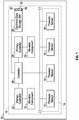
- FIG. 1 is a block diagram illustrating a non-limiting embodiment of a system 10 for controlling a pressure field around an aircraft 12.
- system 10 includes a plurality 14 of pressure sensors 16.
- plurality 14 includes many pressure sensors 16, only four of which have been illustrated in FIG. 1 for ease of illustration. It should be understood that in other embodiments, plurality 14 may include either a greater or a lesser number of pressure sensors 16 without departing from the teachings of the present disclosure.
- the embodiment of system 10 illustrated in FIG. 1 further includes a movable component 18 and a movable component 20. In other embodiments of system 10, either a greater or lesser number of movable components may be included.
- System 10 further includes a primary controller 22 and a primary controller 24 associated with movable component 18 and movable component 20, respectively.
- System 10 further includes an electronic data storage unit 26 and a controller 28.
- system 10 may include additional components or fewer components without departing from the teachings of the present disclosure.
- Pressure sensors 16 may comprise any type of pressure sensor, that is configured to measure pressure.
- pressure sensors 16 may be configured to measure static pressure, dynamic pressure, stagnation pressure, free stream pressure, ambient pressure, or combinations thereof.
- pressure sensors 16 comprise conventional pressure taps that are directly exposed to the free stream of flowing air adjacent aircraft 12.
- pressure sensors 16 may comprise optical pressure sensors such as those used in optical air data systems and that are configured to measure pressure through optical means (e.g., through the use of laser light), without direct contact with the free stream of flowing air proximate the exterior surface of the aircraft.
- each pressure sensor 16 comprises a pressure tap.
- Each pressure sensor 16 is mounted so that a portion of each pressure sensor is disposed on or just below the surface of aircraft 12 and is able to directly contact and sample the free stream of air flowing proximate the pressure sensor.
- Each pressure sensor 16 of plurality 14 is mounted at a known location with respect to the surface of aircraft 12 and is configured to take pressure readings in the vicinity of that known location. In some examples, each pressure sensor 16 may be configured to measure the pressure at a predetermined distance spaced apart from the surface of aircraft 12 (e.g., one foot, one meter, etc.).
- each pressure sensor 16 is communicatively coupled with controller 28.
- a direct hardwired connection between each pressure sensor 16 and controller 28 is illustrated in FIG. 1 .
- communicative coupling may be accomplished in any suitable manner including, but not limited to, the use of a communication bus, the use of wireless communications, and combinations thereof.
- Pressure sensors 16 are each configured to provide respective pressure readings to controller 28 that are indicative of the pressure conditions in their vicinity. Such pressure readings are delivered to controller 28 via the communicative coupling between each pressure sensor 16 and controller 28.
- Movable components 18 and 20 may comprise any component on the aircraft that is both configured for movement and which will alter the pressure field around aircraft 12 when it moves.
- the control surfaces e.g., ailerons, rudder, flaps, slats, etc.
- various components of the propulsion system of aircraft 12 will also affect the pressure field around aircraft 12 when they move. For example, changes to the engine cycle may impact the rate at which air enters and/or exits the propulsion system and therefore will affect the pressure field around aircraft 12.
- Movable/extendable inlet compression surfaces and nozzle surfaces will also impact the rate and conditions under which air enters the propulsion system and the rate and conditions at which air exits the propulsion system when they are moved/extended. Accordingly, movement of such extendable compression surfaces and nozzle plugs may affect the pressure field around aircraft 12. It should be understood that while Applicants have provided examples of movable components and of their effects on the pressure field around an aircraft in flight, the examples included above are not exhaustive. Other components may also be movable and have an effect on the pressure field around the aircraft and may serve as movable components 18 and 20.
- Primary controller 22 and primary controller 24 may comprise any type of controller, processor, computer, or other arrangement of circuitry that is configured to issue commands to movable component 18 and movable component 20, respectively, that cause movable component 18 and movable component 20 to move and/or to alter the manner in which said component is moving. It should be understood that reference herein to the movement of a movable component not only refers to the movement of a component that is currently stationary, but may also refer to the cessation of movement of a movable component that is currently moving and the alteration of the movement of a component that currently is moving (e.g., changing the rate of movement or changing the length or extent of such movement).
- movable component 18 may comprise a gas turbine engine or a component thereof (e.g., a compressor) and primary controller 22 may comprise a Full Authority Digital Electronic Controller (FADEC) that is configured to control operation of the gas turbine engine.
- movable component 20 may comprise a flight control surface (e.g., an aileron, a rudder, a flap, a slat, etc.) and primary controller 24 may comprise a Flight Control Computer (FCC) that is configured to control movement of the flight control surface.
- FCC Flight Control Computer
- primary controllers 22 and 24 are able to evaluate whether to reject commands issued by controller 28 or whether to accept and transmit such commands to movable components 18 and 20, as discussed in greater detail below.
- controller 28 may be directly communicatively coupled to movable component 18 and movable component 20.
- Electronic data storage unit 26 may comprise any type of data storage component including, without limitation, non-volatile memory, disk drives, tape drives, and mass storage devices and may include any suitable software, algorithms and/or sub-routines that provide the data storage component with the capability to store, organize, and permit retrieval of data.
- electronic data storage unit 26 is configured to store a file 30 containing information indicative of and/or relating to the pressure fields that are anticipated to arise (hereafter, "anticipated pressure fields") around aircraft 12 during flight.
- information may include, but is not limited to the pressure gradients that will be encountered in the anticipated pressure fields.
- This information may be gathered apriori in any suitable manner including, but not limited to, the use of appropriate computational fluid dynamics software, the collection and accumulation of data during testing under actual conditions, combinations thereof, and any other suitable means.
- file 30 may contain a series of anticipated pressure fields, each one corresponding with a different Mach speed within a range of Mach speeds that aircraft 12 is anticipated to encounter.
- file 30 may also contain a series of anticipated pressure fields, each one corresponding with different atmospheric conditions that aircraft 12 is anticipated to encounter.
- File 30, may also contain a series of anticipated pressure fields, each one corresponding with different operating conditions that aircraft 12 is anticipated to encounter.
- File 30 may also contain a series of anticipated pressure fields reflective of the pressure fields that are expected to develop around aircraft 12 as each of the Mach speed, the atmospheric conditions, and the operating conditions of aircraft 12 are varied in combination. In this manner, file 30 may contain anticipated pressure fields that correspond with substantially all combinations of Mach speed, atmospheric conditions, and operating conditions that aircraft 12 is anticipated to encounter.
- Controller 28 is communicatively coupled with electronic data storage unit 26. Through this communicative coupling, controller 28 has access to file 30. Configured in this manner, controller 28 will have access to, and can select anticipated pressure fields that correspond with the atmospheric conditions, operating conditions, and Mach speed encountered by aircraft 12 and controller 28 may use those anticipated pressure fields as a basis for comparison with the pressure field detected by plurality 14 of pressure sensors 16, as discussed in greater detail below.
- Electronic data storage unit 26 may be further configured to store a file 32 containing information indicative of the effect that movable component 18 will have on the pressure field around aircraft 12 when it is moved.
- File 32 may also contain information indicative of the extent of that effect in correlation to the extent that movable component 18 is moved.
- File 32 may also contain information that correlates the effect of such movement on the pressure field, and the extent of the effect corresponding to the extent of the movement, with the various Mach speeds, operating conditions, and atmospheric conditions that aircraft 12 is anticipated to encounter.
- file 32 may contain information indicative of how the movement and the extent of the movement of movable component 18 will affect the pressure field at the different Mach speeds that fall within the range of Mach speeds that aircraft 12 is anticipated to encounter.
- file 32 may contain information indicative of how the movement, and the extent of the movement, of movable component 18 will affect the pressure field at different atmospheric conditions that fall within the range of atmospheric conditions that aircraft 12 is anticipated to encounter. Further, file 32 may contain information indicative of how the movement and the extent of the movement of movable component 18 will affect the pressure field at each of the different operating conditions that fall within the range of operating conditions that aircraft 12 is anticipated to encounter. File 32 may further contain information indicative of how the movement and the extent of the movement of movable component 18 will affect the pressure field in various circumstances where the Mach speed, the atmospheric conditions and the operating conditions all deviate in anticipated manners from the design conditions.
- electronic data storage unit 26 may be configured to store a plurality of files 32, each containing information indicative of the effect that each additional movable component will have on the pressure filed around aircraft 12 as it is moved in the various conditions and operating states that aircraft 12 is anticipated to encounter. Configured in this manner, controller 28 will have access to a plurality of files 32 containing information that will allow controller 28 to determine which movable component or movable components should be moved to counteract or offset the propulsion system's effect on the pressure field around aircraft 12 and to what extent controller 28 should move said movable component(s).
- electronic data storage unit 26 may store a file 34 containing information indicative of the thresholds and/or limitations for the pressure field around aircraft 12 that are applicable to the different jurisdictions through which aircraft 12 may be flying.
- electronic data storage unit 26 may contain a file 34 for each of the jurisdictions identified in a flight plan, for each jurisdiction that aircraft 12 has previously flown to or through, and/or for each jurisdiction throughout the world that has restrictions on the magnitude of a sonic boom generated by aircraft during supersonic flight. Configured in this manner, controller 28 will have access to file 34, and therefore, will have access to information that will allow controller 28 to determine when corrective measures should be taken to offset the effect of the aircraft's propulsion system on the pressure field around aircraft 12.
- Controller 28 may be any type of computer, controller, micro-controller, circuitry, chipset, computer system, or microprocessor that is configured to perform algorithms, to execute software applications, to execute sub-routines and/or to be loaded with and to execute any other type of computer program. Controller 28 may comprise a single processor or a plurality of processors acting in concert. In some embodiments, controller 28 may be dedicated for use exclusively with system 10 while in other embodiments controller 28 may be shared with other systems on board aircraft 12.
- controller 28 is communicatively coupled with plurality 14 of pressure sensors 16, with primary controllers 22 and 24, and with electronic data storage unit 26. Controller 28 is communicatively connected to movable components 18 and 20 through primary controllers 22 and 24. These communicative couplings/connections may be accomplished through the use of any suitable means of transmission including both wired and wireless connections.
- each component may be physically connected to controller 28 via a coaxial cable or via any other type of wire connection that is effective to convey signals.
- each component may be communicatively connected to controller 28 across a communication bus.
- each component may be wirelessly connected to controller 28 via a BLUETOOTH connection, a WIFI connection or the like.
- the plurality 14 of pressure sensors 16, the primary controllers 22 and 24, and the electronic data storage unit 26 are each configured to interface and engage with controller 28.
- pressure sensors 16 are each configured to provide information to controller 28 indicative of their respective pressure readings and controller 28 is configured to receive such pressure readings.
- Primary controllers 22 and 24 are each configured to send and receive communications and/or instructions from controller 28 and controller 28 is configured to send and receive communications from primary controllers 22 and 24.
- Electronic data storage unit 26 is configured to receive communications, interrogations, and instructions from, and to provide information to, controller 28 and controller 28 is configured to send communications, interrogations, and instructions to, and to receive information from, electronic data storage unit 26.
- controller 28 is directly communicatively coupled with movable components 18 and 20
- movable components 18 and 20 are configured to receive and respond to communications, instructions, and commands issued by controller 28 and controller 28 is configured to communicate with, and to issue instructions to movable components 18 and 20 and to receive communications from movable components 18 and 20.
- Controller 28 is configured to interact with, coordinate and/or orchestrate the activities of each of the other components of system 10 for the purpose of controlling the pressure field that forms around aircraft 12 in flight.
- controller 28 is configured to receive pressure readings from each pressure sensor 16.
- controller 28 will be programed with, or will otherwise have access to information indicative of where each pressure sensor 16 is located with respect to an exterior surface of aircraft 12. Using the location information and the pressure readings provided by each pressure sensor 16, controller 28 is configured to calculate the pressure field around aircraft 12.
- controller 28 will have access to information indicative of the prevailing atmospheric conditions, the current Mach speed of aircraft 12, and the current operating conditions of aircraft 12. Controller 28 may obtain this information by communicating with other systems onboard aircraft 12 including, but not limited to, wireless transmitters, instrument panel gages, flight control computers, and the like.
- controller 28 is configured to communicate with electronic data storage unit 26 to obtain an anticipated pressure field that corresponds with the Mach speed of aircraft 12, the current operating conditions of aircraft 12, and the prevailing atmospheric conditions encountered by, or in the vicinity of, aircraft 12. Controller 28 is further configured to compare the anticipated pressure field obtained from electronic data storage unit 26 with the pressure field that it has calculated from the pressure readings provided by plurality 14 of pressure sensors 16. As part of the comparison, controller 28 may be programmed to identify deviations between the pressure gradients predicted in the anticipated pressure field with the pressure gradients that controller 28 detects during its calculation of the pressure field.
- controller 28 may be configured to use any suitable metric, either in addition to, or instead of, the anticipated pressure gradients and the detected pressure gradients when comparing the anticipated pressure field with the pressure field calculated by controller 28. In instances where a deviation is detected that does not coincide with the movement of a movable component, the deviation may be caused by the interaction between the propulsion system of aircraft 12 and the free stream of air flowing over aircraft 12.
- controller 28 may be configured to automatically take corrective measures when it detects the occurrence of any deviation between the anticipated pressure field and the pressure field that controller 28 calculates. In other embodiments, controller 28 may be configured to assess the deviation and only take corrective measures when the deviation exceeds a predetermined magnitude or threshold. In some examples, that predetermined magnitude may be programmed directly into controller 28. In other examples, controller 28 may be configured to obtain information from electronic data storage unit 26 that is indicative of acceptable deviations between the pressure field and the anticipated pressure field. In some embodiments, controller 28 may access file 32 to obtain this information. In some examples, such information may correspond with the jurisdiction that aircraft 12 is flying over.
- controller 28 is configured to obtain information relating to movable components 18 and 20. This information relates to the effect that movement of each movable component will have on the pressure field. In some embodiments, controller 28 will access file 32 to obtain this information. In other embodiments, such information may be programmed into controller 28 or be available from some other source accessible to controller 28. Using this information, controller 28 can determine which component to move and to what extent it should be moved in order to reduce the deviation between the anticipated pressure field and the pressure field that controller 28 has calculated.
- controller 28 may obtain information indicative of the effects on the pressure field of changing the engine cycle of the gas turbine engine of the propulsion system while flying at the current Mach speed, operating conditions, and prevailing atmospheric conditions. Controller 28 may also obtain information about the effects on the pressure field of moving the propulsion system's compression surface fore or aft while flying at the current Mach speed, operating conditions, and prevailing atmospheric conditions. Controller 28 may also obtain information about the effects on the pressure field of deflecting the ailerons of aircraft 12 up or down while flying at the current Mach speed, operating conditions, and prevailing atmospheric conditions. Controller 28 may obtain similar information relating to all movable components of system 10.
- controller 28 can determine which movable component to move in order to most advantageously reduce or entirely offset the deviation that controller 28 detected between the pressure field and the anticipated pressure field. Controller 28 may use other information as well when making this determination. For example, and without limitation, controller 28 may also take into consideration the effect on drag, the effect on the speed, the effect on fuel consumption, and any other suitable factor that may be impacted by movement of the movable component. For example, moving a control surface may have an undesirable effect on the angle of attack of aircraft 12 while changing the engine cycle may have an undesirable effect on the Mach speed of aircraft 12. Controller 28 may be programmed to prioritize the desirability or undesirability of effects such as these and may determine which movable component to move based on which movement will have the least undesirable effect.
- controller 28 is configured to transmit an instruction to the primary controller associated with that component.
- controller 28 is configured to send an instruction to primary controller 22 to move movable component 18 in the manner, and to the extent, determined by controller 28.
- primary controller 22 will comply with the instruction provided by controller 28 and will command movable component 18 to move in the manner determined by controller 28. In other embodiments, primary controller 22 will be configured to evaluate the command provided by controller 28 for compatibility with restrictions and limitations that govern the control that primary controller 22 exercises over movable component 18. If the command is found to be compatible with the restrictions and limitations programmed into primary controller 22, then primary controller 22 will send the command to movable component 18. However, in instances where the movement commanded by controller 28 is not compatible with the restrictions and limitations programmed into primary controller 22, primary controller 22 will not comply with the command. In instances where the command is only partially compatible with the restrictions and limitations programmed into primary controller 22, primary controller 22 will modify the command to provide partial compliance.
- primary controller 22 may be configured to send a message to controller 28 communicating its compliance with the command. In instances where primary controller 22 determines that compliance with the command is not appropriate, primary controller 22 may be configured to ignore the command and communicate its rejection of the command to controller 28. Similarly, in instances where primary controller 22 determines that only partial compliance with the command is appropriate, primary controller 22 may communicate its partial compliance to controller 28.
- controller 28 After controller 28 has provided the command to primary controller 22, controller 28 will continue to monitor the pressure field around aircraft 12 and compare it with the anticipated pressure field. If the deviation between the pressure field and the anticipated pressure field dissipates, then no further action by controller 28 may be needed. In instances where the deviation does not diminish or does not diminish sufficiently, or in instance where controller 28 receives a communication from primary controller 22 indicative of non-compliance or of only partial compliance, controller 28 may be configured to engage in further analysis to determine if alternate or further corrective measures are appropriate. In some instances, when the deviation does not sufficiently diminish, controller 28 may modify the original command to obtain further movement of movable component 18. In other instances, controller 28 may determine that movement of movable component 20 may be necessary.
- controller 28 may provide a command to primary controller 24 seeking movement of movable component 20.
- Primary controller 24 may be configured to either comply with the command or to engage in an analysis to determine whether the command is compatible with restrictions and limitations programmed into primary controller 24. After engaging in the analysis, primary controller 24 may fully comply with the command issued by controller 28 or it may only partially comply with the command or it may reject the command altogether.
- Primary controller 24 may be further configured to send a message to controller 28 indicative of its full compliance, partial compliance, or non-compliance, as appropriate.
- controller 28 After issuing the command, controller 28 will further monitor the pressure field to determine whether the deviation dissipates or sufficiently diminishes. If so, then controller 28 will take no further action other than to continue its monitoring of the pressure field. If the deviation does not dissipate, the analysis described above will repeat and controller 28 will determine how and whether to take action to reduce the deviation.
- the above described sampling, analysis, determination, issuance of commands, compliance with commands, and further monitoring of the pressure field around aircraft 12 may be performed automatically by system 10 without aircrew intervention, involvement, and/or awareness.
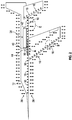
- FIGS. 2-6 depict aircraft 12 equipped with system 10 (see FIG. 1 ) during flight operations and further depict the stages of monitoring a pressure field 36 around aircraft 12, determining the existence of a deviation between pressure field 36 and the anticipated pressure field, and the corrective measures implemented by system 10.
- pressure field 36 has been illustrated through the use of multiple double headed arrows situated around aircraft 12.
- aircraft 12 is equipped with a propulsion system 38 comprising a gas turbine engine (not shown), an inlet 40 and a nozzle 42.
- Inlet 40 includes an extendable compression surface 44 configured for movement between a retracted position and an extended position. Extendable compression surface 44 is illustrated in FIG. 2 in its retracted position.
- Aircraft 12 further includes a plurality of pressure sensors 16 to detect and measure pressure field 36.
- aircraft 12 is configured with a large number of pressure sensors 16 arranged in a substantially equidistant pattern along substantially an entire length of the exterior of aircraft 12.
- pressure sensors 16 may be arranged in any other suitable manner.
- pressure sensors 16 may be concentrated in areas where interaction between propulsion system 38 and pressure field 36 is known to occur.
- pressure sensors 16 may be disposed only in areas where interaction between the propulsion system and the pressure field are known to occur.
- pressure sensors 16 have been circled and identified with reference letters. These pressure sensors 16 have been arranged in locations where adverse interaction between propulsion system 38 and pressure field 36 are anticipated.
- the pressure sensors 16 identified with the reference letter A are disposed in a region proximate inlet 40.
- the pressure sensors 16 identified with the references letter B are disposed in a region where a shock formed by the cowl lip of the propulsion system's nacelle is expected to intersect with the surface of aircraft 12.
- the pressure sensors 16 identified with the reference letter C are disposed in a region proximate nozzle 42. Arranged in this manner, any substantial change in pressure from one pressure sensor 16 to another pressure sensor 16 proximate propulsion system 38 will be detected.
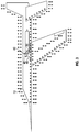
- FIG. 3 depicts a condition where a steep pressure gradient has formed proximate inlet 40.
- the steep pressure gradient is depicted through the use of elongated double headed arrows 46, 48, and 50, which are representative of elevated static pressure detected by pressure sensors 16 in the vicinity of inlet 40.
- Controller 28 will receive information indicative of this steep pressure gradient from pressure sensors 16 in the region identified with the reference letter A illustrated in FIG. 2 .
- controller 28 will determine that this steep pressure gradient is inconsistent with the pressure gradient of an anticipated pressure field associated with the current Mach speed, prevailing atmospheric conditions, and current operating conditions of aircraft 12. Controller 28 may make this determination by accessing file 30 stored in electronic data storage unit 26.
- controller 28 may evaluate whether the inconsistency between the detected pressure gradient and the anticipated pressure gradient exceeds a predetermined threshold in order to determine whether corrective measures are needed. Controller 28 may make this determination by accessing file 34 stored in electronic data storage unit 26. In the illustrated embodiment, controller 28 determines that corrective measures are needed.
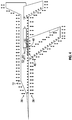
- controller 28 has sent a command to the primary controller associated with extendable compression surface 44 instructing the primary controller to extend extendable compression surface 44 by an amount determined by controller 28 to be necessary to offset the steep pressure gradient.
- Controller 28 may have determined which movable component to move and the amount of movement needed to diminish the deviation between the pressure field and the anticipated pressure field by accessing file 32 in electronic data storage unit 26.
- the primary controller associated with extendable compression surface 44 has determined that the command given by controller 28 is compatible with the limitations and restrictions that govern the primary controller and has forwarded the command to move to extendable compression surface 44.
- extendable compression surface 44 has moved in the direction indicated by arrow 52 to an extended position.
- FIGS. 5 and 6 An alternate scenario is illustrated in FIGS. 5 and 6 .
- extendable compression surface 44 has been moved to the extended position illustrated in FIG. 4 , but the steep pressure gradient illustrated by arrows 46, 48, and 50 has not diminished to an acceptable level.
- controller 28 detects the continued existence of a steep pressure gradient and determines that further action is needed.
- controller 28 determines that an appropriate action to further reduce the steep pressure gradient would be to move aileron 54. Controller 28 may have made this determination by accessing file 32 in electronic data storage unit 26. Controller 28 sends a command to the primary controller associated with aileron 54 requesting that aileron 54 be deflected in a downward direction to a specified angle.
- the primary controller associated with aileron 54 has determined that the command given by controller 28 is compatible with the limitations and restrictions that govern the primary controller and has forwarded the deflection command to aileron 54.
- aileron 54 has deflected downward in the manner illustrated in FIG. 6 .
- This movement of aileron 54, in combination with the movement of extendable compression surface 44 causes the steep pressure gradient detected in FIG. 5 to diminish as indicated by the diminution of arrows 46, 48, and 50.
- the deviation between pressure field 36 and the anticipated pressure field has diminished and pressure field 36 has returned to a pressure field that will not give rise to a sonic boom that will exceed applicable restrictions.
- FIG. 7 illustrates a non-limiting embodiment of a method 60 for controlling a pressure field around an aircraft.
- a pressure field around an aircraft is measured using a plurality of pressure sensors.
- the plurality of pressure sensors may be arranged along an exterior surface of the aircraft where they can directly sample the free stream of air flowing over the aircraft's surface.
- the pressure sensors may be located inside of the aircraft and may use optical means to take pressure measurements.
- the pressure sensors may be arranged in any suitable manner including, but not limited to, a substantially even distribution along the airframe or a concentrated arrangement in regions of the aircraft known or expected to experience steep pressure gradients.
- a controller on board the aircraft receives information from each of the pressure sensors indicative of the pressure readings taken by the pressure sensors.
- the controller determines when the pressure field deviates from a desired pressure field based, at least in part, on the information received from the plurality of pressure sensors.
- the controller may also utilize information pertaining to the aircraft's Mach speed, the prevailing atmospheric conditions, and the operating conditions of the aircraft.
- the controller may also use information stored in an electronic data storage unit indicative of an anticipated pressure field.
- the controller may also determine whether corrective measures are needed to reduce the deviation.
- the controller transmits an instruction to a movable component onboard the aircraft to move in a specified manner that is anticipated to cause a reduction in the deviation between the pressure field and the anticipated pressure field.
- the controller may transmit the command to an intermediate primary controller that is configured to control movement of the movable component.
- further monitoring by the controller may occur followed by the transmission of further commands to move the movable component further or to move other movable components on board the aircraft. This step may be repeated until the deviation diminishes completely or diminishes to a level below a predetermined threshold.
Landscapes
- Engineering & Computer Science (AREA)
- Aviation & Aerospace Engineering (AREA)
- Chemical & Material Sciences (AREA)
- Combustion & Propulsion (AREA)
- Automation & Control Theory (AREA)
- Mechanical Engineering (AREA)
- General Engineering & Computer Science (AREA)
- General Physics & Mathematics (AREA)
- Physics & Mathematics (AREA)
- Feedback Control In General (AREA)
- Traffic Control Systems (AREA)
- Measuring Fluid Pressure (AREA)
- Control Of Position, Course, Altitude, Or Attitude Of Moving Bodies (AREA)
Description
- The present invention generally relates to aircraft and more particularly relates to systems and methods for controlling a pressure field around an aircraft in flight.
- A quiet supersonic aircraft is a supersonic aircraft that will be able to comply with applicable governmental restrictions on the magnitude of sonic booms for flight over land or over other restricted areas, when such restrictions are set. Quiet supersonic aircraft will be designed to comply with such governmental restrictions when flying at a predetermined supersonic speed (e.g., Mach 1.7) and at predetermined atmospheric conditions (e.g., standard atmospheric conditions) and at predetermined operating conditions (e.g., throttle settings, angle of attack). When flying at the predetermined speed and the predetermined operating conditions through the predetermined atmospheric conditions, a quiet supersonic aircraft will have a pressure field around the aircraft that is substantially free from steep pressure gradients. As used herein, the phrase "steep pressure gradient" refers to a relatively large change in pressure over a relatively short distance.
- A pressure field free of steep pressure gradients, when propagated to the ground, can give rise to a sonic boom having a magnitude that falls below governmentally imposed limits. Any deviation from the predetermined supersonic speed or from the predetermined atmospheric conditions or from the predetermined operating conditions may give rise to a steep pressure gradient in the pressure field. If a steep pressure gradient were to form in the pressure field around the aircraft during supersonic flight, this could have an undesirable effect on the magnitude of the sonic boom that propagates to the ground.
- The propulsion system of a supersonic aircraft interacts aerodynamically with the airframe and with the pressure field around the supersonic aircraft. For example, the flow of air ingested by the propulsion system's inlet, the cycle at which the propulsion system's engine is operated, or the exhaust plume expelled by the propulsion system's nozzle will interact with the airflow around the supersonic aircraft's airframe. A quiet supersonic aircraft is designed such that when the propulsion system is operating at its design condition, the effect of the propulsion system on the pressure field will not give rise to a relatively steep gradient in the pressure field. As used herein, a reference to the design condition of a propulsion system refers to the predetermined engine cycle, the predetermined Mach speed, the predetermined atmospheric conditions, and the predetermined throttle settings that the engine will be operating at when the aircraft is operating at its design condition.
- However, when operation of the propulsion system deviates from the design condition (e.g., throttle settings that deviate from design throttle settings, operation at speeds other than design Mach speed, operation of the engine at an engine cycle that differs from a design engine cycle, operation of the propulsion system in other than the predetermined atmospheric conditions, etc.), the propulsion system can cause a relatively steep gradient to form in the pressure field around the aircraft. This is undesirable.
- Accordingly, it is desirable to provide a system that can control the pressure field around an aircraft in flight. In addition, it is desirable to provide a method for controlling the pressure field around an aircraft in flight. Furthermore, other desirable features and characteristics will become apparent from the subsequent summary and detailed description and the appended claims, taken in conjunction with the accompanying drawings and the foregoing technical field and background.
-
US 2010/0258678 A1 describes a stall protection system for use within an aircraft with a controller that is configured to compare a pressure differential value with one indicative of an impending stall condition. - The invention is defined in the appended independent claims, with dependent claims defining particular embodiments.
- Various embodiments of a system and a method for controlling a pressure field around an aircraft in flight are disclosed herein.
- According to the invention the system includes a plurality of pressure sensors arranged on the aircraft to measure the pressure field. The system further includes a controller that is communicatively coupled with the plurality of pressure sensors. The controller is configured to receive information that is indicative of the pressure field from the plurality of pressure sensors, to determine when the pressure field deviates from a desired pressure field based on the information, and to transmit an instruction to a movable component onboard the aircraft that will cause the movable component to move in a manner that reduces the deviation.
- In another aspect, the method includes measuring the pressure field with a plurality of pressure sensors arranged on the aircraft. The method further includes receiving, at a controller, information from the plurality of pressure sensors that is indicative of the pressure field. The method further includes, but is not limited to determining, with the processor, when the pressure field deviates from a desired pressure field based, at least in part, on the information from the plurality of pressure sensors; and transmitting, with the processor, an instruction to a movable component onboard the aircraft that will cause the movable component to move in a manner that reduces the deviation.
- In both the system and method aspects, an intermediate primary controller is provided that receives instructions from the controller to move the movable component and is configured to evaluate the instruction provided by the controller for compatibility with restrictions and limitations that govern a control of the primary controller over the movable component, and to not comply with the instruction transmitted by the controller in instances where the instruction is not compatible with restrictions and limitations programmed into the primary controller.
- The present invention will hereinafter be described in conjunction with the following drawing figures, wherein like numerals denote like elements, and
-
FIG. 1 is a block diagram illustrating a non-limiting embodiment of a system for controlling the pressure field around an aircraft in flight made in accordance with the teachings of the present disclosure; -
FIG. 2 is a schematic view illustrating an aircraft in flight equipped with the system ofFIG. 1 and showing the pressure field around the aircraft; -
FIG. 3 is a schematic view illustrating the aircraft ofFIG. 2 as it experiences a disturbance in the pressure field; -
FIG. 4 is a schematic view illustrating the aircraft ofFIG. 3 after a component has been moved which quells the disturbance in the pressure field; -
FIG. 5 is a schematic view illustrating the aircraft ofFIG. 3 after a first component has been moved which partially quells the disturbance in the pressure field; -
FIG. 6 is a schematic view illustrating the aircraft ofFIG. 6 after a second component has been moved to cooperate with the first component and completely quell the disturbance in the pressure field; and -
FIG. 7 is a flow chart depicting a non-limiting embodiment of a method for controlling the pressure field around an aircraft in flight. - The following detailed description is merely exemplary in nature and is not intended to limit the invention or the application and uses of the invention. Furthermore, there is no intention to be bound by any theory presented in the preceding background or the following detailed description.
- A system and method for controlling the pressure field around an aircraft in flight are disclosed herein. Multiple pressure sensors are positioned at various locations on the aircraft and are situated to measure the pressure in the vicinity of corresponding portions of the aircraft's exterior. In some embodiments, the pressure sensors are configured to measure dynamic pressure. In other embodiments, the pressure sensors may be configured to measure static pressure, stagnation pressure, or combinations thereof. In some embodiments, the pressure sensors may be disposed and/or concentrated at positions proximate the aircraft's propulsion system to better measure the effect of the propulsion system on the pressure field around the aircraft.
- A controller is communicatively coupled with the plurality of pressure sensors and is configured to receive the pressure readings from each pressure sensor. The controller compiles the pressure readings and determines the nature, parameters, gradients, and other measurable aspects of the pressure field around the aircraft. When the controller detects the presence or formation of a steep pressure gradient in the pressure field, the controller is configured to send an instruction to a movable component on the aircraft. The movable component is disposed in a location that permits it to interact with the air flowing over the exterior of the aircraft and preferably, flowing in, around, or through the aircraft's propulsion system. For example, the component may be associated with the aircraft's propulsion system such as an extendable compression surface or articulating fan blades of the engine's compressor. In other examples, the component may be one or more movable flight control surfaces positioned around the exterior of the aircraft. Movement of the movable component will have an impact on the pressure field. The controller will select a movable component that will have an effect on the pressure field that will reduce or offset entirely the steep pressure gradient detected by the controller.
- A greater understanding of the system for controlling the pressure field around an aircraft described above and of the method for controlling the pressure field around an aircraft may be obtained through a review of the illustrations accompanying this application together with a review of the detailed description that follows.
-
FIG. 1 is a block diagram illustrating a non-limiting embodiment of asystem 10 for controlling a pressure field around anaircraft 12. In the illustrated embodiment,system 10 includes aplurality 14 ofpressure sensors 16. InFIG. 1 ,plurality 14 includesmany pressure sensors 16, only four of which have been illustrated inFIG. 1 for ease of illustration. It should be understood that in other embodiments,plurality 14 may include either a greater or a lesser number ofpressure sensors 16 without departing from the teachings of the present disclosure. The embodiment ofsystem 10 illustrated inFIG. 1 further includes amovable component 18 and amovable component 20. In other embodiments ofsystem 10, either a greater or lesser number of movable components may be included.System 10 further includes aprimary controller 22 and aprimary controller 24 associated withmovable component 18 andmovable component 20, respectively.System 10 further includes an electronicdata storage unit 26 and acontroller 28. In other embodiments,system 10 may include additional components or fewer components without departing from the teachings of the present disclosure. -
Pressure sensors 16 may comprise any type of pressure sensor, that is configured to measure pressure. In some examples,pressure sensors 16 may be configured to measure static pressure, dynamic pressure, stagnation pressure, free stream pressure, ambient pressure, or combinations thereof. In the illustrated embodiment,pressure sensors 16 comprise conventional pressure taps that are directly exposed to the free stream of flowing airadjacent aircraft 12. In other embodiments,pressure sensors 16 may comprise optical pressure sensors such as those used in optical air data systems and that are configured to measure pressure through optical means (e.g., through the use of laser light), without direct contact with the free stream of flowing air proximate the exterior surface of the aircraft. - In the embodiment illustrated in
FIGS. 2-6 , eachpressure sensor 16 comprises a pressure tap. Eachpressure sensor 16 is mounted so that a portion of each pressure sensor is disposed on or just below the surface ofaircraft 12 and is able to directly contact and sample the free stream of air flowing proximate the pressure sensor. Eachpressure sensor 16 ofplurality 14 is mounted at a known location with respect to the surface ofaircraft 12 and is configured to take pressure readings in the vicinity of that known location. In some examples, eachpressure sensor 16 may be configured to measure the pressure at a predetermined distance spaced apart from the surface of aircraft 12 (e.g., one foot, one meter, etc.). - As illustrated in
FIG. 1 , eachpressure sensor 16 is communicatively coupled withcontroller 28. A direct hardwired connection between eachpressure sensor 16 andcontroller 28 is illustrated inFIG. 1 . In other embodiments, such communicative coupling may be accomplished in any suitable manner including, but not limited to, the use of a communication bus, the use of wireless communications, and combinations thereof.Pressure sensors 16 are each configured to provide respective pressure readings tocontroller 28 that are indicative of the pressure conditions in their vicinity. Such pressure readings are delivered tocontroller 28 via the communicative coupling between eachpressure sensor 16 andcontroller 28. -
Movable components aircraft 12 when it moves. For example, the control surfaces (e.g., ailerons, rudder, flaps, slats, etc.) ofaircraft 12 will each affect the pressure field aroundaircraft 12 when they move whileaircraft 12 is in flight. Further, various components of the propulsion system ofaircraft 12 will also affect the pressure field aroundaircraft 12 when they move. For example, changes to the engine cycle may impact the rate at which air enters and/or exits the propulsion system and therefore will affect the pressure field aroundaircraft 12. Movable/extendable inlet compression surfaces and nozzle surfaces will also impact the rate and conditions under which air enters the propulsion system and the rate and conditions at which air exits the propulsion system when they are moved/extended. Accordingly, movement of such extendable compression surfaces and nozzle plugs may affect the pressure field aroundaircraft 12. It should be understood that while Applicants have provided examples of movable components and of their effects on the pressure field around an aircraft in flight, the examples included above are not exhaustive. Other components may also be movable and have an effect on the pressure field around the aircraft and may serve asmovable components -
Primary controller 22 andprimary controller 24 may comprise any type of controller, processor, computer, or other arrangement of circuitry that is configured to issue commands tomovable component 18 andmovable component 20, respectively, that causemovable component 18 andmovable component 20 to move and/or to alter the manner in which said component is moving. It should be understood that reference herein to the movement of a movable component not only refers to the movement of a component that is currently stationary, but may also refer to the cessation of movement of a movable component that is currently moving and the alteration of the movement of a component that currently is moving (e.g., changing the rate of movement or changing the length or extent of such movement). In an example,movable component 18 may comprise a gas turbine engine or a component thereof (e.g., a compressor) andprimary controller 22 may comprise a Full Authority Digital Electronic Controller (FADEC) that is configured to control operation of the gas turbine engine. In another example,movable component 20 may comprise a flight control surface (e.g., an aileron, a rudder, a flap, a slat, etc.) andprimary controller 24 may comprise a Flight Control Computer (FCC) that is configured to control movement of the flight control surface. By positioningprimary controllers controller 28, on the one hand, andmovable component primary controllers movable components primary controllers controller 28 or whether to accept and transmit such commands tomovable components controller 28 may be directly communicatively coupled tomovable component 18 andmovable component 20. - Electronic
data storage unit 26 may comprise any type of data storage component including, without limitation, non-volatile memory, disk drives, tape drives, and mass storage devices and may include any suitable software, algorithms and/or sub-routines that provide the data storage component with the capability to store, organize, and permit retrieval of data. - In the illustrated embodiment, electronic
data storage unit 26 is configured to store afile 30 containing information indicative of and/or relating to the pressure fields that are anticipated to arise (hereafter, "anticipated pressure fields") aroundaircraft 12 during flight. Such information may include, but is not limited to the pressure gradients that will be encountered in the anticipated pressure fields. This information may be gathered apriori in any suitable manner including, but not limited to, the use of appropriate computational fluid dynamics software, the collection and accumulation of data during testing under actual conditions, combinations thereof, and any other suitable means. - The information relating to the anticipated pressure fields stored in
file 30 may correlate with different Mach speeds, different atmospheric conditions, different engine operating conditions, different aircraft states, and/or with other variables as well. For example, file 30 may contain a series of anticipated pressure fields, each one corresponding with a different Mach speed within a range of Mach speeds thataircraft 12 is anticipated to encounter.File 30 may also contain a series of anticipated pressure fields, each one corresponding with different atmospheric conditions thataircraft 12 is anticipated to encounter.File 30, may also contain a series of anticipated pressure fields, each one corresponding with different operating conditions thataircraft 12 is anticipated to encounter.File 30 may also contain a series of anticipated pressure fields reflective of the pressure fields that are expected to develop aroundaircraft 12 as each of the Mach speed, the atmospheric conditions, and the operating conditions ofaircraft 12 are varied in combination. In this manner, file 30 may contain anticipated pressure fields that correspond with substantially all combinations of Mach speed, atmospheric conditions, and operating conditions thataircraft 12 is anticipated to encounter. -
Controller 28 is communicatively coupled with electronicdata storage unit 26. Through this communicative coupling,controller 28 has access to file 30. Configured in this manner,controller 28 will have access to, and can select anticipated pressure fields that correspond with the atmospheric conditions, operating conditions, and Mach speed encountered byaircraft 12 andcontroller 28 may use those anticipated pressure fields as a basis for comparison with the pressure field detected byplurality 14 ofpressure sensors 16, as discussed in greater detail below. - Electronic
data storage unit 26 may be further configured to store afile 32 containing information indicative of the effect thatmovable component 18 will have on the pressure field aroundaircraft 12 when it is moved.File 32 may also contain information indicative of the extent of that effect in correlation to the extent thatmovable component 18 is moved.File 32 may also contain information that correlates the effect of such movement on the pressure field, and the extent of the effect corresponding to the extent of the movement, with the various Mach speeds, operating conditions, and atmospheric conditions thataircraft 12 is anticipated to encounter. For example, file 32 may contain information indicative of how the movement and the extent of the movement ofmovable component 18 will affect the pressure field at the different Mach speeds that fall within the range of Mach speeds thataircraft 12 is anticipated to encounter. Similarly, file 32 may contain information indicative of how the movement, and the extent of the movement, ofmovable component 18 will affect the pressure field at different atmospheric conditions that fall within the range of atmospheric conditions thataircraft 12 is anticipated to encounter. Further, file 32 may contain information indicative of how the movement and the extent of the movement ofmovable component 18 will affect the pressure field at each of the different operating conditions that fall within the range of operating conditions thataircraft 12 is anticipated to encounter.File 32 may further contain information indicative of how the movement and the extent of the movement ofmovable component 18 will affect the pressure field in various circumstances where the Mach speed, the atmospheric conditions and the operating conditions all deviate in anticipated manners from the design conditions. - In embodiments having more than two or more movable components, electronic
data storage unit 26 may be configured to store a plurality offiles 32, each containing information indicative of the effect that each additional movable component will have on the pressure filed aroundaircraft 12 as it is moved in the various conditions and operating states thataircraft 12 is anticipated to encounter. Configured in this manner,controller 28 will have access to a plurality offiles 32 containing information that will allowcontroller 28 to determine which movable component or movable components should be moved to counteract or offset the propulsion system's effect on the pressure field aroundaircraft 12 and to whatextent controller 28 should move said movable component(s). - In some embodiments, electronic
data storage unit 26 may store a file 34 containing information indicative of the thresholds and/or limitations for the pressure field aroundaircraft 12 that are applicable to the different jurisdictions through whichaircraft 12 may be flying. For example, electronicdata storage unit 26 may contain a file 34 for each of the jurisdictions identified in a flight plan, for each jurisdiction thataircraft 12 has previously flown to or through, and/or for each jurisdiction throughout the world that has restrictions on the magnitude of a sonic boom generated by aircraft during supersonic flight. Configured in this manner,controller 28 will have access to file 34, and therefore, will have access to information that will allowcontroller 28 to determine when corrective measures should be taken to offset the effect of the aircraft's propulsion system on the pressure field aroundaircraft 12. -
Controller 28 may be any type of computer, controller, micro-controller, circuitry, chipset, computer system, or microprocessor that is configured to perform algorithms, to execute software applications, to execute sub-routines and/or to be loaded with and to execute any other type of computer program.Controller 28 may comprise a single processor or a plurality of processors acting in concert. In some embodiments,controller 28 may be dedicated for use exclusively withsystem 10 while inother embodiments controller 28 may be shared with other systems onboard aircraft 12. - In the illustrated embodiment,
controller 28 is communicatively coupled withplurality 14 ofpressure sensors 16, withprimary controllers data storage unit 26.Controller 28 is communicatively connected tomovable components primary controllers controller 28 via a coaxial cable or via any other type of wire connection that is effective to convey signals. In other embodiments, each component may be communicatively connected tocontroller 28 across a communication bus. In still other examples, each component may be wirelessly connected tocontroller 28 via a BLUETOOTH connection, a WIFI connection or the like. - Being communicatively coupled and/or connected with each of the components identified above provides a pathway for the transmission of commands, instructions, interrogations and other signals between
controller 28 and each of the other components. Theplurality 14 ofpressure sensors 16, theprimary controllers data storage unit 26 are each configured to interface and engage withcontroller 28. For example,pressure sensors 16 are each configured to provide information tocontroller 28 indicative of their respective pressure readings andcontroller 28 is configured to receive such pressure readings.Primary controllers controller 28 andcontroller 28 is configured to send and receive communications fromprimary controllers data storage unit 26 is configured to receive communications, interrogations, and instructions from, and to provide information to,controller 28 andcontroller 28 is configured to send communications, interrogations, and instructions to, and to receive information from, electronicdata storage unit 26. In embodiments wherecontroller 28 is directly communicatively coupled withmovable components movable components controller 28 andcontroller 28 is configured to communicate with, and to issue instructions tomovable components movable components -
Controller 28 is configured to interact with, coordinate and/or orchestrate the activities of each of the other components ofsystem 10 for the purpose of controlling the pressure field that forms aroundaircraft 12 in flight. In a non-limiting example,controller 28 is configured to receive pressure readings from eachpressure sensor 16. In an embodiment,controller 28 will be programed with, or will otherwise have access to information indicative of where eachpressure sensor 16 is located with respect to an exterior surface ofaircraft 12. Using the location information and the pressure readings provided by eachpressure sensor 16,controller 28 is configured to calculate the pressure field aroundaircraft 12. In an embodiment,controller 28 will have access to information indicative of the prevailing atmospheric conditions, the current Mach speed ofaircraft 12, and the current operating conditions ofaircraft 12.Controller 28 may obtain this information by communicating with other systems onboardaircraft 12 including, but not limited to, wireless transmitters, instrument panel gages, flight control computers, and the like. - Using the current Mach speed and the current operating conditions of
aircraft 12, and using the prevailing atmospheric conditions in the vicinity ofaircraft 12,controller 28 is configured to communicate with electronicdata storage unit 26 to obtain an anticipated pressure field that corresponds with the Mach speed ofaircraft 12, the current operating conditions ofaircraft 12, and the prevailing atmospheric conditions encountered by, or in the vicinity of,aircraft 12.Controller 28 is further configured to compare the anticipated pressure field obtained from electronicdata storage unit 26 with the pressure field that it has calculated from the pressure readings provided byplurality 14 ofpressure sensors 16. As part of the comparison,controller 28 may be programmed to identify deviations between the pressure gradients predicted in the anticipated pressure field with the pressure gradients thatcontroller 28 detects during its calculation of the pressure field. In other embodiments,controller 28 may be configured to use any suitable metric, either in addition to, or instead of, the anticipated pressure gradients and the detected pressure gradients when comparing the anticipated pressure field with the pressure field calculated bycontroller 28. In instances where a deviation is detected that does not coincide with the movement of a movable component, the deviation may be caused by the interaction between the propulsion system ofaircraft 12 and the free stream of air flowing overaircraft 12. - In some embodiments,
controller 28 may be configured to automatically take corrective measures when it detects the occurrence of any deviation between the anticipated pressure field and the pressure field thatcontroller 28 calculates. In other embodiments,controller 28 may be configured to assess the deviation and only take corrective measures when the deviation exceeds a predetermined magnitude or threshold. In some examples, that predetermined magnitude may be programmed directly intocontroller 28. In other examples,controller 28 may be configured to obtain information from electronicdata storage unit 26 that is indicative of acceptable deviations between the pressure field and the anticipated pressure field. In some embodiments,controller 28 may access file 32 to obtain this information. In some examples, such information may correspond with the jurisdiction thataircraft 12 is flying over. - Once
controller 28 has determined that the deviation between the pressure field and the anticipated pressure field requires corrective measures,controller 28 is configured to obtain information relating tomovable components controller 28 will access file 32 to obtain this information. In other embodiments, such information may be programmed intocontroller 28 or be available from some other source accessible tocontroller 28. Using this information,controller 28 can determine which component to move and to what extent it should be moved in order to reduce the deviation between the anticipated pressure field and the pressure field thatcontroller 28 has calculated. - For example,
controller 28 may obtain information indicative of the effects on the pressure field of changing the engine cycle of the gas turbine engine of the propulsion system while flying at the current Mach speed, operating conditions, and prevailing atmospheric conditions.Controller 28 may also obtain information about the effects on the pressure field of moving the propulsion system's compression surface fore or aft while flying at the current Mach speed, operating conditions, and prevailing atmospheric conditions.Controller 28 may also obtain information about the effects on the pressure field of deflecting the ailerons ofaircraft 12 up or down while flying at the current Mach speed, operating conditions, and prevailing atmospheric conditions.Controller 28 may obtain similar information relating to all movable components ofsystem 10. - Using this information,
controller 28 can determine which movable component to move in order to most advantageously reduce or entirely offset the deviation thatcontroller 28 detected between the pressure field and the anticipated pressure field.Controller 28 may use other information as well when making this determination. For example, and without limitation,controller 28 may also take into consideration the effect on drag, the effect on the speed, the effect on fuel consumption, and any other suitable factor that may be impacted by movement of the movable component. For example, moving a control surface may have an undesirable effect on the angle of attack ofaircraft 12 while changing the engine cycle may have an undesirable effect on the Mach speed ofaircraft 12.Controller 28 may be programmed to prioritize the desirability or undesirability of effects such as these and may determine which movable component to move based on which movement will have the least undesirable effect. - Once
controller 28 has determined which movable component to move,controller 28 is configured to transmit an instruction to the primary controller associated with that component. In an example wherecontroller 28 has determined thatmovable component 18 should be moved and has further determined to what extent it should be moved,controller 28 is configured to send an instruction toprimary controller 22 to movemovable component 18 in the manner, and to the extent, determined bycontroller 28. - In some embodiments,
primary controller 22 will comply with the instruction provided bycontroller 28 and will commandmovable component 18 to move in the manner determined bycontroller 28. In other embodiments,primary controller 22 will be configured to evaluate the command provided bycontroller 28 for compatibility with restrictions and limitations that govern the control thatprimary controller 22 exercises overmovable component 18. If the command is found to be compatible with the restrictions and limitations programmed intoprimary controller 22, thenprimary controller 22 will send the command tomovable component 18. However, in instances where the movement commanded bycontroller 28 is not compatible with the restrictions and limitations programmed intoprimary controller 22,primary controller 22 will not comply with the command. In instances where the command is only partially compatible with the restrictions and limitations programmed intoprimary controller 22,primary controller 22 will modify the command to provide partial compliance. In instances whereprimary controller 22 fully complies with the command,primary controller 22 may be configured to send a message tocontroller 28 communicating its compliance with the command. In instances whereprimary controller 22 determines that compliance with the command is not appropriate,primary controller 22 may be configured to ignore the command and communicate its rejection of the command tocontroller 28. Similarly, in instances whereprimary controller 22 determines that only partial compliance with the command is appropriate,primary controller 22 may communicate its partial compliance tocontroller 28. - After
controller 28 has provided the command toprimary controller 22,controller 28 will continue to monitor the pressure field aroundaircraft 12 and compare it with the anticipated pressure field. If the deviation between the pressure field and the anticipated pressure field dissipates, then no further action bycontroller 28 may be needed. In instances where the deviation does not diminish or does not diminish sufficiently, or in instance wherecontroller 28 receives a communication fromprimary controller 22 indicative of non-compliance or of only partial compliance,controller 28 may be configured to engage in further analysis to determine if alternate or further corrective measures are appropriate. In some instances, when the deviation does not sufficiently diminish,controller 28 may modify the original command to obtain further movement ofmovable component 18. In other instances,controller 28 may determine that movement ofmovable component 20 may be necessary. In still other instances, such as whencontroller 28 receives a communication fromprimary controller 22 that compliance with the command will not be forthcoming or that only partial compliance will be provided, thencontroller 28 may provide a command toprimary controller 24 seeking movement ofmovable component 20.Primary controller 24 may be configured to either comply with the command or to engage in an analysis to determine whether the command is compatible with restrictions and limitations programmed intoprimary controller 24. After engaging in the analysis,primary controller 24 may fully comply with the command issued bycontroller 28 or it may only partially comply with the command or it may reject the command altogether.Primary controller 24 may be further configured to send a message tocontroller 28 indicative of its full compliance, partial compliance, or non-compliance, as appropriate. - After issuing the command,
controller 28 will further monitor the pressure field to determine whether the deviation dissipates or sufficiently diminishes. If so, thencontroller 28 will take no further action other than to continue its monitoring of the pressure field. If the deviation does not dissipate, the analysis described above will repeat andcontroller 28 will determine how and whether to take action to reduce the deviation. In some embodiments, the above described sampling, analysis, determination, issuance of commands, compliance with commands, and further monitoring of the pressure field aroundaircraft 12 may be performed automatically bysystem 10 without aircrew intervention, involvement, and/or awareness. -
FIGS. 2-6 depictaircraft 12 equipped with system 10 (seeFIG. 1 ) during flight operations and further depict the stages of monitoring apressure field 36 aroundaircraft 12, determining the existence of a deviation betweenpressure field 36 and the anticipated pressure field, and the corrective measures implemented bysystem 10. In the embodiments illustrated inFIGS. 2-6 ,pressure field 36 has been illustrated through the use of multiple double headed arrows situated aroundaircraft 12. - With respect to
FIG. 2 ,aircraft 12 is equipped with apropulsion system 38 comprising a gas turbine engine (not shown), aninlet 40 and anozzle 42.Inlet 40 includes anextendable compression surface 44 configured for movement between a retracted position and an extended position.Extendable compression surface 44 is illustrated inFIG. 2 in its retracted position. -
Aircraft 12 further includes a plurality ofpressure sensors 16 to detect and measurepressure field 36. In the illustrated embodiment,aircraft 12 is configured with a large number ofpressure sensors 16 arranged in a substantially equidistant pattern along substantially an entire length of the exterior ofaircraft 12. For ease of illustration, only small portion of the pressure sensors have been identified with thereference numeral 16. In other embodiments,pressure sensors 16 may be arranged in any other suitable manner. For example, in other embodiments,pressure sensors 16 may be concentrated in areas where interaction betweenpropulsion system 38 andpressure field 36 is known to occur. In still other embodiments,pressure sensors 16 may be disposed only in areas where interaction between the propulsion system and the pressure field are known to occur. - In the embodiment illustrated in
FIG. 2 ,several pressure sensors 16 have been circled and identified with reference letters. Thesepressure sensors 16 have been arranged in locations where adverse interaction betweenpropulsion system 38 andpressure field 36 are anticipated. For example, thepressure sensors 16 identified with the reference letter A are disposed in a regionproximate inlet 40. Thepressure sensors 16 identified with the references letter B are disposed in a region where a shock formed by the cowl lip of the propulsion system's nacelle is expected to intersect with the surface ofaircraft 12. Thepressure sensors 16 identified with the reference letter C are disposed in a regionproximate nozzle 42. Arranged in this manner, any substantial change in pressure from onepressure sensor 16 to anotherpressure sensor 16proximate propulsion system 38 will be detected. - With continuing reference to
FIGS. 1-2 ,FIG. 3 depicts a condition where a steep pressure gradient has formedproximate inlet 40. The steep pressure gradient is depicted through the use of elongated doubleheaded arrows pressure sensors 16 in the vicinity ofinlet 40.Controller 28 will receive information indicative of this steep pressure gradient frompressure sensors 16 in the region identified with the reference letter A illustrated inFIG. 2 . In the illustrated embodiment,controller 28 will determine that this steep pressure gradient is inconsistent with the pressure gradient of an anticipated pressure field associated with the current Mach speed, prevailing atmospheric conditions, and current operating conditions ofaircraft 12.Controller 28 may make this determination by accessingfile 30 stored in electronicdata storage unit 26. In some embodiments,controller 28 may evaluate whether the inconsistency between the detected pressure gradient and the anticipated pressure gradient exceeds a predetermined threshold in order to determine whether corrective measures are needed.Controller 28 may make this determination by accessing file 34 stored in electronicdata storage unit 26. In the illustrated embodiment,controller 28 determines that corrective measures are needed. - With respect to
FIG. 4 , and with continuing reference toFIGS. 1-3 ,controller 28 has sent a command to the primary controller associated withextendable compression surface 44 instructing the primary controller to extendextendable compression surface 44 by an amount determined bycontroller 28 to be necessary to offset the steep pressure gradient.Controller 28 may have determined which movable component to move and the amount of movement needed to diminish the deviation between the pressure field and the anticipated pressure field by accessingfile 32 in electronicdata storage unit 26. In the scenario illustrated inFIG. 4 , the primary controller associated withextendable compression surface 44 has determined that the command given bycontroller 28 is compatible with the limitations and restrictions that govern the primary controller and has forwarded the command to move toextendable compression surface 44. As a result,extendable compression surface 44 has moved in the direction indicated byarrow 52 to an extended position. Because of this movement ofextendable compression surface 44, the steep pressure gradient detected inFIG. 3 has diminished as indicated by the diminution ofarrows FIG. 4 . As a result, the deviation betweenpressure field 36 and the anticipated pressure field has diminished andpressure field 36 has returned to a pressure field that will not give rise to a sonic boom that will exceed applicable restrictions. - An alternate scenario is illustrated in
FIGS. 5 and6 . With continuing reference toFIGS. 1-4 , inFIG. 5 ,extendable compression surface 44 has been moved to the extended position illustrated inFIG. 4 , but the steep pressure gradient illustrated byarrows pressure field 36,controller 28 detects the continued existence of a steep pressure gradient and determines that further action is needed. - In
FIG. 6 ,controller 28 determines that an appropriate action to further reduce the steep pressure gradient would be to moveaileron 54.Controller 28 may have made this determination by accessingfile 32 in electronicdata storage unit 26.Controller 28 sends a command to the primary controller associated withaileron 54 requesting thataileron 54 be deflected in a downward direction to a specified angle. - In the scenario illustrated in
FIG. 6 , the primary controller associated withaileron 54 has determined that the command given bycontroller 28 is compatible with the limitations and restrictions that govern the primary controller and has forwarded the deflection command toaileron 54. As a result,aileron 54 has deflected downward in the manner illustrated inFIG. 6 . This movement ofaileron 54, in combination with the movement ofextendable compression surface 44 causes the steep pressure gradient detected inFIG. 5 to diminish as indicated by the diminution ofarrows pressure field 36 and the anticipated pressure field has diminished andpressure field 36 has returned to a pressure field that will not give rise to a sonic boom that will exceed applicable restrictions. -
FIG. 7 illustrates a non-limiting embodiment of amethod 60 for controlling a pressure field around an aircraft. - At
step 62, a pressure field around an aircraft is measured using a plurality of pressure sensors. In some embodiments, the plurality of pressure sensors may be arranged along an exterior surface of the aircraft where they can directly sample the free stream of air flowing over the aircraft's surface. In other embodiments, the pressure sensors may be located inside of the aircraft and may use optical means to take pressure measurements. The pressure sensors may be arranged in any suitable manner including, but not limited to, a substantially even distribution along the airframe or a concentrated arrangement in regions of the aircraft known or expected to experience steep pressure gradients. - At
step 64, a controller on board the aircraft receives information from each of the pressure sensors indicative of the pressure readings taken by the pressure sensors. - At
step 66, the controller determines when the pressure field deviates from a desired pressure field based, at least in part, on the information received from the plurality of pressure sensors. The controller may also utilize information pertaining to the aircraft's Mach speed, the prevailing atmospheric conditions, and the operating conditions of the aircraft. The controller may also use information stored in an electronic data storage unit indicative of an anticipated pressure field. In some embodiments ofmethod 60, the controller may also determine whether corrective measures are needed to reduce the deviation. - At
step 68, the controller transmits an instruction to a movable component onboard the aircraft to move in a specified manner that is anticipated to cause a reduction in the deviation between the pressure field and the anticipated pressure field. In some embodiments, the controller may transmit the command to an intermediate primary controller that is configured to control movement of the movable component. In some embodiments, further monitoring by the controller may occur followed by the transmission of further commands to move the movable component further or to move other movable components on board the aircraft. This step may be repeated until the deviation diminishes completely or diminishes to a level below a predetermined threshold. - While at least one exemplary embodiment has been presented in the foregoing detailed description of the disclosure, it should be appreciated that a vast number of variations exist. It should also be appreciated that the exemplary embodiment or exemplary embodiments are only examples, and are not intended to limit the scope, applicability, or configuration of the invention in any way. Rather, the foregoing detailed description will provide those skilled in the art with a convenient road map for implementing an exemplary embodiment of the invention. It being understood that various changes may be made in the function and arrangement of elements described in an exemplary embodiment without departing from the scope of the disclosure as set forth in the appended claims.
Claims (14)
- A system (10) for controlling a pressure field around an aircraft (12) in flight, the system comprising:a plurality (14) of pressure sensors (16) positionable at various locations on the aircraft so as to be situated to measure air pressure in a vicinity of corresponding portions of the aircraft's exterior; andan intermediate primary controller (22, 24) configured to control a movable component (18, 20) that is disposed in a position that alters the pressure field when the movable component moves while the aircraft is in flight;and a controller (28) communicatively coupled with the plurality of pressure sensors, the controller configured:to receive information from each pressure sensor indicative of a respective air pressure, to compute a pressure field along the external surface of the aircraft based on the information,to determine when the pressure field deviates from a desired pressure field based on the information,and to transmit an instruction to the movable component onboard the aircraft that will cause the movable component to move in a manner that reduces the deviation via the intermediate primary controller,wherein the intermediate primary controller is configured to evaluate the instruction provided by the controller for compatibility with restrictions and limitations that govern a control of the intermediate primary controller over the movable component and,wherein the intermediate primary controller is further configured to not comply with the instruction transmitted by the controller in instances where the instruction is not compatible with restrictions and limitations programmed into the intermediate primary controller.
- The system of claim 1, wherein the pressure field deviates from the desired pressure field when a pressure gradient of the pressure field exceeds a pressure gradient of the desired pressure field.
- The system of any one of the preceding claims,
wherein each pressure sensor of the plurality of pressure sensors is positioned to measure a respective air pressure proximate a respective portion of an external surface of the aircraft proximate a propulsion system of the aircraft;
wherein the system further comprises a first movable component mounted on the aircraft and disposed in a position that alters the pressure field when the first movable component moves while the aircraft is in flight; and
wherein the controller is further configured to detect a deviation between the pressure field and an anticipated pressure field caused by the propulsion system of the aircraft, and to send a first instruction to the first movable component to move in a manner that diminishes the deviation when the deviation is detected. - The system of claim 3, wherein the plurality of pressure sensors are arranged on the external surface of the aircraft.
- The system of claim 3 or 4, wherein the first movable component comprises a flight control surface.
- The system of any one of claims 3 to 5, wherein the first movable component comprises a propulsion system component.
- The system of any one of claims 3 to 6, wherein the controller sends the first instruction to the primary controller.
- The system of any one of claims 3 to 7, wherein detecting the deviation comprises comparing a pressure gradient of the pressure field with a corresponding pressure gradient of the anticipated pressure field.
- The system of any one of claims 3 to 8, wherein the controller is further configured to send the first instruction when the deviation exceeds a predetermined deviation.
- The system of any one of claims 3 to 9, further comprising a second movable component mounted on the aircraft and disposed in a second position that alters the pressure field when the second movable component moves while the aircraft is in flight,
wherein the controller is communicatively connected with the second movable component and is further configured to send a second instruction to the second movable component to move in a manner that diminishes the deviation when the deviation is detected. - The system of claim 10, wherein the controller is further configured to send the second instruction when movement of the first movable component fails to diminish the deviation by a predetermined amount; and/or
wherein the controller is further configured to send the second instruction when the first movable component does not move in response to the first instruction. - The system of any one of claims 3 to 11, wherein at least one pressure sensor of the plurality of pressure sensors is positioned to measure the respective air pressure proximate a propulsion system inlet and/or proximate a propulsion system nozzle and/or proximate a portion of the external surface where a shock generated by a structure of the aircraft intercepts the external surface.
- The system of any one of claims 3 to 12, further comprising an electronic data storage unit communicatively coupled with the controller and configured to store information indicative of a plurality of anticipated pressure fields,
wherein the controller is configured to retrieve the information from the electronic data storage unit and to use the information to detect the deviation between the pressure field and the anticipated pressure field. - A method for controlling a pressure field around an aircraft (12) in flight, the method comprising:measuring the pressure field with a plurality (14) of air pressure sensors (16) positioned at various locations on the aircraft and situated to measure pressure in a vicinity of corresponding portions of the aircraft's exterior;receiving, at a controller (28), information from the plurality of pressure sensors indicative of the pressure field;computing, with the controller, a pressure field along the external surface of the aircraft based on the information from the plurality of pressure sensors,determining, with the controller, when the pressure field deviates from a desired pressure field based, at least in part, on the information from the plurality of pressure sensors; and transmitting, with the controller, an instruction to a movable component (18, 20) that is disposed on board the aircraft in a position that alters the pressure field when the movable component moves while the aircraft is in flight, which instruction will cause the movable component to move in a manner that reduces the deviation via an intermediate primary controller (22, 24), controlling the movable component with the intermediate primary controller and, evaluating, by the intermediate primary controller, the instruction provided by the controller for compatibility with restrictions and limitations that govern a control of the primary controller over the movable component,wherein the intermediate primary controller is configured to not comply with the instruction transmitted by the controller in instances where the instruction is not compatible with restrictions and limitations programmed into the primary controller.
Applications Claiming Priority (2)
| Application Number | Priority Date | Filing Date | Title |
|---|---|---|---|
| US14/459,488 US9878778B2 (en) | 2014-08-14 | 2014-08-14 | System and method for controlling a pressure field around an aircraft in flight |
| PCT/US2015/017660 WO2016025029A1 (en) | 2014-08-14 | 2015-02-26 | System and method for controlling a pressure field around an aircraft in flight |
Publications (2)
| Publication Number | Publication Date |
|---|---|
| EP3180244A1 EP3180244A1 (en) | 2017-06-21 |
| EP3180244B1 true EP3180244B1 (en) | 2019-09-11 |
Family
ID=54148608
Family Applications (1)
| Application Number | Title | Priority Date | Filing Date |
|---|---|---|---|
| EP15766673.6A Active EP3180244B1 (en) | 2014-08-14 | 2015-02-26 | System and method for controlling a pressure field around an aircraft in flight |
Country Status (6)
| Country | Link |
|---|---|
| US (1) | US9878778B2 (en) |
| EP (1) | EP3180244B1 (en) |
| JP (1) | JP6590419B2 (en) |
| CN (1) | CN107074345B (en) |
| ES (1) | ES2761648T3 (en) |
| WO (1) | WO2016025029A1 (en) |
Families Citing this family (9)
| Publication number | Priority date | Publication date | Assignee | Title |
|---|---|---|---|---|
| EP3462178B1 (en) | 2017-09-22 | 2021-05-26 | Rosemount Aerospace Inc. | Low profile air data architecture |
| EP3460436A1 (en) | 2017-09-22 | 2019-03-27 | Rosemount Aerospace Inc. | Low profile sensor |
| CN108382565B (en) * | 2018-03-22 | 2024-03-22 | 北航(四川)西部国际创新港科技有限公司 | Flap automatically regulated aircraft |
| US20200385133A1 (en) * | 2019-06-06 | 2020-12-10 | Gulfstream Aerospace Corporation | Engine and thrust control of aircraft in no dwell zone |
| EP3808655B1 (en) * | 2019-10-16 | 2022-08-31 | Aircraft Cabin Modification GmbH | Useful payload monitoring system, aircraft and method |
| JP7458052B2 (en) * | 2019-11-14 | 2024-03-29 | 国立研究開発法人宇宙航空研究開発機構 | Turbulence sensing system, aircraft and turbulence sensing method |
| CN111156995A (en) * | 2020-01-22 | 2020-05-15 | 南京航空航天大学 | Intelligent aircraft based on flight state perception and flight method |
| US20210233413A1 (en) * | 2020-01-23 | 2021-07-29 | Aerion Intellectual Property Management Corporation | Real-time automated method and system enabling continuous supersonic flight while preventing ground level sonic boom |
| CN117760681B (en) * | 2024-02-22 | 2024-05-31 | 中国空气动力研究与发展中心高速空气动力研究所 | Combined type acoustic explosion test device and method suitable for large supersonic wind tunnel |
Family Cites Families (26)
| Publication number | Priority date | Publication date | Assignee | Title |
|---|---|---|---|---|
| FR1071234A (en) * | 1952-11-19 | 1954-08-27 | Sncase | Method and device for adapting the aerodynamic profiles to a sharp leading edge at any speed, subsonic or supersonic |
| US2997843A (en) * | 1958-04-23 | 1961-08-29 | Bendix Corp | Inlet control system for supersonic aircraft |
| IT699976A (en) * | 1959-02-17 | 1900-01-01 | ||
| US3221549A (en) * | 1962-11-09 | 1965-12-07 | Joseph W Wetmore | Aircraft instrument |
| US3181818A (en) * | 1964-05-15 | 1965-05-04 | United Aircraft Corp | Shock wave position controller |
| US4114842A (en) * | 1977-03-28 | 1978-09-19 | Sperry Rand Corporation | Acceleration limited preselect altitude capture and control |
| US4648569A (en) * | 1985-10-23 | 1987-03-10 | The United States Of America As Represented By The Administrator Of The National Aeronautics And Space Administration | Airplane automatic control force trimming device for asymmetric engine failures |
| JPS6385500U (en) * | 1986-11-21 | 1988-06-03 | ||
| JPH01254491A (en) * | 1988-04-04 | 1989-10-11 | Mitsubishi Heavy Ind Ltd | Front edge flap device |
| US5186415A (en) * | 1990-05-14 | 1993-02-16 | Qun Li | Aircraft having means for controlling the ground effect flying altitude by sensing air pressure on the surface of the wing |
| CN1064016C (en) * | 1992-07-16 | 2001-04-04 | 李群 | Weak ground effect flying vehicle |
| US5448881A (en) * | 1993-06-09 | 1995-09-12 | United Technologies Corporation | Gas turbine engine control based on inlet pressure distortion |
| DE4422152C2 (en) * | 1994-06-27 | 2000-02-03 | Daimler Chrysler Aerospace | Method and arrangement for optimizing the aerodynamic effect of a wing |
| US5669582A (en) * | 1995-05-12 | 1997-09-23 | The Boeing Company | Method and apparatus for reducing unwanted sideways motion in the aft cabin and roll-yaw upsets of an airplane due to atmospheric turbulence and wind gusts |
| US5875998A (en) * | 1996-02-05 | 1999-03-02 | Daimler-Benz Aerospace Airbus Gmbh | Method and apparatus for optimizing the aerodynamic effect of an airfoil |
| JP2000227048A (en) * | 1999-02-05 | 2000-08-15 | Ishikawajima Harima Heavy Ind Co Ltd | Jet noise reduction method and mechanism |
| US6905091B2 (en) * | 2003-07-14 | 2005-06-14 | Supersonic Aerospace International, Llc | System and method for controlling the acoustic signature of a device |
| US20070252035A1 (en) * | 2005-11-29 | 2007-11-01 | Hubbard James E Jr | Unmanned vehicle |
| EP2180183A1 (en) * | 2008-10-23 | 2010-04-28 | Siemens Aktiengesellschaft | Stall detection by use of pressure sensors |
| US20100258678A1 (en) * | 2009-04-09 | 2010-10-14 | Nicholas Jonathan Fermor | Aircraft stall protection system |
| WO2011005797A1 (en) * | 2009-07-07 | 2011-01-13 | Wms Gaming, Inc. | Controlling gaming effects for gaming network nodes |
| US8320217B1 (en) * | 2009-10-01 | 2012-11-27 | Raytheon Bbn Technologies Corp. | Systems and methods for disambiguating shooter locations with shockwave-only location |
| US20130345910A1 (en) * | 2011-02-11 | 2013-12-26 | The Board Of Trustees Of The University Of Illinois | Detector function and system for predicting airfoil stall from control surface measurements |
| US8788122B1 (en) * | 2012-08-24 | 2014-07-22 | The Boeing Company | Wing load alleviation methods and apparatus |
| WO2015065551A1 (en) * | 2013-07-25 | 2015-05-07 | Lam Aviation, Inc. | Aircraft wing structure and control system |
| US9334807B2 (en) * | 2014-05-13 | 2016-05-10 | The Boeing Company | Methods and apparatus to determine airflow conditions at an inlet of an engine |
-
2014
- 2014-08-14 US US14/459,488 patent/US9878778B2/en not_active Expired - Fee Related
-
2015
- 2015-02-26 CN CN201580049510.0A patent/CN107074345B/en not_active Expired - Fee Related
- 2015-02-26 WO PCT/US2015/017660 patent/WO2016025029A1/en not_active Ceased
- 2015-02-26 EP EP15766673.6A patent/EP3180244B1/en active Active
- 2015-02-26 ES ES15766673T patent/ES2761648T3/en active Active
- 2015-02-26 JP JP2017507432A patent/JP6590419B2/en not_active Expired - Fee Related
Non-Patent Citations (1)
| Title |
|---|
| None * |
Also Published As
| Publication number | Publication date |
|---|---|
| ES2761648T3 (en) | 2020-05-20 |
| US20160257397A1 (en) | 2016-09-08 |
| JP6590419B2 (en) | 2019-10-16 |
| JP2017523089A (en) | 2017-08-17 |
| EP3180244A1 (en) | 2017-06-21 |
| US9878778B2 (en) | 2018-01-30 |
| CN107074345B (en) | 2020-01-07 |
| CN107074345A (en) | 2017-08-18 |
| WO2016025029A1 (en) | 2016-02-18 |
Similar Documents
| Publication | Publication Date | Title |
|---|---|---|
| US9878778B2 (en) | System and method for controlling a pressure field around an aircraft in flight | |
| US8989953B2 (en) | Method for predicting a trailing edge flap fault | |
| EP2533122B1 (en) | Climb-optimized auto takeoff system | |
| US8653990B2 (en) | Stall management system | |
| JP6055534B2 (en) | System and method for identifying aircraft defects | |
| US20150066288A1 (en) | Methods for predicting a speed brake system fault | |
| RU2561168C2 (en) | Aeroplane control system, aeroplane and aeroplane control method | |
| US8665120B2 (en) | Primary flight display pitch- and power-based unreliable airspeed symbology | |
| US8000845B2 (en) | Method and device for dynamically alleviating loads generated on an airplane | |
| US9688418B2 (en) | Method for determining a state of a component in a high lift system of an aircraft, high lift system of an aircraft, and aircraft having such a high lift system | |
| US9302763B2 (en) | Method for diagnosing a trailing edge flap fault | |
| EP2500792B1 (en) | Variable maximum commandable roll rate for directional control of an aircraft during engine-out rolling maneuver | |
| CN104108466A (en) | Flight System For An Aircraft Having An Autoland System | |
| CN104108474A (en) | Method For Predicting A Bleed Air System Fault | |
| EP3578457A1 (en) | Method and apparatus for reducing aircraft wing bending moment | |
| US20140336871A1 (en) | Method for diagnosing a speed brake system fault | |
| Zanella | A methodology to improve the proactive mitigation of helicopter accidents related to loss of tail rotor effectiveness | |
| US10450966B2 (en) | Device and method for regulating a motor using a thrust measurement | |
| Ellison et al. | Design and flight testing of the X-35 air data system | |
| Zhimin et al. | Research Article Analysis of Security Window in Automatic Landing of the Carrier-borne Aircraft |
Legal Events
| Date | Code | Title | Description |
|---|---|---|---|
| STAA | Information on the status of an ep patent application or granted ep patent |
Free format text: STATUS: THE INTERNATIONAL PUBLICATION HAS BEEN MADE |
|
| PUAI | Public reference made under article 153(3) epc to a published international application that has entered the european phase |
Free format text: ORIGINAL CODE: 0009012 |
|
| STAA | Information on the status of an ep patent application or granted ep patent |
Free format text: STATUS: REQUEST FOR EXAMINATION WAS MADE |
|
| 17P | Request for examination filed |
Effective date: 20170221 |
|
| AK | Designated contracting states |
Kind code of ref document: A1 Designated state(s): AL AT BE BG CH CY CZ DE DK EE ES FI FR GB GR HR HU IE IS IT LI LT LU LV MC MK MT NL NO PL PT RO RS SE SI SK SM TR |
|
| AX | Request for extension of the european patent |
Extension state: BA ME |
|
| DAX | Request for extension of the european patent (deleted) | ||
| STAA | Information on the status of an ep patent application or granted ep patent |
Free format text: STATUS: EXAMINATION IS IN PROGRESS |
|
| 17Q | First examination report despatched |
Effective date: 20180801 |
|
| GRAP | Despatch of communication of intention to grant a patent |
Free format text: ORIGINAL CODE: EPIDOSNIGR1 |
|
| STAA | Information on the status of an ep patent application or granted ep patent |
Free format text: STATUS: GRANT OF PATENT IS INTENDED |
|
| INTG | Intention to grant announced |
Effective date: 20190423 |
|
| GRAS | Grant fee paid |
Free format text: ORIGINAL CODE: EPIDOSNIGR3 |
|
| GRAA | (expected) grant |
Free format text: ORIGINAL CODE: 0009210 |
|
| STAA | Information on the status of an ep patent application or granted ep patent |
Free format text: STATUS: THE PATENT HAS BEEN GRANTED |
|
| AK | Designated contracting states |
Kind code of ref document: B1 Designated state(s): AL AT BE BG CH CY CZ DE DK EE ES FI FR GB GR HR HU IE IS IT LI LT LU LV MC MK MT NL NO PL PT RO RS SE SI SK SM TR |
|
| REG | Reference to a national code |
Ref country code: GB Ref legal event code: FG4D |
|
| REG | Reference to a national code |
Ref country code: CH Ref legal event code: EP |
|
| REG | Reference to a national code |
Ref country code: AT Ref legal event code: REF Ref document number: 1178126 Country of ref document: AT Kind code of ref document: T Effective date: 20190915 |
|
| REG | Reference to a national code |
Ref country code: DE Ref legal event code: R096 Ref document number: 602015037846 Country of ref document: DE Ref country code: IE Ref legal event code: FG4D |
|
| REG | Reference to a national code |
Ref country code: SE Ref legal event code: TRGR |
|
| REG | Reference to a national code |
Ref country code: NL Ref legal event code: MP Effective date: 20190911 |
|
| REG | Reference to a national code |
Ref country code: LT Ref legal event code: MG4D |
|
| PG25 | Lapsed in a contracting state [announced via postgrant information from national office to epo] |
Ref country code: NO Free format text: LAPSE BECAUSE OF FAILURE TO SUBMIT A TRANSLATION OF THE DESCRIPTION OR TO PAY THE FEE WITHIN THE PRESCRIBED TIME-LIMIT Effective date: 20191211 Ref country code: BG Free format text: LAPSE BECAUSE OF FAILURE TO SUBMIT A TRANSLATION OF THE DESCRIPTION OR TO PAY THE FEE WITHIN THE PRESCRIBED TIME-LIMIT Effective date: 20191211 Ref country code: LT Free format text: LAPSE BECAUSE OF FAILURE TO SUBMIT A TRANSLATION OF THE DESCRIPTION OR TO PAY THE FEE WITHIN THE PRESCRIBED TIME-LIMIT Effective date: 20190911 Ref country code: HR Free format text: LAPSE BECAUSE OF FAILURE TO SUBMIT A TRANSLATION OF THE DESCRIPTION OR TO PAY THE FEE WITHIN THE PRESCRIBED TIME-LIMIT Effective date: 20190911 Ref country code: FI Free format text: LAPSE BECAUSE OF FAILURE TO SUBMIT A TRANSLATION OF THE DESCRIPTION OR TO PAY THE FEE WITHIN THE PRESCRIBED TIME-LIMIT Effective date: 20190911 |
|
| PG25 | Lapsed in a contracting state [announced via postgrant information from national office to epo] |
Ref country code: LV Free format text: LAPSE BECAUSE OF FAILURE TO SUBMIT A TRANSLATION OF THE DESCRIPTION OR TO PAY THE FEE WITHIN THE PRESCRIBED TIME-LIMIT Effective date: 20190911 Ref country code: AL Free format text: LAPSE BECAUSE OF FAILURE TO SUBMIT A TRANSLATION OF THE DESCRIPTION OR TO PAY THE FEE WITHIN THE PRESCRIBED TIME-LIMIT Effective date: 20190911 Ref country code: GR Free format text: LAPSE BECAUSE OF FAILURE TO SUBMIT A TRANSLATION OF THE DESCRIPTION OR TO PAY THE FEE WITHIN THE PRESCRIBED TIME-LIMIT Effective date: 20191212 Ref country code: RS Free format text: LAPSE BECAUSE OF FAILURE TO SUBMIT A TRANSLATION OF THE DESCRIPTION OR TO PAY THE FEE WITHIN THE PRESCRIBED TIME-LIMIT Effective date: 20190911 |
|
| REG | Reference to a national code |
Ref country code: AT Ref legal event code: MK05 Ref document number: 1178126 Country of ref document: AT Kind code of ref document: T Effective date: 20190911 |
|
| PG25 | Lapsed in a contracting state [announced via postgrant information from national office to epo] |
Ref country code: PT Free format text: LAPSE BECAUSE OF FAILURE TO SUBMIT A TRANSLATION OF THE DESCRIPTION OR TO PAY THE FEE WITHIN THE PRESCRIBED TIME-LIMIT Effective date: 20200113 Ref country code: RO Free format text: LAPSE BECAUSE OF FAILURE TO SUBMIT A TRANSLATION OF THE DESCRIPTION OR TO PAY THE FEE WITHIN THE PRESCRIBED TIME-LIMIT Effective date: 20190911 Ref country code: AT Free format text: LAPSE BECAUSE OF FAILURE TO SUBMIT A TRANSLATION OF THE DESCRIPTION OR TO PAY THE FEE WITHIN THE PRESCRIBED TIME-LIMIT Effective date: 20190911 Ref country code: PL Free format text: LAPSE BECAUSE OF FAILURE TO SUBMIT A TRANSLATION OF THE DESCRIPTION OR TO PAY THE FEE WITHIN THE PRESCRIBED TIME-LIMIT Effective date: 20190911 Ref country code: EE Free format text: LAPSE BECAUSE OF FAILURE TO SUBMIT A TRANSLATION OF THE DESCRIPTION OR TO PAY THE FEE WITHIN THE PRESCRIBED TIME-LIMIT Effective date: 20190911 Ref country code: NL Free format text: LAPSE BECAUSE OF FAILURE TO SUBMIT A TRANSLATION OF THE DESCRIPTION OR TO PAY THE FEE WITHIN THE PRESCRIBED TIME-LIMIT Effective date: 20190911 |
|
| PGFP | Annual fee paid to national office [announced via postgrant information from national office to epo] |
Ref country code: SE Payment date: 20200227 Year of fee payment: 6 Ref country code: GB Payment date: 20200227 Year of fee payment: 6 Ref country code: ES Payment date: 20200302 Year of fee payment: 6 Ref country code: DE Payment date: 20200227 Year of fee payment: 6 Ref country code: IT Payment date: 20200220 Year of fee payment: 6 |
|
| REG | Reference to a national code |
Ref country code: ES Ref legal event code: FG2A Ref document number: 2761648 Country of ref document: ES Kind code of ref document: T3 Effective date: 20200520 |
|
| PG25 | Lapsed in a contracting state [announced via postgrant information from national office to epo] |
Ref country code: SM Free format text: LAPSE BECAUSE OF FAILURE TO SUBMIT A TRANSLATION OF THE DESCRIPTION OR TO PAY THE FEE WITHIN THE PRESCRIBED TIME-LIMIT Effective date: 20190911 Ref country code: CZ Free format text: LAPSE BECAUSE OF FAILURE TO SUBMIT A TRANSLATION OF THE DESCRIPTION OR TO PAY THE FEE WITHIN THE PRESCRIBED TIME-LIMIT Effective date: 20190911 Ref country code: IS Free format text: LAPSE BECAUSE OF FAILURE TO SUBMIT A TRANSLATION OF THE DESCRIPTION OR TO PAY THE FEE WITHIN THE PRESCRIBED TIME-LIMIT Effective date: 20200224 Ref country code: SK Free format text: LAPSE BECAUSE OF FAILURE TO SUBMIT A TRANSLATION OF THE DESCRIPTION OR TO PAY THE FEE WITHIN THE PRESCRIBED TIME-LIMIT Effective date: 20190911 |
|
| REG | Reference to a national code |
Ref country code: DE Ref legal event code: R097 Ref document number: 602015037846 Country of ref document: DE |
|
| PGFP | Annual fee paid to national office [announced via postgrant information from national office to epo] |
Ref country code: FR Payment date: 20200225 Year of fee payment: 6 |
|
| PLBE | No opposition filed within time limit |
Free format text: ORIGINAL CODE: 0009261 |
|
| STAA | Information on the status of an ep patent application or granted ep patent |
Free format text: STATUS: NO OPPOSITION FILED WITHIN TIME LIMIT |
|
| PG2D | Information on lapse in contracting state deleted |
Ref country code: IS |
|
| PG25 | Lapsed in a contracting state [announced via postgrant information from national office to epo] |
Ref country code: IS Free format text: LAPSE BECAUSE OF FAILURE TO SUBMIT A TRANSLATION OF THE DESCRIPTION OR TO PAY THE FEE WITHIN THE PRESCRIBED TIME-LIMIT Effective date: 20200112 Ref country code: DK Free format text: LAPSE BECAUSE OF FAILURE TO SUBMIT A TRANSLATION OF THE DESCRIPTION OR TO PAY THE FEE WITHIN THE PRESCRIBED TIME-LIMIT Effective date: 20190911 |
|
| 26N | No opposition filed |
Effective date: 20200615 |
|
| PG25 | Lapsed in a contracting state [announced via postgrant information from national office to epo] |
Ref country code: SI Free format text: LAPSE BECAUSE OF FAILURE TO SUBMIT A TRANSLATION OF THE DESCRIPTION OR TO PAY THE FEE WITHIN THE PRESCRIBED TIME-LIMIT Effective date: 20190911 |
|
| REG | Reference to a national code |
Ref country code: CH Ref legal event code: PL |
|
| REG | Reference to a national code |
Ref country code: BE Ref legal event code: MM Effective date: 20200229 |
|
| PG25 | Lapsed in a contracting state [announced via postgrant information from national office to epo] |
Ref country code: MC Free format text: LAPSE BECAUSE OF FAILURE TO SUBMIT A TRANSLATION OF THE DESCRIPTION OR TO PAY THE FEE WITHIN THE PRESCRIBED TIME-LIMIT Effective date: 20190911 Ref country code: LU Free format text: LAPSE BECAUSE OF NON-PAYMENT OF DUE FEES Effective date: 20200226 |
|
| PG25 | Lapsed in a contracting state [announced via postgrant information from national office to epo] |
Ref country code: LI Free format text: LAPSE BECAUSE OF NON-PAYMENT OF DUE FEES Effective date: 20200229 Ref country code: CH Free format text: LAPSE BECAUSE OF NON-PAYMENT OF DUE FEES Effective date: 20200229 |
|
| PG25 | Lapsed in a contracting state [announced via postgrant information from national office to epo] |
Ref country code: IE Free format text: LAPSE BECAUSE OF NON-PAYMENT OF DUE FEES Effective date: 20200226 |
|
| PG25 | Lapsed in a contracting state [announced via postgrant information from national office to epo] |
Ref country code: BE Free format text: LAPSE BECAUSE OF NON-PAYMENT OF DUE FEES Effective date: 20200229 |
|
| REG | Reference to a national code |
Ref country code: DE Ref legal event code: R119 Ref document number: 602015037846 Country of ref document: DE |
|
| REG | Reference to a national code |
Ref country code: SE Ref legal event code: EUG |
|
| GBPC | Gb: european patent ceased through non-payment of renewal fee |
Effective date: 20210226 |
|
| PG25 | Lapsed in a contracting state [announced via postgrant information from national office to epo] |
Ref country code: SE Free format text: LAPSE BECAUSE OF NON-PAYMENT OF DUE FEES Effective date: 20210227 |
|
| PG25 | Lapsed in a contracting state [announced via postgrant information from national office to epo] |
Ref country code: FR Free format text: LAPSE BECAUSE OF NON-PAYMENT OF DUE FEES Effective date: 20210228 Ref country code: GB Free format text: LAPSE BECAUSE OF NON-PAYMENT OF DUE FEES Effective date: 20210226 Ref country code: DE Free format text: LAPSE BECAUSE OF NON-PAYMENT OF DUE FEES Effective date: 20210901 |
|
| PG25 | Lapsed in a contracting state [announced via postgrant information from national office to epo] |
Ref country code: IT Free format text: LAPSE BECAUSE OF NON-PAYMENT OF DUE FEES Effective date: 20210226 |
|
| REG | Reference to a national code |
Ref country code: ES Ref legal event code: FD2A Effective date: 20220513 |
|
| PG25 | Lapsed in a contracting state [announced via postgrant information from national office to epo] |
Ref country code: TR Free format text: LAPSE BECAUSE OF FAILURE TO SUBMIT A TRANSLATION OF THE DESCRIPTION OR TO PAY THE FEE WITHIN THE PRESCRIBED TIME-LIMIT Effective date: 20190911 Ref country code: MT Free format text: LAPSE BECAUSE OF FAILURE TO SUBMIT A TRANSLATION OF THE DESCRIPTION OR TO PAY THE FEE WITHIN THE PRESCRIBED TIME-LIMIT Effective date: 20190911 Ref country code: CY Free format text: LAPSE BECAUSE OF FAILURE TO SUBMIT A TRANSLATION OF THE DESCRIPTION OR TO PAY THE FEE WITHIN THE PRESCRIBED TIME-LIMIT Effective date: 20190911 |
|
| PG25 | Lapsed in a contracting state [announced via postgrant information from national office to epo] |
Ref country code: MK Free format text: LAPSE BECAUSE OF FAILURE TO SUBMIT A TRANSLATION OF THE DESCRIPTION OR TO PAY THE FEE WITHIN THE PRESCRIBED TIME-LIMIT Effective date: 20190911 |
|
| PG25 | Lapsed in a contracting state [announced via postgrant information from national office to epo] |
Ref country code: ES Free format text: LAPSE BECAUSE OF NON-PAYMENT OF DUE FEES Effective date: 20210227 |
|
| P01 | Opt-out of the competence of the unified patent court (upc) registered |
Effective date: 20230519 |