EP3179699A1 - A controller for a cloud based service in a telecommunications network, and a method of providing a cloud based service - Google Patents
A controller for a cloud based service in a telecommunications network, and a method of providing a cloud based service Download PDFInfo
- Publication number
- EP3179699A1 EP3179699A1 EP15306988.5A EP15306988A EP3179699A1 EP 3179699 A1 EP3179699 A1 EP 3179699A1 EP 15306988 A EP15306988 A EP 15306988A EP 3179699 A1 EP3179699 A1 EP 3179699A1
- Authority
- EP
- European Patent Office
- Prior art keywords
- service
- cloud
- workloads
- models
- controller
- Prior art date
- Legal status (The legal status is an assumption and is not a legal conclusion. Google has not performed a legal analysis and makes no representation as to the accuracy of the status listed.)
- Granted
Links
Images


Classifications
-
- H—ELECTRICITY
- H04—ELECTRIC COMMUNICATION TECHNIQUE
- H04L—TRANSMISSION OF DIGITAL INFORMATION, e.g. TELEGRAPHIC COMMUNICATION
- H04L41/00—Arrangements for maintenance, administration or management of data switching networks, e.g. of packet switching networks
- H04L41/14—Network analysis or design
- H04L41/145—Network analysis or design involving simulating, designing, planning or modelling of a network
-
- G—PHYSICS
- G06—COMPUTING OR CALCULATING; COUNTING
- G06F—ELECTRIC DIGITAL DATA PROCESSING
- G06F9/00—Arrangements for program control, e.g. control units
- G06F9/06—Arrangements for program control, e.g. control units using stored programs, i.e. using an internal store of processing equipment to receive or retain programs
- G06F9/44—Arrangements for executing specific programs
- G06F9/455—Emulation; Interpretation; Software simulation, e.g. virtualisation or emulation of application or operating system execution engines
-
- G—PHYSICS
- G06—COMPUTING OR CALCULATING; COUNTING
- G06F—ELECTRIC DIGITAL DATA PROCESSING
- G06F9/00—Arrangements for program control, e.g. control units
- G06F9/06—Arrangements for program control, e.g. control units using stored programs, i.e. using an internal store of processing equipment to receive or retain programs
- G06F9/44—Arrangements for executing specific programs
- G06F9/455—Emulation; Interpretation; Software simulation, e.g. virtualisation or emulation of application or operating system execution engines
- G06F9/45533—Hypervisors; Virtual machine monitors
-
- H—ELECTRICITY
- H04—ELECTRIC COMMUNICATION TECHNIQUE
- H04L—TRANSMISSION OF DIGITAL INFORMATION, e.g. TELEGRAPHIC COMMUNICATION
- H04L41/00—Arrangements for maintenance, administration or management of data switching networks, e.g. of packet switching networks
- H04L41/08—Configuration management of networks or network elements
- H04L41/0896—Bandwidth or capacity management, i.e. automatically increasing or decreasing capacities
- H04L41/0897—Bandwidth or capacity management, i.e. automatically increasing or decreasing capacities by horizontal or vertical scaling of resources, or by migrating entities, e.g. virtual resources or entities
-
- H—ELECTRICITY
- H04—ELECTRIC COMMUNICATION TECHNIQUE
- H04L—TRANSMISSION OF DIGITAL INFORMATION, e.g. TELEGRAPHIC COMMUNICATION
- H04L41/00—Arrangements for maintenance, administration or management of data switching networks, e.g. of packet switching networks
- H04L41/40—Arrangements for maintenance, administration or management of data switching networks, e.g. of packet switching networks using virtualisation of network functions or resources, e.g. SDN or NFV entities
-
- H—ELECTRICITY
- H04—ELECTRIC COMMUNICATION TECHNIQUE
- H04L—TRANSMISSION OF DIGITAL INFORMATION, e.g. TELEGRAPHIC COMMUNICATION
- H04L41/00—Arrangements for maintenance, administration or management of data switching networks, e.g. of packet switching networks
- H04L41/50—Network service management, e.g. ensuring proper service fulfilment according to agreements
- H04L41/508—Network service management, e.g. ensuring proper service fulfilment according to agreements based on type of value added network service under agreement
- H04L41/5096—Network service management, e.g. ensuring proper service fulfilment according to agreements based on type of value added network service under agreement wherein the managed service relates to distributed or central networked applications
-
- H—ELECTRICITY
- H04—ELECTRIC COMMUNICATION TECHNIQUE
- H04L—TRANSMISSION OF DIGITAL INFORMATION, e.g. TELEGRAPHIC COMMUNICATION
- H04L43/00—Arrangements for monitoring or testing data switching networks
- H04L43/08—Monitoring or testing based on specific metrics, e.g. QoS, energy consumption or environmental parameters
- H04L43/0805—Monitoring or testing based on specific metrics, e.g. QoS, energy consumption or environmental parameters by checking availability
- H04L43/0817—Monitoring or testing based on specific metrics, e.g. QoS, energy consumption or environmental parameters by checking availability by checking functioning
-
- H—ELECTRICITY
- H04—ELECTRIC COMMUNICATION TECHNIQUE
- H04L—TRANSMISSION OF DIGITAL INFORMATION, e.g. TELEGRAPHIC COMMUNICATION
- H04L47/00—Traffic control in data switching networks
- H04L47/70—Admission control; Resource allocation
- H04L47/76—Admission control; Resource allocation using dynamic resource allocation, e.g. in-call renegotiation requested by the user or requested by the network in response to changing network conditions
-
- H—ELECTRICITY
- H04—ELECTRIC COMMUNICATION TECHNIQUE
- H04L—TRANSMISSION OF DIGITAL INFORMATION, e.g. TELEGRAPHIC COMMUNICATION
- H04L47/00—Traffic control in data switching networks
- H04L47/70—Admission control; Resource allocation
- H04L47/78—Architectures of resource allocation
-
- H—ELECTRICITY
- H04—ELECTRIC COMMUNICATION TECHNIQUE
- H04L—TRANSMISSION OF DIGITAL INFORMATION, e.g. TELEGRAPHIC COMMUNICATION
- H04L47/00—Traffic control in data switching networks
- H04L47/70—Admission control; Resource allocation
- H04L47/80—Actions related to the user profile or the type of traffic
- H04L47/803—Application aware
-
- H—ELECTRICITY
- H04—ELECTRIC COMMUNICATION TECHNIQUE
- H04L—TRANSMISSION OF DIGITAL INFORMATION, e.g. TELEGRAPHIC COMMUNICATION
- H04L47/00—Traffic control in data switching networks
- H04L47/70—Admission control; Resource allocation
- H04L47/83—Admission control; Resource allocation based on usage prediction
-
- H—ELECTRICITY
- H04—ELECTRIC COMMUNICATION TECHNIQUE
- H04L—TRANSMISSION OF DIGITAL INFORMATION, e.g. TELEGRAPHIC COMMUNICATION
- H04L49/00—Packet switching elements
- H04L49/70—Virtual switches
-
- H—ELECTRICITY
- H04—ELECTRIC COMMUNICATION TECHNIQUE
- H04L—TRANSMISSION OF DIGITAL INFORMATION, e.g. TELEGRAPHIC COMMUNICATION
- H04L67/00—Network arrangements or protocols for supporting network services or applications
- H04L67/01—Protocols
- H04L67/10—Protocols in which an application is distributed across nodes in the network
-
- H—ELECTRICITY
- H04—ELECTRIC COMMUNICATION TECHNIQUE
- H04L—TRANSMISSION OF DIGITAL INFORMATION, e.g. TELEGRAPHIC COMMUNICATION
- H04L67/00—Network arrangements or protocols for supporting network services or applications
- H04L67/2866—Architectures; Arrangements
- H04L67/30—Profiles
Definitions
- the present invention relates to telecommunications, in particular to a controller for a Cloud based service in a telecommunications network, and a method of providing a Cloud based service.
- Virtualization using general-purpose servers has been a significant step towards a more agile deployment and service migration. However, it is just the beginning.
- Cloud capabilities as service consolidation, elasticity, live migration, on-demand provisioning and orchestration allow telecommunications providers to allocate resources in advance in a dynamic and predictive manner, to meet anticipated demands, as well as automatically handle unexpected traffic surges in a prioritized and efficient manner.
- An example of the present invention is a controller for a Cloud based service handling multiple types of traffic in a telecommunications network, the controller comprising:
- the third stage is also configured to adapt the selected model by at least one correction factor dependent on the combinations of workloads.
- the third stage identifies workload ranges within which the service operates without additional Cloud resources.
- the controller instructs adjustment of the Cloud resources provided by Cloud entities for the service dependent upon workloads anticipated for the service.
- the controller instructs adjustment of the Cloud resources provided by the Cloud entities for the service dependent upon the selected model and the workloads anticipated for the service.
- the controller instructs adjustment of the Cloud resources by instructing at least one of increasing/decreasing resources assigned to cloud entities and increasing/decreasing the number of cloud entities.
- the controller instructs at least one of increasing resources assigned to cloud entities and increasing the number of cloud entities, in the event that a throughput bottleneck is anticipated for the service. This may be done by instructing a Cloud Application Programming Interface to increase the number of cloud entities for the service.
- the service is provided by virtual network functions, VNFs, each having at least one corresponding Cloud entity.
- VNFs virtual network functions
- said traffic types comprise messaging, audio and video traffic types.
- the controller is connected to, and configured to control, a workload tester, which is operative to apply the workloads to the Cloud resources and send data to the controller.
- a workload tester which is operative to apply the workloads to the Cloud resources and send data to the controller.
- the controller uses resource data and service data to provide the models which relate workload to Cloud resource usage.
- the resource data comprises at least some of CPU utilisation and memory utilisation, disk space, and network configuration.
- the service data comprises at least one of number of error messages indicating overload in a period and number of calls processed in a period.
- the third stage is configured to receive the data from at least one or both of, a cloud Application Programming Interface and a Service Application Programming Interface, to adapt the reduced number of generalised models to provide the selected model.
- the service is an Internet Protocol, IP, Multimedia Subsystem, IMS, service.
- the service is an N-tiers service, for example Content Distribution Network or oneApp service.
- Some preferred embodiments provide a method and controller to automate the profiling, scaling and control of cloudified services. These enable quality of service expectations, for example as defined in service level agreements (SLAs), to be met, and allow variations in demand for the Cloud based service to be dynamically coped with.
- SLAs service level agreements
- Some preferred embodiments provide an intelligent automaton (sometimes referred to as an automata) that automatically profiles the telecommunication service to obtain a representative model (or set of models) and its limits.
- an intelligent automaton (sometimes referred to as an automata) that automatically profiles the telecommunication service to obtain a representative model (or set of models) and its limits.
- configuration and deployment of telecommunications systems in a Cloud is substantially simplified and moves towards a human-assisted and/or fully autonomous process.
- Using the intelligent automaton may reduce the complexity of service deployment in a Cloud environment and the time needed for that service deployment.
- Some preferred embodiments include four phases that are achieved automatically (in contrast to known approaches where manual intervention is required) namely: 1) On-line profiling and modelling 2) Model optimisation and reduction of number of models 3) Inteference modelling and 4) model- based operation.
- the automaton is able to operate the service and determine when and how to scale up (increase the resources assigned to Cloud entities), scale out (increase the number of Cloud entities) or scale down (i.e., decrease the aggregated capacity) of the service.
- Some preferred embodiments provide a framework that is able to autonomously profile and model a complex telecommunications service running in a Cloud platform. This model is used to automatically control (or operate) such a service.
- Some preferred embodiments involve automated modelling based on observed measurement data.
- different model families are use as a baseline and then one that best adjusts to the service under evaluation is found.
- the resulting model contains attributes such as the various dependencies of virtual network functions (VNFs) on resources for given loads in the service, the interdependences of VNFs, and how many instances of each VNF should be running at each moment for any given input or workload.
- the model is then used to control the service and accurately decide on the number of Cloud instances (where VNFs reside) at any moment. Model-based control allows for avoiding bottlenecks by enlarging the dynamic operation area through scaling when required.
- Some preferred embodiments reduce or remove the complexities that come with the deployment and orchestration of software components in a Cloud environment.
- Service providers are enabled to quickly deploy new services, change existing services, add or remove elements to/from a service and deploy services in very different environments.
- Some preferred embodiments may be considered as a Cloud orchestration system which can automatically detect the appropriate configuration for a specific service in a specific environment and adjust the service accordingly.
- Some preferred embodiments enable quick and easy service deployment and continuous optimisation of services, and remove the need for time-consuming service provisioning tasks, such as the programming of configuration scripts for each service, the manual creation of scaling rules for each virtual machine, the conservative guessing of configuration parameters to ensure services run in all possible environments, and the suboptimal performance caused by inattention to application dependencies and context.
- Some preferred embodiments reduce the time it takes to deploy new services, change existing services, add or remove elements to/from a service and deploy services in very different environments.
- Some preferred embodiments provide: a framework that automatically profiles the relationship between service's traffic and resource utilization and ultimately creates a set of models that capture the overall behavior of the service that the developer wants to deploy; a system identification approach that can creates several models for a single service and ultimately selects the most appropriate; and an automatic approach that right sizes the amount of Cloud entities necessaries to handle the incoming/forecasted input traffic.
- Some preferred embodiments enable automatic configuration and deployment of a Cloud service in a specific environment and under a given policy and Service Level Agreement (SLA) constraints.
- SLA Service Level Agreement
- known approaches require substantial amount of manual configuration that is time consuming and error phrone.
- Some preferred embodiments provide the automatic right sizing of N-tier services that may be used for a telecommunications or other type of service in general.
- Some preferred embodiments provide an automation framework which uses measurements and self learning algorithms.
- Examples of the present invention also relates to corresponding methods.
- Another example of the present invention relates to a method of providing a Cloud based service handling multiple types of traffic in a telecommunications network, the method comprising:
- an automation framework may be provided that is able to autonomously profile and model a complex telecommunications service running in an arbitrary Cloud platform. This model is used to automatically control (in other words operate) such a Cloud-based service (sometimes known as a cloudified service).
- the inventors realised that an approach of automated modelling based on observed measurement data could be used. They realised it was possible, when generating the system model, to use different model families as a baseline and then find the one that best adjusts to the service under evaluation. In the case of a telecommunications service, the resulting model contains attributes such as the different dependencies between the virtual network functions (VNFs) in the service, or how many Cloud entities (also known as Cloud instances) (where VNFs reside) should be running at each moment for any given input or workload. The model is then used to control the service and accurately decide on the right number of Cloud instances needed at any moment. The inventors realised that this model-based control allows bottlenecks to be avoided by enlarging the dynamic operation area through scaling when required.
- VNFs virtual network functions
- Cloud instances also known as Cloud instances
- the automation framework 2 consists of a modelling controller 4 connected to an operation controller 6.
- the automation framework 2 also known as an automaton or a control system, requires as input basic information about the service and the expected performance. This information includes the expected Service Level Agreement, type of traffic (for example SIP, RTP or HTTP), and basic information about connectivity of virtual network functions (VNFs).
- the automation framework 2 may be considered as divided into four stages, namely an On-line Profiling-and-Modelling stage 8, a Model-Optimisation-and-Reduction stage 10, an Interference-Modelling stage 12 and model-based-Operation 14.
- the modelling controller 4 includes the On-line-Profiling-and-Modelling stage 8, the Model-Optimisation-and-Reduction stage 10, and the Interference-Modelling stage 12.
- the operation controller 8 provides the model-based-operation stage 14.
- the automation framework 2 is run on System Identification (SID) mode, where SID is an approach that consists of evaluating different model families typically based on regressions such as Autoregressive model (ARX), Autoregressive moving -average model (ARMAX), Box-Jenkins, Non-linear Autoregressive moving -average model (NARMAX), etc. and finding the model family that best adjusts to the real service.
- SID System Identification
- ARX Autoregressive model
- ARMAX Autoregressive moving -average model
- NARMAX Non-linear Autoregressive moving -average model
- the on-line profiling and modelling stage 8 (in other words the model generating stage or automaton for model generation) is shown as a finite state machine in Figure 2.
- Figure 2 will now be described below where we describe within parentheses the name of the transition from one state to another.
- the automaton moves to the System Identification (SID) state and phase 1, namely online profiling and modelling, is started by invoking the injection of a workload ( INJECT ⁇ REINJECT ) that moves the automaton to the injector state.
- the automaton waits ( INJECTOR_WAIT ) for the injector to be ready until the workload is actually being injected ( TGEN_OK ) and then goes back to the SID state. From there, SID passes to the monitor state (C OLLECT_METRICS ) in order to wait for measurements that indicate the system reaction to the injected workload. When new data samples arrive, the automaton goes back ( NEW_METERS ) to SID.
- SID System Identification
- N depends on the specific algorithm use to derive the service model from the collected metrics. Not all the metrics are modelled as this would cause excessive and unnecessary complexity. Only relevant metrics are considered by analyzing their variation with the workload (e.g. those with more correlated variation and higher relevance).
- SID computes the model of a particular metric for each combination of ⁇ virtual network function(VNF), workload, model family (ARX, ARMAX,etc.) ⁇ . In this way, the model is improved and updated on-line after N samples have been collected during the execution of the input workload.
- phase 1 consists of a number of models that are function of such workloads. Therefore, an INJECT_NEXT transition is generated at the end of each workload until all the workloads have been executed.
- the automaton transitions ( SYS_LIMIT ) from SID to the dependencies state.
- the automaton stores the amount of load that the bottlenecked instance was able to handle before reaching such bottleneck, and which instance became saturated so as to cause the bottleneck.
- it also stores the amount of Cloud instances of each VNF type as well as information of the Cloud instances' resource usage for this amount of load. This information is later used to scale the system with the right number of instances.
- DEP_UPDATED After updating the dependencies ( DEP_UPDATED ) the logic returns to SID and the VNF(s) that caused the bottleneck is scaled, see SCALE transition towards the scaling state.
- the automaton waits for the scaling operation to finish (SCALING_WAIT), stores information such as the time it takes for the scaling VNF to scale, and returns to SID ( SCALE_READY ). Once back to SID, it will ask to REINJECT the current workload or to INJECT the next one.
- the automaton transitions ( OPTIMIZE ) to the Model Optimisation and Reduction (MOR) state.
- phase 2 namely the model optimisation and reduction stage, starts and the models are reduced and generalized ( REDUCE_MODELS ) in the redux state.
- the input of redux is a model for each combination of ⁇ Family_model, traffic_type, workload, VNF, selected_metrics ⁇ . Redux combines the different metrics per workload and VNF, reducing the number of models to the combinations of ⁇ Family_model, traffic_type, VNF ⁇ . That is, the automaton attempts to find a model (or a reduced number of models) for all types of traffic.
- the framework moves to eval (EVAL_MODELS) state.
- EVAL_MODELS eval
- the framework uses the second set of workloads to validate and choose the final model per VNF.
- the automaton moves iteratively between eval, injector, monitor and scale, while these workloads are being injected, samples are collected and the system is scaled when bottlenecks (limits) occur.
- the framework performs a comparison between the samples collected and the results obtained by the different models to find the model with the smallest error (e.g. the one with the lowest Mean Absolute Percentage Error, MAPE) per VNF and a transition (MODELS_READY) is generated to indicate the end of phase 2.
- MAPE Mean Absolute Percentage Error
- Phase 3 (namely interference modelling) of the automaton is aimed at finding the interferences produced by heterogeneous workloads i.e. mixes and combinations of individual workloads of various traffic types.
- the automaton will determine whether the service and its VNFs can be modelled as the aggregation of the models obtained for the various traffic types or a corrective factor is required.
- the automaton will move iteratively between interf, injector, monitor and scale while the heterogeneous workloads are injected, samples are collected and the service scaled when required. After different workloads combination or mixes have been injected, a comparison between the observed samples and the expected results from the models is performed. These results will rule whether a corrective factor is required on any VNF for any combination of workloads. Once these factors have been computed, a transition (INTERF_READY) returns the automaton to MOR and finishes Phase 3.
- INTERF_READY returns the automaton to MOR and finishes Phase 3.
- the automaton has learnt a model, and it is able to operate the system automatically in the model-based operation phase (phase 4).
- the operation is accomplished by an independent operation automaton 14 (namely in the operation controller 6).
- the finite state machine designed to control/operate the service is shown in Figure 3 .
- the operation automaton 14 requires the following inputs: i) the system and service metrics used during the modelling phase; and ii) the departure and traffic rates of the service. This information is required in order to actuate dynamically on the service with enough time in advance.
- the operation automaton 14 moves to the control state (START) from init state, when the model and the service itself are ready.
- the automaton 14 moves to collect (COLLECT_METRICS) state, where service metrics and the current incoming and departure rates for each type of traffic are collected and sent to control (NEW_INPUTS).
- the operation needs to take actions ahead of time, moving to prediction (NEW _ PRED) state it looks for a prediction of the amount of load that the service should expect in a time T. This prediction is based on time series analysis of the input and departure rates during the last K timeslots.
- T max(T i )+t
- max(T i ) the maximum time the framework needs to instantiate an instance of a VNF
- t some extra manoeuvring time that can be set up by the user.
- the operation automaton 14 moves to actuate (SCALE) state and undertakes the orchestration action that is needed (scale out, down). The automaton 14 then waits for this action to be completed (ACTION_WAIT), and moves back to control (ACTION_TAKEN). Finally, the operation automaton 14 waits for the next timeslot (WAIT), where the next iteration of the control loop will take place.
- SCALE actuate
- ACTION_WAIT the next timeslot
- a given user 16 wants to deploy a service (for example IP Multimedia Subsystem, IMS) 17 in the Cloud Infrastructure 18.
- a service for example IP Multimedia Subsystem, IMS
- the automation framework 2 requests the developer 16 to provide basic information about the service(s) he wants to deploy, namely: workload types (e.g., audio, video traffic or instant messages in the IMS example), virtual network functions, VNFs (e.g., Call Server, Packet Interface Module, SCM, etc.), and Service Level Agreements, SLAs (for example as to in what circumstances 'service unavailable' responses (e.g. error code "503") might be expected due to overload and which metrics of quality of service are to be used corresponding to the SLAs).
- workload types e.g., audio, video traffic or instant messages in the IMS example
- VNFs e.g., Call Server, Packet Interface Module, SCM, etc.
- SLAs Service Level Agreements
- the framework generates a set of traffic workloads for the profiling experiments to be performed, initially one workload per traffic type.
- the automation framework 2' performs an orientated profiling and modelling of the service as described above. This is done in this example by using a dedicated workload tester (or workload generator) 20 as shown in figure 4 . For example, workload is increased and the indicators of 'service unavailable' ("503" errors) for example are monitored to understand whether a limit has been reached. In other similar examples, existing production data relating to traffic, and/or historical data, may be used.
- the automation framework 2' connects to the Service and Cloud application programming interface (API'S).
- API'S application programming interface
- the automation framework 2' can be considered to have the four stages 8,10,12,14 shown in Figure 1 , in other words be divided into four phases as described above. Additionally, more specifically in this example the following applies.
- phase1 various models are created for each of the service's traffic types (previously requested by/for the user). For example, traffic types of messaging, audio, and video are considered.
- the framework 2' generates several workloads for each traffic type and communicates to the workload tester 20 that is in charge of injecting/reinjecting the workload to the service. Once the workload is injected, the framework '2 then communicates to the Cloud Infrastructure 18 and service APIs 26 in order to monitor resource and service metrics. These metrics are used for the creation of online models that relate each metric to the input workload.
- the framework 2 evaluates the different models created and selects the most accurate one by comparing their Mean Absolute Percentage Error, MAPE (which is a known formula to analyze the error of the model).
- MAPE Mean Absolute Percentage Error
- phase 3 a new set of workloads are injected, where, in this case, the workloads are composed of various traffic mixes with the intention of capturing the interference when different proportions of traffic types are injected into the service at the same time, similar to Phase1.
- the framework 2' also connects to the Cloud 18 and the service APIs 26 in order to enrich and validate the model defined in Phase 2 with an interference factor.
- phase 4 the model that has been created is used to calculate the arrival rate of the traffic mix to dynamically calculate the amount of Cloud entities 24 needed to cope with that traffic. Additionally in this phase, the automation framework 2' constantly performs a model validation in the background to catch new model aspects that come from unknown traffic.
- cloudified services of the following types: Content Distribution Networks, oneApp, other multitier services (e.g. traditional web-based services).
- program storage devices e.g., digital data storage media, which are machine or computer readable and encode machine-executable or computer-executable programs of instructions, wherein said instructions perform some or all of the steps of said above-described methods.
- the program storage devices may be, e.g., digital memories, magnetic storage media such as a magnetic disks and magnetic tapes, hard drives, or optically readable digital data storage media.
- Some embodiments involve computers programmed to perform said steps of the above-described methods.
Landscapes
- Engineering & Computer Science (AREA)
- Computer Networks & Wireless Communication (AREA)
- Signal Processing (AREA)
- Software Systems (AREA)
- Theoretical Computer Science (AREA)
- Environmental & Geological Engineering (AREA)
- Physics & Mathematics (AREA)
- General Engineering & Computer Science (AREA)
- General Physics & Mathematics (AREA)
- Data Exchanges In Wide-Area Networks (AREA)
Abstract
Description
- The present invention relates to telecommunications, in particular to a controller for a Cloud based service in a telecommunications network, and a method of providing a Cloud based service.
- Deployment of infrastructure has traditionally involved relatively long timescales, typically of the order of months, given the work involved in capacity planning, engineering decisions, and testing of usually rigid and specialized equipment (for example appliances) which are, in most cases, impractical to repurpose for different contexts or services. Usually, this involves static and inefficient over-engineering of resources, often including additional active and inactive standby resources for failover (in other words automatically switching to back-up systems) in fault scenarios or disasters.
- Virtualization using general-purpose servers has been a significant step towards a more agile deployment and service migration. However, it is just the beginning.
- Known approaches to using Cloud capabilities and features go beyond simply executing virtualized services on commodity hardware to significantly more efficient automation. For instance, such Cloud capabilities as service consolidation, elasticity, live migration, on-demand provisioning and orchestration allow telecommunications providers to allocate resources in advance in a dynamic and predictive manner, to meet anticipated demands, as well as automatically handle unexpected traffic surges in a prioritized and efficient manner.
- However, these advantages of known approaches come at a cost: on-boarding, deploying and orchestrating services on a Cloud is complex and time consuming. A substantial development effort is needed for configuration, integration and testing in a Cloud environment including defining dependencies between components of a service, setting thresholds for scaling the service, and identifying resource requirements. This complexity added by the Cloud stack makes today's on-boarding and configuration processes (in other words of hardware, software, services, and features) both difficult and expensive.
- There is a collection of known techniques, which are usually employed to ensure the availability of resources in a Cloud service. The most relevant are the following:
- a) Overprovisioning: The resources enabled for the service are enough to serve the maximum expected load at any moment. This results in a typical average use below 10-15%. Therefore, this solution is expensive since these extra resources could be used by other services (i.e. there is an opportunity cost) or the service could be scaled down (i.e. reducing CAPEX). This approach is not dynamic and automated.
- b) Reactive techniques: Typically in this approach, the states of Cloud entities of a service are tracked separately. When any of them hits a respective given threshold, the entity is scaled. The main problems of this approach are: i) setting these thresholds requires expert knowledge of the service and manual adjustments and is time consuming and error prone, ii) Services dependencies are not considered between cloud entities as only resource metrics (e.g. CPU (Central Processing Unit utilisation), MEM (memory utilisation)) of the individual components are measured, so there are no service metrics involved.
- c) Proactive Techniques: The approach here is to try to predict the amount of resources that will be used by the system based on historical service records. Given that a perfect prediction is not possible, there will be cases when this approach falls into overprovisioning when the demand is below that expected, or into reactive mode because of overloads.
- d) Rule-based Techniques: This is considered the best of the known approaches in terms of performance, but is only possible if the complexity of the system is very low; unfortunately this is not the case for most Cloud based services, in particular complex telecommunications services composed of various distributed resources allocated to various service chains.
- The reader is referred to the appended independent claims. Some preferred features are laid out in the dependent claims.
- An example of the present invention is a controller for a Cloud based service handling multiple types of traffic in a telecommunications network, the controller comprising:
- a first stage configured to automatically model use of Cloud resources allocated to the service for specific workloads of each of a plurality of traffic types, so as provide a plurality of models for each traffic type;
- a second stage configured to automatically reduce the number of and generalise the models so as to provided generalised models for each traffic type applicable to other workloads than the specific workloads;
- a third stage configured to automatically evaluate accuracy of the generalised models for various combinations of given workloads, in each combination each of the given workloads being of a corresponding traffic type, and to select one of the generalised models dependent upon evaluated accuracy; and
- a fourth stage configured to control operation of the Cloud resources according to the selected model.
- Preferably the third stage is also configured to adapt the selected model by at least one correction factor dependent on the combinations of workloads.
- Preferably the third stage identifies workload ranges within which the service operates without additional Cloud resources.
- Preferably the controller instructs adjustment of the Cloud resources provided by Cloud entities for the service dependent upon workloads anticipated for the service. Preferably in operating the Cloud resources the controller instructs adjustment of the Cloud resources provided by the Cloud entities for the service dependent upon the selected model and the workloads anticipated for the service.
- Preferably the controller instructs adjustment of the Cloud resources by instructing at least one of increasing/decreasing resources assigned to cloud entities and increasing/decreasing the number of cloud entities. Preferably the controller instructs at least one of increasing resources assigned to cloud entities and increasing the number of cloud entities, in the event that a throughput bottleneck is anticipated for the service. This may be done by instructing a Cloud Application Programming Interface to increase the number of cloud entities for the service.
- Preferably the service is provided by virtual network functions, VNFs, each having at least one corresponding Cloud entity.
- Preferably said traffic types comprise messaging, audio and video traffic types.
- Preferably the controller is connected to, and configured to control, a workload tester, which is operative to apply the workloads to the Cloud resources and send data to the controller.
- Preferably the controller uses resource data and service data to provide the models which relate workload to Cloud resource usage. Preferably the resource data comprises at least some of CPU utilisation and memory utilisation, disk space, and network configuration. Preferably the service data comprises at least one of number of error messages indicating overload in a period and number of calls processed in a period. Preferably the third stage is configured to receive the data from at least one or both of, a cloud Application Programming Interface and a Service Application Programming Interface, to adapt the reduced number of generalised models to provide the selected model.
- Preferably the service is an Internet Protocol, IP, Multimedia Subsystem, IMS, service.
- Alternatively preferably the service is an N-tiers service, for example Content Distribution Network or oneApp service.
- Some preferred embodiments provide a method and controller to automate the profiling, scaling and control of cloudified services. These enable quality of service expectations, for example as defined in service level agreements (SLAs), to be met, and allow variations in demand for the Cloud based service to be dynamically coped with.
- Some preferred embodiments provide an intelligent automaton (sometimes referred to as an automata) that automatically profiles the telecommunication service to obtain a representative model (or set of models) and its limits. With the automaton, configuration and deployment of telecommunications systems in a Cloud is substantially simplified and moves towards a human-assisted and/or fully autonomous process. Using the intelligent automaton may reduce the complexity of service deployment in a Cloud environment and the time needed for that service deployment.
- Some preferred embodiments include four phases that are achieved automatically (in contrast to known approaches where manual intervention is required) namely: 1) On-line profiling and modelling 2) Model optimisation and reduction of number of models 3) Inteference modelling and 4) model- based operation.
- In some preferred embodiments, after the service model is learnt the automaton is able to operate the service and determine when and how to scale up (increase the resources assigned to Cloud entities), scale out (increase the number of Cloud entities) or scale down (i.e., decrease the aggregated capacity) of the service.
- Some preferred embodiments provide a framework that is able to autonomously profile and model a complex telecommunications service running in a Cloud platform. This model is used to automatically control (or operate) such a service.
- Some preferred embodiments involve automated modelling based on observed measurement data. In these embodiments, when generating the system model, different model families are use as a baseline and then one that best adjusts to the service under evaluation is found. In the case of a telecommunications Cloud based service, the resulting model contains attributes such as the various dependencies of virtual network functions (VNFs) on resources for given loads in the service, the interdependences of VNFs, and how many instances of each VNF should be running at each moment for any given input or workload. In these embodiments, the model is then used to control the service and accurately decide on the number of Cloud instances (where VNFs reside) at any moment. Model-based control allows for avoiding bottlenecks by enlarging the dynamic operation area through scaling when required.
- Some preferred embodiments reduce or remove the complexities that come with the deployment and orchestration of software components in a Cloud environment. Service providers are enabled to quickly deploy new services, change existing services, add or remove elements to/from a service and deploy services in very different environments. Some preferred embodiments may be considered as a Cloud orchestration system which can automatically detect the appropriate configuration for a specific service in a specific environment and adjust the service accordingly.
- Some preferred embodiments enable quick and easy service deployment and continuous optimisation of services, and remove the need for time-consuming service provisioning tasks, such as the programming of configuration scripts for each service, the manual creation of scaling rules for each virtual machine, the conservative guessing of configuration parameters to ensure services run in all possible environments, and the suboptimal performance caused by inattention to application dependencies and context.
- Some preferred embodiments reduce the time it takes to deploy new services, change existing services, add or remove elements to/from a service and deploy services in very different environments.
- Some preferred embodiments provide: a framework that automatically profiles the relationship between service's traffic and resource utilization and ultimately creates a set of models that capture the overall behavior of the service that the developer wants to deploy; a system identification approach that can creates several models for a single service and ultimately selects the most appropriate; and an automatic approach that right sizes the amount of Cloud entities necessaries to handle the incoming/forecasted input traffic.
- Some preferred embodiments enable automatic configuration and deployment of a Cloud service in a specific environment and under a given policy and Service Level Agreement (SLA) constraints. In contrast, known approaches require substantial amount of manual configuration that is time consuming and error phrone.
- Some preferred embodiments provide the automatic right sizing of N-tier services that may be used for a telecommunications or other type of service in general.
- Some preferred embodiments provide an automation framework which uses measurements and self learning algorithms.
- Examples of the present invention also relates to corresponding methods.
- Another example of the present invention relates to a method of providing a Cloud based service handling multiple types of traffic in a telecommunications network, the method comprising:
- automatically modelling use of Cloud resources allocated to the service for specific workloads of each of a plurality of traffic types, so as provide a variety of models for each traffic type;
- automatically reducing the number of, and generalising, the models so as to provide generalised models for each traffic type applicable to other workloads than the specific workloads;
- automatically evaluating accuracy of the generalised models for various combinations of given workloads, in each combination each of the given workloads being of a corresponding traffic type, and selecting one of the generalised models dependent upon evaluated accuracy; and
- operating the Cloud resources according to the selected model.
- An embodiment of the present invention will now be described by way of example and with reference to the drawings, in which:
-
Figure 1 is a diagram illustrating the overall control system also known as the automation framework or automaton, -
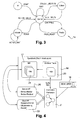
Figure 2 is a finite state machine diagram illustrating in more detail the online profiling and modelling stage of the control system shown inFigure 1 , -
Figure 3 is a finite state machine diagram illustrating in more detail the operation controller of the control system shown inFigure 1 , and -
Figure 4 is a diagram illustrating an example IP (Internet Protocol) Multimedia Subsystem (IMS) network within which the controller system shown inFigure 1 is used. - The inventors realised that an automation framework may be provided that is able to autonomously profile and model a complex telecommunications service running in an arbitrary Cloud platform. This model is used to automatically control (in other words operate) such a Cloud-based service (sometimes known as a cloudified service).
- The inventors realised that an approach of automated modelling based on observed measurement data could be used. They realised it was possible, when generating the system model, to use different model families as a baseline and then find the one that best adjusts to the service under evaluation. In the case of a telecommunications service, the resulting model contains attributes such as the different dependencies between the virtual network functions (VNFs) in the service, or how many Cloud entities (also known as Cloud instances) (where VNFs reside) should be running at each moment for any given input or workload. The model is then used to control the service and accurately decide on the right number of Cloud instances needed at any moment. The inventors realised that this model-based control allows bottlenecks to be avoided by enlarging the dynamic operation area through scaling when required.
- As shown in
Figure 1 , theautomation framework 2 consists of amodelling controller 4 connected to an operation controller 6. - The
automation framework 2, also known as an automaton or a control system, requires as input basic information about the service and the expected performance. This information includes the expected Service Level Agreement, type of traffic (for example SIP, RTP or HTTP), and basic information about connectivity of virtual network functions (VNFs). Theautomation framework 2 may be considered as divided into four stages, namely an On-line Profiling-and-Modelling stage 8, a Model-Optimisation-and-Reduction stage 10, an Interference-Modelling stage 12 and model-based-Operation 14. - The
modelling controller 4 includes the On-line-Profiling-and-Modelling stage 8, the Model-Optimisation-and-Reduction stage 10, and the Interference-Modelling stage 12. Theoperation controller 8 provides the model-based-operation stage 14. - Before considering them in more detail, let us first summarise these four stages as follows:
- 1) In the Online-Profiling-and-
Modelling stage 8, various tests are made to learn the service behaviour/model and its limits (i.e. the operational domain within which the service behaves as expected) for various traffic types. To run these tests, the Online-Profiling-and-Modelling stage 8 of themodelling controller 4 uses workloads of actual traffic or existing pre-recorded traffic, or generates other workloads that are put on the service at specific times. In this phase, the Online-Profiling-and-Modelling stage 8 stresses the service and learns about how metrics of the different virtual network functions (VNFs) evolve with respect to the varied load. For example, service metrics are captured in order to detect the occurance of service errors. At the end of this phase themodelling controller 2 has a number of models that describe the VNF behaviour for the injected workloads. - 2) In the model optimisation and
reduction stage 10, the models and limits obtained in the first phase are combined and generalized for arbitrary workloads. - 3) In the
Interference Modelling stage 12, the accuracy of the models is evaluated against a set of heterogeneous workloads. The interference is measured for different workload combinations and included in the model. - 4) In the operation controller 6, model-based operation occurs in which where the
automation framework 2 operates the service using the determined model. This operation is meant to keep the service inside the limits of the operational domain so that no bottlenecks occur. Therefore, the controller 6 will act on the service every time a Cloud instance is close to a bottleneck, for example by scaling out the number of Cloud instances of a virtual network function (VNF) so as to enlarge its operational domain of expected behaviour. To explain more generally, after the service model is learnt the automaton is able to operate the service and determine in good time when and how to scale up (increase the resources assigned to Cloud entities), scale out (increase the number of Cloud entities) or scale down (i.e., decrease the aggregated capacity) of the service. - We turn now to consider these four stages in more detail.
- In this example the
automation framework 2 is run on System Identification (SID) mode, where SID is an approach that consists of evaluating different model families typically based on regressions such as Autoregressive model (ARX), Autoregressive moving -average model (ARMAX), Box-Jenkins, Non-linear Autoregressive moving -average model (NARMAX), etc. and finding the model family that best adjusts to the real service. - The on-line profiling and modelling stage 8 (in other words the model generating stage or automaton for model generation) is shown as a finite state machine in
Figure 2. Figure 2 will now be described below where we describe within parentheses the name of the transition from one state to another. - As shown in
Figure 2 , when the automaton is started and ready (START), the automaton moves to the System Identification (SID) state andphase 1, namely online profiling and modelling, is started by invoking the injection of a workload (INJECT∥REINJECT) that moves the automaton to the injector state. The automaton waits (INJECTOR_WAIT) for the injector to be ready until the workload is actually being injected (TGEN_OK) and then goes back to the SID state. From there, SID passes to the monitor state (COLLECT_METRICS) in order to wait for measurements that indicate the system reaction to the injected workload. When new data samples arrive, the automaton goes back (NEW_METERS) to SID. This logic is repeated until an arbitrary number of samples N have been collected (N depends on the specific algorithm use to derive the service model from the collected metrics). Not all the metrics are modelled as this would cause excessive and unnecessary complexity. Only relevant metrics are considered by analyzing their variation with the workload (e.g. those with more correlated variation and higher relevance). - SID computes the model of a particular metric for each combination of {virtual network function(VNF), workload, model family (ARX, ARMAX,etc.)}. In this way, the model is improved and updated on-line after N samples have been collected during the execution of the input workload.
- The process is repeated for an arbitrary number of workloads and the outcome of
phase 1 consists of a number of models that are function of such workloads. Therefore, an INJECT_NEXT transition is generated at the end of each workload until all the workloads have been executed. - It is important to note that if the limit of any instance (saturation or bottleneck) is reached during the execution of a workload, the automaton transitions (SYS_LIMIT) from SID to the dependencies state. Here, the automaton stores the amount of load that the bottlenecked instance was able to handle before reaching such bottleneck, and which instance became saturated so as to cause the bottleneck. In addition, it also stores the amount of Cloud instances of each VNF type as well as information of the Cloud instances' resource usage for this amount of load. This information is later used to scale the system with the right number of instances. After updating the dependencies (DEP_UPDATED) the logic returns to SID and the VNF(s) that caused the bottleneck is scaled, see SCALE transition towards the scaling state. The automaton waits for the scaling operation to finish (SCALING_WAIT), stores information such as the time it takes for the scaling VNF to scale, and returns to SID (SCALE_READY). Once back to SID, it will ask to REINJECT the current workload or to INJECT the next one.
- As also shown in
Figure 2 , once all the workloads have been run, the automaton transitions (OPTIMIZE) to the Model Optimisation and Reduction (MOR) state. Here,phase 2, namely the model optimisation and reduction stage, starts and the models are reduced and generalized (REDUCE_MODELS) in the redux state. The input of redux is a model for each combination of {Family_model, traffic_type, workload, VNF, selected_metrics}. Redux combines the different metrics per workload and VNF, reducing the number of models to the combinations of {Family_model, traffic_type, VNF}. That is, the automaton attempts to find a model (or a reduced number of models) for all types of traffic. - As also shown in
Figure 2 , the next step is choosing the final model per VNF and type of traffic. The framework moves to eval (EVAL_MODELS)state. Here, the framework uses the second set of workloads to validate and choose the final model per VNF. The automaton moves iteratively between eval, injector, monitor and scale, while these workloads are being injected, samples are collected and the system is scaled when bottlenecks (limits) occur. Once all the workloads have been injected, the framework performs a comparison between the samples collected and the results obtained by the different models to find the model with the smallest error (e.g. the one with the lowest Mean Absolute Percentage Error, MAPE) per VNF and a transition (MODELS_READY) is generated to indicate the end ofphase 2. - Phase 3 (namely interference modelling) of the automaton is aimed at finding the interferences produced by heterogeneous workloads i.e. mixes and combinations of individual workloads of various traffic types. As a result, the automaton will determine whether the service and its VNFs can be modelled as the aggregation of the models obtained for the various traffic types or a corrective factor is required. The automaton will move iteratively between interf, injector, monitor and scale while the heterogeneous workloads are injected, samples are collected and the service scaled when required. After different workloads combination or mixes have been injected, a comparison between the observed samples and the expected results from the models is performed. These results will rule whether a corrective factor is required on any VNF for any combination of workloads. Once these factors have been computed, a transition (INTERF_READY) returns the automaton to MOR and finishes
Phase 3. - Here the automaton has learnt a model, and it is able to operate the system automatically in the model-based operation phase (phase 4). Referring back to
Figure 1 , the operation is accomplished by an independent operation automaton 14 (namely in the operation controller 6). The finite state machine designed to control/operate the service is shown inFigure 3 . - As shown in
Figure 3 , theoperation automaton 14 requires the following inputs: i) the system and service metrics used during the modelling phase; and ii) the departure and traffic rates of the service. This information is required in order to actuate dynamically on the service with enough time in advance. - The
operation automaton 14 moves to the control state (START) from init state, when the model and the service itself are ready. First, theautomaton 14 moves to collect (COLLECT_METRICS) state, where service metrics and the current incoming and departure rates for each type of traffic are collected and sent to control (NEW_INPUTS). The operation needs to take actions ahead of time, moving to prediction (NEW_PRED) state it looks for a prediction of the amount of load that the service should expect in a time T. This prediction is based on time series analysis of the input and departure rates during the last K timeslots. The time T that the operation automaton looks ahead can be computed as T= max(Ti)+t, being max(Ti) the maximum time the framework needs to instantiate an instance of a VNF; and t some extra manoeuvring time that can be set up by the user. Once the prediction is computed, theautomaton 14 goes back to control (PRED_READY). With the current metrics of the service and the service model, theoperation automaton 14 calculates the number of instances of each VNF needed to serve the predicted load. The number of Cloud instances of each VNF is computed by using the model and the amount of expected load. Then, the resulting number of Cloud instances is enough to ensure that the service remains inside the limits of expected behaviour of the operational area. If any instance is to be added or removed, theoperation automaton 14 moves to actuate (SCALE) state and undertakes the orchestration action that is needed (scale out, down). Theautomaton 14 then waits for this action to be completed (ACTION_WAIT), and moves back to control (ACTION_TAKEN). Finally, theoperation automaton 14 waits for the next timeslot (WAIT), where the next iteration of the control loop will take place. - An example of the automation framework in use is shown in the
Figure 4 . - As shown in
Figure 4 , a given user 16 (a telecom operator or developer in this example) wants to deploy a service (for example IP Multimedia Subsystem, IMS) 17 in theCloud Infrastructure 18. - Referring to
Figure 4 , the automation framework 2' requests thedeveloper 16 to provide basic information about the service(s) he wants to deploy, namely: workload types (e.g., audio, video traffic or instant messages in the IMS example), virtual network functions, VNFs (e.g., Call Server, Packet Interface Module, SCM, etc.), and Service Level Agreements, SLAs (for example as to in what circumstances 'service unavailable' responses (e.g. error code "503") might be expected due to overload and which metrics of quality of service are to be used corresponding to the SLAs). With this basic information, the framework generates a set of traffic workloads for the profiling experiments to be performed, initially one workload per traffic type. Then, for each workload, the automation framework 2' performs an orientated profiling and modelling of the service as described above. This is done in this example by using a dedicated workload tester (or workload generator) 20 as shown infigure 4 . For example, workload is increased and the indicators of 'service unavailable' ("503" errors) for example are monitored to understand whether a limit has been reached. In other similar examples, existing production data relating to traffic, and/or historical data, may be used. - The automation framework 2' connects to the Service and Cloud application programming interface (API'S). The framework uses those APIs in order to:
- i) collect resources metrics (e.g. CPU, MEM, Disk, network), as well as service metrics (e.g., 503 responses and number of processed calls) related to quality of service, for example as defined in Service Level Agreements (SLAs) - this information is used during the creation of models that relate workload to resource utilization;
- ii) once the models are created, reduced and evaluated, the operation controller 6 of the automation framework 2' acts to communicate to a Cloud Application Programming Interface (API) 22 in order to adjust ("right-size", "scale", "grow/de-grow") the amount of Cloud resources, for example the number of Cloud entities (for example Virtual Machines (VMs) or containers), needed to handle the incoming traffic in the model-based operation 14 (phase 4) as described in the previous section. This process determine the amount of resources required by the service in order to provide the correct quality of service, in other words to meet the agreed SLAs, for any arrival rate, and then, perform scalability operations with enough time in advance so that the new Cloud entities 24 (for example virtual machines, VMs) are up and running before the resources in the service are exhausted, minimizing SLA violations.
- Let us consider the flow of information in the scenario in which the
developer 16 wants to deploy an IMS service into aCloud infrastructure 18. The automation framework 2' can be considered to have the fourstages Figure 1 , in other words be divided into four phases as described above. Additionally, more specifically in this example the following applies. - In the on-line profiling and modelling stage (in other words in phase1), various models are created for each of the service's traffic types (previously requested by/for the user). For example, traffic types of messaging, audio, and video are considered. During this phase, the framework 2' generates several workloads for each traffic type and communicates to the
workload tester 20 that is in charge of injecting/reinjecting the workload to the service. Once the workload is injected, the framework '2 then communicates to theCloud Infrastructure 18 andservice APIs 26 in order to monitor resource and service metrics. These metrics are used for the creation of online models that relate each metric to the input workload. - In the model optimisation and reduction stage (in other words phase 2), the framework 2' evaluates the different models created and selects the most accurate one by comparing their Mean Absolute Percentage Error, MAPE (which is a known formula to analyze the error of the model).
- In the Interference Modelling stage, in
other words phase 3, a new set of workloads are injected, where, in this case, the workloads are composed of various traffic mixes with the intention of capturing the interference when different proportions of traffic types are injected into the service at the same time, similar to Phase1. In this phase, the framework 2' also connects to theCloud 18 and theservice APIs 26 in order to enrich and validate the model defined inPhase 2 with an interference factor. - Finally, in the model-based operations stage, in
other words phase 4, the model that has been created is used to calculate the arrival rate of the traffic mix to dynamically calculate the amount ofCloud entities 24 needed to cope with that traffic. Additionally in this phase, the automation framework 2' constantly performs a model validation in the background to catch new model aspects that come from unknown traffic. - Instead of IMS, some other examples could be for cloudified services of the following types: Content Distribution Networks, oneApp, other multitier services (e.g. traditional web-based services).
- The present invention may be embodied in other specific forms without departing from its essential characteristics. For example, the automation framework may be deployed within an application. The described embodiments are to be considered in all respects only as illustrative and not restrictive. The scope of the invention is, therefore, indicated by the appended claims rather than by the foregoing description. All changes that come within the meaning and range of equivalency of the claims are to be embraced within their scope.
- A person skilled in the art would readily recognize that steps of various above-described methods could be performed by programmed computers. Some embodiments relate to program storage devices, e.g., digital data storage media, which are machine or computer readable and encode machine-executable or computer-executable programs of instructions, wherein said instructions perform some or all of the steps of said above-described methods. The program storage devices may be, e.g., digital memories, magnetic storage media such as a magnetic disks and magnetic tapes, hard drives, or optically readable digital data storage media. Some embodiments involve computers programmed to perform said steps of the above-described methods.
Claims (15)
- A controller for a Cloud based service handling multiple types of traffic in a telecommunications network, the controller comprising:a first stage configured to automatically model use of Cloud resources allocated to the service for specific workloads of each of a plurality of traffic types, so as provide a plurality of models for each traffic type;a second stage configured to automatically reduce the number of and generalise the models so as to provided generalised models for each traffic type applicable to other workloads than the specific workloads;a third stage configured to automatically evaluate accuracy of the generalised models for various combinations of given workloads, in each combination each of the given workloads being of a corresponding traffic type, and to select one of the generalised models dependent upon evaluated accuracy; anda fourth stage configured to control operation of the Cloud resources according to the selected model.
- A controller according to claim 1, in which the third stage is also configured to adapt the selected model by at least one correction factor dependent on the combinations of workloads.
- A controller according to claim 1 or claim 2, in which the third stage identifies workload ranges within which the service operates without additional Cloud resources.
- A controller according to any preceding claim, in which the controller instructs adjustment of the Cloud resources provided by Cloud entities for the service dependent upon workloads anticipated for the service.
- A controller according to claim 4, in which in operating the Cloud resources the controller instructs adjustment of the Cloud resources provided by the Cloud entities for the service dependent upon the selected model and the workloads anticipated for the service.
- A controller according to claim 4 or claim 5, in which the controller instructs adjustment of the Cloud resources by instructing at least one of increasing resources assigned to cloud entities and increasing the number of cloud entities, or at least one of decreasing resources assigned to cloud entities and decreasing the number of cloud entities.
- A controller according to claim 6, in which the controller instructs at least one of increasing resources assigned to cloud entities and increasing the number of cloud entities, in the event that a throughput bottleneck is anticipated for the service.
- A controller according to any preceding claim, in which the service is provided by virtual network functions, VNFs, each having at least one corresponding Cloud entity.
- A controller according to any preceding claim, in which said traffic types comprise messaging, audio and video traffic types.
- A controller according to any preceding claim, in which the controller is connected to, and configured to control, a workload tester which is operative to apply the workloads to the Cloud resources and send data to the controller.
- A controller according to any preceding claim, in which the controller uses resource data and service data to provide the models which relate workload to Cloud resource usage.
- A controller according to claim 11, in which the resource data comprises at least some of CPU utilisation and memory utilisation, disk space, and network configuration; and the service data comprises at least one of number of error messages indicating overload in a period and number of calls processed in a period.
- A controller according to claim 11 or claim 12, in which the third stage is configured to receive the data from at least one or both of, a Cloud Application Programming Interface and a Service Application Programming Interface, to adapt the reduced number of generalised models to provide the selected model.
- A controller according to any preceding claim, in which the service is an Internet Protocol, IP, Multimedia Subsystem, IMS, service.
- A method of providing a Cloud based service handling multiple types of traffic in a telecommunications network, the method comprising:automatically modelling use of Cloud resources allocated to the service for specific workloads of each of a plurality of traffic types, so as provide a variety of models for each traffic type;automatically reducing the number of, and generalising, the models so as to provide generalised models for each traffic type applicable to other workloads than the specific workloads;automatically evaluating accuracy of the generalised models for various combinations of given workloads, in each combination each of the given workloads being of a corresponding traffic type, and selecting one of the generalised models dependent upon evaluated accuracy; andoperating the Cloud resources according to the selected model.
Priority Applications (4)
| Application Number | Priority Date | Filing Date | Title |
|---|---|---|---|
| EP15306988.5A EP3179699B1 (en) | 2015-12-11 | 2015-12-11 | A controller for a cloud based service in a telecommunications network, and a method of providing a cloud based service |
| US16/060,675 US10862766B2 (en) | 2015-12-11 | 2016-12-09 | Controller for a cloud based service in a telecommunications network, and a method of providing a cloud based service |
| PCT/EP2016/080467 WO2017097992A1 (en) | 2015-12-11 | 2016-12-09 | A controller for a cloud based service in a telecommunications network, and a method of providing a cloud based service |
| CN201680079921.9A CN108496338B (en) | 2015-12-11 | 2016-12-09 | Controller for cloud-based service in telecommunication network and method of providing cloud-based service |
Applications Claiming Priority (1)
| Application Number | Priority Date | Filing Date | Title |
|---|---|---|---|
| EP15306988.5A EP3179699B1 (en) | 2015-12-11 | 2015-12-11 | A controller for a cloud based service in a telecommunications network, and a method of providing a cloud based service |
Publications (2)
| Publication Number | Publication Date |
|---|---|
| EP3179699A1 true EP3179699A1 (en) | 2017-06-14 |
| EP3179699B1 EP3179699B1 (en) | 2020-05-27 |
Family
ID=55077374
Family Applications (1)
| Application Number | Title | Priority Date | Filing Date |
|---|---|---|---|
| EP15306988.5A Active EP3179699B1 (en) | 2015-12-11 | 2015-12-11 | A controller for a cloud based service in a telecommunications network, and a method of providing a cloud based service |
Country Status (4)
| Country | Link |
|---|---|
| US (1) | US10862766B2 (en) |
| EP (1) | EP3179699B1 (en) |
| CN (1) | CN108496338B (en) |
| WO (1) | WO2017097992A1 (en) |
Cited By (1)
| Publication number | Priority date | Publication date | Assignee | Title |
|---|---|---|---|---|
| WO2019127452A1 (en) * | 2017-12-29 | 2019-07-04 | Nokia Technologies Oy | Virtualized network functions |
Families Citing this family (9)
| Publication number | Priority date | Publication date | Assignee | Title |
|---|---|---|---|---|
| US10700946B2 (en) * | 2017-08-08 | 2020-06-30 | Amdocs Development Limited | System, method, and computer program for automatically certifying a virtual network function (VNF) for use in a network function virtualization (NFV) based communication network |
| US10764113B2 (en) * | 2018-07-05 | 2020-09-01 | At&T Intellectual Property I, L.P. | Self-adjusting control loop |
| US11379254B1 (en) * | 2018-11-18 | 2022-07-05 | Pure Storage, Inc. | Dynamic configuration of a cloud-based storage system |
| US10880173B2 (en) | 2018-12-03 | 2020-12-29 | At&T Intellectual Property I, L.P. | Automated certification of network functions |
| CN109918275B (en) * | 2019-01-17 | 2022-09-16 | 珠海金山网络游戏科技有限公司 | Method, device and system for realizing pressure test on server performance |
| US11562299B2 (en) * | 2019-06-18 | 2023-01-24 | Vmware, Inc. | Workload tenure prediction for capacity planning |
| CN110472875A (en) * | 2019-08-20 | 2019-11-19 | 北京百度网讯科技有限公司 | Method and apparatus for generating information |
| CN114666223B (en) * | 2020-12-04 | 2023-11-21 | 中国移动通信集团设计院有限公司 | Cloud computing resource pool processing method and device and readable storage medium |
| CN112631860A (en) * | 2020-12-21 | 2021-04-09 | 常州微亿智造科技有限公司 | Industrial Internet of things data transmission Worker service monitoring method and device |
Citations (2)
| Publication number | Priority date | Publication date | Assignee | Title |
|---|---|---|---|---|
| EP2615803A2 (en) * | 2012-01-13 | 2013-07-17 | Accenture Global Services Limited | Performance interference model for managing consolidated workloads in QoS-aware clouds |
| US20150326535A1 (en) * | 2014-05-07 | 2015-11-12 | Verizon Patent And Licensing Inc. | Network platform-as-a-service for creating and inserting virtual network functions into a service provider network |
Family Cites Families (12)
| Publication number | Priority date | Publication date | Assignee | Title |
|---|---|---|---|---|
| US7146356B2 (en) | 2003-03-21 | 2006-12-05 | International Business Machines Corporation | Real-time aggregation of unstructured data into structured data for SQL processing by a relational database engine |
| US7146353B2 (en) * | 2003-07-22 | 2006-12-05 | Hewlett-Packard Development Company, L.P. | Resource allocation for multiple applications |
| CN101937359A (en) | 2010-08-19 | 2011-01-05 | 中国船舶重工集团公司第七○九研究所 | A General and Scalable Computing System for Simulation Applications |
| US9679029B2 (en) * | 2010-11-08 | 2017-06-13 | Globalfoundries Inc. | Optimizing storage cloud environments through adaptive statistical modeling |
| CN102256266B (en) * | 2011-07-04 | 2014-06-04 | 重庆邮电大学 | User application-oriented adaptive access network selection device and method |
| US20130185729A1 (en) | 2012-01-13 | 2013-07-18 | Rutgers, The State University Of New Jersey | Accelerating resource allocation in virtualized environments using workload classes and/or workload signatures |
| US9363154B2 (en) * | 2012-09-26 | 2016-06-07 | International Business Machines Corporaion | Prediction-based provisioning planning for cloud environments |
| WO2014071084A2 (en) * | 2012-10-31 | 2014-05-08 | O'malley, Matt | System and method for dynamically monitoring, analyzing, managing, and alerting packet data traffic and applications |
| CN103403682B (en) | 2012-11-23 | 2017-03-15 | 华为技术有限公司 | A logical object deployment method, related device and system |
| JP6237318B2 (en) * | 2014-02-19 | 2017-11-29 | 富士通株式会社 | Management device, workload distribution management method, and workload distribution management program |
| CN104301403B (en) | 2014-09-26 | 2017-09-26 | 东北大学 | Cloud service dynamic resource allocation system and method based on Component service copy additions and deletions |
| US20160328273A1 (en) * | 2015-05-05 | 2016-11-10 | Sap Se | Optimizing workloads in a workload placement system |
-
2015
- 2015-12-11 EP EP15306988.5A patent/EP3179699B1/en active Active
-
2016
- 2016-12-09 US US16/060,675 patent/US10862766B2/en active Active
- 2016-12-09 CN CN201680079921.9A patent/CN108496338B/en active Active
- 2016-12-09 WO PCT/EP2016/080467 patent/WO2017097992A1/en not_active Ceased
Patent Citations (2)
| Publication number | Priority date | Publication date | Assignee | Title |
|---|---|---|---|---|
| EP2615803A2 (en) * | 2012-01-13 | 2013-07-17 | Accenture Global Services Limited | Performance interference model for managing consolidated workloads in QoS-aware clouds |
| US20150326535A1 (en) * | 2014-05-07 | 2015-11-12 | Verizon Patent And Licensing Inc. | Network platform-as-a-service for creating and inserting virtual network functions into a service provider network |
Non-Patent Citations (1)
| Title |
|---|
| RASHID MIJUMBI ET AL: "Network Function Virtualization: State-of-the-art and Research Challenges", IEEE COMMUNICATIONS SURVEYS & TUTORIALS, 26 January 2015 (2015-01-26), XP055239665, Retrieved from the Internet <URL:http://www.maps.upc.edu/rashid/files/NFVSURVEY.pdf> [retrieved on 20160108] * |
Cited By (2)
| Publication number | Priority date | Publication date | Assignee | Title |
|---|---|---|---|---|
| WO2019127452A1 (en) * | 2017-12-29 | 2019-07-04 | Nokia Technologies Oy | Virtualized network functions |
| US11663027B2 (en) | 2017-12-29 | 2023-05-30 | Nokia Technologies Oy | Virtualized network functions |
Also Published As
| Publication number | Publication date |
|---|---|
| US20180278485A1 (en) | 2018-09-27 |
| CN108496338B (en) | 2021-02-02 |
| US10862766B2 (en) | 2020-12-08 |
| WO2017097992A1 (en) | 2017-06-15 |
| EP3179699B1 (en) | 2020-05-27 |
| CN108496338A (en) | 2018-09-04 |
Similar Documents
| Publication | Publication Date | Title |
|---|---|---|
| US10862766B2 (en) | Controller for a cloud based service in a telecommunications network, and a method of providing a cloud based service | |
| US11373123B2 (en) | System and method for designing and executing control loops in a cloud environment | |
| US11310113B2 (en) | Methods, systems and apparatus to improve cluster efficiency | |
| Pérez et al. | Assessing sla compliance from palladio component models | |
| US9268663B1 (en) | Software testing analysis and control | |
| US11461685B2 (en) | Determining performance in a distributed application or system | |
| US11461669B2 (en) | Runtime prediction for a job of a workflow | |
| Incerto et al. | Software performance self-adaptation through efficient model predictive control | |
| CN103383655B (en) | For the performance interference model for the workload that merging is managed in perceiving cloud in QOS | |
| Hiessl et al. | Optimal placement of stream processing operators in the fog | |
| CN108595250B (en) | A resource scheduling efficiency optimization method and system for IaaS cloud platform | |
| US11689641B2 (en) | Resiliency control engine for network service mesh systems | |
| US20210184925A1 (en) | Model-driven technique for virtual network function rehoming for service chains | |
| Makridis et al. | Robust dynamic CPU resource provisioning in virtualized servers | |
| Pérez et al. | Line: Evaluating software applications in unreliable environments | |
| Wang et al. | Enhancing performance modeling of serverless functions via static analysis | |
| Barna et al. | Cloud adaptation with control theory in industrial clouds | |
| Chardet et al. | Predictable efficiency for reconfiguration of service-oriented systems with concerto | |
| Iglesias et al. | Orca: an orchestration automata for configuring vnfs | |
| KR20250021452A (en) | Methods and systems for managing robotic process automation | |
| Willnecker et al. | Optimization of deployment topologies for distributed enterprise applications | |
| Sun et al. | A model-based system to automate cloud resource allocation and optimization | |
| Walter et al. | Online learning of run-time models for performance and resource management in data centers | |
| Rygielski et al. | Flexible performance prediction of data center networks using automatically generated simulation models | |
| Yousaf et al. | RAVA—Resource aware VNF agnostic NFV orchestration method for virtualized networks |
Legal Events
| Date | Code | Title | Description |
|---|---|---|---|
| PUAI | Public reference made under article 153(3) epc to a published international application that has entered the european phase |
Free format text: ORIGINAL CODE: 0009012 |
|
| STAA | Information on the status of an ep patent application or granted ep patent |
Free format text: STATUS: THE APPLICATION HAS BEEN PUBLISHED |
|
| AK | Designated contracting states |
Kind code of ref document: A1 Designated state(s): AL AT BE BG CH CY CZ DE DK EE ES FI FR GB GR HR HU IE IS IT LI LT LU LV MC MK MT NL NO PL PT RO RS SE SI SK SM TR |
|
| AX | Request for extension of the european patent |
Extension state: BA ME |
|
| STAA | Information on the status of an ep patent application or granted ep patent |
Free format text: STATUS: REQUEST FOR EXAMINATION WAS MADE |
|
| 17P | Request for examination filed |
Effective date: 20171214 |
|
| RBV | Designated contracting states (corrected) |
Designated state(s): AL AT BE BG CH CY CZ DE DK EE ES FI FR GB GR HR HU IE IS IT LI LT LU LV MC MK MT NL NO PL PT RO RS SE SI SK SM TR |
|
| RAP1 | Party data changed (applicant data changed or rights of an application transferred) |
Owner name: ALCATEL LUCENT |
|
| RIN1 | Information on inventor provided before grant (corrected) |
Inventor name: SIENEL, JURGEN Inventor name: HILT, VOLKER Inventor name: RIEMER, JOACHIM Inventor name: BRAUN, STEFANIE Inventor name: OMANA IGLESIAS, JESUS Inventor name: ARJONA AROCA, JORDI Inventor name: VOITH, THOMAS Inventor name: LUGONES, DIEGO |
|
| STAA | Information on the status of an ep patent application or granted ep patent |
Free format text: STATUS: EXAMINATION IS IN PROGRESS |
|
| 17Q | First examination report despatched |
Effective date: 20191204 |
|
| GRAP | Despatch of communication of intention to grant a patent |
Free format text: ORIGINAL CODE: EPIDOSNIGR1 |
|
| STAA | Information on the status of an ep patent application or granted ep patent |
Free format text: STATUS: GRANT OF PATENT IS INTENDED |
|
| RIC1 | Information provided on ipc code assigned before grant |
Ipc: G06F 9/455 20180101ALI20200211BHEP Ipc: H04L 29/08 20060101AFI20200211BHEP Ipc: H04L 12/24 20060101ALI20200211BHEP Ipc: H04L 12/26 20060101ALI20200211BHEP |
|
| INTG | Intention to grant announced |
Effective date: 20200228 |
|
| GRAS | Grant fee paid |
Free format text: ORIGINAL CODE: EPIDOSNIGR3 |
|
| GRAA | (expected) grant |
Free format text: ORIGINAL CODE: 0009210 |
|
| STAA | Information on the status of an ep patent application or granted ep patent |
Free format text: STATUS: THE PATENT HAS BEEN GRANTED |
|
| AK | Designated contracting states |
Kind code of ref document: B1 Designated state(s): AL AT BE BG CH CY CZ DE DK EE ES FI FR GB GR HR HU IE IS IT LI LT LU LV MC MK MT NL NO PL PT RO RS SE SI SK SM TR |
|
| REG | Reference to a national code |
Ref country code: GB Ref legal event code: FG4D |
|
| REG | Reference to a national code |
Ref country code: CH Ref legal event code: EP |
|
| REG | Reference to a national code |
Ref country code: AT Ref legal event code: REF Ref document number: 1275756 Country of ref document: AT Kind code of ref document: T Effective date: 20200615 |
|
| REG | Reference to a national code |
Ref country code: DE Ref legal event code: R096 Ref document number: 602015053291 Country of ref document: DE |
|
| REG | Reference to a national code |
Ref country code: LT Ref legal event code: MG4D |
|
| PG25 | Lapsed in a contracting state [announced via postgrant information from national office to epo] |
Ref country code: IS Free format text: LAPSE BECAUSE OF FAILURE TO SUBMIT A TRANSLATION OF THE DESCRIPTION OR TO PAY THE FEE WITHIN THE PRESCRIBED TIME-LIMIT Effective date: 20200927 Ref country code: FI Free format text: LAPSE BECAUSE OF FAILURE TO SUBMIT A TRANSLATION OF THE DESCRIPTION OR TO PAY THE FEE WITHIN THE PRESCRIBED TIME-LIMIT Effective date: 20200527 Ref country code: PT Free format text: LAPSE BECAUSE OF FAILURE TO SUBMIT A TRANSLATION OF THE DESCRIPTION OR TO PAY THE FEE WITHIN THE PRESCRIBED TIME-LIMIT Effective date: 20200928 Ref country code: SE Free format text: LAPSE BECAUSE OF FAILURE TO SUBMIT A TRANSLATION OF THE DESCRIPTION OR TO PAY THE FEE WITHIN THE PRESCRIBED TIME-LIMIT Effective date: 20200527 Ref country code: GR Free format text: LAPSE BECAUSE OF FAILURE TO SUBMIT A TRANSLATION OF THE DESCRIPTION OR TO PAY THE FEE WITHIN THE PRESCRIBED TIME-LIMIT Effective date: 20200828 Ref country code: NO Free format text: LAPSE BECAUSE OF FAILURE TO SUBMIT A TRANSLATION OF THE DESCRIPTION OR TO PAY THE FEE WITHIN THE PRESCRIBED TIME-LIMIT Effective date: 20200827 Ref country code: LT Free format text: LAPSE BECAUSE OF FAILURE TO SUBMIT A TRANSLATION OF THE DESCRIPTION OR TO PAY THE FEE WITHIN THE PRESCRIBED TIME-LIMIT Effective date: 20200527 |
|
| REG | Reference to a national code |
Ref country code: NL Ref legal event code: MP Effective date: 20200527 |
|
| PG25 | Lapsed in a contracting state [announced via postgrant information from national office to epo] |
Ref country code: RS Free format text: LAPSE BECAUSE OF FAILURE TO SUBMIT A TRANSLATION OF THE DESCRIPTION OR TO PAY THE FEE WITHIN THE PRESCRIBED TIME-LIMIT Effective date: 20200527 Ref country code: BG Free format text: LAPSE BECAUSE OF FAILURE TO SUBMIT A TRANSLATION OF THE DESCRIPTION OR TO PAY THE FEE WITHIN THE PRESCRIBED TIME-LIMIT Effective date: 20200827 Ref country code: LV Free format text: LAPSE BECAUSE OF FAILURE TO SUBMIT A TRANSLATION OF THE DESCRIPTION OR TO PAY THE FEE WITHIN THE PRESCRIBED TIME-LIMIT Effective date: 20200527 Ref country code: HR Free format text: LAPSE BECAUSE OF FAILURE TO SUBMIT A TRANSLATION OF THE DESCRIPTION OR TO PAY THE FEE WITHIN THE PRESCRIBED TIME-LIMIT Effective date: 20200527 |
|
| REG | Reference to a national code |
Ref country code: AT Ref legal event code: MK05 Ref document number: 1275756 Country of ref document: AT Kind code of ref document: T Effective date: 20200527 |
|
| PG25 | Lapsed in a contracting state [announced via postgrant information from national office to epo] |
Ref country code: AL Free format text: LAPSE BECAUSE OF FAILURE TO SUBMIT A TRANSLATION OF THE DESCRIPTION OR TO PAY THE FEE WITHIN THE PRESCRIBED TIME-LIMIT Effective date: 20200527 Ref country code: NL Free format text: LAPSE BECAUSE OF FAILURE TO SUBMIT A TRANSLATION OF THE DESCRIPTION OR TO PAY THE FEE WITHIN THE PRESCRIBED TIME-LIMIT Effective date: 20200527 |
|
| PG25 | Lapsed in a contracting state [announced via postgrant information from national office to epo] |
Ref country code: ES Free format text: LAPSE BECAUSE OF FAILURE TO SUBMIT A TRANSLATION OF THE DESCRIPTION OR TO PAY THE FEE WITHIN THE PRESCRIBED TIME-LIMIT Effective date: 20200527 Ref country code: EE Free format text: LAPSE BECAUSE OF FAILURE TO SUBMIT A TRANSLATION OF THE DESCRIPTION OR TO PAY THE FEE WITHIN THE PRESCRIBED TIME-LIMIT Effective date: 20200527 Ref country code: SM Free format text: LAPSE BECAUSE OF FAILURE TO SUBMIT A TRANSLATION OF THE DESCRIPTION OR TO PAY THE FEE WITHIN THE PRESCRIBED TIME-LIMIT Effective date: 20200527 Ref country code: DK Free format text: LAPSE BECAUSE OF FAILURE TO SUBMIT A TRANSLATION OF THE DESCRIPTION OR TO PAY THE FEE WITHIN THE PRESCRIBED TIME-LIMIT Effective date: 20200527 Ref country code: IT Free format text: LAPSE BECAUSE OF FAILURE TO SUBMIT A TRANSLATION OF THE DESCRIPTION OR TO PAY THE FEE WITHIN THE PRESCRIBED TIME-LIMIT Effective date: 20200527 Ref country code: AT Free format text: LAPSE BECAUSE OF FAILURE TO SUBMIT A TRANSLATION OF THE DESCRIPTION OR TO PAY THE FEE WITHIN THE PRESCRIBED TIME-LIMIT Effective date: 20200527 Ref country code: RO Free format text: LAPSE BECAUSE OF FAILURE TO SUBMIT A TRANSLATION OF THE DESCRIPTION OR TO PAY THE FEE WITHIN THE PRESCRIBED TIME-LIMIT Effective date: 20200527 Ref country code: CZ Free format text: LAPSE BECAUSE OF FAILURE TO SUBMIT A TRANSLATION OF THE DESCRIPTION OR TO PAY THE FEE WITHIN THE PRESCRIBED TIME-LIMIT Effective date: 20200527 |
|
| PG25 | Lapsed in a contracting state [announced via postgrant information from national office to epo] |
Ref country code: PL Free format text: LAPSE BECAUSE OF FAILURE TO SUBMIT A TRANSLATION OF THE DESCRIPTION OR TO PAY THE FEE WITHIN THE PRESCRIBED TIME-LIMIT Effective date: 20200527 Ref country code: SK Free format text: LAPSE BECAUSE OF FAILURE TO SUBMIT A TRANSLATION OF THE DESCRIPTION OR TO PAY THE FEE WITHIN THE PRESCRIBED TIME-LIMIT Effective date: 20200527 |
|
| REG | Reference to a national code |
Ref country code: DE Ref legal event code: R097 Ref document number: 602015053291 Country of ref document: DE |
|
| PLBE | No opposition filed within time limit |
Free format text: ORIGINAL CODE: 0009261 |
|
| STAA | Information on the status of an ep patent application or granted ep patent |
Free format text: STATUS: NO OPPOSITION FILED WITHIN TIME LIMIT |
|
| 26N | No opposition filed |
Effective date: 20210302 |
|
| PG25 | Lapsed in a contracting state [announced via postgrant information from national office to epo] |
Ref country code: SI Free format text: LAPSE BECAUSE OF FAILURE TO SUBMIT A TRANSLATION OF THE DESCRIPTION OR TO PAY THE FEE WITHIN THE PRESCRIBED TIME-LIMIT Effective date: 20200527 |
|
| REG | Reference to a national code |
Ref country code: CH Ref legal event code: PL |
|
| PG25 | Lapsed in a contracting state [announced via postgrant information from national office to epo] |
Ref country code: MC Free format text: LAPSE BECAUSE OF FAILURE TO SUBMIT A TRANSLATION OF THE DESCRIPTION OR TO PAY THE FEE WITHIN THE PRESCRIBED TIME-LIMIT Effective date: 20200527 |
|
| REG | Reference to a national code |
Ref country code: BE Ref legal event code: MM Effective date: 20201231 |
|
| PG25 | Lapsed in a contracting state [announced via postgrant information from national office to epo] |
Ref country code: FR Free format text: LAPSE BECAUSE OF NON-PAYMENT OF DUE FEES Effective date: 20201231 Ref country code: LU Free format text: LAPSE BECAUSE OF NON-PAYMENT OF DUE FEES Effective date: 20201211 Ref country code: IE Free format text: LAPSE BECAUSE OF NON-PAYMENT OF DUE FEES Effective date: 20201211 |
|
| REG | Reference to a national code |
Ref country code: DE Ref legal event code: R079 Ref document number: 602015053291 Country of ref document: DE Free format text: PREVIOUS MAIN CLASS: H04L0029080000 Ipc: H04L0065000000 |
|
| PG25 | Lapsed in a contracting state [announced via postgrant information from national office to epo] |
Ref country code: LI Free format text: LAPSE BECAUSE OF NON-PAYMENT OF DUE FEES Effective date: 20201231 Ref country code: CH Free format text: LAPSE BECAUSE OF NON-PAYMENT OF DUE FEES Effective date: 20201231 |
|
| PG25 | Lapsed in a contracting state [announced via postgrant information from national office to epo] |
Ref country code: TR Free format text: LAPSE BECAUSE OF FAILURE TO SUBMIT A TRANSLATION OF THE DESCRIPTION OR TO PAY THE FEE WITHIN THE PRESCRIBED TIME-LIMIT Effective date: 20200527 Ref country code: MT Free format text: LAPSE BECAUSE OF FAILURE TO SUBMIT A TRANSLATION OF THE DESCRIPTION OR TO PAY THE FEE WITHIN THE PRESCRIBED TIME-LIMIT Effective date: 20200527 Ref country code: CY Free format text: LAPSE BECAUSE OF FAILURE TO SUBMIT A TRANSLATION OF THE DESCRIPTION OR TO PAY THE FEE WITHIN THE PRESCRIBED TIME-LIMIT Effective date: 20200527 |
|
| PG25 | Lapsed in a contracting state [announced via postgrant information from national office to epo] |
Ref country code: MK Free format text: LAPSE BECAUSE OF FAILURE TO SUBMIT A TRANSLATION OF THE DESCRIPTION OR TO PAY THE FEE WITHIN THE PRESCRIBED TIME-LIMIT Effective date: 20200527 |
|
| PG25 | Lapsed in a contracting state [announced via postgrant information from national office to epo] |
Ref country code: BE Free format text: LAPSE BECAUSE OF NON-PAYMENT OF DUE FEES Effective date: 20201231 |
|
| PGFP | Annual fee paid to national office [announced via postgrant information from national office to epo] |
Ref country code: DE Payment date: 20251104 Year of fee payment: 11 |
|
| PGFP | Annual fee paid to national office [announced via postgrant information from national office to epo] |
Ref country code: GB Payment date: 20251030 Year of fee payment: 11 |