EP3179650A1 - Wireless communication system, base station, mobile station, transmission method, and demodulation method - Google Patents
Wireless communication system, base station, mobile station, transmission method, and demodulation method Download PDFInfo
- Publication number
- EP3179650A1 EP3179650A1 EP14899153.2A EP14899153A EP3179650A1 EP 3179650 A1 EP3179650 A1 EP 3179650A1 EP 14899153 A EP14899153 A EP 14899153A EP 3179650 A1 EP3179650 A1 EP 3179650A1
- Authority
- EP
- European Patent Office
- Prior art keywords
- antennas
- base station
- group
- reference signal
- data signal
- Prior art date
- Legal status (The legal status is an assumption and is not a legal conclusion. Google has not performed a legal analysis and makes no representation as to the accuracy of the status listed.)
- Withdrawn
Links
Images



Classifications
-
- H—ELECTRICITY
- H04—ELECTRIC COMMUNICATION TECHNIQUE
- H04L—TRANSMISSION OF DIGITAL INFORMATION, e.g. TELEGRAPHIC COMMUNICATION
- H04L5/00—Arrangements affording multiple use of the transmission path
- H04L5/003—Arrangements for allocating sub-channels of the transmission path
- H04L5/0048—Allocation of pilot signals, i.e. of signals known to the receiver
-
- H—ELECTRICITY
- H04—ELECTRIC COMMUNICATION TECHNIQUE
- H04B—TRANSMISSION
- H04B7/00—Radio transmission systems, i.e. using radiation field
- H04B7/02—Diversity systems; Multi-antenna system, i.e. transmission or reception using multiple antennas
- H04B7/04—Diversity systems; Multi-antenna system, i.e. transmission or reception using multiple antennas using two or more spaced independent antennas
- H04B7/0413—MIMO systems
- H04B7/0456—Selection of precoding matrices or codebooks, e.g. using matrices antenna weighting
- H04B7/046—Selection of precoding matrices or codebooks, e.g. using matrices antenna weighting taking physical layer constraints into account
- H04B7/0473—Selection of precoding matrices or codebooks, e.g. using matrices antenna weighting taking physical layer constraints into account taking constraints in layer or codeword to antenna mapping into account
-
- H—ELECTRICITY
- H04—ELECTRIC COMMUNICATION TECHNIQUE
- H04B—TRANSMISSION
- H04B7/00—Radio transmission systems, i.e. using radiation field
- H04B7/02—Diversity systems; Multi-antenna system, i.e. transmission or reception using multiple antennas
- H04B7/04—Diversity systems; Multi-antenna system, i.e. transmission or reception using multiple antennas using two or more spaced independent antennas
- H04B7/0413—MIMO systems
- H04B7/0456—Selection of precoding matrices or codebooks, e.g. using matrices antenna weighting
- H04B7/046—Selection of precoding matrices or codebooks, e.g. using matrices antenna weighting taking physical layer constraints into account
- H04B7/0469—Selection of precoding matrices or codebooks, e.g. using matrices antenna weighting taking physical layer constraints into account taking special antenna structures, e.g. cross polarized antennas into account
-
- H—ELECTRICITY
- H04—ELECTRIC COMMUNICATION TECHNIQUE
- H04B—TRANSMISSION
- H04B7/00—Radio transmission systems, i.e. using radiation field
- H04B7/02—Diversity systems; Multi-antenna system, i.e. transmission or reception using multiple antennas
- H04B7/04—Diversity systems; Multi-antenna system, i.e. transmission or reception using multiple antennas using two or more spaced independent antennas
- H04B7/0413—MIMO systems
- H04B7/0456—Selection of precoding matrices or codebooks, e.g. using matrices antenna weighting
- H04B7/0478—Special codebook structures directed to feedback optimisation
- H04B7/0479—Special codebook structures directed to feedback optimisation for multi-dimensional arrays, e.g. horizontal or vertical pre-distortion matrix index [PMI]
-
- H—ELECTRICITY
- H04—ELECTRIC COMMUNICATION TECHNIQUE
- H04L—TRANSMISSION OF DIGITAL INFORMATION, e.g. TELEGRAPHIC COMMUNICATION
- H04L25/00—Baseband systems
- H04L25/02—Details ; arrangements for supplying electrical power along data transmission lines
- H04L25/0202—Channel estimation
- H04L25/0204—Channel estimation of multiple channels
-
- H—ELECTRICITY
- H04—ELECTRIC COMMUNICATION TECHNIQUE
- H04L—TRANSMISSION OF DIGITAL INFORMATION, e.g. TELEGRAPHIC COMMUNICATION
- H04L25/00—Baseband systems
- H04L25/02—Details ; arrangements for supplying electrical power along data transmission lines
- H04L25/0202—Channel estimation
- H04L25/0224—Channel estimation using sounding signals
-
- H—ELECTRICITY
- H04—ELECTRIC COMMUNICATION TECHNIQUE
- H04L—TRANSMISSION OF DIGITAL INFORMATION, e.g. TELEGRAPHIC COMMUNICATION
- H04L5/00—Arrangements affording multiple use of the transmission path
- H04L5/0001—Arrangements for dividing the transmission path
- H04L5/0014—Three-dimensional division
- H04L5/0023—Time-frequency-space
-
- H—ELECTRICITY
- H04—ELECTRIC COMMUNICATION TECHNIQUE
- H04L—TRANSMISSION OF DIGITAL INFORMATION, e.g. TELEGRAPHIC COMMUNICATION
- H04L5/00—Arrangements affording multiple use of the transmission path
- H04L5/0091—Signalling for the administration of the divided path, e.g. signalling of configuration information
-
- H—ELECTRICITY
- H04—ELECTRIC COMMUNICATION TECHNIQUE
- H04B—TRANSMISSION
- H04B7/00—Radio transmission systems, i.e. using radiation field
- H04B7/02—Diversity systems; Multi-antenna system, i.e. transmission or reception using multiple antennas
- H04B7/04—Diversity systems; Multi-antenna system, i.e. transmission or reception using multiple antennas using two or more spaced independent antennas
- H04B7/06—Diversity systems; Multi-antenna system, i.e. transmission or reception using multiple antennas using two or more spaced independent antennas at the transmitting station
- H04B7/0613—Diversity systems; Multi-antenna system, i.e. transmission or reception using multiple antennas using two or more spaced independent antennas at the transmitting station using simultaneous transmission
- H04B7/0615—Diversity systems; Multi-antenna system, i.e. transmission or reception using multiple antennas using two or more spaced independent antennas at the transmitting station using simultaneous transmission of weighted versions of same signal
- H04B7/0619—Diversity systems; Multi-antenna system, i.e. transmission or reception using multiple antennas using two or more spaced independent antennas at the transmitting station using simultaneous transmission of weighted versions of same signal using feedback from receiving side
- H04B7/0621—Feedback content
- H04B7/063—Parameters other than those covered in groups H04B7/0623 - H04B7/0634, e.g. channel matrix rank or transmit mode selection
Definitions
- the present invention relates to a wireless communications system, a base station, a mobile station, a transmission method, and a demodulation method.
- Non-Patent Literature 1 A 3-D channel model in the standardization of Release 12 of the LTE is being studied (see, e.g., Non-Patent Literature 2 below).
- Non-Patent Literature 1 " Study on 3D-channel model for Elevation Beamforming and FD-MIMO studies for LTE", 3GPPTM Work Item Description, Dec. 2012
- Non-Patent Literature 2 " 3rd Generation Partnership Project; Technical Specification Group Radio Access Network; Study on 3D channel model for LTE (Release 12)", 3GPP TR 36.873 V1.1.1, 2013-09
- an object of the present invention is to suppress increases in the amount of control information and to suppress increases in the radio resources used in the transmission a reference signal.
- a wireless communications system transmits, by a group of antennas arranged two-dimensionally along a first direction and a second direction, a data signal weighted for respective antennas of the group of antennas; weight a first reference signal corresponding to the data signal and transmit the first reference signal for each mobile station of mobile stations with which communication is performed, the first reference signal being transmitted by a first plurality of antennas included in the group of antennas and arranged along the first direction; transmit without executing weighting for each antenna, a second reference signal that is common to the mobile stations with which communication is performed, the second reference signal being transmitted by a second plurality of antennas included in the group of antennas and arranged along the second direction at positions corresponding to some antennas of the first plurality of antennas; transmit weight information indicating a weight for the data signal at antennas included in the group of antennas and arranged along the second direction; and demodulate the
- increases in the amount of the control information and in the radio resources used in the transmission of a reference signal may be suppressed.
- FIG. 1 is an explanatory diagram of an example of a functional configuration of a wireless communications system.
- a wireless communications system 100 includes a base station 110 and a mobile station 120.
- the base station 110 includes a transmitting unit 111.
- the transmitting unit 111 transmits by a group 112 of antennas, a data signal for which weighting for each of the antennas is executed.
- the group 112 of antennas is arranged in two dimensions of a first direction and a second direction.
- the "first direction” and the “second direction” are directions different from each other.
- the first direction is a horizontal direction (a direction of "A” in FIG. 1 ) and the second direction is a vertical direction (a direction of "B” in FIG. 1 ).
- the first direction and the second direction are not limited to these directions and, for example, the first direction may be set to be the vertical direction and the second direction may be set to be the horizontal direction.
- the group 112 of antennas includes first plural antennas 113 arranged along the first direction, and second plural antennas 114 arranged along the second direction at positions corresponding to some antennas 113a of the first plural antennas 113.
- the first plural antennas 113 are aligned in a single line in the horizontal direction.
- the second plural antennas 114 are aligned in a single line in the vertical direction.
- the transmitting unit 111 transmits by the first plural antennas 113, a first reference signal weighted corresponding to the data signal, for each mobile station 120 to be the transmission destination.
- the first reference signal is a reference signal specific to the mobile station 120.
- the transmitting unit 111 transmits a second reference signal common to the mobile stations 120 to be the transmission destinations, to the mobile stations 120 by the second plural antennas 114 without weighting the second reference signal for each of the antennas.
- the second reference signal is a reference signal common in one cell formed by, for example, the base station 110.
- the second plural antennas 114 are not included among the first plural antennas 113, the arrangement thereof is not limited hereto and the antennas may be included among the first plural antennas 113 as denoted by a reference numeral "115". In this case, the reference signals merely have to be transmitted using the radio resources at different times and at different frequencies.
- the transmitting unit 111 transmits weight information that indicates the weight for a data signal for each of the antennas arranged in the second direction.
- the weight information is, for example, precoding information of the vertical direction.
- the transmitting unit 111 does not transmit the first reference signal or the second reference signal by antennas 116 that are different from the first plural antennas 113 or the second plural antennas 114, among the group 112 of antennas.
- the arrangement intervals of at least the antennas in the second direction are relatively small.
- the group 112 of antennas are a group of antennas whose arrangement intervals of the antennas in the second direction are each smaller than one wavelength of a radio signal transmitted from each of the antennas 114, 115, and 116 included in the group 112 of antennas.
- a sharp directivity may be obtained for a beam in the vertical direction.
- Temporal variations attributed to fading in each radio channel are substantially equal to each other and the phase difference of each radio channel depends on the incoming direction of the signal.
- the phase difference of the channel state of another antenna not transmitting the first reference signal therefore, may be also estimated by estimating the phase difference of the radio channel of an antenna adjacent in the vertical direction.
- the mobile station 120 includes a receiving unit 121 and a demodulating unit 122.
- the receiving unit 121 receives the first reference signal, the second reference signal, and the weight information transmitted by the base station 110.
- the receiving unit 121 outputs the received signals and the received weight information to the demodulating unit 122.
- the demodulating unit 122 demodulates the data signal transmitted by the base station 110 based on the first reference signal, the second reference signal, and the weight information received by the receiving unit 121.
- the demodulating unit 122 estimates the phase difference of the channel state between the antennas arranged in the second direction of the group 112 of antennas, based on the second reference signal. For example, the demodulating unit 122 compares the estimation results of the channel state based on the second reference signal transmitted by the second plural antennas 114, and estimates the phase difference of the channel state between the antennas arranged in the second direction based on the result of the comparison of the estimation results with each other.
- the demodulating unit 122 estimates a distortion component for the data signal transmitted by the group 112 of antennas based on the estimation result of the channel state, based on the first reference signal, the estimated phase difference, and the weight information.
- the demodulating unit 122 demodulates the data signal based on the estimated distortion component.
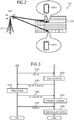
- FIG. 2 is an explanatory diagram of an example of a configuration of a wireless communications system.
- a wireless communications system 200 includes an evolved node B (eNB) 210 and mobile stations 220.
- eNB evolved node B
- the wireless communications system 100 of FIG. 1 is realized by the wireless communications system 200; the base station 110 of FIG. 1 is realized by the eNB 210; and the mobile station 120 of FIG. 1 is realized by the mobile station 220.
- the eNB 210 is a multi-antenna base station and a base station of the LTE.
- the LTE is a communication standard of the 3rd Generation Partnership Project (3GPP) that is a standard-setting organization.
- 3GPP 3rd Generation Partnership Project
- the eNB 210 is wirelessly connected to an upper network and is also wirelessly connected to the mobile stations 220.
- the mobile stations 220 are each a user apparatus such as a mobile phone or a smartphone.
- the mobile stations 220a and 220b are positioned, for example, at positions at different heights in a building 230.
- the mobile stations 220 are able communicate with the eNB 210 even when the mobile stations 220 are not positioned in the building 230.
- MIMO is employed.
- MIMO is a technique of transmitting and receiving plural data streams using plural antennas at a time.
- the number of spatially multiplexed data streams is adaptively controlled.
- Precoding is executed for MIMO transmission of the LTE.
- the precoding is control on the transmitter side and takes the fading condition into consideration, and is to multiply by a predetermined weight, the transmission signal before being transmitted from the antenna.
- a directional beam may adaptively be formed for the mobile station by executing the precoding and, as a result, the electric power of the received signal at the mobile station may be increased. For example, some patterns are determined in advance according to the specification for the weight used in the precoding.
- the mobile station 220 measures the fading condition and selects the best precoding pattern based on the measured fading condition.
- the mobile station 220 feeds back the precoding pattern to the eNB 210.
- the feedback signal is a precoding matrix indicator (PMI).
- the wireless communications system 200 forms the directional beams for the horizontal and the vertical directions by the multiple antennas arranged in the two-dimensional array and, for example, the 3D-MIMO or the full dimension-MIMO (FD-MIMO) is employed.
- the 3D-MIMO or the full dimension-MIMO FD-MIMO
- the gain of the cell division may be obtained by virtually forming sectors in an elevation angle direction in addition to the fixed formation of sectors in the horizontal direction.
- FIG. 3 is a sequence diagram of an example of a procedure for processing between apparatuses executed by the wireless communications system.
- the eNB 210 transmits a channel state information-reference signal (CSI-RS) to the mobile station 220 (in FIG. 3 , user equipment (UE)) (step S301).
- CSI-RS is a signal to execute measurement of the quality.
- the mobile station 220 calculates the CSI (the channel quality) (step S302) and transmits the calculated CSI to the eNB 210 (step S303).
- the CSI transmitted from the mobile station 220 to the eNB 210 includes a channel quality indicator (CQI), a precoding matrix indicator (PMI), and a rank indicator (RI).
- CQI channel quality indicator
- PMI precoding matrix indicator
- RI rank indicator
- the eNB 210 executes the precoding using these pieces of information (step S304).
- the eNB 210 transmits a UE-specific reference signal (RS) to the mobile station 220 (step S305).
- the eNB 210 applies the same precoding matrix to a physical downlink shared channel (PDSCH) and the UE-specific RS to transmit the PDSCH and the UE-specific RS to the mobile station 220.
- the first reference signal is realized by, for example, the UE-specific RS.
- the mobile station 220 executes channel estimation of calculating the channel estimation value based on the UE-specific RS (step S306).
- the eNB 210 transmits the PDSCH that is a downlink shared channel (step S307).
- the mobile station 220 demodulates the PDSCH using the channel estimation value calculated at step S306 (step S308) and the series of process steps comes to an end.
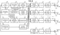
- FIG. 4 is a functional block diagram of an example of the eNB.
- the eNB 210 includes a precoding determining unit 401, a control signal generating unit 402, a UE-specific RS generating unit 403, a second precoding processing unit 404, a first antenna mapping unit 405, a common demodulation-reference signal (common DM-RS) generating unit 406, a second antenna mapping unit 407, a user scheduler unit 408, a data signal generating unit 409, and a first precoding processing unit 410.
- a precoding determining unit 401 the eNB 210 includes a precoding determining unit 401, a control signal generating unit 402, a UE-specific RS generating unit 403, a second precoding processing unit 404, a first antenna mapping unit 405, a common demodulation-reference signal (common DM-RS) generating unit 406, a second antenna mapping unit 407, a user scheduler unit 408, a data signal generating unit 4
- the eNB 210 also includes physical channel multiplexing units 411, inverse fast Fourier transform (IFFT) units 412, transmission radio frequency (RF) units 413, transmission antennas 414, a reception antenna 415, a reception RF unit 416, a fast Fourier transform (FFT) unit 417, and an uplink control signal demodulating unit 418.
- IFFT inverse fast Fourier transform
- RF transmission radio frequency
- FFT fast Fourier transform
- the precoding determining unit 401 determines precoding matrix information based on the PMI output from the uplink control signal demodulating unit 418.
- the precoding determining unit 401 outputs the determined information to the control signal generating unit 402, the second precoding processing unit 404, the user scheduler unit 408, and the first precoding processing unit 410.
- the precoding determining unit 401 outputs the precoding information (the weight information) for the vertical direction and antenna port (AP) information for the UE-specific RS, to the control signal generating unit 402.
- the AP information corresponds to a data stream.
- the precoding determining unit 401 outputs the precoding information for the horizontal direction to the second precoding processing unit 404.
- the precoding determining unit 401 outputs the precoding information for the horizontal direction and for the vertical direction to the first precoding processing unit 410.
- the precoding determining unit 401 outputs the precoding matrix information to the user scheduler unit 408.
- the control signal generating unit 402 generates a control signal that includes the precoding information for the vertical direction and the AP information of the UE-specific RS to be applied to the mobile station 220, using the information output from the precoding determining unit 401.
- the control signal generating unit 402 outputs the generated control signal to the physical channel multiplexing unit 411.
- the UE-specific RS generating unit 403 generates the UE-specific RS and outputs the UE-specific RS to the second precoding processing unit 404.
- the second precoding processing unit 404 executes a precoding process for the UE-specific RS output from the UE-specific RS generating unit 403, using the precoding information for the horizontal direction output from the precoding determining unit 401.
- the second precoding processing unit 404 outputs the UE-specific RS for which the precoding process is executed, to the first antenna mapping unit 405.
- the first antenna mapping unit 405 executes mapping on the (plural) transmission antennas 414 in one specific row arranged in the horizontal direction for transmission of the UE-specific RS.
- the first antenna mapping unit 405 outputs the UE-specific RS for which the mapping is executed, to the physical channel multiplexing unit 411.
- the mapping enables the UE-specific RS to be transmitted from the defined transmission antennas 414 and the defined resources for each time (each sub-frame) and each frequency (each physical resource block).
- the common DM-RS generating unit 406 generates the common DM-RS that is the reference signal common in one cell formed by the base station 110 and used when the mobile station 220 demodulates data, and outputs the generated common DM-RS to the second antenna mapping unit 407.
- the second reference signal is realized by, for example, the common DM-RS.
- the second antenna mapping unit 407 executes mapping for the common DM-RS on two transmission antennas 414 arranged in the vertical direction for transmission of the common DM-RS.
- the second antenna mapping unit 407 outputs the common DM-RS for which the mapping is executed, to the physical channel multiplexing unit 411.
- the mapping enables the common DM-RS to be transmitted from the defined transmission antennas 414 and the defined resources for each time (each sub-frame) and each frequency (each PRB).
- the user scheduler unit 408 executes scheduling using the PMI output from the uplink control signal demodulating unit 418 and the precoding matrix information determined by the precoding determining unit 401.
- the user scheduler unit 408 schedules the mobile stations 220 compatible with each other for the precoding to be in one same sub-frame. For example, when concurrent transmission is executed for the plural mobile stations 220 positioned in the same direction, mutual interference may occur and the user scheduler unit 408 therefore combines the plural mobile stations 220 positioned in different directions to schedule these plural mobile stations 220 to be in one same sub-frame.
- the user scheduler unit 408 outputs the scheduling information to the data signal generating unit 409.
- the data signal generating unit 409 generates a data signal using the scheduling information output from the user scheduler unit 408, and outputs the generated data signal to the first precoding processing unit 410.
- the first precoding processing unit 410 executes a precoding process using the data signal output from the data signal generating unit 409 and the precoding information for the horizontal direction and for the vertical direction determined by the data signal generating unit 401.
- the first precoding processing unit 410 outputs the data signal for which the precoding process is executed, to the physical channel multiplexing unit 411.
- the control signal is input from the control signal generating unit 402, the UE-specific RS is input from the first antenna mapping unit 405, the common DM-RS is input from the second antenna mapping unit 407, and the data signal is input from the first precoding processing unit 410.
- the physical channel multiplexing unit 411 multiplexes the various types of signals input thereinto, and outputs a multiplexed signal to a corresponding IFFT unit 412 of the plural IFFT units 412.
- the IFFT unit 412 converts the signal output from the physical channel multiplexing unit 411 into a signal in the time domain, and outputs the converted signal to the corresponding transmission RF unit 413 of the plural transmission RF units 413.
- the transmission RF unit 413 digital to analog (D/A)-converts and carrier-modulates the signal output from the IFFT unit 412 to generate a transmission signal.
- the transmission RF unit 413 outputs the generated transmission signal to the corresponding transmission antenna 414 of the plural (80) transmission antennas 414.
- the transmission antenna 414 wirelessly outputs the transmission signal output from the transmission RF unit 413 as a downlink transmission signal.
- the reception antenna 415 receives the radio signal output from the mobile station 220 and outputs the received radio signal to the reception RF unit 416.
- the reception RF unit 416 removes the carrier and analog to digital (A/D)-converts the signal output from the reception antenna 415, and outputs the converted signal to the FFT unit 417.
- the FFT unit 417 divides the signal output from the reception RF unit 416 into pieces of data of frequency components by Fourier transform and outputs the pieces of data to the uplink control signal demodulating unit 418.
- the uplink control signal demodulating unit 418 extracts the PMI from the pieces of data output from the FFT unit 417 and outputs the PMI to the precoding determining unit 401.
- the transmitting unit 111 depicted in FIG. 1 is realized by, for example, the precoding determining unit 401, the control signal generating unit 402, the UE-specific RS generating unit 403, the second precoding processing unit 404, the first antenna mapping unit 405, the common DM-RS generating unit 406, and the second antenna mapping unit 407.
- the group 112 of antennas depicted in FIG. 1 is realized by the plural transmission antennas 414.
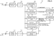
- FIG. 5 is a functional block diagram of an example of the mobile station.
- the mobile station 220 includes a reception antenna 501, a reception RF unit 502, an FFT unit 503, a control signal demodulating unit 504, a channel estimating unit 505, a channel estimating unit 506, a B-component calculating unit 507, a C-component calculating unit 508, a data signal demodulating unit 509, a CSI calculating unit 510, an uplink control signal generating unit 511, an IFFT unit 512, a transmission RF unit 513, and a transmission antenna 514.
- the reception antenna 501 receives the radio signal output from the eNB 210 and outputs the received radio signal to the reception RF unit 502.
- the reception RF unit 502 removes the carrier and A/D-converts the signal output from the reception antenna 501, and outputs the converted signal to the FFT unit 503.
- the FFT unit 503 divides the signal output from the reception RF unit 502 into pieces of data of frequency components by Fourier transform and outputs the pieces of data to the control signal demodulating unit 504, the channel estimating units 505 and 506, the data signal demodulating unit 509, and the CSI calculating unit 510.
- the control signal demodulating unit 504 obtains the precoding information (the weight information) for the vertical direction applied to the mobile station 220 and the AP information of the UE-specific RS from the signal output from the FFT unit 503.
- the control signal demodulating unit 504 outputs the AP information of the UE-specific RS to the channel estimating unit 505.
- the control signal demodulating unit 504 outputs the precoding information for the vertical direction to the B-component calculating unit 507.
- the channel estimating unit 505 obtains an A component of equation (6), described later, by channel estimation based on the UE-specific RS using the signal output from the FFT unit 503 and the AP information output from the control signal demodulating unit 504.
- the channel estimating unit 505 outputs the A component obtained by the channel estimation to the C-component calculating unit 508.
- the channel estimating unit 506 calculates the phase difference ⁇ h ⁇ in the vertical direction between radio channels by the channel estimation based on the common DM-RS using the signal output from the FFT unit 503, and outputs the phase difference ⁇ h ⁇ to the B-component calculating unit 507.
- the B-component calculating unit 507 obtains a B component of equation (6), described later, using the precoding information for the vertical direction output from the control signal demodulating unit 504 and the phase difference ⁇ h ⁇ output from the channel estimating unit 506.
- the B-component calculating unit 507 outputs the calculated B component to the C-component calculating unit 508.
- the C component is a channel distortion component in the PDSCH.
- the C-component calculating unit 508 outputs the calculated C component to the data signal demodulating unit 509.
- the data signal demodulating unit 509 demodulates the PDSCH included in the signal output from the FFT unit 503 using the C component output from the C-component calculating unit 508, and outputs the demodulated PDSCH as user data.
- the CSI calculating unit 510 calculates the CSI (the channel quality) and outputs the CSI to the uplink control signal generating unit 511.
- the uplink control signal generating unit 511 generates an uplink control signal using the CSI output from the CSI calculating unit 510 and outputs the generated uplink control signal to the IFFT unit 512.
- the IFFT unit 512 converts the signal output from the uplink control signal generating unit 511 into a signal in the time domain and outputs the converted signal to the transmission RF unit 513.
- the transmission RF unit 513 D/A-converts and carrier-modulates the signal output from the IFFT unit 512 to generate a transmission signal.
- the transmission RF unit 513 outputs the generated transmission signal to the transmission antenna 514.
- the transmission antenna 514 wirelessly outputs the transmission signal output from the transmission RF unit 513 as an uplink transmission signal.
- the receiving unit 121 depicted in FIG. 1 is realized by the reception RF unit 502, the FFT unit 503, and the like.
- the demodulating unit 122 depicted in FIG. 1 is realized by, for example, the control signal demodulating unit 504, the channel estimating units 505 and 506, the B-component calculating unit 507, the C-component calculating unit 508, and the data signal demodulating unit 509.
- FIG. 6 is an explanatory diagram of an example of the transmission antennas of the eNB.
- the lateral direction represents the horizontal direction and the longitudinal direction represents the vertical direction.
- ANT(0,0) to (7,0) are arranged in the horizontal direction at equal intervals.
- ANT(0,0) to (0,9) are arranged in the vertical direction at equal intervals.
- the antennas other than these are arranged similarly in the respective directions at equal intervals.
- one line in a diagonal direction indicates one antenna and the antennas intersecting with each other indicate that the polarized waves thereof are different from each other.
- ANT(0,0) and ANT(4,0) have polarized waves that are different from each other.
- the intervals of at least the antennas in the vertical direction are relatively small and sharp directivity may therefore be obtained for the beam in the vertical direction.
- the fading correlation becomes significant in the radio channels of the antennas in the vertical direction and the phase difference of each of the radio channels depends on the incoming direction of the signal.
- the radio channel of each of the other antennas not transmitting the RS may therefore be also estimated by estimating the phase difference of the radio channel of an antenna adjacent thereto in the vertical direction.
- the RS is transmitted from ANT(m,0) and ANT(m,1), and the radio channel state of another ANT(m,n) can be estimated based on the phase difference between the radio channels thereof.
- the estimation based on the phase difference is used.
- FIG. 7 is an explanatory diagram of an example of the principle for estimating the radio channel of another antenna.
- ANT(m,0), ANT(m,1), ANT(m,2), ..., ANT(m,n) are arranged in the vertical direction.
- the common DM-RS is transmitted from ANT(m,0) and ANT(m,1), and the radio channel of another ANT(m,n) may be estimated based on the phase difference ⁇ h ⁇ between the radio channels thereof.
- the radio channel may be represented by equations (1) and (2) below.
- “h” represents the phase.
- “d” represents each of the intervals of the antennas in the vertical direction.
- “ ⁇ ” represents the angle against the mobile station 220.
- “ ⁇ ” represents the wavelength of the signal.
- the difference is the phase difference ⁇ h ⁇ between the phase of the common DM-RS received by the mobile station 220 from ANT(m,n-1) and the phase of the common DM-RS received by the mobile station 220 from ANT(m,n).
- the radio channel state of other antennas may be estimated by using this principle.
- Equation (4) represents the definition of the radio channel from each of the transmission antennas.
- the distortion component C (the C component) in the PDSCH received by the mobile station 220 may be represented by equation (6) below using the phase difference ⁇ h ⁇ between the antennas.
- the "A component” corresponds to the distortion at the mobile station 220 in a case where a signal to which the antenna weights (the precoding) in the horizontal direction is applied is transmitted from the antennas in the highest row (ANT(0,0) to (7,0)).
- the A component can be obtained by the channel estimation for the UE-specific RS.
- the B component is obtained using the weight information of the antennas in the vertical direction (the precoding information for the vertical direction) and the phase difference ⁇ h ⁇ between the radio channels.
- the C component is obtained by multiplying the A component by the B component.
- Equation (1) and equation (2) represent an example where ⁇ h ⁇ is calculated between ANT(m,0) and ANT(m,1) that is adjacent thereto in the vertical direction while, not limiting to this, ⁇ h ⁇ may also be calculated between ANT(m,0) and ANT that is not adjacent thereto. This case will be described.
- the right side of equation (3) above may be represented as "-exp(-j ⁇ )" as a function of ⁇ .
- the phase difference h m ⁇ n /h m,0 of the radio channel between ANT(m,0) and ANT(m,n) may be represented as in equation (7) below.
- ⁇ h ⁇ may therefore be represented as in equation (9) below.
- ⁇ h v exp j n arg h 8 ⁇ n h 0
- ⁇ h ⁇ may therefore be calculated even when antennas away from each other are used.
- Equation (10) below is considered as a variation of the above conditional equation.
- the phase difference between the radio channels may be obtained even when the antennas used are away from each other within a range for the conditional equation of equation (10) above to be satisfied.
- ⁇ h ⁇ can also be calculated using ANT(m,0) and ANT(m,3).
- FIG. 8 is an explanatory diagram of an example of a signal transmitted from the eNB and the transmission antennas transmitting the signal.
- the antennas (ANT(0,0) to (7,0)) in the highest row transmit the UE-specific RS to which the antenna weights for the horizontal direction are applied.
- the ANT(0,8) and ANT(0,9) transmit the common DM-RS to which no antenna weight is applied.
- FIG. 9 is an explanatory diagram of an example of the sub-frame configuration and mapping with PRB.
- a radio resource can be assigned to a user such as that whose 12 sub-carriers (180 kHz) adjacent to each other in the frequency direction at intervals of each 15 kHz are sectioned as one PRB that is further sectioned by each 1 ms in the time direction.
- OFDMA orthogonal frequency division multiplex access
- the physical channels and the signals are mapped on the PRB.
- Types of the physical channel include the PDSCH, a physical control format indicator channel (PCFICH), a physical HARQ indicator channel (PHICH), and a physical downlink control channel (PDCCH).
- PCFICH physical control format indicator channel
- PHICH physical HARQ indicator channel
- PDCCH physical downlink control channel
- the PCFICH is a channel to notify how many symbols at the head of each sub-frame are reserved as a region capable of transmitting downlink control information.
- the PHICH is a channel to transmit delivery acknowledgement information (ACK/NACK) for a physical uplink shared channel (PUSCH).
- the PUSCH is a shared data channel to transmit uplink user data.
- the PDCCH is used to give notification of the assignment information of the radio resources to the user selected by the eNB 210 based on the scheduling.
- the precoding information for the vertical direction (the weight information) is transmitted using, for example, the PDCCH.
- such signals are assigned as the cell-specific RS specific to the cell and the UE-specific RS specific to the user, and CSI-RS.
- code-multiplexing is executed for the UE-specific RS.
- "1" of the UE-specific RS is present in each of four consecutive resource elements (four boxes) and can code-multiplex four APs (APs 7, 8, 11, and 13).
- An orthogonal code is used for the code-multiplexing.
- boxes of "2" of the UE-specific RS are present on four consecutive resource elements (the four boxes) and can multiplex four APs (AP 9, 10, 12, and 14). As above, the eight APs are supported for the UE-specific RS.
- the common DM-RS is assigned to the positions at each of which the PDSCH is assigned.
- the UE-specific RS for the horizontal direction may concurrently transmit eight types of AP of AP7 to 14.
- AP information is information that designates which one of the eight types is used to execute the channel estimation.
- the AP information is information for the mobile station 220 to know which type of orthogonal code is used for recovery, because four types of orthogonal code are multiplexed by the eNB 210.
- the APs of the UE-specific RS is increased corresponding to the number of multiplexed codes.
- the eNB 210 transmits the RS (the UE-specific RS) specific to the mobile station 220 from the group 112 of antennas in the horizontal direction and transmits the RS (the common DM-RS) common to the mobile stations 220 from the group 112 of antennas in the vertical direction.
- the recovery of the data is therefore enabled and the resources may be reduced even when the common DM-RS common to the mobile stations 220 is not transmitted from all the transmission antennas 414.
- the eNB 210 enables scheduling of the PDSCHs to be in one same sub-frame for a combination of UEs that are compatible with each other to avoid any interference during the concurrent transmission.
- the eNB 210 transmits the CSI-RS to the plural mobile stations 220 (UE1 and UE2) (step S1001).
- the CSI-RS is the signal to execute the quality measurement and is a signal common to UE1 and UE2.
- the mobile station 220 calculates the CSI (the channel quality) (step S1002) and transmits the calculated CSI to the eNB 210 (step S1003).
- the CSI differs for each of the mobile stations 220.
- the CSI includes a channel quality indicator (CQI), a precoding matrix indicator (PMI), and a rank indicator (RI).
- the eNB 210 determines the precoding using these pieces of information (step S1004) and executes user scheduling (step S1005).
- the eNB 210 transmits downlink control information (DCI) to each of the mobile stations 220 (step S1006).
- DCI downlink control information
- the DCI is different between UE1 and UE2.
- the DCI includes information concerning the antenna weight Wv n for the vertical direction represented in 3 bits and information concerning the AP to be used in the transmission of the UE-specific RS.
- the eNB 210 transmits the UE-specific RS to the mobile stations 220 (step S1007).
- the UE-specific RS differs between UE1 and UE2.
- the UE-specific RS is a signal of which there are up to eight types and to which the precoding for the horizontal direction is applied from the transmission antennas 414 arranged in the horizontal direction and in a specific row.
- the mobile station 220 calculates the A component by the channel estimation by the UE-specific RS (step S1008).
- the eNB 210 transmits the common DM-RS to the mobile stations 220 (step S1009).
- the common DM-RS is a signal common to UE1 and UE2.
- the common DM-RS is a signal to which the precoding is not applied from the two transmission antennas 414 arranged in the vertical direction.
- the mobile station 220 calculates the B component from the channel component by the common DM-RS (step S1010).
- the mobile station 220 calculates the phase difference ⁇ h ⁇ between the radio channels by the channel estimation in the common DM-RS and obtains the B component by using the information on the antenna weight Wv n included in the DCI.
- the mobile station 220 calculates the C component that is the channel distortion component in the PDSCH by using the A component and the B component (step S1011).
- the eNB 210 transmits the PDSCH to the mobile stations 220 (step S1012).
- the mobile station 220 demodulates the PDSCH using the received PDSCH and the calculated C component (step S1013) and the series of process steps come to an end.
- FIG. 11 is an explanatory diagram of an example of the user scheduling.
- exemplary combinations 1100 represent examples as to what type of multiplexing may be executed including the plural types of physical channels.
- the UEs subject to the multiplexing are 64 that are UE1 to 64.
- the "Precoding for PDSCH” represents a case where both of the horizontal and the vertical ones are applied, and 64 types thereof are present.
- "(0)" and "(1)" of "Precoding for PDSCH" represent indexes for the precoding.
- the "Precoding for UE-Specific RS” represents only the horizontal component and represents any one of W H (0) to W H (7).
- the "AP for UE-specific RS” represents by which AP the UE-specific RS is transmitted and represents any one of APs AP7 to AP14. A different resource is used corresponding to the precoding pattern for the "AP for UE-specific RS”. Notification of the "AP for UE-specific RS" is given by the DCI.
- the "Precoding Information for Vertical Direction” that is to be notified has an index number of the antenna weight Wv for the vertical direction and represents any one of 0 to 7. Notification of the "AP for UE-specific RS” is given by the DCI.
- the horizontal direction PMI (W 1 ) is set to be 4 bits
- the horizontal direction PMI (W 2 ) is set to be 4 bits
- the vertical direction PMI is set to be 3 bits.
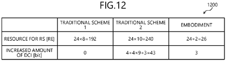
- a "Traditional Scheme 1” represents a case where the RS for the demodulation is configured only by the UE-specific RS.
- the orthogonal time and frequency resources of the amount corresponding to the number of the multiplexing sessions of the MU-MIMO are necessary.
- “24” in this calculation equation represents the number of the resource elements of the UE-specific RS (24 boxes) represented by "1" and "2" of FIG. 9 .
- " 8 " in the calculation equation represents "8” based on the fact that the number of the multiplexing sessions of the MU-MIMO is set to be 8 times.
- the increased amount of the DCI is zero in the traditional scheme 1.
- a “Traditional Scheme 2” represents a case where the RS for the demodulation is configured only by the common DM-RS.
- the orthogonal time and frequency resources of the amount corresponding to the number of the antennas of the transmission antennas 414 are necessary. Notification of the information concerning the precoding needs to be given to the mobile stations 220. In particular, the amount of the information concerning the horizontal component is large because this information is present for each of the sub-bands.
- “24” in this calculation equation represents the number of the resource elements of the UE-specific RS (24 boxes) represented by "1" and “2” of FIG. 9 .
- “ 10 " in this calculation equation represents "10” that is based on the fact that the number of the antennas is 10 times as many as the original number thereof in the vertical direction.
- "4" at the leftmost term of this calculation equation represents “4" that is based on the fact that the horizontal direction PMI (W 1 ) is 4 bits.
- "4" of "4x9” of this calculation equation represents “4" that is based on the fact that the horizontal direction PMI (W 2 ) is 4 bits.
- "9" of "4 ⁇ 9” of this calculation equation represents the number of the sub-bands.
- “3” of this calculation equation represents “3” that is based on the fact that the vertical direction PMI is 3 bits.
- “24” in this calculation equation represents the number of the resource elements of the UE-specific RS (24 boxes) represented by “1" and “2" of FIG. 9 .
- “ 2 " in the calculation equation represents the number of the resource elements of the common DM-RS (2 boxes) of FIG. 9 .
- the increased amount of the DCI is "3 bits". These "3 bits" correspond to the information amount of the antenna weight Wv n in the vertical direction.
- increase of the RS resources and increase of the DCI can be suppressed even when the number of the antennas is set to be 80, the number of the multiplexing sessions of the MU-MIMO is set to be 64, and the number of the sub-bands is set to be 9.
- the eNB 210 transmits the UE-specific RS specific to each of the mobile stations 120 from the horizontally arranged first plural antennas 113 and transmits the common DM-RS common to the mobile stations 120 from the vertically arranged second plural antennas 114 to give notification of the weight information for the vertical direction.
- the mobile station 220 estimates the phase difference ⁇ h ⁇ of the channel state between the antennas arranged in the vertical direction based on the common DM-RS.
- the mobile station 220 estimates the distortion component (the C component) for the data signal based on the estimation result of the channel state based on the UE-specific RS, the estimated phase difference ⁇ h ⁇ , and the weight information, and demodulates the data signal based on the estimated distortion component.
- the mobile station 220 may therefore demodulate the data and may suppress increase of the radio resources used in the transmission of the reference signals and suppress increase of the amount of the control information even when the RS is not transmitted from all the antennas of the eNB 210. Increase of the overhead of the radio resources may therefore be suppressed and degradation of the transmission efficiency of the PDSCH may be suppressed.
Landscapes
- Engineering & Computer Science (AREA)
- Signal Processing (AREA)
- Computer Networks & Wireless Communication (AREA)
- Power Engineering (AREA)
- Physics & Mathematics (AREA)
- Mathematical Physics (AREA)
- Mobile Radio Communication Systems (AREA)
- Radio Transmission System (AREA)
Abstract
Description
- The present invention relates to a wireless communications system, a base station, a mobile station, a transmission method, and a demodulation method.
- Related to long term evolution (LTE), techniques have been traditionally known concerning beam forming and "multiple input multiple output (MIMO)" using plural antennas (see, e.g., Non-Patent
Literature 1 below). A 3-D channel model in the standardization ofRelease 12 of the LTE is being studied (see, e.g., Non-PatentLiterature 2 below). - Non-Patent Literature 1: "Study on 3D-channel model for Elevation Beamforming and FD-MIMO studies for LTE", 3GPPTM Work Item Description, Dec. 2012 Non-Patent Literature 2: "3rd Generation Partnership Project; Technical Specification Group Radio Access Network; Study on 3D channel model for LTE (Release 12)", 3GPP TR 36.873 V1.1.1, 2013-09
- However, with the traditional techniques, for example, a reference signal to demodulate data at a receiving side is transmitted from all the antennas and a problem therefore arises in that the radio resources used for the transmission of the reference signal increase when the number of the antennas is increased. To cope with this, although notifying the receiving side of weighting information for all the antennas using control information is conceivable, another problem arises in that the amount of the control information increases.
- In one aspect, an object of the present invention is to suppress increases in the amount of control information and to suppress increases in the radio resources used in the transmission a reference signal.
- According to one aspect of the present invention, a wireless communications system, a base station, a mobile station, a transmission method, and a demodulation method are proposed that: transmit, by a group of antennas arranged two-dimensionally along a first direction and a second direction, a data signal weighted for respective antennas of the group of antennas; weight a first reference signal corresponding to the data signal and transmit the first reference signal for each mobile station of mobile stations with which communication is performed, the first reference signal being transmitted by a first plurality of antennas included in the group of antennas and arranged along the first direction; transmit without executing weighting for each antenna, a second reference signal that is common to the mobile stations with which communication is performed, the second reference signal being transmitted by a second plurality of antennas included in the group of antennas and arranged along the second direction at positions corresponding to some antennas of the first plurality of antennas; transmit weight information indicating a weight for the data signal at antennas included in the group of antennas and arranged along the second direction; and demodulate the data signal transmitted, based on the first reference signal, the second reference signal, and the weight information transmitted.
- According to one aspect of the present invention, increases in the amount of the control information and in the radio resources used in the transmission of a reference signal may be suppressed.
-
-
FIG. 1 is an explanatory diagram of an example of a functional configuration of a wireless communications system; -
FIG. 2 is an explanatory diagram of an example of a configuration of a wireless communications system; -
FIG. 3 is a sequence diagram of an example of a procedure for processing between apparatuses executed by the wireless communications system; -
FIG. 4 is a functional block diagram of an example of an eNB; -
FIG. 5 is a functional block diagram of an example of a mobile station; -
FIG. 6 is an explanatory diagram of an example of transmission antennas of the eNB; -
FIG. 7 is an explanatory diagram of an example of a principle for estimating a radio channel of another antenna; -
FIG. 8 is an explanatory diagram of an example of a signal transmitted from the eNB and the transmission antennas transmitting the signal; -
FIG. 9 is an explanatory diagram of an example of a sub-frame configuration and mapping with PRB; -
FIG. 10 is a sequence diagram of an example of a procedure for demodulating a PDSCH executed by the wireless communications system; -
FIG. 11 is an explanatory diagram of an example of user scheduling; and -
FIG. 12 is an explanatory diagram of an example of a comparison with a traditional case with respect to resource amount. - Preferred embodiments of a disclosed technology will be described in detail with reference to the accompanying drawings.
-
FIG. 1 is an explanatory diagram of an example of a functional configuration of a wireless communications system. As depicted inFIG. 1 , awireless communications system 100 includes abase station 110 and amobile station 120. Thebase station 110 includes a transmittingunit 111. The transmittingunit 111 transmits by agroup 112 of antennas, a data signal for which weighting for each of the antennas is executed. - The
group 112 of antennas is arranged in two dimensions of a first direction and a second direction. The "first direction" and the "second direction" are directions different from each other. For example, the first direction is a horizontal direction (a direction of "A" inFIG. 1 ) and the second direction is a vertical direction (a direction of "B" inFIG. 1 ). The first direction and the second direction are not limited to these directions and, for example, the first direction may be set to be the vertical direction and the second direction may be set to be the horizontal direction. - The
group 112 of antennas includes firstplural antennas 113 arranged along the first direction, and secondplural antennas 114 arranged along the second direction at positions corresponding to someantennas 113a of the firstplural antennas 113. The firstplural antennas 113 are aligned in a single line in the horizontal direction. The secondplural antennas 114 are aligned in a single line in the vertical direction. - The transmitting
unit 111 transmits by the firstplural antennas 113, a first reference signal weighted corresponding to the data signal, for eachmobile station 120 to be the transmission destination. The first reference signal is a reference signal specific to themobile station 120. The transmittingunit 111 transmits a second reference signal common to themobile stations 120 to be the transmission destinations, to themobile stations 120 by the secondplural antennas 114 without weighting the second reference signal for each of the antennas. The second reference signal is a reference signal common in one cell formed by, for example, thebase station 110. - Although the second
plural antennas 114 are not included among the firstplural antennas 113, the arrangement thereof is not limited hereto and the antennas may be included among the firstplural antennas 113 as denoted by a reference numeral "115". In this case, the reference signals merely have to be transmitted using the radio resources at different times and at different frequencies. - The transmitting
unit 111 transmits weight information that indicates the weight for a data signal for each of the antennas arranged in the second direction. The weight information is, for example, precoding information of the vertical direction. The transmittingunit 111 does not transmit the first reference signal or the second reference signal byantennas 116 that are different from the firstplural antennas 113 or the secondplural antennas 114, among thegroup 112 of antennas. - As to the
group 112 of antennas, the arrangement intervals of at least the antennas in the second direction are relatively small. For example, thegroup 112 of antennas are a group of antennas whose arrangement intervals of the antennas in the second direction are each smaller than one wavelength of a radio signal transmitted from each of theantennas group 112 of antennas. A sharp directivity may be obtained for a beam in the vertical direction. When the intervals of the antennas are each small, the fading correlation becomes significant in the radio channels each connecting the antenna and the mobile station. - Temporal variations attributed to fading in each radio channel are substantially equal to each other and the phase difference of each radio channel depends on the incoming direction of the signal. The phase difference of the channel state of another antenna not transmitting the first reference signal, therefore, may be also estimated by estimating the phase difference of the radio channel of an antenna adjacent in the vertical direction.
- The
mobile station 120 includes areceiving unit 121 and a demodulatingunit 122. Thereceiving unit 121 receives the first reference signal, the second reference signal, and the weight information transmitted by thebase station 110. Thereceiving unit 121 outputs the received signals and the received weight information to the demodulatingunit 122. The demodulatingunit 122 demodulates the data signal transmitted by thebase station 110 based on the first reference signal, the second reference signal, and the weight information received by thereceiving unit 121. - For example, the demodulating
unit 122 estimates the phase difference of the channel state between the antennas arranged in the second direction of thegroup 112 of antennas, based on the second reference signal. For example, the demodulatingunit 122 compares the estimation results of the channel state based on the second reference signal transmitted by the secondplural antennas 114, and estimates the phase difference of the channel state between the antennas arranged in the second direction based on the result of the comparison of the estimation results with each other. - The demodulating
unit 122 estimates a distortion component for the data signal transmitted by thegroup 112 of antennas based on the estimation result of the channel state, based on the first reference signal, the estimated phase difference, and the weight information. The demodulatingunit 122 demodulates the data signal based on the estimated distortion component. -
FIG. 2 is an explanatory diagram of an example of a configuration of a wireless communications system. Awireless communications system 200 includes an evolved node B (eNB) 210 andmobile stations 220. For example, thewireless communications system 100 ofFIG. 1 is realized by thewireless communications system 200; thebase station 110 ofFIG. 1 is realized by theeNB 210; and themobile station 120 ofFIG. 1 is realized by themobile station 220. - The
eNB 210 is a multi-antenna base station and a base station of the LTE. The LTE is a communication standard of the 3rd Generation Partnership Project (3GPP) that is a standard-setting organization. TheeNB 210 is wirelessly connected to an upper network and is also wirelessly connected to themobile stations 220. - The
mobile stations 220 are each a user apparatus such as a mobile phone or a smartphone. InFIG. 2 , themobile stations building 230. Themobile stations 220 are able communicate with theeNB 210 even when themobile stations 220 are not positioned in thebuilding 230. - Under the LTE, for example, MIMO is employed. MIMO is a technique of transmitting and receiving plural data streams using plural antennas at a time. With MIMO, for example, the number of spatially multiplexed data streams is adaptively controlled.
- Precoding is executed for MIMO transmission of the LTE. The precoding is control on the transmitter side and takes the fading condition into consideration, and is to multiply by a predetermined weight, the transmission signal before being transmitted from the antenna.
- A directional beam may adaptively be formed for the mobile station by executing the precoding and, as a result, the electric power of the received signal at the mobile station may be increased. For example, some patterns are determined in advance according to the specification for the weight used in the precoding.
- The
mobile station 220 measures the fading condition and selects the best precoding pattern based on the measured fading condition. Themobile station 220 feeds back the precoding pattern to theeNB 210. The feedback signal is a precoding matrix indicator (PMI). - The
wireless communications system 200 forms the directional beams for the horizontal and the vertical directions by the multiple antennas arranged in the two-dimensional array and, for example, the 3D-MIMO or the full dimension-MIMO (FD-MIMO) is employed. With this approach, as to the transmission to themobile station 220 in a high-rise building, interference received by anothermobile station 220 present on another floor may also be alleviated because high directivity may be obtained. The gain of the cell division may be obtained by virtually forming sectors in an elevation angle direction in addition to the fixed formation of sectors in the horizontal direction. -
FIG. 3 is a sequence diagram of an example of a procedure for processing between apparatuses executed by the wireless communications system. InFIG. 3 , theeNB 210 transmits a channel state information-reference signal (CSI-RS) to the mobile station 220 (inFIG. 3 , user equipment (UE)) (step S301). The CSI-RS is a signal to execute measurement of the quality. - The
mobile station 220 calculates the CSI (the channel quality) (step S302) and transmits the calculated CSI to the eNB 210 (step S303). The CSI transmitted from themobile station 220 to theeNB 210 includes a channel quality indicator (CQI), a precoding matrix indicator (PMI), and a rank indicator (RI). - The
eNB 210 executes the precoding using these pieces of information (step S304). TheeNB 210 transmits a UE-specific reference signal (RS) to the mobile station 220 (step S305). TheeNB 210 applies the same precoding matrix to a physical downlink shared channel (PDSCH) and the UE-specific RS to transmit the PDSCH and the UE-specific RS to themobile station 220. The first reference signal is realized by, for example, the UE-specific RS. Themobile station 220 executes channel estimation of calculating the channel estimation value based on the UE-specific RS (step S306). - The
eNB 210 transmits the PDSCH that is a downlink shared channel (step S307). Themobile station 220 demodulates the PDSCH using the channel estimation value calculated at step S306 (step S308) and the series of process steps comes to an end. -
FIG. 4 is a functional block diagram of an example of the eNB. As depicted inFIG. 4 , theeNB 210 includes aprecoding determining unit 401, a controlsignal generating unit 402, a UE-specificRS generating unit 403, a secondprecoding processing unit 404, a firstantenna mapping unit 405, a common demodulation-reference signal (common DM-RS)generating unit 406, a secondantenna mapping unit 407, auser scheduler unit 408, a datasignal generating unit 409, and a firstprecoding processing unit 410. - The
eNB 210 also includes physicalchannel multiplexing units 411, inverse fast Fourier transform (IFFT)units 412, transmission radio frequency (RF)units 413,transmission antennas 414, areception antenna 415, areception RF unit 416, a fast Fourier transform (FFT)unit 417, and an uplink controlsignal demodulating unit 418. - The
precoding determining unit 401 determines precoding matrix information based on the PMI output from the uplink controlsignal demodulating unit 418. Theprecoding determining unit 401 outputs the determined information to the controlsignal generating unit 402, the secondprecoding processing unit 404, theuser scheduler unit 408, and the firstprecoding processing unit 410. - For example, the
precoding determining unit 401 outputs the precoding information (the weight information) for the vertical direction and antenna port (AP) information for the UE-specific RS, to the controlsignal generating unit 402. The AP information corresponds to a data stream. Theprecoding determining unit 401 outputs the precoding information for the horizontal direction to the secondprecoding processing unit 404. Theprecoding determining unit 401 outputs the precoding information for the horizontal direction and for the vertical direction to the firstprecoding processing unit 410. Theprecoding determining unit 401 outputs the precoding matrix information to theuser scheduler unit 408. - The control
signal generating unit 402 generates a control signal that includes the precoding information for the vertical direction and the AP information of the UE-specific RS to be applied to themobile station 220, using the information output from theprecoding determining unit 401. The controlsignal generating unit 402 outputs the generated control signal to the physicalchannel multiplexing unit 411. - The UE-specific
RS generating unit 403 generates the UE-specific RS and outputs the UE-specific RS to the secondprecoding processing unit 404. The secondprecoding processing unit 404 executes a precoding process for the UE-specific RS output from the UE-specificRS generating unit 403, using the precoding information for the horizontal direction output from theprecoding determining unit 401. The secondprecoding processing unit 404 outputs the UE-specific RS for which the precoding process is executed, to the firstantenna mapping unit 405. - The first
antenna mapping unit 405 executes mapping on the (plural)transmission antennas 414 in one specific row arranged in the horizontal direction for transmission of the UE-specific RS. The firstantenna mapping unit 405 outputs the UE-specific RS for which the mapping is executed, to the physicalchannel multiplexing unit 411. The mapping enables the UE-specific RS to be transmitted from the definedtransmission antennas 414 and the defined resources for each time (each sub-frame) and each frequency (each physical resource block). - The common DM-
RS generating unit 406 generates the common DM-RS that is the reference signal common in one cell formed by thebase station 110 and used when themobile station 220 demodulates data, and outputs the generated common DM-RS to the secondantenna mapping unit 407. The second reference signal is realized by, for example, the common DM-RS. - The second
antenna mapping unit 407 executes mapping for the common DM-RS on twotransmission antennas 414 arranged in the vertical direction for transmission of the common DM-RS. The secondantenna mapping unit 407 outputs the common DM-RS for which the mapping is executed, to the physicalchannel multiplexing unit 411. The mapping enables the common DM-RS to be transmitted from the definedtransmission antennas 414 and the defined resources for each time (each sub-frame) and each frequency (each PRB). - The
user scheduler unit 408 executes scheduling using the PMI output from the uplink controlsignal demodulating unit 418 and the precoding matrix information determined by theprecoding determining unit 401. Theuser scheduler unit 408 schedules themobile stations 220 compatible with each other for the precoding to be in one same sub-frame. For example, when concurrent transmission is executed for the pluralmobile stations 220 positioned in the same direction, mutual interference may occur and theuser scheduler unit 408 therefore combines the pluralmobile stations 220 positioned in different directions to schedule these pluralmobile stations 220 to be in one same sub-frame. Theuser scheduler unit 408 outputs the scheduling information to the data signal generatingunit 409. - The data signal generating
unit 409 generates a data signal using the scheduling information output from theuser scheduler unit 408, and outputs the generated data signal to the firstprecoding processing unit 410. The firstprecoding processing unit 410 executes a precoding process using the data signal output from the data signal generatingunit 409 and the precoding information for the horizontal direction and for the vertical direction determined by the data signal generatingunit 401. The firstprecoding processing unit 410 outputs the data signal for which the precoding process is executed, to the physicalchannel multiplexing unit 411. - Into the physical
channel multiplexing unit 411, the control signal is input from the controlsignal generating unit 402, the UE-specific RS is input from the firstantenna mapping unit 405, the common DM-RS is input from the secondantenna mapping unit 407, and the data signal is input from the firstprecoding processing unit 410. The physicalchannel multiplexing unit 411 multiplexes the various types of signals input thereinto, and outputs a multiplexed signal to acorresponding IFFT unit 412 of theplural IFFT units 412. TheIFFT unit 412 converts the signal output from the physicalchannel multiplexing unit 411 into a signal in the time domain, and outputs the converted signal to the correspondingtransmission RF unit 413 of the pluraltransmission RF units 413. - The
transmission RF unit 413 digital to analog (D/A)-converts and carrier-modulates the signal output from theIFFT unit 412 to generate a transmission signal. Thetransmission RF unit 413 outputs the generated transmission signal to the correspondingtransmission antenna 414 of the plural (80)transmission antennas 414. Thetransmission antenna 414 wirelessly outputs the transmission signal output from thetransmission RF unit 413 as a downlink transmission signal. - The
reception antenna 415 receives the radio signal output from themobile station 220 and outputs the received radio signal to thereception RF unit 416. Thereception RF unit 416 removes the carrier and analog to digital (A/D)-converts the signal output from thereception antenna 415, and outputs the converted signal to theFFT unit 417. TheFFT unit 417 divides the signal output from thereception RF unit 416 into pieces of data of frequency components by Fourier transform and outputs the pieces of data to the uplink controlsignal demodulating unit 418. The uplink controlsignal demodulating unit 418 extracts the PMI from the pieces of data output from theFFT unit 417 and outputs the PMI to theprecoding determining unit 401. - The transmitting
unit 111 depicted inFIG. 1 is realized by, for example, theprecoding determining unit 401, the controlsignal generating unit 402, the UE-specificRS generating unit 403, the secondprecoding processing unit 404, the firstantenna mapping unit 405, the common DM-RS generating unit 406, and the secondantenna mapping unit 407. Thegroup 112 of antennas depicted inFIG. 1 is realized by theplural transmission antennas 414. -
FIG. 5 is a functional block diagram of an example of the mobile station. As depicted inFIG. 5 , themobile station 220 includes areception antenna 501, areception RF unit 502, anFFT unit 503, a controlsignal demodulating unit 504, achannel estimating unit 505, achannel estimating unit 506, a B-component calculating unit 507, a C-component calculating unit 508, a datasignal demodulating unit 509, aCSI calculating unit 510, an uplink controlsignal generating unit 511, anIFFT unit 512, atransmission RF unit 513, and atransmission antenna 514. - The
reception antenna 501 receives the radio signal output from theeNB 210 and outputs the received radio signal to thereception RF unit 502. Thereception RF unit 502 removes the carrier and A/D-converts the signal output from thereception antenna 501, and outputs the converted signal to theFFT unit 503. TheFFT unit 503 divides the signal output from thereception RF unit 502 into pieces of data of frequency components by Fourier transform and outputs the pieces of data to the controlsignal demodulating unit 504, thechannel estimating units demodulating unit 509, and theCSI calculating unit 510. - The control
signal demodulating unit 504 obtains the precoding information (the weight information) for the vertical direction applied to themobile station 220 and the AP information of the UE-specific RS from the signal output from theFFT unit 503. The controlsignal demodulating unit 504 outputs the AP information of the UE-specific RS to thechannel estimating unit 505. The controlsignal demodulating unit 504 outputs the precoding information for the vertical direction to the B-component calculating unit 507. - The
channel estimating unit 505 obtains an A component of equation (6), described later, by channel estimation based on the UE-specific RS using the signal output from theFFT unit 503 and the AP information output from the controlsignal demodulating unit 504. Thechannel estimating unit 505 outputs the A component obtained by the channel estimation to the C-component calculating unit 508. Thechannel estimating unit 506 calculates the phase difference Δhν in the vertical direction between radio channels by the channel estimation based on the common DM-RS using the signal output from theFFT unit 503, and outputs the phase difference Δhν to the B-component calculating unit 507. - The B-
component calculating unit 507 obtains a B component of equation (6), described later, using the precoding information for the vertical direction output from the controlsignal demodulating unit 504 and the phase difference Δhν output from thechannel estimating unit 506. The B-component calculating unit 507 outputs the calculated B component to the C-component calculating unit 508. The C-component calculating unit 508 obtains a C component (C=A×B) of equation (6) described later using the A component output from thechannel estimating unit 505 and the B component output from the B-component calculating unit 507. The C component is a channel distortion component in the PDSCH. The C-component calculating unit 508 outputs the calculated C component to the data signaldemodulating unit 509. - The data signal
demodulating unit 509 demodulates the PDSCH included in the signal output from theFFT unit 503 using the C component output from the C-component calculating unit 508, and outputs the demodulated PDSCH as user data. TheCSI calculating unit 510 calculates the CSI (the channel quality) and outputs the CSI to the uplink controlsignal generating unit 511. The uplink controlsignal generating unit 511 generates an uplink control signal using the CSI output from theCSI calculating unit 510 and outputs the generated uplink control signal to theIFFT unit 512. TheIFFT unit 512 converts the signal output from the uplink controlsignal generating unit 511 into a signal in the time domain and outputs the converted signal to thetransmission RF unit 513. - The transmission RF unit 513 D/A-converts and carrier-modulates the signal output from the
IFFT unit 512 to generate a transmission signal. Thetransmission RF unit 513 outputs the generated transmission signal to thetransmission antenna 514. Thetransmission antenna 514 wirelessly outputs the transmission signal output from thetransmission RF unit 513 as an uplink transmission signal. - The receiving
unit 121 depicted inFIG. 1 is realized by thereception RF unit 502, theFFT unit 503, and the like. Thedemodulating unit 122 depicted inFIG. 1 is realized by, for example, the controlsignal demodulating unit 504, thechannel estimating units component calculating unit 507, the C-component calculating unit 508, and the data signaldemodulating unit 509. -
FIG. 6 is an explanatory diagram of an example of the transmission antennas of the eNB. InFIG. 6 , the lateral direction represents the horizontal direction and the longitudinal direction represents the vertical direction. For example, ANT(0,0) to (7,0) are arranged in the horizontal direction at equal intervals. For example, ANT(0,0) to (0,9) are arranged in the vertical direction at equal intervals. The antennas other than these are arranged similarly in the respective directions at equal intervals. - In
FIG. 6 , one line in a diagonal direction indicates one antenna and the antennas intersecting with each other indicate that the polarized waves thereof are different from each other. For example, ANT(0,0) and ANT(4,0) have polarized waves that are different from each other. - The intervals of at least the antennas in the vertical direction are relatively small and sharp directivity may therefore be obtained for the beam in the vertical direction. The fading correlation becomes significant in the radio channels of the antennas in the vertical direction and the phase difference of each of the radio channels depends on the incoming direction of the signal.
- The radio channel of each of the other antennas not transmitting the RS (for example, the common DM-RS) may therefore be also estimated by estimating the phase difference of the radio channel of an antenna adjacent thereto in the vertical direction. For example, the RS is transmitted from ANT(m,0) and ANT(m,1), and the radio channel state of another ANT(m,n) can be estimated based on the phase difference between the radio channels thereof. In this embodiment, the estimation based on the phase difference is used.
-
FIG. 7 is an explanatory diagram of an example of the principle for estimating the radio channel of another antenna. InFIG. 7 , ANT(m,0), ANT(m,1), ANT(m,2), ..., ANT(m,n) are arranged in the vertical direction. The common DM-RS is transmitted from ANT(m,0) and ANT(m,1), and the radio channel of another ANT(m,n) may be estimated based on the phase difference Δhν between the radio channels thereof. For example, the radio channel may be represented by equations (1) and (2) below. "n" is n=0, ..., 9.

- "Δhν" can be represented by equation (3) below.

- "h" represents the phase. "d" represents each of the intervals of the antennas in the vertical direction. "θ" represents the angle against the
mobile station 220. "λ" represents the wavelength of the signal. As above, the difference is the phase difference Δhν between the phase of the common DM-RS received by themobile station 220 from ANT(m,n-1) and the phase of the common DM-RS received by themobile station 220 from ANT(m,n). The radio channel state of other antennas may be estimated by using this principle. - The distortion component of the signal observed at the
mobile station 220 will be described. Equation (4) below represents the definition of the radio channel from each of the transmission antennas.
equation (5) below represents that the weights (the precoding) of the antennas have a hierarchical structure in the horizontal direction and the vertical direction.
- The distortion component C (the C component) in the PDSCH received by the
mobile station 220 may be represented by equation (6) below using the phase difference Δhν between the antennas.
- In equation (6) above, the "A component" corresponds to the distortion at the
mobile station 220 in a case where a signal to which the antenna weights (the precoding) in the horizontal direction is applied is transmitted from the antennas in the highest row (ANT(0,0) to (7,0)). The A component can be obtained by the channel estimation for the UE-specific RS. The B component is obtained using the weight information of the antennas in the vertical direction (the precoding information for the vertical direction) and the phase difference Δhν between the radio channels. The C component is obtained by multiplying the A component by the B component. - Another example of the calculation of Δhν will be described. The example of the calculation represented by equation (1) and equation (2) represents an example where Δhν is calculated between ANT(m,0) and ANT(m,1) that is adjacent thereto in the vertical direction while, not limiting to this, Δhν may also be calculated between ANT(m,0) and ANT that is not adjacent thereto. This case will be described. The right side of equation (3) above may be represented as "-exp(-jφ)" as a function of φ. The phase difference hm·n/hm,0 of the radio channel between ANT(m,0) and ANT(m,n) may be represented as in equation (7) below.

- When
conditions 0≤φ·n<2π are satisfied, equation (8) below holds.
- Δhν may therefore be represented as in equation (9) below.

- Δhν may therefore be calculated even when antennas away from each other are used.
- Equation (10) below is considered as a variation of the above conditional equation.

- The phase difference between the radio channels may be obtained even when the antennas used are away from each other within a range for the conditional equation of equation (10) above to be satisfied. For example, when the antenna interval d is d=0.5 λ, only n to be n=1 satisfies the condition. When the antenna interval d is d=0.3 λ, only n to be n=1, 2, or 3 satisfies the condition. The case where n is n=3 corresponds to ANT(m,3). Δhν can also be calculated using ANT(m,0) and ANT(m,3).
-
FIG. 8 is an explanatory diagram of an example of a signal transmitted from the eNB and the transmission antennas transmitting the signal. As depicted inFIG. 8 , the antennas (ANT(0,0) to (7,0)) in the highest row transmit the UE-specific RS to which the antenna weights for the horizontal direction are applied. The ANT(0,8) and ANT(0,9) transmit the common DM-RS to which no antenna weight is applied. -
FIG. 9 is an explanatory diagram of an example of the sub-frame configuration and mapping with PRB. As depicted in themapping 900 ofFIG. 9 , in an orthogonal frequency division multiplex access (OFDMA) of the radio access scheme used in the LTE, a radio resource can be assigned to a user such as that whose 12 sub-carriers (180 kHz) adjacent to each other in the frequency direction at intervals of each 15 kHz are sectioned as one PRB that is further sectioned by each 1 ms in the time direction. - In
FIG. 9 , in the lateral direction, one sub-frame of 1 ms (=14 OFDM symbols) is depicted. The physical channels and the signals are mapped on the PRB. Types of the physical channel include the PDSCH, a physical control format indicator channel (PCFICH), a physical HARQ indicator channel (PHICH), and a physical downlink control channel (PDCCH). - The PCFICH is a channel to notify how many symbols at the head of each sub-frame are reserved as a region capable of transmitting downlink control information. The PHICH is a channel to transmit delivery acknowledgement information (ACK/NACK) for a physical uplink shared channel (PUSCH). The PUSCH is a shared data channel to transmit uplink user data. The PDCCH is used to give notification of the assignment information of the radio resources to the user selected by the
eNB 210 based on the scheduling. The precoding information for the vertical direction (the weight information) is transmitted using, for example, the PDCCH. - As depicted in the
mapping 900, such signals are assigned as the cell-specific RS specific to the cell and the UE-specific RS specific to the user, and CSI-RS. For example, code-multiplexing is executed for the UE-specific RS. As denoted by a reference numeral "901", "1" of the UE-specific RS is present in each of four consecutive resource elements (four boxes) and can code-multiplex four APs (APs - Similarly, as denoted by a reference numeral "902", boxes of "2" of the UE-specific RS are present on four consecutive resource elements (the four boxes) and can multiplex four APs (
AP 9, 10, 12, and 14). As above, the eight APs are supported for the UE-specific RS. As to a reference numeral "903", the common DM-RS is assigned to the positions at each of which the PDSCH is assigned. - The UE-specific RS for the horizontal direction may concurrently transmit eight types of AP of AP7 to 14. AP information is information that designates which one of the eight types is used to execute the channel estimation. For example, the AP information is information for the
mobile station 220 to know which type of orthogonal code is used for recovery, because four types of orthogonal code are multiplexed by theeNB 210. - For example, when the number of the antennas is increased to be, for example, eight in the horizontal direction and 10 in the vertical direction, the APs of the UE-specific RS is increased corresponding to the number of multiplexed codes. In this embodiment, the
eNB 210 transmits the RS (the UE-specific RS) specific to themobile station 220 from thegroup 112 of antennas in the horizontal direction and transmits the RS (the common DM-RS) common to themobile stations 220 from thegroup 112 of antennas in the vertical direction. The recovery of the data is therefore enabled and the resources may be reduced even when the common DM-RS common to themobile stations 220 is not transmitted from all thetransmission antennas 414. -
FIG. 10 is a sequence diagram of an example of the procedure for demodulating the PDSCH executed by the wireless communications system. It is assumed as preconditions for the description ofFIG. 10 that, at theeNB 210, the number of the antennas is 8 (in the horizontal direction) ×10 (in the vertical direction) =80, the multi user-MIMO (MU-MIMO) is applied, and the precoding control for the vertical direction is executed in eight stages (beam is selected from eight candidates). TheeNB 210 enables scheduling of the PDSCHs to be in one same sub-frame for a combination of UEs that are compatible with each other to avoid any interference during the concurrent transmission. - In
FIG. 10 , theeNB 210 transmits the CSI-RS to the plural mobile stations 220 (UE1 and UE2) (step S1001). The CSI-RS is the signal to execute the quality measurement and is a signal common to UE1 and UE2. - The
mobile station 220 calculates the CSI (the channel quality) (step S1002) and transmits the calculated CSI to the eNB 210 (step S1003). The CSI differs for each of themobile stations 220. The CSI includes a channel quality indicator (CQI), a precoding matrix indicator (PMI), and a rank indicator (RI). - The
eNB 210 determines the precoding using these pieces of information (step S1004) and executes user scheduling (step S1005). TheeNB 210 transmits downlink control information (DCI) to each of the mobile stations 220 (step S1006). The DCI is different between UE1 and UE2. The DCI includes information concerning the antenna weight Wvn for the vertical direction represented in 3 bits and information concerning the AP to be used in the transmission of the UE-specific RS. - The
eNB 210 transmits the UE-specific RS to the mobile stations 220 (step S1007). The UE-specific RS differs between UE1 and UE2. The UE-specific RS is a signal of which there are up to eight types and to which the precoding for the horizontal direction is applied from thetransmission antennas 414 arranged in the horizontal direction and in a specific row. - The
mobile station 220 calculates the A component by the channel estimation by the UE-specific RS (step S1008). TheeNB 210 transmits the common DM-RS to the mobile stations 220 (step S1009). The common DM-RS is a signal common to UE1 and UE2. The common DM-RS is a signal to which the precoding is not applied from the twotransmission antennas 414 arranged in the vertical direction. Themobile station 220 calculates the B component from the channel component by the common DM-RS (step S1010). - At step S1010, the
mobile station 220 calculates the phase difference Δhν between the radio channels by the channel estimation in the common DM-RS and obtains the B component by using the information on the antenna weight Wvn included in the DCI. Themobile station 220 calculates the C component that is the channel distortion component in the PDSCH by using the A component and the B component (step S1011). - The
eNB 210 transmits the PDSCH to the mobile stations 220 (step S1012). Themobile station 220 demodulates the PDSCH using the received PDSCH and the calculated C component (step S1013) and the series of process steps come to an end. -
FIG. 11 is an explanatory diagram of an example of the user scheduling. InFIG. 11 ,exemplary combinations 1100 represent examples as to what type of multiplexing may be executed including the plural types of physical channels. The UEs subject to the multiplexing are 64 that are UE1 to 64. The "Precoding for PDSCH" represents a case where both of the horizontal and the vertical ones are applied, and 64 types thereof are present. "(0)" and "(1)" of "Precoding for PDSCH" represent indexes for the precoding. - The "Precoding for UE-Specific RS" represents only the horizontal component and represents any one of WH(0) to WH(7). The "AP for UE-specific RS" represents by which AP the UE-specific RS is transmitted and represents any one of APs AP7 to AP14. A different resource is used corresponding to the precoding pattern for the "AP for UE-specific RS". Notification of the "AP for UE-specific RS" is given by the DCI. The "Precoding Information for Vertical Direction" that is to be notified has an index number of the antenna weight Wv for the vertical direction and represents any one of 0 to 7. Notification of the "AP for UE-specific RS" is given by the DCI.
-
FIG. 12 is an explanatory diagram of an example of a comparison with the traditional case with respect to the resource amount. It is assumed as preconditions for the comparison that, at theeNB 210, for example, the number of the antennas is 8 (in the horizontal direction) ×10 (in the vertical direction) =80, the number of the multiplexing sessions of the MU-MIMO is 8 (multiplexing sessions) ×8 (times) =64, and the number of sub-bands is 9 (the system bandwidth of 10 MHz (50 RB) and the sub-band size of 6 RB). For example, the horizontal direction PMI (W1) is set to be 4 bits, the horizontal direction PMI (W2) is set to be 4 bits, and the vertical direction PMI is set to be 3 bits. - In the explanatory diagram 1200, a "
Traditional Scheme 1" represents a case where the RS for the demodulation is configured only by the UE-specific RS. In thetraditional scheme 1, the orthogonal time and frequency resources of the amount corresponding to the number of the multiplexing sessions of the MU-MIMO are necessary. For example, the resources for the RS are "24×8=192". "24" in this calculation equation represents the number of the resource elements of the UE-specific RS (24 boxes) represented by "1" and "2" ofFIG. 9 . "8 " in the calculation equation represents "8" based on the fact that the number of the multiplexing sessions of the MU-MIMO is set to be 8 times. The increased amount of the DCI is zero in thetraditional scheme 1. - A "
Traditional Scheme 2" represents a case where the RS for the demodulation is configured only by the common DM-RS. In thetraditional scheme 2, the orthogonal time and frequency resources of the amount corresponding to the number of the antennas of thetransmission antennas 414 are necessary. Notification of the information concerning the precoding needs to be given to themobile stations 220. In particular, the amount of the information concerning the horizontal component is large because this information is present for each of the sub-bands. In thetraditional scheme 2, the resources for the RS are "24×10=240". "24" in this calculation equation represents the number of the resource elements of the UE-specific RS (24 boxes) represented by "1" and "2" ofFIG. 9 . "10 " in this calculation equation represents "10" that is based on the fact that the number of the antennas is 10 times as many as the original number thereof in the vertical direction. - In the
traditional scheme 2, the increased amount of the DCI is "4+4x9+3=43 bits". "4" at the leftmost term of this calculation equation represents "4" that is based on the fact that the horizontal direction PMI (W1) is 4 bits. "4" of "4x9" of this calculation equation represents "4" that is based on the fact that the horizontal direction PMI (W2) is 4 bits. "9" of "4×9" of this calculation equation represents the number of the sub-bands. "3" of this calculation equation represents "3" that is based on the fact that the vertical direction PMI is 3 bits. - On the other hand, in this embodiment, the resources for the RS are "24+2=26". "24" in this calculation equation represents the number of the resource elements of the UE-specific RS (24 boxes) represented by "1" and "2" of
FIG. 9 . "2 " in the calculation equation represents the number of the resource elements of the common DM-RS (2 boxes) ofFIG. 9 . The increased amount of the DCI is "3 bits". These "3 bits" correspond to the information amount of the antenna weight Wvn in the vertical direction. - As above, in this embodiment, increase of the RS resources and increase of the DCI can be suppressed even when the number of the antennas is set to be 80, the number of the multiplexing sessions of the MU-MIMO is set to be 64, and the number of the sub-bands is set to be 9.
- As above, in the embodiment, the
eNB 210 transmits the UE-specific RS specific to each of themobile stations 120 from the horizontally arranged firstplural antennas 113 and transmits the common DM-RS common to themobile stations 120 from the vertically arranged secondplural antennas 114 to give notification of the weight information for the vertical direction. - The
mobile station 220 estimates the phase difference Δhν of the channel state between the antennas arranged in the vertical direction based on the common DM-RS. Themobile station 220 estimates the distortion component (the C component) for the data signal based on the estimation result of the channel state based on the UE-specific RS, the estimated phase difference Δhν, and the weight information, and demodulates the data signal based on the estimated distortion component. - The
mobile station 220 may therefore demodulate the data and may suppress increase of the radio resources used in the transmission of the reference signals and suppress increase of the amount of the control information even when the RS is not transmitted from all the antennas of theeNB 210. Increase of the overhead of the radio resources may therefore be suppressed and degradation of the transmission efficiency of the PDSCH may be suppressed. -
- 100, 200 wireless communications system
- 110 base station
- 111 transmitting unit
- 112 group of antennas
- 113 first plural antennas
- 114 second plural antennas
- 120, 220, 220a, 220b mobile station
- 121 receiving unit
- 122 demodulating unit
- 210 eNB
- 401 precoding determining unit
- 402 control signal generating unit
- 403 UE-specific RS generating unit
- 404 second precoding processing unit
- 405 first antenna mapping unit
- 406 common DM-RS generating unit
- 407 second antenna mapping unit
- 408 user scheduler unit
- 409 data signal generating unit
- 410 first precoding processing unit
- 411 physical channel multiplexing unit
- 412, 512 IFFT unit
- 413, 513 transmission RF
- 414, 514 transmission antenna
- 415, 501 reception antenna
- 416, 502 reception RF unit
- 417, 503 FFT unit
- 418 uplink control signal demodulating unit
- 504 control signal demodulating unit
- 505, 506 channel estimating unit
- 507 B-component calculating unit
- 508 C-component calculating unit
- 509 data signal demodulating unit
- 510 CSI calculating unit
- 511 uplink control signal generating unit
Claims (10)
- A wireless communications system comprising:a base station that transmits, by a group of antennas arranged two-dimensionally along a first direction and a second direction, a data signal weighted for respective antennas of the group of antennas,the base station weighting a first reference signal corresponding to the data signal and transmitting the first reference signal for each mobile station of mobile stations communicating with the base station, the base station transmitting the first reference signal by a first plurality of antennas included in the group of antennas and arranged along the first direction,the base station transmitting without executing weighting for each antenna, a second reference signal that is common to the mobile stations communicating with the base station, the base station transmitting the second reference signal by a second plurality of antennas included in the group of antennas and arranged along the second direction at positions corresponding to some antennas of the first plurality of antennas,the base station transmitting weight information indicating a weight for the data signal at antennas included in the group of antennas and arranged along the second direction; anda mobile station that demodulates the data signal transmitted by the base station, based on the first reference signal, the second reference signal, and the weight information transmitted by the base station.
- The wireless communications system according to claim 1, wherein
the base station does not transmit the first reference signal or the second reference signal by antennas that are different from the first plurality of antennas or the second plurality of antennas of the group of antennas. - The wireless communications system according to claim 1 or 2, wherein
the mobile station estimates based on the second reference signal, a phase difference of a channel state between the antennas arranged along the second direction in the group of antennas,
the mobile station estimates a distortion component for the data signal transmitted by the group of antennas, based on an estimation result of the channel state based on the first reference signal, the estimated phase difference, and the weight information, and
the mobile station demodulates the data signal based on the estimated distortion component. - The wireless communications system according to claim 3, wherein
the mobile station compares estimation results of the channel state based on the second reference signal transmitted by the second plurality of antennas, and
the mobile station estimates based on a result of comparison of the estimation results, the phase difference of the channel state between the antennas arranged along the second direction in the group of antennas. - The wireless communications system according to any one of claims 1 to 4, wherein
the group of antennas is a group of antennas having an arrangement interval of the antennas along the second direction smaller than one wavelength of a radio signal transmitted from the respective antennas included in the group of antennas. - The wireless communications system according to any one of claims 1 to 5, wherein
the first direction is a horizontal direction and the second direction is a vertical direction. - A base station comprising:a transmitting unit that transmits, by a group of antennas arranged two-dimensionally along a first direction and a second direction, a data signal weighted for respective antennas of the group of antennas,the transmitting unit transmitting for each mobile station of mobile stations communicating with the base station, a first reference signal weighted corresponding to the data signal, the transmitting unit transmitting the first reference signal by a first plurality of antennas included in the group of antennas and arranged along the first direction,the transmitting unit transmitting without executing weighting for each antenna, a second reference signal that is common to the mobile stations communicating with the base station, the transmitting unit transmitting the second reference signal by a second plurality of antennas included in the group of antennas and arranged along the second direction at positions corresponding to some antennas of the first plurality of antennas, andthe transmitting unit transmitting weight information indicating a weight for the data signal at antennas included in the group of antennas and arranged along the second direction.
- A mobile station comprising:a receiving unit; anda demodulating unit, whereinthe receiving unit receives a data signal weighted for respective antennas of a group of antennas and transmitted by a base station via the group of antennas arranged two-dimensionally along a first direction and a second direction,the receiving unit receives a first reference signal weighted corresponding to the data signal and transmitted by the base station for each mobile station of mobile stations communicating with the base station, the first reference signal being transmitted via a first plurality of antennas included in the group of antennas and arranged along the first direction,the receiving unit receives a second reference signal that is common to the mobile stations communicating with the base station and transmitted by the base station without executing weighting for each antenna, via a second plurality of antennas included in the group of antennas and arranged along the second direction at positions corresponding to some antennas of the first plurality of antennas,the receiving unit receives weight information transmitted by the base station and indicating a weight for the data signal at antennas included in the group of antennas and arranged along the second direction, andthe demodulating unit demodulates the data signal received by the receiving unit, based on the first reference signal, the second reference signal, and the weight information received by the receiving unit.
- A transmission method by a base station that transmits, by a group of antennas arranged two-dimensionally along a first direction and a second direction, a data signal weighted for respective antennas of the group of antennas, the transmission method comprising:transmitting for each mobile station of mobile stations communicating with the base station, a first reference signal weighted corresponding to the data signal, the first reference signal being transmitted by a first plurality of antennas included in the group of antennas and arranged along the first direction;transmitting without executing weighting for each antenna, a second reference signal that is common to the mobile stations communicating with the base station, the second reference signal being transmitted by a second plurality of antennas included in the group of antennas and arranged along the second direction at positions corresponding to some antennas of the first plurality of antennas; andtransmitting weight information indicating a weight for the data signal at antennas included in the group of antennas and arranged along the second direction.
- A demodulation method by a mobile station that communicates with a base station that transmits via a group of antennas arranged two-dimensionally along a first direction and a second direction, a data signal weighted for respective antennas of the group of antennas, the demodulation method comprising:receiving the data signal transmitted by the base station;receiving a first reference signal weighted corresponding to the data signal and transmitted by the base station for each mobile station of mobile stations communicating with the base station, the first reference signal being transmitted via a first plurality of antennas included in the group of antennas and arranged along the first direction;receiving a second reference signal that is common to the mobile stations communicating with the base station and transmitted by the base station without executing weighting for each antenna, via a second plurality of antennas included in the group of antennas and arranged along the second direction at positions corresponding to some antennas of the first plurality of antennas;receiving weight information transmitted by the base station and indicating a weight for the data signal at antennas included in the group of antennas and arranged along the second direction; anddemodulating the data signal received, based on the first reference signal, the second reference signal, and the weight information received.
Applications Claiming Priority (1)
| Application Number | Priority Date | Filing Date | Title |
|---|---|---|---|
| PCT/JP2014/070791 WO2016021012A1 (en) | 2014-08-06 | 2014-08-06 | Wireless communication system, base station, mobile station, transmission method, and demodulation method |
Publications (2)
| Publication Number | Publication Date |
|---|---|
| EP3179650A1 true EP3179650A1 (en) | 2017-06-14 |
| EP3179650A4 EP3179650A4 (en) | 2017-08-09 |
Family
ID=55263318
Family Applications (1)
| Application Number | Title | Priority Date | Filing Date |
|---|---|---|---|
| EP14899153.2A Withdrawn EP3179650A4 (en) | 2014-08-06 | 2014-08-06 | Wireless communication system, base station, mobile station, transmission method, and demodulation method |
Country Status (6)
| Country | Link |
|---|---|
| US (1) | US20170117998A1 (en) |
| EP (1) | EP3179650A4 (en) |
| JP (1) | JP6210158B2 (en) |
| KR (1) | KR20170020927A (en) |
| CN (1) | CN106537827B (en) |
| WO (1) | WO2016021012A1 (en) |
Families Citing this family (3)
| Publication number | Priority date | Publication date | Assignee | Title |
|---|---|---|---|---|
| EP3306843B1 (en) | 2015-05-25 | 2023-04-05 | Sony Group Corporation | Wireless communication device and method |
| CN110169002B (en) | 2017-01-09 | 2021-11-30 | Lg 电子株式会社 | Method for transmitting reference signal in wireless communication system and apparatus therefor |
| KR102692551B1 (en) * | 2023-03-24 | 2024-08-06 | 서울대학교산학협력단 | Method for determining optimal phases of antenna array in transmission antenna and a beam focusing array system using the same |
Family Cites Families (12)
| Publication number | Priority date | Publication date | Assignee | Title |
|---|---|---|---|---|
| US20100232384A1 (en) * | 2009-03-13 | 2010-09-16 | Qualcomm Incorporated | Channel estimation based upon user specific and common reference signals |
| GB2478302B (en) * | 2010-03-02 | 2012-02-15 | Cinetic Landis Ltd | A machine axis including a counterbalance and methods of operation thereof |
| CN102055512B (en) * | 2010-09-30 | 2013-08-07 | 中国科学院国家天文台 | Circulating self-correlation-based signal phase difference estimation device and method for antenna array |
| JP5421299B2 (en) * | 2011-01-07 | 2014-02-19 | 株式会社Nttドコモ | Mobile terminal apparatus, radio base station apparatus, and radio communication method |
| US9119209B2 (en) * | 2012-03-30 | 2015-08-25 | Samsung Electronics Co., Ltd. | Apparatus and method for channel-state-information pilot design for an advanced wireless network |
| US8913682B2 (en) * | 2012-05-18 | 2014-12-16 | Samsung Electronics Co., Ltd. | Apparatus and method for channel state information codeword construction for a cellular wireless communication system |
| WO2013181850A1 (en) * | 2012-06-08 | 2013-12-12 | Nec(China) Co., Ltd. | Method and apparatus for three-dimensional beamforming |
| JP5993238B2 (en) * | 2012-07-25 | 2016-09-14 | 株式会社Nttドコモ | COMMUNICATION SYSTEM, BASE STATION DEVICE, TERMINAL DEVICE, AND COMMUNICATION METHOD |
| JP2014053812A (en) * | 2012-09-07 | 2014-03-20 | Ntt Docomo Inc | Radio base station, radio communication system, and radio communication method |
| JP6121118B2 (en) * | 2012-09-07 | 2017-04-26 | 株式会社Nttドコモ | Wireless communication method, user terminal, wireless base station, and wireless communication system |
| WO2014088003A1 (en) * | 2012-12-06 | 2014-06-12 | シャープ株式会社 | Base station apparatus, terminal apparatus, wireless communication system and integrated circuit |
| EP3043489B1 (en) * | 2013-09-03 | 2022-03-02 | Sony Group Corporation | Communication control apparatus, communication control method and terminal apparatus |
-
2014
- 2014-08-06 WO PCT/JP2014/070791 patent/WO2016021012A1/en not_active Ceased
- 2014-08-06 KR KR1020177002797A patent/KR20170020927A/en not_active Abandoned
- 2014-08-06 EP EP14899153.2A patent/EP3179650A4/en not_active Withdrawn
- 2014-08-06 JP JP2016539746A patent/JP6210158B2/en active Active
- 2014-08-06 CN CN201480080766.3A patent/CN106537827B/en not_active Expired - Fee Related
-
2017
- 2017-01-10 US US15/402,415 patent/US20170117998A1/en not_active Abandoned
Also Published As
| Publication number | Publication date |
|---|---|
| WO2016021012A1 (en) | 2016-02-11 |
| CN106537827A (en) | 2017-03-22 |
| US20170117998A1 (en) | 2017-04-27 |
| CN106537827B (en) | 2018-11-16 |
| JPWO2016021012A1 (en) | 2017-06-08 |
| EP3179650A4 (en) | 2017-08-09 |
| JP6210158B2 (en) | 2017-10-11 |
| KR20170020927A (en) | 2017-02-24 |
Similar Documents
| Publication | Publication Date | Title |
|---|---|---|
| JP7337747B2 (en) | User equipment, wireless communication method, base station and system | |
| US11350291B2 (en) | Beam tracking mobile communication system, base station, and user equipment | |
| CN108886742B (en) | Beamforming common channel in 5G new radio | |
| EP3703272A1 (en) | Electronic device, method and apparatus for wireless communication system, and storage medium | |
| US9882616B2 (en) | Method and apparatus for transmitting and receiving feedback information in mobile communication system based on 2 dimensional massive MIMO | |
| US9148208B2 (en) | Antenna selection codebook for full dimensional MIMO systems | |
| US9628235B2 (en) | Communication system, base station apparatus, terminal apparatus, and communication method | |
| JP2019176496A (en) | User equipment | |
| EP3591859A1 (en) | Radio communication method, radio base station and radio communication system | |
| EP3249964A1 (en) | Radio base station, user terminal, radio communication method | |
| EP2894801A1 (en) | Wireless base station, wireless communication system, and wireless communication method | |
| EP3179651A1 (en) | Base station apparatus, user terminal, communication system and communication control method | |
| US10194333B2 (en) | Terminal apparatus, base station, and program | |
| CN109478987B (en) | Method and user equipment for handling communication | |
| JP2019531634A (en) | Uplink transmission method | |
| JP2014053811A (en) | Radio communication method, user terminal, radio base station, and radio communication system | |
| JP2014131201A (en) | Radio base station, user terminal, radio communication method and radio communication system | |
| US20170117998A1 (en) | Wireless communications system, base station, mobile station, transmission method, and demodulation method | |
| US20200336259A1 (en) | Method of transmission of csi-rs and base station | |
| JP6989368B2 (en) | Base stations, terminals, and wireless communication methods | |
| WO2016021013A1 (en) | Wireless communication system, base station, mobile station, transmission method, and estimation method |
Legal Events
| Date | Code | Title | Description |
|---|---|---|---|
| PUAI | Public reference made under article 153(3) epc to a published international application that has entered the european phase |
Free format text: ORIGINAL CODE: 0009012 |
|
| 17P | Request for examination filed |
Effective date: 20170120 |
|
| AK | Designated contracting states |
Kind code of ref document: A1 Designated state(s): AL AT BE BG CH CY CZ DE DK EE ES FI FR GB GR HR HU IE IS IT LI LT LU LV MC MK MT NL NO PL PT RO RS SE SI SK SM TR |
|
| AX | Request for extension of the european patent |
Extension state: BA ME |
|
| A4 | Supplementary search report drawn up and despatched |
Effective date: 20170710 |
|
| RIC1 | Information provided on ipc code assigned before grant |
Ipc: H04B 7/06 20060101ALI20170704BHEP Ipc: H04J 99/00 20090101AFI20170704BHEP Ipc: H04J 11/00 20060101ALI20170704BHEP Ipc: H04B 7/04 20170101ALI20170704BHEP |
|
| DAX | Request for extension of the european patent (deleted) | ||
| STAA | Information on the status of an ep patent application or granted ep patent |
Free format text: STATUS: THE APPLICATION HAS BEEN WITHDRAWN |
|
| 18W | Application withdrawn |
Effective date: 20180429 |