EP3179264A2 - System and method for motion resolved mri - Google Patents
System and method for motion resolved mri Download PDFInfo
- Publication number
- EP3179264A2 EP3179264A2 EP16202468.1A EP16202468A EP3179264A2 EP 3179264 A2 EP3179264 A2 EP 3179264A2 EP 16202468 A EP16202468 A EP 16202468A EP 3179264 A2 EP3179264 A2 EP 3179264A2
- Authority
- EP
- European Patent Office
- Prior art keywords
- time
- image
- space data
- motion
- navigation
- Prior art date
- Legal status (The legal status is an assumption and is not a legal conclusion. Google has not performed a legal analysis and makes no representation as to the accuracy of the status listed.)
- Withdrawn
Links
Images





Classifications
-
- G—PHYSICS
- G01—MEASURING; TESTING
- G01R—MEASURING ELECTRIC VARIABLES; MEASURING MAGNETIC VARIABLES
- G01R33/00—Arrangements or instruments for measuring magnetic variables
- G01R33/20—Arrangements or instruments for measuring magnetic variables involving magnetic resonance
- G01R33/44—Arrangements or instruments for measuring magnetic variables involving magnetic resonance using nuclear magnetic resonance [NMR]
- G01R33/48—NMR imaging systems
- G01R33/54—Signal processing systems, e.g. using pulse sequences ; Generation or control of pulse sequences; Operator console
- G01R33/56—Image enhancement or correction, e.g. subtraction or averaging techniques, e.g. improvement of signal-to-noise ratio and resolution
- G01R33/563—Image enhancement or correction, e.g. subtraction or averaging techniques, e.g. improvement of signal-to-noise ratio and resolution of moving material, e.g. flow contrast angiography
- G01R33/56308—Characterization of motion or flow; Dynamic imaging
-
- G—PHYSICS
- G06—COMPUTING OR CALCULATING; COUNTING
- G06T—IMAGE DATA PROCESSING OR GENERATION, IN GENERAL
- G06T5/00—Image enhancement or restoration
- G06T5/10—Image enhancement or restoration using non-spatial domain filtering
-
- A—HUMAN NECESSITIES
- A61—MEDICAL OR VETERINARY SCIENCE; HYGIENE
- A61B—DIAGNOSIS; SURGERY; IDENTIFICATION
- A61B5/00—Measuring for diagnostic purposes; Identification of persons
- A61B5/0033—Features or image-related aspects of imaging apparatus, e.g. for MRI, optical tomography or impedance tomography apparatus; Arrangements of imaging apparatus in a room
- A61B5/004—Features or image-related aspects of imaging apparatus, e.g. for MRI, optical tomography or impedance tomography apparatus; Arrangements of imaging apparatus in a room adapted for image acquisition of a particular organ or body part
-
- A—HUMAN NECESSITIES
- A61—MEDICAL OR VETERINARY SCIENCE; HYGIENE
- A61B—DIAGNOSIS; SURGERY; IDENTIFICATION
- A61B5/00—Measuring for diagnostic purposes; Identification of persons
- A61B5/05—Detecting, measuring or recording for diagnosis by means of electric currents or magnetic fields; Measuring using microwaves or radio waves
- A61B5/055—Detecting, measuring or recording for diagnosis by means of electric currents or magnetic fields; Measuring using microwaves or radio waves involving electronic [EMR] or nuclear [NMR] magnetic resonance, e.g. magnetic resonance imaging
-
- A—HUMAN NECESSITIES
- A61—MEDICAL OR VETERINARY SCIENCE; HYGIENE
- A61B—DIAGNOSIS; SURGERY; IDENTIFICATION
- A61B5/00—Measuring for diagnostic purposes; Identification of persons
- A61B5/42—Detecting, measuring or recording for evaluating the gastrointestinal, the endocrine or the exocrine systems
- A61B5/4222—Evaluating particular parts, e.g. particular organs
- A61B5/4244—Evaluating particular parts, e.g. particular organs liver
-
- A—HUMAN NECESSITIES
- A61—MEDICAL OR VETERINARY SCIENCE; HYGIENE
- A61B—DIAGNOSIS; SURGERY; IDENTIFICATION
- A61B5/00—Measuring for diagnostic purposes; Identification of persons
- A61B5/72—Signal processing specially adapted for physiological signals or for diagnostic purposes
- A61B5/7203—Signal processing specially adapted for physiological signals or for diagnostic purposes for noise prevention, reduction or removal
- A61B5/7207—Signal processing specially adapted for physiological signals or for diagnostic purposes for noise prevention, reduction or removal of noise induced by motion artifacts
-
- A—HUMAN NECESSITIES
- A61—MEDICAL OR VETERINARY SCIENCE; HYGIENE
- A61B—DIAGNOSIS; SURGERY; IDENTIFICATION
- A61B5/00—Measuring for diagnostic purposes; Identification of persons
- A61B5/72—Signal processing specially adapted for physiological signals or for diagnostic purposes
- A61B5/7225—Details of analogue processing, e.g. isolation amplifier, gain or sensitivity adjustment, filtering, baseline or drift compensation
-
- G—PHYSICS
- G01—MEASURING; TESTING
- G01R—MEASURING ELECTRIC VARIABLES; MEASURING MAGNETIC VARIABLES
- G01R33/00—Arrangements or instruments for measuring magnetic variables
- G01R33/20—Arrangements or instruments for measuring magnetic variables involving magnetic resonance
- G01R33/44—Arrangements or instruments for measuring magnetic variables involving magnetic resonance using nuclear magnetic resonance [NMR]
- G01R33/48—NMR imaging systems
- G01R33/4818—MR characterised by data acquisition along a specific k-space trajectory or by the temporal order of k-space coverage, e.g. centric or segmented coverage of k-space
-
- G—PHYSICS
- G01—MEASURING; TESTING
- G01R—MEASURING ELECTRIC VARIABLES; MEASURING MAGNETIC VARIABLES
- G01R33/00—Arrangements or instruments for measuring magnetic variables
- G01R33/20—Arrangements or instruments for measuring magnetic variables involving magnetic resonance
- G01R33/44—Arrangements or instruments for measuring magnetic variables involving magnetic resonance using nuclear magnetic resonance [NMR]
- G01R33/48—NMR imaging systems
- G01R33/4818—MR characterised by data acquisition along a specific k-space trajectory or by the temporal order of k-space coverage, e.g. centric or segmented coverage of k-space
- G01R33/482—MR characterised by data acquisition along a specific k-space trajectory or by the temporal order of k-space coverage, e.g. centric or segmented coverage of k-space using a Cartesian trajectory
-
- G—PHYSICS
- G01—MEASURING; TESTING
- G01R—MEASURING ELECTRIC VARIABLES; MEASURING MAGNETIC VARIABLES
- G01R33/00—Arrangements or instruments for measuring magnetic variables
- G01R33/20—Arrangements or instruments for measuring magnetic variables involving magnetic resonance
- G01R33/44—Arrangements or instruments for measuring magnetic variables involving magnetic resonance using nuclear magnetic resonance [NMR]
- G01R33/48—NMR imaging systems
- G01R33/54—Signal processing systems, e.g. using pulse sequences ; Generation or control of pulse sequences; Operator console
- G01R33/56—Image enhancement or correction, e.g. subtraction or averaging techniques, e.g. improvement of signal-to-noise ratio and resolution
-
- G—PHYSICS
- G01—MEASURING; TESTING
- G01R—MEASURING ELECTRIC VARIABLES; MEASURING MAGNETIC VARIABLES
- G01R33/00—Arrangements or instruments for measuring magnetic variables
- G01R33/20—Arrangements or instruments for measuring magnetic variables involving magnetic resonance
- G01R33/44—Arrangements or instruments for measuring magnetic variables involving magnetic resonance using nuclear magnetic resonance [NMR]
- G01R33/48—NMR imaging systems
- G01R33/54—Signal processing systems, e.g. using pulse sequences ; Generation or control of pulse sequences; Operator console
- G01R33/56—Image enhancement or correction, e.g. subtraction or averaging techniques, e.g. improvement of signal-to-noise ratio and resolution
- G01R33/5601—Image enhancement or correction, e.g. subtraction or averaging techniques, e.g. improvement of signal-to-noise ratio and resolution involving use of a contrast agent for contrast manipulation, e.g. a paramagnetic, super-paramagnetic, ferromagnetic or hyperpolarised contrast agent
-
- G—PHYSICS
- G01—MEASURING; TESTING
- G01R—MEASURING ELECTRIC VARIABLES; MEASURING MAGNETIC VARIABLES
- G01R33/00—Arrangements or instruments for measuring magnetic variables
- G01R33/20—Arrangements or instruments for measuring magnetic variables involving magnetic resonance
- G01R33/44—Arrangements or instruments for measuring magnetic variables involving magnetic resonance using nuclear magnetic resonance [NMR]
- G01R33/48—NMR imaging systems
- G01R33/54—Signal processing systems, e.g. using pulse sequences ; Generation or control of pulse sequences; Operator console
- G01R33/56—Image enhancement or correction, e.g. subtraction or averaging techniques, e.g. improvement of signal-to-noise ratio and resolution
- G01R33/5608—Data processing and visualization specially adapted for MR, e.g. for feature analysis and pattern recognition on the basis of measured MR data, segmentation of measured MR data, edge contour detection on the basis of measured MR data, for enhancing measured MR data in terms of signal-to-noise ratio by means of noise filtering or apodization, for enhancing measured MR data in terms of resolution by means for deblurring, windowing, zero filling, or generation of gray-scaled images, colour-coded images or images displaying vectors instead of pixels
-
- G—PHYSICS
- G01—MEASURING; TESTING
- G01R—MEASURING ELECTRIC VARIABLES; MEASURING MAGNETIC VARIABLES
- G01R33/00—Arrangements or instruments for measuring magnetic variables
- G01R33/20—Arrangements or instruments for measuring magnetic variables involving magnetic resonance
- G01R33/44—Arrangements or instruments for measuring magnetic variables involving magnetic resonance using nuclear magnetic resonance [NMR]
- G01R33/48—NMR imaging systems
- G01R33/54—Signal processing systems, e.g. using pulse sequences ; Generation or control of pulse sequences; Operator console
- G01R33/56—Image enhancement or correction, e.g. subtraction or averaging techniques, e.g. improvement of signal-to-noise ratio and resolution
- G01R33/563—Image enhancement or correction, e.g. subtraction or averaging techniques, e.g. improvement of signal-to-noise ratio and resolution of moving material, e.g. flow contrast angiography
- G01R33/5635—Angiography, e.g. contrast-enhanced angiography [CE-MRA] or time-of-flight angiography [TOF-MRA]
-
- G—PHYSICS
- G01—MEASURING; TESTING
- G01R—MEASURING ELECTRIC VARIABLES; MEASURING MAGNETIC VARIABLES
- G01R33/00—Arrangements or instruments for measuring magnetic variables
- G01R33/20—Arrangements or instruments for measuring magnetic variables involving magnetic resonance
- G01R33/44—Arrangements or instruments for measuring magnetic variables involving magnetic resonance using nuclear magnetic resonance [NMR]
- G01R33/48—NMR imaging systems
- G01R33/54—Signal processing systems, e.g. using pulse sequences ; Generation or control of pulse sequences; Operator console
- G01R33/56—Image enhancement or correction, e.g. subtraction or averaging techniques, e.g. improvement of signal-to-noise ratio and resolution
- G01R33/567—Image enhancement or correction, e.g. subtraction or averaging techniques, e.g. improvement of signal-to-noise ratio and resolution gated by physiological signals, i.e. synchronization of acquired MR data with periodical motion of an object of interest, e.g. monitoring or triggering system for cardiac or respiratory gating
- G01R33/5676—Gating or triggering based on an MR signal, e.g. involving one or more navigator echoes for motion monitoring and correction
-
- G—PHYSICS
- G06—COMPUTING OR CALCULATING; COUNTING
- G06T—IMAGE DATA PROCESSING OR GENERATION, IN GENERAL
- G06T12/00—Tomographic reconstruction from projections
-
- G—PHYSICS
- G06—COMPUTING OR CALCULATING; COUNTING
- G06T—IMAGE DATA PROCESSING OR GENERATION, IN GENERAL
- G06T12/00—Tomographic reconstruction from projections
- G06T12/30—Image post-processing, e.g. metal artefact correction
-
- G—PHYSICS
- G06—COMPUTING OR CALCULATING; COUNTING
- G06T—IMAGE DATA PROCESSING OR GENERATION, IN GENERAL
- G06T3/00—Geometric image transformations in the plane of the image
- G06T3/18—Image warping, e.g. rearranging pixels individually
-
- G—PHYSICS
- G06—COMPUTING OR CALCULATING; COUNTING
- G06T—IMAGE DATA PROCESSING OR GENERATION, IN GENERAL
- G06T5/00—Image enhancement or restoration
- G06T5/50—Image enhancement or restoration using two or more images, e.g. averaging or subtraction
-
- G—PHYSICS
- G06—COMPUTING OR CALCULATING; COUNTING
- G06T—IMAGE DATA PROCESSING OR GENERATION, IN GENERAL
- G06T5/00—Image enhancement or restoration
- G06T5/70—Denoising; Smoothing
-
- G—PHYSICS
- G06—COMPUTING OR CALCULATING; COUNTING
- G06T—IMAGE DATA PROCESSING OR GENERATION, IN GENERAL
- G06T7/00—Image analysis
- G06T7/0002—Inspection of images, e.g. flaw detection
- G06T7/0012—Biomedical image inspection
-
- A—HUMAN NECESSITIES
- A61—MEDICAL OR VETERINARY SCIENCE; HYGIENE
- A61B—DIAGNOSIS; SURGERY; IDENTIFICATION
- A61B2576/00—Medical imaging apparatus involving image processing or analysis
- A61B2576/02—Medical imaging apparatus involving image processing or analysis specially adapted for a particular organ or body part
-
- G—PHYSICS
- G01—MEASURING; TESTING
- G01R—MEASURING ELECTRIC VARIABLES; MEASURING MAGNETIC VARIABLES
- G01R33/00—Arrangements or instruments for measuring magnetic variables
- G01R33/20—Arrangements or instruments for measuring magnetic variables involving magnetic resonance
- G01R33/44—Arrangements or instruments for measuring magnetic variables involving magnetic resonance using nuclear magnetic resonance [NMR]
- G01R33/48—NMR imaging systems
- G01R33/483—NMR imaging systems with selection of signals or spectra from particular regions of the volume, e.g. in vivo spectroscopy
- G01R33/485—NMR imaging systems with selection of signals or spectra from particular regions of the volume, e.g. in vivo spectroscopy based on chemical shift information [CSI] or spectroscopic imaging, e.g. to acquire the spatial distributions of metabolites
-
- G—PHYSICS
- G01—MEASURING; TESTING
- G01R—MEASURING ELECTRIC VARIABLES; MEASURING MAGNETIC VARIABLES
- G01R33/00—Arrangements or instruments for measuring magnetic variables
- G01R33/20—Arrangements or instruments for measuring magnetic variables involving magnetic resonance
- G01R33/44—Arrangements or instruments for measuring magnetic variables involving magnetic resonance using nuclear magnetic resonance [NMR]
- G01R33/48—NMR imaging systems
- G01R33/54—Signal processing systems, e.g. using pulse sequences ; Generation or control of pulse sequences; Operator console
- G01R33/56—Image enhancement or correction, e.g. subtraction or averaging techniques, e.g. improvement of signal-to-noise ratio and resolution
- G01R33/5607—Image enhancement or correction, e.g. subtraction or averaging techniques, e.g. improvement of signal-to-noise ratio and resolution by reducing the NMR signal of a particular spin species, e.g. of a chemical species for fat suppression, or of a moving spin species for black-blood imaging
-
- G—PHYSICS
- G06—COMPUTING OR CALCULATING; COUNTING
- G06T—IMAGE DATA PROCESSING OR GENERATION, IN GENERAL
- G06T2207/00—Indexing scheme for image analysis or image enhancement
- G06T2207/10—Image acquisition modality
- G06T2207/10072—Tomographic images
- G06T2207/10088—Magnetic resonance imaging [MRI]
-
- G—PHYSICS
- G06—COMPUTING OR CALCULATING; COUNTING
- G06T—IMAGE DATA PROCESSING OR GENERATION, IN GENERAL
- G06T2207/00—Indexing scheme for image analysis or image enhancement
- G06T2207/20—Special algorithmic details
- G06T2207/20048—Transform domain processing
- G06T2207/20064—Wavelet transform [DWT]
-
- G—PHYSICS
- G06—COMPUTING OR CALCULATING; COUNTING
- G06T—IMAGE DATA PROCESSING OR GENERATION, IN GENERAL
- G06T2207/00—Indexing scheme for image analysis or image enhancement
- G06T2207/20—Special algorithmic details
- G06T2207/20212—Image combination
- G06T2207/20221—Image fusion; Image merging
-
- G—PHYSICS
- G06—COMPUTING OR CALCULATING; COUNTING
- G06T—IMAGE DATA PROCESSING OR GENERATION, IN GENERAL
- G06T2207/00—Indexing scheme for image analysis or image enhancement
- G06T2207/30—Subject of image; Context of image processing
- G06T2207/30004—Biomedical image processing
- G06T2207/30056—Liver; Hepatic
Definitions
- This disclosure relates generally to methods, systems, and apparatuses for Magnetic Resonance Imaging (MRI) reconstruction.
- MRI Magnetic Resonance Imaging
- Imaging inverse problems such as reconstruction, deblurring, super-resolution, inpainting, or denoising can be solved by assuming the target image is sparse in the wavelet domain.
- Orthogonal wavelet transforms are not shift-invariant; image features are processed differently depending on their position with respect to the wavelet grid, and this can result in blocking artifacts.
- Dynamic contrast-enhanced (DCE) MRI involves injection of a contrast agent (CA) into the patient and observing the dynamic intake of the CA into tissue at several different points in time using MRI.
- Image reconstruction methods apply multiple shifted wavelet transforms at each iteration, which incurs an extra computational cost of at least a factor of 2 per image dimension.
- exact undecimated wavelet methods also store the wavelet coefficients of the image, which are larger than the image by a factor of two in every dimension. This becomes very large with large-dimension use-cases such as dynamic volumetric reconstruction (3D+T), motion-compensated imaging, multi-contrast imaging including flow or diffusion, etc.
- a method comprises acquiring navigation signal data during navigation scans at each of a plurality of points in time.
- a plurality of magnetic resonance imaging (MRI) k-space data corresponding to an imaged object are acquired at the plurality of points in time using Cartesian sampling, the k-space data including at least two spatial dimensions, time and an assigned motion state.
- the respective motion state for each of the k-space data are computed based on navigation data.
- At least one image is reconstructed from the plurality MRI k-space data using k-space data corresponding to at least two motion states and the same point in time to reconstruct the at least one image.
- a magnetic resonance (MR) imaging device has a plurality of coils, and is configured to collect data representing an MR image from an object.
- a processor has a storage device for storing frequency components of the data acquired using a Cartesian acquisition strategy during acquisition of the frequency components, the processor programmed for acquiring navigation signal data during navigation scans at each of a plurality of points in time.
- a plurality of magnetic resonance imaging (MRI) k-space data corresponding to an imaged object are acquired at the plurality of points in time using Cartesian sampling, the k-space data including at least two spatial dimensions, a time, and a motion state.
- the respective motion state for each of the k-space data are computed based on navigation data.
- At least one image is reconstructed from the plurality MRI k-space data using k-space data corresponding to at least two motion states and the same point in time to reconstruct the at least one image.
- a non-transitory machine-readable storage medium encoded with computer program code wherein when a processor executes the computer program code, the processor performs a method comprising acquiring navigation signal data during navigation scans at each of a plurality of points in time.
- a plurality of magnetic resonance imaging (MRI) k-space data corresponding to an imaged object are acquired at the plurality of points in time using Cartesian sampling, the k-space data including at least two spatial dimensions, a time.
- the respective motion state for each of the k-space data are computed based on navigation data.
- At least one image is reconstructed from the plurality MRI k-space data using k-space data corresponding to at least two motion states and the same point in time to reconstruct the at least one image.
- This disclosure describes several embodiments directed at methods, systems, and apparatuses Magnetic Resonance Imaging (MRI) reconstruction using wavelet regularization.
- the techniques described herein may be applied to many if not all compressed sensing (CS) use-cases to provide an overall performance improvement without sacrificing image quality.
- CS compressed sensing
- U.S. Patent Application Publication No. US2016/0247263 by Mailhe et al describes use of wavelets for regularization and reconstructing magnetic resonance images, and is incorporated by reference herein in its entirety.
- U.S. Patent Application Publication No. US2016/0146915 by Mailhe et al . describes a compressed sensing process for reconstructing magnetic resonance images, and is incorporated by reference herein in its entirety.
- Some embodiments described herein use a Cartesian data acquisition method with a gating signal that is separate from spatial image data and time (perfusion state).
- the gating signal is representative of the motion state.
- Cartesian based acquisition simplifies computations and speeds up image processing.
- Some embodiments use the gating signal to resolve images collected in all motion states MRI scanning.
- Other embodiments use a hybrid approach, in which the gating signal is used to resolve images collected in all motion states at selected times (e.g., at certain perfusion states), and to only resolve images collected in a single or multiple selected motion states at all other times.
- FIG. 1 shows a system 100 for ordering acquisition of frequency domain components representing Magnetic Resonance (MR) image data for storage in a k-space storage array, as used by some embodiments of the present invention.
- magnetic coils 12 create a static base magnetic field in the body of patient 11 to be imaged and positioned on a table.
- gradient coils 14 for producing position dependent magnetic field gradients superimposed on the static magnetic field.
- the shimmed gradients compensate for inhomogeneity and variability in an MR imaging device magnetic field resulting from patient anatomical variation and other sources.
- the magnetic field gradients include a slice-selection gradient magnetic field, a phase-encoding gradient magnetic field and a readout gradient magnetic field that are applied to patient 11.
- RF (radio frequency) module 20 provides RF pulse signals to RF coil 18, which in response produces magnetic field pulses which rotate the spins of the protons in the imaged body of the patient 11 by ninety degrees or by one hundred and eighty degrees for so-called “spin echo” imaging, or by angles less than or equal to 90 degrees for so-called “gradient echo” imaging.
- Gradient and shim coil control module 16 in conjunction with RF module 20, as directed by central control unit 26, control slice-selection, phase-encoding, readout gradient magnetic fields, radio frequency transmission, and magnetic resonance signal detection, to acquire magnetic resonance signals representing planar slices of patient 11.
- the RF coil 18 receives MR signals, i.e., signals from the excited protons within the body as they return to an equilibrium position established by the static and gradient magnetic fields.
- the MR signals are detected and processed by a detector within RF module 20 and k-space component processor unit 34 to provide an MR dataset to an image data processor for processing into an image.
- the image data processor is located in central control unit 26. However, in other embodiments such as the one depicted in FIG. 1 , the image data processor is located in a separate unit 27.
- ECG synchronization signal generator 30 provides ECG signals used for pulse sequence and imaging synchronization.
- a two or three dimensional k-space storage array of individual data elements in k-space component processor unit 34 stores corresponding individual frequency components comprising an MR dataset.
- the k-space array of individual data elements has a designated center and individual data elements individually have a radius to the designated center.
- a magnetic field generator (comprising coils 12, 14 and 18) generates a magnetic field for use in acquiring multiple individual frequency components corresponding to individual data elements in the storage array.
- the individual frequency components are successively acquired using a Cartesian acquisition strategy as the multiple individual frequency components are sequentially acquired during acquisition of an MR dataset representing an MR image.
- a storage processor in the k-space component processor unit 34 stores individual frequency components acquired using the magnetic field in corresponding individual data elements in the array.
- the row and/or column of corresponding individual data elements alternately increases and decreases as multiple sequential individual frequency components are acquired.
- the magnetic field acquires individual frequency components in an order corresponding to a sequence of substantially adjacent individual data elements in the array and magnetic field gradient change between successively acquired frequency components is substantially minimized.
- Central control unit 26 uses information stored in an internal database to process the detected MR signals in a coordinated manner to generate high quality images of a selected slice(s) of the body (e.g., using the image data processor) and adjusts other parameters of system 100.
- the stored information comprises predetermined pulse sequence and magnetic field gradient and strength data as well as data indicating timing, orientation and spatial volume of gradient magnetic fields to be applied in imaging.
- Generated images are presented on display 40 of the operator interface.
- Computer 28 of the operator interface includes a graphical user interface (GUI) enabling user interaction with central control unit 26 and enables user modification of magnetic resonance imaging signals in substantially real time.
- Display processor 37 processes the magnetic resonance signals to provide image representative data for display on display 40, for example.
- GUI graphical user interface
- the solution is sparse with respect to a given basis, meaning having only few non-zero coefficients in that basis.
- Compressed sensing is a signal processing technique, in which the sparsity of a signal is exploited to recover it from far fewer samples than required by the Shannon-Nyquist sampling theorem.
- a popular approach in compressed sensing is a wavelet based framework and promoting sparsity in a given wavelet basis such as Haar.
- 0 as a regularizer is NP-hard.
- the regularizer has often the form of
- W represents a wavelet transform.
- W can be any linear operator depending on the underlying problem.
- some embodiments use an undecimated wavelet transform due to its translation invariance.
- An efficient algorithm to solve Equation (1) is the iterative shrinkage/thresholding algorithm (ISTA), which is a special case of so called forward-backward splitting algorithms.
- ISTA iterative shrinkage/thresholding algorithm
- the iterative scheme takes a gradient step on the function f 1 (forward step) and evaluates the proximity operator of function f 2 at that new point (backward step). Redundant wavelet transforms can be handled by using a Chambolle-Pock type algorithm for the proximal step.
- using orthogonal wavelets have the advantage of reducing the memory consumption and therefore faster processing times.
- prox ⁇ g u arg min x ⁇ g x + 1 2 ⁇ x ⁇ u ⁇ 2 2 .
- Equation (3) is essentially a denoising problem.
- Many functions have closed form solutions of their proximal operator.
- the proximal operator of the l 1 -norm which yields the soft-shrinkage operator defined as the point-wise shrinkage function:
- ⁇ soft x ⁇ max x i ⁇ ⁇ , 0 sign x i
- Equation (2) An efficient algorithm to solve Equation (2) that utilizes proximal operations is the iterative shrinkage/ thresholding algorithm called ISTA and its accelerated version called Fast-ISTA (FISTA).
- the algorithm below is derived from the perspective of the majorization-minimization (MM) prescription.
- MM minimizes a convex surrogate to a function rather than the function itself.
- the minimizer of the function Q can be shown to descent the function f such that f ⁇ m + 1 ⁇ f ⁇ m
- x k f x k + ⁇ f x k x ⁇ x k + 1 2 ⁇ x ⁇ x k ⁇ 2 2 + ⁇ x .
- Equation (5) and (6) satisfies the conditions in Equations (5) and (6) for a given x k and with ⁇ ⁇ (0,1/ L ], where L is a Lipschitz constant of ⁇ f and ⁇ ( x ) ⁇ 0 ⁇ x .
- Equation 10 comprises minimizing a smooth convex function and, thus, reduces to the simple gradient method. If ⁇ is the l 1 -norm, prox ⁇ yields the closed form solution given in Equation 4.
- ISTA can be further adapted with an accelerated scheme referred to as Fast ISTA or simply FISTA.
- abdominal dynamic contrast-enhanced (DCE) MRI is performed using multiple breath-hold acquisitions over a period of minutes.
- iterative reconstruction techniques can provide continuous free-breathing acquisitions with high spatio-temporal resolution into clinical range. This provides patient comfort and robustness, and also aims at quantitative imaging.
- Some embodiments disclosed herein resolve motion-states as an additional dimension in the image reconstruction.
- Some embodiments use a Cartesian acquisition strategy with a motion-state detection based on additional navigation scans. The navigation scans are aligned with fat preparation pulses (e.g., frequency selective pulses) and come at practically no time cost.
- Motion-states are determined by clustering the imaging scans based on those navigation signals, so that imaging scans within a given cluster have navigation signal values closer to each other than to the navigation signal values of imaging scans in other clusters.
- a 3D Cartesian spoiled Volume-Interpolated Breath-hold Examination (VIBE) gradient echo (GRE) sequence supporting spectral fat suppression can be extended to support variable-density sampling of the phase-encoding plane as well as the acquisition of a navigation signal as follows:
- data acquisition captures data in five dimensions.
- time provides a fourth dimension.
- general CA inflow behavior is known empirically, the key points in time for dynamic imaging (relative to CA injection time) can be predicted, and the time is representative of perfusion state.
- a fifth dimension corresponding to motion states is captured.
- a clinical application is perfusion where there is CA flowing in, and the intensity of the CA within the body changes.
- the exemplary methods resolve motion as well as inflow (time domain). For DCE MRI, the time at which the CA is expected to reach tissue (such as the liver) is known empirically, and is an additional significant independent variable for the image resolution.
- the system assigns certain amplitude values of the self-navigation signal to certain motion states, such as inhale and exhale.
- certain motion states such as inhale and exhale.
- a simple system can use two motion states for inhalation and exhalation.
- additional motion states are used, corresponding to additional positions between maximum inhalation and maximum inhalation.
- FIG. 2 shows an example of a gating signal 202, which is representative of breathing motion.
- a motion signal from the RF coil 12, 14 or 18 can be derived based on similarity of the navigation scans.
- the navigation scans may be processed before by applying high- and low-pass filtering.
- the filter settings can be fixed through scan indices and assigned time-points. This is motivated by the fact the navigation signal is always sampled faster than the typical motion (in case of breathing every ⁇ 200ms) for the high-pass filter, and the time-points are chosen such that low-pass changes (e.g. by injecting contrast agents) do not vary significantly within one time point.
- a time point refers to a period within a single breathing cycle of a subject being imaged, about 200 ms or less. Similarly typical time-scales can be used. After initial processing every navigation scan can be assigned to a motion state.
- the total amplitude range of the signal 202 can be divided into any desired number of ranges, each corresponding to a respective motion state.
- each motion state corresponds to a respective cluster of k-space data.
- the amplitude range of the gating signal 202 is divided into three ranges 204, 206 and 208.
- Range 204 corresponds to maximum inhalation.
- Range 208 corresponds to maximum exhalation.
- Range 206 corresponds to intermediate states. This is only one example.
- Other embodiments can divide the total amplitude range of the signal 202 into 2, 4, 6 or 8 ranges, or any other number to provide a desired precision for the respiratory state data.
- the sampling is generated in ascending order according to a Gaussian distribution, guaranteeing that at each time point the expectation value for acquiring a phase-encoding step differs from its actual acquisition number by at most one.
- the set of phase-encoding steps is assigned to the echo trains following the fat preparation pulses.
- an additional GRE module is played out after each fat suppression pulse differing from the imaging scans only in the readout. The latter is put in head-feet direction.
- the 3D Cartesian data are supplemented with the time dimension and a fifth dimension defining a motion state.
- the time dimension identifies the contrast agent (CA) uptake state.
- CA contrast agent
- the relevant motion state can define diaphragm position.
- FIG. 3 schematically shows the image data for a given slice (spatial region) is acquired and associated with motion state data from one of three different respiratory states, at three different points in time.
- FIG. 3 has the same number of time points as motion states, any number of time points can be used, independent of the number of motion states.
- FIG 4 is a schematic diagram showing the Wavelet coefficients, representing the signals in the wavelet domain.
- the blocks in FIG. 4 represent "bands" in the wavelet domain.
- the upper left corner band represent the low frequency component in the time direction and low frequency component in the motion state direction.
- the upper right corner band represents the low frequency component in the time direction and high frequency component in the motion state direction.
- the extra respiratory motion-state dimension is used to disentangle dynamic contrast enhancement and respiratory motions. Additional data are acquired for a small liver dome region showing how the diaphragm is moving to directly image respiratory motion.
- FIGS. 5A-5D show a sample of the navigation signals from which the motion states are obtained.
- Some embodiments acquire the navigating signal together with k-space data, compute motion states, cluster the k-space data according to motion state of the navigation signal. and label each acquired k-space data with the corresponding motion state, and then decide how to use this data. In the case of acquired data acquired outside of the relevant window, the system does not discard the data, but suppresses their relevance.
- the method concatenates image data into large 4D or 5D cube.
- the 4D cube includes 2D spatial data, plus time and motion state.
- the 5D cube includes 3D spatial data, plus time and motion state. Regularization is performed on the 4D or 5D cube.
- the images may be adjusted to try to make images corresponding to neighboring motion states look similar to each other.
- Each motion state should be a faithful representation of its data, while at the same time, adjacent motion states should be similar to each other. This is done by applying wavelet transform over the entire 4D or 5D cube of data. It's 5D, but sometimes it is reconstructed as 2D or 3D spatial, plus time, plus motion state.
- FIG. 5A shows an example of a navigation scan signal.
- the optimization is performed for each coil element 12, 14, and 18, and the configuration yielding the best relative improvement compared to the accumulated variance is selected.
- the obtained motion-states ⁇ Cc,r ⁇ are sorted and assigned to the whole respective echo train.
- the navigation signal is obtained practically without loss in acquisition time as dummy scans and/or inversion time are conventionally put between fat preparation and imaging scans.
- the imaging scans D(k,r,i) are indexed by k-space, time point and motion-state.
- the corresponding 3d+time+motion-state image volumes I(x,r,i) are reconstructed by optimizing (i.e., finding the minimum value of the quantity): min I ⁇ FI ⁇ D ⁇ 2 2 + ⁇ ⁇ WI ⁇ 1 ,
- W being a redundant wavelet transformation (e.g., Haar or Debauchies), ⁇ the regularization strength and F consisting of multiplication with coil-sensitivities, Fourier transformation and masking.
- W being a redundant wavelet transformation (e.g., Haar or Debauchies)
- ⁇ the regularization strength
- F consisting of multiplication with coil-sensitivities, Fourier transformation and masking.
- a reconstruction using a fixed gating acceptance for a single motion-state provides a basis for comparison with soft-gating as described herein.
- the system displays a second image reconstructed using the fixed gating signal adjacent to at least one image reconstructed using the motion state data, such as shown in FIGS. 6B , 7A and 7B .
- the optimization problem above is then modified to finding the best subset of given size at each time point.
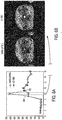
- FIGS. 6A and 6B show how the soft-gating described herein compares to the hard gating approach
- the hard gating data 602 are indicated by squares, and can be provided by a sensor attached to a band around the patient's abdomen to detect maximum exhalation and inhalation, for example.
- the hard gating data 602 show a local maximum CA concentration at time 10.
- the XD VIBE data 604 reflecting both time and motion state dimensions is indicated by asterisks.
- time 8 in FIG. 6A correspond to the arterial phase-the XD VIBE data 604 include a global maximum CA concentration due to inflow-outflow behavior, which is not detected by hard gating data 602.
- FIG. 6B shows the reconstructed images for the same slice based on hard gating (left) and XD VIBE with time and motion state (right).
- the XD VIBE image has greater contrast and less noise.
- a DCE-MRI scan of the liver was performed in free breathing on a clinical 3T scanner (MAGNETOM Skyra, Siemens Healthcare, Erlangen, Germany).
- Reconstruction was performed using a C++ prototype for the case of 6 motion-states and for a gating acceptance of 40%, respectively.
- FIGS. 5A-5D show the navigation signal used during this experiment.
- FIG. 5A shows the separate navigation signal Si,r from one of the coils 12, 14, 18 during a navigation scan performed between fat preparation and imaging scans.
- the navigation signal data are to be used to label the k-space data.
- the coils 12, 14 and 18 are at different locations in the head-to-foot (Z) direction.
- the horizontal axis in FIGs. 5A-5D represents time.
- Each column in FIG. 5A represents 1 image.
- the X-axis is the time coordinate for the image at different times.
- the acquired navigation signal Si,r(z) ( FIG. 5A ) corresponds to projections in head-feet direction with the same excitation volume as the imaging scans.
- FIG. 5A there is a dark band 501 above a white band 503.
- the white band 503 is the signal representing liver motion state, and the dark band 501 above it represents the diaphragm motion state, as the liver moves up and down.
- the navigation data shows that the liver is moving down significantly and comes back up, corresponding to movement of the diaphragm.
- Fig. 5B shows the phase of the navigation signal Si,r of FIG. 5A as a function of time for a selected coil element 12, 14 or 18.
- the signal shows variation due to breathing motion, and the method will align the phase with the breathing motion.
- the signal for the selected coil element is binned into 16 time points, assigned motion indices for 6 motion-states as well as clustering according to motion index for each time point, separately.
- FIG. 5C shows the motion state of the navigation signal Si,r.
- the course of the motion state shows clear periodic motion that may be attributed to motion of the liver and which is most extreme during contrast injection at the 3rd time point.
- FIG. 5D shows the clustering of the navigation signal for 6 motion-states as well as a sorting according to motion-states for each time point.
- FIG. 7A shows the first 6 time points are shown in respective columns 1 to 6 for a slice close to the liver dome using a hard-gated reconstruction with a gating tolerance of 40%.
- FIG. 7B shows a motion-resolved reconstruction with 6 motion-states ranging from inhalation to exhalation. For brevity, only the even-numbered motion states are shown, but the odd-numbered motion states can be reconstructed in the same manner.
- the hard-gated reconstruction shows good results at time points with moderate motion and signal change. However, at time point 3 with contrast agent arrival and stronger breathing motion, the motion-resolved reconstruction ( FIG.
- FIG. 7B provides better image quality than the hard gated reconstruction ( FIG. 7A ) for the exhaled state.
- the motion-resolved reconstruction ( FIG. 7B ) also shows fewer vessels at later time points which indicates less blurring in the through-plane direction.
- liver DCE for Cartesian acquisitions when imaging scans are clustered according to motion-states.
- Reconstruction times and image volumes scale at least linear in the motion-states.
- Other embodiments include a variable number of motion-states or a combination with hard-gating.
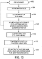
- FIG. 10 is a flow chart of an exemplary XD VIBE method as described above.
- step 1002 a loop including steps 1004 to 1008 is performed for each image.
- a fat suppression technique such as a fat preparation pulse is performed.
- the fat suppression method can include difference in resonance frequency with water by means of frequency selective pulses, phase contrast techniques, short T1 relaxation time by means of inversion recovery sequences (STIR technique), a so-called Dixon method, or a hybrid technique combining two or more of these fat suppression techniques such as SPIR (spectral presaturation with inversion recovery).
- the navigation signal data for the image are acquired
- the navigation signal has a frequency band corresponding to motion of the patient's diaphragm.
- the navigation signal corresponds to a frequency band corresponding to motion of the patient's heart.
- the k-space data for the image are sampled using a Cartesian trajectory.
- the k-space data are acquired in ascending order according to a Gaussian distribution.
- the k-space data are clustered using a clustering method, such as a k-means algorithm.
- the motion state for each of the k-space data are computed based on the clustering.
- Each of the k-space data is labeled with its corresponding motion state.
- At step 1014 at least one image is reconstructed using k-space data corresponding to at least two motions states corresponding to the same point in time. In some embodiments, at least one image is reconstructed using k-space data corresponding to all of the motions states corresponding to the same point in time.
- the system reconstructs images using data from all motion states at multiple time points.
- the system uses a first number of motion states for reconstruction at certain time points, and uses a second number of motion states for reconstruction at other time points, where the first number and second number are different from each other.
- the system only performs full motion state resolution for certain time points, and performs resolution for a single motion state at the remaining time points.
- a first image is reconstructed from k-space data corresponding to a first number of motion states acquired at the first time
- a second image is reconstructed from k-space data corresponding to a second number of motion states acquired at the second time, where the second number is different from the first number
- the system can perform full motion state resolution every 10 seconds, and the image is resolved for a single motion state at the remaining time points.
- FIG. 8 is a schematic diagram showing the data used during image reconstruction in some embodiments of the XD Hybrid method.
- the gray boxes 801, 804, 807 indicate data from different points in time corresponding to a first motion state.
- the second row of boxes 804, 805, 806 in FIG. 8 corresponds to a predetermined critical time (e.g., when the CA arrives at the liver) when the CA concentration is expected to be greatest, based on empirical knowledge of CA inflow/outflow.
- extra data indicated by black boxes
- 806 corresponding to additional motion states are used to reconstruct the image, for better image quality.
- the images for the first motion state (gray boxes 801, 807 can be processed using only the data from a single image.
- the final image for a critical time and desired motion state is obtained from: min X tUm ⁇ y ⁇ AX tUm ⁇ + ⁇ t ⁇ ⁇ t X t ⁇ + ⁇ m ⁇ ⁇ m X m ⁇ , where:
- FIG. 8 shows an example in which only three points in time and three motion states are considered, any number of points in time and any number of motion states can be used.
- FIG. 9 is a more general schematic diagram, in which an XD Hybrid embodiment can use any number of points in time, and any number of motion states to reconstruct an image at a critical point in time for a desired motion state.
- FIG. 11 is a flow chart of an exemplary XD Hybrid method according to some embodiments.
- the 5D k-space data are acquired and labeled as described above with respect to FIG. 10 .
- step 1104 a loop including steps 1106-1110 is repeated for each image.
- the image is reconstructed using k-space data corresponding to a single motion state at multiple points in time, to increase performance.
- the image is reconstructed using k-space data corresponding to all of the motion states acquired at that same point in time, to increase image quality.
- the XD Hybrid method provided improved image quality at critical points in time, and improved image reconstruction time for images acquired at non-critical points in time.
- the methods and system described herein may be at least partially embodied in the form of computer-implemented processes and apparatus for practicing those processes.
- the disclosed methods may also be at least partially embodied in the form of tangible, non-transitory machine readable storage media encoded with computer program code.
- the media may include, for example, RAMs, ROMs, CD-ROMs, DVD-ROMs, BD-ROMs, hard disk drives, flash memories, or any other non-transitory machine-readable storage medium, wherein, when the computer program code is loaded into and executed by a computer, the computer becomes an apparatus for practicing the method.
- the methods may also be at least partially embodied in the form of a computer into which computer program code is loaded and/or executed, such that, the computer becomes a special purpose computer for practicing the methods.
- the computer program code segments configure the processor to create specific logic circuits.
- the methods may alternatively be at least partially embodied in a digital signal processor formed of application specific integrated circuits for performing the methods.
Landscapes
- Physics & Mathematics (AREA)
- Health & Medical Sciences (AREA)
- Engineering & Computer Science (AREA)
- Nuclear Medicine, Radiotherapy & Molecular Imaging (AREA)
- Life Sciences & Earth Sciences (AREA)
- General Physics & Mathematics (AREA)
- General Health & Medical Sciences (AREA)
- Radiology & Medical Imaging (AREA)
- High Energy & Nuclear Physics (AREA)
- Signal Processing (AREA)
- Condensed Matter Physics & Semiconductors (AREA)
- Biophysics (AREA)
- Medical Informatics (AREA)
- Biomedical Technology (AREA)
- Heart & Thoracic Surgery (AREA)
- Molecular Biology (AREA)
- Surgery (AREA)
- Animal Behavior & Ethology (AREA)
- Public Health (AREA)
- Veterinary Medicine (AREA)
- Pathology (AREA)
- Theoretical Computer Science (AREA)
- Computer Vision & Pattern Recognition (AREA)
- Physiology (AREA)
- Artificial Intelligence (AREA)
- Vascular Medicine (AREA)
- Power Engineering (AREA)
- Psychiatry (AREA)
- Gastroenterology & Hepatology (AREA)
- Pulmonology (AREA)
- Cardiology (AREA)
- Quality & Reliability (AREA)
- Endocrinology (AREA)
- Magnetic Resonance Imaging Apparatus (AREA)
Abstract
Description
- This disclosure relates generally to methods, systems, and apparatuses for Magnetic Resonance Imaging (MRI) reconstruction.
- Imaging inverse problems such as reconstruction, deblurring, super-resolution, inpainting, or denoising can be solved by assuming the target image is sparse in the wavelet domain. Orthogonal wavelet transforms are not shift-invariant; image features are processed differently depending on their position with respect to the wavelet grid, and this can result in blocking artifacts.
- Techniques to solve the proximal operation performed during reconstruction have been developed, such as the utilization of an undecimated redundant wavelet transforms in conjunction with a nested inner algorithm inside the main solver (e.g. Chambolle-Pock or Dykstra inside FISTA).
- Dynamic contrast-enhanced (DCE) MRI involves injection of a contrast agent (CA) into the patient and observing the dynamic intake of the CA into tissue at several different points in time using MRI. Image reconstruction methods apply multiple shifted wavelet transforms at each iteration, which incurs an extra computational cost of at least a factor of 2 per image dimension. Additionally, exact undecimated wavelet methods also store the wavelet coefficients of the image, which are larger than the image by a factor of two in every dimension. This becomes very large with large-dimension use-cases such as dynamic volumetric reconstruction (3D+T), motion-compensated imaging, multi-contrast imaging including flow or diffusion, etc.
- In some embodiments, a method comprises acquiring navigation signal data during navigation scans at each of a plurality of points in time. A plurality of magnetic resonance imaging (MRI) k-space data corresponding to an imaged object are acquired at the plurality of points in time using Cartesian sampling, the k-space data including at least two spatial dimensions, time and an assigned motion state. The respective motion state for each of the k-space data are computed based on navigation data. At least one image is reconstructed from the plurality MRI k-space data using k-space data corresponding to at least two motion states and the same point in time to reconstruct the at least one image.
- In some embodiments, a magnetic resonance (MR) imaging device has a plurality of coils, and is configured to collect data representing an MR image from an object. A processor has a storage device for storing frequency components of the data acquired using a Cartesian acquisition strategy during acquisition of the frequency components, the processor programmed for acquiring navigation signal data during navigation scans at each of a plurality of points in time. A plurality of magnetic resonance imaging (MRI) k-space data corresponding to an imaged object are acquired at the plurality of points in time using Cartesian sampling, the k-space data including at least two spatial dimensions, a time, and a motion state. The respective motion state for each of the k-space data are computed based on navigation data. At least one image is reconstructed from the plurality MRI k-space data using k-space data corresponding to at least two motion states and the same point in time to reconstruct the at least one image.
- In some embodiments, a non-transitory machine-readable storage medium encoded with computer program code, wherein when a processor executes the computer program code, the processor performs a method comprising acquiring navigation signal data during navigation scans at each of a plurality of points in time. A plurality of magnetic resonance imaging (MRI) k-space data corresponding to an imaged object are acquired at the plurality of points in time using Cartesian sampling, the k-space data including at least two spatial dimensions, a time. The respective motion state for each of the k-space data are computed based on navigation data. At least one image is reconstructed from the plurality MRI k-space data using k-space data corresponding to at least two motion states and the same point in time to reconstruct the at least one image.
-
-
FIG. 1 shows a system for ordering acquisition of frequency domain components representing magnetic resonance (MR) image data for storage in a k-space storage array, as used by some embodiments. -
FIG. 2 is a diagram of a navigation signal spanning three amplitude ranges that correspond to three respective motion states of a subject (e.g., a patient). -
FIG. 3 is a schematic diagram showing a plurality of acquired image data which include two extra dimensions for time and motion (e.g., respiratory motion) state. -
FIG. 4 is a schematic diagram showing the bands of wavelet coefficients for the MR k-space data. -
FIG. 5A shows the magnitude of the navigation signal over time. -
FIG. 5B shows the phase of the navigation signal ofFIG. 5A over time. -
FIG. 5C shows the assigned motion states of the navigation signal ofFIG. 5A over time. -
FIG. 5D shows the acquired navigation signal ofFIG. 5A clustered according to the assigned motion states. -
FIG. 6A shows a comparison between the hard gating signal (squares) and the navigation signal (asterisks) over time. -
FIG. 6B shows the images reconstructed from MR data using the hard gating signal and the 5D image data with extra time and motion state dimensions described herein. -
FIG. 7A shows images reconstructed using the hard gating signal ofFIG. 6A over six points in time. -
FIG. 7B shows images reconstructed using the navigation signal ofFIG. 6A over the same six points in time. -
FIG. 8 is a schematic diagram of an XD Hybrid embodiment using data corresponding to extra motion states at critical points in time, and using data corresponding to a single motion state at other points in time. -
FIG. 9 is a schematic diagram of a generalized method using the XD Hybrid technique ofFIG. 8 . -
FIG. 10 is a flow chart of an exemplary MRI method according to some embodiments. -
FIG. 11 is a flow chart of an XD Hybrid method according to some embodiments. - This description of the exemplary embodiments is intended to be read in connection with the accompanying drawings, which are to be considered part of the entire written description. In the description, relative terms such as "lower," "upper," "horizontal," "vertical,", "above," "below," "up," "down," "top" and "bottom" as well as derivative thereof (e.g., "horizontally," "downwardly," "upwardly," etc.) should be construed to refer to the orientation as then described or as shown in the drawing under discussion..
- This disclosure describes several embodiments directed at methods, systems, and apparatuses Magnetic Resonance Imaging (MRI) reconstruction using wavelet regularization. The techniques described herein may be applied to many if not all compressed sensing (CS) use-cases to provide an overall performance improvement without sacrificing image quality. U.S. Patent Application Publication No.
US2016/0247263 by Mailhe et al . describes use of wavelets for regularization and reconstructing magnetic resonance images, and is incorporated by reference herein in its entirety. U.S. Patent Application Publication No.US2016/0146915 by Mailhe et al . describes a compressed sensing process for reconstructing magnetic resonance images, and is incorporated by reference herein in its entirety. - Some embodiments described herein use a Cartesian data acquisition method with a gating signal that is separate from spatial image data and time (perfusion state). The gating signal is representative of the motion state. Using Cartesian based acquisition simplifies computations and speeds up image processing. Some embodiments use the gating signal to resolve images collected in all motion states MRI scanning. Other embodiments use a hybrid approach, in which the gating signal is used to resolve images collected in all motion states at selected times (e.g., at certain perfusion states), and to only resolve images collected in a single or multiple selected motion states at all other times.
-
FIG. 1 shows asystem 100 for ordering acquisition of frequency domain components representing Magnetic Resonance (MR) image data for storage in a k-space storage array, as used by some embodiments of the present invention. Insystem 100,magnetic coils 12 create a static base magnetic field in the body ofpatient 11 to be imaged and positioned on a table. Within the magnet system aregradient coils 14 for producing position dependent magnetic field gradients superimposed on the static magnetic field. Gradient coils 14, in response to gradient signals supplied thereto by a gradient and shimcoil control module 16, produce position dependent and shimmed magnetic field gradients in three orthogonal directions and generates magnetic field pulse sequences. The shimmed gradients compensate for inhomogeneity and variability in an MR imaging device magnetic field resulting from patient anatomical variation and other sources. The magnetic field gradients include a slice-selection gradient magnetic field, a phase-encoding gradient magnetic field and a readout gradient magnetic field that are applied topatient 11. - Further RF (radio frequency)
module 20 provides RF pulse signals toRF coil 18, which in response produces magnetic field pulses which rotate the spins of the protons in the imaged body of the patient 11 by ninety degrees or by one hundred and eighty degrees for so-called "spin echo" imaging, or by angles less than or equal to 90 degrees for so-called "gradient echo" imaging. Gradient and shimcoil control module 16 in conjunction withRF module 20, as directed bycentral control unit 26, control slice-selection, phase-encoding, readout gradient magnetic fields, radio frequency transmission, and magnetic resonance signal detection, to acquire magnetic resonance signals representing planar slices ofpatient 11. - In response to applied RF pulse signals, the
RF coil 18 receives MR signals, i.e., signals from the excited protons within the body as they return to an equilibrium position established by the static and gradient magnetic fields. The MR signals are detected and processed by a detector withinRF module 20 and k-spacecomponent processor unit 34 to provide an MR dataset to an image data processor for processing into an image. In some embodiments, the image data processor is located incentral control unit 26. However, in other embodiments such as the one depicted inFIG. 1 , the image data processor is located in aseparate unit 27. ECGsynchronization signal generator 30 provides ECG signals used for pulse sequence and imaging synchronization. A two or three dimensional k-space storage array of individual data elements in k-spacecomponent processor unit 34 stores corresponding individual frequency components comprising an MR dataset. The k-space array of individual data elements has a designated center and individual data elements individually have a radius to the designated center. - A magnetic field generator (comprising coils 12, 14 and 18) generates a magnetic field for use in acquiring multiple individual frequency components corresponding to individual data elements in the storage array. The individual frequency components are successively acquired using a Cartesian acquisition strategy as the multiple individual frequency components are sequentially acquired during acquisition of an MR dataset representing an MR image. A storage processor in the k-space
component processor unit 34 stores individual frequency components acquired using the magnetic field in corresponding individual data elements in the array. The row and/or column of corresponding individual data elements alternately increases and decreases as multiple sequential individual frequency components are acquired. The magnetic field acquires individual frequency components in an order corresponding to a sequence of substantially adjacent individual data elements in the array and magnetic field gradient change between successively acquired frequency components is substantially minimized. -
Central control unit 26 uses information stored in an internal database to process the detected MR signals in a coordinated manner to generate high quality images of a selected slice(s) of the body (e.g., using the image data processor) and adjusts other parameters ofsystem 100. The stored information comprises predetermined pulse sequence and magnetic field gradient and strength data as well as data indicating timing, orientation and spatial volume of gradient magnetic fields to be applied in imaging. Generated images are presented ondisplay 40 of the operator interface.Computer 28 of the operator interface includes a graphical user interface (GUI) enabling user interaction withcentral control unit 26 and enables user modification of magnetic resonance imaging signals in substantially real time.Display processor 37 processes the magnetic resonance signals to provide image representative data for display ondisplay 40, for example. - Many challenges in medical imaging such as reconstruction, denoising or super-resolution can be modeled mathematically as ill-posed linear inverse problems:

where the goal is to reconstruct an unknown signal y from partially incomplete data x that is corrupted by measurement noise n. The matrix A models the measurement system. In case of parallel MRI it is often modeled as A = FS with F representing the (partial) Fourier transform and S containing the coil sensitivities. Because the system is underdetermined, there exist infinitely many solutions to it and additional constraints to the solution are imposed. A standard approach to the estimator of Equation (1) is as follows:
where
- In some embodiments the solution is sparse with respect to a given basis, meaning having only few non-zero coefficients in that basis. Compressed sensing is a signal processing technique, in which the sparsity of a signal is exploited to recover it from far fewer samples than required by the Shannon-Nyquist sampling theorem. A popular approach in compressed sensing is a wavelet based framework and promoting sparsity in a given wavelet basis such as Haar. However, having the measure of non-zeroes ||·||0 as a regularizer is NP-hard. Thus, in case of a wavelet based compressed sensing, the regularizer has often the form of || Wx ||1 and promotes sparsity with respect to the ℓ1-norm that is a convex approximation to the ℓ0 pseudo-norm. Here W represents a wavelet transform. In general, W can be any linear operator depending on the underlying problem. For example, for MRI reconstruction, some embodiments use an undecimated wavelet transform due to its translation invariance. However, the choice of algorithms to solve the optimization problem depends on the underlying regularizer. An efficient algorithm to solve Equation (1) is the iterative shrinkage/thresholding algorithm (ISTA), which is a special case of so called forward-backward splitting algorithms. A forward-backward splitting algorithm splits the problem into functions

- Given a function g(x), the proximal operator is the solution of the minimization problem:

- Note that Equation (3) is essentially a denoising problem. Many functions have closed form solutions of their proximal operator. Of special interest in this work is the proximal operator of the ℓ1-norm, which yields the soft-shrinkage operator defined as the point-wise shrinkage function:

- An efficient algorithm to solve Equation (2) that utilizes proximal operations is the iterative shrinkage/ thresholding algorithm called ISTA and its accelerated version called Fast-ISTA (FISTA). The algorithm below is derived from the perspective of the majorization-minimization (MM) prescription. MM minimizes a convex surrogate to a function rather than the function itself. Consider a function Q(Θ|Θ m ) of Θ that depends on a fixed parameter Θ m . Given a function f(Θ), Q(Θ|Θ m ) is said to majorize f at the point Θ m if


- The minimizer of the function Q can be shown to descent the function f such that

- The minimization problem shown in Equation (2) can be split into two functions


- Q satisfies the conditions in Equations (5) and (6) for a given xk and with λ ∈ (0,1/L], where L is a Lipschitz constant of ∇f and Φ(x) ≥ 0∀x.
- Iteratively minimizing Q yields the IST algorithm:

- Equation (9) admits the form of Equation (3) with u = xk - ∇f(xk ) and thus, the IST algorithm can also be written as:

- If Φ = 0,
Equation 10 comprises minimizing a smooth convex function and, thus, reduces to the simple gradient method. If Φ is the ℓ1-norm, prox λΦ yields the closed form solution given inEquation 4. - ISTA can be further adapted with an accelerated scheme referred to as Fast ISTA or simply FISTA. FISTA includes an extrapolating step in the algorithm:

where the initializers are Γ1 = 1 and y = x0. Additionally, FISTA can be further generalized in a form referred to as relaxed ISTA where the extrapolation step is expressed as:
- The techniques discussed above apply if Φ(·) is separable. However, in a wavelet based framework, one often encounters Φ(x) = ||Wx||1. If W is an orthogonal transform, Φ(·) is separable and the above techniques can be applied for finding sparse solutions. In practical settings however, orthogonal wavelet transforms lack shift-invariance. In MRI reconstruction this yields to more noise and block artifacts in the reconstructed image compared to undecimated wavelet transforms. On the other hand, undecimated or redundant transforms have higher memory consumption because of the missing decimation step.
- In clinical practice, abdominal dynamic contrast-enhanced (DCE) MRI is performed using multiple breath-hold acquisitions over a period of minutes. In particular iterative reconstruction techniques can provide continuous free-breathing acquisitions with high spatio-temporal resolution into clinical range. This provides patient comfort and robustness, and also aims at quantitative imaging. Some embodiments disclosed herein resolve motion-states as an additional dimension in the image reconstruction. Some embodiments use a Cartesian acquisition strategy with a motion-state detection based on additional navigation scans. The navigation scans are aligned with fat preparation pulses (e.g., frequency selective pulses) and come at practically no time cost. Motion-states are determined by clustering the imaging scans based on those navigation signals, so that imaging scans within a given cluster have navigation signal values closer to each other than to the navigation signal values of imaging scans in other clusters.
- A 3D Cartesian spoiled Volume-Interpolated Breath-hold Examination (VIBE) gradient echo (GRE) sequence supporting spectral fat suppression can be extended to support variable-density sampling of the phase-encoding plane as well as the acquisition of a navigation signal as follows:
- Some embodiments are suitable for DCE MRI in liver or other tissue. When imaging the liver, the liver is moving during air inhalation and exhalation, because image acquisition is slow (relative to the motion). Motions of the diaphragm are reflected onto the liver during this slow scanning. DCE MRI makes a series of images of the tissue. The series of images captures physical motions and also image contrast changes (due to CA movement into and out from the liver). CS shortens acquisition time per image. CS can allow the patient to breathe freely during acquisition of the sequence of images, because there is little reduction in image quality due to very small motion during the acquisition of a single one of the images. With CS, one can continuously acquire data, and retrospectively exclude data outside of the observation window.
- In some embodiments, data acquisition captures data in five dimensions. In addition to three spatial dimensions, time provides a fourth dimension. Because general CA inflow behavior is known empirically, the key points in time for dynamic imaging (relative to CA injection time) can be predicted, and the time is representative of perfusion state. A fifth dimension corresponding to motion states is captured. A clinical application is perfusion where there is CA flowing in, and the intensity of the CA within the body changes. The exemplary methods resolve motion as well as inflow (time domain). For DCE MRI, the time at which the CA is expected to reach tissue (such as the liver) is known empirically, and is an additional significant independent variable for the image resolution.
- In some embodiments, given a self-navigation signal in the general form of a sinusoidal curve, the system assigns certain amplitude values of the self-navigation signal to certain motion states, such as inhale and exhale. A simple system can use two motion states for inhalation and exhalation. In other embodiments, additional motion states are used, corresponding to additional positions between maximum inhalation and maximum inhalation.
-
FIG. 2 shows an example of agating signal 202, which is representative of breathing motion. A motion signal from theRF coil - The total amplitude range of the
signal 202 can be divided into any desired number of ranges, each corresponding to a respective motion state. In some embodiments, each motion state corresponds to a respective cluster of k-space data. For example, inFIG. 2 , the amplitude range of thegating signal 202 is divided into threeranges Range 204 corresponds to maximum inhalation.Range 208 corresponds to maximum exhalation.Range 206 corresponds to intermediate states. This is only one example. Other embodiments can divide the total amplitude range of thesignal 202 into 2, 4, 6 or 8 ranges, or any other number to provide a desired precision for the respiratory state data. - For multiple time points, the sampling is generated in ascending order according to a Gaussian distribution, guaranteeing that at each time point the expectation value for acquiring a phase-encoding step differs from its actual acquisition number by at most one. The set of phase-encoding steps is assigned to the echo trains following the fat preparation pulses. For navigation, an additional GRE module is played out after each fat suppression pulse differing from the imaging scans only in the readout. The latter is put in head-feet direction.
- The 3D Cartesian data are supplemented with the time dimension and a fifth dimension defining a motion state.

- For DCE, the time dimension identifies the contrast agent (CA) uptake state. For liver images, the relevant motion state can define diaphragm position. For example,
FIG. 3 schematically shows the image data for a given slice (spatial region) is acquired and associated with motion state data from one of three different respiratory states, at three different points in time. Although the example ofFIG. 3 has the same number of time points as motion states, any number of time points can be used, independent of the number of motion states. -
FIG 4 is a schematic diagram showing the Wavelet coefficients, representing the signals in the wavelet domain. The blocks inFIG. 4 represent "bands" in the wavelet domain. The upper left corner band represent the low frequency component in the time direction and low frequency component in the motion state direction. The upper right corner band represents the low frequency component in the time direction and high frequency component in the motion state direction. No matter how many time points or motion states are included in the k-space data, after a wavelet transform along the two dimensions, the wavelet coefficients can be categorized into these four bands. - Regularization applied on all spatial, DCE and motion-state directions, with different regularization levels, using.

- The extra respiratory motion-state dimension is used to disentangle dynamic contrast enhancement and respiratory motions. Additional data are acquired for a small liver dome region showing how the diaphragm is moving to directly image respiratory motion.
FIGS. 5A-5D show a sample of the navigation signals from which the motion states are obtained. - Some embodiments acquire the navigating signal together with k-space data, compute motion states, cluster the k-space data according to motion state of the navigation signal. and label each acquired k-space data with the corresponding motion state, and then decide how to use this data. In the case of acquired data acquired outside of the relevant window, the system does not discard the data, but suppresses their relevance.
- The method concatenates image data into large 4D or 5D cube. The 4D cube includes 2D spatial data, plus time and motion state. The 5D cube includes 3D spatial data, plus time and motion state. Regularization is performed on the 4D or 5D cube. During reconstruction, the images may be adjusted to try to make images corresponding to neighboring motion states look similar to each other. Each motion state should be a faithful representation of its data, while at the same time, adjacent motion states should be similar to each other. This is done by applying wavelet transform over the entire 4D or 5D cube of data. It's 5D, but sometimes it is reconstructed as 2D or 3D spatial, plus time, plus motion state.
- Using a generalized k-means algorithm, the navigation signal is clustered into N motion-states by minimizing

- with Si,r being the ith navigation scan at the rth time point. C is a motion state, i is a scan index, r is a time index, m is a mean motion state, N is a number of motion states, R is the number of points in time, Si,r is a value of the navigation signal data for an ith navigation scan at an rth point in time. Alpha (α) is a tuned parameter that regulates whether centroids within a time-point are determined for each time point separately (α=0) or whether the same centroids are used for all time-points (α=infinity). In some embodiments, α is set to 0.1 for reconstruction.
FIG. 5A shows an example of a navigation scan signal. The optimization is performed for eachcoil element 
- with W being a redundant wavelet transformation (e.g., Haar or Debauchies), λ the regularization strength and F consisting of multiplication with coil-sensitivities, Fourier transformation and masking.
- In addition a reconstruction using a fixed gating acceptance for a single motion-state (referred to as hard-gating) provides a basis for comparison with soft-gating as described herein. In some embodiments, the system displays a second image reconstructed using the fixed gating signal adjacent to at least one image reconstructed using the motion state data, such as shown in
FIGS. 6B ,7A and 7B . The optimization problem above is then modified to finding the best subset of given size at each time point. -
FIGS. 6A and 6B show how the soft-gating described herein compares to the hard gating approach InFIG. 6A , thehard gating data 602 are indicated by squares, and can be provided by a sensor attached to a band around the patient's abdomen to detect maximum exhalation and inhalation, for example. Thehard gating data 602 show a local maximum CA concentration attime 10. TheXD VIBE data 604 reflecting both time and motion state dimensions is indicated by asterisks. At time 8 inFIG. 6A -corresponding to the arterial phase-theXD VIBE data 604 include a global maximum CA concentration due to inflow-outflow behavior, which is not detected byhard gating data 602. -
FIG. 6B shows the reconstructed images for the same slice based on hard gating (left) and XD VIBE with time and motion state (right). The XD VIBE image has greater contrast and less noise. - A DCE-MRI scan of the liver was performed in free breathing on a clinical 3T scanner (MAGNETOM Skyra, Siemens Healthcare, Erlangen, Germany). Parameters of the VIBE acquisition included FoV = 380x345x192mm3, image matrix = 320x290x64, TE/TR= 1.8/3.76ms, flip angle = 10°, 6-fold acceleration in the phase-encoding with the probability distribution of the variable sampling at the borders dropping to 1/5 of its central value as well as 16 time points with a temporal resolution of 11,57s each. Reconstruction was performed using a C++ prototype for the case of 6 motion-states and for a gating acceptance of 40%, respectively.
FIGS. 5A-5D show the navigation signal used during this experiment. -
FIG. 5A shows the separate navigation signal Si,r from one of thecoils coils FIGs. 5A-5D represents time. Each column inFIG. 5A represents 1 image. The X-axis is the time coordinate for the image at different times. - The acquired navigation signal Si,r(z) (
FIG. 5A ) corresponds to projections in head-feet direction with the same excitation volume as the imaging scans. InFIG. 5A , there is adark band 501 above awhite band 503. Thewhite band 503 is the signal representing liver motion state, and thedark band 501 above it represents the diaphragm motion state, as the liver moves up and down. In thethird column 505, the navigation data shows that the liver is moving down significantly and comes back up, corresponding to movement of the diaphragm. -
Fig. 5B shows the phase of the navigation signal Si,r ofFIG. 5A as a function of time for a selectedcoil element - The signal for the selected coil element is binned into 16 time points, assigned motion indices for 6 motion-states as well as clustering according to motion index for each time point, separately.
FIG. 5C shows the motion state of the navigation signal Si,r. The course of the motion state shows clear periodic motion that may be attributed to motion of the liver and which is most extreme during contrast injection at the 3rd time point. -
FIG. 5D shows the clustering of the navigation signal for 6 motion-states as well as a sorting according to motion-states for each time point. - Reconstructed images close to the liver dome are shown in
Fig. 7A and 7B. FIG. 7A shows the first 6 time points are shown in respective columns 1 to 6 for a slice close to the liver dome using a hard-gated reconstruction with a gating tolerance of 40%.FIG. 7B shows a motion-resolved reconstruction with 6 motion-states ranging from inhalation to exhalation. For brevity, only the even-numbered motion states are shown, but the odd-numbered motion states can be reconstructed in the same manner. The hard-gated reconstruction (FIG. 7A ) shows good results at time points with moderate motion and signal change. However, at time point 3 with contrast agent arrival and stronger breathing motion, the motion-resolved reconstruction (FIG. 7B ) provides better image quality than the hard gated reconstruction (FIG. 7A ) for the exhaled state. The motion-resolved reconstruction (FIG. 7B ) also shows fewer vessels at later time points which indicates less blurring in the through-plane direction. - The techniques described herein permit free-breathing liver DCE for Cartesian acquisitions when imaging scans are clustered according to motion-states. Reconstruction times and image volumes scale at least linear in the motion-states. Other embodiments include a variable number of motion-states or a combination with hard-gating.
-
FIG. 10 is a flow chart of an exemplary XD VIBE method as described above. - At
step 1002, aloop including steps 1004 to 1008 is performed for each image. - At
step 1004, a fat suppression technique, such as a fat preparation pulse is performed. In various embodiments, the fat suppression method can include difference in resonance frequency with water by means of frequency selective pulses, phase contrast techniques, short T1 relaxation time by means of inversion recovery sequences (STIR technique), a so-called Dixon method, or a hybrid technique combining two or more of these fat suppression techniques such as SPIR (spectral presaturation with inversion recovery). - At
step 1006, the navigation signal data for the image are acquired In some embodiments, for imaging the liver, the navigation signal has a frequency band corresponding to motion of the patient's diaphragm. In other embodiments, the navigation signal corresponds to a frequency band corresponding to motion of the patient's heart. - At
step 1008, the k-space data for the image are sampled using a Cartesian trajectory. In some embodiments, the k-space data are acquired in ascending order according to a Gaussian distribution. - At
step 1010, the k-space data are clustered using a clustering method, such as a k-means algorithm. - At
step 1012, the motion state for each of the k-space data are computed based on the clustering. Each of the k-space data is labeled with its corresponding motion state. - At
step 1014, at least one image is reconstructed using k-space data corresponding to at least two motions states corresponding to the same point in time. In some embodiments, at least one image is reconstructed using k-space data corresponding to all of the motions states corresponding to the same point in time. - In some embodiments, as described above, the system reconstructs images using data from all motion states at multiple time points. In other embodiments, the system uses a first number of motion states for reconstruction at certain time points, and uses a second number of motion states for reconstruction at other time points, where the first number and second number are different from each other. For example, in some embodiments, referred to herein as the XD hybrid approach, the system only performs full motion state resolution for certain time points, and performs resolution for a single motion state at the remaining time points. For example, in some embodiments, a first image is reconstructed from k-space data corresponding to a first number of motion states acquired at the first time, and a second image is reconstructed from k-space data corresponding to a second number of motion states acquired at the second time, where the second number is different from the first number.
- For example, given a 2 min. scan, the system can perform full motion state resolution every 10 seconds, and the image is resolved for a single motion state at the remaining time points.
-
FIG. 8 is a schematic diagram showing the data used during image reconstruction in some embodiments of the XD Hybrid method. Thegray boxes boxes FIG. 8 corresponds to a predetermined critical time (e.g., when the CA arrives at the liver) when the CA concentration is expected to be greatest, based on empirical knowledge of CA inflow/outflow. At the predetermined time corresponding to the second row, extra data (indicated by black boxes) 805, 806 corresponding to additional motion states are used to reconstruct the image, for better image quality. For the remaining points in time, the images for the first motion state (gray boxes - According to this embodiment of an XD Hybrid method, the final image for a critical time and desired motion state is obtained from:

- Xt = 2D+t data at desired motion state
- Xm = 2D+motion states (+t) data at arterial phase(s)
- X t∪m = 2D data at arterial phase(s) and the desired motion state; the average of Xt and Xm at each iteration
- ψt = 3D wavelet transform. Thresholding scale along t.
- ψ m = 3D (or 4D) wavelet transform. Thresholding scale along motion (and t if multiple arterial phases)
- Although
FIG. 8 shows an example in which only three points in time and three motion states are considered, any number of points in time and any number of motion states can be used.FIG. 9 is a more general schematic diagram, in which an XD Hybrid embodiment can use any number of points in time, and any number of motion states to reconstruct an image at a critical point in time for a desired motion state. -
FIG. 11 is a flow chart of an exemplary XD Hybrid method according to some embodiments. - At
step 1102, the 5D k-space data are acquired and labeled as described above with respect toFIG. 10 . - At
step 1104, a loop including steps 1106-1110 is repeated for each image. - At
step 1106, a determination is made whether the image corresponds to a critical point in time. For example, in a perfusion study, a time corresponding to a maximum concentration of a CA in the tissue being imaged is a critical point in time. If the image corresponds to a critical time,step 1110 is executed. If the image does not correspond to a critical time,step 1110 is executed. - At
step 1108, the image is reconstructed using k-space data corresponding to a single motion state at multiple points in time, to increase performance. - At
step 1110, the image is reconstructed using k-space data corresponding to all of the motion states acquired at that same point in time, to increase image quality. - The XD Hybrid method provided improved image quality at critical points in time, and improved image reconstruction time for images acquired at non-critical points in time.
- The methods and system described herein may be at least partially embodied in the form of computer-implemented processes and apparatus for practicing those processes. The disclosed methods may also be at least partially embodied in the form of tangible, non-transitory machine readable storage media encoded with computer program code. The media may include, for example, RAMs, ROMs, CD-ROMs, DVD-ROMs, BD-ROMs, hard disk drives, flash memories, or any other non-transitory machine-readable storage medium, wherein, when the computer program code is loaded into and executed by a computer, the computer becomes an apparatus for practicing the method. The methods may also be at least partially embodied in the form of a computer into which computer program code is loaded and/or executed, such that, the computer becomes a special purpose computer for practicing the methods. When implemented on a general-purpose processor, the computer program code segments configure the processor to create specific logic circuits. The methods may alternatively be at least partially embodied in a digital signal processor formed of application specific integrated circuits for performing the methods.
- Although the subject matter has been described in terms of exemplary embodiments, it is not limited thereto. Rather, the appended claims should be construed broadly, to include other variants and embodiments, which may be made by those skilled in the art.
Claims (20)
- A method comprising:acquiring navigation data during navigation scans at each of a plurality of points in time;acquiring a plurality of magnetic resonance imaging (MRI) k-space data corresponding to an imaged object at the plurality of points in time using Cartesian sampling, the k-space data including at least two spatial dimensions, a time, and a motion state;computing the respective motion state for each of the k-space data based on the navigation data; andreconstructing at least one image from the plurality of MRI k-space data using k-space data corresponding to at least two motion states and the same point in time to reconstruct the at least one image.
- The method according to claim 1, further comprising clustering the k-space data according to navigation data using a k-means method.
- The method according to claim 2, wherein the clustering computes:

- The method according to any of the claims 1 to 3, wherein each of the plurality of points in time corresponds to a respective imaging scan and the step of acquiring navigation data is performed between a fat preparation pulse and a respective one of the imaging scans at a respective point in time.
- The method of claim 4, wherein each imaging scan has an excitation volume, and the navigation scans have a same excitation volume as the imaging scans.
- The method according to any of the claims 1 to 5, wherein the sampling is generated in ascending order according to a Gaussian distribution for the plurality of points in time.
- The method according to any of the claims 1 to 6, wherein the object is a patient, the navigation data is acquired from a coil near a diaphragm of the patient, and the at least one image is an image of a liver of the patient.
- The method according to any of the claims 1 to 7, further comprising providing a fixed gating signal for a single motion state, and displaying a second image reconstructed using the fixed gating signal adjacent to the at least one image.
- The method according to any of the claims 1 to 8, wherein:the plurality of points in time include a first time and a second time,the at least one image includes a first image reconstructed from k-space data corresponding to a first number of motion states acquired at the first time, the method further comprising:reconstructing a second image from k-space data corresponding to a a second number of motion states acquired at the second time, wherein the second number is different from the first number.
- The method according to claim 9, wherein the object is a liver of a patient, and a contrast agent flows into the liver at the first time.
- The method according to any of the claims 9 or 10, wherein the first image is reconstructed using k-space data corresponding to all of the motion states.
- A system comprising:a magnetic resonance (MR) imaging device having a plurality of coils, and configured to collect data representing an MR image from an object;a processor having a storage device for storing frequency components of the data acquired using a Cartesian acquisition strategy during acquisition of the frequency components, the processor programmed for:acquiring navigation data during navigation scans at each of a plurality of points in time;acquiring a plurality of magnetic resonance imaging (MRI) k-space data corresponding to an imaged object at the plurality of points in time using Cartesian sampling, the k-space data including at least two spatial dimensions, a time, and a motion state;computing the respective motion state for each of the k-space data, based on the navigation data; andreconstructing at least one image from the plurality MRI k-space data using k-space data corresponding to at least two motion states and the same point in time to reconstruct the at least one image.
- The system according to claim 12, further comprising clustering the k-space data according to the navigation data using a k-means method.
- The system according to any of the claims 12 and 13, wherein each of the plurality of points in time corresponds to a respective imaging scan and the processor is programmed to acquire navigation data between a fat preparation and a respective one of the imaging scans at a respective point in time.
- The system according to any of the claims 12 to 14, wherein the processor is programmed for displaying a second image reconstructed using the fixed gating signal adjacent to the at least one image.
- The system according to any of the claims 12 to 15, wherein the processor is programmed for:reconstructing the at least one image from k-space data corresponding to two or more motion states acquired at a first time, andreconstructing a second image from k-space data corresponding to a single motion state acquired at a second time.
- A non-transitory machine-readable storage medium encoded with computer program code, wherein when a processor executes the computer program code, the processor performs a method comprising the steps of:acquiring navigation data during navigation scans at each of a plurality of points in time;acquiring a plurality of magnetic resonance imaging (MRI) k-space data corresponding to an imaged object at the plurality of points in time using Cartesian sampling, the k-space data including at least two spatial dimensions, a time, and a motion state;computing the respective motion state for each of the k-space data based on the navigation data; andreconstructing at least one image from the plurality MRI k-space data using k-space data corresponding to at least two motion states and the same point in time to reconstruct the at least one image.
- The non-transitory machine-readable storage medium according to claim 17, wherein the processor is further programmed for providing a fixed gating signal for a single motion state, and displaying a second image reconstructed using the fixed gating signal adjacent to the at least one image.
- The non-transitory machine-readable storage medium according to any of the claims 17 or 18, wherein the processor is programmed for:reconstructing the at least one image from k-space data corresponding to two or more motion states acquired at a first time, andreconstructing a second image from k-space data corresponding to a single motion state acquired at a second time.
- The non-transitory machine-readable storage medium according to any of the claims 17 to 19, wherein the first image is reconstructed using k-space data corresponding to all of the motion states.
Applications Claiming Priority (2)
| Application Number | Priority Date | Filing Date | Title |
|---|---|---|---|
| US201562266511P | 2015-12-11 | 2015-12-11 | |
| US15/361,670 US10267883B2 (en) | 2015-12-11 | 2016-11-28 | System and method for motion resolved MRI |
Publications (2)
| Publication Number | Publication Date |
|---|---|
| EP3179264A2 true EP3179264A2 (en) | 2017-06-14 |
| EP3179264A3 EP3179264A3 (en) | 2017-08-02 |
Family
ID=57517748
Family Applications (1)
| Application Number | Title | Priority Date | Filing Date |
|---|---|---|---|
| EP16202468.1A Withdrawn EP3179264A3 (en) | 2015-12-11 | 2016-12-06 | System and method for motion resolved mri |
Country Status (4)
| Country | Link |
|---|---|
| US (1) | US10267883B2 (en) |
| EP (1) | EP3179264A3 (en) |
| KR (1) | KR101939642B1 (en) |
| CN (1) | CN106981051B (en) |
Cited By (4)
| Publication number | Priority date | Publication date | Assignee | Title |
|---|---|---|---|---|
| GB2572804A (en) * | 2018-04-12 | 2019-10-16 | Siemens Healthcare Ltd | Method of reconstructing magnetic resonance image data |
| CN110809721A (en) * | 2017-06-27 | 2020-02-18 | 皇家飞利浦有限公司 | Method and apparatus for determining a sports field from k-space data |
| CN116758182A (en) * | 2023-07-12 | 2023-09-15 | 山东第一医科大学附属省立医院(山东省立医院) | A fast liver imaging method and system based on motion sorting |
| TWI895207B (en) * | 2024-12-30 | 2025-08-21 | 國立中山大學 | Image processing method and device based on gradient difference accumulation nonnegative matrix factorization |
Families Citing this family (8)
| Publication number | Priority date | Publication date | Assignee | Title |
|---|---|---|---|---|
| US9858689B1 (en) * | 2016-09-15 | 2018-01-02 | Siemens Healthcare Gmbh | Fast and memory efficient redundant wavelet regularization with sequential cycle spinning |
| CN107507149A (en) * | 2017-08-31 | 2017-12-22 | 深圳市智图医疗技术有限责任公司 | A kind of noise-reduction method and device of Magnetic resonance imaging image |
| CN110321101B (en) * | 2018-03-30 | 2022-12-27 | 西门子(深圳)磁共振有限公司 | Instruction distribution method and device for magnetic resonance imaging sequence |
| US10950014B2 (en) * | 2019-03-01 | 2021-03-16 | Canon Medical Systems Corporation | Method and apparatus for adaptive compressed sensing (CS) to correct motion artifacts in magnetic resonance imaging (MRI) |
| US10884086B1 (en) * | 2019-07-29 | 2021-01-05 | GE Precision Healthcare LLC | Systems and methods for accelerated multi-contrast propeller |
| CN110988763B (en) * | 2019-11-05 | 2021-12-17 | 深圳先进技术研究院 | Magnetic resonance imaging method, magnetic resonance imaging device, server and storage medium |
| CN115880383A (en) * | 2021-09-30 | 2023-03-31 | 西门子(深圳)磁共振有限公司 | MR imaging method, device and computer readable storage medium |
| WO2024238469A2 (en) * | 2023-05-12 | 2024-11-21 | Ohio State Innovation Foundation | Systems and methods for cardiovascular magnetic resonance imaging |
Citations (2)
| Publication number | Priority date | Publication date | Assignee | Title |
|---|---|---|---|---|
| US20160146915A1 (en) | 2014-11-25 | 2016-05-26 | Siemens Aktiengesellschaft | Compressed Sensing Reconstruction for Multi-Slice and Multi-Slab Acquisitions |
| US20160247263A1 (en) | 2015-02-24 | 2016-08-25 | Siemens Aktiengesellschaft | Simultaneous Edge Enhancement And Non-Uniform Noise Removal Using Refined Adaptive Filtering |
Family Cites Families (22)
| Publication number | Priority date | Publication date | Assignee | Title |
|---|---|---|---|---|
| WO2007037951A2 (en) | 2005-09-22 | 2007-04-05 | Wisconsin Alumni Research Foundation | Reconstruction of motion encoded mr images involving a highly constrained backprojection |
| US7408347B2 (en) | 2005-09-22 | 2008-08-05 | Wisconsin Alumni Research Foundation | Highly constrained magnetic resonance spectroscopy image reconstruction method |
| CN101421637A (en) | 2006-04-13 | 2009-04-29 | 皇家飞利浦电子股份有限公司 | MRI of continuously moving objects involving motion compensation |
| JP2009254392A (en) * | 2008-04-11 | 2009-11-05 | Ge Medical Systems Global Technology Co Llc | Magnetic resonance imaging apparatus and image generating method |
| JP5171373B2 (en) * | 2008-04-24 | 2013-03-27 | ジーイー・メディカル・システムズ・グローバル・テクノロジー・カンパニー・エルエルシー | Magnetic resonance imaging apparatus and RF pulse applying method |
| EP2550541B1 (en) * | 2010-03-23 | 2017-07-12 | Max-Planck-Gesellschaft zur Förderung der Wissenschaften e.V. | Method and device for reconstructing a sequence of mr images using a regularized nonlinear inverse reconstruction process |
| US9121915B2 (en) | 2010-12-09 | 2015-09-01 | The Board Of Trustees Of The Leland Stanford Junior University | Multi-dimensional cardiac and respiratory imaging with MRI |
| WO2012085810A2 (en) * | 2010-12-22 | 2012-06-28 | Koninklijke Philips Electronics N.V. | Rapid parallel reconstruction for arbitrary k-space trajectories |
| US8306299B2 (en) * | 2011-03-25 | 2012-11-06 | Wisconsin Alumni Research Foundation | Method for reconstructing motion-compensated magnetic resonance images from non-Cartesian k-space data |
| US8975895B2 (en) * | 2012-01-13 | 2015-03-10 | The Board Of Trustees Of The University Of Illinois | Method for correcting motion-induced phase errors in magnetic resonance imaging |
| US9687172B2 (en) | 2012-01-24 | 2017-06-27 | National Institute of Health (NIH), The United States of America, U.S. Dept. of Health and Human Services (DHHS) | System for motion corrected MR diffusion imaging |
| GB201202565D0 (en) * | 2012-02-15 | 2012-03-28 | British American Tobacco Co | Packaging |
| JP6232043B2 (en) | 2012-03-19 | 2017-11-15 | コーニンクレッカ フィリップス エヌ ヴェKoninklijke Philips N.V. | Reconstruction of magnetic resonance images using detection of respiratory motion during sampling in the middle and periphery of the K-space region |
| DE102012206550A1 (en) * | 2012-04-20 | 2013-10-24 | Siemens Aktiengesellschaft | Method for acquiring a measurement data set of a breathing examination subject by means of magnetic resonance technique, magnetic resonance system, computer program and electronically readable data carriers |
| DE102012206555B4 (en) | 2012-04-20 | 2023-08-03 | Siemens Healthcare Gmbh | Method for acquiring a measurement data set of a breathing examination subject using magnetic resonance technology, magnetic resonance system, computer program and electronically readable data carrier |
| WO2014037868A1 (en) * | 2012-09-06 | 2014-03-13 | Koninklijke Philips N.V. | Magnetic resonance imaging system with navigator-based motion detection |
| CN105051564A (en) * | 2013-03-22 | 2015-11-11 | 皇家飞利浦有限公司 | Method for improved k-space sampling in compressed sensing MRI |
| US10288705B2 (en) * | 2013-10-08 | 2019-05-14 | Koninklijke Philips N.V. | Corrected multiple-slice magnetic resonance imaging |
| DE102014202358B4 (en) | 2014-02-10 | 2016-07-21 | Siemens Healthcare Gmbh | Optimization of rephasing gradient pulses in a simultaneous MR excitation of multiple layers |
| US9702956B2 (en) | 2014-03-25 | 2017-07-11 | Beth Israel Deaconess Medical Center, Inc. (Bidmc, Inc.) | MRI methods and apparatus for flexible visualization of any subset of an enlarged temporal window |
| RU2568929C1 (en) | 2014-04-30 | 2015-11-20 | Самсунг Электроникс Ко., Лтд. | Method and system for fast mri-images reconstruction from sub-sampled data |
| US10061004B2 (en) | 2014-12-17 | 2018-08-28 | Siemens Healthcare Gmbh | Memory efficiency of parallel magnetic resonance imaging reconstruction |
-
2016
- 2016-11-28 US US15/361,670 patent/US10267883B2/en not_active Expired - Fee Related
- 2016-12-06 EP EP16202468.1A patent/EP3179264A3/en not_active Withdrawn
- 2016-12-09 KR KR1020160167861A patent/KR101939642B1/en not_active Expired - Fee Related
- 2016-12-09 CN CN201611128449.1A patent/CN106981051B/en active Active
Patent Citations (2)
| Publication number | Priority date | Publication date | Assignee | Title |
|---|---|---|---|---|
| US20160146915A1 (en) | 2014-11-25 | 2016-05-26 | Siemens Aktiengesellschaft | Compressed Sensing Reconstruction for Multi-Slice and Multi-Slab Acquisitions |
| US20160247263A1 (en) | 2015-02-24 | 2016-08-25 | Siemens Aktiengesellschaft | Simultaneous Edge Enhancement And Non-Uniform Noise Removal Using Refined Adaptive Filtering |
Cited By (6)
| Publication number | Priority date | Publication date | Assignee | Title |
|---|---|---|---|---|
| CN110809721A (en) * | 2017-06-27 | 2020-02-18 | 皇家飞利浦有限公司 | Method and apparatus for determining a sports field from k-space data |
| GB2572804A (en) * | 2018-04-12 | 2019-10-16 | Siemens Healthcare Ltd | Method of reconstructing magnetic resonance image data |
| GB2572804B (en) * | 2018-04-12 | 2020-04-29 | Siemens Healthcare Ltd | Method of reconstructing magnetic resonance image data |
| US11360178B2 (en) | 2018-04-12 | 2022-06-14 | Siemens Healthcare Gmbh | Method and apparatus for reconstructing magnetic resonance image data |
| CN116758182A (en) * | 2023-07-12 | 2023-09-15 | 山东第一医科大学附属省立医院(山东省立医院) | A fast liver imaging method and system based on motion sorting |
| TWI895207B (en) * | 2024-12-30 | 2025-08-21 | 國立中山大學 | Image processing method and device based on gradient difference accumulation nonnegative matrix factorization |
Also Published As
| Publication number | Publication date |
|---|---|
| CN106981051A (en) | 2017-07-25 |
| KR20170074762A (en) | 2017-06-30 |
| US20170168129A1 (en) | 2017-06-15 |
| EP3179264A3 (en) | 2017-08-02 |
| KR101939642B1 (en) | 2019-01-17 |
| CN106981051B (en) | 2021-01-19 |
| US10267883B2 (en) | 2019-04-23 |
Similar Documents
| Publication | Publication Date | Title |
|---|---|---|
| US10267883B2 (en) | System and method for motion resolved MRI | |
| Godenschweger et al. | Motion correction in MRI of the brain | |
| Marami et al. | Temporal slice registration and robust diffusion-tensor reconstruction for improved fetal brain structural connectivity analysis | |
| US20200225307A1 (en) | System, method and computer-accessible medium for dynamic magnetic resonance imaging | |
| CN102078196B (en) | Method to detect breathing movement of an examination subject corresponding to signal data by magnetic resonance | |
| Küstner et al. | MR image reconstruction using a combination of compressed sensing and partial Fourier acquisition: ESPReSSo | |
| Kasten et al. | Data-driven MRSI spectral localization via low-rank component analysis | |
| US11327132B2 (en) | System and method for magnetic resonance imaging acceleration | |
| CN103597370A (en) | Spatially encoded phase-contrast MRI | |
| US12521033B2 (en) | Method and system for low-field MRI denoising with a deep complex-valued convolutional neural network | |
| Jhamb et al. | A review on image reconstruction through MRI k-space data | |
| US7495440B2 (en) | Q-space sampling method and diffusion spectrum imaging method employing the same | |
| Petrov et al. | Improving temporal resolution in fMRI using a 3D spiral acquisition and low rank plus sparse (L+ S) reconstruction | |
| US20240361412A1 (en) | Time-resolved image reconstruction using joint temporally local and global subspace modeling for mri | |
| Dai et al. | Distortion-free diffusion imaging using self-navigated Cartesian Echo-planar time resolved acquisition and joint magnitude and phase constrained reconstruction | |
| Zhong et al. | Understanding aliasing effects and their removal in SPEN MRI: A k‐space perspective | |
| Menchón-Lara et al. | An efficient multi-resolution reconstruction scheme with motion compensation for 5D free-breathing whole-heart MRI | |
| Zaid Alkilani | A deep learning model for susceptibility artifact correction in echo planar imaging | |
| Arefeen | Combining Computational Techniques with Physics for Applications in Accelerated MRI | |
| Li | Advanced Methods For Magnetic Resonance Image Reconstruction, Motion Artifact Correction And Quantitative Susceptibility Mapping | |
| Toner | Advancing Quantitative Abdominal MRI: Methods for Highly Accelerated T2 Mapping With Radial Turbo Spin-Echo Sequences | |
| Van Le | Improved Cardiac Perfusion and T1 Mapping in Magnetic Resonance Imaging | |
| Tang | Deep Learning Aided Accelerated MR Acquisition Reconstruction and Evaluation | |
| Topcu | Physics-constrained unsupervised deep learning for accelerated diffusion MRI | |
| Galea | Investigation of the effect of different functional MRI sequences on local homogeneity measures: implications for neuroimaging studies |
Legal Events
| Date | Code | Title | Description |
|---|---|---|---|
| PUAI | Public reference made under article 153(3) epc to a published international application that has entered the european phase |
Free format text: ORIGINAL CODE: 0009012 |
|
| STAA | Information on the status of an ep patent application or granted ep patent |
Free format text: STATUS: REQUEST FOR EXAMINATION WAS MADE |
|
| 17P | Request for examination filed |
Effective date: 20161206 |
|
| AK | Designated contracting states |
Kind code of ref document: A2 Designated state(s): AL AT BE BG CH CY CZ DE DK EE ES FI FR GB GR HR HU IE IS IT LI LT LU LV MC MK MT NL NO PL PT RO RS SE SI SK SM TR |
|
| AX | Request for extension of the european patent |
Extension state: BA ME |
|
| PUAL | Search report despatched |
Free format text: ORIGINAL CODE: 0009013 |
|
| AK | Designated contracting states |
Kind code of ref document: A3 Designated state(s): AL AT BE BG CH CY CZ DE DK EE ES FI FR GB GR HR HU IE IS IT LI LT LU LV MC MK MT NL NO PL PT RO RS SE SI SK SM TR |
|
| AX | Request for extension of the european patent |
Extension state: BA ME |
|
| RIC1 | Information provided on ipc code assigned before grant |
Ipc: G01R 33/567 20060101AFI20170628BHEP Ipc: G01R 33/563 20060101ALI20170628BHEP Ipc: G01R 33/48 20060101ALI20170628BHEP Ipc: G01R 33/485 20060101ALN20170628BHEP Ipc: G01R 33/56 20060101ALI20170628BHEP |
|
| STAA | Information on the status of an ep patent application or granted ep patent |
Free format text: STATUS: THE APPLICATION IS DEEMED TO BE WITHDRAWN |
|
| 18D | Application deemed to be withdrawn |
Effective date: 20180203 |