EP3179147A1 - Pipe joint - Google Patents
Pipe joint Download PDFInfo
- Publication number
- EP3179147A1 EP3179147A1 EP15829086.6A EP15829086A EP3179147A1 EP 3179147 A1 EP3179147 A1 EP 3179147A1 EP 15829086 A EP15829086 A EP 15829086A EP 3179147 A1 EP3179147 A1 EP 3179147A1
- Authority
- EP
- European Patent Office
- Prior art keywords
- pipe coupling
- length
- pipe
- torque
- tool contacting
- Prior art date
- Legal status (The legal status is an assumption and is not a legal conclusion. Google has not performed a legal analysis and makes no representation as to the accuracy of the status listed.)
- Granted
Links
Images



Classifications
-
- B—PERFORMING OPERATIONS; TRANSPORTING
- B29—WORKING OF PLASTICS; WORKING OF SUBSTANCES IN A PLASTIC STATE IN GENERAL
- B29C—SHAPING OR JOINING OF PLASTICS; SHAPING OF MATERIAL IN A PLASTIC STATE, NOT OTHERWISE PROVIDED FOR; AFTER-TREATMENT OF THE SHAPED PRODUCTS, e.g. REPAIRING
- B29C45/00—Injection moulding, i.e. forcing the required volume of moulding material through a nozzle into a closed mould; Apparatus therefor
- B29C45/0025—Preventing defects on the moulded article, e.g. weld lines, shrinkage marks
-
- F—MECHANICAL ENGINEERING; LIGHTING; HEATING; WEAPONS; BLASTING
- F16—ENGINEERING ELEMENTS AND UNITS; GENERAL MEASURES FOR PRODUCING AND MAINTAINING EFFECTIVE FUNCTIONING OF MACHINES OR INSTALLATIONS; THERMAL INSULATION IN GENERAL
- F16L—PIPES; JOINTS OR FITTINGS FOR PIPES; SUPPORTS FOR PIPES, CABLES OR PROTECTIVE TUBING; MEANS FOR THERMAL INSULATION IN GENERAL
- F16L15/00—Screw-threaded joints; Forms of screw-threads for such joints
- F16L15/006—Screw-threaded joints; Forms of screw-threads for such joints with straight threads
-
- F—MECHANICAL ENGINEERING; LIGHTING; HEATING; WEAPONS; BLASTING
- F16—ENGINEERING ELEMENTS AND UNITS; GENERAL MEASURES FOR PRODUCING AND MAINTAINING EFFECTIVE FUNCTIONING OF MACHINES OR INSTALLATIONS; THERMAL INSULATION IN GENERAL
- F16L—PIPES; JOINTS OR FITTINGS FOR PIPES; SUPPORTS FOR PIPES, CABLES OR PROTECTIVE TUBING; MEANS FOR THERMAL INSULATION IN GENERAL
- F16L47/00—Connecting arrangements or other fittings specially adapted to be made of plastics or to be used with pipes made of plastics
- F16L47/16—Screw-threaded joints
-
- B—PERFORMING OPERATIONS; TRANSPORTING
- B29—WORKING OF PLASTICS; WORKING OF SUBSTANCES IN A PLASTIC STATE IN GENERAL
- B29C—SHAPING OR JOINING OF PLASTICS; SHAPING OF MATERIAL IN A PLASTIC STATE, NOT OTHERWISE PROVIDED FOR; AFTER-TREATMENT OF THE SHAPED PRODUCTS, e.g. REPAIRING
- B29C45/00—Injection moulding, i.e. forcing the required volume of moulding material through a nozzle into a closed mould; Apparatus therefor
- B29C45/0025—Preventing defects on the moulded article, e.g. weld lines, shrinkage marks
- B29C2045/0027—Gate or gate mark locations
-
- B—PERFORMING OPERATIONS; TRANSPORTING
- B29—WORKING OF PLASTICS; WORKING OF SUBSTANCES IN A PLASTIC STATE IN GENERAL
- B29C—SHAPING OR JOINING OF PLASTICS; SHAPING OF MATERIAL IN A PLASTIC STATE, NOT OTHERWISE PROVIDED FOR; AFTER-TREATMENT OF THE SHAPED PRODUCTS, e.g. REPAIRING
- B29C45/00—Injection moulding, i.e. forcing the required volume of moulding material through a nozzle into a closed mould; Apparatus therefor
- B29C45/17—Component parts, details or accessories; Auxiliary operations
- B29C45/26—Moulds
- B29C45/2618—Moulds having screw-threaded mould walls
Definitions
- the division value is from 0.62 to 0.75.
- the tool contacting surfaces 14B are structured as rectangular surfaces whose length direction is the peripheral direction and whose short-side direction is the axial direction Ac, and six of the tool contacting surfaces 14B are disposed in the peripheral direction.
- the contour shape of the torque input portion 14 is structured by a hexagonal shape, in the same way as the contour shape of a hexagonal nut or the contour shape of a hexagonal bolt head.
- Length L1 which is the total of the length La, the length Lb and the length Lc, is the length in the axial direction Ac of the tool contacting surface 14B, excluding groove width W1 of the long groove 32 and groove width W2 of the long groove 34 (excluding the concave portion 30).
- the pipe coupling main body 10A is formed by integral molding of a resin material by the resin molding mold 50.
- the injection gate 58 is provided at at least one place at the resin molding mold 50, and a region that corresponds to the injection gate 58 is provided at the outer periphery of the torque input portion 14.
- the concave portion 30 is provided at the tool contacting surfaces 14B excepting the weld portion WL at which the resin material, which has been injected-in from the injection gate 58, joins together.
- the contour shape of the torque input portion seen from the axial direction may be made to be a polygonal shape that is a quadrangular shape, an octagonal shape, or more. Namely, it suffices for the torque input portion to have at least two or more tool contacting surfaces in the peripheral direction.
- concave portions may be provided at only two tool contacting surfaces that oppose one another, or concave portions may be provided at a total of four tool contacting surfaces that oppose one another at two places.
- the injection gate may be provided at one place of the resin molding mold, in correspondence with the position of the peripheral direction intermediate portion of the tool contacting surface.
- the concave portion is provided at the tool contacting surface at other than this region.
- the number of injection gates is not limited to one place, and injection gates at two or more places may be provided.
Landscapes
- Engineering & Computer Science (AREA)
- General Engineering & Computer Science (AREA)
- Mechanical Engineering (AREA)
- Manufacturing & Machinery (AREA)
- Non-Disconnectible Joints And Screw-Threaded Joints (AREA)
- Moulds For Moulding Plastics Or The Like (AREA)
Abstract
Description
- The present invention relates to a pipe coupling.
- A pipe coupling is disclosed in the following patent document. This pipe coupling has a metal pipe that has a screw portion that is screwed-into a pipe body, a resin pipe that is insert molded with the metal pipe and that has a connecting portion connected to another pipe body, and a polygonal portion that is molded integrally with periphery of the resin pipe. Torque for screwing the metal pipe into the pipe body is applied to the polygonal portion. A corner portion of the polygonal portion is structured to break due to torque that is smaller than a torque at which the metal pipe and the resin pipe separate. A tool such as a monkey wrench or the like is used in applying the torque.
- Patent Document 1: Japanese Patent Application Laid-Open (
JP-A) No. 2014-95410 - A pipe coupling, in which the metal pipe of the above-described pipe coupling is replaced with a resin pipe and that is entirely made of resin, is being developed by the inventors of the present application. The pipe coupling that is made of resin is excellent with regard to the lightening of weight, and further, is excellent with regard to a reduction in cost. By the way, as compared with a metal pipe, the mechanical strength of a resin pipe is low, and further, dispersion arises in the torque that is inputted to the polygonal portion from tools because of manual application. For example, in a case in which the pipe coupling is used as the pipe coupling of a water supply pipe, there is room for improvement at the pipe coupling that is made of resin, in order for fastening torque that is suitable for preventing water leakage to be inputted, and for excessive fastening torque at which breakage does not arise not to be inputted.
- In view of the above-described circumstances, an object of the present invention is to provide a pipe coupling at which suitable fastening torque is inputted and excessive fastening torque is not inputted.
- A pipe coupling relating to a first embodiment of the present invention comprises: a pipe coupling main body that is pipe-shaped; a screw portion that is provided at an axial direction one end portion of the pipe coupling main body; a torque input portion that is polygonal, is provided at an axial direction intermediate portion of the pipe coupling main body, and has, in a peripheral direction, a plurality of tool contacting surfaces to which torque is inputted; and a concave portion that is provided in the tool contacting surfaces and that is recessed in a radial direction from the tool contacting surfaces, wherein a division value that is obtained by a length L1 in an axial direction of the tool contacting surfaces except for the concave portion being divided by a length L2 in the axial direction of the tool contacting surfaces including the concave portion is from 0.18 to 0.88.
- At the pipe coupling relating to the first embodiment, the screw portion is provided at an axial direction one end portion of the pipe coupling main body that is pipe-shaped, and the torque input portion is provided at the axial direction intermediate portion of the pipe coupling main body. The torque input portion is a polygonal shape having, in the peripheral direction, plural tool contacting surfaces to which torque is inputted. Further, the concave portion that is recessed in the radial direction are provided at the tool contacting surfaces.
- Here, the division value that is obtained by dividing the length L1 in the axial direction of the tool contacting surface except for the concave portions by the length L2 in the axial direction of the tool contacting surface including the concave portions is 0.18 to 0.88. Because the division value is greater than or equal to 0.18, in the case of a pipe coupling of a water supply pipe for example, a suitable torque that makes it possible to prevent water leakage can be inputted to the torque input portion. On the other hand, because the division value is less than or equal to 0.88, in a case in which excessive torque that is such that the pipe coupling main body reaches breakage is inputted to the torque input portion, stress concentrates at the corner portion of the torque input portion due to the concave portion, and breakage arises at the corner portion. Therefore, because force from the tool is not applied to the corner portion after the corner portion breaks, excessive torque is not inputted to the torque input portion.
- In a pipe coupling relating to a second embodiment of the present invention, in the pipe coupling relating to the first embodiment, the division value is from 0.62 to 0.75.
- In accordance with the pipe coupling relating to the second embodiment, operation obtained by the pipe coupling relating to the first embodiment can be obtained within a practical range.
- In a pipe coupling relating to a third embodiment of the present invention, in the pipe coupling relating to the first embodiment or the second embodiment, the pipe coupling main body, the screw portion and the torque input portion are molded integrally of a resin material.
- In accordance with the pipe coupling relating to the third embodiment, because the pipe coupling main body, the screw portion and the torque input portion are molded integrally of a resin material, these regions are molded integrally as a single part from the same material. Therefore, the number of parts of the pipe coupling can be reduced, and the structure of the pipe coupling can be simplified. In addition, because the pipe coupling is molded from a resin material that is light-weight as compared with a metal material, lightening of the weight of the pipe coupling can be devised.
- In a pipe coupling relating to a fourth embodiment of the present invention, in the pipe coupling relating to any one of the first embodiment through the third embodiment, the length L1 is set in a saturation range in which torque, by which the pipe coupling main body reaches breakage, is constant with respect to an increase in the length L1.
- In accordance with the pipe coupling of the fourth embodiment, a saturation region in which the maximum torque, at which the pipe coupling main body reaches breakage, is constant with respect to an increase in the surface area of the tool contacting surface, was discovered. If the surface area of the tool contacting surface is set in the saturation region, dispersion in the maximum torque can be reduced effectively. Therefore, because the corner portion can be broken as planned before the pipe coupling main body reaches breakage, suitable torque is inputted to the torque input portion, and excessive torque is not inputted thereto. In addition, because the length L1 in the axial direction of the tool contacting surface except for the concave portion can be set to, for example, a length that is easy for the tool to catch on, the applicability of the pipe coupling can be improved.
- In a pipe coupling relating to a fifth embodiment of the present invention, in the pipe coupling relating to any one of the first embodiment through the fourth embodiment, the length L1 is a sum total of a plurality of lengths Ln in the axial direction of the tool contacting surfaces that are partitioned by the concave portion, and a division value obtained by dividing the length Ln by the length L2 is set to be less than or equal to 1/3.
- In accordance with the pipe coupling relating to the fifth embodiment, the length L1 in the axial direction of the tool contacting surface except for the concave portion is the sum total of the plural lengths Ln in the axial direction of the tool contacting surface that is partitioned by the concave portions. The length L2 in the axial direction of the tool contacting surface including the concave portions is a length obtained by adding the total sum of the lengths in the axial direction of the concave portions to the length L1. When the division value obtained by dividing the length Ln by the length L2 is set to be less than or equal to 1/3, the corner portion can be broken due to the concave portion before the pipe coupling main body reaches breakage, and the wall thickness in the axial direction and the radial direction of the torque input portion can be made to be locally thin by the concave portion. For example, in a case in which the pipe coupling main body is formed by integral molding of a resin material by a mold, by making the wall thickness in the axial direction of the torque input portion be thin locally, the pressure that is applied to the resin material that is injected into the mold increases. Therefore, because discharging of the air, which is mixed in the mold, to the exterior of the mold is promoted, the generation of voids at the pipe coupling main body after molding can be suppressed effectively.
- In a pipe coupling relating to a sixth embodiment of the present invention, in the pipe coupling relating to the fifth embodiment, the length Ln is in a range of from 1 mm to 3 mm, and the length L2 is in a range of from 5 mm to 13 mm.
- In accordance with the pipe coupling relating to the sixth embodiment, due to the length Ln, the length L2 being set to the above-described numerical values, operation in accordance with the pipe coupling relating to the fifth embodiment can be obtained within a practical range.
- In a pipe coupling relating to a seventh embodiment of the present invention, in the pipe coupling relating to any one of the first embodiment through the sixth embodiment, the concave portion is provided at the tool contacting surfaces except for at corner portions of a polygonal shape of the torque input portion.
- In accordance with the pipe coupling relating to the seventh embodiment, because the concave portion is provided at the tool contacting surfaces except for the corner portions, the concave portion is not provided at the corner portions. Therefore, because concentrations of stress that arise at the corner portions of the torque input portion are reduced, the strength of the corner portion can be increased. For example, in a case in which there is an upper limit of the length L2 in the axial direction of the tool contacting surface, a suitable fastening torque can be inputted to the torque input portion, while the length L2 is set within the range of the upper limit. On the other hand, when excessive fastening torque is inputted to the torque input portion, the corner portion is broken, and excessive torque is not inputted to the torque input portion.
- In a pipe coupling relating to an eighth embodiment of the present invention, in the pipe coupling relating to any one of the first embodiment through the seventh embodiment, the pipe coupling main body is formed by integral molding of a resin material by a mold, and a region that corresponds to a resin injection opening of the mold is provided at at least one place at an outer periphery of the torque input portion, and the concave portion is provided at the tool contacting surfaces except for at a weld portion where the resin material, which has been injected in from the resin injection opening, joins together.
- In accordance with the pipe coupling relating to the eighth embodiment, the pipe coupling main body is formed by integral molding of a resin material by a mold. A resin injection opening is provided at at least one place at the mold, and a region that corresponds to the resin injection opening is provided at the outer periphery of the torque input portion. Here, the concave portion is provided at the tool contacting surfaces except for at a weld portion where the resin material, which has been injected-in from the resin injection opening, joins together. Namely, the weld portion is provided at a region of the torque input portion that is other than at the concave portion and at which the wall thickness in the radial direction is thick. Therefore, because the joined surface area of the weld portion can be increased, the strength of the weld portion can be improved, and the weld portion becoming the origin of breakage can be suppressed effectively or prevented.
- The present invention has the excellent effect of being able to provide a pipe coupling to which suitable fastening torque is inputted and to which excessive fastening torque is not inputted.
-
-
Fig. 1 is a half-cut cross-sectional view of a pipe coupling that relates to a first embodiment of the present invention and is seen from a radial direction. -
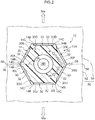
Fig. 2 is a cross-sectional view seen from an axial direction of the pipe coupling at cutting line A-A shown inFig. 1 . -
Fig. 3 is a perspective view of the pipe coupling shown inFig. 1 . -
Fig. 4(A) is a side view in which a torque input portion of the pipe coupling relating to the first embodiment is seen from the radial direction,Fig. 4 (B) is a side view of a torque input portion of a pipe coupling relating to a comparative example, andFig. 4 (C) is a correlation drawing of length in the axial direction of the torque input portion of the first embodiment and fastening limit torque (maximum torque) that is inputted to the torque input portion. -
Fig. 5 is a schematic drawing of the torque input portion of the pipe coupling relating to the first embodiment and a tool as seen from the axial direction, and illustrates application work. -
Fig. 6(A) is a perspective view of main portions of the torque input portion that shows the distribution of stress that arises due to input of torque, andFig. 6 (B) is a perspective view of main portions of the torque input portion that corresponds toFig. 6 (A) and shows a state in which a corner portion has broken. -
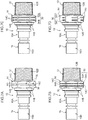
Fig. 7(A) is a side view of a pipe coupling that relates to a second embodiment of the present invention and is seen from a radial direction,Fig. 7 (B) is a side view of a pipe coupling that relates to a first modified example and corresponds toFig. 7 (A), Fig. 7 (C) is a side view of a pipe coupling that relates to a second modified example and corresponds toFig. 7 (A) , and -
Fig. 7 (D) is a side view of a pipe coupling that relates to a third modified example and corresponds toFig. 7 (A) . - A pipe coupling relating to a first embodiment of the present invention is described by using
Fig. 1 through Fig. 6 . Note that, in the drawings, reference letter Ac that is shown appropriately indicates the axial direction of the pipe coupling, and reference letter Ca indicates the radial direction heading toward the outer periphery from the axial center of the pipe coupling. - As shown in
Fig. 1 through Fig. 3 , apipe coupling 10 relating to the present embodiment has a pipe couplingmain body 10A that is formed of a resin material. The pipe couplingmain body 10A is structured to have a firstpipe connecting portion 12, atorque input portion 14 and a secondpipe connecting portion 16 that are arrayed successively along the axial direction Ac. In other words, the firstpipe connecting portion 12 is provided at one end portion in the axial direction Ac of the pipe couplingmain body 10A, and the secondpipe connecting portion 16 is provided at the other end portion in the axial direction Ac. Thetorque input portion 14 is provided at the intermediate portion in the axial direction Ac of the pipe couplingmain body 10A. InFig. 1 , thepipe coupling 10 connects afirst pipe body 20 shown by the one-dot chain line and asecond pipe body 22 shown by the two-dot chain line that serve as pipe bodies, and is structured as a flow path of fluid that flows between thefirst pipe body 20 and thesecond pipe body 22. The fluid includes liquids such as water, hot water, oil, liquid chemicals, or the like, or gasses such as air, gas or the like. Note that, in the present embodiment, the axial direction Ac is rectilinear, but the axial direction of a pipe coupling that is, for example, elbow-shaped, cheese-shaped, or curved may be bent, branched, or curved. Pipe couplings having these shapes and axial directions are included in thepipe coupling 10 relating to the present invention. Further, thefirst pipe body 20 is not limited to a pipe body that is a metal pipe or the like. Members that are connected in applications of general water / hot water supply pipes, such as other couplings or faucet fixtures, plumbing fixtures, water heaters and the like, are included as thefirst pipe body 20. The same holds for thesecond pipe body 22 as well. - In the present embodiment, because the pipe coupling
main body 10A is formed of a resin material, of course, the firstpipe connecting portion 12, thetorque input portion 14 and the secondpipe connecting portion 16 are formed of a resin material. In further detail, the firstpipe connecting portion 12, thetorque input portion 14 and the secondpipe connecting portion 16 are molded integrally by a molding method that uses a resin molding mold. Polyphenylenesulfide resin (PPS) is used as a suitable resin material, and this resin material has excellent heat resistance, chemical resistance and the like. Further, in a case in which glass fibers are mixed in a 40 wt.% ratio into the resin material, thepipe coupling 10 that has excellent cracking resistance and creep deformation resistance can be formed. - The first
pipe connecting portion 12 of thepipe coupling 10 is a hollow cylindrical shape. A pipe interior 12A of the firstpipe connecting portion 12 is structured as a flow path through which fluid flows in the axial direction. The outer peripheral region of the firstpipe connecting portion 12 is ascrew portion 12B that is screwed-into the first pipe body 20 (seeFig. 1 ). The diameter of thescrew portion 12B increases slightly from thefirst pipe body 20 side toward thetorque input portion 14 side, and thescrew portion 12B is structured by a tapered screw. - The
torque input portion 14 is provided at the side of the firstpipe connecting portion 12 that is opposite thefirst pipe body 20 side, and is a hollow polygonal tube shape whose axial center coincides with the axial center of the firstpipe connecting portion 12. A pipe interior 14A of thetorque input portion 14 communicates with the pipe interior 12A of the firstpipe connecting portion 12, and is structured as a flow path of fluid. Moreover, thepipe interior 14A is a tapered shape whose diameter decreases from the firstpipe connecting portion 12 side toward the secondpipe connecting portion 16 side. Pluraltool contacting surfaces 14B, to which the torque of screwing the firstpipe connecting portion 12 into thefirst pipe body 20 is inputted by a tool (seeFig. 5 , reference numeral 40), are provided along the peripheral direction at the outer periphery of thetorque input portion 14. In the present embodiment, thetool contacting surfaces 14B are structured as rectangular surfaces whose length direction is the peripheral direction and whose short-side direction is the axial direction Ac, and six of thetool contacting surfaces 14B are disposed in the peripheral direction. As shown inFig. 2 andFig. 3 , when viewed from the axial direction Ac, the contour shape of thetorque input portion 14 is structured by a hexagonal shape, in the same way as the contour shape of a hexagonal nut or the contour shape of a hexagonal bolt head. -
Corner portions 14C are provided at the peripheral direction ends of thetool contacting surfaces 14B, between one of thetool contacting surfaces 14B and the other onetool contacting surface 14B that is adjacent thereto in the peripheral direction. As shown inFig. 2 , inner angle α of thecorner portion 14C is set to be 120° here. Further, as shown inFig. 1 andFig. 3 , chamferedportions 14D are provided at the both end portions in the axial direction Ac of thecorner portion 14C. - As shown in
Fig. 1 andFig. 3 , the secondpipe connecting portion 16 is provided at the side of thetorque input portion 14 that is opposite the firstpipe connecting portion 12 side, and is a hollow cylindrical shape whose axial center coincides with the axial center of thetorque input portion 14. Apipe interior 16A at thetorque input portion 14 side of the secondpipe connecting portion 16 communicates with the pipe interior 14A of thetorque input portion 14, and is a tapered shape whose diameter decreases continuously with thepipe interior 14A. Apipe interior 16B, which is positioned at the intermediate portion in the axial direction Ac of the secondpipe connecting portion 16, communicates with the pipe interior 16A and is the same diameter along the axial direction Ac. Apipe interior 16C at thesecond pipe body 22 side of the secondpipe connecting portion 16 communicates with thepipe interior 16B, and is a tapered shape whose diameter increases from thepipe interior 16B toward thesecond pipe body 22. Thepipe interior 16A, thepipe interior 16B and thepipe interior 16C are structured as flow paths of fluid. - As shown in
Fig. 1 , thesecond pipe body 22 is inserted onto and connected with the outer peripheral region of the secondpipe connecting portion 16. Apositioning portion 16E, whose diameter is enlarged and that abuts the final end of thesecond pipe body 22 and that carries out positioning of the final end, is provided at the outer periphery of thetorque input portion 14 side of a joiningportion 16D.Groove portions 16F, whose diameters are reduced and that are disposed along the peripheral direction, are provided in the intermediate portion in the axial direction Ac of the joiningportion 16D. Although the arranged number thereof is not limited, here, two of thegroove portions 16F are provided so as to be apart in the axial direction Ac. O-rings 26 that are shown by the dashed lines are fit into thegroove portions 16F, and this is a structure in which the air-tightness or the water-tightness between the joiningportion 16D and thesecond pipe body 22 is improved by the O-rings 26. A press-fit portion 16G is provided between thetorque input portion 14 and thepositioning portion 16E of the secondpipe connecting portion 16. The press-fit portion 16G is a tapered shape whose diameter increases from thepositioning portion 16E toward thetorque input portion 14. - As shown in
Fig. 1 , at the secondpipe connecting portion 16, there is a structure in which a pipe-like body 24A, which is made of resin and is shown by an imaginary line, is provided at the periphery of thesecond pipe body 22 from the intermediate portion in the axial direction Ac of the joiningportion 16D to the press-fit portion 16G. The one end portion at thetorque input portion 14 side of the pipe-like body 24A is press-fit into the press-fit portion 16G, and the other end portion of the pipe-like body 24A is structured so as to surround the outer periphery of thesecond pipe body 22. Further, at the end portion in the axial direction Ac of the joiningportion 16D, arelease ring 24B that is made of resin and is shown by an imaginary line is provided at the periphery of thesecond pipe body 22, and alock ring 24D is provided between the pipe-like body 24A and therelease ring 24B. Moreover, acap 24C that is made of resin and is shown by an imaginary line is provided at the peripheries of the pipe-like body 24A and therelease ring 24B. Note that, at thepipe coupling 10 relating to the present embodiment, the above-described O-rings 26 andsecond pipe body 22 and the like are assembled in advance before application. - At the
pipe coupling 10 that is structured in this way, as shown inFig. 1 through Fig. 3 , aconcave portion 30, which is recessed in the radial direction Ca from thetool contacting surface 14B, is provided in thetool contacting surface 14B of thetorque input portion 14. In the present embodiment, theconcave portion 30 is structured by along groove 32 and along groove 34 whose length directions are the peripheral direction and whose short-side directions are the axial direction Ac. In further detail, theconcave portion 30 is structured so as to have two long grooves that are thelong groove 32 and thelong groove 34, which are disposed apart from one another in the axial direction Ac and parallel to one another, at each of all of (the six of the)tool contacting surfaces 14B. The respective groove lengths and groove widths of thelong groove 32 and thelong groove 34 are set to be the same dimensions. - Moreover, as shown in
Fig. 4(A) , in the axial direction Ac, length La from the firstpipe connecting portion 12 side end of thetool contacting surface 14B to thelong groove 32, length Lb from thelong groove 32 to thelong groove 34, and length Lc from thelong groove 34 to the secondpipe connecting portion 16 side end of thetool contacting surface 14B, are the same dimension. Length L1, which is the total of the length La, the length Lb and the length Lc, is the length in the axial direction Ac of thetool contacting surface 14B, excluding groove width W1 of thelong groove 32 and groove width W2 of the long groove 34 (excluding the concave portion 30). In other words, the length L1 is the total sum of the plural axial direction lengths Ln (length Ln is length La, length Lb or length Lc) of thetool contacting surface 14B that is partitioned by theconcave portion 30. The length (including the concave portion 30), which is obtained by adding the groove width W1 of thelong groove 32 and the groove width W2 of thelong groove 34 to the length L1, is length L2 in the axial direction Ac of thetool contacting surface 14B. - As shown in
Fig. 5 , theconcave portion 30 is structured such that, when excessive torque is inputted to thetorque input portion 14 by thetool 40, thecorner portion 14C of thetool contacting surface 14B is broken by thetool 40 before at least a portion of the pipe couplingmain body 10A reaches breakage. Here, breakage of the pipe couplingmain body 10A is a state that includes breakage on a small scale, such as cracks or the like. Further, breakage of thecorner portion 14C is a state in which thecorner portion 14C is crushed by thetool 40, or is deformed, and thetool 40 cannot catch on thecorner portion 14C. - In the present embodiment, the
concave portion 30 is not provided at thecorner portions 14C of thetool contacting surfaces 14B. In further detail, theconcave portion 30 is not provided atregions 36, which are surrounded by the dashed lines shown inFig. 1 andFig. 4(A) and that are between thelong groove 32, thelong groove 34 and the boundaries with the othertool contacting surfaces 14B that are adjacent in the peripheral direction to thetool contacting surface 14B. In other words, the respective regions of the peripheral end portions that are the length La, the length Lb, the length Lc of thetool contacting surface 14B, are connected together and are rib-shaped, and thelong groove 32 and thelong groove 34 are not provided at theregions 36. - Here, the contour shape of a resin molding mold (mold) 50 that is used in manufacturing the
pipe coupling 10 is shown as the imaginary line inFig. 2 . In the present embodiment, theresin molding mold 50 has afirst molding mold 52, which molds the half-region running along the axial direction Ac of thepipe coupling 10 including three of thetool contacting surfaces 14B of thetorque input portion 14, and asecond molding mold 54 that molds the other half-region of thepipe coupling 10 including the other threetool contacting surfaces 14B. In the present embodiment, partingline 56 that is the border between thefirst molding mold 52 and thesecond molding mold 54 is at a position facing thecorner portion 14C. In resin molding, thepipe coupling 10 is molded due to a resin material that has fluidity being injected into the cavity interior that is formed by thefirst molding mold 52 and thesecond molding mold 54, and the resin material being hardened. In the present embodiment, as shown inFig. 1 andFig. 2 , aninjection gate 58, which serves as a resin injection opening of theresin molding mold 50, is provided at a position corresponding to one of thecorner portions 14C along theparting line 56 of thetorque input portion 14. - As shown in
Fig. 2 , as seen from the axial direction Ac, flow R of the resin material is divided in two upward and downward at the periphery of thepipe interior 14A from theinjection gate 58, and thereafter, is joined into one. This region that is joined and hardened is a weld portion WL, and, as shown by the one-dot chain line, the weld portion WL is formed along the radial direction Ca of thetorque input portion 14. The weld portion WL is formed to be at the side of the pipe interior 14A which side is exactly opposite the position of theinjection gate 58. The region at which this weld portion WL is formed is thecorner portion 14C, and, as described above, by making thecorner portion 14C be theregions 36, theconcave portion 30 is not provided at theregions 36. - Further, because the
pipe coupling 10 is molded by theresin molding mold 50, as shown inFig. 2 , the surface directions ofinner walls 30B through 30E, 30H through 30K, which run along the short-side directions of thelong grooves 32 and the long grooves 34 (the axial direction Ac), coincide with mold releasing direction Ma of theresin molding mold 50. Due thereto, release from the mold is possible without catching on theresin molding mold 50. In addition, surface directions ofinner walls long grooves 32 and thelong grooves 34, are orthogonal to the mold releasing direction Ma. - At the
pipe coupling 10 relating to the present embodiment, as shown inFig. 1 through Fig. 3 , thescrew portion 12B is provided at one end portion in the axial direction Ac of the pipe couplingmain body 10A, and thetorque input portion 14 is provided at the intermediate portion in the axial direction Ac of the pipe couplingmain body 10A. Thetorque input portion 14 is a polygonal shape having, in the peripheral direction thereof, the pluraltool contacting surfaces 14B to which torque is inputted. Further, theconcave portion 30 is provided in thetool contacting surfaces 14B. - Here, the pipe coupling
main body portion 10A is molded of a resin material. Namely, the pipe couplingmain body 10A, thescrew portion 12B, thetorque input portion 14, and the joiningportion 16D are molded integrally as a single part from the same resin material. Therefore, the number of parts of thepipe coupling 10 can be reduced, and the structure of thepipe coupling 10 can be made to be simple. Moreover, because the number of parts is reduced and the structure is made to be simple, the manufacturing cost and the parts costs of thepipe coupling 10 can be made to be inexpensive. Further, because the pipe couplingmain body 10A is molded of a resin material that is light-weight as compared with a metal material, lightening of the weight of thepipe coupling 10 can be devised. In addition, because regions that are insert-molded of different types of materials do not exist at thepipe coupling 10, separation between different types of materials does not arise when torque is inputted to thetorque input portion 14. - Further, at the
pipe coupling 10 relating to the present embodiment, when excessive fastening torque (maximum torque Tmax) that is greater than prescribed is inputted to thetorque input portion 14, thecorner portion 14C of the polygonal shape of thetorque input portion 14 is broken due to theconcave portion 30. For example, thetool 40 that is shown inFig. 5 is used for the inputting of torque, and thetool 40 is a monkey wrench here. The monkey wrench is structured to have a fixedjaw 42 and anadjustable jaw 44 that nip two opposingtool contacting surfaces 14B of thetorque input portion 14, anadjusting gear 46 by which the position of theadjustable jaw 44 can be adjusted, and ahandle 48 by which manual torque is applied. In the present embodiment, because thescrew portion 12B is a right screw, when viewing the firstpipe connecting portion 12 side from thetorque input portion 14 side in the axial direction Ac, thetool 40 is rotated in the clockwise direction, and thescrew portion 12B is screwed-in into thefirst pipe body 20. At this time, torque T is inputted to thetorque input portion 14 from thetool 40 in the rotating direction of thetool 40, and the torque T is applied to thetool contacting surfaces 14B and thecorner portions 14C. In a case in which excessive fastening torque that is greater than prescribed is inputted to thetorque input portion 14 by using thetool 40, stress concentrates at thecorner portion 14C, and thecorner portion 14C is broken, and thetool 40 cannot catch on thecorner portion 14C, and therefore, excessive fastening torque is not inputted to thetorque input portion 14. - Further, at the
pipe coupling 10 relating to the present embodiment, there is a structure in which theconcave portion 30 causes thecorner portion 14C to break before thescrew portion 12B or the joiningportion 16D reaches breakage. As shown inFig. 1 through Fig. 3 andFig. 4(A) , theconcave portion 30 is provided at thetorque input portion 14, and theconcave portion 30 is structured by thelong groove 32, thelong groove 34 that are concave and are recessed in the radial direction from thetool contacting surface 14B. When the torque T is inputted to thetorque input portion 14 by using thetool 40, as shown inFig. 6(A) , stresses S1 through S3 are applied to thetool contacting surfaces 14B that contact the fixed jaw and theadjustable jaw 44 of thetool 40. In order to clarify the strengths and the state of distribution of the stresses, for convenience, the stresses S1 through S3 are shown so as to be divided into three levels. The stress S3 is the largest stress, and the stresses S2, S1 are successively smaller stresses. The large stress S3 arises at thecorner portion 14C at the peripheral direction final end to which the torque T is applied from the peripheral direction intermediate portion of thetool contacting surface 14B that contacts thetool 40. The stress S2 concentrates at thecorner portion 14C of thetorque input portion 14. The stress S1 arises from the peripheral direction intermediate portion of thetool contacting surface 14B that contacts thetool 40, to thetool contacting surface 14B that does not contact thetool 40 and is at the next stage in the peripheral direction. Before at least one of thescrew portion 12B and the press-fit portion 16G in particular of the joiningportion 16D that are shown inFig. 1 reaches breakage, as shown inFig. 6(B) , thecorner portion 14C of the peripheral direction end of thetool contacting surface 14B is broken by thetool 40 due to theconcave portion 30. InFig. 6(B) , the broken region is indicated byreference numeral 14E. Therefore, because catching of thetool 40 on thecorner portion 14C no longer occurs, after thecorner portion 14C is broken, excessive torque, which is such that thescrew portion 12B or the press-fit portion 16G reaches breakage, is not inputted to thetorque input portion 14. Accordingly, breakage of at least one of thescrew portion 12B or the press-fit portion 16G can be prevented in advance. - A comparative example is described here. At a
pipe coupling 100 shown inFig. 4(B) , theconcave portion 30 of the present embodiment is not provided at atorque input portion 104. When excessive torque was inputted to thetorque input portion 104, damage such as cracking, destruction, and the like was confirmed atregion 102E of a firstpipe connecting portion 102 that has a screw portion. Further, at thepipe coupling 100, similarly, when excessive torque was inputted to thetorque input portion 104, damage such as cracking, destruction, and the like was confirmed atregion 106E of a press-fit portion in a vicinity of the root of a secondpipe coupling portion 106. - Moreover, at the
pipe coupling 10 relating to the present embodiment, the correlation relationship between the length L1 (mm) of thetool contacting surface 14B except for theconcave portion 30 in a case in which the length in the peripheral direction of thetool contacting surface 14B is constant, and the fastening limit torque Tmax (Nm) that is the maximum torque, is shown inFig. 4(C) . The length L1 is the sum total of the length La, the length Lb and the length Lc. When the length L1 was increased to 1.5 mm, 3 mm, and 5 mm (the surface area of thetool contacting surface 14B increases in accordance with the increase in the length L1), comparative regions where the fastening limit torque Tmax increased to approximately 20 Nm, approximately 40 Nm and approximately 60 Nm were discovered. In addition, when the length L1 exceeded 6 mm, a saturation region where the fastening limit torque Tmax is constant at less than approximately 70 Nm was discovered. When the surface area of thetool contacting surface 14B is set in the range of the saturation region, dispersion in the prescribed value of the torque can be effectively reduced, and therefore, thecorner portion 14C can be broken as planned before thescrew portion 12B or the press-fit portion 16G reaches breakage. At thepipe coupling 10 relating to the present embodiment, the length in the peripheral direction of thetool contacting surface 14B is constant at approximately 14 mm, and the length La, the length Lb and the length Lc are respectively 2 mm equally, and the length L1 of thetool contacting surface 14B is set to 6 mm. Further, in the present embodiment, the groove width W1 and the groove width W2 of theconcave portion 30 are set to 1 mm equally. The practical range of the length La, the length Lb, the length Lc (the length Ln) is 1 mm to 3 mm, and the practical range of the groove width W1, the groove width W2 is 1 mm to 2 mm. Accordingly, the practical range of the length L1 is 3 mm to 9 mm. - In addition, at the
pipe coupling 10 relating to the present embodiment, the length L1 in the axial direction Ac of thetool contacting surface 14B except for theconcave portion 30 can be set to be, for example, a length that is easy for thetool 40 to catch on. When the length L1 is set to 6 mm as described above, the length L2 in the axial direction Ac of thetool contacting surface 14B including the concave portions 30 (to which the 2 mm of the groove width W1 and the groove width W2 are added) is 8 mm. At a monkey wrench that is an entirely forged product specified by Japanese Industrial Standard JIS B4604 and that has a 23° opening and is 150 mm, maximum dimension (a2) of the thickness of the fixedjaw 42 or theadjustable jaw 44 is 11 mm, and, at a monkey wrench of 200 mm, the maximum dimension (a2) is 14 mm. Therefore, the length L2 is the same dimension as or is a dimension slightly smaller than the dimension of the thickness of the fixedjaw 42 of thetool 40, and thus, the applicability of the pipe coupling can be improved. Note that the practical range of the length L2 is 5 mm to 13 mm. - Further, at the
pipe coupling 10 relating to the present embodiment, the division value, which is obtained by the length L1 in the axial direction Ac of thetool contacting surface 14B except for theconcave portion 30 being divided by the length L2 in the axial direction Ac of thetool contacting surface 14B including theconcave portion 30, is 0.18 to 0.88. When the length L2 is set to 8 mm whose frequency of usage is high, at thepipe coupling 10 that is made of resin and that is used at a water pipe for example, 20 Nm is needed as fastening torque that is suitable for preventing water leakage. As shown inFig. 4(C) , the lower limit value of the length L1 at which a torque of 20 Nm is allowable is 1.5 mm. Therefore, if the length L1 is 1.5 mm and the length L2 is 8 mm, the division value is 0.18. At this time, the total of the groove width W1 and the groove width W2 is 6.5 mm. On the other hand, because there is the need to stop before 65 Nm that is an excessive fastening torque, as shown inFig. 4(C) , the upper limit value of the length L1 is 7 mm. At this time, if the length L1 is 7 mm and the length L2 is 8 mm, the division value is 0.88, and the total of the groove width W1 and the groove width W2 is 1 mm. Namely, because the division value is made to be greater than or equal to 0.18, torque that is suited to being able to prevent water leakage can be inputted to thetorque input portion 14. On the other hand, because the division value is made to be less than or equal to 0.88, in a case in which excessive torque that is such that the pipe couplingmain body 10A reaches breakage is inputted to thetorque input portion 14, stress concentrates at thecorner portion 14C of thetorque input portion 14 due to theconcave portion 30, and breakage arises at thecorner portion 14C. Therefore, because thetool 40 does not catch on thecorner portion 14C, excessive torque is not inputted to thetorque input portion 14. - At the
pipe coupling 10 relating to the present embodiment, the division value is made to be 0.62 to 0.75. Around 55 Nm is needed in order to increase the fastening torque and reliably prevent water leakage. As shown inFig. 4(C) ,5 mm is needed as the length L1 in order to make this torque be the fastening torque. If the length L1 is 5 mm and the length L2 is 8 mm, the division value is 0.62. On the other hand, in order to obtain a suitable fastening torque in a range not reaching 65 Nm, it is preferable to set the length L1 to 6 mm at which the fastening limit torque is made to be around 60 Nm. If the length L1 is 6 mm and the length L2 is 8 mm, the division value is 0.75. Namely, by making the division value be in the range of the above-described numerical values, within a practical range, a reliable fastening torque can be inputted to thetorque input portion 14, and excessive torque that reaches breakage of the pipe couplingmain body 10A is not inputted to thetorque input portion 14. - Moreover, at the
pipe coupling 10 relating to the present embodiment, as shown inFig. 4(C) , there was discovered a saturation region in which the maximum torque at which the pipe couplingmain body 10A reaches breakage (the fastening limit torque) becomes constant, with respect to an increase in the surface area of thetool contacting surface 14B. When the surface area of thetool contacting surface 14B is set in the saturation region, dispersion in the maximum torque can be reduced effectively. Therefore, thecorner portion 14C can be broken as planned before the pipe couplingmain body 10A reaches breakage, and therefore, suitable torque is inputted to thetorque input portion 14, and excessive torque is not inputted. In addition, because the length L1 can be set to a length that is easy for thetool 40 to catch on for example, the applicability of thepipe coupling 10 can be improved. - Further, at the
pipe coupling 10 relating to the present embodiment, the value (Ln/L2), which is obtained by the above-described length Ln (the length La, the length Lb or the length Lc) being divided by the length L2, is set to be less than or equal to 1/3. Because theconcave portion 30 is provided at thetool contacting surface 14B as described above, thecorner portion 14C can be broken before thescrew portion 12B or in particular the press-fit portion 16G of the joiningportion 16D reaches breakage. In addition, because theconcave portion 30 is provided at thetool contacting surface 14B, the wall thickness (the thickness of the resin material) in the axial direction Ac and the radial direction Ca of thetorque input portion 14 can be made to be thin locally. When the wall thickness of thetorque input portion 14 is made to be thin locally, the pressure that is applied to the resin material that is injected into theresin molding mold 50 increases. Therefore, discharging of air, which has mixed in theresin molding mold 50, to the exterior of theresin molding mold 50 is promoted, and thus, the generation of voids at the pipe couplingmain body 10A after resin molding can be suppressed effectively. - Moreover, at the
pipe coupling 10 relating to the present embodiment, due to the length Ln and the length L2 being set to the above-described numerical values, the above-described operation and effects can be achieved within a practical range. - Further, at the
pipe coupling 10 relating to the present embodiment, as shown inFig. 1 through Fig. 3 , because theconcave portion 30 is provided at thetool contacting surface 14B except for thecorner portions 14C, theconcave portion 30 is not provided at thecorner portions 14C. Therefore, the strength of thecorner portions 14C of thetorque input portion 14 can be increased. For example, in a case in which there is an upper limit of the length L2 in the axial direction Ac of thetool contacting surface 14B including theconcave portion 30, thescrew portion 12B can be screwed-into and shut tightly with thefirst pipe body 20 by a suitable torque, while the length L2 is set within the range of the upper limit. On the other hand, when excessive fastening torque is inputted, thecorner portion 14C is broken, and excessive fastening torque is not inputted to thetorque input portion 14. - Further, at the
pipe coupling 10 relating to the present embodiment, as shown inFig. 2 , the pipe couplingmain body 10A is formed by integral molding of a resin material by theresin molding mold 50. Theinjection gate 58 is provided at at least one place at theresin molding mold 50, and a region that corresponds to theinjection gate 58 is provided at the outer periphery of thetorque input portion 14. Here, theconcave portion 30 is provided at thetool contacting surfaces 14B excepting the weld portion WL at which the resin material, which has been injected-in from theinjection gate 58, joins together. Namely, the weld portion WL is provided at a region of thetorque input portion 14 that is other than at theconcave portion 30 and where the wall thickness in the radial direction Ca is thick. Therefore, because the joined surface area of the weld portion WL can be increased, the strength of the weld portion WL can be improved, and the weld portion WL becoming the origin of destruction can be effectively suppressed or prevented. - The
pipe coupling 10 relating to a second embodiment of the present invention is described by usingFig. 7 . Note that, in the description of the present embodiment, structures having the same functions as those of thepipe coupling 10 relating to the first embodiment are denoted by the same reference numerals, and repeat description is omitted. - In the
pipe coupling 10 relating to the present embodiment that is shown inFig. 7(A) , theconcave portion 30 is structured by onelong groove 38 that is provided at thetool contacting surface 14B of thetorque input portion 14. The length direction of thelong groove 38 is the peripheral direction, and thelong groove 38 has groove width W3 that is wider than the groove width W1 of the above-describedlong groove 32 and the groove width W2 of the long groove 34 (e.g., the groove width W3 is set to 2 mm). Note that, in thepipe coupling 10 relating to the present embodiment, theconcave portion 30 is structured by the onelong groove 38, and, in thepipe coupling 10 relating to the above-described first embodiment, theconcave portion 30 is structured by the two long grooves that are thelong groove 32 and thelong groove 34. In the present invention, theconcave portion 30 may be structured to include three or more long grooves in the axial direction Ac. - In the
pipe coupling 10 that relates to a first modified example of the present embodiment and is shown inFig. 7(B) , theconcave portion 30 is structured by along groove 32A and along groove 34A that are connected together at the respectivetool contacting surfaces 14B that are adjacent in the peripheral direction. Namely, thelong groove 32A and thelong groove 34A are annular shapes that are continuous in the peripheral direction. In the first modified example, theconcave portion 30 is provided also at thecorner portions 14C (the regions 36) of thetorque input portion 14. - In the
pipe coupling 10 that relates to a second modified example of the present embodiment and is shown inFig. 7(C) , theconcave portion 30 is structured by along groove 32B and along groove 34B that are not shaped as rectangular openings, and whose peripheral direction both ends are arc-shaped. - In the
pipe coupling 10 that relates to a third modified example of the present embodiment and is shown inFig. 7(D) , theconcave portion 30 is structured by along groove 32C and along groove 34C that are provided in a vicinity of thecorner portion 14C at which a concentration of stress arises and that should break when excessive torque is inputted. In further detail, theconcave portion 30 is provided from the peripheral direction intermediate portion of thetool contacting surface 14B to the region of the peripheral direction final end portion that thetool 40 catches-on (the region at which the stress S2 and the stress S3 that are shown inFig. 6(A) arise). - In accordance with the
pipe coupling 10 relating to the present embodiment and thepipe couplings 10 relating to the first modified example through the third modified example, similarly to the operation and effects that are obtained by thepipe coupling 10 relating to the first embodiment, operation and effects are obtained that the number of parts can be reduced and the structure can be made simple. Further, in accordance with thepipe coupling 10, the operation and effects are obtained that breakage of thescrew portion 12B or the press-fit portion 16G with respect to the input of excessive torque can be prevented in advance, without deteriorating the applicability. Moreover, in accordance with thepipe coupling 10, because thepipe coupling 10 is molded of a resin material, lightening of the weight can be devised. - The present invention is not limited to the above-described embodiments, and can be changed in various ways within a scope that does not depart from the gist thereof. For example, in the present invention, the contour shape of the torque input portion seen from the axial direction may be made to be a polygonal shape that is a quadrangular shape, an octagonal shape, or more. Namely, it suffices for the torque input portion to have at least two or more tool contacting surfaces in the peripheral direction. Further, in the present invention, in the case of a hexagonal torque input portion for example, concave portions may be provided at only two tool contacting surfaces that oppose one another, or concave portions may be provided at a total of four tool contacting surfaces that oppose one another at two places.
- Moreover, in the present invention, the shapes of the plural long grooves, which are are disposed in the axial direction, of the concave portion may be different shapes. Further, in the present invention, the long grooves of the concave portion may be long grooves that have the shape of an oval opening. Moreover, the present invention is not limited to long grooves, and the concave portion may be structured by grooves that are concave and that have an opening shape that is square, polygonal, circular, star-shaped, or the like.
- In the pipe couplings relating to the above-described embodiments, the tool contacting surfaces of the torque input portion are structured by flat surfaces. However, in the present invention, there may be tool contacting surfaces at which shallow grooves or a pattern that are smaller than concave portions are provided and serve as anti-slip portions.
- Further, in the present invention, the injection gate may be provided at one place of the resin molding mold, in correspondence with the position of the peripheral direction intermediate portion of the tool contacting surface. In this case, because the weld portion is formed at the peripheral direction intermediate portion of the tool contacting surface, the concave portion is provided at the tool contacting surface at other than this region. Note that, at the resin molding mold, the number of injection gates is not limited to one place, and injection gates at two or more places may be provided.
- Moreover, the screw portions of the pipe couplings relating to the above-described embodiments are male screws that are tapered shapes. However, in the present invention, this may be replaced by various types of screw shapes such as a male screw that is a parallel screw, a female screw that is a tapered shape, a female screw that is a parallel screw, or the like.
-
- 10
- pipe coupling
- 10A
- pipe coupling main body
- 12
- first pipe connecting portion
- 12B
- screw portion
- 14
- torque input portion
- 14B
- tool contacting surface
- 14C
- corner portion
- 16
- second pipe connecting portion
- 16D
- joining portion
- 16G
- press-fit portion
- 30
- concave portion
- 32, 32A
- through 32C, 34, 34A through 34C, 38 long groove
- 40
- tool
- 50
- resin molding mold
Claims (8)
- A pipe coupling comprising:a pipe coupling main body that is pipe-shaped;a screw portion that is provided at an axial direction one end portion of the pipe coupling main body;a torque input portion that is polygonal, is provided at an axial direction intermediate portion of the pipe coupling main body, and has, in a peripheral direction, a plurality of tool contacting surfaces to which torque is inputted; anda concave portion that is provided in the tool contacting surfaces and that is recessed in a radial direction from the tool contacting surfaces,wherein a division value that is obtained by a length L1 in an axial direction of the tool contacting surfaces except for the concave portion being divided by a length L2 in the axial direction of the tool contacting surfaces including the concave portion is from 0.18 to 0.88.
- The pipe coupling of Claim 1, wherein the division value is from 0.62 to 0.75.
- The pipe coupling of Claim 1 or Claim 2, wherein the pipe coupling main body, the screw portion and the torque input portion are molded integrally of a resin material.
- The pipe coupling of any one of Claim 1 through Claim 3, wherein the length L1 is set in a saturation range in which torque, by which the pipe coupling main body reaches breakage, is constant with respect to an increase in the length L1.
- The pipe coupling of any one of Claim 1 through Claim 4, wherein the length L1 is a sum total of a plurality of lengths Ln in the axial direction of the tool contacting surfaces that are partitioned by the concave portion, and a division value obtained by dividing the length Ln by the length L2 is set to be less than or equal to 1/3.
- The pipe coupling of Claim 5, wherein the length Ln is in a range of from 1 mm to 3 mm, and the length L2 is in a range of from 5 mm to 13 mm.
- The pipe coupling of any one of Claim 1 through Claim 6, wherein the concave portion is provided at the tool contacting surfaces except for at corner portions of a polygonal shape of the torque input portion.
- The pipe coupling of any one of Claim 1 through Claim 7, wherein:the pipe coupling main body is formed by integral molding of a resin material by a mold, anda region that corresponds to a resin injection opening of the mold is provided at at least one place at an outer periphery of the torque input portion, and the concave portion is provided at the tool contacting surfaces except for at a weld portion where the resin material, which has been injected in from the resin injection opening, joins together.
Applications Claiming Priority (2)
| Application Number | Priority Date | Filing Date | Title |
|---|---|---|---|
| JP2014159072A JP6680456B2 (en) | 2014-08-04 | 2014-08-04 | Pipe fitting |
| PCT/JP2015/070453 WO2016021389A1 (en) | 2014-08-04 | 2015-07-16 | Pipe joint |
Publications (3)
| Publication Number | Publication Date |
|---|---|
| EP3179147A1 true EP3179147A1 (en) | 2017-06-14 |
| EP3179147A4 EP3179147A4 (en) | 2018-08-29 |
| EP3179147B1 EP3179147B1 (en) | 2019-10-16 |
Family
ID=55263662
Family Applications (1)
| Application Number | Title | Priority Date | Filing Date |
|---|---|---|---|
| EP15829086.6A Active EP3179147B1 (en) | 2014-08-04 | 2015-07-16 | Pipe joint |
Country Status (5)
| Country | Link |
|---|---|
| EP (1) | EP3179147B1 (en) |
| JP (1) | JP6680456B2 (en) |
| CN (1) | CN106687731B (en) |
| TW (1) | TWI671485B (en) |
| WO (1) | WO2016021389A1 (en) |
Families Citing this family (9)
| Publication number | Priority date | Publication date | Assignee | Title |
|---|---|---|---|---|
| JP2018025278A (en) * | 2016-08-12 | 2018-02-15 | 株式会社ブリヂストン | Pipe joint connection structure |
| CN107336373A (en) * | 2016-12-19 | 2017-11-10 | 东莞市昶丰机械科技有限公司 | A kind of new-type atmosphere protection titanium alloy banbury |
| JP6846290B2 (en) * | 2017-06-02 | 2021-03-24 | 株式会社ブリヂストン | Manufacturing method for injection molding dies, resin members, and resin products |
| JP6779176B2 (en) * | 2017-06-02 | 2020-11-04 | 株式会社ブリヂストン | Resin member |
| JP6782195B2 (en) * | 2017-06-02 | 2020-11-11 | 株式会社ブリヂストン | Manufacturing method for injection molding dies, resin members, and resin products |
| JP6823546B2 (en) * | 2017-06-02 | 2021-02-03 | 株式会社ブリヂストン | Manufacturing method for injection molding dies, resin members, and resin products |
| TWI728455B (en) * | 2019-09-04 | 2021-05-21 | 艋庫拉制震股份有限公司 | Turning tool water outlet device |
| CN117020168B (en) * | 2023-09-13 | 2025-12-26 | 昆山艾特利热导科技有限公司 | A five-segment heat pipe sealing mold |
| CN119458227B (en) * | 2024-11-20 | 2026-01-20 | 宁波佳音机电科技股份有限公司 | PE pipe pull-out auxiliary tool |
Family Cites Families (13)
| Publication number | Priority date | Publication date | Assignee | Title |
|---|---|---|---|---|
| JPH06105115B2 (en) * | 1988-12-15 | 1994-12-21 | 積水化学工業株式会社 | Pipe fitting |
| JP3215319B2 (en) * | 1996-03-14 | 2001-10-02 | 株式会社青山製作所 | Plug breather |
| JPH11320598A (en) * | 1998-05-19 | 1999-11-24 | Mitsubishi Eng Plast Corp | Molded product made of polyamide resin with weld |
| CN2374722Y (en) * | 1998-10-23 | 2000-04-19 | 刘家荣 | Fitting for the valve body |
| CN2384088Y (en) * | 1999-07-23 | 2000-06-21 | 昆山天星水暖有限公司 | Pipe joint |
| FI115665B (en) * | 2002-11-08 | 2005-06-15 | Uponor Innovation Ab | A connecting piece |
| JP2005163938A (en) * | 2003-12-03 | 2005-06-23 | Sekisui Chem Co Ltd | Pipe fitting |
| JP4692007B2 (en) * | 2005-02-16 | 2011-06-01 | Tdk株式会社 | Molding method |
| JP4964678B2 (en) * | 2007-05-29 | 2012-07-04 | 井上スダレ株式会社 | Pipe fitting body |
| JP2012219942A (en) * | 2011-04-11 | 2012-11-12 | Mitsubishi Plastics Inc | Joint for piping and joint structure |
| DE102011056601A1 (en) * | 2011-12-19 | 2013-06-20 | Voss Automotive Gmbh | Hollow cylindrical screw part and method for its production |
| JP6071445B2 (en) * | 2012-11-08 | 2017-02-01 | 株式会社ブリヂストン | Piping joint |
| JP5977650B2 (en) * | 2012-11-12 | 2016-08-24 | 株式会社ブリヂストン | Hose fittings |
-
2014
- 2014-08-04 JP JP2014159072A patent/JP6680456B2/en active Active
-
2015
- 2015-07-16 CN CN201580048684.5A patent/CN106687731B/en not_active Expired - Fee Related
- 2015-07-16 WO PCT/JP2015/070453 patent/WO2016021389A1/en not_active Ceased
- 2015-07-16 EP EP15829086.6A patent/EP3179147B1/en active Active
- 2015-07-30 TW TW104124693A patent/TWI671485B/en not_active IP Right Cessation
Also Published As
| Publication number | Publication date |
|---|---|
| CN106687731A (en) | 2017-05-17 |
| TWI671485B (en) | 2019-09-11 |
| EP3179147A4 (en) | 2018-08-29 |
| JP2016035310A (en) | 2016-03-17 |
| CN106687731B (en) | 2020-06-16 |
| JP6680456B2 (en) | 2020-04-15 |
| TW201616029A (en) | 2016-05-01 |
| EP3179147B1 (en) | 2019-10-16 |
| WO2016021389A1 (en) | 2016-02-11 |
Similar Documents
| Publication | Publication Date | Title |
|---|---|---|
| EP3179147B1 (en) | Pipe joint | |
| CN105190148B (en) | Pipe connection | |
| CN108368731B (en) | Threaded connections including intermediate shoulders | |
| TWI616609B (en) | Pipe connection | |
| JP4253026B2 (en) | Resin pipe joint and manufacturing method thereof | |
| US11035502B2 (en) | Compression resistant threaded connection | |
| US20210054932A1 (en) | Gasket and flow passage connector structure | |
| KR101708477B1 (en) | Reinforcing rod a coupling device | |
| JP6071445B2 (en) | Piping joint | |
| JP5923578B2 (en) | Resin pipe fittings | |
| KR102865890B1 (en) | pipe joints | |
| KR101232319B1 (en) | Pipe connector | |
| RU2371629C1 (en) | Device for protection of internal and external thread of drilling pipes with welded locks | |
| JP2016035313A (en) | Pipe joint member | |
| KR101308401B1 (en) | Water pipe connecting assembly having high strength connector | |
| JP2006316806A (en) | Connection structure between each fluid instruments | |
| JP4949486B2 (en) | Reinforcing bar joint structure | |
| KR101906327B1 (en) | Joining part having sleeve | |
| JP6497861B2 (en) | Pipe fitting | |
| US12281730B2 (en) | Tube fitting | |
| KR200470676Y1 (en) | Insert part for pipe joint | |
| KR20080005468U (en) | Tube fittings | |
| JP6407611B2 (en) | Pipe fitting | |
| JP2018054019A (en) | Pipe joint | |
| JP2017227242A (en) | Pipe joint and pipe joint connection structure |
Legal Events
| Date | Code | Title | Description |
|---|---|---|---|
| STAA | Information on the status of an ep patent application or granted ep patent |
Free format text: STATUS: THE INTERNATIONAL PUBLICATION HAS BEEN MADE |
|
| PUAI | Public reference made under article 153(3) epc to a published international application that has entered the european phase |
Free format text: ORIGINAL CODE: 0009012 |
|
| STAA | Information on the status of an ep patent application or granted ep patent |
Free format text: STATUS: REQUEST FOR EXAMINATION WAS MADE |
|
| 17P | Request for examination filed |
Effective date: 20170221 |
|
| AK | Designated contracting states |
Kind code of ref document: A1 Designated state(s): AL AT BE BG CH CY CZ DE DK EE ES FI FR GB GR HR HU IE IS IT LI LT LU LV MC MK MT NL NO PL PT RO RS SE SI SK SM TR |
|
| AX | Request for extension of the european patent |
Extension state: BA ME |
|
| DAV | Request for validation of the european patent (deleted) | ||
| DAX | Request for extension of the european patent (deleted) | ||
| R17P | Request for examination filed (corrected) |
Effective date: 20170221 |
|
| RIC1 | Information provided on ipc code assigned before grant |
Ipc: B29C 45/27 20060101ALN20180419BHEP Ipc: F16L 15/00 20060101AFI20180419BHEP |
|
| A4 | Supplementary search report drawn up and despatched |
Effective date: 20180801 |
|
| RIC1 | Information provided on ipc code assigned before grant |
Ipc: F16L 15/00 20060101AFI20180726BHEP Ipc: B29C 45/27 20060101ALN20180726BHEP |
|
| GRAP | Despatch of communication of intention to grant a patent |
Free format text: ORIGINAL CODE: EPIDOSNIGR1 |
|
| STAA | Information on the status of an ep patent application or granted ep patent |
Free format text: STATUS: GRANT OF PATENT IS INTENDED |
|
| RIC1 | Information provided on ipc code assigned before grant |
Ipc: F16L 15/00 20060101AFI20190408BHEP Ipc: B29C 45/27 20060101ALN20190408BHEP |
|
| INTG | Intention to grant announced |
Effective date: 20190430 |
|
| GRAS | Grant fee paid |
Free format text: ORIGINAL CODE: EPIDOSNIGR3 |
|
| GRAA | (expected) grant |
Free format text: ORIGINAL CODE: 0009210 |
|
| STAA | Information on the status of an ep patent application or granted ep patent |
Free format text: STATUS: THE PATENT HAS BEEN GRANTED |
|
| AK | Designated contracting states |
Kind code of ref document: B1 Designated state(s): AL AT BE BG CH CY CZ DE DK EE ES FI FR GB GR HR HU IE IS IT LI LT LU LV MC MK MT NL NO PL PT RO RS SE SI SK SM TR |
|
| REG | Reference to a national code |
Ref country code: GB Ref legal event code: FG4D |
|
| REG | Reference to a national code |
Ref country code: CH Ref legal event code: EP |
|
| REG | Reference to a national code |
Ref country code: DE Ref legal event code: R096 Ref document number: 602015040021 Country of ref document: DE |
|
| REG | Reference to a national code |
Ref country code: IE Ref legal event code: FG4D |
|
| REG | Reference to a national code |
Ref country code: AT Ref legal event code: REF Ref document number: 1191611 Country of ref document: AT Kind code of ref document: T Effective date: 20191115 |
|
| REG | Reference to a national code |
Ref country code: NL Ref legal event code: MP Effective date: 20191016 |
|
| REG | Reference to a national code |
Ref country code: LT Ref legal event code: MG4D |
|
| REG | Reference to a national code |
Ref country code: AT Ref legal event code: MK05 Ref document number: 1191611 Country of ref document: AT Kind code of ref document: T Effective date: 20191016 |
|
| PG25 | Lapsed in a contracting state [announced via postgrant information from national office to epo] |
Ref country code: PT Free format text: LAPSE BECAUSE OF FAILURE TO SUBMIT A TRANSLATION OF THE DESCRIPTION OR TO PAY THE FEE WITHIN THE PRESCRIBED TIME-LIMIT Effective date: 20200217 Ref country code: FI Free format text: LAPSE BECAUSE OF FAILURE TO SUBMIT A TRANSLATION OF THE DESCRIPTION OR TO PAY THE FEE WITHIN THE PRESCRIBED TIME-LIMIT Effective date: 20191016 Ref country code: BG Free format text: LAPSE BECAUSE OF FAILURE TO SUBMIT A TRANSLATION OF THE DESCRIPTION OR TO PAY THE FEE WITHIN THE PRESCRIBED TIME-LIMIT Effective date: 20200116 Ref country code: AT Free format text: LAPSE BECAUSE OF FAILURE TO SUBMIT A TRANSLATION OF THE DESCRIPTION OR TO PAY THE FEE WITHIN THE PRESCRIBED TIME-LIMIT Effective date: 20191016 Ref country code: LT Free format text: LAPSE BECAUSE OF FAILURE TO SUBMIT A TRANSLATION OF THE DESCRIPTION OR TO PAY THE FEE WITHIN THE PRESCRIBED TIME-LIMIT Effective date: 20191016 Ref country code: PL Free format text: LAPSE BECAUSE OF FAILURE TO SUBMIT A TRANSLATION OF THE DESCRIPTION OR TO PAY THE FEE WITHIN THE PRESCRIBED TIME-LIMIT Effective date: 20191016 Ref country code: NO Free format text: LAPSE BECAUSE OF FAILURE TO SUBMIT A TRANSLATION OF THE DESCRIPTION OR TO PAY THE FEE WITHIN THE PRESCRIBED TIME-LIMIT Effective date: 20200116 Ref country code: NL Free format text: LAPSE BECAUSE OF FAILURE TO SUBMIT A TRANSLATION OF THE DESCRIPTION OR TO PAY THE FEE WITHIN THE PRESCRIBED TIME-LIMIT Effective date: 20191016 Ref country code: LV Free format text: LAPSE BECAUSE OF FAILURE TO SUBMIT A TRANSLATION OF THE DESCRIPTION OR TO PAY THE FEE WITHIN THE PRESCRIBED TIME-LIMIT Effective date: 20191016 Ref country code: SE Free format text: LAPSE BECAUSE OF FAILURE TO SUBMIT A TRANSLATION OF THE DESCRIPTION OR TO PAY THE FEE WITHIN THE PRESCRIBED TIME-LIMIT Effective date: 20191016 Ref country code: GR Free format text: LAPSE BECAUSE OF FAILURE TO SUBMIT A TRANSLATION OF THE DESCRIPTION OR TO PAY THE FEE WITHIN THE PRESCRIBED TIME-LIMIT Effective date: 20200117 |
|
| PG25 | Lapsed in a contracting state [announced via postgrant information from national office to epo] |
Ref country code: HR Free format text: LAPSE BECAUSE OF FAILURE TO SUBMIT A TRANSLATION OF THE DESCRIPTION OR TO PAY THE FEE WITHIN THE PRESCRIBED TIME-LIMIT Effective date: 20191016 Ref country code: IS Free format text: LAPSE BECAUSE OF FAILURE TO SUBMIT A TRANSLATION OF THE DESCRIPTION OR TO PAY THE FEE WITHIN THE PRESCRIBED TIME-LIMIT Effective date: 20200224 Ref country code: RS Free format text: LAPSE BECAUSE OF FAILURE TO SUBMIT A TRANSLATION OF THE DESCRIPTION OR TO PAY THE FEE WITHIN THE PRESCRIBED TIME-LIMIT Effective date: 20191016 |
|
| PG25 | Lapsed in a contracting state [announced via postgrant information from national office to epo] |
Ref country code: AL Free format text: LAPSE BECAUSE OF FAILURE TO SUBMIT A TRANSLATION OF THE DESCRIPTION OR TO PAY THE FEE WITHIN THE PRESCRIBED TIME-LIMIT Effective date: 20191016 |
|
| REG | Reference to a national code |
Ref country code: DE Ref legal event code: R097 Ref document number: 602015040021 Country of ref document: DE |
|
| PG2D | Information on lapse in contracting state deleted |
Ref country code: IS |
|
| PG25 | Lapsed in a contracting state [announced via postgrant information from national office to epo] |
Ref country code: EE Free format text: LAPSE BECAUSE OF FAILURE TO SUBMIT A TRANSLATION OF THE DESCRIPTION OR TO PAY THE FEE WITHIN THE PRESCRIBED TIME-LIMIT Effective date: 20191016 Ref country code: RO Free format text: LAPSE BECAUSE OF FAILURE TO SUBMIT A TRANSLATION OF THE DESCRIPTION OR TO PAY THE FEE WITHIN THE PRESCRIBED TIME-LIMIT Effective date: 20191016 Ref country code: ES Free format text: LAPSE BECAUSE OF FAILURE TO SUBMIT A TRANSLATION OF THE DESCRIPTION OR TO PAY THE FEE WITHIN THE PRESCRIBED TIME-LIMIT Effective date: 20191016 Ref country code: CZ Free format text: LAPSE BECAUSE OF FAILURE TO SUBMIT A TRANSLATION OF THE DESCRIPTION OR TO PAY THE FEE WITHIN THE PRESCRIBED TIME-LIMIT Effective date: 20191016 Ref country code: DK Free format text: LAPSE BECAUSE OF FAILURE TO SUBMIT A TRANSLATION OF THE DESCRIPTION OR TO PAY THE FEE WITHIN THE PRESCRIBED TIME-LIMIT Effective date: 20191016 Ref country code: IS Free format text: LAPSE BECAUSE OF FAILURE TO SUBMIT A TRANSLATION OF THE DESCRIPTION OR TO PAY THE FEE WITHIN THE PRESCRIBED TIME-LIMIT Effective date: 20200216 |
|
| PLBE | No opposition filed within time limit |
Free format text: ORIGINAL CODE: 0009261 |
|
| STAA | Information on the status of an ep patent application or granted ep patent |
Free format text: STATUS: NO OPPOSITION FILED WITHIN TIME LIMIT |
|
| PG25 | Lapsed in a contracting state [announced via postgrant information from national office to epo] |
Ref country code: SM Free format text: LAPSE BECAUSE OF FAILURE TO SUBMIT A TRANSLATION OF THE DESCRIPTION OR TO PAY THE FEE WITHIN THE PRESCRIBED TIME-LIMIT Effective date: 20191016 Ref country code: IT Free format text: LAPSE BECAUSE OF FAILURE TO SUBMIT A TRANSLATION OF THE DESCRIPTION OR TO PAY THE FEE WITHIN THE PRESCRIBED TIME-LIMIT Effective date: 20191016 Ref country code: SK Free format text: LAPSE BECAUSE OF FAILURE TO SUBMIT A TRANSLATION OF THE DESCRIPTION OR TO PAY THE FEE WITHIN THE PRESCRIBED TIME-LIMIT Effective date: 20191016 |
|
| 26N | No opposition filed |
Effective date: 20200717 |
|
| PG25 | Lapsed in a contracting state [announced via postgrant information from national office to epo] |
Ref country code: SI Free format text: LAPSE BECAUSE OF FAILURE TO SUBMIT A TRANSLATION OF THE DESCRIPTION OR TO PAY THE FEE WITHIN THE PRESCRIBED TIME-LIMIT Effective date: 20191016 |
|
| PG25 | Lapsed in a contracting state [announced via postgrant information from national office to epo] |
Ref country code: MC Free format text: LAPSE BECAUSE OF FAILURE TO SUBMIT A TRANSLATION OF THE DESCRIPTION OR TO PAY THE FEE WITHIN THE PRESCRIBED TIME-LIMIT Effective date: 20191016 |
|
| REG | Reference to a national code |
Ref country code: CH Ref legal event code: PL |
|
| REG | Reference to a national code |
Ref country code: BE Ref legal event code: MM Effective date: 20200731 |
|
| PG25 | Lapsed in a contracting state [announced via postgrant information from national office to epo] |
Ref country code: LU Free format text: LAPSE BECAUSE OF NON-PAYMENT OF DUE FEES Effective date: 20200716 Ref country code: LI Free format text: LAPSE BECAUSE OF NON-PAYMENT OF DUE FEES Effective date: 20200731 Ref country code: FR Free format text: LAPSE BECAUSE OF NON-PAYMENT OF DUE FEES Effective date: 20200731 Ref country code: CH Free format text: LAPSE BECAUSE OF NON-PAYMENT OF DUE FEES Effective date: 20200731 |
|
| PG25 | Lapsed in a contracting state [announced via postgrant information from national office to epo] |
Ref country code: BE Free format text: LAPSE BECAUSE OF NON-PAYMENT OF DUE FEES Effective date: 20200731 |
|
| PG25 | Lapsed in a contracting state [announced via postgrant information from national office to epo] |
Ref country code: IE Free format text: LAPSE BECAUSE OF NON-PAYMENT OF DUE FEES Effective date: 20200716 |
|
| PG25 | Lapsed in a contracting state [announced via postgrant information from national office to epo] |
Ref country code: TR Free format text: LAPSE BECAUSE OF FAILURE TO SUBMIT A TRANSLATION OF THE DESCRIPTION OR TO PAY THE FEE WITHIN THE PRESCRIBED TIME-LIMIT Effective date: 20191016 Ref country code: MT Free format text: LAPSE BECAUSE OF FAILURE TO SUBMIT A TRANSLATION OF THE DESCRIPTION OR TO PAY THE FEE WITHIN THE PRESCRIBED TIME-LIMIT Effective date: 20191016 Ref country code: CY Free format text: LAPSE BECAUSE OF FAILURE TO SUBMIT A TRANSLATION OF THE DESCRIPTION OR TO PAY THE FEE WITHIN THE PRESCRIBED TIME-LIMIT Effective date: 20191016 |
|
| PG25 | Lapsed in a contracting state [announced via postgrant information from national office to epo] |
Ref country code: MK Free format text: LAPSE BECAUSE OF FAILURE TO SUBMIT A TRANSLATION OF THE DESCRIPTION OR TO PAY THE FEE WITHIN THE PRESCRIBED TIME-LIMIT Effective date: 20191016 |
|
| PGFP | Annual fee paid to national office [announced via postgrant information from national office to epo] |
Ref country code: GB Payment date: 20220721 Year of fee payment: 8 |
|
| P01 | Opt-out of the competence of the unified patent court (upc) registered |
Effective date: 20230531 |
|
| PGFP | Annual fee paid to national office [announced via postgrant information from national office to epo] |
Ref country code: DE Payment date: 20230719 Year of fee payment: 9 |
|
| GBPC | Gb: european patent ceased through non-payment of renewal fee |
Effective date: 20230716 |
|
| PG25 | Lapsed in a contracting state [announced via postgrant information from national office to epo] |
Ref country code: GB Free format text: LAPSE BECAUSE OF NON-PAYMENT OF DUE FEES Effective date: 20230716 |
|
| REG | Reference to a national code |
Ref country code: DE Ref legal event code: R119 Ref document number: 602015040021 Country of ref document: DE |
|
| PG25 | Lapsed in a contracting state [announced via postgrant information from national office to epo] |
Ref country code: DE Free format text: LAPSE BECAUSE OF NON-PAYMENT OF DUE FEES Effective date: 20250201 |