EP3179091A2 - Injector unit, and spark plug - Google Patents
Injector unit, and spark plug Download PDFInfo
- Publication number
- EP3179091A2 EP3179091A2 EP15829019.7A EP15829019A EP3179091A2 EP 3179091 A2 EP3179091 A2 EP 3179091A2 EP 15829019 A EP15829019 A EP 15829019A EP 3179091 A2 EP3179091 A2 EP 3179091A2
- Authority
- EP
- European Patent Office
- Prior art keywords
- igniter
- injector
- microwave
- discharge
- casing
- Prior art date
- Legal status (The legal status is an assumption and is not a legal conclusion. Google has not performed a legal analysis and makes no representation as to the accuracy of the status listed.)
- Withdrawn
Links
- 238000010168 coupling process Methods 0.000 claims abstract description 25
- 238000005859 coupling reaction Methods 0.000 claims abstract description 25
- 230000008878 coupling Effects 0.000 claims abstract description 24
- 239000000446 fuel Substances 0.000 abstract description 15
- 239000003990 capacitor Substances 0.000 description 13
- 230000003321 amplification Effects 0.000 description 11
- 238000002347 injection Methods 0.000 description 11
- 239000007924 injection Substances 0.000 description 11
- 238000003199 nucleic acid amplification method Methods 0.000 description 11
- 238000000034 method Methods 0.000 description 10
- 238000005452 bending Methods 0.000 description 9
- 239000002283 diesel fuel Substances 0.000 description 7
- VNWKTOKETHGBQD-UHFFFAOYSA-N methane Chemical compound C VNWKTOKETHGBQD-UHFFFAOYSA-N 0.000 description 6
- 239000000919 ceramic Substances 0.000 description 4
- 238000002485 combustion reaction Methods 0.000 description 3
- 238000013461 design Methods 0.000 description 3
- 239000007789 gas Substances 0.000 description 3
- 239000002184 metal Substances 0.000 description 3
- 239000003345 natural gas Substances 0.000 description 3
- 230000010355 oscillation Effects 0.000 description 3
- 230000008901 benefit Effects 0.000 description 2
- 230000008859 change Effects 0.000 description 2
- 230000006835 compression Effects 0.000 description 2
- 238000007906 compression Methods 0.000 description 2
- 238000011161 development Methods 0.000 description 2
- 238000007599 discharging Methods 0.000 description 2
- 230000015556 catabolic process Effects 0.000 description 1
- 230000010485 coping Effects 0.000 description 1
- 230000000694 effects Effects 0.000 description 1
- 238000005516 engineering process Methods 0.000 description 1
- 230000007613 environmental effect Effects 0.000 description 1
- 230000006872 improvement Effects 0.000 description 1
- 238000003780 insertion Methods 0.000 description 1
- 230000037431 insertion Effects 0.000 description 1
- 238000002955 isolation Methods 0.000 description 1
- 238000012423 maintenance Methods 0.000 description 1
- 238000004519 manufacturing process Methods 0.000 description 1
- 239000000463 material Substances 0.000 description 1
- 230000009467 reduction Effects 0.000 description 1
- 238000012552 review Methods 0.000 description 1
Images


Classifications
-
- F—MECHANICAL ENGINEERING; LIGHTING; HEATING; WEAPONS; BLASTING
- F02—COMBUSTION ENGINES; HOT-GAS OR COMBUSTION-PRODUCT ENGINE PLANTS
- F02M—SUPPLYING COMBUSTION ENGINES IN GENERAL WITH COMBUSTIBLE MIXTURES OR CONSTITUENTS THEREOF
- F02M57/00—Fuel-injectors combined or associated with other devices
- F02M57/06—Fuel-injectors combined or associated with other devices the devices being sparking plugs
-
- F—MECHANICAL ENGINEERING; LIGHTING; HEATING; WEAPONS; BLASTING
- F02—COMBUSTION ENGINES; HOT-GAS OR COMBUSTION-PRODUCT ENGINE PLANTS
- F02P—IGNITION, OTHER THAN COMPRESSION IGNITION, FOR INTERNAL-COMBUSTION ENGINES; TESTING OF IGNITION TIMING IN COMPRESSION-IGNITION ENGINES
- F02P23/00—Other ignition
- F02P23/04—Other physical ignition means, e.g. using laser rays
- F02P23/045—Other physical ignition means, e.g. using laser rays using electromagnetic microwaves
-
- F—MECHANICAL ENGINEERING; LIGHTING; HEATING; WEAPONS; BLASTING
- F02—COMBUSTION ENGINES; HOT-GAS OR COMBUSTION-PRODUCT ENGINE PLANTS
- F02P—IGNITION, OTHER THAN COMPRESSION IGNITION, FOR INTERNAL-COMBUSTION ENGINES; TESTING OF IGNITION TIMING IN COMPRESSION-IGNITION ENGINES
- F02P3/00—Other installations
- F02P3/01—Electric spark ignition installations without subsequent energy storage, i.e. energy supplied by an electrical oscillator
-
- F—MECHANICAL ENGINEERING; LIGHTING; HEATING; WEAPONS; BLASTING
- F02—COMBUSTION ENGINES; HOT-GAS OR COMBUSTION-PRODUCT ENGINE PLANTS
- F02P—IGNITION, OTHER THAN COMPRESSION IGNITION, FOR INTERNAL-COMBUSTION ENGINES; TESTING OF IGNITION TIMING IN COMPRESSION-IGNITION ENGINES
- F02P13/00—Sparking plugs structurally combined with other parts of internal-combustion engines
-
- F—MECHANICAL ENGINEERING; LIGHTING; HEATING; WEAPONS; BLASTING
- F02—COMBUSTION ENGINES; HOT-GAS OR COMBUSTION-PRODUCT ENGINE PLANTS
- F02P—IGNITION, OTHER THAN COMPRESSION IGNITION, FOR INTERNAL-COMBUSTION ENGINES; TESTING OF IGNITION TIMING IN COMPRESSION-IGNITION ENGINES
- F02P15/00—Electric spark ignition having characteristics not provided for in, or of interest apart from, groups F02P1/00 - F02P13/00 and combined with layout of ignition circuits
- F02P15/006—Ignition installations combined with other systems, e.g. fuel injection
-
- H—ELECTRICITY
- H01—ELECTRIC ELEMENTS
- H01T—SPARK GAPS; OVERVOLTAGE ARRESTERS USING SPARK GAPS; SPARKING PLUGS; CORONA DEVICES; GENERATING IONS TO BE INTRODUCED INTO NON-ENCLOSED GASES
- H01T13/00—Sparking plugs
- H01T13/40—Sparking plugs structurally combined with other devices
Definitions
- Non-patent document 1 is applied for the former example, and non-patent documents 2 and 3 are applied for the latter example.
- the present invention is made in viewpoint of the above points.
- An injector unit of the present invention comprises an injector, an igniter having a resonance structure configured to boost an inputted microwave and a discharger configured to perform a discharge, and a casing configured to house therein the injector and the igniter.
- the igniter comprises a first part configured to transmit the inputted microwave, a second part configured to perform a capacity coupling to attain an impedance matching between the microwave and the igniter, and a third part configured to transmit the capacity-coupled microwave to the discharger, and the igniter is bent at a boundary of the first part and the second part, a boundary of the second part and the third part, or inside the first part.
- a gaseous fuel such as CNG can be used in an already-existing diesel engine.
- Fig.1 is a view that shows the structure of an injector unit 1.
- Fig.1(a) is a front view of a partial section
- Fig.1(b) is a side view of the partial section
- Fig.1(c) is a back view
- Fig.1(d) is a plan view
- Fig.1(e) is a bottom view.
- the injector unit 1 includes two CNG injectors 2, 2 configured to inject CNG that is a kind of gaseous fuels, an igniter 3, and a casing 4 to house therein the injectors and the igniter.
- the injector 2 is a solenoid injector that is broadly used as an injector for a port injection.
- the injector 2 includes a rear part 2a configured to store a filter and etc. inside, a center part 2b configured to store a solenoid for driving a needle valve, and etc. inside, and a tip part 2c configured to arrange the needle valve, a nozzle, and etc.
- the diameter of the center part 2b is larger than that of the tip part 2c, and typically, more than twice.
- the igniter 3 is one kind of ignition means for igniting CNG.
- the igniter 3 is one kind of spark plugs that generate high voltage by the boosting system through a resonator and perform the discharge. By the discharge, electrons are released from the gaseous molecules existed in the neighborhood, and unbalanced plasma, i.e., non local thermodynamic equilibrium plasma is generated. Thereby, the fuel is ignited.
- CNG has an ignition temperature higher than the temperature of the diesel oil, and the compression self ignition is difficult. Therefore, in the injector unit 1 of the present invention, the igniter 3 is used for assisting the ignition.
- the casing 4 is a cylindrical member that includes a plurality of cylindrical parts. As illustrated in Fig. 1(a) , the casing 4 is divided into a rear part 4a, a center part 4b, and a tip part 4c. The diameters of respective parts are gradually smaller in 4a, 4b, and 4c order.
- two injectors 2 are positioned in point symmetry with regard to the center of the casing 4.
- the igniter 3 is positioned in a direction intersecting with a line that connects the injector 2A to the injector 2B.
- the rear part 2a and the center part 2b of the injector 2 are arranged in the rear part 4a of the casing 4, and the tip part 2c is arranged in the center part 4b.
- the input part 3a of the igniter 3 is arranged in the rear part 4a of the casing 4.
- the coupling part 3b is arranged on the way of extension from the rear part 4a to the center part 4b.
- the amplification/discharge part 3c is arranged in the center part 4b.
- both of the tip part of the injector 2 and the tip part of the igniter 3 can be arranged so as to be positioned inside the center part 4b of the casing, even if the igniter 3 may not be manufactured as the bending structure.
- two injectors 2 are preferably positioned in point symmetry with regard to the center of the casing 4. Accordingly, adoption of the bending structure of the igniter 3 contributes to the injection performance improvement of the injector 2.
- the coupling part 3b includes a first center electrode 33b, and a second center electrode 34.
- the coupling part 3b is provided for mainly aiming to attain an impedance matching between the oscillation circuit and the igniter 3.
- the first electrode 33b is connected to the first electrode 33a, and it bends at a connection point.
- the second electrode 34 has a cylindrical structure that includes a bottom part at the amplification/discharge part 3c side. The cylindrical part surrounds around the first center electrode 33b.
- the stick type first center electrode 33b opposes to the inner wall of the cylindrical second center electrode 34. In this opposing portion, the microwave from the first center electrode 33 is transmitted to the second center electrode 34 by capacity-coupling.
- a dielectric 39b such as ceramic is filled, and a dielectric 39a such as ceramic is provided between the second center electrode 34 and the case 31.
- Fig. 3 is a view that illustrates an equivalent circuit of the igniter 3.
- the microwave (voltage V1, frequency 2.45GHz) inputted from the outside oscillation circuit (MW) is connected to a resonation circuit that is constituted of a capacitor C3, a reactance L, and a capacitor C2 via a capacitor C1.
- a discharger is provided in parallel with the capacitor C3.
- Reactance L corresponds to a coil element of the third center electrode 35.
- the capacitor C3 is a discharge capacitance formed by the third center electrode 35, the discharge electrode 36, and the case 31.
- C3 is determined by such as (1) shape and size of the discharge electrode 36, and distance between the discharge electrode 36 and the case 31, (2) distance between the third center electrode 35 and the case 31, and (3) space (air layer) 37 provided between the third center electrode 35 and the case 31 and thickness of the dielectric 39d. If C2 ⁇ C3, the potential difference between the both ends of the capacitor C3 can sufficiently become larger than V1. As a result, the discharge electrode 36 can become high in an electric potential. Further, since C3 can become smaller, the area of the capacitor can be made small.
- the capacitor C3 is substantially determined by opposing portion under the-dielectric 39d-sandwitched-state. Conversely, the capacitor C3 can be adjusted by changing the length in the axial direction of the space (air layer) 37.
- the igniter 3 is designed such that the discharge capacitance C3, the coil reactance L, and the ground capacitance C2 satisfy the relationship of the formula 1.
- the capacitance of the capacitor can be made small, and the igniter 3 has advantage for downsizing. Further, as a result that the boosting system is adopted, only the vicinity of the discharge electrode 36 of the igniter 3 becomes high in electric potential, and therefore the isolation characteristics is prominent and superior. From these points, the igniter in the present invention is superior to the conventional-resonance-structure-igniter (for example, Patent document 4).
- the igniter 3 adopts a bending structure, the igniter can be inserted into a narrow space such as an injector unit 1 of the present invention.
- the first center electrode 33 and the second center electrode 34 are not opposed with each other at the boundary of the input part 3a and the coupling part 3b. Therefore, the bending at this position does not influence so much the size of the capacity coupling between the first center electrode 33 and the second center electrode 34. Accordingly, since the design value of the igniter that is already designed can be utilized, the number of electric design steps can be reduced.
- the bending portion of the above igniter 3 has a horn shape; however, it may be R shape, i.e., being bent in gentle round shape.
- the igniter 3 configured to increase the length of the coupling part 3b may be used.
- the tip part of the injector and the tip part of the igniter can be arranged in the tip part 4c of the casing 4, and the injection port of the injector and the discharger of the igniter can be approached to the combustion chamber.
- the igniter 3 extends the length of the part of the first center electrode 33b that does not oppose to the second center electrode 34.
- Fig.5(a) is a front view of a partial section
- Fig.5(b) is a side view of the partial section
- Fig.5(c) is a back view
- Fig. 5(d) is a plan view
- Fig. 5(e) is a bottom view.
- the tip part (amplification/discharge part 3c) of the igniter 3 is aligned out of the center axis of the casing 4; however, in the present embodiment, the tip part of the igniter 3 exists on the center axis line of the casing 4.
- the igniter 3 is constituted to be straight as an usual igniter, the input part 3a of the igniter 3 and the center part 2b of the injector are interfered with each other. Therefore, the tip part of the igniter 3 cannot be arranged on the center axis line of the casing.
- the igniter 3 of the present embodiment is bent, the igniter 3 and the injector 2 are not interfered with each other, and the tip part of the igniter 3 can be arranged on the center axis line of the casing. That is, since the discharge by the igniter 3 is performed in the center of the casing, the fuel ignition performance can be improved.
- the tip parts (amplification/discharge part 3c) of the igniters 3 are arranged in the center part 4b of the casing 4. According to this example, the discharge can be caused by the igniters 3 in the vicinity of the injection port of the injector 2.
- the tip parts of the igniters 3 are exposed from the tip part 4c of the casing 4, and projected toward the inside of the combustion chamber. Thereby, the discharge by the igniters 3 can be caused, and therefore, the fuel ignition performance can be improved.
Landscapes
- Engineering & Computer Science (AREA)
- Chemical & Material Sciences (AREA)
- Combustion & Propulsion (AREA)
- Mechanical Engineering (AREA)
- General Engineering & Computer Science (AREA)
- Physics & Mathematics (AREA)
- Electromagnetism (AREA)
- Optics & Photonics (AREA)
- Ignition Installations For Internal Combustion Engines (AREA)
- Plasma Technology (AREA)
- Spark Plugs (AREA)
Abstract
Description
- The present invention relates to an injector unit, specifically, an injector unit for being usable of gaseous fuel such as CNG, i.e., Compressed Natural Gas in an already-existing diesel engine. The present invention also relates to a spark plug used for such an injector unit.
- As the method to reduce the diesel exhaust gas, there is a "retrofit" technique. "Retrofit" technique improves the engine exhaust emission performance by changing or adding parts to the already-existing engine. For example, EPA (Environmental Protection Agency) in United States of America recommends such a "retrofit" technique (non-patent document 1). The "retrofit" technique is also called as "Aftermarket".
- As the method to reduce the diesel exhaust gas, the change of fuel from the diesel oil to CNG is also effective. The change from the diesel oil injector to the CNG injector can also be considered.
- However, CNG has an ignition temperature in higher than the diesel oil one. Therefore, ignition cannot be performed by solely changing the injector. Accordingly, it is considered that the diesel oil is used as pilot, or ignition means such as the spark plug is used together simultaneously (non-patent document 2).
Non-patent document 1 is applied for the former example, andnon-patent documents -
- Non-Patent Document 1: http://www.epa.gov/cleandiesel/technologies/index.htm (United States of America EPA website, searched on May 30th, 2014)
- Non-Patent Document 2: Development of Large Gas Engine with High Efficiency (Mitsui Engineering & Shipbuilding Co., Ltd. (MES) technical review No. 191(2007-6), page 19-25)
- Patent Document 1: Japanese unexamined patent application publication No.
2012-149537 - Patent Document 2: US unexamined patent application publication No.
2012-103302 - Patent Document 3:
US Patent No. 8091528 - Patent Document 4:
US Patent No. 7963262 - Patent Document 5: Japanese unexamined patent application publication No.
2007-113570 - Patent Document 6: WO(WIPO) publication No.
2012/005201 - However, if the structure of
patent document 1 is adopted, both a tank for the diesel oil and a tank for natural gas are required to be mounted in an automobile vehicle. Therefore, the vehicle weight becomes heavier, and the maintenance load increases. Moreover, both the diesel oil supply and the natural gas supply are required for being taken into consideration, and this is complicated for a vehicle operator. - According to the structure of
patent document 2, a separate injector is required for being mounted at an intake manifold side, and a hole for inserting an injector is required for being processed. Therefore, this technique is not applied to "retrofit" technique. - Supposing the structure of
patent document 3 is adopted, there is no requirement for providing a hole to a manifold; however, the structure is complicated and high in cost performance, and therefore, this technique is also not applied to "retrofit" technique. - The present invention is made in viewpoint of the above points.
- An injector unit of the present invention comprises an injector, an igniter having a resonance structure configured to boost an inputted microwave and a discharger configured to perform a discharge, and a casing configured to house therein the injector and the igniter. The igniter comprises a first part configured to transmit the inputted microwave, a second part configured to perform a capacity coupling to attain an impedance matching between the microwave and the igniter, and a third part configured to transmit the capacity-coupled microwave to the discharger, and the igniter is bent at a boundary of the first part and the second part, a boundary of the second part and the third part, or inside the first part.
- According to an injector unit of the present invention, a gaseous fuel such as CNG can be used in an already-existing diesel engine.
-
-
Fig. 1 is a view that illustrates a structure of aninjector unit 1.Fig.1(a) is a front view of a partial section,Fig.1(b) is a side view,Fig.1(c) is a back view,Fig.1(d) is a plan view, andFig. 1(e) is a bottom view. -
Fig. 2 is a view of a structure of anigniter 3.Fig.2(a) is a front view, andFig.2(b) is a sectional front view. -
Fig. 3 illustrates an equivalent circuit of theigniter 3. -
Fig. 4 illustrates other structural example of theinjector unit 1. -
Fig. 5 illustrates another structural example of theinjector unit 1. -
Fig.6 illustrates further another structural example of theinjector unit 1. - In below, embodiments of the present invention are described in details based on figures. Note that, following embodiments are essentially preferable examples, and the scope of the present invention, the application, or the use is not intended to be limited.
-
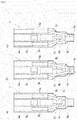
Fig.1 is a view that shows the structure of aninjector unit 1.Fig.1(a) is a front view of a partial section,Fig.1(b) is a side view of the partial section,Fig.1(c) is a back view,Fig.1(d) is a plan view, andFig.1(e) is a bottom view. As illustrated inFig.1 , theinjector unit 1 includes twoCNG injectors igniter 3, and acasing 4 to house therein the injectors and the igniter. - The
injector 2 is a solenoid injector that is broadly used as an injector for a port injection. By referring toFig. 1(a) , theinjector 2 includes arear part 2a configured to store a filter and etc. inside, acenter part 2b configured to store a solenoid for driving a needle valve, and etc. inside, and atip part 2c configured to arrange the needle valve, a nozzle, and etc. The diameter of thecenter part 2b is larger than that of thetip part 2c, and typically, more than twice. - The
igniter 3 is one kind of ignition means for igniting CNG. Theigniter 3 is one kind of spark plugs that generate high voltage by the boosting system through a resonator and perform the discharge. By the discharge, electrons are released from the gaseous molecules existed in the neighborhood, and unbalanced plasma, i.e., non local thermodynamic equilibrium plasma is generated. Thereby, the fuel is ignited. CNG has an ignition temperature higher than the temperature of the diesel oil, and the compression self ignition is difficult. Therefore, in theinjector unit 1 of the present invention, theigniter 3 is used for assisting the ignition. - By referring to
Fig. 1(a) andFig. 2(a) , theigniter 3 is divided into aninput part 3a configured to input a microwave, acoupling part 3b configured to perform the capacity coupling for the purpose of, for example, attaining an impedance matching between the microwave and theigniter 3, and an amplification/discharge part 3c configured to amplify the voltage and perform the discharge. By referring toFig. 1(b) , theigniter 3 is bent at a boundary of theinput part 3a and thecoupling part 3b and a boundary of thecoupling part 3b and the amplification/discharge part 3c. Each member of theigniter 3 is housed in acase 31 that is composed of metal having the conductivity. The structure of theigniter 3 is described in details below. - The
casing 4 is a cylindrical member that includes a plurality of cylindrical parts. As illustrated inFig. 1(a) , thecasing 4 is divided into arear part 4a, acenter part 4b, and atip part 4c. The diameters of respective parts are gradually smaller in 4a, 4b, and 4c order. Here, by referring toFig. 1(d) or Fig. 1(e) , twoinjectors 2 are positioned in point symmetry with regard to the center of thecasing 4. Theigniter 3 is positioned in a direction intersecting with a line that connects the injector 2A to the injector 2B. - The
injector unit 1 is, entirely, i.e., with the state of including the casing 4 (together with the casing 4), inserted into a cylinder head of the diesel engine that is one kind of compression self ignition system engines. Thecasing 4 is constituted of metal that has a high thermal conductivity, in relation to heat release ofCNG injector 2 andigniter 3. Accordingly, in fact, theinjector 2 and theigniter 3 are hidden inside thecasing 4, and therefore, they cannot be visually recognized when theinjector unit 1 is seen from, for example, the front. However, thecasing 4 is illustrated as transparent in the figure for convenience of explanation. - In an example of
Fig. 1 , therear part 2a and thecenter part 2b of theinjector 2 are arranged in therear part 4a of thecasing 4, and thetip part 2c is arranged in thecenter part 4b. Moreover, theinput part 3a of theigniter 3 is arranged in therear part 4a of thecasing 4. Thecoupling part 3b is arranged on the way of extension from therear part 4a to thecenter part 4b. The amplification/discharge part 3c is arranged in thecenter part 4b. - The
injector 2 has a larger diameter in thecenter part 2b, compared to thetip part 2c. Therefore, if theigniter 3 has a straight type as an usual igniter, theinput part 3a of theigniter 3 and thecenter part 2b of the injector are interfered with each other. On the other hand, in the present invention, since theigniter 3 is bent, theinput part 3a and thecenter part 2b are not interfered with each other. - In other words, if the
igniter 3 has a straight type, the amplification/discharge part 3c cannot be arranged in thecenter part 4b of the casing, and there is no choice but to arrange in therear part 4a. As a result, the discharge occurs at the rear side from an injection port of theinjector 2, and therefore, it is difficult to ignite the fuel. - If two
injectors 2 are aligned out of the center line (line passing through the center of casing 4), for example, if twoinjectors 2 are shifted to the left side of the sheet inFig. 1(b) , both of the tip part of theinjector 2 and the tip part of theigniter 3 can be arranged so as to be positioned inside thecenter part 4b of the casing, even if theigniter 3 may not be manufactured as the bending structure. However, considering into the injection performance, twoinjectors 2 are preferably positioned in point symmetry with regard to the center of thecasing 4. Accordingly, adoption of the bending structure of theigniter 3 contributes to the injection performance improvement of theinjector 2. - Next, the structure of the
igniter 3 is explained. The sectional front view of theigniter 3,Fig. 2(b) is referred to. Theinput part 3a includes aninput terminal 32 for inputting the microwave that is generated in an outside oscillation circuit, and afirst center electrode 33a. Thefirst center electrode 33a transmits the microwave. A dielectric 39a such as ceramic is provided between thefirst center electrode 33a and thecase 31. - The
coupling part 3b includes afirst center electrode 33b, and asecond center electrode 34. Thecoupling part 3b is provided for mainly aiming to attain an impedance matching between the oscillation circuit and theigniter 3. Thefirst electrode 33b is connected to thefirst electrode 33a, and it bends at a connection point. Thesecond electrode 34 has a cylindrical structure that includes a bottom part at the amplification/discharge part 3c side. The cylindrical part surrounds around thefirst center electrode 33b. The stick typefirst center electrode 33b opposes to the inner wall of the cylindricalsecond center electrode 34. In this opposing portion, the microwave from the first center electrode 33 is transmitted to thesecond center electrode 34 by capacity-coupling. In the cylindrical part of thesecond center electrode 34, a dielectric 39b such as ceramic is filled, and a dielectric 39a such as ceramic is provided between thesecond center electrode 34 and thecase 31. - The amplification/
discharge part 3c includes athird center electrode 35, and adischarge electrode 36. Thecenter electrode 35 is connected to thesecond center electrode 34, and the microwave of thesecond center electrode 34 is transmitted. Thedischarge electrode 36 is mounted to the tip end of thethird center electrode 35. Thethird center electrode 35 behaves as a coil element in this situation, and a potential of the microwave gradually becomes higher with passage of thethird center electrode 35. As a result, several tens of kilovolts of high voltage occurs between thedischarge electrode 36 and thecase 31, and the discharge is caused between thedischarge electrode 36 and thecase 31. -
Fig. 3 is a view that illustrates an equivalent circuit of theigniter 3. The microwave (voltage V1, frequency 2.45GHz) inputted from the outside oscillation circuit (MW) is connected to a resonation circuit that is constituted of a capacitor C3, a reactance L, and a capacitor C2 via a capacitor C1. Moreover, a discharger is provided in parallel with the capacitor C3. - Here, C1 corresponds to a coupling capacity, and C1 is determined mainly by a positional relationship between the
second center electrode 34 and the first center electrode 33 (distance between both electrodes and area determined by the mutually opposing portion) and a material filled between the electrodes, in the present embodiment, a dielectric 39b having the ceramic structure. The first center electrode 33 may be constituted to move in an axial direction in order to adjust the impedance easily. - The capacitor C2 is a ground capacitance formed by the
second center electrode 34 and thecase 31. C2 is determined by the distance between thesecond center electrode 34 and thecase 31, the area determined by mutually opposing portion, and a dielectric constant of the dielectric 39c. Thecase 31 is formed by the conductive metal, and functions also as the ground electrode. - Reactance L corresponds to a coil element of the
third center electrode 35. - The capacitor C3 is a discharge capacitance formed by the
third center electrode 35, thedischarge electrode 36, and thecase 31. C3 is determined by such as (1) shape and size of thedischarge electrode 36, and distance between thedischarge electrode 36 and thecase 31, (2) distance between thethird center electrode 35 and thecase 31, and (3) space (air layer) 37 provided between thethird center electrode 35 and thecase 31 and thickness of the dielectric 39d. If C2≫C3, the potential difference between the both ends of the capacitor C3 can sufficiently become larger than V1. As a result, thedischarge electrode 36 can become high in an electric potential. Further, since C3 can become smaller, the area of the capacitor can be made small. Of thethird center electrode 35 and thecase 31, the capacitor C3 is substantially determined by opposing portion under the-dielectric 39d-sandwitched-state. Conversely, the capacitor C3 can be adjusted by changing the length in the axial direction of the space (air layer) 37. - If the coupling capacitor C1 is considered to be small sufficiently, the capacitor C3, the reactance L, the capacitance C2, form a series resonance circuit, and the resonance frequency f can be expressed in a mathematical formula 1:

formula 1,
- In short, if f=2.45GHz, the
igniter 3 is designed such that the discharge capacitance C3, the coil reactance L, and the ground capacitance C2 satisfy the relationship of theformula 1. - As described above, the
igniter 3 generates the voltage Vc3 higher than the source voltage (voltage V1 of microwave inputted into the igniter 3), based on the boosting system by the resonator. Thereby, the discharge is caused between thedischarge electrode 36 and the ground electrode (case 31). When the discharge voltage exceeds the breakdown voltage of the gaseous molecules existed in the neighborhood, electrons are released from the gaseous molecules, non local thermodynamic equilibrium plasma is generated, and the fuel is ignited. - Moreover, since the frequency band of 2.45 GHz is used, the capacitance of the capacitor can be made small, and the
igniter 3 has advantage for downsizing. Further, as a result that the boosting system is adopted, only the vicinity of thedischarge electrode 36 of theigniter 3 becomes high in electric potential, and therefore the isolation characteristics is prominent and superior. From these points, the igniter in the present invention is superior to the conventional-resonance-structure-igniter (for example, Patent document 4). - Further, since the
igniter 3 adopts a bending structure, the igniter can be inserted into a narrow space such as aninjector unit 1 of the present invention. - Note that, the
igniter 3 is bent at the boundary of theinput part 3a and thecoupling part 3b, and the boundary of thecoupling part 3b and the amplification/discharge part 3c. If theigniter 3 is bent at thecoupling part 3b, a distribution of the size of the capacity coupling between the first center electrode 33 and thesecond center electrode 34 does not become in an axial symmetry. As a result, the discharge caused by thedischarge electrode 36 has a directivity, and therefore, it is undesirable. Moreover, supposing the cylindrical member, thesecond center electrode 34 is bent, manufacturing is difficult. - On the other hand, the first center electrode 33 and the
second center electrode 34 are not opposed with each other at the boundary of theinput part 3a and thecoupling part 3b. Therefore, the bending at this position does not influence so much the size of the capacity coupling between the first center electrode 33 and thesecond center electrode 34. Accordingly, since the design value of the igniter that is already designed can be utilized, the number of electric design steps can be reduced. - Note that, the bending portion of the
above igniter 3 has a horn shape; however, it may be R shape, i.e., being bent in gentle round shape. - An embodiment illustrated in
Fig. 4 can be considered. - As illustrated in
Fig. 4(a) , theigniter 3 having only one bending portion may be used. According to this configuration, the discharging position of the igniter can be closed to the jet stream of the injector. Note that, theigniter 3 has a bending portion at the boundary of theinput part 3a and thecoupling part 3b, and is not bent at the boundary of thecoupling part 3b and the amplification/discharge part 3c. - As illustrated in
Fig. 4(b) , theigniter 3 configured to increase the length of thecoupling part 3b may be used. According to this configuration, the tip part of the injector and the tip part of the igniter can be arranged in thetip part 4c of thecasing 4, and the injection port of the injector and the discharger of the igniter can be approached to the combustion chamber. Thereby, an ignition performance by theinjector unit 1 can be enhanced. Note that, theigniter 3 extends the length of the part of thefirst center electrode 33b that does not oppose to thesecond center electrode 34. - As illustrated in
Fig. 4(c) , theigniter 3 configured to increase the length of thecoupling part 3b and be bent at only one position, may be used. According to this configuration, the injection port of the injector can be approached to the combustion chamber, and the discharging position of the igniter can be closed to the jet stream of the injector. - Which one of the above (a) to (c) is adopted depends on the shape and the size of a hole (hole for injector insertion) of the cylinder head into which the
injector unit 1 is mounted. The igniter of the present invention can be bent, and the length can be changed. Therefore, it is easier for coping with various kinds of cylinder heads. Specifically, if theinjector unit 1 is used for "retrofit", it is required to be coped with various types of cylinder heads of diesel engines, and designing an individual igniter in accordance to each engine is complicated. However, according to the igniter of the present invention, it is bent at a position that does not affect to the electric characteristics, or length adjustment is performed, and therefore, various shapes of igniters can be designed without increasing significantly the number of electric design steps. As a result, a development cost can be reduced, eventually cost reduction of products can be achieved, and thereby, purchasers receive benefits therefrom. - An embodiment illustrated in
Fig. 5 can be considered.Fig.5(a) is a front view of a partial section,Fig.5(b) is a side view of the partial section,Fig.5(c) is a back view,Fig. 5(d) is a plan view, andFig. 5(e) is a bottom view. - In the first and second embodiments, the tip part (amplification/
discharge part 3c) of theigniter 3 is aligned out of the center axis of thecasing 4; however, in the present embodiment, the tip part of theigniter 3 exists on the center axis line of thecasing 4. - If the
igniter 3 is constituted to be straight as an usual igniter, theinput part 3a of theigniter 3 and thecenter part 2b of the injector are interfered with each other. Therefore, the tip part of theigniter 3 cannot be arranged on the center axis line of the casing. - On the other hand, since the
igniter 3 of the present embodiment is bent, theigniter 3 and theinjector 2 are not interfered with each other, and the tip part of theigniter 3 can be arranged on the center axis line of the casing. That is, since the discharge by theigniter 3 is performed in the center of the casing, the fuel ignition performance can be improved. - An embodiment illustrated in
Fig. 6 can be considered. In the present embodiment, twoigniters 3 are used. - As illustrated in
Fig.6(a) , the tip parts (amplification/discharge part 3c) of theigniters 3 are arranged in thecenter part 4b of thecasing 4. According to this example, the discharge can be caused by theigniters 3 in the vicinity of the injection port of theinjector 2. - As illustrated in
Fig. 6(b) , the tip parts of theigniters 3 are exposed from thetip part 4c of thecasing 4, and projected toward the inside of the combustion chamber. Thereby, the discharge by theigniters 3 can be caused, and therefore, the fuel ignition performance can be improved. - As illustrated in
Fig. 6(c) , one igniter of twoigniters 3 is exposed from thetip part 4c of thecasing 4, while the other igniter is not exposed at the tip part, and the tip part is arranged in the vicinity of the injection port of theinjector 2. For example, before the fuel injection, theigniter 3 that is arranged in the vicinity of the injection port of theinjector 2 is discharged. In this state, by injecting the fuel, a plasma seed is generated. Further, after fuel injection, theigniter 3 that is exposed at the tip end from thecasing 4 is discharged, and the plasma seed is expanded. Thereby, the fuel ignition performance can be improved. - Note that, these embodiments are possible in implementation because of the bending structure of the
igniter 3. Supposing the invented igniter is constituted to be straight as the usual igniter, the above-mentioned arrangements are impossible. That is, by using theigniter 3 having the bending structure, the fuel ignition performance can be improved. - The above is description of embodiments of the present invention. The scope of the present invention is determined based on inventions described in the claims, and not limited to the above embodiments.
-
- 1
- Injector Unit
- 2
- Injector
- 3
- Igniter
- 3a
- Input Part
- 3b
- Coupling Part
- 3c
- Amplification/Discharge Part
- 31
- Case (Ground Electrode)
- 32
- Microwave Input Terminal
- 33
- First Center Electrode
- 34
- Second Center Electrode
- 35
- Third Center Electrode
- 36
- Discharge Electrode
- 37
- Space
- 39
- Dielectric
- 4
- Casing
Claims (2)
- An injector unit (1) comprising:an injector (2);an igniter (3) having a resonance structure configured to boost an inputted microwave and a discharger configured to perform a discharge; anda casing (4) configured to house therein the injector (2) and the igniter (3):wherein the igniter (3) comprises a first part configured to transmit the inputted microwave, a second part configured to perform a capacity coupling to attain an impedance matching between the microwave and the igniter (3), and a third part configured to transmit the capacity-coupled microwave to the discharger, andwherein the igniter (3) is bent at a boundary of the first part and the second part, a boundary of the second part and the third part, or inside the first part.
- An igniter (3) comprising:a discharger;a first part configured to transmit an inputted microwave;a second part configured to perform a capacity coupling to attain an impedance matching between the inputted microwave and the igniter; anda third part configured to transmit the capacity-coupled microwave to the discharger; andwherein the igniter (3) is bent at a boundary of the first part and the second part, a boundary of the second part and the third part, or inside the first part.
Applications Claiming Priority (3)
| Application Number | Priority Date | Filing Date | Title |
|---|---|---|---|
| JP2014159101 | 2014-08-04 | ||
| JP2014160899 | 2014-08-06 | ||
| PCT/JP2015/072031 WO2016021574A2 (en) | 2014-08-04 | 2015-08-04 | Injector unit, and spark plug |
Publications (2)
| Publication Number | Publication Date |
|---|---|
| EP3179091A2 true EP3179091A2 (en) | 2017-06-14 |
| EP3179091A4 EP3179091A4 (en) | 2017-06-21 |
Family
ID=55264732
Family Applications (1)
| Application Number | Title | Priority Date | Filing Date |
|---|---|---|---|
| EP15829019.7A Withdrawn EP3179091A4 (en) | 2014-08-04 | 2015-08-04 | Injector unit, and spark plug |
Country Status (4)
| Country | Link |
|---|---|
| US (1) | US20170241390A1 (en) |
| EP (1) | EP3179091A4 (en) |
| JP (1) | JP6620748B2 (en) |
| WO (1) | WO2016021574A2 (en) |
Families Citing this family (2)
| Publication number | Priority date | Publication date | Assignee | Title |
|---|---|---|---|---|
| WO2015182774A1 (en) * | 2014-05-29 | 2015-12-03 | イマジニアリング株式会社 | Injector having in-built ignition system |
| EP3184796A4 (en) * | 2014-08-22 | 2018-01-24 | Imagineering, Inc. | Ignition device-integrated injector, internal combustion engine, gas burner, and ignition device |
Family Cites Families (15)
| Publication number | Priority date | Publication date | Assignee | Title |
|---|---|---|---|---|
| US4561406A (en) * | 1984-05-25 | 1985-12-31 | Combustion Electromagnetics, Inc. | Winged reentrant electromagnetic combustion chamber |
| JP2006120649A (en) * | 2000-10-03 | 2006-05-11 | Nippon Soken Inc | Spark plug and ignition device using the same |
| US6712035B2 (en) * | 2002-03-26 | 2004-03-30 | General Motors Corporation | Diesel injection igniter and method |
| US7416137B2 (en) * | 2003-01-22 | 2008-08-26 | Vast Power Systems, Inc. | Thermodynamic cycles using thermal diluent |
| JP2004257248A (en) * | 2003-02-24 | 2004-09-16 | Hitachi Ltd | Ignition device for internal combustion engine |
| JP2006140072A (en) * | 2004-11-15 | 2006-06-01 | Hitachi Ltd | Spark ignition device for internal combustion engine and internal combustion engine provided with the spark ignition device |
| JP4876217B2 (en) * | 2005-09-20 | 2012-02-15 | イマジニアリング株式会社 | Ignition system, internal combustion engine |
| JP5261631B2 (en) * | 2007-07-12 | 2013-08-14 | イマジニアリング株式会社 | Ignition or plasma generator |
| JP5152653B2 (en) * | 2008-05-20 | 2013-02-27 | 株式会社エーイーティー | Ignition system using spark discharge ignition method and microwave plasma ignition method in combination |
| JP5413186B2 (en) * | 2009-12-25 | 2014-02-12 | 株式会社デンソー | High frequency plasma ignition device |
| CN103098324B (en) * | 2010-09-07 | 2014-07-30 | 日本特殊陶业株式会社 | Ignition system and spark plug |
| WO2012061397A2 (en) * | 2010-11-01 | 2012-05-10 | Mahle Powertrain, Llc | Turbulent jet ignition pre-chamber combustion system for spark ignition engines |
| WO2013073487A1 (en) * | 2011-11-18 | 2013-05-23 | 日本特殊陶業株式会社 | High-frequency plasma spark plug |
| JP6446628B2 (en) * | 2013-01-22 | 2019-01-09 | イマジニアリング株式会社 | Plasma generator and internal combustion engine |
| EP3225832A4 (en) * | 2014-11-24 | 2017-12-13 | Imagineering, Inc. | Ignition unit, ignition system, and internal combustion engine |
-
2015
- 2015-08-04 US US15/501,549 patent/US20170241390A1/en not_active Abandoned
- 2015-08-04 JP JP2016540235A patent/JP6620748B2/en not_active Expired - Fee Related
- 2015-08-04 WO PCT/JP2015/072031 patent/WO2016021574A2/en not_active Ceased
- 2015-08-04 EP EP15829019.7A patent/EP3179091A4/en not_active Withdrawn
Also Published As
| Publication number | Publication date |
|---|---|
| JP6620748B2 (en) | 2019-12-18 |
| WO2016021574A2 (en) | 2016-02-11 |
| WO2016021574A3 (en) | 2016-03-31 |
| US20170241390A1 (en) | 2017-08-24 |
| EP3179091A4 (en) | 2017-06-21 |
| JPWO2016021574A1 (en) | 2017-06-15 |
Similar Documents
| Publication | Publication Date | Title |
|---|---|---|
| EP3184796A1 (en) | Ignition device-integrated injector, internal combustion engine, gas burner, and ignition device | |
| EP3150840A1 (en) | Injector having in-built ignition system | |
| EP3150841A1 (en) | Injector having in-built ignition system | |
| US20150287574A1 (en) | Dual signal coaxial cavity resonator plasma generation | |
| EP3179091A2 (en) | Injector unit, and spark plug | |
| JP6739348B2 (en) | Ignition unit, ignition system, and internal combustion engine | |
| EP3184805A1 (en) | Compression-ignition type internal combustion engine, and internal combustion engine | |
| EP3364509A1 (en) | Ignition device | |
| US20040112351A1 (en) | Ignition system for internal combustion engine and ignition method of fuel charged in a fuel chamber | |
| EP2342789B1 (en) | Internal combustion engine having a spark plug with an improved firing face | |
| JP6726825B2 (en) | Injector unit | |
| EP3242010A1 (en) | Ignition system, and internal combustion engine | |
| JP6635341B2 (en) | Repair method for compression ignition type internal combustion engine | |
| EP3255743A1 (en) | Spark plug | |
| JPWO2016093351A1 (en) | Ignition device | |
| SA515361268B1 (en) | Plasma header gasket and system | |
| WO2016027877A1 (en) | Spark plug, and compression-ignition internal combustion engine | |
| EP3229331A2 (en) | Ignition device, ignition system, and connector | |
| JP2013191559A (en) | Spark plug, ignition device and engine | |
| HK1234469A1 (en) | Dual signal coaxial cavity resonator plasma generation |
Legal Events
| Date | Code | Title | Description |
|---|---|---|---|
| PUAI | Public reference made under article 153(3) epc to a published international application that has entered the european phase |
Free format text: ORIGINAL CODE: 0009012 |
|
| 17P | Request for examination filed |
Effective date: 20170224 |
|
| AK | Designated contracting states |
Kind code of ref document: A2 Designated state(s): AL AT BE BG CH CY CZ DE DK EE ES FI FR GB GR HR HU IE IS IT LI LT LU LV MC MK MT NL NO PL PT RO RS SE SI SK SM TR |
|
| AX | Request for extension of the european patent |
Extension state: BA ME |
|
| A4 | Supplementary search report drawn up and despatched |
Effective date: 20170519 |
|
| RIC1 | Information provided on ipc code assigned before grant |
Ipc: F02M 57/06 20060101AFI20170515BHEP Ipc: F02P 1/08 20060101ALN20170515BHEP Ipc: F02P 23/04 20060101ALI20170515BHEP |
|
| DAV | Request for validation of the european patent (deleted) | ||
| DAX | Request for extension of the european patent (deleted) | ||
| 17Q | First examination report despatched |
Effective date: 20181012 |
|
| STAA | Information on the status of an ep patent application or granted ep patent |
Free format text: STATUS: THE APPLICATION IS DEEMED TO BE WITHDRAWN |
|
| 18D | Application deemed to be withdrawn |
Effective date: 20190223 |