EP3179072A1 - Nacelle - Google Patents
Nacelle Download PDFInfo
- Publication number
- EP3179072A1 EP3179072A1 EP16200707.4A EP16200707A EP3179072A1 EP 3179072 A1 EP3179072 A1 EP 3179072A1 EP 16200707 A EP16200707 A EP 16200707A EP 3179072 A1 EP3179072 A1 EP 3179072A1
- Authority
- EP
- European Patent Office
- Prior art keywords
- section
- transition region
- nacelle
- recessed section
- recessed
- Prior art date
- Legal status (The legal status is an assumption and is not a legal conclusion. Google has not performed a legal analysis and makes no representation as to the accuracy of the status listed.)
- Withdrawn
Links
Images



Classifications
-
- F—MECHANICAL ENGINEERING; LIGHTING; HEATING; WEAPONS; BLASTING
- F01—MACHINES OR ENGINES IN GENERAL; ENGINE PLANTS IN GENERAL; STEAM ENGINES
- F01D—NON-POSITIVE DISPLACEMENT MACHINES OR ENGINES, e.g. STEAM TURBINES
- F01D25/00—Component parts, details, or accessories, not provided for in, or of interest apart from, other groups
- F01D25/24—Casings; Casing parts, e.g. diaphragms, casing fastenings
-
- B—PERFORMING OPERATIONS; TRANSPORTING
- B64—AIRCRAFT; AVIATION; COSMONAUTICS
- B64D—EQUIPMENT FOR FITTING IN OR TO AIRCRAFT; FLIGHT SUITS; PARACHUTES; ARRANGEMENT OR MOUNTING OF POWER PLANTS OR PROPULSION TRANSMISSIONS IN AIRCRAFT
- B64D33/00—Arrangement in aircraft of power plant parts or auxiliaries not otherwise provided for
- B64D33/02—Arrangement in aircraft of power plant parts or auxiliaries not otherwise provided for of combustion air intakes
-
- F—MECHANICAL ENGINEERING; LIGHTING; HEATING; WEAPONS; BLASTING
- F01—MACHINES OR ENGINES IN GENERAL; ENGINE PLANTS IN GENERAL; STEAM ENGINES
- F01D—NON-POSITIVE DISPLACEMENT MACHINES OR ENGINES, e.g. STEAM TURBINES
- F01D25/00—Component parts, details, or accessories, not provided for in, or of interest apart from, other groups
- F01D25/04—Antivibration arrangements
-
- F—MECHANICAL ENGINEERING; LIGHTING; HEATING; WEAPONS; BLASTING
- F01—MACHINES OR ENGINES IN GENERAL; ENGINE PLANTS IN GENERAL; STEAM ENGINES
- F01D—NON-POSITIVE DISPLACEMENT MACHINES OR ENGINES, e.g. STEAM TURBINES
- F01D9/00—Stators
- F01D9/02—Nozzles; Nozzle boxes; Stator blades; Guide conduits, e.g. individual nozzles
-
- F—MECHANICAL ENGINEERING; LIGHTING; HEATING; WEAPONS; BLASTING
- F02—COMBUSTION ENGINES; HOT-GAS OR COMBUSTION-PRODUCT ENGINE PLANTS
- F02C—GAS-TURBINE PLANTS; AIR INTAKES FOR JET-PROPULSION PLANTS; CONTROLLING FUEL SUPPLY IN AIR-BREATHING JET-PROPULSION PLANTS
- F02C7/00—Features, components parts, details or accessories, not provided for in, or of interest apart form groups F02C1/00 - F02C6/00; Air intakes for jet-propulsion plants
- F02C7/04—Air intakes for gas-turbine plants or jet-propulsion plants
-
- F—MECHANICAL ENGINEERING; LIGHTING; HEATING; WEAPONS; BLASTING
- F04—POSITIVE - DISPLACEMENT MACHINES FOR LIQUIDS; PUMPS FOR LIQUIDS OR ELASTIC FLUIDS
- F04D—NON-POSITIVE-DISPLACEMENT PUMPS
- F04D29/00—Details, component parts, or accessories
- F04D29/40—Casings; Connections of working fluid
- F04D29/52—Casings; Connections of working fluid for axial pumps
- F04D29/522—Casings; Connections of working fluid for axial pumps especially adapted for elastic fluid pumps
- F04D29/526—Details of the casing section radially opposing blade tips
-
- F—MECHANICAL ENGINEERING; LIGHTING; HEATING; WEAPONS; BLASTING
- F04—POSITIVE - DISPLACEMENT MACHINES FOR LIQUIDS; PUMPS FOR LIQUIDS OR ELASTIC FLUIDS
- F04D—NON-POSITIVE-DISPLACEMENT PUMPS
- F04D29/00—Details, component parts, or accessories
- F04D29/66—Combating cavitation, whirls, noise, vibration or the like; Balancing
- F04D29/661—Combating cavitation, whirls, noise, vibration or the like; Balancing especially adapted for elastic fluid pumps
- F04D29/663—Sound attenuation
- F04D29/664—Sound attenuation by means of sound absorbing material
-
- B—PERFORMING OPERATIONS; TRANSPORTING
- B64—AIRCRAFT; AVIATION; COSMONAUTICS
- B64D—EQUIPMENT FOR FITTING IN OR TO AIRCRAFT; FLIGHT SUITS; PARACHUTES; ARRANGEMENT OR MOUNTING OF POWER PLANTS OR PROPULSION TRANSMISSIONS IN AIRCRAFT
- B64D33/00—Arrangement in aircraft of power plant parts or auxiliaries not otherwise provided for
- B64D33/02—Arrangement in aircraft of power plant parts or auxiliaries not otherwise provided for of combustion air intakes
- B64D2033/0226—Arrangement in aircraft of power plant parts or auxiliaries not otherwise provided for of combustion air intakes comprising boundary layer control means
-
- F—MECHANICAL ENGINEERING; LIGHTING; HEATING; WEAPONS; BLASTING
- F05—INDEXING SCHEMES RELATING TO ENGINES OR PUMPS IN VARIOUS SUBCLASSES OF CLASSES F01-F04
- F05D—INDEXING SCHEME FOR ASPECTS RELATING TO NON-POSITIVE-DISPLACEMENT MACHINES OR ENGINES, GAS-TURBINES OR JET-PROPULSION PLANTS
- F05D2220/00—Application
- F05D2220/30—Application in turbines
- F05D2220/32—Application in turbines in gas turbines
- F05D2220/323—Application in turbines in gas turbines for aircraft propulsion, e.g. jet engines
-
- F—MECHANICAL ENGINEERING; LIGHTING; HEATING; WEAPONS; BLASTING
- F05—INDEXING SCHEMES RELATING TO ENGINES OR PUMPS IN VARIOUS SUBCLASSES OF CLASSES F01-F04
- F05D—INDEXING SCHEME FOR ASPECTS RELATING TO NON-POSITIVE-DISPLACEMENT MACHINES OR ENGINES, GAS-TURBINES OR JET-PROPULSION PLANTS
- F05D2270/00—Control
- F05D2270/01—Purpose of the control system
- F05D2270/17—Purpose of the control system to control boundary layer
-
- Y—GENERAL TAGGING OF NEW TECHNOLOGICAL DEVELOPMENTS; GENERAL TAGGING OF CROSS-SECTIONAL TECHNOLOGIES SPANNING OVER SEVERAL SECTIONS OF THE IPC; TECHNICAL SUBJECTS COVERED BY FORMER USPC CROSS-REFERENCE ART COLLECTIONS [XRACs] AND DIGESTS
- Y02—TECHNOLOGIES OR APPLICATIONS FOR MITIGATION OR ADAPTATION AGAINST CLIMATE CHANGE
- Y02T—CLIMATE CHANGE MITIGATION TECHNOLOGIES RELATED TO TRANSPORTATION
- Y02T50/00—Aeronautics or air transport
- Y02T50/60—Efficient propulsion technologies, e.g. for aircraft
Definitions
- the disclosure relates to a nacelle for a turbofan gas turbine engine comprising a diffuser having a main section and a recessed section.
- a turbofan gas turbine engine comprises a fan housed within an aerodynamic nacelle which typically comprises an intake lip and diffuser.
- the geometry of the intake lip and diffuser is chosen to maximise aerodynamic performance of the gas turbine engine in use.
- the geometry of the intake lip is designed to prevent flow separation at the corner of flight envelope conditions, and the geometry of the diffuser is designed to guide the air flow towards the fan.
- the nacelle is designed to be as small as possible in order to minimise drag at cruise conditions.
- turbofan gas turbine engine is designed to fit under an airframe wing, this places constraints on the size of the nacelle and other factors such as the ground clearance, for example.
- a nacelle for a turbofan gas turbine engine comprising in flow series an intake lip, a diffuser and a fan casing, the diffuser having, in flow series, a main section and a recessed section adjacent to the fan casing, wherein a transition region is provided between the main section and the recessed section and wherein the nacelle is provided with an arrangement to supply pressure in a region of either or both of the transition region and recessed section.
- the recessed section may allow a larger diameter fan to be housed within the nacelle when compared with conventional nacelle designs of a comparable outer diameter.
- the recessed section may allow a larger diameter fan to be accommodated whilst maintaining more conventional intake lip and main diffuser section geometries.
- the pressure supplied in the region of either or both of the transition region and recessed section may be positive. Additionally or alternatively, the pressure supplied in the region of either or both of the transition region and recessed section may be negative.
- the supply of pressure in either or both of the aforementioned regions may have the effect of stabilising, re-energising or eliminating the separation bubble, or controlling its size. This may improve engine performance.
- the transition region may be configured to promote flow separation and the formation of a separation bubble in the recessed section.
- the intake lip may be designed to inhibit flow separation under normal operational conditions and the main diffuser section may be designed to guide the airflow towards the fan whilst preventing or inhibiting flow separation.
- the transition region may have either or both of a gradient and a profile. This may, in use, cause flow separation to occur. This may promote the formation of a separation bubble in the recessed section.
- the inner diameter of the diffuser section at the upstream end of the transition region may be smaller than the inner diameter of the diffuser section at the downstream end of the transition region.
- the transition region may comprise a step, a slope or a curve.
- the transition region may comprise any generalised curve or profile.
- the axial length of the transition region may be less than the radial depth of the transition region. This may form a steep gradient or profile ensuring that flow separation occurs at the transition region, resulting in the formation of a separation bubble within the recessed section in front of the fan.
- the surface of the recessed section may be offset radially outward with respect to the surface of the main section.
- the inner diameter of the surface of the main diffuser section may be smaller than inner diameter of the surface of the recessed section.
- the radial depth of the recessed section may be between 0.1%-5% of the inner diameter of the fan casing.
- the radial depth of the recessed section may be between 1mm and 100mm, or between 2mm and 50mm, or between 4mm and 30mm, for example.
- the axial length of the recessed section may be between 0mm and 500mm, between 0.1mm and 500mm, between 1 mm and 500mm, between 1mm and 350mm, or between 10mm and 200mm, for example.
- the axial length of the transition region may be between 0mm and 100mm, or between 2mm and 50mm, or between 4mm and 20mm, for example.
- the axial length of the transition region may be less than the recessed depth of the recessed section.
- the recessed section may be annular. Therefore, there may be a single recessed annular section that extends around the entire inner circumference of the nacelle.
- the recessed section may be of a uniform radial depth or it may vary axially, circumferentially or both axially and circumferentially.
- the recessed section may comprise a circumferentially extending arcuate section.
- There may be a single recessed section in the form of a single circumferentially extending arcuate section.
- the circumferentially extending arcuate section may be located at the bottom of the nacelle when in use (e.g. towards the bottom when mounted under an aircraft wing).
- the circumferentially extending arcuate section may be located close to the intake sideline.
- the circumferentially extending arcuate sections may be evenly distributed around the circumference of the nacelle.
- the depth of the arcuate sections may be uniform, or may vary axially or circumferentially.
- at least one circumferentially extending arcuate section may have a depth that reduces in depth circumferentially from a central position towards the edges such that it is blended into the inner wall of the nacelle.
- the nacelle may comprise an acoustic liner provided on either or both of the surface of the transition region and the recessed section.
- the nacelle may further comprise one or more acoustic liner sections which project from the surface of the transition region. There may be a plurality of acoustic liner sections of differing lengths.
- the nacelle may further comprise one or more openings in the region of either or both of the transition region and the recessed section. Such openings may be arranged such that pressure can be applied in either or both of the region of the transition region and the recessed section. For example, there may be openings in the walls of either or both of the recessed section and the transition region. This may allow a negative pressure to be applied in order to stabilise or eliminate a separation bubble. Further, this may allow a positive pressure to be applied to aerodynamically re-energise the separation bubble.
- turbofan gas turbine engine comprising a nacelle in accordance with any statement herein.
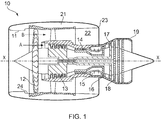
- Figure 1 shows a ducted fan gas turbine engine 10 having a principal and rotational axis X-X.
- the engine comprises, in axial flow series, an air intake 11, a propulsive fan 12, an intermediate pressure compressor 13, a high-pressure compressor 14, combustion equipment 15, a high-pressure turbine 16, an intermediate pressure turbine 17, a low-pressure turbine 18 and a core engine exhaust nozzle 19.
- a nacelle 21 generally surrounds the engine 10 and defines the intake 11, a bypass duct 22 and a bypass exhaust nozzle 23.
- air entering the intake 11 is accelerated by the fan 12 to produce two air flows: a first air flow A into the intermediate pressure compressor 13 and a second air flow B which passes through the bypass duct 22 to provide propulsive thrust.
- the intermediate pressure compressor 13 compresses the air flow A directed into it before delivering that air to the high pressure compressor 14 where further compression takes place.
- the compressed air exhausted from the high-pressure compressor 14 is directed into the combustion equipment 15 where it is mixed with fuel and the mixture combusted.
- the resultant hot combustion products then expand through, and thereby drive the high, intermediate and low-pressure turbines 16, 17, 18 before being exhausted through the nozzle 19 to provide additional propulsive thrust.
- the high, intermediate and low-pressure turbines respectively drive the high and intermediate pressure compressors 14, 13 and the fan 12 by suitable interconnecting shafts.
- FIG. 2 shows an enlarged view of the intake 11 of the nacelle 21 and the fan 12.
- the intake 11 comprises, in axial flow series, an intake lip 26, a diffuser 27 and a fan casing 32 which houses the fan 12.
- the diffuser 27 comprises, in axial flow series, a main section 28, a transition region 30 and a recessed section 24.
- the inner surface of the nacelle 21 is a revolved surface that is rotationally symmetric.
- the recessed section 24 is therefore annular and has a substantially constant radial depth.
- the recessed section 24 may not be annular and therefore the inner surface of the nacelle 21 may therefore not be rotationally symmetric.
- the radial depth of the recessed section 24 may vary in the circumferential direction.
- the transition region 30 is in the form of a step.
- the surface of the step forming the transition region 30 is perpendicular to the central axis X-X of the nacelle 21.
- the transition region step 30 forms a transition between the main diffuser section 28 and the recessed section 24 and has a radial depth R.
- the inner radius R U of the diffuser 27 at the upstream end of the transition region 30 is smaller than the inner radius of the diffuser 27 at the downstream R D end of the transition region 30.
- the difference between these two radii is the depth of the step R.
- the depth of the step R is the depth by which the surface of the recessed section 24 is outwardly radially offset from the surface of the main diffuser section 28.
- the nacelle 21 also comprises an acoustic liner 34, which in this arrangement is provided on the surface of the recessed section 24, transition region 30, and a portion of the length of the main diffuser section 28.
- the length of the diffuser 27, L D may be approximately 1 m, and the depth R of the recessed section 24 may be approximately 0.01 m. Since the transition region 30 is a step, the axial length of the transition region 30 is zero. The length L R of the recessed section 24 may be approximately 0.15 metres. It should be appreciated that the dimensions indicated above are merely examples and any suitable dimensions could be chosen depending on the size of either or both of the engine and the geometry of the nacelle 21, for example.
- the airflow follows the curvature of the intake lip 26 and the main diffuser section 28 as attached flow.
- the flow separates from the inner surface due to the profile of the step (which in this case is 90° with respect to the central axis). This results in the formation of a stable separation bubble 36 within the recessed section 24.
- the suction effect of the fan 12 suppresses the separation, which reduces the size of the separation bubble 36.
- the geometry and location of the transition region 30 and recessed section 24 results in negligible deterioration in the level of aerodynamic flow distortion reaching the fan 12.
- transition region 30 and a recessed section 24 allows the use of a larger diameter fan, whilst maintaining relatively conventional geometry for the intake lip 26 and the main diffuser section 28. This means that whilst flow separation does occur, it occurs at a known predictable location which can be accommodated for. Without the use of a transition region 30 and a recessed section 24, either the intake lip 26 would have to be made thinner or the main diffuser section 28 would have to be made steeper in order to accommodate the larger fan 12, or both. However, the redesign of the lip 26 and main diffuser 28 may result in more unpredictable flow separation, which may adversely affect the performance of the gas turbine engine. Further, the transition region 30 also provides additional surface area for the acoustic liner 34.
- transition region 30 and recessed section 24 allows the retention of a conventional or close to conventional intake lip 26 and main diffuser 28 geometry whilst accommodating a larger diameter fan 12.
- acoustic liner 34 may be provided which project from one or more of the surface of the main diffuser section 28, transition region 30 and recessed section 24.
- the liners may be substantially perpendicular from the surface, or may be inclined slightly. Further, there may be a plurality of projecting acoustic liner sections having different lengths. The lengths may be chosen to tune out specific fan tip frequencies. This may further enhance the suppression or damping of specific frequency acoustic waves.
- the nacelle 21 described in relation to figure 2 can be additionally provided with an arrangement to supply pressure.
- the arrangement can be configured to supply pressure in a region of either or both of the transition region 30 and the recessed section 24.
- the pressure supplied to either or both of the transition region 30 and the recessed section 24 can be positive. Additionally or alternatively, the pressure supplied to either or both of the transition region 30 and the recessed section 24 can be negative.
- the wall of the transition region 30 could be provided with one or more openings.
- the wall of the recessed section 24 could be provided with one or more openings. In this way, one or more such openings may be provided in the region of either or both of the transition region 30 and the recessed section 24. Such openings can allow air to be injected into or sucked away from either or both of the recessed section 24 and the transition region 30.
- the transition region 30 is in the form of a step perpendicular to the central axis.
- the transition region may be of any suitable shape.
- the transition region may comprise a slope having a constant gradient.
- the slope has a gradient ⁇ of 60° with respect to the central axis.
- the gradient could be 45°, 75° or 85°, for example.
- the gradient of the slope may be selected in order to promote flow separation, thereby forming a separation bubble 36 in the recessed section 24.
- the transition region 30 may comprise a curved surface of any suitable curvature.
- the curved surface could be inwardly or outwardly curved, the curvature being chosen to promote flow separation and the formation of a separation bubble 36.
- the length of the transition region, L T may be less than or equal to the radial depth R of the recessed section 24 so that flow separation occurs at the transition region 30. In other arrangements the length of the transition region, L T , may be greater than the radial depth R of the recessed section 24.
- the nacelle 21 described in relation to figures 3 or 4 can be additionally provided with an arrangement to supply pressure.
- the arrangement can be configured to supply pressure in a region of either or both of the transition region 30 and the recessed section 24.
- the pressure supplied to either or both of the transition region 30 and the recessed section 24 can be positive. Additionally or alternatively, the pressure supplied to either or both of the transition region 30 and the recessed section 24 can be negative.
- the wall of the transition region 30 could be provided with one or more openings.
- the wall of the recessed section 24 could be provided with one or more openings. In this way, one or more such openings may be provided in the region of either or both of the transition region 30 and the recessed section 24. Such openings can allow air to be injected into or sucked away from either or both of the recessed section 24 and the transition region 30.
- the nacelle 21 comprises a single annular recessed section 24. However, in other arrangements there may be one or more recessed sections, each in the form of a circumferentially extending arcuate section 38. As shown in Figure 5 , the nacelle 21 may comprise a single circumferentially extending arcuate section 38. In the arrangement shown in Figure 5 , the arcuate section 38 is positioned at the bottom of the nacelle 21 (i.e. it is located at the bottom of the nacelle 21 in use). Any suitable arc length for the recessed section may be chosen, for example 30°, 180°, or 270°. In the arrangement shown in Figure 5 , the circumferentially extending arcuate section 38 is "blended out". This means that the radial depth of the recessed section 24 varies in the circumferential direction, possibly non-uniformly, with the recessed section 24 being at its deepest towards, but not necessarily at, the centre, and reducing in depth towards either end.
- Figure 6 shows another arrangement in which there are a pair of recessed sections 24, each in the form of a circumferentially extending arcuate sections 38.
- the arc length of the sections 38 is approximately 30°, but it should be appreciated that any suitable arc length could be used.
- the pair of arcuate sections 38 are located diametrically opposite on the inner sides of the nacelle 21. As in the arrangement of Figure 5 , the edges of the arcuate sections 38 may be "blended out”.
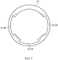
- Figure 7 shows a further arrangement in which there are three recessed sections 24, each comprising a circumferentially extending arcuate section 38 positioned in various locations around the inner circumference of the nacelle 21.
- this arrangement there is a first arcuate section 38 located at the bottom of the nacelle and a pair of diametrically opposite arcuate sections 38 located at the sides of the nacelle 21.
- the edges of the arcuate sections 38 may be "blended out”.
- recessed sections 24 in the form of arcuate sections 38 may allow the geometry of the nacelle to be designed to improve the performance of the gas turbine engine under certain conditions.
- the intake lip 26 may be made thicker towards the sides of the nacelle (i.e. only at the sides and not at the top and bottom).
- a pair of opposing recessed sections 24 in the form of arcuate sections 38 located at the sides could be used in order to accommodate the fan 12 without having to increase the outer diameter of the nacelle 21.
- the nacelle 21 described in relation to figures 5 , 6 or 7 can be additionally provided with one or more arrangements to supply pressure.
- the or each arrangement can be configured to supply pressure in a region of one or more transition regions 30 or one or more recessed sections 24, or both.
- the pressure supplied to either or both of the one or more transition regions 30 and the one or more recessed section 24 can be positive. Additionally or alternatively, the pressure supplied to either or both of the one or more transition regions 30 and the one or more recessed sections 24 can be negative.
- one or more walls of the transition regions 30 could be provided with a plurality of openings. Additionally or alternatively, one or more walls of the recessed sections 24 could be provided with a plurality of openings.
- one or more such openings may be provided in the region of either or both of the one or more transition regions 30 and the one or more recessed sections 24. Such openings can allow air to be injected into or sucked away from either or both of the one or more of recessed sections 24 and the one or more transition regions 30.
- the nacelle 21 may be provided with an arrangement for supplying pressure.
- pressure may be provided in the region of either or both of the transition region 30 and the recessed section 24.
- the pressure supplied in the region of either or both of the transition region 30 and recessed section 24 can be either or both of a positive and a negative pressure.
- the wall of either or both of the recessed section 24 and transition region 30 could be provided with a plurality of openings through which air could be sucked or injected. This may have the effect of stabilising the separation bubble 36 or controlling its size, or both. This may be desirable in order to improve engine performance.
- the arrangement can also include a controller.
- the controller can be configured to control the supply of pressure. Such pressure may be provided in the region of either or both of the transition region 30 and the recessed section 24.
- the controller can be configured to control the amount of either or both of the positive or the negative pressure supplied to the transition region 30 or the recessed section 24.
- the pressure applied can aid in one or more of the formation, stabilisation, aerodynamic re-energisation, elimination or control of the size of the separation bubble.
- the arrangement can also include a feedback device.
- the feedback device can be configured to monitor the supply of pressure.
- the feedback device can be configured to monitor and inform the controller of for example, environmental or engine conditions, or further parameters which can vary during use.
- the controller can be configured to vary either or both of the pressure supplied to the transition region 30 or the recessed section 24 in response to a feedback signal from the feedback device.
- the addition of a feedback device to the arrangement can aid in one or more of the formation, stabilisation, aerodynamic re-energisation, elimination or control of the size of the separation bubble during changeable operational, environmental or engine conditions.
- advantages in the form of increased fan diameter may also include a smaller nacelle external diameter or shorter intake for the same diameter fan, thereby reducing weight and drag and increasing overall efficiency.
Landscapes
- Engineering & Computer Science (AREA)
- Mechanical Engineering (AREA)
- General Engineering & Computer Science (AREA)
- Chemical & Material Sciences (AREA)
- Combustion & Propulsion (AREA)
- Aviation & Aerospace Engineering (AREA)
- Structures Of Non-Positive Displacement Pumps (AREA)
Abstract
Description
- The disclosure relates to a nacelle for a turbofan gas turbine engine comprising a diffuser having a main section and a recessed section.
- A turbofan gas turbine engine comprises a fan housed within an aerodynamic nacelle which typically comprises an intake lip and diffuser. The geometry of the intake lip and diffuser is chosen to maximise aerodynamic performance of the gas turbine engine in use. Specifically, the geometry of the intake lip is designed to prevent flow separation at the corner of flight envelope conditions, and the geometry of the diffuser is designed to guide the air flow towards the fan. The nacelle is designed to be as small as possible in order to minimise drag at cruise conditions.
- There is a trend in large civil aero engine gas turbine design to use larger diameter fans having a lower pressure ratio in order to enable overall cycle efficiency gains. However, in order to accommodate a larger diameter fan the dimensions of the nacelle must be increased proportionally to maintain equivalent intake aerodynamic performance. This results in a nacelle having an increased cross-section which may have a detrimental impact on both nacelle weight and drag.
- Further, since the turbofan gas turbine engine is designed to fit under an airframe wing, this places constraints on the size of the nacelle and other factors such as the ground clearance, for example.
- It is therefore desirable to provide an improved nacelle for a turbofan gas turbine engine which may allow a larger fan to be used when compared to existing nacelle designs.
- According to an aspect there is provided a nacelle for a turbofan gas turbine engine, comprising in flow series an intake lip, a diffuser and a fan casing, the diffuser having, in flow series, a main section and a recessed section adjacent to the fan casing, wherein a transition region is provided between the main section and the recessed section and wherein the nacelle is provided with an arrangement to supply pressure in a region of either or both of the transition region and recessed section. The recessed section may allow a larger diameter fan to be housed within the nacelle when compared with conventional nacelle designs of a comparable outer diameter. The recessed section may allow a larger diameter fan to be accommodated whilst maintaining more conventional intake lip and main diffuser section geometries.
- The pressure supplied in the region of either or both of the transition region and recessed section may be positive. Additionally or alternatively, the pressure supplied in the region of either or both of the transition region and recessed section may be negative. The supply of pressure in either or both of the aforementioned regions may have the effect of stabilising, re-energising or eliminating the separation bubble, or controlling its size. This may improve engine performance.
- The transition region may be configured to promote flow separation and the formation of a separation bubble in the recessed section. The intake lip may be designed to inhibit flow separation under normal operational conditions and the main diffuser section may be designed to guide the airflow towards the fan whilst preventing or inhibiting flow separation. The transition region may have either or both of a gradient and a profile. This may, in use, cause flow separation to occur. This may promote the formation of a separation bubble in the recessed section. The inner diameter of the diffuser section at the upstream end of the transition region may be smaller than the inner diameter of the diffuser section at the downstream end of the transition region.
- The transition region may comprise a step, a slope or a curve. The transition region may comprise any generalised curve or profile. In some arrangements, the axial length of the transition region may be less than the radial depth of the transition region. This may form a steep gradient or profile ensuring that flow separation occurs at the transition region, resulting in the formation of a separation bubble within the recessed section in front of the fan.
- The surface of the recessed section may be offset radially outward with respect to the surface of the main section. Thus, the inner diameter of the surface of the main diffuser section may be smaller than inner diameter of the surface of the recessed section.
- The radial depth of the recessed section may be between 0.1%-5% of the inner diameter of the fan casing. The radial depth of the recessed section may be between 1mm and 100mm, or between 2mm and 50mm, or between 4mm and 30mm, for example. The axial length of the recessed section may be between 0mm and 500mm, between 0.1mm and 500mm, between 1 mm and 500mm, between 1mm and 350mm, or between 10mm and 200mm, for example. The axial length of the transition region may be between 0mm and 100mm, or between 2mm and 50mm, or between 4mm and 20mm, for example.
- In some arrangements, the axial length of the transition region may be less than the recessed depth of the recessed section.
- The recessed section may be annular. Therefore, there may be a single recessed annular section that extends around the entire inner circumference of the nacelle. The recessed section may be of a uniform radial depth or it may vary axially, circumferentially or both axially and circumferentially. The recessed section may comprise a circumferentially extending arcuate section. There may be a single recessed section in the form of a single circumferentially extending arcuate section. The circumferentially extending arcuate section may be located at the bottom of the nacelle when in use (e.g. towards the bottom when mounted under an aircraft wing). The circumferentially extending arcuate section may be located close to the intake sideline.
- There may be a plurality of recessed sections, each comprising a circumferentially extending arcuate section. The circumferentially extending arcuate sections may be evenly distributed around the circumference of the nacelle. There may be a circumferentially extending arcuate section located at the bottom of the nacelle. There may be a pair of circumferentially extending arcuate sections located on diametrically opposite sides of the nacelle. The depth of the arcuate sections may be uniform, or may vary axially or circumferentially. For example, at least one circumferentially extending arcuate section may have a depth that reduces in depth circumferentially from a central position towards the edges such that it is blended into the inner wall of the nacelle.
- The nacelle may comprise an acoustic liner provided on either or both of the surface of the transition region and the recessed section. The nacelle may further comprise one or more acoustic liner sections which project from the surface of the transition region. There may be a plurality of acoustic liner sections of differing lengths.
- The nacelle may further comprise one or more openings in the region of either or both of the transition region and the recessed section. Such openings may be arranged such that pressure can be applied in either or both of the region of the transition region and the recessed section. For example, there may be openings in the walls of either or both of the recessed section and the transition region. This may allow a negative pressure to be applied in order to stabilise or eliminate a separation bubble. Further, this may allow a positive pressure to be applied to aerodynamically re-energise the separation bubble.
- According to another aspect, there is provided a turbofan gas turbine engine comprising a nacelle in accordance with any statement herein.
- Various arrangements will now be described, by way of example, with reference to the accompanying drawings, in which:
-
Figure 1 schematically a shows a cross-section of a turbofan gas turbine engine; -
Figure 2 schematically shows an enlarged view of the intake of the gas turbine engine ofFigure 1 according to a first arrangement; -
Figure 3 schematically shows an enlarged view of the intake of the gas turbine engine ofFigure 1 according to a second arrangement; -
Figure 4 schematically shows an enlarged view of the intake of the gas turbine engine ofFigure 1 according to a third arrangement; -
Figure 5 schematically shows a cross-section of the nacelle of the gas turbine engine ofFigure 1 according to a fourth arrangement; -
Figure 6 schematically shows a cross-section of the nacelle of the gas turbine engine ofFigure 1 according to a fifth arrangement; -
Figure 7 schematically shows a cross-section of the nacelle of the gas turbine engine ofFigure 1 according to a sixth arrangement; and -
Figure 8 schematically shows an enlarged view of the intake of the gas turbine engine ofFigure 1 according to a seventh arrangement. -
Figure 1 shows a ducted fangas turbine engine 10 having a principal and rotational axis X-X. The engine comprises, in axial flow series, anair intake 11, apropulsive fan 12, anintermediate pressure compressor 13, a high-pressure compressor 14,combustion equipment 15, a high-pressure turbine 16, anintermediate pressure turbine 17, a low-pressure turbine 18 and a coreengine exhaust nozzle 19. Anacelle 21 generally surrounds theengine 10 and defines theintake 11, abypass duct 22 and abypass exhaust nozzle 23. - During operation, air entering the
intake 11 is accelerated by thefan 12 to produce two air flows: a first air flow A into theintermediate pressure compressor 13 and a second air flow B which passes through thebypass duct 22 to provide propulsive thrust. Theintermediate pressure compressor 13 compresses the air flow A directed into it before delivering that air to thehigh pressure compressor 14 where further compression takes place. - The compressed air exhausted from the high-
pressure compressor 14 is directed into thecombustion equipment 15 where it is mixed with fuel and the mixture combusted. The resultant hot combustion products then expand through, and thereby drive the high, intermediate and low-pressure turbines nozzle 19 to provide additional propulsive thrust. The high, intermediate and low-pressure turbines respectively drive the high andintermediate pressure compressors fan 12 by suitable interconnecting shafts. -
Figure 2 shows an enlarged view of theintake 11 of thenacelle 21 and thefan 12. As shown, theintake 11 comprises, in axial flow series, anintake lip 26, adiffuser 27 and afan casing 32 which houses thefan 12. Thediffuser 27 comprises, in axial flow series, amain section 28, atransition region 30 and a recessedsection 24. In this arrangement the inner surface of thenacelle 21 is a revolved surface that is rotationally symmetric. The recessedsection 24 is therefore annular and has a substantially constant radial depth. However, it should be appreciated that in other embodiments the recessedsection 24 may not be annular and therefore the inner surface of thenacelle 21 may therefore not be rotationally symmetric. In some arrangements the radial depth of the recessedsection 24 may vary in the circumferential direction. - In this arrangement, the
transition region 30 is in the form of a step. The surface of the step forming thetransition region 30 is perpendicular to the central axis X-X of thenacelle 21. Thetransition region step 30 forms a transition between themain diffuser section 28 and the recessedsection 24 and has a radial depth R. Thus, the inner radius RU of thediffuser 27 at the upstream end of thetransition region 30 is smaller than the inner radius of thediffuser 27 at the downstream RD end of thetransition region 30. The difference between these two radii is the depth of the step R. The depth of the step R is the depth by which the surface of the recessedsection 24 is outwardly radially offset from the surface of themain diffuser section 28. Thenacelle 21 also comprises anacoustic liner 34, which in this arrangement is provided on the surface of the recessedsection 24,transition region 30, and a portion of the length of themain diffuser section 28. - For a fan diameter of approximately 2.5 m, the length of the
diffuser 27, LD, may be approximately 1 m, and the depth R of the recessedsection 24 may be approximately 0.01 m. Since thetransition region 30 is a step, the axial length of thetransition region 30 is zero. The length LR of the recessedsection 24 may be approximately 0.15 metres. It should be appreciated that the dimensions indicated above are merely examples and any suitable dimensions could be chosen depending on the size of either or both of the engine and the geometry of thenacelle 21, for example. - During operation of the turbofan gas turbine engine, the airflow follows the curvature of the
intake lip 26 and themain diffuser section 28 as attached flow. At thetransition region 30, the flow separates from the inner surface due to the profile of the step (which in this case is 90° with respect to the central axis). This results in the formation of astable separation bubble 36 within the recessedsection 24. The suction effect of thefan 12 suppresses the separation, which reduces the size of theseparation bubble 36. The geometry and location of thetransition region 30 and recessedsection 24 results in negligible deterioration in the level of aerodynamic flow distortion reaching thefan 12. - The use of a
transition region 30 and a recessedsection 24 allows the use of a larger diameter fan, whilst maintaining relatively conventional geometry for theintake lip 26 and themain diffuser section 28. This means that whilst flow separation does occur, it occurs at a known predictable location which can be accommodated for. Without the use of atransition region 30 and a recessedsection 24, either theintake lip 26 would have to be made thinner or themain diffuser section 28 would have to be made steeper in order to accommodate thelarger fan 12, or both. However, the redesign of thelip 26 andmain diffuser 28 may result in more unpredictable flow separation, which may adversely affect the performance of the gas turbine engine. Further, thetransition region 30 also provides additional surface area for theacoustic liner 34. This allows additionalacoustic liner 34 material to be provided which enhances the general acoustic damping of thefan 12. In summary, in this arrangement thetransition region 30 and recessedsection 24 allows the retention of a conventional or close toconventional intake lip 26 andmain diffuser 28 geometry whilst accommodating alarger diameter fan 12. - In addition or instead of providing an
acoustic liner 34 on the surface of themain diffuser section 28,transition region 30 and recessedsection 24, further acoustic liner sections may be provided which project from one or more of the surface of themain diffuser section 28,transition region 30 and recessedsection 24. The liners may be substantially perpendicular from the surface, or may be inclined slightly. Further, there may be a plurality of projecting acoustic liner sections having different lengths. The lengths may be chosen to tune out specific fan tip frequencies. This may further enhance the suppression or damping of specific frequency acoustic waves. - The
nacelle 21 described in relation tofigure 2 can be additionally provided with an arrangement to supply pressure. The arrangement can be configured to supply pressure in a region of either or both of thetransition region 30 and the recessedsection 24. The pressure supplied to either or both of thetransition region 30 and the recessedsection 24 can be positive. Additionally or alternatively, the pressure supplied to either or both of thetransition region 30 and the recessedsection 24 can be negative. In particular, the wall of thetransition region 30 could be provided with one or more openings. Additionally or alternatively, the wall of the recessedsection 24 could be provided with one or more openings. In this way, one or more such openings may be provided in the region of either or both of thetransition region 30 and the recessedsection 24. Such openings can allow air to be injected into or sucked away from either or both of the recessedsection 24 and thetransition region 30. - In the arrangement described above the
transition region 30 is in the form of a step perpendicular to the central axis. However, it should be appreciated that the transition region may be of any suitable shape. For example, as shown inFigure 3 the transition region may comprise a slope having a constant gradient. In the arrangement shown inFigure 3 the slope has a gradient θ of 60° with respect to the central axis. In other arrangements the gradient could be 45°, 75° or 85°, for example. The gradient of the slope may be selected in order to promote flow separation, thereby forming aseparation bubble 36 in the recessedsection 24. As shown inFigure 4 , thetransition region 30 may comprise a curved surface of any suitable curvature. For example, the curved surface could be inwardly or outwardly curved, the curvature being chosen to promote flow separation and the formation of aseparation bubble 36. In some arrangements, the length of the transition region, LT, may be less than or equal to the radial depth R of the recessedsection 24 so that flow separation occurs at thetransition region 30. In other arrangements the length of the transition region, LT, may be greater than the radial depth R of the recessedsection 24. - The
nacelle 21 described in relation tofigures 3 or4 can be additionally provided with an arrangement to supply pressure. The arrangement can be configured to supply pressure in a region of either or both of thetransition region 30 and the recessedsection 24. The pressure supplied to either or both of thetransition region 30 and the recessedsection 24 can be positive. Additionally or alternatively, the pressure supplied to either or both of thetransition region 30 and the recessedsection 24 can be negative. In particular, the wall of thetransition region 30 could be provided with one or more openings. Additionally or alternatively, the wall of the recessedsection 24 could be provided with one or more openings. In this way, one or more such openings may be provided in the region of either or both of thetransition region 30 and the recessedsection 24. Such openings can allow air to be injected into or sucked away from either or both of the recessedsection 24 and thetransition region 30. - In the arrangements described above the
nacelle 21 comprises a single annular recessedsection 24. However, in other arrangements there may be one or more recessed sections, each in the form of a circumferentially extending arcuate section 38. As shown inFigure 5 , thenacelle 21 may comprise a single circumferentially extending arcuate section 38. In the arrangement shown inFigure 5 , the arcuate section 38 is positioned at the bottom of the nacelle 21 (i.e. it is located at the bottom of thenacelle 21 in use). Any suitable arc length for the recessed section may be chosen, for example 30°, 180°, or 270°. In the arrangement shown inFigure 5 , the circumferentially extending arcuate section 38 is "blended out". This means that the radial depth of the recessedsection 24 varies in the circumferential direction, possibly non-uniformly, with the recessedsection 24 being at its deepest towards, but not necessarily at, the centre, and reducing in depth towards either end. -
Figure 6 shows another arrangement in which there are a pair of recessedsections 24, each in the form of a circumferentially extending arcuate sections 38. In this arrangement the arc length of the sections 38 is approximately 30°, but it should be appreciated that any suitable arc length could be used. The pair of arcuate sections 38 are located diametrically opposite on the inner sides of thenacelle 21. As in the arrangement ofFigure 5 , the edges of the arcuate sections 38 may be "blended out". -
Figure 7 shows a further arrangement in which there are three recessedsections 24, each comprising a circumferentially extending arcuate section 38 positioned in various locations around the inner circumference of thenacelle 21. In this arrangement there is a first arcuate section 38 located at the bottom of the nacelle and a pair of diametrically opposite arcuate sections 38 located at the sides of thenacelle 21. As for the arrangements ofFigures 5 and6 , the edges of the arcuate sections 38 may be "blended out". - The use of one or more recessed
sections 24 in the form of arcuate sections 38 may allow the geometry of the nacelle to be designed to improve the performance of the gas turbine engine under certain conditions. For example, to reduce the effects of crosswind on engine performance, theintake lip 26 may be made thicker towards the sides of the nacelle (i.e. only at the sides and not at the top and bottom). In order to avoid the diffuser having to have an abnormally steep gradient, a pair of opposing recessedsections 24 in the form of arcuate sections 38 located at the sides could be used in order to accommodate thefan 12 without having to increase the outer diameter of thenacelle 21. - The
nacelle 21 described in relation tofigures 5 ,6 or7 can be additionally provided with one or more arrangements to supply pressure. The or each arrangement can be configured to supply pressure in a region of one ormore transition regions 30 or one or more recessedsections 24, or both. The pressure supplied to either or both of the one ormore transition regions 30 and the one or more recessedsection 24 can be positive. Additionally or alternatively, the pressure supplied to either or both of the one ormore transition regions 30 and the one or more recessedsections 24 can be negative. In particular, one or more walls of thetransition regions 30 could be provided with a plurality of openings. Additionally or alternatively, one or more walls of the recessedsections 24 could be provided with a plurality of openings. In this way, one or more such openings may be provided in the region of either or both of the one ormore transition regions 30 and the one or more recessedsections 24. Such openings can allow air to be injected into or sucked away from either or both of the one or more of recessedsections 24 and the one ormore transition regions 30. - As shown in
Figure 8 , thenacelle 21 may be provided with an arrangement for supplying pressure. Such pressure may be provided in the region of either or both of thetransition region 30 and the recessedsection 24. The pressure supplied in the region of either or both of thetransition region 30 and recessedsection 24 can be either or both of a positive and a negative pressure. In particular, the wall of either or both of the recessedsection 24 andtransition region 30 could be provided with a plurality of openings through which air could be sucked or injected. This may have the effect of stabilising theseparation bubble 36 or controlling its size, or both. This may be desirable in order to improve engine performance. - The arrangement can also include a controller. The controller can be configured to control the supply of pressure. Such pressure may be provided in the region of either or both of the
transition region 30 and the recessedsection 24. In particular, the controller can be configured to control the amount of either or both of the positive or the negative pressure supplied to thetransition region 30 or the recessedsection 24. Advantageously, the pressure applied can aid in one or more of the formation, stabilisation, aerodynamic re-energisation, elimination or control of the size of the separation bubble. - The arrangement can also include a feedback device. The feedback device can be configured to monitor the supply of pressure. In particular, the feedback device can be configured to monitor and inform the controller of for example, environmental or engine conditions, or further parameters which can vary during use. In this way, the controller can be configured to vary either or both of the pressure supplied to the
transition region 30 or the recessedsection 24 in response to a feedback signal from the feedback device. Advantageously, the addition of a feedback device to the arrangement can aid in one or more of the formation, stabilisation, aerodynamic re-energisation, elimination or control of the size of the separation bubble during changeable operational, environmental or engine conditions. - It should be noted that, while the above description has described advantages in the form of increased fan diameter, the advantages may also include a smaller nacelle external diameter or shorter intake for the same diameter fan, thereby reducing weight and drag and increasing overall efficiency.
Claims (14)
Applications Claiming Priority (1)
| Application Number | Priority Date | Filing Date | Title |
|---|---|---|---|
| GBGB1521871.2A GB201521871D0 (en) | 2015-12-11 | 2015-12-11 | Nacelle |
Publications (1)
| Publication Number | Publication Date |
|---|---|
| EP3179072A1 true EP3179072A1 (en) | 2017-06-14 |
Family
ID=55274579
Family Applications (1)
| Application Number | Title | Priority Date | Filing Date |
|---|---|---|---|
| EP16200707.4A Withdrawn EP3179072A1 (en) | 2015-12-11 | 2016-11-25 | Nacelle |
Country Status (3)
| Country | Link |
|---|---|
| US (1) | US10392971B2 (en) |
| EP (1) | EP3179072A1 (en) |
| GB (1) | GB201521871D0 (en) |
Citations (4)
| Publication number | Priority date | Publication date | Assignee | Title |
|---|---|---|---|---|
| US20080092548A1 (en) * | 2006-10-20 | 2008-04-24 | United Technologies Corporation | Gas turbine engine having slim-line nacelle |
| EP2060489A2 (en) * | 2007-11-13 | 2009-05-20 | United Technologies Corporation | Nacelle flow assembly |
| US20120031501A1 (en) * | 2010-08-09 | 2012-02-09 | Yen Tuan | Aviation engine inlet with tangential blowing for buzz saw noise control |
| EP2607657A2 (en) * | 2011-12-20 | 2013-06-26 | Rolls-Royce plc | Active flow control intake for a gas turbine engine |
Family Cites Families (7)
| Publication number | Priority date | Publication date | Assignee | Title |
|---|---|---|---|---|
| GB1291943A (en) | 1970-02-11 | 1972-10-04 | Secr Defence | Improvements in or relating to ducted fans |
| GB9602130D0 (en) | 1996-02-02 | 1996-04-03 | Rolls Royce Plc | Improved method of combining ducted fan gas turbine engine modules and aircraft structure |
| GB2385382B (en) | 2002-02-13 | 2006-02-15 | Rolls Royce Plc | A cowl structure for a gas turbine engine |
| US8261530B2 (en) * | 2009-05-01 | 2012-09-11 | United Technologies Corporation | Cambered aero-engine inlet |
| US20130283821A1 (en) * | 2012-04-30 | 2013-10-31 | Jonathan Gilson | Gas turbine engine and nacelle noise attenuation structure |
| US9777582B2 (en) | 2012-07-03 | 2017-10-03 | United Technologies Corporation | Tip leakage flow directionality control |
| US20160084108A1 (en) | 2014-09-24 | 2016-03-24 | Honeywell International Inc. | Nacelle inlet and engine fan housing assembly and method for making same |
-
2015
- 2015-12-11 GB GBGB1521871.2A patent/GB201521871D0/en not_active Ceased
-
2016
- 2016-11-25 EP EP16200707.4A patent/EP3179072A1/en not_active Withdrawn
- 2016-11-25 US US15/361,234 patent/US10392971B2/en active Active
Patent Citations (4)
| Publication number | Priority date | Publication date | Assignee | Title |
|---|---|---|---|---|
| US20080092548A1 (en) * | 2006-10-20 | 2008-04-24 | United Technologies Corporation | Gas turbine engine having slim-line nacelle |
| EP2060489A2 (en) * | 2007-11-13 | 2009-05-20 | United Technologies Corporation | Nacelle flow assembly |
| US20120031501A1 (en) * | 2010-08-09 | 2012-02-09 | Yen Tuan | Aviation engine inlet with tangential blowing for buzz saw noise control |
| EP2607657A2 (en) * | 2011-12-20 | 2013-06-26 | Rolls-Royce plc | Active flow control intake for a gas turbine engine |
Also Published As
| Publication number | Publication date |
|---|---|
| US20170167295A1 (en) | 2017-06-15 |
| GB201521871D0 (en) | 2016-01-27 |
| US10392971B2 (en) | 2019-08-27 |
Similar Documents
| Publication | Publication Date | Title |
|---|---|---|
| US9004399B2 (en) | Nacelle flow assembly | |
| US10513984B2 (en) | System for suppressing acoustic noise within a gas turbine combustor | |
| US10907503B2 (en) | Compressors with integrated secondary air flow systems | |
| US20140363276A1 (en) | Ultra high bypass ratio turbofan engine | |
| US9488191B2 (en) | Gas turbine diffuser strut including coanda flow injection | |
| US10920713B2 (en) | Compression cowl for jet engine exhaust | |
| US9869276B2 (en) | Engine duct and aircraft engine | |
| US10371173B2 (en) | Liner for a gas turbine engine | |
| US10550704B2 (en) | High performance convergent divergent nozzle | |
| US10513980B2 (en) | Gas turbine engine arrangement | |
| US20140215998A1 (en) | Gas turbine engines with improved compressor blades | |
| EP3159524B1 (en) | Compact nacelle with contoured fan nozzle | |
| CN103032173B (en) | Conformal inlet device for gas-turbine unit | |
| EP3536902B1 (en) | Gas turbine engine component | |
| CA2666190C (en) | Nacelle drag reduction device for a turbofan gas turbine engine | |
| US9885285B2 (en) | Gas turbine engine nacelle | |
| US10392971B2 (en) | Nacelle | |
| US20210355873A1 (en) | Nacelle for gas turbine engine | |
| US20130091849A1 (en) | Augmentor spray bar with tip support bushing | |
| EP3118416B1 (en) | A gas turbine engine |
Legal Events
| Date | Code | Title | Description |
|---|---|---|---|
| PUAI | Public reference made under article 153(3) epc to a published international application that has entered the european phase |
Free format text: ORIGINAL CODE: 0009012 |
|
| STAA | Information on the status of an ep patent application or granted ep patent |
Free format text: STATUS: THE APPLICATION HAS BEEN PUBLISHED |
|
| AK | Designated contracting states |
Kind code of ref document: A1 Designated state(s): AL AT BE BG CH CY CZ DE DK EE ES FI FR GB GR HR HU IE IS IT LI LT LU LV MC MK MT NL NO PL PT RO RS SE SI SK SM TR |
|
| AX | Request for extension of the european patent |
Extension state: BA ME |
|
| STAA | Information on the status of an ep patent application or granted ep patent |
Free format text: STATUS: REQUEST FOR EXAMINATION WAS MADE |
|
| 17P | Request for examination filed |
Effective date: 20171114 |
|
| RBV | Designated contracting states (corrected) |
Designated state(s): AL AT BE BG CH CY CZ DE DK EE ES FI FR GB GR HR HU IE IS IT LI LT LU LV MC MK MT NL NO PL PT RO RS SE SI SK SM TR |
|
| STAA | Information on the status of an ep patent application or granted ep patent |
Free format text: STATUS: EXAMINATION IS IN PROGRESS |
|
| RIN1 | Information on inventor provided before grant (corrected) |
Inventor name: CHRISTOPHER, SHEAF Inventor name: CHRISTIE, ROBERT Inventor name: SMITH, ANGUS Inventor name: MACMANUS, DAVID |
|
| 17Q | First examination report despatched |
Effective date: 20190410 |
|
| RAP1 | Party data changed (applicant data changed or rights of an application transferred) |
Owner name: ROLLS-ROYCE PLC |
|
| STAA | Information on the status of an ep patent application or granted ep patent |
Free format text: STATUS: THE APPLICATION HAS BEEN WITHDRAWN |
|
| 18W | Application withdrawn |
Effective date: 20231025 |